verilog hdl - sharif
TRANSCRIPT

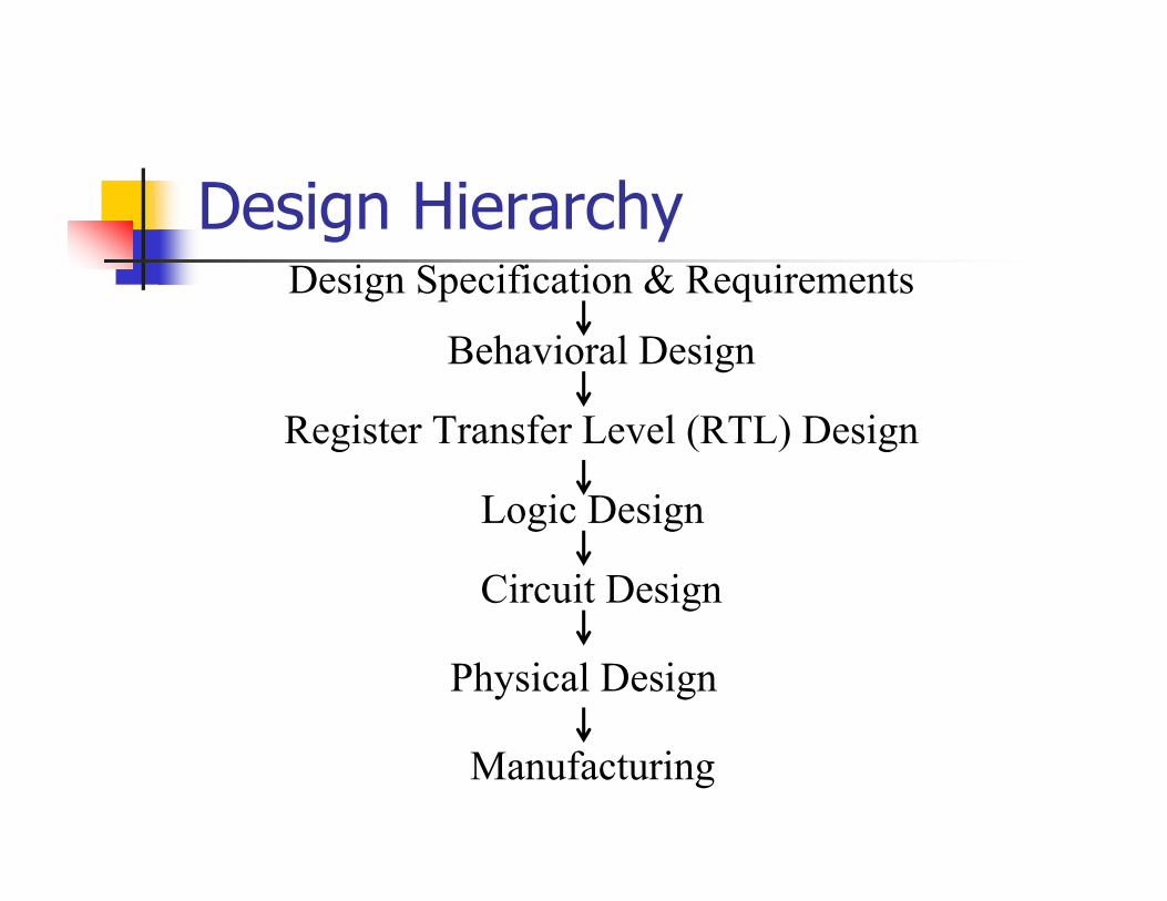
Design HierarchyDesign Specification & Requirements
Behavioral Design
Register Transfer Level (RTL) Design
Logic Design
Circuit Design
Physical Design
Manufacturing

Design Automation (DA)
Automatic doing task in design process:Transforming one form of design to anotherVerifying functionality and timing of designGenerating test sequence for design validationDocumentation…
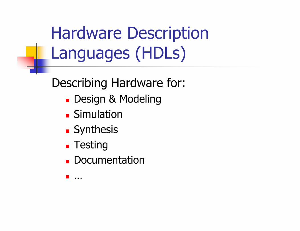
Hardware Description Languages (HDLs)
Describing Hardware for:Design & ModelingSimulationSynthesisTestingDocumentation…

Top-Down Design
System
S1 S2 S3
S11 S12 S13 S31 S32
S311 S312S121 S122 S123
Verilog General Features
Support for timing information
Support for concurrency
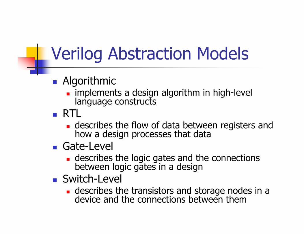
Verilog Abstraction ModelsAlgorithmic
implements a design algorithm in high-level language constructs
RTLdescribes the flow of data between registers and how a design processes that data
Gate-Leveldescribes the logic gates and the connections between logic gates in a design
Switch-Leveldescribes the transistors and storage nodes in a device and the connections between them
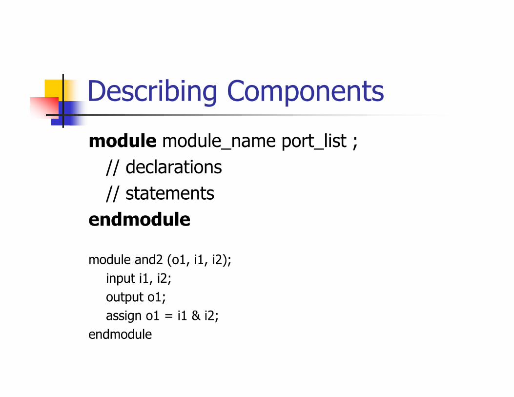
Describing Components
module module_name port_list ;// declarations// statements
endmodule
module and2 (o1, i1, i2);input i1, i2;output o1;assign o1 = i1 & i2;
endmodule

Verilog Logic System
4 value logic system0 zero, false1 one, trueX unknown, conflictZ high-impedance, unconnected
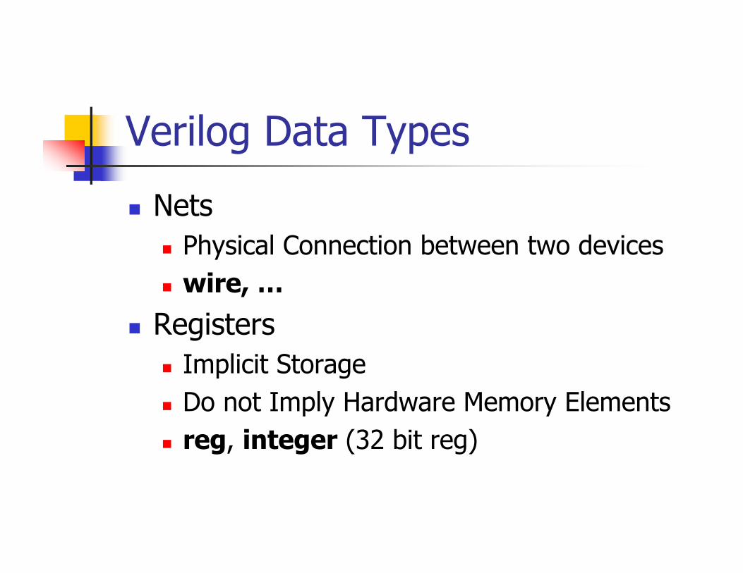
Verilog Data Types
NetsPhysical Connection between two deviceswire, …
RegistersImplicit StorageDo not Imply Hardware Memory Elementsreg, integer (32 bit reg)
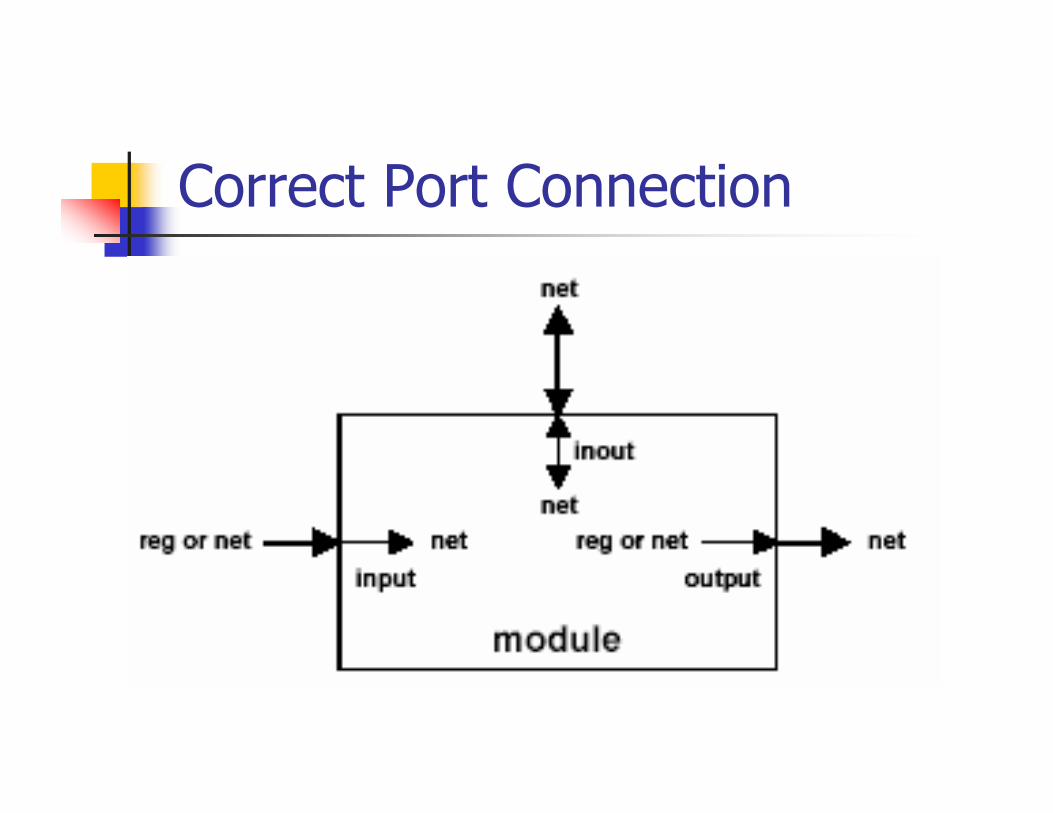
Correct Port Connection
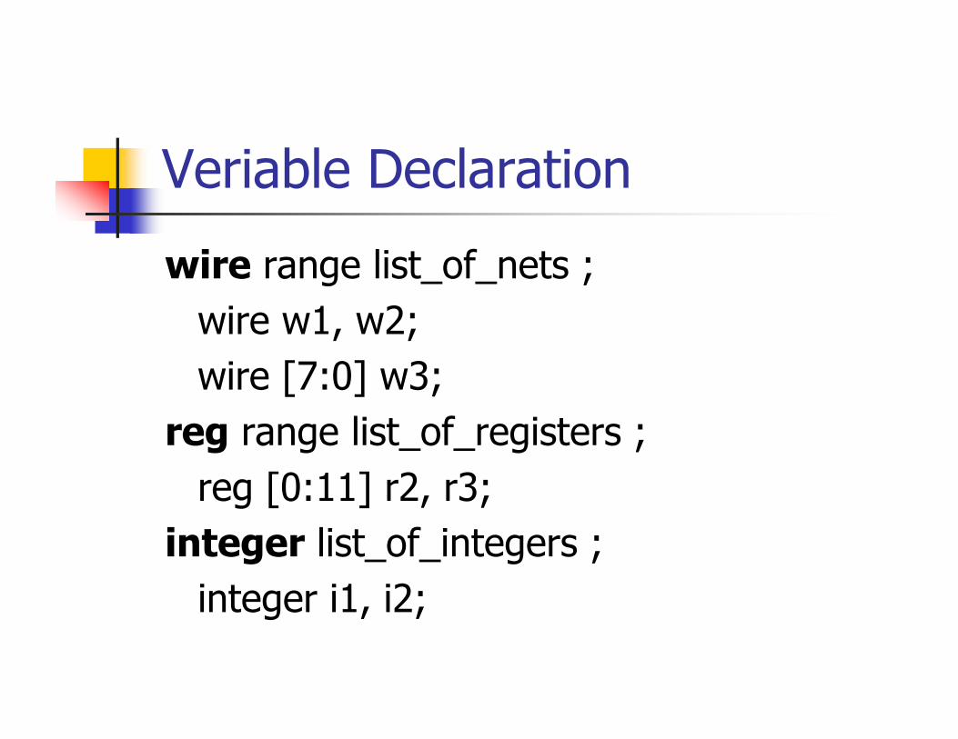
Veriable Declaration
wire range list_of_nets ;wire w1, w2;wire [7:0] w3;
reg range list_of_registers ;reg [0:11] r2, r3;
integer list_of_integers ;integer i1, i2;
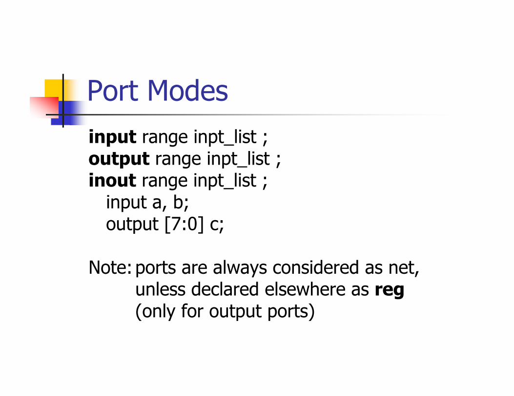
Port Modesinput range inpt_list ;output range inpt_list ;inout range inpt_list ;
input a, b;output [7:0] c;
Note:ports are always considered as net,unless declared elsewhere as reg(only for output ports)
Switch-Level Modeling
MOS Switches:nmospmos
Bidirectional Pass Switchestranif0tranif1

Example: CMOS Inverter
module cmos_inv (o1, i1);input i1;output o1;supply1 vcc;supply0 gnd;pmos p1(o1, vcc, i1);nmos n1(o1, gnd, i1);
endmodule

Gate-Level Modeling
Primitive Gatesand, nand, or, nor, xor, xnorGateType delay name (out, in1, …);
Buffer and Notbuf, notGateType delay name (out, in);
Tri-state Gatesbufif0, bufif1, notif0, notif1GateType delay name (out, in, en);
Gate Delays
1 delay#(delay)
2 delay#(rise_delay, fall_delay)
3 delay#(rise_delay, fall_delay, off_delay)
Delay Elementsmin:typical:max

Example: Full Addermodule fa (co, s, a, b, ci);
input a, b, ci;output co, s;wire w1, w2, w3;
xor #(10) x1(s, a, b, ci);and #(5, 4) a1(w1, a, b);and #(5, 4) a2(w2, a, ci);and #(5, 4) a3(w3, ci, b);or #(5:6:7) o1(co, w1, w2, w3);
endmodule

Continuous Assignment
Modeling Combinational Circuits
assign delay net_var = expression ;
assign #10 co = a&b | a&ci | b&ci; assign #12 s = a^b^ci;
Operators
ArithmeticRelationalBit-wiseLogicalConditional
ShiftReductionConcatenationReplication
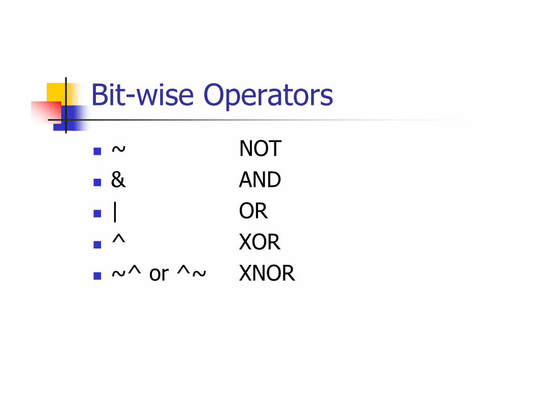
Bit-wise Operators
~ NOT& AND| OR^ XOR~^ or ^~ XNOR

Arithmetic Operators
+ Addition (unary and binary)- Subtraction (unary and binary)* Multiplication/ Division% Modulus
assign a = b + c ;
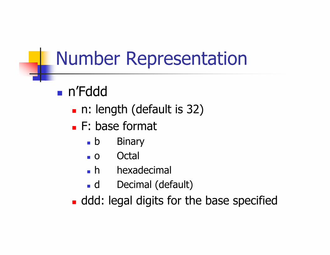
Number Representation
n’Fdddn: length (default is 32)F: base format
b Binaryo Octalh hexadecimald Decimal (default)
ddd: legal digits for the base specified
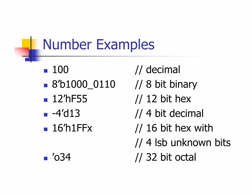
Number Examples
100 // decimal8’b1000_0110 // 8 bit binary12’hF55 // 12 bit hex-4’d13 // 4 bit decimal16’h1FFx // 16 bit hex with
// 4 lsb unknown bits’o34 // 32 bit octal

Shift Operators
<< Shift Left>> Shift Right
assign a = b << 2;assign c = d >> 1;
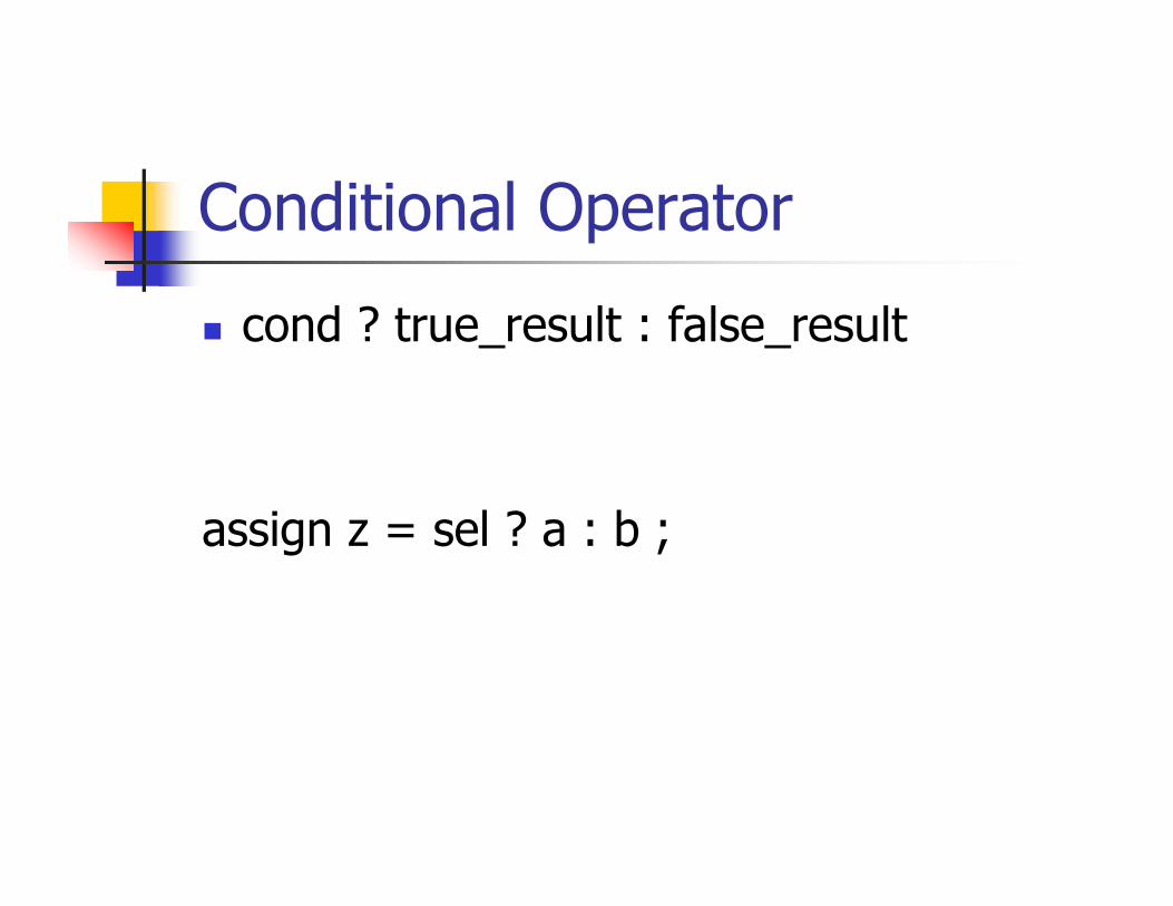
Conditional Operator
cond ? true_result : false_result
assign z = sel ? a : b ;
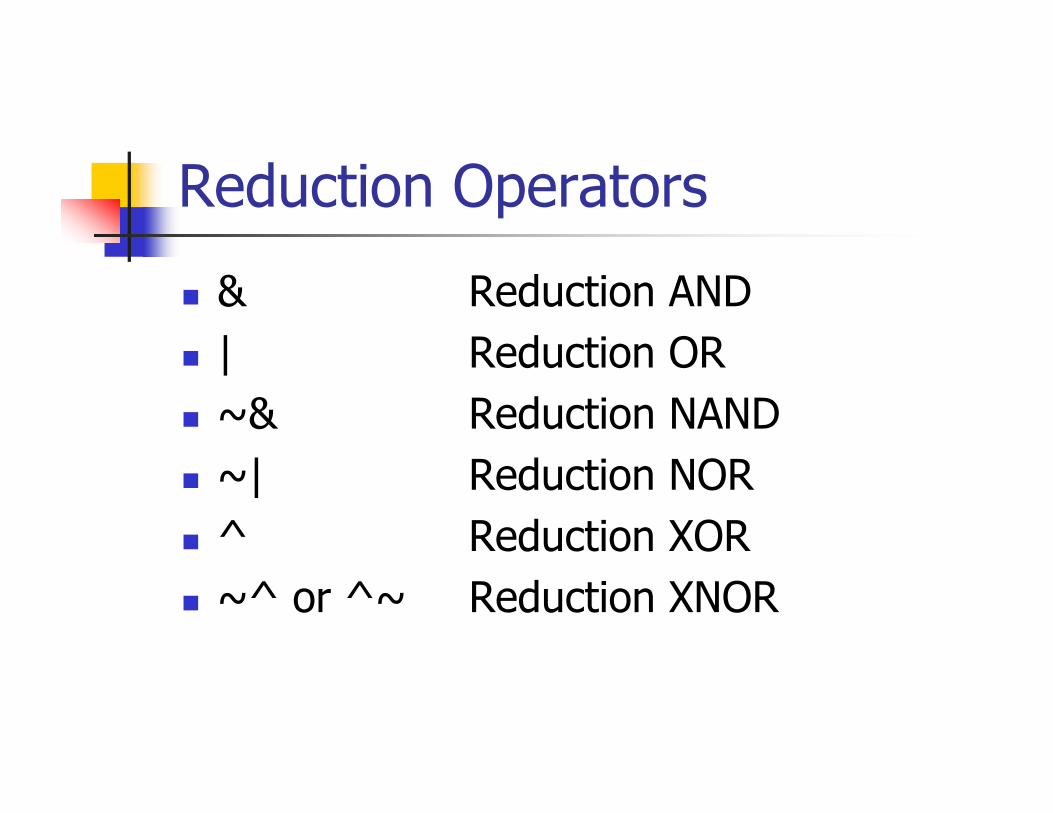
Reduction Operators
& Reduction AND| Reduction OR~& Reduction NAND~| Reduction NOR^ Reduction XOR~^ or ^~ Reduction XNOR
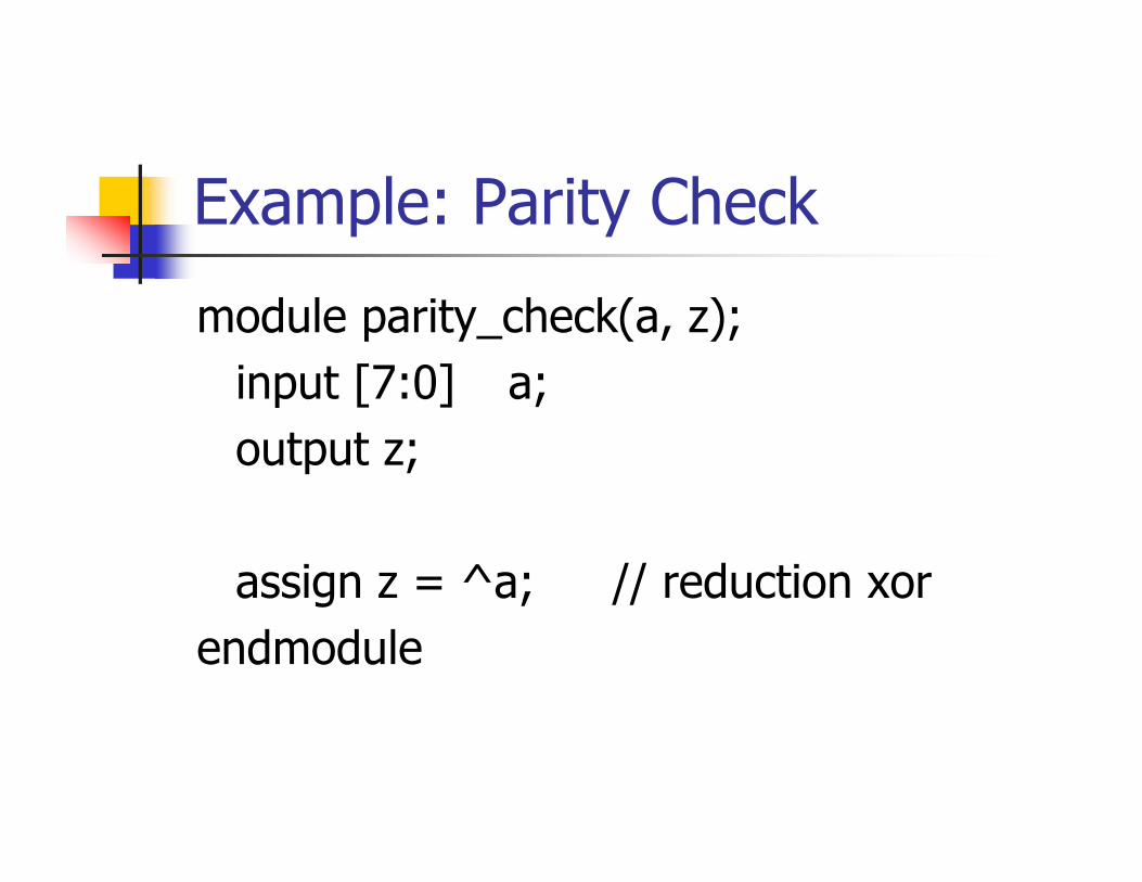
Example: Parity Check
module parity_check(a, z);input [7:0] a;output z;
assign z = ^a; // reduction xorendmodule
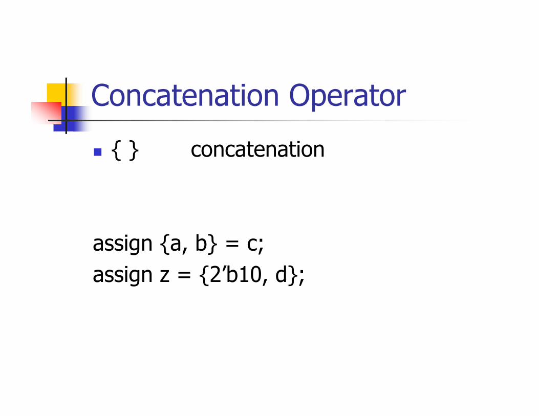
Concatenation Operator
{ } concatenation
assign {a, b} = c;assign z = {2’b10, d};

Example: Adder
module adder (co, s, a, b, ci);input [7:0] a,b;output [7:0] s;input ci; output co;
assign {co, s} = a + b + ci;
endmodule

Replication Operator
{n{item} replicate item n times
assign x = {4{4’h0}};// assign x = 16’h0000;assign z = {2{a}, 3{b}};// assign z = {a, a, b, b, b};

Relational Operators
< less than<= less than or equal> greater than>= greater than or equal== equal!= not equal
Note: return value of these operators can be 0 or 1 or x
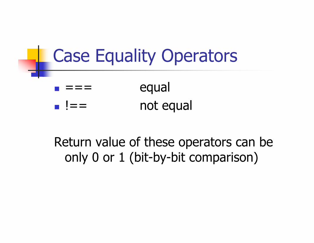
Case Equality Operators
=== equal!== not equal
Return value of these operators can be only 0 or 1 (bit-by-bit comparison)
Logical Operators
&& logical AND|| logical OR! logical NOT
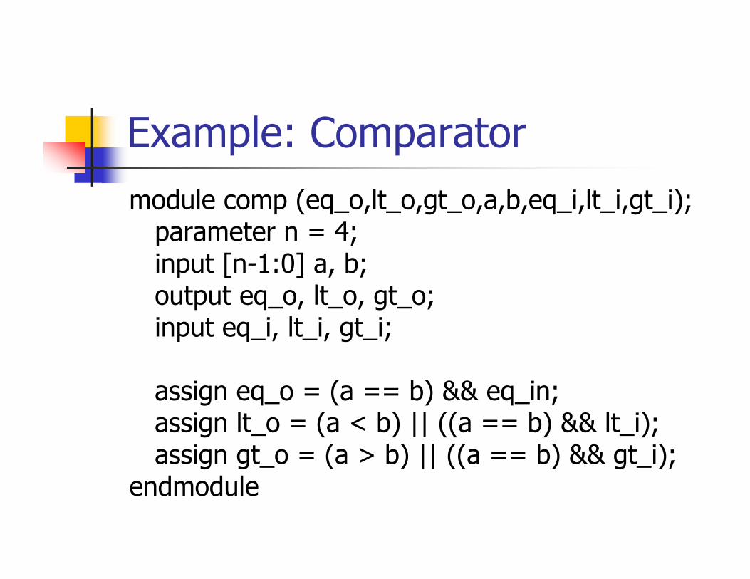
Example: Comparatormodule comp (eq_o,lt_o,gt_o,a,b,eq_i,lt_i,gt_i);
parameter n = 4;input [n-1:0] a, b;output eq_o, lt_o, gt_o;input eq_i, lt_i, gt_i;
assign eq_o = (a == b) && eq_in;assign lt_o = (a < b) || ((a == b) && lt_i);assign gt_o = (a > b) || ((a == b) && gt_i);
endmodule
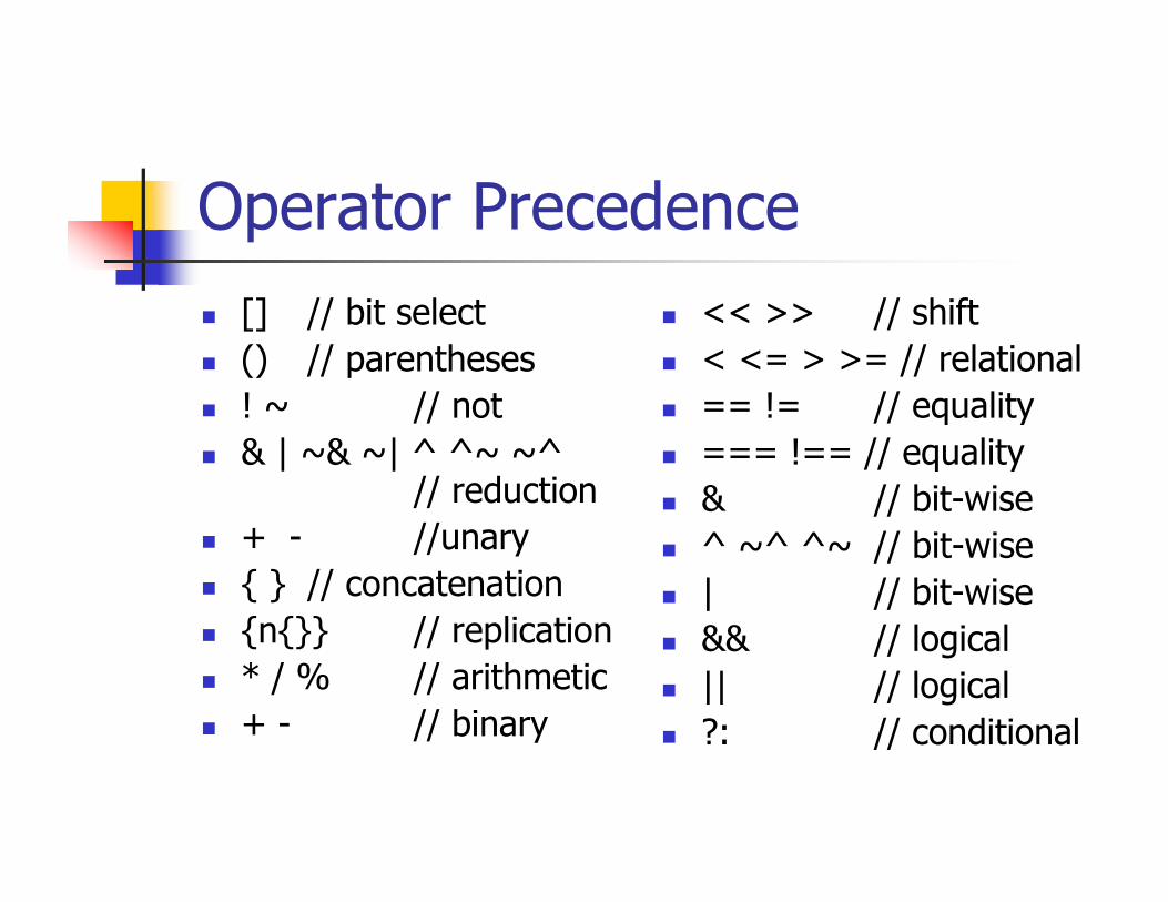
Operator Precedence[] // bit select() // parentheses! ~ // not& | ~& ~| ^ ^~ ~^
// reduction+ - //unary{ } // concatenation{n{}} // replication* / % // arithmetic+ - // binary
<< >> // shift< <= > >= // relational== != // equality=== !== // equality& // bit-wise^ ~^ ^~ // bit-wise| // bit-wise&& // logical|| // logical?: // conditional
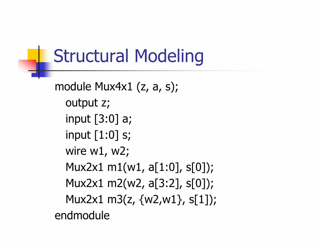
Structural Modeling
module Mux4x1 (z, a, s);output z;input [3:0] a;input [1:0] s;wire w1, w2;Mux2x1 m1(w1, a[1:0], s[0]);Mux2x1 m2(w2, a[3:2], s[0]);Mux2x1 m3(z, {w2,w1}, s[1]);
endmodule
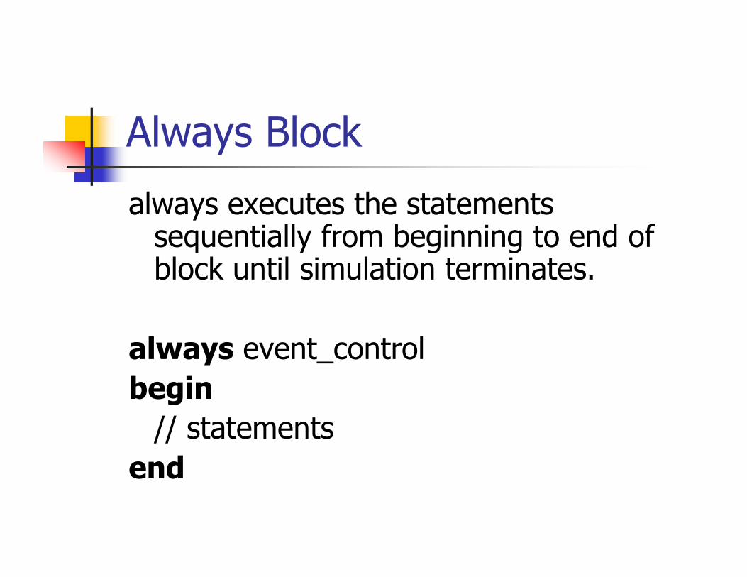
Always Block
always executes the statements sequentially from beginning to end of block until simulation terminates.
always event_controlbegin
// statementsend
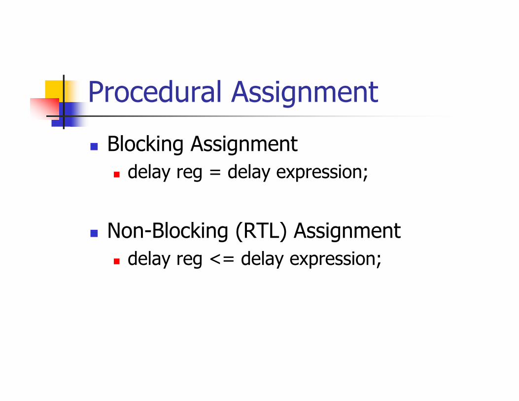
Procedural Assignment
Blocking Assignmentdelay reg = delay expression;
Non-Blocking (RTL) Assignmentdelay reg <= delay expression;
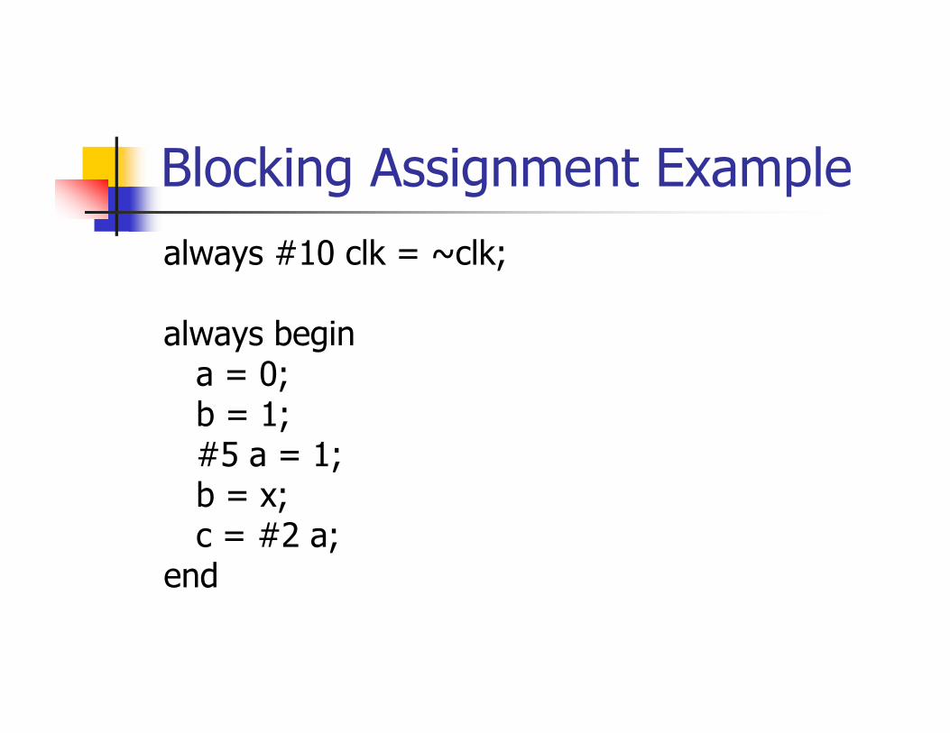
Blocking Assignment Examplealways #10 clk = ~clk;
always begina = 0;b = 1;#5 a = 1;b = x;c = #2 a;
end
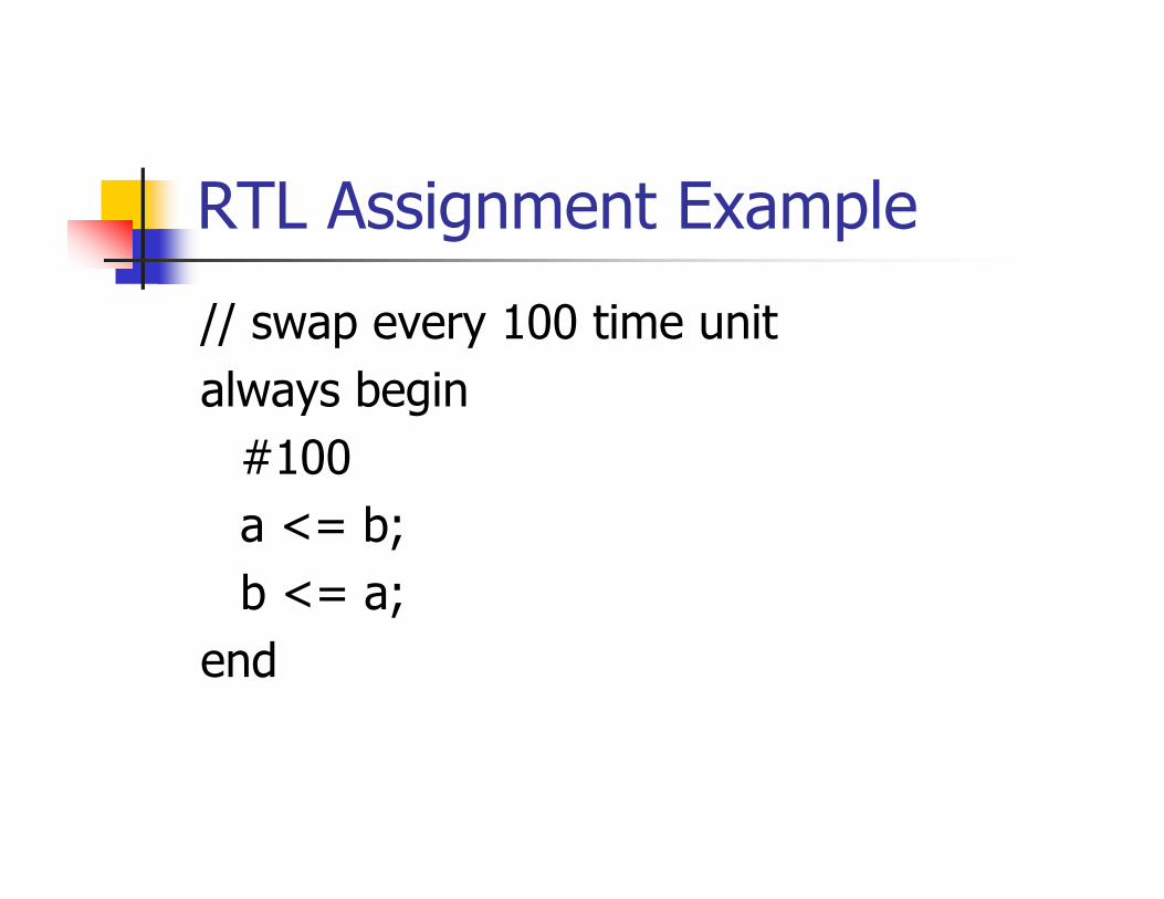
RTL Assignment Example
// swap every 100 time unitalways begin
#100 a <= b;b <= a;
end
Initial Block
begins execution of statements sequentially from the beginning of simulation and when reaches the last statement, terminates.
initialbegin
// statementsend
Initial Block Example
initial a = 0;initial begin
a = 1;b = 1;b = 0;#10 a = 0;#15 b = 1;
end
If Statementif (expression) begin
// statementsendelse if (expression) begin
// statementsend// more else if blockselse begin
// statementsend
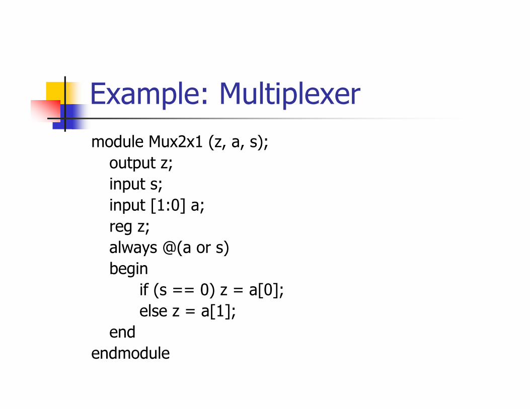
Example: Multiplexermodule Mux2x1 (z, a, s);
output z;input s;input [1:0] a;reg z;always @(a or s)begin
if (s == 0) z = a[0];else z = a[1];
endendmodule

Event Control
@( edge_control variable or …)
always @(en) …always @(en or rst) …always @(posedge clk) …always @(negedge clk) …
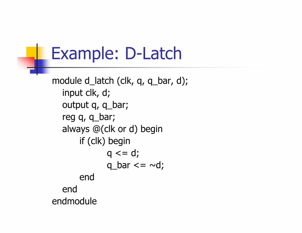
Example: D-Latchmodule d_latch (clk, q, q_bar, d);
input clk, d;output q, q_bar;reg q, q_bar;always @(clk or d) begin
if (clk) beginq <= d;q_bar <= ~d;
endend
endmodule
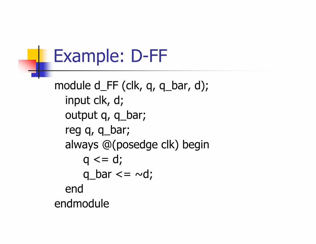
Example: D-FF
module d_FF (clk, q, q_bar, d);input clk, d;output q, q_bar;reg q, q_bar;always @(posedge clk) begin
q <= d;q_bar <= ~d;
endendmodule

Case Statementcase (expression)
chioce1:begin
// statementsend
// more choices comes heredefault:
begin// statements
endendcase
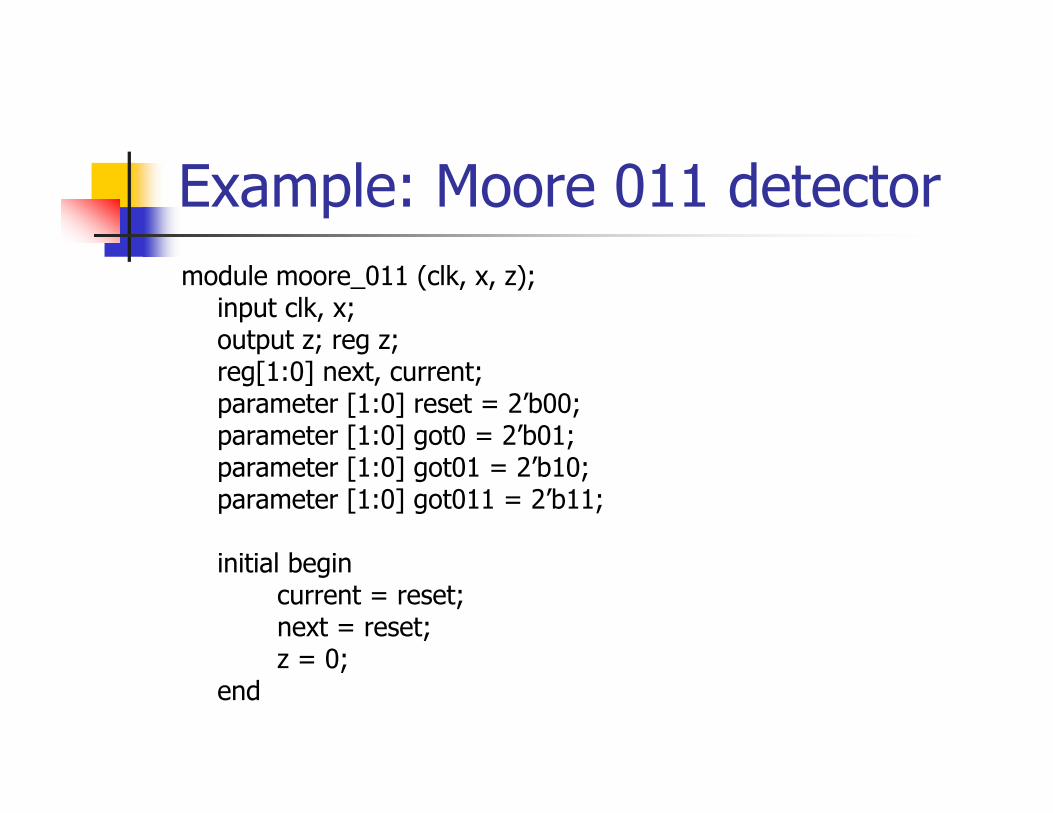
Example: Moore 011 detectormodule moore_011 (clk, x, z);
input clk, x;output z; reg z;reg[1:0] next, current;parameter [1:0] reset = 2’b00;parameter [1:0] got0 = 2’b01;parameter [1:0] got01 = 2’b10;parameter [1:0] got011 = 2’b11;
initial begincurrent = reset;next = reset;z = 0;
end
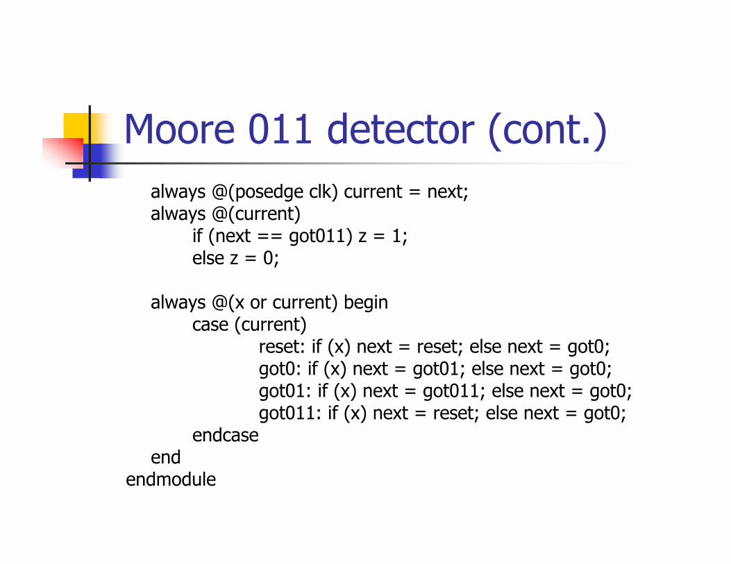
Moore 011 detector (cont.)always @(posedge clk) current = next;always @(current)
if (next == got011) z = 1;else z = 0;
always @(x or current) begincase (current)
reset: if (x) next = reset; else next = got0;got0: if (x) next = got01; else next = got0;got01: if (x) next = got011; else next = got0;got011: if (x) next = reset; else next = got0;
endcaseend
endmodule
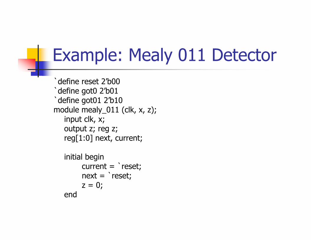
Example: Mealy 011 Detector`define reset 2’b00`define got0 2’b01`define got01 2’b10module mealy_011 (clk, x, z);
input clk, x;output z; reg z;reg[1:0] next, current;
initial begincurrent = `reset;next = `reset;z = 0;
end

Mealy 011 Detector (cont.)always @(posedge clk) current = next;
always @(current or x) z = (current == `got01 && x) ? 1 : 0;
always @(x or current)begin
case (current)`reset: if (x) next = `reset; else next = `got0;`got0: if (x) next = `got01; else next = `got0;`got01: if (x) next = `reset; else next = `got0;
endcaseend
endmodule
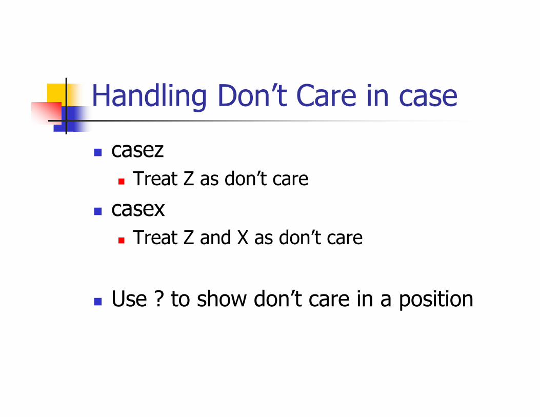
Handling Don’t Care in case
casezTreat Z as don’t care
casexTreat Z and X as don’t care
Use ? to show don’t care in a position

Example: Instruction Decode
…casez (IR)
8’b1???????: …8’b01??????: ……
endcase
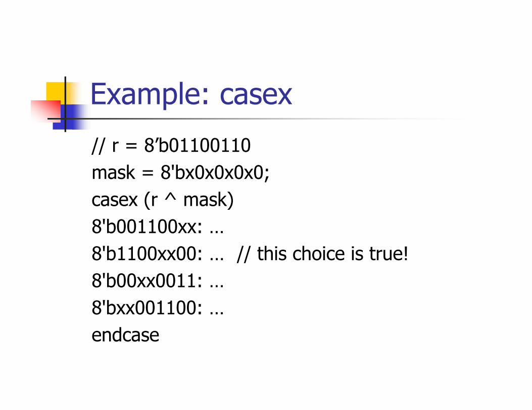
Example: casex
// r = 8’b01100110mask = 8'bx0x0x0x0;casex (r ^ mask)8'b001100xx: …8'b1100xx00: … // this choice is true!8'b00xx0011: …8'bxx001100: …endcase

Loop Statements
forevercontinuously executes statements
repeatexecute statements fixed number of times
whileexecute statements while condition is true
foris like c++ for statement
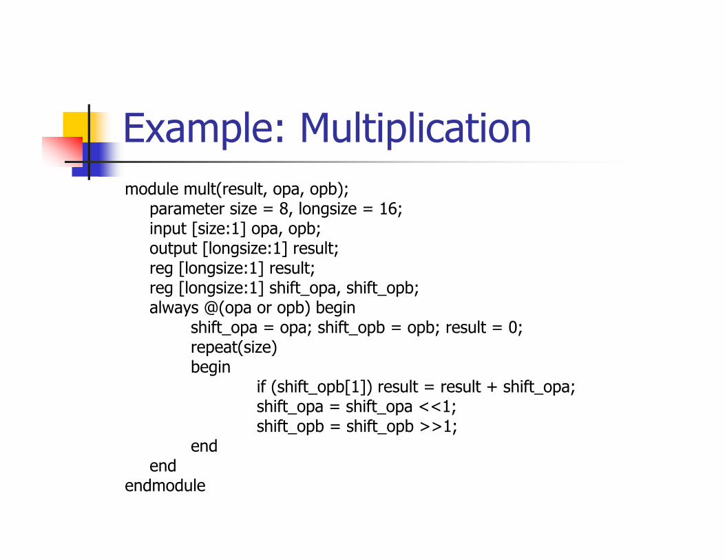
Example: Multiplicationmodule mult(result, opa, opb);
parameter size = 8, longsize = 16;input [size:1] opa, opb;output [longsize:1] result;reg [longsize:1] result;reg [longsize:1] shift_opa, shift_opb;always @(opa or opb) begin
shift_opa = opa; shift_opb = opb; result = 0;repeat(size)begin
if (shift_opb[1]) result = result + shift_opa;shift_opa = shift_opa <<1;shift_opb = shift_opb >>1;
endend
endmodule
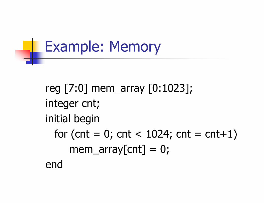
Example: Memory
reg [7:0] mem_array [0:1023];integer cnt;initial begin
for (cnt = 0; cnt < 1024; cnt = cnt+1)mem_array[cnt] = 0;
end
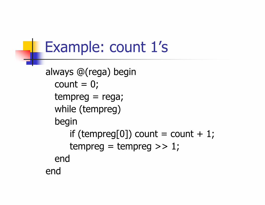
Example: count 1’s
always @(rega) begincount = 0;tempreg = rega;while (tempreg)begin
if (tempreg[0]) count = count + 1;tempreg = tempreg >> 1;
endend

Tasks
task task_name;// declare inputs and outpusbegin
// statementsend
endtask

Example: Traffic Lightmodule traffic_lights;
reg clock, red, amber, green;parameter on = 1, off = 0, red_tics = 350, amber_tics = 30, green_tics = 200;// initialize colorsInitial begin red = off; amber = off; green = off; end// sequence to control the lightsalways begin
red = on; // turn red light onlight(red, red_tics); // and wait.green = on; // turn green light onlight(green, green_tics); // and wait.amber = on; // turn amber light onlight(amber, amber_tics); // and wait.
end

Traffic Light (cont.)// wait for 'tics' positive edge clocks before turning 'color' light offtask light;
output color;input [31:0] tics;begin
repeat (tics) @(posedge clock);
color = off; // turn light offend
endtask// waveform for the clockalways begin #100 clock = ~clock; end
endmodule // traffic_lights
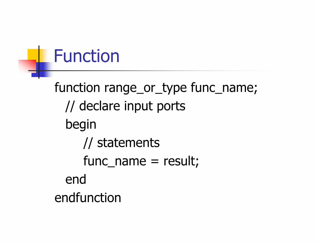
Function
function range_or_type func_name;// declare input portsbegin
// statementsfunc_name = result;
endendfunction

Function Rules
Can not contain any event controlCan not enable tasksMust contain at least one input parameterMust include an assignment to the function name (return value)
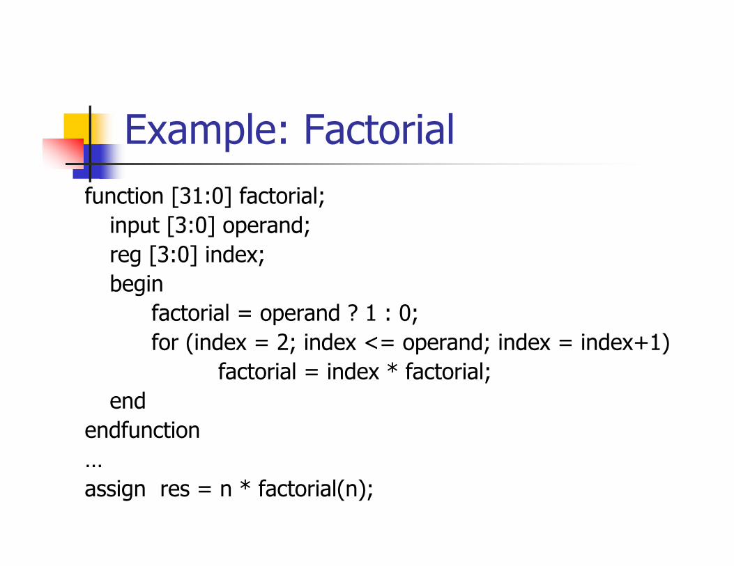
Example: Factorialfunction [31:0] factorial;
input [3:0] operand;reg [3:0] index;begin
factorial = operand ? 1 : 0;for (index = 2; index <= operand; index = index+1)
factorial = index * factorial;end
endfunction…assign res = n * factorial(n);
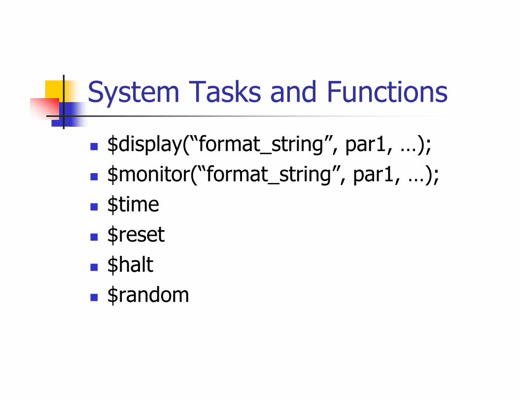
System Tasks and Functions
$display(“format_string”, par1, …);$monitor(“format_string”, par1, …);$time$reset$halt$random
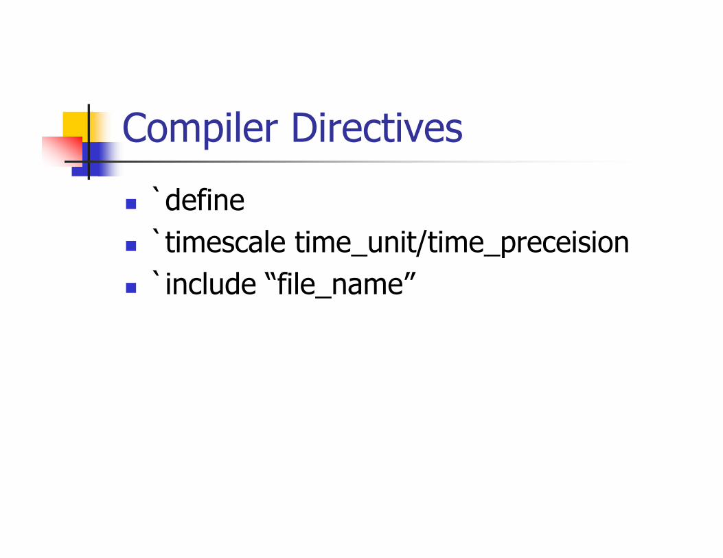
Compiler Directives
`define `timescale time_unit/time_preceision`include “file_name”