are precision hardw - av-iq dimensions.....34 general informa tion introduction the apex 2000 series...
TRANSCRIPT

PR
EC
ISIO
N H
AR
DW
AR
E
APEX 2000 SERIES

2 A P E X 2 0 0 0 S E R I E S D E V I C E S
TABLE OF CONTENTS
WIDE STILE EXIT DEVICES & TRIMS PageRim Devices ..................................................................4, 5Surface Vertical Rod Devices ........................................6, 7Mortise Devices ............................................................8, 9Wood Door Concealed Vertical Rod Devices ............14, 15Concealed Vertical Rod Devices ..............................16, 17
NARROW STILE EXIT DEVICES & TRIMSRim Devices ..............................................................10, 11Concealed Vertical Rod Devices ..............................12, 13
MULLIONSRemovable Mullion ..........................................................18Fire Labeled Removable Mullion ....................................18Key Removable Mullion ..................................................18
EXIT DEVICE OPTIONSALK Exit Alarm (Battery Operated) ................................27ALW Exit Alarm (Remote Power) ....................................27BRL Braille Touchbar ......................................................31CD Cylinder Dogging ......................................................19DE Delayed Egress ..................................................24, 25DS Door Position Switch..................................................29E Electric Rim & Mortise Devices ....................................28ELR Electric Latch Retraction ............................21, 22, 23HC Windstorm and Hurricane Code Devices ..................20LD Less Dogging ............................................................19LS Latchbolt Monitoring ..................................................29LDS Latchbolt Monitoring Double Switch ........................29TS Touchbar Monitoring ..................................................29TDS Touchbar Monitoring Double Switch ........................29WALW Weatherized Exit Alarm (Remote Power)............27WTS Weatherized Touchbar Monitoring ..........................29WTDS Weatherized Touchbar Mon. Do0uble Switch ......29Double Cylinder ................................................................9Electric Mortise Lock........................................................28
ACCESSORIES PageALK Exit Alarm Kit ..........................................................27CDK Cylinder Dogging Kit ..............................................19E Electric Lock/Unlock Kit................................................28ELR Conversion Kit ........................................................21ELR150 Power Supply and Modules..........................21,22LSK Latchbolt Monitoring Conversion Kit........................29PS160 Power Supply ......................................................25TSK Touchbar Monitoring Conversion Kit........................29Cylinders ..........................................................................19Double Cylinders Conversion Kit ....................................19Dummy Touchbar ............................................................31Miscellaneous Components ............................................31Power Transfers ..............................................................31Security Screws ..............................................................31Sex Nuts & Bolts................................................................3Shim Kit............................................................................31Strikes ..............................................................................30
ADDITION INFORMATIONBase Material and Finishes ..............................................3DE Application Charts......................................................26Device Dimensions ..........................................................33Device Minimum Stile Width......................................32, 33ELR application Charts ....................................................23Fasteners ..........................................................................3Fire Label Rating Chart....................................................35Touchbar Clearance ..........................................................2Trim Dimensions ..............................................................34
GEN
ER
AL IN
FO
RM
ATIO
N
Introduction
The Apex 2000 Series Touchbar Style Exit Device is highlyregarded by architects and end-users alike. Many of thenation’s largest healthcare and educational facilities preferthe Apex for it’s aesthetic design and efficient engineering. AllApex 2000 Series Exit Devices are UL listed for panic and firehardware and are certified to ANSI A156.3 Grade 1. Severalmodels are also certified for hurricane resistant applications.
A complete offering of mechanical and electrical options pro-vide a wide range of exit device security solutions. However,the traditional core strenghts of the product can’t be overstat-ed. Simple operation with few moving parts, manufacturedwith true ANSI/BHMA architectural finishes. The chassis isconstructed from investment cast steel and the universalmounting holes provide an easier retrofit installation.
Quiet Operation
Sound Dampeners reduce the noise associated with ExitDevice operation on the depression and return stroke of theTouchpad.
Touchbar Clearance
The Apex Wide Stile Series Exit Devices accommodate doorswith vision lites or glass windows where the vision lite framesor moldings project up to 1/4 beyond the face of the door. TheActive Case and End Cap Mounting Bracket are mounted onthe face of the door without shims or without cutting the glassmolding. These devices have a 1/4 gap between the face ofthe door and the Touchbar Assembly. This gap allows properfunctioning of the devices even on doors which are not per-fectly flat. Since the Active Case is mounted directly on theface of the door, it accommodates standard lengths ofthrough bolting screws, thumbpieces, knob & lever Trim fin-gers, and cylinder tail pieces.
Exit Device
Door (Top View)
1/4" Gap

1-5/8"
3R I E S D E V I C E S
GEN
ER
AL IN
FO
RM
ATIO
N
GENERAL INFORMATION
Base Materials
Finishes ANSI/BHMA US Aluminum Brass Bronze Stainless SteelPolished Brass, Clear Coated 605 US3Satin Brass, Clear Coated 606 US4Satin Bronze, Clear Coated 612 US10Dark Oxidized Satin Bronze 613 US10BPolished Chromium Plated 625 US26Satin Chromium Plated 626 US26DSatin Aluminum, Clear Anodized 628 US28Satin Stainless Steel 630 US32D
Finishes
ANSI/BHMA US Description605 US3 Polished Brass, Clear Coated606 US4 Satin Brass, Clear Coated612 US10 Satin Bronze, Clear Coated613 US10B Dark Oxidized Satin Bronze625 US26 Polished Chromium Plated626 US26D Satin Chromium Plated628 US28 Satin Aluminum, Clear Anodized630 US32D Satin Stainless Steel
Mullion finishes600 USP Primed for Paint689 Aluminum Paint695 Dark Bronze Paint
Fasteners
Furnished standard with machine screws and full threadwood/sheet metal screws. Specify Sex Nuts and Bolts(SNB) where recommended or required by the door manufacturer.
Sex Nuts & Bolts (not furnished std.)
Sex Nuts & Bolts are furnished with No. 10-24 x1" OHMS (1-1/2" longscrews required for guides).
Door Sizes
Stock sizes for door widths and heights are listed below. Ifrequired, cut to size in the field.
Door Widths Stock Sizes
2'-0" to 2'-6" 2'-6" *2'-7" to 3'-0" 3'-0"3'-1" to 4'-0" 4'-0"* Not available for Narrow Stile Devices.
Vertical Rod Devices
Device Door Heights Stock Sizes
Surface Vertical up to 7'-0" 7'-0"Rod Device* 7'-1" to 8'-0" 8'-0"
8'-1" to 10'-0" 10'-0"
Concealed Vertical 6'-8" to 8'-0" 8'-0"Rod Device 8'-1" to 10'-0" 10'-0"
* Surface Vertical Rods are furnished of the same material as the device. Stainless steel rods are furnished for 625, 626, 628 and 630 devices.
–– A,B,C,D,E,F,G,H –– –––– A,B,C,D,E,F,G,H –– –––– –– A,B,C,D,E,F,G,H –––– –– A,B,C,D,E,F,G,H –––– C A,B,D,E,F,G H–– C A,B,D,E,F,G H
A,E,F –– –– B,C,D,G,H–– –– –– A,B,C,D,E,F,G,H
C - Touch Bar End Caps
B - Lock Side Filler
A - Active Case Cover
E - Device Channel
F - Hinge Slide Filler
G - Device Endcap
H - Rods and Latch Covers(for Surface Vertical RodDevices)
D - Touch Bar
Hand of Doors
Security Screws
All exposed screws will be a Torx pin in tamper resistant type,machine screws only. Specify(SEC) Security Screws. CoverScrews use a T20 driver, End Cap Screws use a T25 driver.
Inside
Outside
LHRB Shown RHRB Shown

4 A P E X 2 0 0 0 S E R I E S D E V I C E S
RIM
EX
IT D
EV
ICES
Apex 2100 Series - ReversibleApex FL2100 Fire Exit Series - Reversible
Apex 21 Series – Nonhanded
RIM EXIT DEVICES
DOORS - For all types of single and double doors with a mullion. For mullions, see page 18. Available for 1-3/4" to 2-1/4" thick, up to 4'-0" wide opening. For thicker doors, consult factory. Furnished standard for 1-3/4" thick, 3'-0" wide opening.
DEVICE - Covers ANSI A115.2 (Type 161), A115.18 cylinderlock and A115.1 (Type 86) Mortise Lock preparation.
FUNCTIONS - Functions are field selectable except for the Double Cylinder option. The device is furnished for a desired function if specified. If not specified the “03” functionis furnished standard.
DOUBLE CYLINDER - Handed, “10” Function available. Requires two rim type cylinders, not furnished standard. See page 5 and 19.
BASE MATERIAL - The Cover, Touchbar, Device Channel, Lock/Hinge Side Filler and End Cap are furnished of heavywrought Brass, Bronze or Stainless Steel. 628 Devices arefurnished with Aluminum, Brass, Bronze and Stainless Steel components. See “Finish & Base Material” chart on page 3.
CHASSIS - Investment Cast Steel, Zinc Dichromated.
LATCHBOLT - Stainless Steel, Deadlocking, 3/4" throw.
STRIKES - No. S300, Investment Cast Stainless Steel, BlackPowder Coated furnished standard. No. S988, optional strike for use on Aluminum Door applications, please specify when ordering. No. S458, optional strike for use onMullion applications, please specify when ordering. For optional strike information see page 30.
DOGGING - 1/4" turn hex key dogging standard. NOTavailable on Fire Exit Hardware.
TOUCHBAR HEIGHT - 39-15/16" from floor standard. May bevaried as situation dictates.
REVERSIBLE - Reversible for all functions and Trims. Standard packaging RHRB.
UL LISTED - Panic and Fire Exit Hardware. For FIRE EXITHARDWARE Ratings see page 35. Conforms to UL10C andUBC 7-2.
ANSI/BHMA - Devices are BHMA certified for ANSI 156.3,Grade 1.
FINISHES - 605, 606, 612, 613, 625, 628, 630. For Finish description see page 3.
CYLINDERS - Rim Type, not furnished standard. Specify when required. For cylinder details see page 19.
STILE WIDTH - See Stile Information on page 32.
RETROFIT APPLICATIONS - The 2100 and FL2100 Series Devices are designed to retrofit into other manufacturers’mounting hole locations. 1700 Series Pull Trim and 4900 Series Lever Trim may also be factory set for these applications by specifying prefix “R” (e.g. 2108 R4908A). Consult factory for details.
DEVICE OPTIONS Page DE Delayed Egress ..................................................24E Electric Device ....................................................28ELR Electric Latch Retraction ....................................21FL Fire Exit Hardware ................................................4HC Windstorm and Hurricane Code Device .............20LDS Latchbolt Monitoring Double Switch ...................29LS Latchbolt Monitoring Switch ................................29TDS Touchbar Monitoring Double Switch....................29TS Touchbar Monitoring Switch ................................29WTDS Weatherized Touchbar Mon. Dbl. Switch ............29WTS Weatherized Touchbar Monitoring Switch ..........29
To specify add Prefix to Device No. (e.g. TS2103)
Suffix Description PageALK Exit Alarm: battery operated................................27ALW Exit Alarm: remote power ....................................27BRL Braille Touchbar ..................................................31CD Cylinder Dogging ................................................19DS Door Position Monitoring Switch ........................29LD Less Dogging ......................................................19SEC Security Screws ....................................................3 SNB Sex Nut and Bolt ..................................................3 WALW Weatherized Exit Alarm: remote power ..............27
To specify add Suffix to Device No. (e.g. 2103CD)
The 21 Series Device is designed to be compatible withmany manufacturers’ Access Control exterior trim. Thedevice incorporates a center driven cam to receive the tail-piece of the access control product. The tailpiece rotationrequired to retract the latch is a minimum of 50 degrees.Consult factory for details.
S300Standard
S458Optional
S988Optional

5E R I E S D E V I C E S
TR
IMSTRIMS
1700A“A” Grip
1700B“B” Grip
1700C“C” Grip
2000C“C” Grip
4900A“A” Lever
4900B“B” Lever
4900C“C” Lever
4900D“D” Lever
4900K“K” Knob
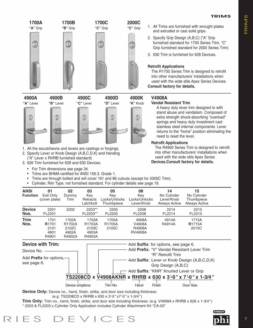
1. All Trims are furnished with wrought plates and extruded or cast solid grips.
2. Specify Grip Design (A,B,C) (“A” Grip furnished standard for 1700 Series Trim, “C” Grip furnished standard for 2000 Series Trim)
3. 630 Trim is furnished for 628 Devices.
Retrofit ApplicationsThe R1700 Series Trim is designed to retrofit into other manufacturers’ installations when used with the wide stile Apex Series Devices.
Consult factory for details.
V4908AVandal Resistant Trim
A heavy duty lever trim designed to withstand abuse and vandalism. Composed of extra strength shock-absorbing “overload” springs and heavy duty investment cast stainless steel internal components. Lever returns to the “home” position eliminating theneed to reset the lever.
Retrofit ApplicationsThe R4900 Series Trim is designed to retrofit into other manufacturers’ installations when used with the wide stile Apex Series
Devices.Consult factory for details.
1. All the escutcheons and levers are castings or forgings.2. Specify Lever or Knob Design (A,B,C,D,K) and Handing
(“A” Lever x RHRB furnished standard)3. 626 Trim furnished for 628 and 630 Devices.
• For Trim dimensions see page 34.• Trims are BHMA certified for ANSI 156.3, Grade 1.• Trims are through bolted and will cover 161 and 86 cutouts (except for 2000C Trim).• Cylinder, Rim Type, not furnished standard. For cylinder details see page 19.
ANSI 01 02 03 05 08 10* 14 15Function Double Cylinder No Cylinder No Cylinder
Exit Only Dummy Key Key Key Inside Key Lever/Knob Thumbpiece(cover plate) Trim Retracts Locks/Unlocks Locks/Unlocks Locks/Unlocks Always Always
Latchbolt Thumbpiece Lever/Knob Lever/Knob Active Active
Device 2101 2102 2103** 2105 2108 2110 2114 2115Nos. FL2101 FL2103** FL2105 FL2108 FL2110 FL2114 FL2115
Trim 1701 1702A 1703A 1705A 4908A 4908A 4914A 1715ANos. R1701 R1702A R1703A R1705A V4908A V4908A R4914A R1715A
2101 2102C 2103C 2105C R4908A R4908A 2015C4901 4902A 4903A RV4908A RV4908A
R4901 R4902A R4903A
Device with Trim: Add Suffix: for options, see page 4.Add Prefix: “V” Vandal Resistant Lever Trim
“R” Retrofit TrimAdd Suffix: Lever or Knob Design (A,B,C,D, K)
Grip Design (A,B,C)Add Suffix: “KNR” Knurled Lever or Grip
Device No.
Add Prefix for options,see page 4.
Device Only: Device no., hand, finish, strike, and door size including thickness: (e.g. TS2108CD x RHRB x 630 x S300 x 3'-0" x7'-0" x 1-3/4" )
Trim Only: Trim no., hand, finish, strike, and door size including thickness: (e.g. V4908A x RHRB x 626 x 1-3/4" )* “10” Function is handed** 2103 & FL2103 x Cylinder Only Application includes Cylinder Attachment Kit “CA-03”
TS2108CD x V4908AKNR x RHRB x 630 x S300 x 3'-0" x 7'-0" x 1-3/4"
Device w/options Trim No. Hand Finish Strike Door Size

6 A P E X 2 0 0 0 S E R I E S D E V I C E S
SU
RFA
CE V
ER
TIC
AL R
OD
EX
IT D
EV
ICES SURFACE VERTICLE ROD EXIT DEVICES
S300
S460
Apex 2200 Series - ReversibleApex FL2200 Fire Exit Series - Reversible
DOORS - For all types of single and double door applications. Available for 1-3/4" to 2-1/4" thick, up to 4'-0" wide by 10'-0" high openings. For thicker doors, consult factory. Furnished standard for 1-3/4" thick, 3'-0"wide by 7'-0" high openings.
DEVICE - Covers ANSI A115.2 (Type 161), A115.18 cylinder lock and A115.1 (Type 86) Mortise Lock preparation.
FUNCTIONS - Functions are field selectable. The device is furnished for a desired function if specified. If not specified the “03” function is furnished standard.
BASE MATERIAL - The Covers, Touchbar, Device Channel, Lock/Hinge Side Filler, Vertical Rods and End Cap are furnished of heavy wrought Brass, Bronze or Stainless Steel. US28 Devices are furnished withAluminum, Brass, Bronze and Stainless Steel components. See “Finish & Base Material” chart on page 3.
CHASSIS - Investment Cast Steel, Zinc Dichromated.
TOP LATCHBOLT - Stainless Steel, Deadlocking, 3/4" throw.
REVERSIBLE - Reversible for all functions and trims. Standard packing RHRB.
UL LISTED - Panic and Fire Exit Hardware. For FIRE EXIT HARDWARE Ratings see page 35. Conforms to UL10C and UBC 7-2.
ANSI/BHMA - Devices are BHMA certified for ANSI 156.3,Grade 1.
FINISHES - 605, 606, 612, 613, 625, 628, 630. For finish description see page 3.
CYLINDERS - Rim type, not furnished standard. Specify when required. For cylinder details see page 19.
STILE WIDTH - See Stile Information on page 32.
LESS BOTTOM ROD (LBR) OPTION - Specify suffix “LBR” (e.g. 2208LBR). See UL FIRE LABEL RATING chart on page 35. Fire Rated Devices include FB277 Fire Bolt Assembly.
RETROFIT APPLICATIONS - The 2200 and FL2200 Series Devices are designed to retrofit into other manufacturers’ mounting hole locations. 1700 Series Pull Trimand 4900 Series Lever Trim may also be factory set for these applications by specifying prefix “R” (e.g. 2208 R4908A).
BOTTOM BOLT - Steel plated, independent action 5/8"throw, with adjustment range to suit 3/4" door undercut.
TOP STRIKE - No. S300 Surface applied, Investment Cast Stainless Steel, Black Powder Coated furnished standard. For optional strikes see page 30.
BOTTOM STRIKE - No. S460, Flush mounted, Steel, Black Powder Coated.
DOGGING - 1/4" turn hex key dogging standard. NOTavailable on Fire Exit Hardware.
TOUCHBAR HEIGHT - 39-15/16" from floor standard. Specify required height if other than standard.
Apex 22 Series - ReversibleThe 22 Series Device is designed to be compatible with many manufacturers’ Access Control exterior trim. The device incorporates a center driven cam to receive the tailpiece of the access control product. The tailpiece rotation required to retract the latch is a minimum of 50 degrees.
Consult factory for details.
Prefix Description PageE Electric Device ..................................................28ELR Electric Latch Retraction..................................21FL Fire Exit Hardware..............................................6HC Windstorm and Hurricane Code Device ........20LS Latchbolt Monitoring Switch ............................29TDS Touchbar Monitoring Double Switch ..............29TS Touchbar Monitoring Switch ............................29WTDS Weatherized Touchbar Mon. Dbl Switch ........29WTS Weatherized Touchbar Mon. Switch ..............29To specify add Prefix to Device No. (e.g. TS2203)
Suffix Description PageALK Exit Alarm: battery operated ............................27ALW Exit Alarm: remote power ................................27BRL Braille Touchbar................................................31CD Cylinder Dogging..............................................19DS Door Position Monitoring Switch ....................29LBR Less Bottom Rod................................................6LD Less Dogging............................................19SEC Security Screws..................................................3SNB Sex Nut and Bolt ................................................3TMB Transom Bracket ..............................................31WALW Weatherized Exit Alarm: remote power..........27To specify add Prefix to Device No. (e.g. TS2203)
DEVICE OPTIONS
7E R I E S D E V I C E S
TR
IMSTRIMS
1700A“A” Grip
1700B“B” Grip
1700C“C” Grip
2000C“C” Grip
4900A“A” Lever
4900B“B” Lever
4900C“C” Lever
4900D“D” Lever
4900K“K” Knob
1. All Trims are furnished with wrought plates and extruded or cast solid grips.
2. Specify Grip Design (A,B,C) (“A” Grip furnished standard for 1700 Series Trim, “C” Grip furnished standard for 2000 Series Trim)
3. 630 Trim is furnished for 628 Devices.
Retrofit ApplicationsThe R1700 Series Trim is designed to retrofit into other manufacturers’ installations when used with the wide stile Apex Series Devices.
Consult factory for details.
V4908AVandal Resistant Trim
A heavy duty lever trim designed to withstand abuse and vandalism. Composed of extra strength shock-absorbing “overload” springs and heavy duty investment cast stainless steel internal components. Lever returns to the “home” position eliminating theneed to reset the lever.
Retrofit ApplicationsThe R4900 Series Trim is designed to retrofit into other manufacturers’ installations when used with the wide stile Apex Series
Devices.Consult factory for details.
1. All the escutcheons and levers are castings or forgings.2. Specify Lever or Knob Design (A,B,C,D,K) and Handing
(“A” Lever x RHRB furnished standard)3. 626 Trim furnished for 628 and 630 Devices.
• For Trim dimensions see page 34.• Trims are BHMA certified for ANSI 156.3, Grade 1.• Trims are through bolted and will cover 161 and 86 cutouts (except for 2000C Trim).• Cylinder, Rim Type, not furnished standard. For cylinder details see page 19.
ANSI 01 02 03 05 08 14 15Function Exit Only Dummy Key Key Key No Cylinder No Cylinder
(cover plate) Trim Retracts Locks/Unlocks Locks/Unlocks Lever/Knob ThumbpieceLatchbolt Thumbpiece Lever/Knob Always Active Always Active
Device 2201 2202 2203** 2205 2208 2214 2215Nos. FL2201 FL2203** FL2205 FL2208 FL2214 FL2215
Trim 1701 1702A 1703A 1705A 4908A 4914A 1715ANos. R1701 R1702A R1703A R1705A V4908A R4914A R1715A
2101 2102C 2103C 2105C R4908A 2015C4901 4902A 4903A RV4908A
R4901 R4902A R4903A
Device with Trim: Add Suffix: for options, see page 6.Add Prefix: “V” Vandal Resistant Lever Trim
“R” Retrofit TrimAdd Suffix: Lever or Knob Design (A,B,C,D,K)
Grip Design (A,B,C)Add Suffix: “KNR” Knurled Lever or Grip
Device No.
Add Prefix for options,see page 6.
Device Only: Device no., hand, finish, strike, and door size including thickness: (e.g. TS2208CD x RHRB x 630 x 3'-0" x7'-0" x 1-3/4" )
Trim Only: Trim no., hand, finish, strike, and door size including thickness: (e.g. V4908A x RHRB x 626 x 1-3/4" )* 2203 & FL2203 x Cylinder Only Application includes Cylinder Attachment Kit “CA-03”
TS2208CD x V4908AKNR x RHRB x 630 x 3'-0" x 7'-0" x 1-3/4"
Device w/options Trim No. Hand Finish Door Size

8 A P E X 2 0 0 0 S E R I E S D E V I C E S
MO
RTIS
E EX
IT D
EV
ICES
Apex 2300 Series - HandedApex FL2300 Fire Exit Series - Handed
MORTISE EXIT DEVICES
DOORS - For all types of single and double door applications. Available for 1-3/4" to 2-1/4" thick, up to 4-0" wide opening. For thicker door, consult factory. Furnished standard for1-3/4" thick, 3'-0" wide opening.
DEVICE - Covers ANSI A115.1 (Type 86) Mortise Lock preparation.
DOUBLE CYLINDER - Handed, “10” Function available. Requires one rim type cylinder and one 1-1/4" long mortise type cylinder, not furnished standard. See page 9 and 19.
BASE MATERIAL - The Cover, Touchbar, Device Channel,Lock/Hinge Side Filler and End Cap are furnished of heavy wrought Brass, Bronze or Stainless Steel. US28 Devices are furnished with Aluminum, Brass, Bronze and Stainless Steel components. See “Finish & Base Material” chart on page 3.
CHASSIS - Investment Cast Steel, Zinc Dichromated.
DOGGING - 1/4" turn hex key dogging standard. NOT availableon Fire Exit Hardware.
TOUCHBAR HEIGHT - 39-15/16" from floor standard.
HANDED - Specify hand when ordering as RHRB or LHRB. Touchbar Assembly, Mortise Lock and Trim may be reversed in the field. For reversibility of complete device, mortise strikeis required for the other hand.
UL LISTED - Panic and Fire Exit Hardware. For FIRE EXITHARDWARE Ratings see page 35. Conforms to UL10C and UBC 7-2.
ANSI/BHMA - Devices are BHMA certified for ANSI 156.3, Grade 1.
FINISHES - 605, 606, 612, 613, 625, 628, 630. For finish description see page 3.
STILE WIDTH - See Stile Information on page 32.
CYLINDERS - Mortise type, not furnished standard. For cylinder details see page 19.
RETROFIT APPLICATIONS - The 2300 and FL2300 Series Devices are designed to retrofit into other manufacturers’mounting hole locations. 1700 Series Pull Trim and 4900 Series Lever Trim may also be factory set for these appli-cations by specifying prefix “R” (e.g. 2308 R4908A).
Consult factory for details.
Exit Series - HandedFits doors machined per ANSI A115.1 (Type 86) Mortise Lock preparation.
BACKSET - 2-3/4".
CASE - Wrought Steel, Zinc Dichromate finish.
LOCK FRONT PLATE - 8" x 1-1/4" Bronze, Brass or Stainless Steel, pivots for beveled or square edged doors.
LATCHBOLT - Stainless Steel, Deadlocking, 3/4" throw, anti-friction.
GUARDBOLT - Stainless Steel, sliding type.
FINISHES - LOCK FRONT PLATE and STRIKE605, 606, 612, 613, 625, 630. 630 furnished for 626 and 628 locks. For finish description see page 3.
STRIKES - No. S982, handed curved lip strike furnished standard. For optional strikes see page 30.
LOCK NO.• M303: 01, 02 & 03 functions.• M308: 05, 08, 14 & 15 functions.• M310: 10 function.
NOTE - For Mortise Lock dimensions see page 28. For Mortise Lock with Electrical options see page 28.
Prefix Description PageWTDS Weatherized Touchbar Mon. Dbl. Switch ............29WTS Weatherized Touchbar Monitoring Switch ..........29
Suffix Description PageALK Exit Alarm: battery operated................................27ALW Exit Alarm: remote power ....................................27BRL Braille Touchbar ..................................................31CD Cylinder Dogging ................................................19DS Door Position Monitoring Switch ........................29LD Less Dogging ......................................................19SEC Security Screws ....................................................3 SNB Sex Nut and Bolt ..................................................3 WALW Weatherized Exit Alarm: remote power ..............27
To specify add Suffix to Device No. (e.g. 2303CD)
Prefix Description Page DE Delayed Egress ..................................................24E Electric Lock/Unlock............................................28ELR Electric Latch Retraction ....................................21FL Fire Exit Hardware ................................................8HC Windstorm and Hurricane Code Device ............20LS Latchbolt Monitoring, “03” Function ..............28, 29LS Latchbolt and Trim locked or unlocked
monitoring, “08” Function..............................28, 29TDS Touchbar Monitoring Double Switch ..................29TS Touchbar Monitoring Switch................................29
To specify add Prefix to Device No. (e.g. TS2303)
S982
DEVICE OPTIONS

9E R I E S D E V I C E S
TR
IMSTRIMS
1700A“A” Grip
1700B“B” Grip
1700C“C” Grip
2000C“C” Grip
4900A“A” Lever
4900B“B” Lever
4900C“C” Lever
4900D“D” Lever
4900K“K” Knob
1. All Trims are furnished with wrought plates and extruded or cast solid grips.
2. Specify Grip Design (A,B,C) (“A” Grip furnished standard for 1700 Series Trim, “C” Grip furnished standard for 2000 Series Trim)
3. 630 Trim is furnished for 628 Devices.
Retrofit ApplicationsThe R1700 Series Trim is designed to retrofit into other manufacturers’ installations when used with the wide stile Apex Series Devices.
Consult factory for details.
V4908AVandal Resistant Trim
A heavy duty lever trim designed to withstand abuse and vandalism. Composed of extra strength shock-absorbing “overload” springs and heavy duty investment cast stainless steel internal components. Lever returns to the “home” position eliminating theneed to reset the lever.
Retrofit ApplicationsThe R4900 Series Trim is designed to retrofit into other manufacturers’ installations when used with the wide stile Apex Series
Devices.Consult factory for details.
1. All the escutcheons and levers are castings or forgings.2. Specify Lever or Knob Design (A,B,C,D,K) and Handing
(“A” Lever x RHRB furnished standard)3. 626 Trim furnished for 628 and 630 Devices.4. All Lever Trims, M4908K and 4914K are Handed, Specify Hand.
• For Trim dimensions see page 34.• Trims are BHMA certified for ANSI 156.3, Grade 1.• Trims are through bolted and will cover 161 and 86 cutouts (except for 2000C Trim).• Cylinder 1-1/4" long Mortise Type, not furnished standard. For cylinder details see page 19.
ANSI 01 02 03 05 08 10* 14 15Function Exit Only Dummy Key Key Key Double Cylinder No Cylinder No Cylinder
(cover plate) Trim Retracts Locks/Unlocks Locks/Unlocks Inside Key Lever/Knob ThumbpieceLatchbolt Thumbpiece Lever/Knob Locks/Unlocks Always Active Always
Lever/Knob Active
Device 2301 2302 2303** 2305 2308 2310 2314 2315Nos. FL2301 FL2303** FL2305 FL2308 FL2310 FL2314 FL2315
Trim 1701 1702A 1703A 1705A 4908A 4908A 4914A 1715ANos. R1701 R1702A R1703A R1705A V4908A V4908A R4914A R1715A
2101 2102C 2103C 2105C R4908A R4908A 2015C4901 4902A 4903A RV4908A RV4908A
R4901 R4902A R4903A
Device with Trim: Add Suffix: for options, see page 8.Add Prefix: “V” Vandal Resistant Lever Trim
“V” Vandal Resistant Lever Trim“R” Retrofit Trim
Add Suffix: Lever or Knob Design (A,B,C,D,K)Grip Design (A,B,C)
Add Suffix: “KNR” Knurled Lever or Grip
Device No.
Add Prefix for options,see page 8.
Device Only: Device no., hand, finish, strike, and door size including thickness: (e.g. TS2108CD x RHRB x 630 x S982 x 3'-0" x7'-0" x 1-3/4" )
Trim Only: Trim no., hand, finish, strike, and door size including thickness: (e.g. V4908A x RHRB x 626 x 1-3/4" )
TS2308CD x V4908AKNR x RHRB x 630 x S982 x 3'-0" x 7'-0" x 1-3/4"
Device w/options Trim No. Hand Finish Strike Door Size

10 A P E X 2 0 0 0 S E R I E S D E V I C E S
NA
RR
OW
R
IM EX
IT D
EV
ICES
Apex 2400 Series - Non HandedApex FL2400 Fire Exit Series - Non Handed
RIM EXIT DEVICES
DOORS - For all types of single and double doors with a mullion. For mullions, see page 18. Available for 1-3/4" to 2-1/4" thick, up to 4'-0" wide opening. For thicker door, consult factory. Furnished standard for 1-3/4" thick, 3'-0"wide opening.
FUNCTIONS - A Universal Exit Device. Add Trim for desired function.
BASE MATERIAL - The Cover, Touchbar, Device Channel, Lock/Hinge Side Filler and End Cap are furnished of heavywrought Brass, Bronze or Stainless Steel. US28 Devices are furnished with Aluminum, Brass, Bronze and StainlessSteel components. See “Finish & Base Material” chart on page 3.
CHASSIS - Investment Cast Steel, Zinc Dichromated.
LATCHBOLT - Stainless Steel, Deadlocking, 3/4" throw.
STRIKES - No. S988, standard for Aluminum Door applications, Black Powder Coated Stainless Steel Roller Strike. No. S458, optional for Hollow Metal Door or Mullionapplications, please specify when ordering. For optional strike information see page 30.
DOGGING - 1/4" turn hex key dogging standard. NOT available on Fire Exit Hardware.
TOUCHBAR HEIGHT - 39-15/16" from floor standard. May be varied as situation dictates.
UL LISTED - Panic and Fire Exit Hardware. For FIRE EXITHARDWARE Ratings see page 35. Conforms to UL10C and UBC 7-2.
ANSI/BHMA - Devices are BHMA certified for ANSI 156.3, Grade 1.
FINISHES - 605, 606, 612, 613, 625, 628, 630. For finish description see page 3.
CYLINDERS - Rim Type for “03” function, Mortise type for “08” function. Use 1-1/4" long standard mortise cylinder. Cylinders are not furnished standard. Specify when required. For cylinder details see page 19.
STILE WIDTH - See Stile Information on page 33.
DEVICE OPTIONSPrefix Description Page
DE Delayed Egress ..................................................24ELR Electric Latch Retraction ....................................21FL Fire Exit Hardware ..............................................10TDS Touchbar Monitoring Double Switch....................29TS Touchbar Monitoring Switch ................................29WTDS Weatherized Touchbar Mon. Dbl. Switch ............29WTS Weatherized Touchbar Monitoring Switch ..........29
To specify add Prefix to Device No. (e.g. TS2403)
Suffix Description PageALK Exit Alarm: battery operated................................27ALW Exit Alarm: remote power ....................................27BRL Braille Touchbar ..................................................31CD Cylinder Dogging ................................................19DS Door Position Monitoring Switch ........................29LD Less Dogging ......................................................19SEC Security Screws ....................................................3SNB Sex Nut and Bolt ..................................................3 WALW Weatherized Exit Alarm: remote power ..............27
To specify add Suffix to Device No. (e.g. 2403CD)
S458Optional
S988Standard

11E R I E S D E V I C E S
TR
IMSTRIMS
2000C“C” Grip
2900A“A” Lever
2900B“B” Lever
2900C“C” Lever
2900D“D” Lever 1. All the escutcheons and levers are castings
or forgings.
2. For Lever Trim specify Lever Design (A, B, C, D) and Handing (“A” Lever RHRB furnished standard).
3. For 2900 Series Trim, 626 finish is furnishedfor 628 and 630 Devices.
4. 2000 Series Trim is furnished with a wroughtplate and extruded solid “C” Grip.
• For Trim dimensions see page 34.• Trims are BHMA certified for ANSI 156.3, Grade 1.• Trims are through bolted.• Cylinder, not furnished standard – Rim type for “03” function, 1-1/4"long mortise type for “08” function.
For cylinder details see page 19.
ANSI 01 02 03 08 14Function Exit Only Dummy Key Key No Cylinder
(cover plate) Trim Retracts Locks/Unlocks LeverLatchbolt Lever Always Active
Device 2401 2402 2403* 2408 2414Nos. FL2401 FL2403* FL2408 FL2414
Trim 2901 2902A 2903A 2908A 2914ANos. 2001 2002C 2003C
Device with Trim: Add Suffix: for options, see page 10.
Add Suffix: Lever Design (A,B,C,D)Grip Design (C)
Add Suffix: “KNR” Knurled Lever
Device No.
Add Prefix for options,see page 10.
Device Only: Device no., hand, finish, strike, and door size including thickness: (e.g. TS2408CD x RHRB x 630 x S988 x 3'-0" x7'-0" x 1-3/4" )
Trim Only: Trim no., hand, finish, strike, and door size including thickness: (e.g. 2908A x RHRB x 626 x 1-3/4" )
* 2403 & FL2403 x Cylinder Only Application includes Cylinder Attachment Kit “NCA-03”
TS2408CD x 2908AKNR x RHRB x 630 x S988 x 3'-0" x 7'-0" x 1-3/4"
Device w/options Trim No. Hand Finish Strike Door Size

12 A P E X 2 0 0 0 S E R I E S D E V I C E S
NA
RR
OW
C
ON
CEA
LED
V
ER
TIC
AL R
OD
EX
IT D
EV
ICES NARROW CONCEALED VERTICLE ROD EXIT DEVICES
S519
S460
Apex 2600 Series - ReversibleApex FL2600 Fire Exit Series - Reversible
DOORS - For all types of single and double door applications. Available for 1-3/4" to 2-1/4" thick, up to 4'-0" wide by 10'-0" high openings. For thicker doors, consult factory. Furnished standard for 1-3/4" thick, 3'-0"wide by 6'-8" to 8'-0" high openings.
FUNCTIONS - A Universal Exit Device. Add Trim for desired function.
BASE MATERIAL - Side Filler and End Cap are furnished of heavy wrought Brass, Bronze or Stainless Steel. 628 Devices are furnished with Aluminum, Brass, Bronze and Stainless Steel components. See “Finish & Base Material” chart on page 3.
CHASSIS - Lock Stile Assembly - Investment Cast Steel, Zinc Dich-romated.
TOP LATCHBOLT - Stainless Steel, Deadlocking, 3/4" throw.
TOP STRIKE - No. S519 Surface applied, Investment Cast Stainless Steel, Black Powder Coated.
BOTTOM STRIKE - No. S460, Flush mounted, Steel, BlackPowder Coated.
DOGGING - 1/4" turn hex key dogging standard.NOT available on Fire Exit Hardware.
TOUCHBAR HEIGHT - 39-15/16" from floor standard. Specify required height if other than standard.
UL LISTED - Panic and Fire Exit Hardware. For FIRE EXIT HARDWARE Ratings see page 35. Conforms to UL10C and UBC 7-2.
ANSI/BHMA - Devices are BHMA certified for ANSI 156.3, Grade 1.
FINISHES - 605, 626, 612, 613, 625, 628, 630. For finish description see page 3.
CYLINDERS - Rim Type for “03” function, 1-1/4" Long Mortise Type for “08” function. Cylinders are not furnishedstandard. Specify when required. For cylinder details see page 19.
BOTTOM BOLT - Steel plated, independent action 5/8"throw, with adjustment range to suit 3/4" door undercut.
CENTER CHASSIS - Steel plated, heavy wrought Steel Assembly with lock in place Top and Bottom Latch Adjustors. Adjustment is accessible through the door after installation.
STILE WIDTH - See Stile Information on page 33.
LESS BOTTOM ROD (LBR) OPTION - Specify suffix “LBR” (e.g. 2603LBR). See UL FIRE LABEL RATINGChart on page 35. Fire Rated Devices include FB277Fire Bolt Assembly.
Prefix Description PageDE Delayed Egress ................................................24ELR Electric Latch Retraction..................................21FL Fire Exit Hardware............................................12TDS Touchbar Monitoring Double Switch ..............29TS Touchbar Monitoring Switch ............................29WTDS Weatherized Touchbar Mon. Dbl. Switch ......29WTS Weatherized Touchbar Mon. Switch ..............29
To specify add Prefix to Device No. (e.g. TS2603)
Suffix Description PageALK Exit Alarm: battery operated ............................27ALW Exit Alarm: remote power ................................27BRL Braille Touchbar................................................31CD Cylinder Dogging..............................................19DS Door Position Monitoring Switch ....................29LBR Less Bottom Rod..............................................12LD Less Dogging............................................19SEC Security Screws..................................................3 SNB Sex Nut and Bolt ................................................3WALW Weatherized Exit Alarm: remote power..........27
To specify add Prefix to Device No. (e.g. TS2603)
DEVICE OPTIONS

13E R I E S D E V I C E S
TR
IMSTRIMS
2900A“A” Lever
2900B“B” Lever
2900C“C” Lever
2900D“D” Lever 1. All the escutcheons and levers are castings
or forgings.
2. Specify Lever Design (A, B, C, D) and Handing (“A” Lever RHRB furnished standard).
3. 626 finish is furnished for 628 and 630 Devices.
• For Trim dimensions see page 34.• Trims are BHMA certified for ANSI 156.3, Grade 1.• Trims are through bolted.• Cylinder, not furnished standard – Rim type for “03” function, 1-1/4"long mortise type for “08” function.
For cylinder details see page 19.
ANSI 01 02 03 08 14Function Exit Only Dummy Key Key No Cylinder
(cover plate) Trim Retracts Locks/Unlocks LeverLatchbolt Lever Always Active
Device 2601 2602 2603* 2608 2614Nos. FL2601 FL2603* FL2608 FL2614
Trim 2901 2902A 2903A 2908A 2914ANos.
Device with Trim: Add Suffix: for options, see page 12.
Add Suffix: Lever Design (A,B,C,D)
Add Suffix: “KNR” Knurled Lever
Device No.
Add Prefix for options,see page 12.
Device Only: Device no., hand, finish, strike, and door size including thickness: (e.g. TS2608CD x RHRB x 630 x 3'-0" x7'-0" x 1-3/4" )
Trim Only: Trim no., hand, finish, strike, and door size including thickness: (e.g. 2908A x RHRB x 626 x 1-3/4" )
* 2603 & FL2603 x Cylinder Only Application includes Cylinder Attachment Kit “NCA-03”
TS2608CD x 2908AKNR x RHRB x 630 x 3'-0" x 7'-0" x 1-3/4"
Device w/options Trim No. Hand Finish Door Size

14 A P E X 2 0 0 0 S E R I E S D E V I C E S
WO
OD
D
OO
R C
ON
CEA
LED
V
ER
TIC
AL R
OD
EX
IT D
EV
ICES WOOD DOOR CONCEALED VERTICLE ROD EXIT DEVICES
BOTTOM STRIKE - No. S460 Flush mounted, Steel, Black Powder Coated.
DOGGING - 1/4 turn hex key dogging standard. NOTavailable on Fire Exit Hardware.
TOUCHBAR HEIGHT - 39-15/16 from floor standard. Specify required height if other than standard.
REVERSIBLE - Reversible for all functions and trims. Standard packaging RHRB.
UL LISTED - Panic and Fire Exit Hardware. For FIRE EXITHARDWARE Ratings see page 35. Conforms to UL10C and UBC 7-2.
ANSI/BHMA - Devices are BHMA certified for ANSI 156.3, Grade 1.
FINISHES - 605, 606, 612, 613, 625, 628, 630. For finish description see page 3.
CYLINDERS - Rim Type, not furnished standard. Specify when required. For cylinder details see page 19.
Suffix Description PageALK Exit Alarm: battery operated ............................27ALW Exit Alarm: remote power ................................27BRL Braille Touchbar................................................31CD Cylinder Dogging..............................................19DS Door Position Monitoring Switch ....................29LBR Less Bottom Rod..............................................14LD Less Dogging............................................19SEC Security Screws..................................................3SNB Sex Nut and Bolt ................................................3WALW Weatherized Exit Alarm: remote power..........27
To specify add Prefix to Device No. (e.g. TS2703)
Apex 2700 Series - ReversibleApex FL2700 Fire Exit Series - Reversible
DOORS - For all types of single and double door applications. Available for 1-3/4" to 2-1/4" thick, up to 4'-0" wide by 10'-0" high openings. For thicker doors, consult factory. Furnished standard for 1-3/4" thick, 3'-0"wide by 6'-8" to 8'-0" high openings.
FUNCTIONS - A Universal Exit Device. Add Trim for desired function.
BASE MATERIAL - Side Filler and End Cap are furnished of heavy wrought Brass, Bronze or Stainless Steel. 628 Devices are furnished with Aluminum, Brass, Bronze and Stainless Steel components. See “Finish & Base Material” chart on page 3.
CHASSIS - Lock Stile Assembly - Investment Cast Steel, Zinc Dich-romated.
VERTICAL RODS - Steel, plated. Top Rod is adjustable from 6'-8" to 8'-0" or from 8'-1" to 10'-0". Additional adjustments are available through the lock front filler.
TOP LATCHBOLT - Stainless Steel, Deadlocking, 3/4"throw.
BOTTOM BOLT - Steel plated, independent action 5/8"throw, with adjustment range to suit 3/4 door undercut.
TOP STRIKE - No. S519 Surface applied, Investment Cast Stainless Steel, Black Powder Coated.
STILE WIDTH - See Stile Information on page 32.
LESS BOTTOM ROD (LBR) OPTION - Specify suffix “LBR” (e.g. 2703LBR). See UL FIRE LABEL RATINGChart on page 35. Fire Rated Devices include FB277Fire Bolt Assembly.
Prefix Description PageDE Delayed Egress ................................................24E Electric Device ..................................................28ELR Electric Latch Retraction..................................21FL Fire Exit Hardware............................................14LS Latchbolt Monitoring Switch ............................29TDS Touchbar Monitoring Double Switch ..............29TS Touchbar Monitoring Switch ............................29WTDS Weatherized Touchbar Mon. Dbl. Switch ......29WTS Weatherized Touchbar Mon. Switch ..............29
To specify add Prefix to Device No. (e.g. TS2703)
DEVICE OPTIONS
S519
S460

15E R I E S D E V I C E S
TR
IMSTRIMS
1700A“A” Grip
1700B“B” Grip
1700C“C” Grip
2000C“C” Grip
4900A“A” Lever
4900B“B” Lever
4900C“C” Lever
4900D“D” Lever
4900K“K” Knob
1. All Trims are furnished with wrought plates and extruded or cast solid grips.
2. Specify Grip Design (A,B,C) (“A” Grip furnished standard for 1700 Series Trim, “C” Grip furnished standard for 2000 Series Trim)
3. 630 Trim is furnished for 628 Devices.
V4908AVandal Resistant Trim
A heavy duty lever trim designed to withstand abuse and vandalism. Composed of extra strength shock-absorbing “overload” springs and heavy duty investment cast stainless steel internal components. Lever returns to the “home” position eliminating theneed to reset the lever.
1. All the escutcheons and levers are castings or forgings.2. Specify Lever or Knob Design (A,B,C,D,K) and Handing
(“A” Lever x RHRB furnished standard)3. 626 Trim furnished for 628 and 630 Devices.
• For Trim dimensions see page 34.• Trims are BHMA certified for ANSI 156.3, Grade 1.• Trims are through bolted and will cover 161 and 86 cutouts (except for 2000C Trim).• Cylinder, Rim Type, not furnished standard. For cylinder details see page 19.
ANSI 01 02 03 05 08 14 15Function Exit Only Dummy Key Key Key No Cylinder No Cylinder
(cover plate) Trim Retracts Locks/Unlocks Locks/Unlocks Lever/Knob ThumbpieceLatchbolt Thumbpiece Lever/Knob Always Active Always Active
Device 2701 2702 2703** 2705 2708 2714 2715Nos. FL2701 FL2703** FL2705 FL2708 FL2714 FL2715
Trim 1701 1702A 1703A 1705A 4908A 4914A 1715ANos. 2001 2002C 203C 2005C V4908A 2015C
4901 4902A 4903A
Device with Trim: Add Suffix: for options, see page 14.
Add Prefix: “V” Vandal Resistant Lever Trim
Add Suffix: Lever or Knob Design (A,B,C,D,K)Grip Design (A,B,C)
Add Suffix: “KNR” Knurled Lever or Grip
Device No.
Add Prefix for options,see page 14.
Device Only: Device no., hand, finish, strike, and door size including thickness: (e.g. TS2708CD x RHRB x 630 x 3'-0" x7'-0" x 1-3/4" )
Trim Only: Trim no., hand, finish, strike, and door size including thickness: (e.g. V4908A x RHRB x 626 x 1-3/4" )* 2703 & FL2703 X Cylinder Only Application includes Cylinder Attachment Kit “CA-03”.
TS2708CD x V4908AKNR x RHRB x 630 x 3'-0" x 7'-0" x 1-3/4"
Device w/options Trim No. Hand Finish Door Size

16 A P E X 2 0 0 0 S E R I E S D E V I C E S
CO
NC
EA
LED
V
ER
TIC
AL R
OD
EX
IT D
EV
ICES CONCEALED VERTICLE ROD EXIT DEVICES
TOP STRIKE - No. S519 Surface applied, Investment Cast Stainless Steel, Black Powder Coated.
BOTTOM STRIKE - No. S460 Flush mounted, Steel, Black Powder Coated.
DOGGING - 1/4" turn hex key dogging standard. NOT available on Fire Exit Hardware.
TOUCHBAR HEIGHT - 39-15/16" from floor standard. Specify required height if other than standard.
REVERSIBLE - Reversible for all functions and trims. Standard packaging RHRB.
UL LISTED - Panic and Fire Exit Hardware. For FIRE EXITHARDWARE Ratings see page 35. Conforms to UL10C and UBC 7-2.
ANSI/BHMA - Devices are BHMA certified for ANSI 156.3, Grade 1.
FINISHES - 605, 606, 612, 613, 625, 628, 630. For Finish description see page 3.
CYLINDERS - Rim Type, not furnished standard. Specify when required. For cylinder details see page 19.
Suffix Description PageALK Exit Alarm: battery operated ............................27ALW Exit Alarm: remote power ................................27BRL Braille Touchbar................................................31CD Cylinder Dogging ..............................................9DS Door Position Monitoring Switch ....................29LBR Less Bottom Rod..............................................16LD Less Dogging............................................19SEC Security Screws..................................................3SNB Sex Nut and Bolt ..............................................3WALW Weatherized Exit Alarm: remote power..........27
To specify add Prefix to Device No. (e.g. TS2803)
Apex 2800 Series - ReversibleApex FL2800 Fire Exit Series - Reversible
DOORS - For all types of single and double door applications. Available for 1-3/4" to 2-1/4" thick, up to 4'-0" wide by 10-0 high openings. For thicker doors, consult factory. Furnished standard for 1-3/4" thick, 3'-0"wide by 6'-8" to 8'-0" high openings.
FUNCTIONS - Functions are field selectable. The device is furnished for a desired function if specified. If not specified the “03” function is furnished standard.
BASE MATERIAL - The Cover, Touchbar, Device Channel, Lock/Hinge Side Filler and End Cap are furnished of heavy wrought Brass, Bronze or Stainless Steel. US28 Devices are furnished with Aluminum, Brass, Bronze and Stainless Steel components. See “Base Material and Finish Chart” on page 3.
CHASSIS - Lock Stile Assembly - Investment Cast Steel, Zinc Dichromated.
VERTICAL RODS - Steel, plated. Top Rod is adjustable from 6'-8" to 8'-0" or from 8'-1" to 10'-0".
TOP LATCHBOLT - Stainless Steel, Deadlocking, 3/4"throw.
BOTTOM BOLT - Steel plated, independent action 5/8 throw, with adjustment range to suit 3/4 door undercut.
CENTER CHASSIS - Steel plated, heavy wrought Steel Assembly with lock in place Top and Bottom Latch Adjustors. Adjustment accessible through the door after installation.
STILE WIDTH - See Stile Information on page 32.
LESS BOTTOM ROD (LBR) OPTION - Specify suffix“LBR” (e.g. 2808LBR). See UL FIRE LABEL RATINGchart on page 35. Fire Rated Devices include FB277Fire Bolt Assembly.
Prefix Description PageDE Delayed Egress ..............................................24E Electric Device ..................................................28ELR Electric Latch Retraction..................................21FL Fire Exit Hardware............................................16HC Windstorm and Hurricane Code Device ........20LS Latchbolt Monitoring Switch ............................29TDS Touchbar Monitoring Double Switch ..............29TS Touchbar Monitoring Switch ............................29WTDS Weatherized Touchbar Mon. Dbl. Switch ......29WTS Weatherized Touchbar Mon. Switch ..............29
To specify add Prefix to Device No. (e.g. TS2803)
DEVICE OPTIONS
S519
S460

17E R I E S D E V I C E S
TR
IMSTRIMS
1700A“A” Grip
1700B“B” Grip
1700C“C” Grip
C03Cast Plate
“Pull by others”
The CVR2803 with “Pull byOther” must be specifiedwith No. C03 CylinderAttachment Trim to securethe Rim Cylinder. Specifyfinish.
4900A“A” Lever
4900B“B” Lever
4900C“C” Lever
4900D“D” Lever
4900K“K” Knob
1. All Trims are furnished with wrought plates and extruded or cast solid grips.
2. Specify Grip Design (A,B,C) (“A” Grip furnished standard for C1700 Series Trim)
3. 630 Trim is furnished for 628 Devices.
V4908AVandal Resistant Trim
A heavy duty lever trim designed to withstand abuse and vandalism. Composed of extra strength shock-absorbing “overload” springs and heavy duty investment cast stainless steel internal components. Lever returns to the “home” position eliminating theneed to reset the lever.
1. All the escutcheons and levers are castings or forgings.2. Specify Lever or Knob Design (A,B,C,D,K) and Handing
(“A” Lever x RHRB furnished standard)3. 626 Trim furnished for 628 and 630 Devices.
• For Trim dimensions see page 34.• Trims are BHMA certified for ANSI 156.3, Grade 1.• Trims are through bolted and will cover 161 and 86 cutouts (except for 2000C Trim).• Cylinder, Rim Type, not furnished standard. For cylinder details see page 19.
ANSI 01 02 03 05 08 14 15Function Exit Only Dummy Key Key Key No Cylinder No Cylinder
(cover plate) Trim Retracts Locks/Unlocks Locks/Unlocks Lever/Knob ThumbpieceLatchbolt Thumbpiece Lever/Knob Always Active Always Active
Device 2801 2802 2803** 2805 2808 2814 2815Nos. FL2801 FL2803** FL2805 FL2808 FL2814 FL2815
Trim C1701 C1702A C03 1705A 4908A 4914A C1715ANos. 4901 4902A C1703A V4908A
4903A
Device with Trim: Add Suffix: for options, see page 16.Add Prefix: “V” Vandal Resistant Lever Trim
“V” Vandal Resistant Lever Trim“V” Vandal Resistant Lever Trim
Add Suffix: Lever or Knob Design (A,B,C,D,K)Grip Design (A,B,C)
Add Suffix: “KNR” Knurled Lever or Grip
Device No.
Add Prefix for options,see page 16.
Device Only: Device no., hand, finish, strike, and door size including thickness: (e.g. TS2808CD x RHRB x 630 x 3'-0" x7'-0" x 1-3/4" )
Trim Only: Trim no., hand, finish, strike, and door size including thickness: (e.g. V4908A x RHRB x 626 x 1-3/4" )
TS2808CD x V4908AKNR x RHRB x 630 x 3'-0" x 7'-0" x 1-3/4"
Device w/options Trim No. Hand Finish Door Size

18 A P E X 2 0 0 0 S E
MU
LLIO
NS MULLIONS
Removable MullionsThe Mullion is used to adapt a double door opening to two single door openings with Rim Exit Devices.When the full width of an opening is required, the mullion may be removed.
KEY REMOVABLE MULLION (KR) - Provides a secure yet quick & easy means of removing the 822 or FL822 Mullion. The mullion can be reinstalled and locked without the need of the key.
STOCK SIZE - For openings 8'-0" high. For openings less than 8'-0" high the mullion can be cut down. For openings greater than 8'-0" high using the 822, KR822 or 811 mullions, consult factory.
FINISHES - 600, 689, 695. For Finish description see page 3.
822, FL822, KR822, FLKR822 MullionU.L. LISTED - FL822 and FLKR822 listed for Fire Exit Hardware. For FIRE LABEL RATING Chart see
page 35.
MULLION - 2" x 3" Steel.
MULLION BASE - Investment Cast Steel, 2" wide 3-1/2" deep. Furnished with steel anchors for concretefloors.
INTERLOCK - Black Powder Coated Investment Cast Stainless Steel. Furnished standard for FL822 and FLKR822 Mullions. It interlocks the mullion to the Rim Active Case and S300 or S301 Strike.
STABILIZERS - Black Powder Coated Steel. Stabilizers are furnished standard for FL822 and FLKR822 Mullions.
MULLION CAP SPACER - Minimum width 3-1/2". For 2-1/4" frame spacer specify part no. MCS822.
822, FL822 MULLION CAP - MC822 Investment Cast Steel, 4" wide 3-5/8" deep.
KR822, FLKR822 KEY REMOVABLE MULLION CAP ASSEMBLY - Investment Cast Steel - can be ordered to convert existing 822 or FL822 mullions to Keyed Removable Mullions. Retrofits to the hole pattern of an MC822 Mullion Cap. To order specify KMC822 or KMC822F. For wire run information, please consult factory.
CYLINDER - not furnished standard - Rim Type required. See page 19 for cylinder details.
MULLION - 2" x 3" Steel Mullion is reinforced with a 1-1/2" x 2-1/2" 11 gage Steel Tube. MC822 or KMC822 Mullion Cap and MB822 Mullion Base Assemblies are used to secure the HC Mullion in the door opening. The S1447 Interlock must be used to Interlock the Active Case with the Strike and is furnished standard with the HC822 Mullion.
MullionCapMC822
MullionBaseMB822
MullionCapMC811
MullionBaseMB811
Key RemovableMullion CapKMC822(Rim Cylinder required)
Mullion Cap SpacerMCS822
InterlockS1447
StabilizerST989
HC822, HCKR822 Mullion
MULLION - 2" x 2" Steel Mullion.
MULLION CAP - Cast 4-1/2" wide x 2-5/16", furnished with machine screws for metal frames.
MULLION BASE - Cast 2" wide x 2-3/4", furnished with sheet metal screws and plastic anchors.
811 Mullion
To Order: Specify Mullion No. Height Finish (e.g. 822 x 8'-0" x 600)

19R I E S D E V I C E S
CY
LIN
DER
FU
NC
TIO
NSCYLINDER FUNCTIONS
Cylinder Dogging Kit
NOTE - The channel fillers are different lengths for narrowand wide stile devices. “NCDK” - Narrow Cylinder Dogging Kit.
To Order: specify CDK-3, NCDK-3 for up to 3-0 and CDK4, NCDK-4 for devices up to 4-0.
Cylinder Dogging
Available for all Apex Series Devices except Fire Exit Hardware and Delayed Egress Devices.
Cylinder Dogging provides the ability to lock down the touchbar with a key cylinder so the door can be used in the push/pull mode. To order, specify suffix “CD” (e.g. 2103CD). Requires the use of a 1-1/4 mortise cylinder, not furnished standard. Specify when required.
Less Dogging
Available for all Apex Series Devices except Fire Exit
Double Cylinder Kits - Handed
The kit is available to convert 2103, FL2103, 2303 and FL2303 devices to 2110, FL2110, 2310 and FL2310 in the field.
Rim Kit No. RDC10 - Includes locking assembly, cylinder assembly, cylinder collar and active case cover. Two rim typecylinders are required, not furnished standard.
Mortise Kit No. MDC10 - Includes M310 Mortise Lock, extension assembly, cylinder bracket, cylinder collar and active case cover. One rim type and one 1-1/4" long mortise type cylinder required, not furnished standard.
To Order: Specify Hand and Finish(e.g. RDC10 RHRB 630)
Cylinders
Cylinders are not furnished standard with the device or trim.BEST 7 pin standard. Available in 612 finish. Specify Type and finish when ordering. (e.g. 1E74 x 630)
Double Cylinder - Handed(“10” Function)
The Double Cylinder option is available on the Wide Stile Rim and Mortise Exit Devices. The inside key cylinder locks or unlocks the outside Trim and the outside key cylinder retracts the latchbolt. Specify Outside Trim with “08” function.
When only the inside key cylinder is required to lock or unlock the outside trim and no outside cylinder operation is necessary, specify outside trim with “14” function.
Cylinders - Not furnished standard.Rim Devices - Two rim type required.Mortise Devices - One rim type and one 1-1/4" long mortisetype required.
Type Device No. Trim No.
Rim 2110, FL2110 x 4908A, V4908A, 4914AMortise 2310, FL2310 x M4908A, VM4908A, M4914A
To Order: Specify Hand and Finish(e.g. 2110 4908A RHRB 630)
2110 Rim Device - Handed
2310 Mortise Device - Handed
1-1/8"
1-1/4"
1/16"
1/4"
Rim Cylinder - 1E74
1-1/8"
1-1/4"
5/16"
3/4"
Mortise Cylinder - 3E74
To convert from hex key dogging to cylinder dogging in the field, a cylinder dogging kit is available. The kit consists of a channel filler, blocking ring, cylinder locator and lock nut. Requires the use of a 1-1/4" mortise cylinder, not furnished standard. Specify when required.

20 A P E X 2 0 0 0 S E R I E S D E V I C E S
Compliance - HC2100, HC2200, HC2300, HC2800 SeriesDevices and HC822, KRHC822 Mullions comply with the FloridaBuilding Code including the High Velocity Hurricane Zone. TheMiami-Dade County Product Control Division has approved thesedevices to be used in Miami-Dade County and other areas whereallowed by the Authority Having Jurisdiction (AHJ). ProductControl NOA No. 05-1102-12 is issued for these devices whichexpires on September 30, 2009.
To see the NOA documentation online: http://www.miamidade.gov/buildingcode/online_product_search.asp and type in the NOAnumber: 05-1102-12 under the Product Search Application link.
ANSI Function Device No. Trim No.
HC2101, FLHC2101HC2201, FLHC2201HC2301, FLHC2301HC2801, FLHC2801
Exit Only(cover plate01
170120014901
HC2100 , HC2200, HC2300, HC2800 SeriesDevices HC822,KRHC822 Mullions
The Hurricane Devices have passed the structural tests as perSouth Florida Building Code Protocol. These tests are designed toprovide sufficient resistance to high wind forces and wind- bornedebris. The devices provide a high level of security for door open-ings even if hurricane rated door components are not required. Abrief description of the test is provided below.
Static Air Pressure Test - Simulates wind loading by evenly dis-tributing air pressure to the face of the door assembly in positiveand negative directions. The door assembly must not have exces-sive deflection or deformation and must remain secure in thechamber.
Missile Impact Test - Simulates impacts created by wind drivendebris by impacting the exterior face of the doors with a 2 x 4 boardat 50 feet per second. The board must not pass through the doorsand the doors must remain secure in the chamber.
Cyclic Wind Pressure Test - Simulates wind gusts by repeatingcycles of positive and negative air pressure to determine that theintegrity of the door assembly is not compromised with the MissileImpact Test. The door assembly must not have excessive deflec-tion or deformation and must remain secure in the chamber.
Component Approval - These devices are approved as compo-nents to be used with any 16 gage Single or a Pair of Hollow MetalDoors and Frames holding a current Notice of Acceptance (NOA).The lowest Design Pressure Rating of the doors or componentsshall apply.
• Trims with the Prefix “M” are for 2300 Series Devices only.• 2000 Series Trim not available with 2800 Series Device.• “10” Function is handed.
Rim Exit Devices and Trims ....................................................4,5Surface Vertical Rod Devices and Trims ................................6,7Mortise Devices and Trims ......................................................8,9Concealed Vertical Rod Devices and Trims ......................16,17HC822 & HCKR822 Mullions ..................................................18
Door Device DesignSINGLE DOOR Opening Series Pressure
4'-0" W8'-0" H
Rim Device HC2100 80 PSF
4'-0" W8'-0" H
Mortise Device HC2300 60 PSF
4'-0" W8'-0" H
Surface VerticalRod Device
HC2200 80 PSF
4'-0" W8'-0" H
Concealed VerticalRod Device
HC2800 80 PSF
PAIR OF DOORS
8'-0" W8'-0" H 80 PSF
8'-0" W8'-0" H
60 PSF
8'-0" W8'-0" H
Two SurfaceVertical Rod DeviceMortise Device xConcealed VerticalRod Device
Two Rim Deviceswith Mullion
80 PSF
8'-0" W8'-0" H
Two Concealed Vertical Rod Device 80 PSF
WIN
DSTO
RM
A
ND
H
UR
RIC
AN
E C
OD
E D
EV
ICES WINDSTORM AND HURRICANE CODE DEVICES
HC2100 xHC822,KRHC822HC2200 xHC2200
HC2300 xHC2800
HC2800 xHC2800
HC2103, FLHC2103HC2203, FLHC2203HC2303, FLHC2303HC2803, FLHC2803
Key RetractsLatchbolt03
C03170320034903M4903A
HC2105, FLHC2105HC2205, FLHC2205HC2305, FLHC2305HC2805, FLHC2805
Key Locks /UnlocksThumbpiece
05
1705A2005AM1705AM2005A
HC2108, FLHC2108HC2208, FLHC2208HC2308, FLHC2308HC2808, FLHC2808
HC2114, FLHC2114HC2214, FLHC2214HC2314, FLHC2314HC2814, FLHC2814
Key Locks /UnlocksLever / Knob
08
4908AV4908AM4908AVM4908A
HC2110, FLHC2110HC2310, FLHC2310
Double CylinderInside Key Locks / UnlocksLever / Knob
104910AV4910AM4910AVM4910A
No CylinderLever / KnobAlways Active
14 4914AM4914A
HC2115, FLHC2115HC2215, FLHC2215HC2315, FLHC2315HC2815, FLHC2815
No CylinderThumbpieceAlways Active
15
1715A2015CM1715AM2015C
HC2102HC2202HC2302HC2802
Dummy Trim021702A2002C4902A
Device Specifications and Options page

21E R I E S D E V I C E S
ELEC
TR
IC LA
TC
H R
ETR
AC
TIO
N
ELECTRIC LATCH RETRACTION
ELR150 Series Power Supply
The ELR150 Series is a power supply REQUIRED to control ELR Devices. The power supply contains a Motherboard that willaccept up to four plug-in Control Modules. Each Control Module(part #CM150-08, see page 22) controls one ELR Device andincludes a Time Delay Feature. The Time Delay provides a variable (0 - 4 minutes) Latch Retraction period in response to amomentary input.
Specifications:• UL Listed for Class II Output.• UL 294 - Conforms to U.L. 294 Standards incorporating
enhanced Access Control communication capabilities.• Circuit breakers provide protection for Motherboard• 115 or 230 Volt user selectable switch.• A.C. Input = 115 Volts at 1 Amp.• Battery Back-up / Power Tap available (see page 22).• LED Indicator - Provides clear indication that power is
available to the supply.• Keyed Cabinet - To maintain safety and security, each
Power Supply is equipped with a preinstalled key-cylinder. • Includes lockable box with key lock.• Dimensions: 16" W x 14" H x 6" D.• Weight: 15 lbs.
Available for all SeriesDevices
The ELR option provides remote Latch Retraction of exit devices. Continuous duty solenoids retract the Latchbolt(s) for momentary unlatching or continuously for dogging. The ELR feature can be interfaced with automatic door operators,card readers, push buttons, toggle/key switches, and fire alarm systems.
• ELR option REQUIRES ELR150 Series Power Supply.• UL Listed for Panic and Fire for Class II Circuitry• ELR can be used in combination with all Apex options
including Hex Key or Cylinder Dogging. ELR option is not available for (DE) Delayed Egress Devices.
Door Widths: 3 Device - 2-7 to 3-0 Door4 Device - 3-1 to 4-0 Door
The Power Supply model number is determined based on thenumber of devices requiring electrical power. See To OrderELR150 Power Supply below.
To order: specify prefix “ELR” (e.g. ELR2108)
ELR Conversion Kit
A standard device can be retrofit to the Electric Latch Retraction option by ordering the kits listed below. A ELR Conversion Kit REQUIRES a ELR150 Series Power Supply.
To Order:Wide Stile Devices
3-0 ELRK-3, ELRKF-34-0 ELRK-4, ELRKF-4
Narrow Stile Devices3-0 NELRK-3, NELRKF-34-0 NELRK-4, NELRKF-4
• Power may be supplied through a 4-wire continuous circuit hinge (furnished by others).
Solenoid Specifications:Current Pulse (2 seconds max.) ....................... 4.75 Amp.Continuous ......................................... 3.6 VDC / 0.8 Amp.
ELR150 Power supply door opened
ELR150 Power supply door closed
To Order ELR150 Power Supply: The model number is determined based on the number of devices requiring electrical power.ELR150 - Power Supply, no control modules ELR151 - Power Supply including (1) control module to control (1) exit deviceELR152 - Power Supply including (2) control modules to control (2) exit devicesELR153 - Power Supply including (3) control modules to control (3) exit devicesELR154 - Power Supply including (4) control modules to control (4) exit devices
To order power supply with Battery Backup specify suffix BT (e.g. ELR151BT)

22 A P E X 2 0 0 0 S E R I E S D E V I C E S
Control Module
The CM150-08 Control Module is a card that is installed in theELR150 Series Power Supply and controls one ELR device andincludes a Time Delay Feature. The Time Delay provides a vari-able Latch Retraction period in response to a momentary input.
Specifications:Input:
Switch Input• Normally open
Voltage Input• Input Voltage: 5-24VDC or VAC• Input Current: approx. 0.005 Amp.• Minimum pulse width: 0.25 seconds
Output:• Current Pulse: 4.75 Amp. (2 seconds max.) • Continuous: 3.6 VDC / 0.8 Amp.
Time Delay:• User selectable: 0-4 minutes delay after input is removed
Fire Alarm Terminal:• Red LED (D3) blinks when Fire Alarm interrupts circuit• Provides immediate termination of outputSwitch Input
• Accepts normally closed contacts or 5-24 Voltsfrom a listed fire detecting device.
Voltage Input• Input Current: 0.005 Amp.• Minimum pulse width: 0.25 seconds
Auxiliary Contacts:• Relay isolated contacts provided for remote signaling (e.g.
door operator)• Normally open or normally closed contacts are rated at 0.5
Amp., 24VDC or VAC• Contact operation follows successful operation of the ELR
device.To Order: specify CM150-08
ELR
P
OW
ER
SU
PP
LY
A
CC
ESSO
RIE
S ELR POWER SUPPLY ACCESSORIES
Battery BackupPower Tap
The BT150-07 Battery Backup is an optional card that can be installed in the ELR150 Series Power Supply to provide temporary power to ELR Devices in case of power shortage or outages. Uses (2) 12VDC Lead Acid batteries (furnished by others). One Amp hour set of batteries provides approximately15 minutes of backup to four exit devices. 24V Power tap isalso included to provide power to Card Readers, etc.
Electrical Ratings: 24 VDC, 0.8 Amp. - Power TapTo Order: specify BT150-07
POWER INDICATORGREEN: when power is present
FIRE INDICATORBLINKS RED: fire detected,
will not accept inputON RED: no fire detected,
will accept input
STATUS LIGHT 2BLINKS GREEN:
Independent ModeDOUBLE BLINKS GREEN:
Sequential ModeON GREEN:
Latches retracted
STATUS LIGHT 1ON GREEN: input
received
(CN1)MODE SELECTION JUMPERFor Sequence Mode orIndependent Mode
(CN2-V)TIME DELAY JUMPERUsed to activate Time Delaywhen voltage input received
(CN2-SW)TIME DELAY JUMPERUsed to activate Time Delaywhen a switch (dry contact)closure is detected
TIME DELAYADJUSTMENTAllows for outputsto continue for0 - 4 minutes afterinput is removed.Note: Time Delay isover ridden when afire is detected.
POWER TAP24VDC 0.8 AMP.For card readers, key pads, mag locks, etc.
STATUS LIGHTRED: Charging/MonitorGREEN: Charged Complete
BATTERY HOOKUP(2) 12 Volt Lead Acid Batteries wired inseries (External to Power Supply)

23E R I E S D E V I C E S
ELR
A
PP
LIC
ATIO
N C
HA
RTSELR APPLICATION CHARTS
Simultaneous Pair ofDoors
Pressing the push button retracts the latches oneach exit device. When both exit devices haveretracted latches, the control modules in the powersupply signals the door operators to open thedoors. The doors will remain open until released bythe Time Delay feature on the Control Module.
115 / 230 VAC
BATTERYBACKUP(NOTE 4)
115 / 230 VAC
PUSHBUTTON(NOTE 1)
PUSHBUTTON(NOTE 1)
4 CONDUCTOR (28 GAGE MIN.) POWER TRANSFERREQUIRED. EPT-5 CONCEALED POWER TRANSFER (see page 29), DOOR CORD OR HINGE (FURNISHEDBY OTHERS)
Two IndependentPairs of Doors
Each pair of doors are operatedby pressing a push button whichretracts latch(es) on each exitdevice. When both exit deviceshave retracted latches the controlmodules in the power supply signal the door operators ( suchas the Precision D-4990 LowEnergy Operator) to open thedoors. The doors will remain openuntil released by the Time Delayfeature on the Control Module.
4 CONDUCTOR (28 GAGE MIN.)POWER TRANSFER REQUIRED.EPT-5 CONCEALED POWERTRANSFER (see page 29), DOORCORD OR HINGE (FURNISHEDBY OTHERS)
ELR152POWERSUPPLY
DOOROPERATORS(NOTE 2)
EXITDEVICE(NOTE 3)
EXITDEVICE(NOTE 3)
115 / 230 VAC
PUSHBUTTON(NOTE 1)
PUSHBUTTON(NOTE 1)
PUSHBUTTON(NOTE 1)
PUSHBUTTON(NOTE 4)
PUSHBUTTON(NOTE 1)
ELR154POWERSUPPLY
DOOROPERATORS(NOTE 2)
DOOROPERATORS(NOTE 2)
EXITDEVICE(NOTE 3)
EXITDEVICE(NOTE 3)
EXITDEVICE(NOTE 3)
EXITDEVICE(NOTE 3)
Maximum Wire Maximum WireRun for 22 Gage Run for 28 Gage
Wire Gage Power Transfer Power Transfer
16 75' – 0" 55' – 0"
14 125' – 0" 75' – 0"
12 200' – 0" ---
Notes:
1. Push Button may be replaced with Card Reader, keypad,etc., providing normally open contacts and/or voltage inputs. See hookup instructions in the ELR150 Installation Instructions.
2. Activation for Door Operators are provided by dry contact on the Control Module. (2) wires must be run from the Power Supply to each operator requiring control.
3. Each exit device requires (4) wires to operate. See chart to the rightfor proper gage and wire run.
4. When Battery Backup is used, (2) 12 gage wires, less than 3 feet long, connect batteries to Backup. Batteries must be mounted outside the power supply enclosure. Battery Backup has a Power Tap feature that can provide power to a Card Reader, keypad system, etc. See page 22 for details.

24 A P E X 2 0 0 0 S E R I E S D E V I C E S
FEATURES:FIRE ALARM CONTACTS - Fire Alarm input at any time will cut
power to the delayed egress function and provide immediate egress.ARMED-MOMENTARY EGRESS - Turning the key clockwise
allowsauthorized personnel to exit without alarming. At the end of the field selectable time period (10, 20 or 30 seconds), the device will relock and rearm.
DE-DEVICE NETWORKING FEATURE - This feature allows a Delayed Egress device to arm, alarm, reset and disarm all devices on the same circuit. Each device will continue to operate independently for Momentary Egress.
30 SECOND DELAY - A 30 second delay option is available. Awritten approval from the authority having jurisdiction is required. Note: A “30 Second” decal is provided when the 30 Second Delay option is specified.
NUISANCE DELAY TIME - A Nuisance Delay Time helps avoid inadvertent activation. The alarm will sound when the touchbar is pressed, but the alarm sequence will not start unless the touchbar is held in for more than the Nuisance Delay Time. Delay Time is field selectable for 0, 1, 2 or 3 seconds.
INTEGRAL KEY SWITCHArm - The Key switch provides the means to locally arm the (DE) device.Momentary Egress - The Key switch will provide temporary disarming to allow for momentary egress (10, 20 or 30 seconds) when the device is in the armed state. The Key switch will Disarm the device and it will function as a standard exit device. Reset - During alarm sequence the device can be rearmed by the Key Switch.Requires the use of a 1-1/4 mortise cylinder, not furnished standard. Specify when required.
LED STATUS INDICATOR (in the device) - A color coded LED indicates Arm, Disarm and Alarm status.Flashing Green - ArmingFlashing Red - ArmedGreen - UnarmedRed - AlarmedOff - No Power to Device (Normal Exit)
INTERNAL ALARM - The device has a 85 db horn which will sound until the device is reset.
EXTERNAL ALARM - A set of relay contacts rated at (1 amp, 24VDC) are provided for activating external local or remote audible/visual signaling devices.
EXTERNAL INHIBITArm/Rearm - Accepts a contact to Arm/Rearm the device.Momentary Egress - Accepts a contact to provide temporary disarming to allow for momentary egress when the device is in the armed state. The Momentary Egress will be engaged as long as the switch closure is maintained.Reset - Accepts a contact to reset the device during alarm.
Delayed Egress
The Delayed Egress (DE) Exit Device provides a controlled egress for openings which require Panic or Fire Exit Hardwarefor safe egress. It is a self contained exit device, which whenarmed will deny exit to unauthorized personnel for 15 or 30 seconds, while simultaneously sounding a local or remote audible alarm. The Remote Monitoring feature will alert the security personnel that an attempt is being made to exit the opening. After the 15 (or 30) second delay of egress period the device will function as a standard exit device for safe egress.
OPERATION - The device secures the door in the locked mode with the Red LED indicating locked status. Depressingthe Touchbar by accident or for less than the Nuisance Delay Time will sound the alarm without initiating the alarm sequence. Depressing the Touchbar with less than 15 pounds pressure, for longer than the Nuisance Delay Time will initiate an irreversible local audible beeping tone and a visual Red indicator until the device releases. After the delay
egress time the lock releases and the alarm changes to a steady tone which continues to alarm until Reset. The remote monitoring contact output can be used to alert security personnel. The person depressing the Touchbar is denied egress (for 15 or 30 seconds) and security personnelare alerted for quick response.
TRIM - All standard device trims and functions are available, including “03” function, Trim Lock/Unlock will function normally even when the delayed egress feature is armed. The Device will only be affected when the Touchbar is depressed from the inside. All (DE) Rim and Mortise Devices are also available with Electric Lock/Unlock for the outside Trim. For details see page 28.
Available for all Apex Series Exit Devices except Surface Vertical Rod Device.
The Delayed Egress Devices are manufactured and tested to exceed ANSI 156.3 and 156.24. Devices are UL Listed asa Controlled Exit Device (FULA) and Special Locking Arrangements (FWAX) category. Meets all requirements of NFPA 101.
DELA
YED
EG
RESS DELAYED EGRESS
The (DE) devices are furnished with a decal which states:
PUSH UNTIL ALARM SOUNDSDOOR CAN BE OPENED IN 15 SECONDS
Note: A “30 Second” decal is provided when the 30 Second Delayoption is specified.
DE ELECTRICAL SPECIFICATIONS:• DE option REQUIRES PS160 Power Supply (see below).• 24VDC 0.5 Amp.• UL Listed for Panic and Fire for Class II Circuitry
DOOR WIDTHS: 3 Device Min.-3-0 Door; 4 Device-3-4 to 4-0 DoorTo Order: specify prefix “DE” (e.g. DEFL2108)
DOOR POSITION SWITCH - used in conjunction with the Delayed Egress Exit Device, the following security features are added: The Exit Device Alarm will sound if the door is not closed when the device is armed. The Alarm will sound if the door is forced open when the device is armed. While the device is in the arming stage you may exit the opening. When the door closes the arm/rearm time is cut short and the device is armed preventing unauthorized tailgating through the opening.

DISTANCE IN FEET FROM POWER SOURCE TO FARTHEST LOCKING DEVICE
AMPS 25 50 75 100
2.00 18 16 14 14
25E R I E S D E V I C E S
DELA
YED
EG
RESS
WIR
E C
HA
RT A
ND
O
HM
S LA
W
DELAYED EGRESS
PS160 Power Supply
WIRE CHART AND OHMS LAW
Minimum Wire Gauge for 12 volts AC or DC
Minimum Wire Gauge for 24 volts AC or DC
Required for Delayed Egress Devices
The PS160 Power Supply is designed as a power source for a variety of applications including Electric Locking, Exit Alarm and Delayed Egress Exit Devices.
The Power Supply uses a standard 120 VAC at 0.8 ampere input. A 230 VAC at 0.3 ampere input is available. The power supply cancontrol up to (4) Delayed Egress Exit Devices. Note: Adding additional loads to the PS160 Power Supply i.e., Card readers, Horns, etc...will reduce the quantity of Delay Egress Exit Devices that may be energized by the power-source.The filtered and regulated output power is field selectable for 12 or 24 VDC at 2 amp.
SPECIFICATIONS:• A convenient internal on/off switch• Fire alarm release that accepts normally closed contact• Battery Backup with charger (27 VDC, 150mA)• AC input is protected via a manually reset circuit breaker• DC output is protected via an auto-reset fuse (PTC)• LED indicators for AC input, DC output and Battery Backup status• Includes lockable box with key lock• Dimensions: 11.5 W x 11.5 H x 3.5 D (18 gage steel)• Weight: 11 lbs.
To Order: specify PS160
DISTANCE IN FEET FROM POWER SOURCETO FARTHEST LOCKING DEVICE
AMPS 25 50 75 100 150
2.00 18 18 16 16 14

26 A P E X 2 0 0 0 S E R I E S D E V I C E S
DELA
YED
EG
RESS A
PP
LIC
ATIO
N C
HA
RTS DELAYED EGRESS APPLICATION CHARTS
DELAYED EGRESS APPLICATION CHARTS
Terminals
ACCESS COVER FEATURE - The Delayed Egress Control Board canbe accessed through a hinge stile cover for ease of installation and maintenance without removing the device or Endcap MountingBracket. The access cover is secured in place by the device Endcap, which is attached with Security Screws.
SINGLE DOOR - This application allows for remote Arm/Disarmand remote monitoring of the Delayed Egress. The Exit devicewill delay egress when armed and will be a normal exit device when disarmed. The DS880 (DS) Door Position Switch (page 29) prohibits the door from being held or forced open while the device is armed. The 24 VDC, remote switch, remote horn and the DS are routed through the power transfer and the fire alarm is wired to the power supply.
TERMINAL BLOCK - Terminal Blockconnections are provided for Input Power, Fire, Remote Authorized Egress, Remote Control, Momentary Egress, and Relay Contacts for audible / visual signaling devices. Terminal Blocksare easily accessible through Hinge Side Access Panel.
DOUBLE DOOR - This application allows for remote Arm/Disarmand remote monitoring of the Delayed Egress. The Exit devicewill delay egress when armed and will be a normal exit device when disarmed. The DS880 (DS) Door Position Switch (page 29) prohibits the door from being held or forced open while thedevice is armed. When one device is alarmed the other devicewill also go into alarm. The 24 VDC, remote switch, remote horn and the DS are routed through the power transfer and the fire alarm is wired to the power supply.
120 VAC 3 x 14 GA.
To Fire Alarm 2 x 18 GA.
2 x 18 GA.
2 x 18 GA.2 x 18 GA.
2 x 18 GA.
Keypad, CardReader, Etc.
DS880DoorPositionSwitch
DS880 DS880DoorPositionSwitch
Remote Horn
2 x 18 GA.
Keypad, CardReader, Etc.
Remote Horn
2 x 18 GA. 2 x 18 GA.
PS160Power Supply
120 VAC 3 x 14 GA.
To Fire Alarm 2 x 18 GA.
2 x 18 GA.2 x 18 GA.
2 x 18 GA.
PS160Power Supply
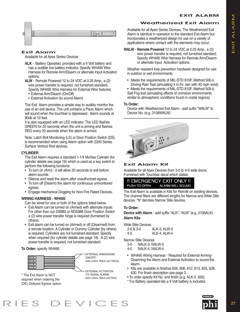
27E R I E S D E V I C E S
EX
IT A
LA
RM
EXIT ALARM
Weatherized Exit Alarm
Available for all Apex Series Devices
ALK - Battery Operated, provided with a 9 Volt battery and has a audible low battery indicator. Specify WH495 Wire Harness for Remote Arm/Disarm or alternate Input Activationoptions.
ALW - Remote Powered 12 to 24 VDC at 0.25 Amp., a (2) wire power transfer is required, not furnished standard. Specify WH495 Wire Harness for External Wire features:• External Arm/Disarm (On/Off)• External Activation (to sound Alarm)
The Exit Alarm provides a simple way to audibly monitor the use of an exit device. The unit contains a Piezo Alarm which will sound when the touchbar is depressed. Alarm sounds at 80db at 10 feet.It is also equipped with an LED indicator. The LED flashes GREEN for 20 seconds when the unit is arming and flashes RED every 20 seconds when the alarm is armed.
Note: Latch Bolt Monitoring (LS) or Door Position Switch (DS) is recommended when using Alarm option with 2200 Series Surface Vertical Rod devices.
CYLINDERThe Exit Alarm requires a standard 1-1/4 Mortise Cylinder (for cylinder details see page 19) which is used as a key switch to perform the following functions:• To turn on (Arm) - it will allow 20 seconds to exit before
alarm sounds.• Silence and reset the alarm after unauthorized egress.• To turn off (Disarm) the alarm for continuous unmonitored
egress.• Engage mechanical Dogging for Non-Fire Rated Devices.
WIRING HARNESS - WH495Can be wired for one or both of the options listed below.• Exit Alarm can be turned on (Armed) with alternate inputs.
For other than our DS880 or NDS986 Door Position Switch a (2) wire power transfer hinge is required (furnished by others).
• Exit alarm can be turned on (Armed) or off (Disarmed) from a remote location. A Cylinder or Dummy Cylinder (by others)is required. Cylinders are not furnished standard. Specify when required (for cylinder details see page 19). A (2) wire power transfer is required, not furnished standard.
To Order: specify WH495
Available for all Apex Series Devices. The Weatherized Exit Alarm is identical in operation to the standard Exit Alarm but incorporates a weatherized design for use on a variety of applications where contact with the elements may occur.
WALW - Remote Powered 12 to 24 VDC at 0.25 Amp., a (2) wire power transfer is required, not furnished standard. Specify WH495 Wire Harness for Remote Arm/Disarm or alternate Input Activation options.
Weather resistant loss prevention hardware designed for use in outdoor or wet environments
• Meets the requirements of MIL-STD 810F, Method 506.4, Driving Rain Test (simulating 4 in./hr. rain with 40 mph wind)
• Meets the requirements of MIL-STD 810F, Method 509.4, Salt Fog test (simulating effects of corrosive environments similar to atmospheric conditions found in costal regions)
To Order:Device with Weatherized Exit Alarm - add suffix “WALW” to Device No. (e.g. 2108WALW)
Exit Alarm Kit
Available for all Apex Devices from 3-0 to 4-0 wide doors.Furnished with Touchbar decal which states:
The Exit Alarm is available in Kits for Retrofit on existing devices.The channel fillers are different lengths for Narrow and Wide Stiledevices. “N” denotes Narrow Stile devices.
To Order:Device with Alarm - add suffix “ALK”, “ALW” (e.g. 2108ALK)Alarm Kits
Wide Stile Devices2-6 & 3-0 ALK-3, ALW-34-0 ALK-4, ALW-4
Narrow Stile Devices3-0 NALK-3, NALW-34-0 NALK-4, NALW-4
• WH495 Wiring Harness - Required for External Arming/Disarming the Alarm and External Activation to sound theAlarm.
• Kits are available in finishes 605, 606, 612, 613, 625, 628, 630. For finish description see page 3.
• To order specify Kit No. and finish (e.g. ALK-3 626). * For Battery operated kits a 9 Volt battery is included.
Exit Alarm
EXTERNAL ARM/DISARM(ON/OFF)(wire colors: Black and Yellow)
EXTERNAL ACTIVATION(TO SIGNAL ALARM)(wire colors: Black and Red)
* The Exit Alarm is NOTrequired when ordering the(DE) Delayed Egress option.

28 A P E X 2 0 0 0 S E R I E S D E V I C E S
ELEC
TR
IC D
EV
ICES ELECTRIC DEVICES
E2103, E2203, E2703 andE2803 Electric Device
Available for 2100, 2200, 2700 and 2800 Series Devices. TheElectric Device controls entry by remote locking or unlocking ofthe outside trim. In addition to a 24 VDC solenoid, the exit deviceis also equipped with a SPDT - single pole double throw switch.The switch monitors the outside trim (locked or unlocked).
The device is furnished standard as Fail Secure (FSE). Whenpower is off the trim is locked. Power is applied to unlock the trim.May be field converted to the Fail Safe (FS) mode. (FS) - power is applied to lock the trim. Specify (FS) or (FSE) mode when ordering. Specify outside Trim with “08” function. The outside keycylinder retracts the latchbolt for mechanical override. If outsidecylinder (mechanical override) is not required, specify outside trimwith “14” function.
E2103K Electric Rim Device Kit To convert 2103, FL2103 devices to E2103, FLE2103 devices inthe field. The Kit includes Trim locking assembly and Electric “E”locking assembly.
Electrical Ratings:Switch rated to 2 Amps at 24VDC SPDTSolenoid current draw: 0.3 Amps.
To Order:Device: specify prefix “E” (e.g. E2103 FSE 4908A)Rim Device Kit: specify Kit No. (e.g. E2103K FSE)
Note: The exit device can be used as a conduit for wiring to the hinge side of the door.
Electric Mortise Lock - HandedThe Mortise lock is available with the following electrical options:MODEL NO. DESCRIPTION
• LSM303, LSM303F - latchbolt monitoring, “03” Function• LSM308, LSM308F - latchbolt and trim locked or
unlocked monitoring, “08” Function• EM303, EM303F - electric lock/unlock with switch to
monitor the outside trim (locked orunlocked)
• LSEM303, - electric lock/unlock with switches LSEM303F to monitor the outside trim (locked
or unlocked) and to monitor the latchbolt.
Electrical Ratings:Switch rated to 2 Amps at 24VDC SPDTSolenoid current draw: 0.2 Amps.
Mortise Lock is furnished standard as Fail Secure (FSE). Whenpower is off the trim is locked. Power is applied to unlock the trim. May be field converted to the Fail Safe (FS) mode. (FS) - power is applied to lock the trim.
To Order: Specify EM303 x (FSE) or (FS) x handing x finish (e.g. EM303 FSE RHRB 630).
E2303 Electric MortiseDevice
The Electric Mortise Device controls entry by remote locking orunlocking of the outside trim. In addition to a 24 VDC solenoid,the mortise lock is also equipped with a SPDT - single pole double throw switch. The switch monitors the outside trim(locked or unlocked).
The device is furnished standard as Fail Secure (FSE). Whenpower is off the trim is locked. Power is applied to unlock thetrim. May be field converted to the Fail Safe (FS) mode. (FS) -power is applied to lock the trim. Specify (FS) or (FSE) modewhen ordering. Specify outside Trim with “08” function. The out-side key cylinder retracts the latchbolt for mechanical override.If outside cylinder (mechanical override) is not required, specifyoutside trim with “14” function.
Field ConversionTo convert 2303, FL2303 devices to E2303, FLE2303 devices in the field a Electric Mortise Lock is required. Specify EM303, EM303F, LSEM303 or LSEM303F (see below for Electric Mortise Locks).
Electrical Ratings:Switch rated to 2 Amps at 24VDC SPDTSolenoid current draw: 0.2 Amps.
To Order:Device: specify prefix “E” (e.g. E2303 FSE M4908A)
1-1/4"
4"
8"
7/8"
4-1/8"2-3/4"
5-3/4"
5/16"
Wiring DiagramLATCHBOLT MONITORINGNORMALLY OPEN /NORMALLY CLOSED SWITCH
LOCK / UNLOCK MONITORINGNORMALLY OPEN /NORMALLY CLOSED SWITCH
BRIDGE RECTIFIER RECF1000OPTIONAL - REQUIRED IFPOWERED BY AC. AVAILABLEIN 24V VERSION.(specify RECF1000 when ordering)

29E R I E S D E V I C E S
MO
NIT
OR
ING
SW
ITC
HESMONITORING SWITCHES
Touchbar Monitoring
Available for all Apex Series Devices. The Touchbar Monitoring Switch is an internally mounted switch that is used to signal electromagnetic locks, horns, monitoring stations or otherelectronic components.
• UL Listed for Panic and Fire for Class II Circuitry.• TS and TDS can be used in combination with all Apex
options including ELR Devices.
TS (SPDT - Single Pole, Double Throw) version allows for interface with one external component. A (2) wire power transferis required, not furnished standard.
TDS (DPDT - Double Pole, Double Throw) version allows for interface with two external components. A (4) wire power transfer is required, not furnished standard.
To Order: specify prefix TS or TDS (e.g. TS2108)
Touchbar Monitoring Conversion Kit
TS and TDS options are available as kits, specify TSK309 for Single Switch Monitoring or TDSK310 for Double Switch Monitoring.
Electrical Ratings:TS: Switch rated to 2 Amps at 24VDC SPDTTDS: Switch rated to 2 Amps at 24VDC DPDT
Latchbolt Monitoring
Available for Wide Stile Rim, Mortise and Vertical Rod Devices.The Latchbolt Monitoring Switch is an internally mounted switchthat monitors the position of the latchbolt. The switch can be used to signal a monitoring station or an alarm such as a Precision ALK/ALW Exit Alarm. For the security of the openinga Door Position Monitoring Switch is recommended.
• UL Listed for Panic and Fire for Class II Circuitry.• LS and LDS can be used in combination with all Apex options
including ELR Devices.LS (SPDT - Single Pole, Double Throw) version allows for inter-
face with one external component. A (2) wire power transfer is required, not furnished standard.
LDS (DPDT - Double Pole, Double Throw) version allows for interface with two external components. A (4) wire power transfer isrequired, not furnished standard.
To Order: specify prefix LS or LDS (e.g. LS2108)
Latchbolt Monitoring Conversion KitLS or LDS option is available as a kit for Wide Stile Devices, specify LSRK298 or LDSRK299 for Rim Devices or LSVK910 for Vertical Rod Devices. For Mortise Devices see Electric Mortise Lock, page 28.
Electrical Ratings:LS: Switch rated to 2 Amps at 24VDC SPDTLDS: Switch rated to 2 Amps at 24VDC DPDTWeatherized
Touchbar Monitoring
Available for all Apex Series Devices. Weatherized Touchbar Switch WTS/WTDS is designed for use on a variety of exit device applications where contact with the elements may occur.Provided with the same specifications as the standard Touchbarmonitoring.
• Meets the requirements of MIL-STD 810F, Method 506.4, Driving Rain Test (simulating 4 in./hr. rain with 40 mph wind)
• Meets the requirements of MIL-STD 810F, Method 509.4, Salt Fog test (simulating effects of corrosive environments similar to atmospheric conditions found in costal regions)
To Order: specify prefix WTS or WTDS (e.g. WTS2108)
Door PositionMonitoring Switch
A Magnetic Reed type switch used to monitor the position of a door from a remote location. It is mounted in the Touchbar Endcap and Door Frame.
To Order: Wide Stile: specify DS880 and finish.
Narrow Stile: specify NDS986 and finish.
Electrical Ratings: 1.5 Amps at 24VDC SPDT
EPT-2 Armored flex conduit.Accepts up to 1/4 diameter wirebundle. Eighteen inches long.
To Order: specify EPT-2.
Power Transfer
EPT-5 Power Transfer with steel housing and flexible tube. Secure and inconspicuouschannel to bring power from the frame to thedoor. Narrow, shallow channel easily mortises into door edges. Accepts up to 5/16" diameter wire bundle. Accommodatesdoors that swing open 120 degrees. Unit is concealed when the door is closed. Suitablefor wood, aluminum or steel applications.
Finish: Bright Chrome. Will hold up to (10) 22 gauge Teflon coated wires.
To Order: specify EPT-5.

30 A P E X 2 0 0 0 S E R I E S D E V I C E S
STR
IKES STRIKES
Rim Exit DevicesFor Minimum Stile Widths see pages 32 and 33.
Vertical Rod Exit DevicesTop Strike - For Surface Vertical Rod Devices, S300standard and S301 optional, see above.
2100 Rim xVertical Rod ExitDevice
1-1/8"1/2"
2-7/8"
1-3/4"1/2"
2"
S458 OptionalFor Rim Devices. Black Powder Coated Investment Cast, Stainless Steel Base and Roller.
S988 StandardFor Narrow Stile Rim Devices. Black Powder Coated Investment Cast, Stainless Steel Base and Roller. Includes Rub Strip.
S300 StandardFor Rim and Top Strike for SVR Devices. Specify for FL2400 Devices on Pair of Doors with Mullion. Black Powder Coated InvestmentCast Stainless Steel.
1-1/8"3/4"
2-7/8"
1-1/8"3/4"
2-7/8"
S301 OptionalFor Rim and Top Strike for SVR Devices. Black PowderCoated Investment Cast, Stainless Steel Base and Roller.
S460 Bottom StrikeFor Vertical Rod Devices,Surface or Concealed.Black Powder Coated Steel.
S519 Top StrikeFor Concealed Vertical Rod Devices.Black Powder Coated InvestmentCast Stainless Steel.
1-5/8"1/8"
2-3/8"
1-1/4"11/16"
1-19/32"
Mortise Exit DevicesOpen Back Strikes allow a pair of doors to open and close independently. Strikes are handed. Specify Hand same as Mortise Lock (e.g. RHRB).
S982 StandardCurved lip.
S983 Optional7/8" Flat Lip to center. For overlapping astragal.
1-1/4" 3/32"
4-7/8"
1-1/4" 3/32"
4-7/8"
S984 OptionalOpen Back StrikeFor 4-7/8" x 1-1/4" door edge cutout.
1-1/4" 3/32"
4-7/8"
S985 OptionalOpen Back StrikeFor 8" x 1-1/4" door edgecutout.
1-1/4" 3/4"
8"
S459 Optional Rim StrikeFor Non Fire Rated 2100 Rim x Vertical Rod Device on a Pair of Doors without aMullion. Black Powder Coated Investment Cast Stainless Steel.
2"5/8"
2-3/8"
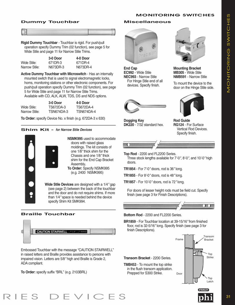
31E R I E S D E V I C E S
MO
NIT
OR
ING
SW
ITC
HESMONITORING SWITCHES
Dummy Touchbar
Shim Kit - for Narrow Stile Devices
Rigid Dummy Touchbar - Touchbar is rigid. For push/pull operation specify Dummy Trim (02 function), see page 5 for Wide Stile and page 11 for Narrow Stile Trims.
3-0 Door 4-0 DoorWide Stile: 671DR-3 671DR-4Narrow Stile: N673DR-3 N673DR-4
Active Dummy Touchbar with Microswitch - Has an internally mounted switch that is used to signal electromagnetic locks, horns, monitoring stations or other electronic components. For push/pull operation specify Dummy Trim (02 function), see page5 for Wide Stile and page 11 for Narrow Stile Trims.Available with CD, ALK, ALW, TDS, DS and NDS options.
3-0 Door 4-0 DoorWide Stile: TS672DA-3 TS672DA-4Narrow Stile: TSN674DA-3 TSN674DA-4
To Order: specify Device No. x finish (e.g. 672DA-3 x 630)
Embossed Touchbar with the message “CAUTION STAIRWELL”in raised letters and Braille provides assistance to persons withimpaired vision. Letters are 5/8" high and Braille is Grade 2, ADA compliant.
To Order: specify suffix “BRL” (e.g. 2103BRL)
Miscellaneous
End CapEC992 - Wide StileNEC993 - Narrow Stile
For Hinge Stile end of all devices. Specify finish.
Mounting BracketMB305 - Wide StileNMB591 - Narrow Stile
To mount the device to thedoor on the Hinge Stile side.
Dogging KeyDK220 - 7/32 standard hex.
Top Rod - 2200 and FL2200 Series.Three stock lengths available for 7'-0", 8'-0", and 10'-0" high doors.
TR1854 - For 7'-0" doors, rod is 36" long.
TR1855 - For 8'-0" doors, rod is 48" long.
TR1857 - For 10'-0" doors, rod is 72" long.
For doors of lesser height rods must be field cut. Specify finish (see page 3 for Finish Descriptions).
Bottom Rod - 2200 and FL2200 Series.
BR1859 - For Touchbar location at 39-15/16" from finished floor, rod is 32-5/16" long. Specify finish (see page 3 for finish Descriptions).
Transom Bracket - 2200 Series.
TMB453 - To mount the top strikein the flush transom application. Prepped for S300 Strike.
Rod GuideRG124 - For Surface
Vertical Rod Devices. Specify finish.
Braille Touchbar
NSMK995 used to accommodatedoors with raised glass moldings. The kit consists of one 1/8" thick shim for the Chassis and one 1/8" thick shim for the End Cap Bracket Assembly.
To Order: Specify NSMK995 (e.g. 2400 NSMK995)
Wide Stile Devices are designed with a 1/4" gap(see page 2) between the back of the touchbarand the door and do not require shims. If more than 1/4" space is needed behind the device specify Shim Kit SMK994.
Frame
TopStrike
TopLatch
TransomBracket
Door

32 A P E X 2 0 0 0 S E R I E S D E V I C E S
MIN
IMU
M STIL
E W
IDTH
- A
pe
x W
ide
Stile MINIMUM STILE WIDTH
Single Doors
Pair of Doors
Backset 2-3/4"
2-1/4"
Stile Width4-1/4" Min.
Strike
Rim Device withS300 or S301 Strikes
Backset 3-1/8"
2-1/4" 2-1/4"2"
Stile Width4-5/8" Min.
Backset 3-1/8"
Stile Width4-5/8" Min.
Strike Strike
Mullion
Rim Devices with S300 or S301Strikes and Mullion
Backset 3-1/8"
2-1/4" 2-1/4"2"
Stile Width4-5/8" Min.
Backset 3-1/8"
Stile Width4-5/8" Min.
Strike Strike
Mullion
Rim Devices with S458Strikes and Mullion
Backset 2-3/4"
Stile Width4-1/4" Min.
Backset 2-1/4"
Stile Width4-1/4" Min.
Strike
Rim Device and Vertical RodDevice with S459 Strike
Backset 1-3/4"
Stile Width3-1/2" Min.
Backset 1-3/4"
Stile Width3-1/2" Min.
Two Vertical Rod DevicesSurface or Concealed
For 3-1/2" medium stile doors consult factory.
Backset 2-3/4"
Stile Width4-1/4" Min.
Backset 2-1/4"
Stile Width4-1/4" Min.
Mortise and Vertical Rod Device Surface or Concealed
1-1/4"
2-1/2" 2-1/2"
Stile Width4" Min.
Stile Width4" Min.
1-1/4"
Wood Door ConcealedVertical Rod Devices
Rim Device with S988 StrikesFor 3-1/2" medium stile Aluminumdoors and frames. Consult factory.
Mortise DeviceStrike
Backset1-15/16"
2-1/16"
Stile Width3-1/2" Min.
Backset 2-3/4"
Stile Width4-1/4" Min.
DeviceBackset
LatchBackset
LatchBackset
DeviceBackset

33E R I E S D E V I C E S
MIN
IMU
M STIL
E W
IDTH
- A
pe
x 2000 N
arr
ow
StileMINIMUM STILE WIDTH
Single Doors – Rim Devices
Pair of Doors, Rim Devices
Backset 1-1/16"
1-3/16"
Minumum StileWidth 1-3/4"
Strike
Rim Device with S988 Strike
Backset 2-1/16"
1-3/16" 2"
3" Minumum Stile
Backset 2-1/16"
3" Minumum Stile
Strike1-3/16"
Strike
Rim Devices with S458Strikes and Mullion
Backset 2-5/16"
1-7/16" 2"
3-1/4" Minumum Stile
Backset 2-5/16"
3-1/4" Minumum Stile
Strike1-7/16"
Strike
Rim Devices with S300 or S301Strikes and Mullion
Rim Device with S458 Strike. Rim Device with S300or S301 Strikes
Strike
Backset 1-11/16"
1-3/16"
2-5/8" Minimum Stile
Strike
Backset 1-15/16"
1-7/16"
2-7/8" Minimum Stile
Concealed Vertical Rod Devices
Backset 1-1/16"
1-3/16"
Minumum StileWidth 1-3/4"
Single Door Pair of Doors
Backset 1-1/16"
1-3/4" Minumum Stile
Backset 1-1/16"
1-3/4" Minumum Stile
Device Dimensions
2-3/16"
2-1/8"
3-1/2" TouchbarNeutral
2-5/8" TouchbarDepressed
Wide Stile Devices Narrow Stile Devices
2-11/16"
2-3/16"
2-1/8"
3-1/4" TouchbarNeutral
2-3/8" TouchbarDepressed
1-1/4"
Two Concealed VerticalRod Devices

34 A P E X 2 0 0 0 S E R I E S D E V I C E S
TR
IM D
IMEN
SIO
NS TRIM DIMENSIONS
1700A
2-3/4"
15"
2-1/8"
6"
1700B
2-3/4"
15"
2-3/8"
6"
1700C
2-3/4"
15"
2-1/2"
6"
2000C
1-3/4"
15"
C03
3/8"
2-1/2"
2-1/2"
2-7/16"
6"
4900A
2-7/8"
4900B 4900C 4900D 4900K
9-11/16"
4-7/8"
7/16"2-3/4"
2-7/8"
9-11/16"
4-1/2"
2-3/4"
2-1/16"
2-7/8"
9-11/16"
4-7/8"
3-1/2"7/16"
2-7/8"
9-11/16"
4-5/8"
2-7/8"
7/16"
2900A
1-3/4"
7-3/4"
4-5/8"
7/16"
2-3/8"
2900B
1-3/4"
7-3/4"
4-1/2"
1-3/8"
2-3/4"
2900C
1-3/4"
7-3/4"
4-7/8"
7/16"
3-1/4"
2900D
1-3/4"
7-3/4"
4-5/8"
7/16"
2-5/8"
2-7/8"
9-11/16"
4-1/8"
2-1/8"
Lever Centerline 38-3/16" from Finish Floor when Device Centerline is 39-15/16".
Lever Centerline 38-3/16" from Finish Floor when Device Centerline is 39-15/16".
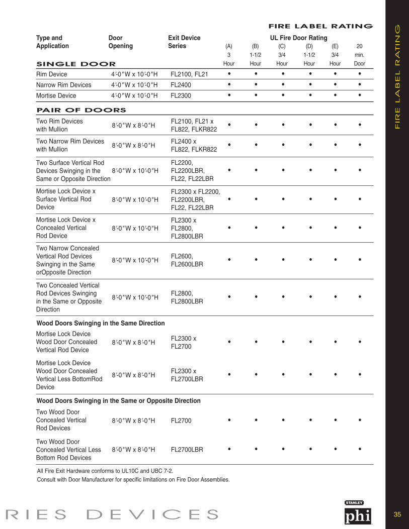
35E R I E S D E V I C E S
FIR
E LA
BEL R
ATIN
G
FIRE LABEL RATING
SINGLE DOOR
Type and Door Exit Device UL Fire Door RatingApplication Opening Series
Rim Device 4'-0" W x 10'-0" H FL2100, FL21 • • • • • •Narrow Rim Devices 4'-0" W x 10'-0" H FL2400 • • • • • •Mortise Device 4'-0" W x 10'-0" H FL2300 • • • • • •
(A) (B) (C) (D) (E) 20
3 1-1/2 3/4 1-1/2 3/4 min.
Hour Hour Hour Hour Hour Door
PAIR OF DOORS
Two Rim Devices with Mullion
8'-0" W x 8'-0" HFL2100, FL21 xFL822, FLKR822
• • • • • •
Two Narrow Rim Devices with Mullion
8'-0" W x 8'-0" HFL2400 xFL822, FLKR822
• • • • • •
Two Surface Vertical RodDevices Swinging in theSame or Opposite Direction
8'-0" W x 10'-0" HFL2200,FL2200LBR,FL22, FL22LBR
• • • • • •
Mortise Lock Device xSurface Vertical RodDevice
8'-0" W x 10'-0" HFL2300 x FL2200,FL2200LBR,FL22, FL22LBR
• • • • • •
Mortise Lock Device xConcealed VerticalRod Device
8'-0" W x 10'-0" HFL2300 xFL2800,FL2800LBR
• • • • • •
Mortise Lock Device Wood Door ConcealedVertical Rod Device
8'-0" W x 8'-0" HFL2300 xFL2700
• • • • • •
Mortise Lock Device Wood Door ConcealedVertical Less BottomRodDevice
8'-0" W x 8'-0" HFL2300 xFL2700LBR
• • • • • •
Two Narrow ConcealedVertical Rod DevicesSwinging in the SameorOpposite Direction
8'-0" W x 10'-0" HFL2600,FL2600LBR
• • • • • •
Two Concealed VerticalRod Devices Swingingin the Same or OppositeDirection
8'-0" W x 10'-0" HFL2800,FL2800LBR
• • • • • •
Wood Doors Swinging in the Same Direction
Two Wood DoorConcealed VerticalRod Devices
8'-0" W x 8'-0" H FL2700 • • • • • •
Two Wood DoorConcealed Vertical LessBottom Rod Devices
8'-0" W x 8'-0" H FL2700LBR • • • • • •
Wood Doors Swinging in the Same or Opposite Direction
All Fire Exit Hardware conforms to UL10C and UBC 7-2.
Consult with Door Manufacturer for specific limitations on Fire Door Assemblies.

PR
EC
ISIO
N H
AR
DW
AR
E
For more information on Stanley Security Solutions’ products, services, and office locations visit our web site at www.stanleysecuritysolutions.com
Stanley Security Solutions, Inc.6161 E. 75th Street Indianapolis, Indiana 46250
www.stanleysecuritysolutions.com© 2007 Stanley Security Solutions, Inc. and Stanley Logistics
Product information contained in this catalog has been compiled and presented with as much care and completeness as is reasonably possible. Errorsor mistakes may be present, and in many cases, reliance has been placed on information supplied by other manufacturers which may be in error orwhich may be subject to changes or modifications by the manufacturer without notice and without obligation. Therefore, no guarantee can be made orshould be assumed or implied with regards to product information contained in this catalog.
7.5M R807FPPHI005