area monitor operation manual revision 2
TRANSCRIPT

1
INTERNATIONAL
®S.E. International, Inc. P.O. Box 39, 436 Farm Rd. Summertown, TN 38483 USA
1.800.293.5759 | 1.931.964.3561 | Fax: 1.931.964.3564www.seintl.com | [email protected]
OPERATION MANUAL
Area Monitor

2
Chapter 13: Unit Conversions 20Radiation Measurement Units 20Converting CPS to mR/h 20Appendix A: Technical Specifications 21Appendix B: Limited Warranty 22Appendix C: Relays and Triggers Technical Info 23DB-9 Relay Connector 23Appendix D: How to Send a Text Message Via Email 23Calibration Database Application 24
ContentsChapter 1: Introduction 3Precautions 3Chapter 2: Quick Start 4Chapter 3: General Operation Using The Monitor 5The General Operation Screens 5The Main Screen 5The System Info Screen 5Display of Alarms 5Chapter 4: Selecting Base Units of Measurement 6The Set Base Unit Screen 6Chapter 5: Setting The Alarm Levels On The Monitor 7The Set Alarm Levels Screen 7The Set Alarm Indicators Screen 7Chapter 6: Connecting Relays and Triggers 8DB-9 Relay Connector 8Connecting A Remote Alarm 8Chapter 7: Installing The Area Monitor PC Software 9Installing the Area Monitor Server PC Software 9Com Port Selection and Connection 9Chapter 8: Ethernet Configuration 9The Set Communications Screen 9Chapter 9: Area Monitor Server Software 10File Menu 10Exit 10View Menu 10Floor Plan 10Server IP Address 10Communication Lost - Hide Unconnected 10Calibration and Settings Screen 11Chapter 10: Sending Alerts 12How to Send Alerts Via Email and Text Message 12Software Alert Rules 12Setting Up To Send An Alert 12Hardware Alert Settings 13Setting Up To Send An Alert 13Chapter 11: Help And View Detail 14Open Help File 14About RSA Area Monitor Server Software 14View Detail Screen 14Exporting Data 14Loading a Floor Plan 14Deleting Units from the Area Monitor Server Software Permanently 15Acknowledging Alarms and Warnings 15Monitor Failure Detected 15Radiation Warning (Low Alarm on the Touch Screen) 16Critical Radiation Alert (High Alarm on the Touch Screen) 16Lost Communication 16Chapter 12: Calibration Settings Using The Monitor 17The Area Monitor Calibration Screens 17Accessing The Calibration Settings Screen 17The Set High Voltage Screen 17The Set Threshold Screen 18The Set Dead Time Screen 18The Set Cal Constant Screen 19The Set Calibration Date Screen 19Setup and Calibration Sequence 19

3
The Radiation Alert® Area Monitor is one of the most user friendly, all inclusive, state-of-the-art radiation area monitors available. The easy to use interface is an intelligent resistive touch screen display featuring a large 5-digit LED readout.It comes with either an internal or external detector and free software for monitoring every Radiation Alert® Area Monitor on your network. Includes user selectable warning indicators for low and high radiation alarm levels, low battery, and detector failure. All the settings are stored internally, even when power is disconnected.
PrecautionsTo keep the Area Monitor in good condition, handle it with care, and observe the following precautions:
• CAUTION: Never touch the Area Monitor or the external detector to a surface that may be contaminated. You may contaminate the instrument.
• Do not get the Area Monitor wet. Water can damage the circuitry.• The Area Monitor is designed for indoor use.• This instrument may be sensitive to and may not operate properly in radio
frequency, microwave, electrostatic, and high electromagnetic fields.• In the event of exposure to high static discharge, which may result in the screen
going blank, please restart the unit to resume normal function.• Do Not connect or disconnect an external probe to the base unit while the Area Monitor is powered on.
Chapter 1: Introduction

4
Chapter 2: Quick Start
1. If you are using an external detector, ensure that the unit is powered off before connecting the detector to the Area Monitor with the included C to C cable. (If your Area Monitor has an internal detector, skip this step and proceed to step 2.) NOTE: The Maximum Cable Lengths for GM Probes is 100 ft. and for Scintillation Probes is 50 ft.
2. Plug the included +12VDC power supply into the right side of the Area Monitor, located below the power switch. Then plug the power supply into an electrical outlet.
3. Once you have connected the probe and power, turn the Power switch ON. The power switch is located on the right side of the Area Monitor near the power input.
4. The Area Monitor will quickly go to the start up screen while the system boots up. It will take approximately 30 seconds to finish the boot process.
5. After the boot process has been completed, the main screen will be displayed and the Area Monitor is now operational. The display will update to show the current radiation rate within a few seconds.
7. To acknowledge and/or silence any alarm, tap the ALARM button that appears towards the lower center of the screen when an alarm has been triggered.
If the Area Monitor is connected to a remote alarm, see Chapter 6.
6. To see details of the system set up, tap the System… button on the touch-screen display.

5
The General Operation ScreensThe Radiation Alert® Area Monitor has two separate screens for general operation of the unit; the Main Screen and the System Info screen.
The Main ScreenThe Main Screen is divided into two general sections. The top two thirds displays the current radiation rate. The lower section displays the units used, voltages of both the external power and the internal battery, and the System… button. This area is also used to display alarm information and provide a button to acknowledge and/or silence current alarms.
The System Info ScreenPressing the System... button will open the System Info screen.
This screen displays several key system parameters. They cannot be edited from this screen. The upper right corner displays the current radiation rate. All alarms are still active and function normally while this screen is displayed. Press the Back… button to return to the main screen.
Display of AlarmsThere are three alarm types:
Hardware Fail Low HighSoftware Fail Radiation
WarningCritical Radiation Alert
The FAIL Alarm condition occurs when the incoming count rate is lower than the entered set point, which is normally set to some fraction of the ambient background. The FAIL Alarm can also indicate the Area Monitor is not functioning properly (e.g. the high voltage has failed, the detector has failed or has been disconnected).
To acknowledge and/or silence any alarm, tap the ALARM button that appears towards the lower center of the screen. The type of alarm is still indicated (Low, High, Fail) on the display, but the horn and light both stop. If the Area Monitor is connected to a remote alarm, see Chapter 6.
NOTE: Unless otherwise requested, BASE units are set to:
CPM: High Alarm 3000, Low Alarm 1000, Fail Alarm 1.0
Chapter 3: General Operation Using The Monitor

6
Chapter 4: Selecting Base Units of MeasurementThe Set Base Unit ScreenTo enter the Set Base Unit screen, use the included pin, a paper clip, or another small object to press the recessed button on the bottom of the Area Monitor. This will cause the Enter Passkey screen to display. (The default is 1234.) Enter your passkey and select the Set button. NOTE: The passkey can only be changed using the software, with the Area Monitor connected to a PC through the USB or Ethernet ports.
From the Calibration Settings screen, tap the Base Unit… button to open the Set Base Unit screen. The Base Unit sets the units of measurement that will be used for the Area Monitor display and the alarm set points.
Tap the radio button next to the desired Base Unit, and the displayed rate will immediately be converted to that unit. When finished, tap the Back… button to return to the Calibration Settings screen.
The Base Unit also determines what MINIMUM subunit will be displayed. For example, if the base unit is mR/h and the radiation field on the detector is 80 µR/h, the displayed value will be 0.1 mR/h.
7
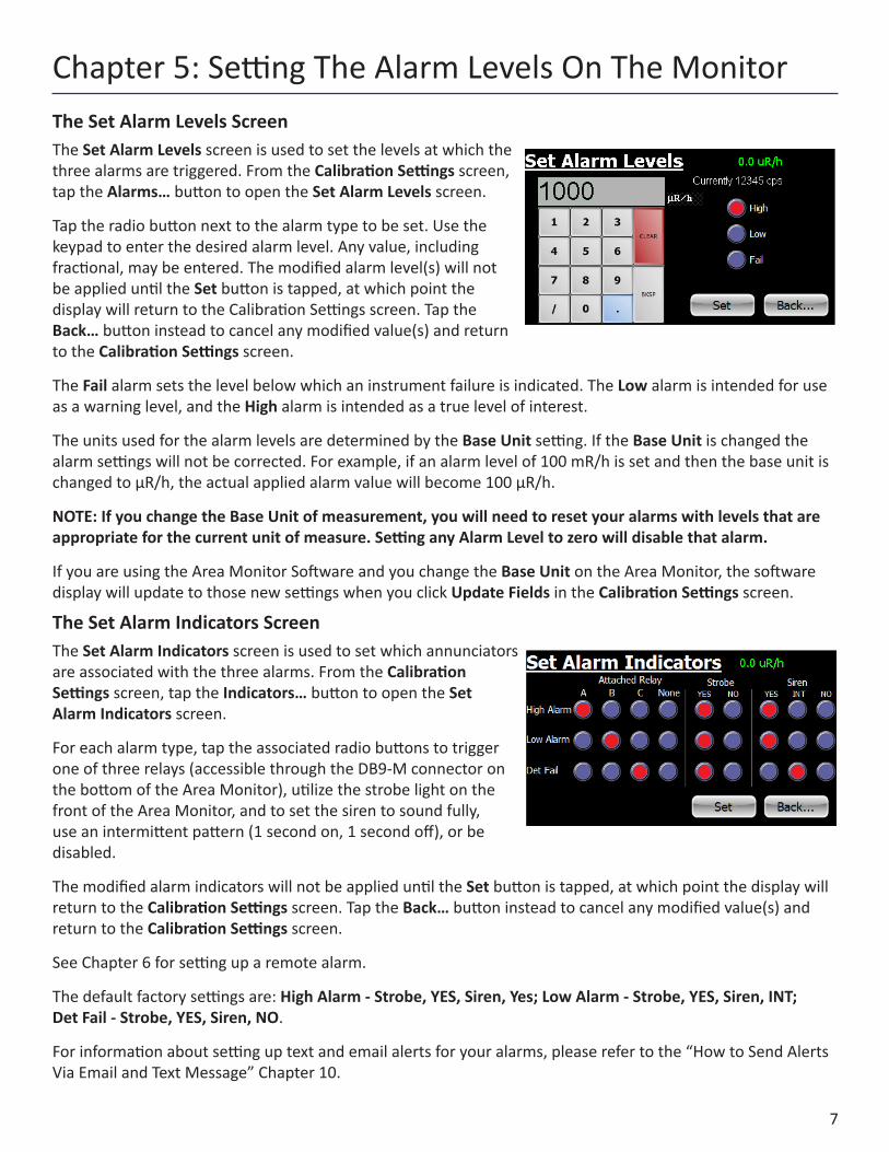
Chapter 5: Setting The Alarm Levels On The MonitorThe Set Alarm Levels ScreenThe Set Alarm Levels screen is used to set the levels at which the three alarms are triggered. From the Calibration Settings screen, tap the Alarms… button to open the Set Alarm Levels screen.
Tap the radio button next to the alarm type to be set. Use the keypad to enter the desired alarm level. Any value, including fractional, may be entered. The modified alarm level(s) will not be applied until the Set button is tapped, at which point the display will return to the Calibration Settings screen. Tap the Back… button instead to cancel any modified value(s) and return to the Calibration Settings screen.
The Fail alarm sets the level below which an instrument failure is indicated. The Low alarm is intended for use as a warning level, and the High alarm is intended as a true level of interest.
The units used for the alarm levels are determined by the Base Unit setting. If the Base Unit is changed the alarm settings will not be corrected. For example, if an alarm level of 100 mR/h is set and then the base unit is changed to µR/h, the actual applied alarm value will become 100 µR/h.
NOTE: If you change the Base Unit of measurement, you will need to reset your alarms with levels that are appropriate for the current unit of measure. Setting any Alarm Level to zero will disable that alarm.
If you are using the Area Monitor Software and you change the Base Unit on the Area Monitor, the software display will update to those new settings when you click Update Fields in the Calibration Settings screen.
The Set Alarm Indicators ScreenThe Set Alarm Indicators screen is used to set which annunciators are associated with the three alarms. From the Calibration Settings screen, tap the Indicators… button to open the Set Alarm Indicators screen.
For each alarm type, tap the associated radio buttons to trigger one of three relays (accessible through the DB9-M connector on the bottom of the Area Monitor), utilize the strobe light on the front of the Area Monitor, and to set the siren to sound fully, use an intermittent pattern (1 second on, 1 second off), or be disabled.
The modified alarm indicators will not be applied until the Set button is tapped, at which point the display will return to the Calibration Settings screen. Tap the Back… button instead to cancel any modified value(s) and return to the Calibration Settings screen.
See Chapter 6 for setting up a remote alarm.
The default factory settings are: High Alarm - Strobe, YES, Siren, Yes; Low Alarm - Strobe, YES, Siren, INT; Det Fail - Strobe, YES, Siren, NO.
For information about setting up text and email alerts for your alarms, please refer to the “How to Send Alerts Via Email and Text Message” Chapter 10.

8
DB-9 Relay Connector The Radiation Alert Area Monitor can interface with external triggers and external strobes/horns via the DB-9 relay connector, located on the bottom of the unit. See “Appendix C: Relay and Triggers Technical Info” for more information.
Connecting A Remote AlarmTo connect a remote alarm with a standard serial cable, plug the female end of the cable into the bottom of the area monitor and the male end into the bottom of the remote alarm. Once the unit is connected, you can set alarm response settings in the Set Alarm Indicators screen. NOTE: All alarm indicators can be modified directly on the Area Monitor or via the Area Monitor PC software.
The strobe and siren settings only apply to the base unit. Regardless of the Set Alarm Indicators on the Base unit, the Remote Alarm settings will be:
• High Alarm - Constant audio alarm, flashing light• Low Alarm - Intermittent audio alarm, flashing light• Fail Alarm - Intermittent audio alarm, flashing light
The alarm and light will continue until the unit is below the set threshold. The alarm and light will continue until the readings are below the set threshold even if the alarm is acknowledged on the Base unit.
Assigning any alarm to relay A will cause the audible alarm to sound and the strobe light to flash, without pause when triggered in the remote alarm. Relay A is generally intended for the high alarm.
Relay B will cause the audible alarm to cycle on and off for about one second each when triggered in the remote alarm. The strobe will flash continuously. Relay B is generally intended for the low alarm.
Relay C will cause the audible alarm to make a short blip about once per second when triggered in the remote alarm. The strobe will flash continuously. Relay C is generally intended for the Det Fail alarm.
Chapter 6: Connecting Relays and Triggers

9
Chapter 8: Ethernet ConfigurationThe Set Communications ScreenIn addition to the touch screen interface, the Area Monitor can communicate with a PC using USB and/or Ethernet and the included Area Monitor PC Software. From the Calibration Settings screen, tap the Comms… button to open the Set Communications screen.
Tap the appropriate radio button to enable the Ethernet and or Serial (USB) functionality. For Ethernet, the IP address of the PC to which data will be sent must be specified on this screen. The modified communications settings will not be applied until the Set button is tapped, at which point the display will return to the Calibration Settings screen. Tap the Back… button instead to cancel any modified value(s) and return to the Calibration Settings screen.
The Area Monitor Server Software enables users to remotely monitor and configure the Radiation Alert Area Monitor via USB or Ethernet, view the area monitors in real time, export collected data, and change the settings of the unit.
Installing the Area Monitor Server PC SoftwareThere is no additional charge for the Area Monitor Server Software. It can be downloaded at seintl.com/area_monitor_software. Once you have downloaded the installer to the PC you would like to install the software on, double click the exe file to begin your software installation. Follow the on-screen prompts until the installation is complete.
Com Port Selection and ConnectionOpen the software and select the com port from the drop down list on the right and click Connect.
If you do not see the correct port displayed, click Refresh Port List.
If your computer is connected by USB and you do not see the active port in the list, unplug and then reconnect the USB cable.
Chapter 7: Installing The Area Monitor PC Software
Note:
1: When using the Ethernet connection the communication is required to pass through either the router or a network switch. The PC is required to be connected to a router or a switch on the same network as the Area Monitor. Incidentally, this means that the PC can use WiFi as long as the Area Monitor is wired to a network that also uses WiFi.
2: The “Connect” button on the top right corner of the main Area Monitor screen is only used when connected via USB. The same holds true for the list of Com Ports. The Com Ports are non-functional when using an ethernet connection. Attempting use of the Com Ports may cuase interference with the ethernet connection.

10
Chapter 9: Area Monitor Server SoftwareFile MenuExitTo exit the software, click EXIT in the File Menu.
View MenuFloor PlanTo load an image of your floor plan, go to View > Floor Plan to open the Floor Plan window. From here, you can place the area monitors listed in the main window of the Area Monitor Server Software on a customized map you can load into the software. Accepted file formats for floor plan images are jpg (jpeg), png, bmp, and tiff files.
Server IP AddressShows the IP address for the computer with the Area Monitor Server Software installed.
Communication Lost - Hide UnconnectedAfter a unit fails on the network, or the network connection to the unit fails, it take approximately 5-10 seconds for the area monitor software to register the lost connection.
If you change the serial number of the area monitor connected to the software, the Area Monitor Server will lose the connection to the previous serial number of the area monitor and create a new area monitor in the software window. If you changed the serial number of the area monitor, the previous settings will appear as an area monitor that has a lost connection. To remove the one listed with the older settings, go to View > Hide Unconnected.

11
Calibration and Settings ScreenThe Calibration and Settings screen is used to change the High Voltage, Threshold, Dead Time, Cal Constant, Server IP Address, Alarms, Serial Number, Detector Serial Number, Detector Description, Cal Date, Base Unit, Communications, and Hardware Alert Settings.
You can access the Calibration and Settings Screen two ways. From the main window select the row in which the area monitor is listed. An arrow to the left side of the row will indicate you have selected the correct unit.
1. Select View > Calibration and Settings2. Right Click on the row and then click
on Calibration and Settings.
After changing any of the settings, you must click on Set, and Enter area monitor password. (The default is 1234.) If you leave the Calibration Settings screen and go back to make more changes, you will have to renter the password.
NOTE: Be sure to set your unit of measurement before setting the alarm levels. When changing units of measurement, if you have already set the alarm levels, the same numeric value will be assigned to the new unit of measurement. For example, if the alarm level is set at 300 CPM (Counts Per Minute) and the units of measurement are changed to mR/h, the alarm setting will change to 300 mR/h. The numeric value stays the same, but the unit of measurement changes.
NOTE: If you change the unit of measurement, you will need to reset your alarms with the correct value for the current unit of measurement.

12
How to Send Alerts Via Email and Text MessageThe Radiation Alert® Area Monitor has the ability to send alert messages via text or email in the event an alert is triggered. There are two different forms of alert settings.
The Software Alert requires the software to be running on the computer connected to the Area Monitor. The Area Monitor must be connected to the network and have access to the internet.
The Hardware Alert settings send the Area Monitor Alerts choices directly to the Area Monitor. Those alert settings are stored on the Area Monitor. Those alerts do not require the software to be running at the time of the alert. The Area Monitor must be connected to the network and have access to the internet.
In the event that an area monitor has lost connection with the network and/or the area monitor server for a period of 10 seconds, Lost Connection will appear in the Area Monitor Server screen under Status. If connection to the network or internet is lost during an alarm event, no emails or text will be sent.
Software Alert RulesTo set the Software Alert Rules, in the main window of the Area Monitor Server Software, click on the View menu and select Software Alert Rules. This will open the Alert Rules window. The Alert Rules window allows the user to set up different responses to different alert levels and direct the notification to the appropriate person. By default, the first Rule name: is titled Unamed Rule. You can change the Rule name to whatever you would prefer.
Setting Up To Send An Alert1. The When monitors: field will list all of the area monitors
connected to the server software. Select the area monitors that you would like to set up to send alerts.
2. Select the alert warnings for which you would like to receive alerts under change status to:.
3. Enter the email address(es) you would like to receive the notifications. If you would like to send a text instead of an email, use an SMS to email gateway. (See Appendix D for more information on SMS to email gateways.)
4. By default, the Area Monitor Server Software uses the S.E. International mail servers to send an alert from [email protected].
5. If you would like to configure the alerts to use your own email server, click Configure Alert Sender and enter the appropriate settings for your email server.
NOTE: Communication Lost sends an alert only when the PC has lost its connection to the Area Monitor. The PC must still be connected to the internet.
Chapter 10: Sending Alerts

13
Hardware Alert SettingsTo set the Hardware Alerts, in the main window of the Area Monitor Server Software, click on the View menu and select Calibration and Settings. Choose the area monitor you wish to modify in the Select Area Monitor SN field. Click on Update Fields to retrieve the current data. From the Calibration and Settings window, click the Hardware Alert Settings. Enter the area monitor password. This will open the Area Monitor Alerts window.
The hardware Area Monitor Alerts enable you to configure a single set of alerts that will be sent via the area monitor. The Hardware Alerts are stored on the area monitor and do not require the Area Monitor Server Software be running to send them. The Area Monitor must be plugged into a network and be provided with internet access.
Setting Up To Send An Alert1. Select the alert warnings for which you would like to receive alerts under When monitor
changes status to: by clicking the corresponding check box.2. In the Send emails to: text box, enter the email address(es) you
would like to receive the notifications. If you would like to send a text instead of an email, use an SMS to email gateway. (See Appendix D for more information on SMS to email gateways.)
3. By default, the Area Monitor Server Software uses the S.E. International mail servers to send an alert from [email protected]. If you would like to configure the alerts to use your own email server, click Configure Alert Sender and enter the appropriate settings for your email server.
4. When you are finished with your settings click OK.

14
Open Help FileOpens a searchable help file for answering basic questions about the use of the software.
About RSA Area Monitor Server SoftwareOpens a window that shows the version number of the software, technical support contact, and the location of the files on your computer that are created when each new area monitor is added or changed in the software.
View Detail ScreenThe View Detail screen displays a histogram of the collected data, the current count rate, the status of the connection, the serial number, and the IP address of the unit. It is also used as a means of collecting data, setting the data logging frequency, and exporting the data received from the area monitor to a text file. You can select how frequently to log the data in the Data Options menu, located in the lower right corner of the View Detail screen.
Exporting DataYou can select the last hour, the last day, the last week, or the last month to export, as well as custom date ranges to export. Export Data is located at the bottom of the Detail For: screen just below the data options. Data is only collected and stored on the computer while connected to an active Area Monitor. If the computer is off or has lost connection for any reason, or the software is not running,` no data will be available from those times.
Loading a Floor PlanTo load an image of your floor plan into the Area Monitor Server Software, open View > Floor Plan to open the floor plan window.
Click the Load Floor Plan Image button, select the image of your floor plan, and click Open.
You will now see your floor plan image in the Floor Plan window. There will also be green square icons (connected area monitors) or purple square icons (lost connection) that represent each monitor on the network. To drag them to the proper position on the floor plan map, scroll over the small box in the upper left corner of each icon and hold down the mouse button to drag them to the desired position on the floor plan map. Once you have placed them where you want them on the floor plan, check the Lock Monitor Locations check box in the upper left of the Floor Plan window. This will ensure that the locations of the area monitors on the floor plan map will not be moved accidentally.
Chapter 11: Help And View Detail

15
Deleting Units from the Area Monitor Server Software PermanentlyIn order to permanently delete any old area monitors in the Area Monitor Server window, you will need to delete the configuration files created by the software on your computer. To do this, go to the Help menu and click About Area Monitor Server. This screen will contain the location of the folder on your computer where all of the configuration files are stored. Click on the address located at the bottom of the screen titled User data location:. This will open the folder and you will see the various folders created by the Area Monitor Server software for each monitor on your network.
Delete any of the folders you want to permanently remove from the area monitor list, along with the ProgramState file. Empty the recycle bin and restart the Area Monitor Server software.
Acknowledging Alarms and WarningsIn the event that an area monitor alarm or warning is triggered, the corresponding row in the main screen will show the state of the event in the status column. When the status of an alarm becomes active, the user can acknowledge the alarm by clicking the Acknowledge button to the right of the alarm status.
Once you have acknowledged an alarm from the Area Monitor Server Software screen, the area monitor horn and strobe will stop at the unit location and the button state will change to (Acknowledged) in the software. If the rate drops below the alarm level, then the alarm will reset and the strobe will stop. This means that if the alarm is triggered and acknowledged and the alarm goes off again, the rate has dipped below the alarm threshold and has risen above the alarm level again. In other words, the rate is hovering around the set alarm level.
The Status has five different states; OK, Monitor Failure, Radiation warning, Critical Radiation Alert, and Communication Lost.
Monitor Failure DetectedIn the event that the area monitor reaches the threshold set for the monitor failure, the Monitor Failure alarm will appear in the status column of the software.
Radiation Warning prior to Acknowledge button click
Radiation Warning after Acknowledge button click

16
Radiation Warning (Low Alarm on the Touch Screen)The Radiation Warning is the low alarm threshold. When the rate gets above the set Radiation Warning, the unit will respond with the settings used in the Set Alarm screen.
Critical Radiation Alert (High Alarm on the Touch Screen)The Critical Radiation Warning is the high alarm threshold. When the rate gets above the set High Alarm, the unit will respond with the settings used in the Set Alarm screen.
Lost CommunicationIn the event that the area monitor has lost connection with the network and/or the area monitor server for a period of 10 seconds, Lost Connection will appear in the status window.
17
The Area Monitor Calibration ScreensThe Radiation Alert® Area Monitor has five separate screens for calibration of the detector in use with the unit. Each of these can be accessed via the Calibration Settings Screen:
• High Voltage...• Threshold...• Dead Time...• Cal Constant...
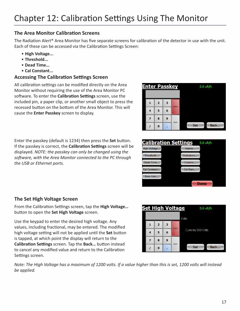
Accessing The Calibration Settings ScreenAll calibration settings can be modified directly on the Area Monitor without requiring the use of the Area Monitor PC software. To enter the Calibration Settings screen, use the included pin, a paper clip, or another small object to press the recessed button on the bottom of the Area Monitor. This will cause the Enter Passkey screen to display.
Enter the passkey (default is 1234) then press the Set button. If the passkey is correct, the Calibration Settings screen will be displayed. NOTE: the passkey can only be changed using the software, with the Area Monitor connected to the PC through the USB or Ethernet ports.
The Set High Voltage ScreenFrom the Calibration Settings screen, tap the High Voltage… button to open the Set High Voltage screen.
Use the keypad to enter the desired high voltage. Any values, including fractional, may be entered. The modified high voltage setting will not be applied until the Set button is tapped, at which point the display will return to the Calibration Settings screen. Tap the Back… button instead to cancel any modified value and return to the Calibration Settings screen.
Note: The High Voltage has a maximum of 1200 volts. If a value higher than this is set, 1200 volts will instead be applied.
Chapter 12: Calibration Settings Using The Monitor

18
The Set Threshold ScreenThe threshold sets the minimum size a detector pulse must be in units of mV, in order to be registered as a count. From the Calibration Settings screen, tap the Threshold… button to open the Set Threshold screen.
Use the keypad to enter the desired threshold. Any integer value may be entered. The modified threshold setting will not be applied until the Set button is tapped, at which point the display will return to the Calibration Settings screen. Tap the Back… button instead to cancel any modified value and return to the Calibration Settings screen.
The threshold can be set between 0 and 2000 mV . If a value higher than 2000 mV is set, 2000 mV will instead be applied.
If the threshold is set too low, excessive counts (due to electronic noise) may occur. If it is too high, counts may be missed. In gamma scintillation detectors, a threshold setting that is too high could also reduce the response to low-energy gamma radiation. Generally, a setting of approximately 50 mV is appropriate.
The Set Dead Time ScreenDead time is used to correct count rates for pulses that are “missed” due to pile up (in the case of scintillation detectors) or from gas recombination time (in the case of GM detectors). Dead-time correction keeps responses linear over the entire useful range of radiation intensities. From the Calibration Settings screen, tap the Dead Time… button to open the Set Dead Time screen.
Use the keypad to enter the desired dead time. Any value, including fractional, may be entered. The modified dead time setting will not be applied until the Set button is tapped, at which point the display will return to the Calibration Settings screen. Tap the Back… button instead to cancel any modified value and return to the Calibration Settings screen.
There are no restrictions on values to which the dead time can be set. However, note that the absolute maximum count rate that can be displayed is equal to 1/dead time.
Generally, scintillation detectors have dead times in the range of 1 to 4 µSec while GM tubes have dead times in the range of 10 to 100 µSec.
Setting the Dead Time to zero will disable dead-time correction.

19
The Set Cal Constant ScreenThe Calibration Constant is a conversion factor used to convert the detector’s count rate into units of exposure or dose rate. From the calibration Settings screen, tap the Cal Constant… button to open the Set Cal Constant screen.
Use the keypad to enter the desired Cal Constant. Any value, including fractional, may be entered. The modified Cal Constant setting will not be applied until the Set button is tapped, at which point the display will return to the Calibration Settings screen. Tap the Back… button instead to cancel any modified value and return to the Calibration Settings screen.
The Cal Constant is usually determined by exposing the detector to a known radiation field (in units of mR/h) of about 10 to 20% of the maximum value the detector is capable of detecting, noting the count rate in cps, and dividing cps by mR/h.
The Set Calibration Date ScreenThe Calibration Date is used to set the Calibration Date displayed in the System screen. From the Calibration Settings screen, tap the Cal Date… button to open the Set Calibration Date screen.
Use the keypad to enter the Calibration Date. Any value may be entered and no checking is performed regarding format. The modified Calibration Date will not be applied until the Set button is tapped, at which point the display will return to the Calibration Settings screen. Tap the Back… button instead to cancel any modified value and return to the Calibration Settings screen.
Setup and Calibration Sequence1. Disable alarms by setting all three alarm levels to zero.2. Set threshold and high voltage to appropriate values, generally with the Base Unit set to cpm or cps.3. Determine and set the Dead Time for the detector in use.4. Determine and set the Calibration Constant for the detector in use.5. Set the Base Unit to the desired minimum unit of measure.6. Confirm calibration by challenging with known levels of radiation and observing the indication.7. Set Alarm Levels, Alarm Indicators, and Communication Settings as desired.8. Set the Calibration Date.
Figure 9(6)
Figure 9(7)

20
Sensitivity, or Calibration Constant, is expressed in cps per mR/h (Counts Per Second for every milliroentgen the detector can detect) referenced to Cs-137. Mathematically the cps units cancel each other out leaving mR/h, as shown below.
For example, if you have collected 200 CPS with a GM tube that has a typical gamma sensitivity of 60 cpm per mR/h, you would divide the 200 cps by the 60 cpm per mR/h sensitivity. The cps cancels out and you are left with 200/60 mR/h = 3.33 mR/h (Note, however, that the Area Monitor performs this conversion internally.)
= cpscps
mR/h
cps1
XmR/hcps
= mR/h
Radiation Measurement UnitsSeveral different units are used to measure radiation, exposure and dosage.
Roentgen is the amount of X-radiation or gamma radiation that produces one electrostatic unit of charge in one cc of dry air at 0° C and 760 mm of mercury atmospheric pressure. One thousand milliroentgen (1,000 mR)= 1R. The Area Monitor can also displays in microroentgens per hour (millionths--µR/h), milliroentgens per hour (thousandths-mR/h) and kiloroentgens per hour (thousands—kR/h).
Rad is the unit of exposure to ionizing radiation equal to an energy of 100 ergs per gram of irradiated material. This is approximately equal to 1.07 roentgen.
Rem is the dosage received from exposure to a rad. It is the number of rads multiplied by the quality factor of the particular source of radiation. The rem and millirem are the most commonly-used measurement units of radiation dose in the U.S. 1 rem= 1 rad.
Sievert is the standard international measurement of dose. One sievert is equivalent to one hundred rems. A microsievert (μSv) is one millionth of a sievert. A unit of dose equivalent. 1 Sv= 100 roentgens, 10 µSv/h = 1 milliroentgen/h.
Curie is the amount of radioactive material that decays at the rate of 37 billion disintegrations per second, approximately the decay rate of one gram of radium. Microcuries (millionths of a curie) and picocuries (trillionths of a curie) are also often used as units of measurement.
Becquerel (Bq) is defined as the activity of a quantity of radioactive material in which one nucleus decays per second. 1 dps (one disintegration per second).
Converting CPS to mR/h
mR/h = cpssensitivity
200 cpscps
mR/h
= 3.33 mR/h60
Chapter 13: Unit Conversions

21
Display: Approx. 4 x 2.2 in. resistive touch screenNumeric Display: Five digits, numerals 1.35 in. tallOperating Ranges• AM-7149: 0.1 mR/hr to 16,000 mR/hr (0.1 to 160,000 µSv/hr) Using an Internally Mounted LND 7149
Energy Compensated GM Detector. External mounting also available• AM-7128: 0.1 µR/hr to 200 mR/hr (0.1 to 2000 µSv/hr) Using an Internally Mounted LND 7128 Energy
Compensated GM Detector. External mounting also available• AM-71313: 0.1 to 1500 mR/hr (0.1 – 15,000 µSv/hr) Using an Internally Mounted LND 71313 Energy
Compensated GM Detector. External mounting also available• AM-1X1NAI: 0.1 µR/hr to 10 mR/hr (0.1 µSv/hr to 100 µSv/hr) Using an Externally Mounted 1X1 NaI(Tl)
Scintillation Probe• AM-2X2NaI: 0.1 µR/hr to 2 mR/hr (0.1 to 20 µSv/hr) Using an Externally Mounted 2X2 Nal(Tl) Scintillation
ProbeMaximum Cable Lengths: GM Probes - 100 ft., Scintillation Probes - 50 ft.High Voltage: Adjustable from 200 to 1200 Volts in increments of 0.1 V Threshold: Adjustable from 0 to 2000 mV in increments of 1 mV Dead Time: Adjustable in increments of 0.01 uSecCalibration Constant: Infinitely adjustable in increments of 0.001 cps per mR/hBase Units: µR/h, mR/h, µSv/h, mSv/h, cpm, kcpm, cps, and kcpsAutorange: Will not go below base selected base unit Averaging Time: Automatic based on incoming count rate, from 4 to 20 seconds:Greater than 400 cps, averaging time = 2 sec201 to 400 = 4 sec101 to 200 = 6 sec68 to 100 = 8 sec51 to 67 = 10 sec41 to 50 =12 sec 35 to 40 =14 sec30 to 34 =16 sec26 to 39 =18 secLess than 25 = 20 secPower: External 12VDCBattery: Internal SLA battery, Typically run for 6 hours in non-alarm, 5 hours in continuous alarm conditionsCommunications: USB, EthernetSupported Detectors: GM, Energy-Compensated GM, NaI, CsI, LaCl, LaBr, and all other scintillation detectors
Appendix A: Technical Specifications

22
WARRANTOR: S.E. International, Inc., P.O. Box 39, 436 Farm Road, Summertown, TN 38483-0039, USA, (931) 964-3561
ELEMENTS OF LIMITED WARRANTY: S.E. International, Inc., warrants for 1 year the included detector and for 1 year all materials and craftsmanship in this product to be free from all defects with only the limitations set out below.
WARRANTY DURATION: The warranty shall terminate and be of no further effect one year after the original date of purchase of the product or at the time the product is: a) damaged or not maintained as is reasonable or necessary, b) modified, c) repaired by someone other than the warrantor for a defect or malfunction covered by this Warranty, d) contaminated with radioactive materials, or e) used in a manner or purpose for which the instrument was not intended or contrary to S.E. International, Inc.’s written instructions. This warranty does not apply to any product subjected to corrosive elements, misuse, abuse, or neglect.
STATEMENT OF REMEDY: In the event that the product does not conform to the warranty at any time while this warranty is effective, the Warrantor will repair the defect and return the instrument to you prepaid, without charge for parts or labor.
NOTE: While the product will be remedied under this warranty without charge, this warranty does not cover or provide for the reimbursement or payment of incidental or consequential damages arising from the use of or the inability to use this product. The liability of the company arising out of the supplying of this instrument, or its use, whether on warranties or otherwise, shall not in any case exceed the cost of correcting defects in the instrument, and after the said one year period all such liability shall terminate. Any implied warranty is limited to the duration of the written warranty.
PROCEDURE FOR OBTAINING PERFORMANCE OF WARRANTY: In the event that the product does not conform to this warranty, please write or call to the address above. S.E. International, Inc. will not accept contaminated instruments for calibration or repair under warranty or otherwise.
NOTE: Before using this instrument, the user must determine the suitability of the product for his or her intended use.
Appendix B: Limited Warranty

23
DB-9 Relay Connector The Radiation Alert Area Monitor can interface with external triggers and external strobes/horns via the relay connector, located on the bottom of the unit. The connector can accommodate three separate relays via the one connector. The corresponding pins for each three pin relay connection are detailed below.
Each relay is a switch, and can be set as an indicator for any of the alarm states. As an example, presume that Relay C has been assigned to the Failure Alarm. When there is no current failure alarm, there will be an open connection (i.e. an open switch) between pins 6 and 1, and a closed connection (i.e., a closed switch) between pins 6 and 2. If a failure alarm occurs these switches will be reversed: there will now be a closed connection between pins 6 and 1, and an open connection between pins 6 and 2.
Appendix C: Relays and Triggers Technical Info
To send a text message via email, you must use an SMS to email gateway. Just substitute a 10-digit cell number for ‘number’ for each carrier below: AT&T: [email protected] T-Mobile: [email protected] Verizon: [email protected] Sprint: [email protected] or [email protected] Virgin Mobile: [email protected] Tracfone: [email protected] Metro PCS: [email protected] Boost Mobile: [email protected] Cricket: [email protected] Nextel: [email protected] Alltel: [email protected] Ptel: [email protected] Suncom: [email protected] Qwest: [email protected] U.S. Cellular: [email protected]
Appendix D: How to Send a Text Message Via Email
Relay ACommon = pin 5Normally Open = pin 4Normally Closed = pin 9
Relay BCommon = pin 3Normally Open = pin 7Normally Closed = pin 8
Relay CCommon = pin 6Normally Open = pin 1Normally Closed = pin 2

24
Or fill out the form online at http://seintl.com/calibrations/
NAME MODEL NAME
COMPANY SERIAL NUMBER
ADDRESS
CITY
STATE, ZIP, & COUNTRY PHONE NUMBER
Please fill out this form and send it back to us if you would like to be notified of the NIST calibration renewal for your instrument to:
S.E. International, Inc.P.O. Box 39, 436 Farm Rd. Summertown, TN 38483
1.800.293.5759 | 931.964.3561 | Fax: 1.931.964.3564www.seintl.com | [email protected]
DATE PLACED IN SERVICE
Calibration Database Application