arr series three phase twelve pulse scr … series, three phase, twelve pulse manual ... circuit...
TRANSCRIPT
ARR SERIES
THREE PHASE, TWELVE PULSE SCR CHARGER
PRODUCT MANUAL
RS421
RS-421, Issue 6
UNIPOWER, LLC 3900 Coral Ridge Drive Coral Springs, FL 33065 Phone: +1- 954-346-2442 Toll Free: 1-800-440-3504 Web site – http://www.unipowerco.com
ARR SERIES, THREE PHASE, TWELVE PULSE MANUAL
RS-421, Issue 6 i
RECEIVING INSTRUCTIONS & GENERAL EQUIPMENT INFORMATION
Please Note: For your protection, the following information and the product manual should be read and thoroughly understood before unpacking, installing, or using the equipment.
UNIPOWER, LLC presents all equipment to the delivering carrier securely packed and in perfect condition. Upon acceptance of the package from us, the delivering carrier assumed responsibility for its safe arrival to you. Once you receive the equipment, it is your responsibility to document any damage the carrier may have inflicted, and to file your claim promptly and accurately.
1. PACKAGE INSPECTION 1.1 Examine the shipping crate or carton for any visible damage: punctures, dents, and any
other signs of possible internal damage. 1.2 Describe any damage or shortage on the receiving documents, and have the carrier sign
their full name. 1.3 If your receiving freight bill notes that a Tip-N-Tell is attached to your freight, locate it.
If the Tip-N-Tell arrow has turned even partially blue, this means the freight has been tipped in transport. Make sure the carrier notes this on your receipt before you sign for the freight.
2. EQUIPMENT INSPECTION 2.1 Within fifteen days, open the crate and inspect the contents for damages. While
unpacking, be careful not to discard any equipment, parts, or manuals. If any damage is detected, call the delivering carrier to determine appropriate action. They may require an inspection.
*SAVE ALL SHIPPING MATERIAL FOR THE INSPECTOR TO SEE!
2.2 After the inspection has been made, call UNIPOWER, LLC. We will determine if the
equipment should be returned to our plant for repair, or if some other method would be more expeditious. If it is determined that the equipment should be returned to UNIPOWER, LLC, ask the delivering carrier to send the packages back to UNIPOWER, LLC at the delivering carrier's expense.
2.3 If repair is necessary, we will invoice you for the repair so that you may submit the bill
to the delivering carrier with your claim form.

ARR SERIES, THREE PHASE, TWELVE PULSE MANUAL
RS-421, Issue 6 ii
2.4 It is your responsibility to file a claim with the delivering carrier. Failure to properly file a claim for shipping damages may void warranty service for any physical damages later reported for repair.
3. HANDLING
Equipment can be universally heavy or top-heavy. Use adequate humanpower or equipment for handling. Until the equipment is securely mounted, be careful to prevent the equipment from being accidentally tipped over.
4. NAMEPLATE
Each piece of UNIPOWER, LLC equipment is identified by a part number on the nameplate. Please refer to this number in all correspondence with UNIPOWER, LLC.
5. INITIAL SETTINGS
All equipment is shipped from our production area fully checked and adjusted. Do not make any adjustments until you have referred to the technical reference or product manual.
6. SPARE PARTS
To minimize downtime during installation or operation, we suggest you purchase spare fuses, circuit boards and other recommended components as listed on the Recommended Spare Parts List in the back of the product manual. If nothing else, we strongly recommend stocking spare fuses for all systems.

ARR SERIES, THREE PHASE, TWELVE PULSE MANUAL
RS-421, Issue 6 iii
ISSUE HISTORY
ISSUE PAGE(S)
ALTERED DESCRIPTION ISSUED BY
/DATE 6 ALL Updated UNIPOWER logo, verbiage, & contact
information. See PCO# 44445. WD
6/22/17
DOCUMENT SUMMARY
This document is the User Product Manual for the Twelve Pulse ARR. PURPOSE This manual includes instructions for installing, operating, and maintaining the Twelve Pulse ARR.
LEGAL DISCLAIMER UNIPOWER, LLC, believes that all information contained in this manual is accurate and reliable. However, this information does not constitute any guaranty or warranty by UNIPOWER, nor does it make UNIPOWER responsible for any damage that might occur during the installation, use or maintenance of the equipment described in this manual. UNIPOWER, LLC, also does not guarantee that the suggested equipment uses given in this manual do not infringe upon any existing or pending patents. Those who install, use, and maintain this equipment, should not assume that all possible safety measures that should be taken with this equipment are mentioned in this manual. Furthermore, no one should assume that no other precautionary measures may be required for safe installation, use and maintenance of this equipment, where unusual environmental conditions or circumstances dictate otherwise.
ARR SERIES, THREE PHASE, TWELVE PULSE MANUAL
RS-421, Issue 6 1
Table of Contents 1 INTRODUCTION .......................................................................................................................................... 3
1.1 Purpose and Use..................................................................................................................................... 3 1.2 Identification ............................................................................................................................................ 4
2 INSTALLATION ............................................................................................................................................ 4
2.1 Unpacking ............................................................................................................................................... 4 2.2 Location ................................................................................................................................................... 4 2.3 Mounting .................................................................................................................................................. 4 2.4 Power Source .......................................................................................................................................... 5 2.5 Connections ............................................................................................................................................ 5
2.5.1 CABINET DIMENSIONS ................................................................................................................ 7 2.6 Preliminary Adjustments ......................................................................................................................... 8
2.6.1 Float Voltage Adjustment ............................................................................................................... 8 2.6.2 Equalize Voltage Adjustment .......................................................................................................... 9 2.6.3 Current Limit Adjustment ................................................................................................................ 9 2.6.4 High Voltage Shutdown Adjustment ............................................................................................. 10
3 OPERATION ............................................................................................................................................... 11
3.1 Starting and Stopping ............................................................................................................................ 11 3.2 Meters ................................................................................................................................................... 12 3.3 Float-Equalize Operation ....................................................................................................................... 12 3.4 Description of Operation ....................................................................................................................... 12 3.5 Specific Operating Characteristics ........................................................................................................ 13
4 ROUTINE MAINTENANCE ......................................................................................................................... 15
5 CORRECTIVE MAINTENANCE ................................................................................................................. 15
5.1 Voltage Check points ............................................................................................................................ 15 5.2 Balancing Procedure ............................................................................................................................. 15 5.3 Specific Problem Chart ......................................................................................................................... 19 5.4 Instruction Notes ................................................................................................................................... 21
5.4.1 Checking of Potentiometers ......................................................................................................... 21 5.4.2 Checking of Diodes and Silicon Controlled Rectifiers .................................................................. 21 5.4.3 Checking the Current Transformer ............................................................................................... 22 5.4.4 Checking the Auxiliary Transformer ............................................................................................. 23 5.4.5 Checking DC Filter Capacitors ..................................................................................................... 24 5.4.6 Checking of Printed Circuit Control Cards .................................................................................... 24
6 CIRCUIT DESCRIPTIONS ......................................................................................................................... 26
6.1 Basic Control ......................................................................................................................................... 26
7 ACCESSORIES AND OPTIONAL EQUIPMENT ........................................................................................ 31
SERVICE HINT Check all electrical
connections for tightness at time of installation
ARR SERIES, THREE PHASE, TWELVE PULSE MANUAL
RS-421, Issue 6 2
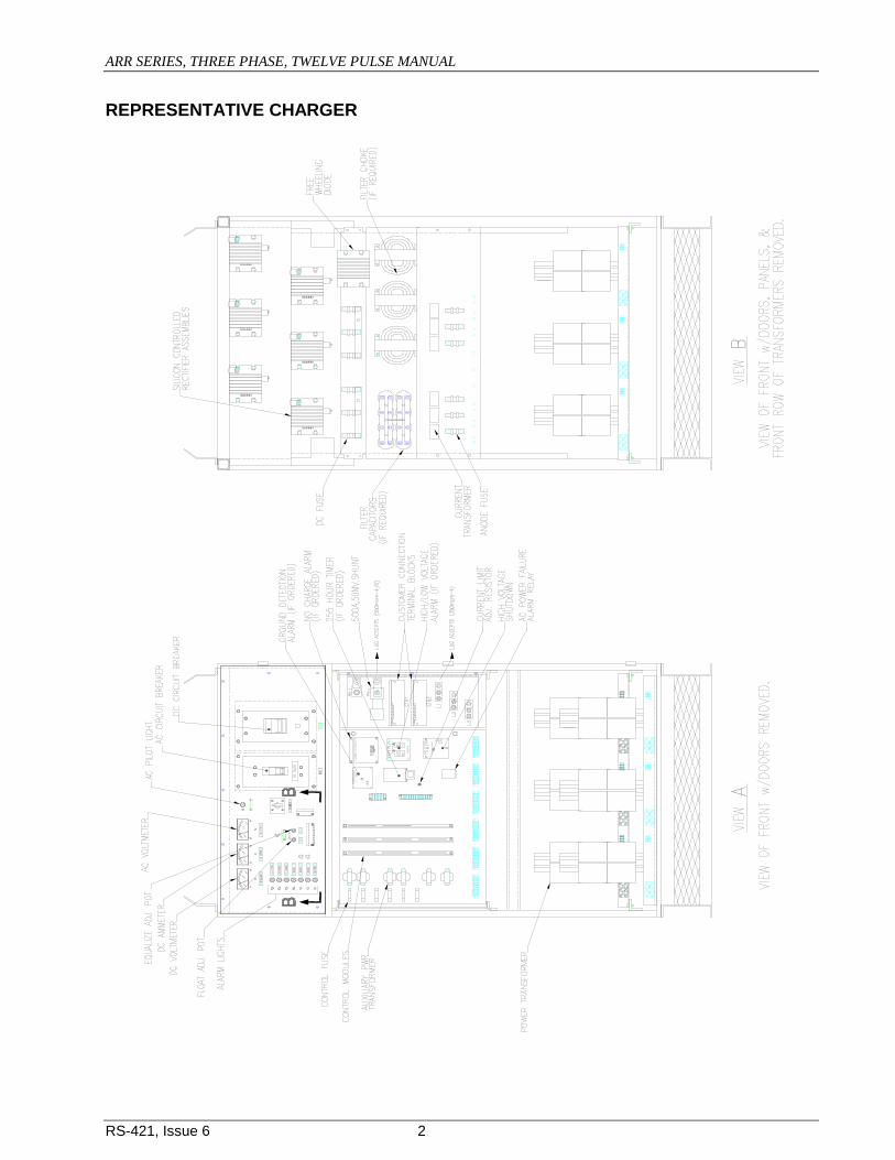
REPRESENTATIVE CHARGER

ARR SERIES, THREE PHASE, TWELVE PULSE MANUAL
RS-421, Issue 6 3
1 INTRODUCTION 1.1 Purpose and Use The purpose of the UNIPOWER AutoReg® battery charger is the conversion of AC power to DC power for the proper maintenance of a battery in the fully charged condition. The battery is maintained in the fully charged state, because the AutoReg® will continually deliver a DC output equal to the given load, provided that load does not exceed the DC output rating indicated on the nameplate. The battery then is said to be in float service. Since, unless there is an AC power failure, the battery will not be required to provide the power needed for the load, it remains fully charged. In the AutoReg® charger, when the AC line supply is within the limits of 10% above or below the AC voltage rating on the nameplate, and 5% above or below the AC frequency rating on the nameplate, the charger will maintain a steady DC output voltage within ± ½%, for any load from 0% to 100%. The efficiency of the charger is shown by the following graph.
On the AutoReg® charger, the float and equalize voltages can be adjusted within the range of 10% above or below the nominal voltages, which are factory set. The AutoReg® charger has incorporated into its control circuitry a current-limit system. This is factory set at 105% of the rated output. The following graph shows the effectiveness of the current-limit.
ARR SERIES, THREE PHASE, TWELVE PULSE MANUAL
RS-421, Issue 6 4
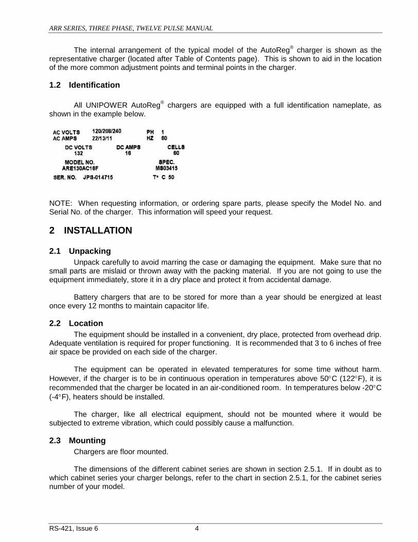
The internal arrangement of the typical model of the AutoReg® charger is shown as the representative charger (located after Table of Contents page). This is shown to aid in the location of the more common adjustment points and terminal points in the charger.
1.2 Identification All UNIPOWER AutoReg® chargers are equipped with a full identification nameplate, as shown in the example below.
NOTE: When requesting information, or ordering spare parts, please specify the Model No. and Serial No. of the charger. This information will speed your request.
2 INSTALLATION
2.1 Unpacking Unpack carefully to avoid marring the case or damaging the equipment. Make sure that no small parts are mislaid or thrown away with the packing material. If you are not going to use the equipment immediately, store it in a dry place and protect it from accidental damage. Battery chargers that are to be stored for more than a year should be energized at least once every 12 months to maintain capacitor life.
2.2 Location The equipment should be installed in a convenient, dry place, protected from overhead drip. Adequate ventilation is required for proper functioning. It is recommended that 3 to 6 inches of free air space be provided on each side of the charger. The equipment can be operated in elevated temperatures for some time without harm. However, if the charger is to be in continuous operation in temperatures above 50°C (122°F), it is recommended that the charger be located in an air-conditioned room. In temperatures below -20°C (-4°F), heaters should be installed. The charger, like all electrical equipment, should not be mounted where it would be subjected to extreme vibration, which could possibly cause a malfunction.
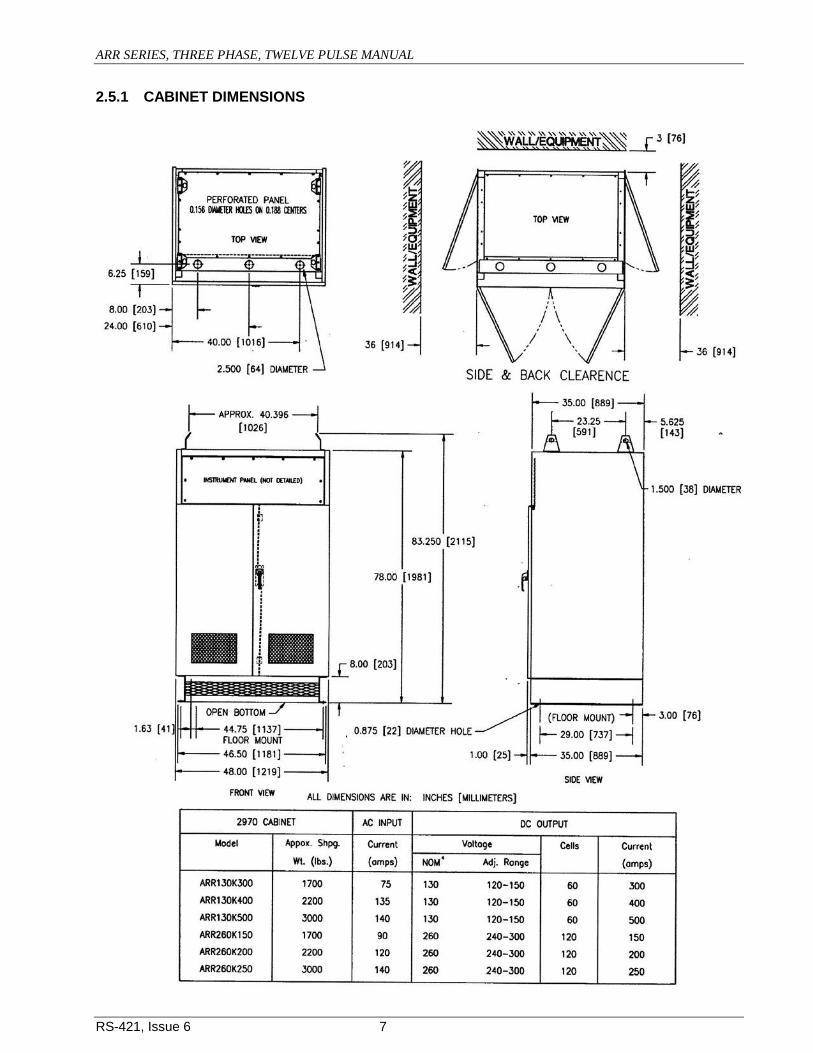
2.3 Mounting Chargers are floor mounted. The dimensions of the different cabinet series are shown in section 2.5.1. If in doubt as to which cabinet series your charger belongs, refer to the chart in section 2.5.1, for the cabinet series number of your model.

ARR SERIES, THREE PHASE, TWELVE PULSE MANUAL
RS-421, Issue 6 5
2.4 Power Source To function properly, the AC supply voltage (i.e. the AC input line) must be within the limits of ±10% of the voltage rating stamped on the nameplate; and ±5% of the frequency rating (frequency is indicated by Hertz on nameplate). The chart in section 2.5.1 lists the possible AC supply voltages and current draws for all standard models of the ARR AutoReg® charger. The cabinet series is also indicated on this chart, as well as the DC voltage range. If the source voltage is other than the rated value, or if the sustained AC voltage fluctuations are beyond the range of ±10%, contact the nearest sales office of UNIPOWER Technologies.
2.5 Connections The charger input and output connection points are reached through the hinged front or removable top panel. The AC input connections are made to the AC terminal points on the terminal board. The DC output connections are located opposite the AC connection points on the terminal board. Both the AC and DC connection points are clearly marked on the board. Follow carefully this procedure for making AC and DC connections to the charger:
1. Place the AC circuit breaker in the “OFF” position. 2. The battery should remain disconnected and the DC circuit breaker placed in the “OFF”
position. 3. Place the “NORMAL-EQUALIZE” toggle switch in the “NORMAL” position.
4. Check the card (pictured above) supplied with the charger to see if the transformer primary terminal block is connected in the proper sequence for your incoming AC line voltage.
If you have a different line voltage, consult your local UNIPOWER agent or Field Service at 1-800-440-3504.
5. Connect the incoming AC leads to the AC terminal blocks located on the terminal board. (Be sure that the AC input leads are connected to points marked L1, L2, and L3.)
6. Connect the DC positive and the negative leads from the battery to the designated terminal points on the terminal board. Make sure all connections are tight, and that the correct polarity has been observed (i.e. Positive to Positive and Negative to Negative)
7. CLOSE THE DC CIRCUIT BREAKER. This energizes the charger filter capacitors connected across the DC output. The DC voltmeter on the front panel should read the battery voltage and ammeter should read zero or slightly above.
ARR SERIES, THREE PHASE, TWELVE PULSE MANUAL
RS-421, Issue 6 6
8. Close the AC circuit breaker. The DC ammeter on the front panel will register the current flow and the charger voltage will gradually increase as your battery charges to the floating voltage level, which was set at the factory.
9. (Acceptable alternate sequence) Close the ac circuit breaker. The charger output voltage slowly rises to the float voltage set point. The filter capacitors will be charged by the charger.
10. Close the dc breaker. The dc ammeter will register the current flow to the load and battery. It is possible to damage the rectifier stack or blow the anode fuses if the above procedures are not followed.
ARR SERIES, THREE PHASE, TWELVE PULSE MANUAL
RS-421, Issue 6 7
2.5.1 CABINET DIMENSIONS

ARR SERIES, THREE PHASE, TWELVE PULSE MANUAL
RS-421, Issue 6 8
2.6 Preliminary Adjustments
All adjustments are factory set. The settings are indicated by the red card (pictured here) attached on the inside front of the charger.
However, you may wish to change some of the following settings to fit your particular battery. (The chart, shown below, shows the proper float and equalize voltages for the different battery types.
Proper Float & Equalize Voltages Cell Voltages
Type Float Equalize Lead Antimony 2.15 2.33 Lead Calcium 2.17-2.20 2.33
Not required Nickel-Cadmium 1.43 1.55 Nickel-Iron 1.50-1.55 1.60-1.65
2.6.1 Float Voltage Adjustment The float potentiometer controls the floating voltage of the charger when either the toggle switch is in the “NORMAL” or “FLOAT” position or the optional equalize timer is in the “OFF” condition. NOTE: Both “FLOAT” and “EQUALIZE” Potentiometers are 10-turn devices. The adjustment control (potentiometer) for float voltage is located on the front of your charger, marked either FL or FLOAT. By turning the potentiometer clockwise, you increase the float voltage. If you turn the potentiometer counterclockwise, you decrease the float voltage. In order to correctly adjust the float voltage the battery should be in a fully charged condition with some load connected. While the unit is in operation, adjust the float potentiometer to float voltage desired. (The voltage reading is indicated on the charger’s voltmeter.) The float voltage will depend upon the type of battery, and the type of service for which the battery is used (e.g. communications). NOTE: Keep the toggle switch in the “FLOAT” position during regular operation.

ARR SERIES, THREE PHASE, TWELVE PULSE MANUAL
RS-421, Issue 6 9
2.6.2 Equalize Voltage Adjustment The potentiometer for this adjustment is also on the front of the charger marked either EQ or EQUALIZE. Move the toggle switch to the “EQUALIZE” position or place the optional equalize timer in the “ON” condition. Then, with the charger in operation, as it was during float voltage adjustment, make your equalize voltage adjustment. The equalize voltage potentiometer works exactly as the float voltage potentiometer - a clockwise turn increases voltage; a counterclockwise turn decreases voltage. The equalize voltage setting will depend upon the type of battery used (refer to chart), and the maximum limiting voltage of the connected load equipment. NOTE: When manually selecting between “FLOAT” and “EQUALIZE”, always return to “FLOAT” condition at the end of the equalizing charge.
2.6.3 Current Limit Adjustment The current limit is factory set at 105% of the rated output of the charger. If a higher current limit setting is desired, the potentiometer may be set within the range of 100% to 115% of the rated output. However, this maximum percentage (115%) should not be maintained continuously. The charger can only be guaranteed for two hours at a 50°C ambient temperature, when operating at 115% of the rated output. If the current limit setting of 115% is exceeded, or the charger is operated at this output longer than two hours, the charger warranty will become null and void. Any adjustments above 115% of the rated output should be made by a UNIPOWER service personnel. If the current limit setting is changed without authorization by UNIPOWER warranty will become null and void. The current limit potentiometer, which is located on the 9-point control board, is adjusted in the following manner:
1. Remove AC power from the charger by opening the AC circuit breaker. 2. Allow battery voltage to drop a few volts. This will discharge the battery enough to
require the charger to operate in the current limit range, when it is turned on. If there is a dummy load available, adjust the load until 105% of the charger rating is reached.
3. Close the AC circuit breaker allowing AC power to the charger. The charger will now be operating in the current limit range of 105% of the rated output (factory set).
4. Now, slowly adjust the potentiometer shaft counterclockwise (some pressure may be needed when first turning the shaft until the factory seal is broken), until the current reaches 105%, or the desired current below 105% of the charger’s rated output. For example, on a 200-amp charger, stop when the current reaches 210 amps.
5. Check setting by repeating steps 1, 2, and 3. CAUTION: Do not attempt to set float or equalize voltages until the charger drops out of the current limit range, or until the charger output returns to normal.
ARR SERIES, THREE PHASE, TWELVE PULSE MANUAL
RS-421, Issue 6 10
2.6.4 High Voltage Shutdown Adjustment The high voltage shutdown (HVS) is designed to operate if the charger output goes to a high voltage. There are two different high voltage shutdown systems. One system uses a latching relay and the other system uses a shunt trip circuit breaker on the input of the charger. To determine which system is installed in the charger either consult the charger schematic and wiring diagram or check the charger for the hardware described for the each of the shutdown systems. LATCHED RELAY SYSTEM: When a high voltage is sensed, the latching relay system’s high voltage shutdown board disconnects the auxiliary voltage transformers. Disconnecting the auxiliary voltage transformers results in no control power for the charger causing the charger to shut off. The high voltage shutdown is a latching device that must be manually reset when the unit is activated. A reset button is located on the face of the high voltage shutdown unit. When reset the charger will restart. If the unit shuts down again, check for the cause of the high voltage condition. Unless otherwise requested, the high voltage shutdown is factory set to 148 volts dc for a 130-volt charger or 295 volts dc for a 260-volt charger. It is recommended that the shutdown setting be kept at least 15% above the equalize voltage setting. In order to check that your high voltage shutdown is properly set, follow this procedure:
1. Disconnect the battery if possible and apply a small load, approximately 1 amp, to the charger.
2. Connect an ohmmeter on terminals 7 and 8, the C-NO (common-normally open) contacts; and jumper terminals 3 and 4.
3. Place the charger in equalize. 4. Use the equalize adjustment to slowly raise the charger output voltage until the ohmmeter
reads no resistance. This would mean that under normal operation as a battery charger, the high voltage shutdown would have been activated and the charger would have consequently shutdown.
5. If the high voltage shutdown is properly set per the factory levels, the ohmmeter should show no resistance at 152 volts dc for a 130-volt charger or 305 volts dc for a 260-volt charger.
However, if these readings are not obtained, or a higher setting is desired, follow this procedure: NOTE: Be sure to reset the high voltage shutdown before beginning these steps.
1. Repeat steps 1, 2, and 3 of the check procedure. 2. Turn the Voltage Adjustment Potentiometer of the high voltage shutdown completely
clockwise. 3. Adjust the equalize voltage until the desired “trip” voltage is obtained. 4. Then slowly turn the Voltage Adjustment Potentiometer of the high voltage shutdown
counter-clockwise until the ohmmeter reads no resistance. 5. Turn the equalize voltage down, reset the relay, and repeat step 3 as a check for the
correct shutdown setting. 6. On high voltage shutdown units with variable time delay, turn the delay time adjusting
potentiometer full counter-clockwise until the voltage trip point is adjusted. Then return the delay time to the desired setting and recheck settings.
SHUNT TRIP SYSTEM: With the shunt trip system the high voltage condition causes the shutdown board to energize a relay on the board. The relay operates energizing the shunt trip coil on the ac

ARR SERIES, THREE PHASE, TWELVE PULSE MANUAL
RS-421, Issue 6 11
circuit breaker causing the breaker to trip and shut off the charger. The high voltage shutdown circuit board for the shunt trip system may be silk-screened “High Voltage Alarm.“ Once activated the high voltage shutdown is reset by moving the ac circuit breaker operator from the “tripped” position to the “off” position and then to the “on” position. This will restart the charger. If the breaker trips again, check for the cause of the high voltage condition. Unless otherwise requested, the high voltage shutdown is factory set to 148 volts dc for a 130-volt charger or 295 volts dc for a 260-volt charger. It is recommended that the shutdown setting be kept at least 15% above the equalize voltage setting. In order to check that the high voltage shutdown is properly set, follow this procedure:
1. Disconnect the battery if possible and apply a small load, approximately 1 amp, to the charger.
2. Place the charger in equalize and use the equalize adjustment to slowly raise the charger output voltage to the setpoint.
3. The ac breaker will trip when the setpoint is reached. 4. If the high voltage shutdown is properly set per the factory levels, the ac circuit breaker
will trip at 152 volts dc for a 130-volt charger or 305 volts dc for a 260-volt charger. Note: The setpoint can be checked without tripping the ac breaker by disconnecting one of the connections to the shunt trip coil and listening for the relay to energize or measuring voltage at the relay contact(s). However, if these readings are not obtained, or a higher setting is desired, follow this procedure: NOTE: Be sure to reset the charger before beginning these steps.
1. Repeat steps 1 and 2 of the check procedure. 2. Turn the voltage setpoint adjustment of the high voltage shutdown (alarm) board
completely clockwise. 3. Adjust the equalize voltage until the desired “trip” voltage is obtained. 4. Then slowly turn the voltage setpoint adjustment counter-clockwise until the ac circuit
breaker (or relay) operates. 5. Turn the equalize voltage down, reset the ac circuit breaker, if necessary, and repeat step
3 as a check for the correct shutdown setting. 6. Reconnect the shunt trip, if necessary, and re-set the equalize voltage when setting the
high voltage shutdown is completed.
3 OPERATION
3.1 Starting and Stopping After the charger has been installed and the connections made, to activate the unit, simply close the DC circuit breaker (move the DC switch to “ON” position) then close the AC circuit breaker (move the AC switch to “ON” position). (Acceptable alternate sequence) Close the ac circuit breaker. The charger output voltage slowly rises to the float voltage set point. The filter capacitors will be charged by the charger. Close the dc breaker. The dc ammeter will register the current flow to the load and battery. CAUTION: It is recommended to always close the DC breaker before the AC breaker so that the filter cans (if the unit is filtered) are charged from the battery.
ARR SERIES, THREE PHASE, TWELVE PULSE MANUAL
RS-421, Issue 6 12
It is possible to damage the rectifier stack or blow the anode fuses if above procedures are not followed.
3.2 Meters The DC output voltage is indicated by a voltmeter on the front panel of the charger. The DC output current is shown by an ammeter on the front panel.
3.3 Float-Equalize Operation The float-equalize switch on the front panel of the charger should remain in the “NORMAL” (float) position for regular or float operation. When higher than a normal charge is desired on a discharged battery, a higher DC voltage may be obtained by putting the toggle switch or optional timer in the “EQUALIZE” position. Refer to the chart in section 2.6 for the proper float and equalize voltages for specific battery types.
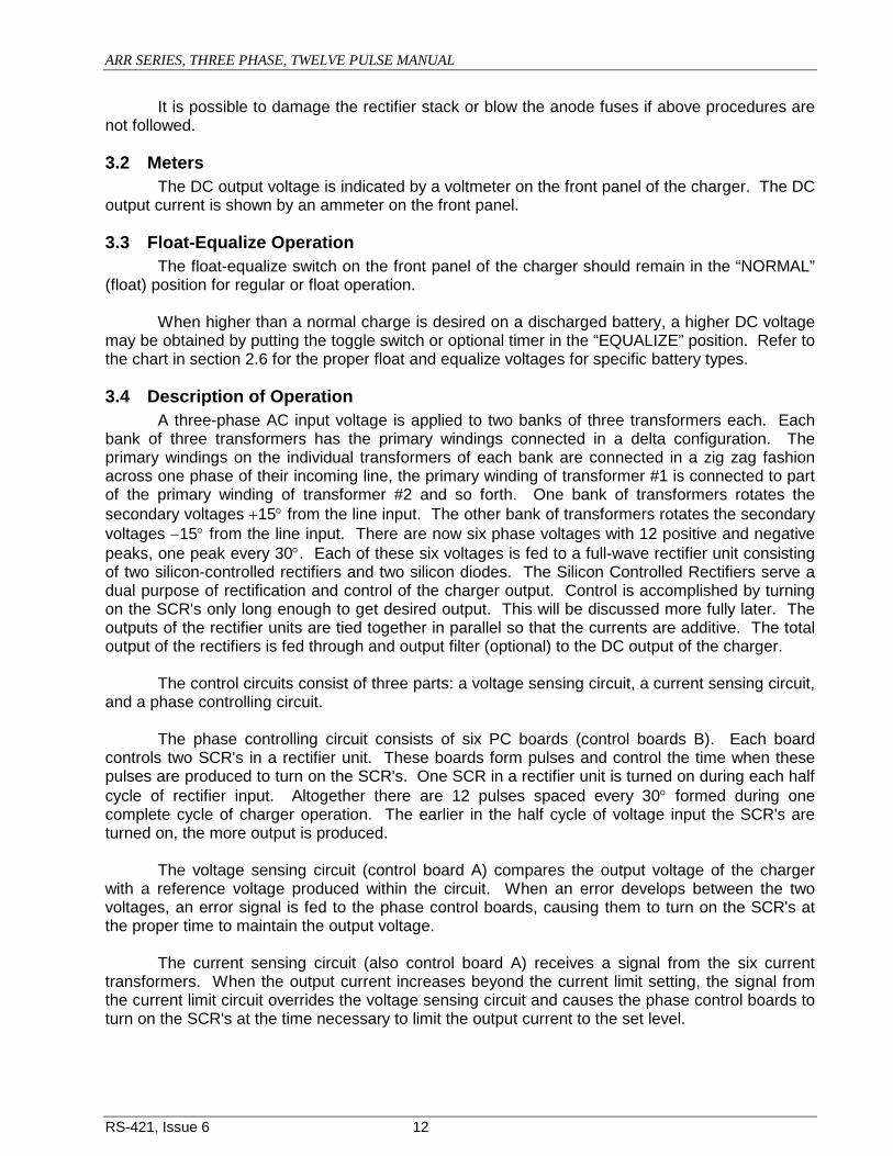
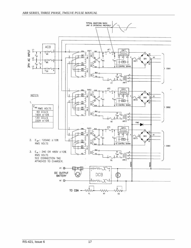
3.4 Description of Operation A three-phase AC input voltage is applied to two banks of three transformers each. Each bank of three transformers has the primary windings connected in a delta configuration. The primary windings on the individual transformers of each bank are connected in a zig zag fashion across one phase of their incoming line, the primary winding of transformer #1 is connected to part of the primary winding of transformer #2 and so forth. One bank of transformers rotates the secondary voltages +15° from the line input. The other bank of transformers rotates the secondary voltages −15° from the line input. There are now six phase voltages with 12 positive and negative peaks, one peak every 30°. Each of these six voltages is fed to a full-wave rectifier unit consisting of two silicon-controlled rectifiers and two silicon diodes. The Silicon Controlled Rectifiers serve a dual purpose of rectification and control of the charger output. Control is accomplished by turning on the SCR's only long enough to get desired output. This will be discussed more fully later. The outputs of the rectifier units are tied together in parallel so that the currents are additive. The total output of the rectifiers is fed through and output filter (optional) to the DC output of the charger. The control circuits consist of three parts: a voltage sensing circuit, a current sensing circuit, and a phase controlling circuit. The phase controlling circuit consists of six PC boards (control boards B). Each board controls two SCR's in a rectifier unit. These boards form pulses and control the time when these pulses are produced to turn on the SCR's. One SCR in a rectifier unit is turned on during each half cycle of rectifier input. Altogether there are 12 pulses spaced every 30° formed during one complete cycle of charger operation. The earlier in the half cycle of voltage input the SCR's are turned on, the more output is produced. The voltage sensing circuit (control board A) compares the output voltage of the charger with a reference voltage produced within the circuit. When an error develops between the two voltages, an error signal is fed to the phase control boards, causing them to turn on the SCR's at the proper time to maintain the output voltage. The current sensing circuit (also control board A) receives a signal from the six current transformers. When the output current increases beyond the current limit setting, the signal from the current limit circuit overrides the voltage sensing circuit and causes the phase control boards to turn on the SCR's at the time necessary to limit the output current to the set level.

ARR SERIES, THREE PHASE, TWELVE PULSE MANUAL
RS-421, Issue 6 13
There is another board (control board C) that is part of the control circuits. This board is connected between the B boards and the A board, and also between the current transformers and the A board. Its purpose is to tie the signal from the A board to the B boards, to tie the signal from the current transformers to the A board, and to set the outputs from all the rectifier units at equal levels. Power is provided to the Control Circuits by six auxiliary transformers. The primaries of these transformers are connected to auxiliary windings on the power transformers. The secondary voltages of the auxiliary voltage transformers are in phase with the power transformer voltages that supply the rectifier units. These voltages supply the phase control boards, which in turn control the rectifier units having supply voltages with the same phase. The A board is supplied from its interconnections with the B boards. An AC circuit breaker is provided on the input to the charger. The breaker provides overload and short circuit protection for the charger and serves as the disconnecting means for AC power. There are anode fuses on the rectifier units to protect the rectifier against fault currents. A snubber, consisting of a capacitor and resistor in series, is connected across each rectifier unit to prevent high voltage spikes from appearing across the rectifier unit. A DC circuit breaker is provided on the output of the charger to protect against external faults and to allow connection of the battery to the charger without causing arcing due to the capacitors charging.
3.5 Specific Operating Characteristics 1. The use of six voltage phases on the input to the rectifier units greatly reduces AC ripple on
the DC output of the charger. 2. If the components associated with one of the six voltage phases become damaged, the
current limit setting will decrease proportionately so that protection is still provided for the remaining phases.
3. The charger is provided with soft-start upon initial energization. This is important when the charger is subjected to very high loads.
See Block Diagram below.

ARR SERIES, THREE PHASE, TWELVE PULSE MANUAL
RS-421, Issue 6 14

ARR SERIES, THREE PHASE, TWELVE PULSE MANUAL
RS-421, Issue 6 15
4 ROUTINE MAINTENANCE CAUTION: The charger will have live terminals unless both the AC power source and the battery are disconnected. Be careful, to avoid electric shocks and burns.
a. Ventilation is of prime importance. Check the area around the charger; be sure that nothing interferes with the free flow of air.
b. Check for dust deposits. Dust on the heat radiating surfaces and contacts of the charger
will greatly reduce heat dissipation. Dust and other accumulations should be removed regularly.
c. The area around the charger should be kept dry. On occasion, condensation may form
especially when the unit is idle; this should be cleaned to prevent fungus growth.
d. Connections at the terminals should be clean, and should be tight. Heating of terminals is a definite indication of corroded or loose terminal connections. Fuse clips particularly are subject to overheating and corroding. They should be checked regularly for proper tension and cleanliness of contact area.
e. Float and equalize voltage should be checked occasionally and readjusted if necessary.
(Refer to Float and Equalize Voltage Adjustment in sections 2.6.1 & 2.6.2.)
f. When possible, the current limit operation should be checked. If current limit occurs when the load current is too high, overloads may damage the unit. (Refer to Current Limit Adjustment in section 2.6.3, if necessary.)
g. To insure accurate voltage readings, periodically check the floating voltage as shown on the charger’s panel voltmeter, using a portable standard voltmeter. If necessary, adjust the panel voltmeter to agree with the standard voltmeter by using the zero adjustment, located on the face of the charger’s panel voltmeter.
5 CORRECTIVE MAINTENANCE
5.1 Voltage Check points When there is no DC output on the charger, check the following list for possible failure points in the charger. (The schematic located between sections 5.2 & 5.3, indicates points where a voltage reading should be taken. The chart on the schematic lists the proper voltages to be found at each point.)
5.2 Balancing Procedure NOTE: BALANCING PROCEDURE MUST BE PERFORMED AFTER ALL FIELD MODIFICATIONS.
1. Remove five 18 point B control boards. Energize the charger according to instructions in the manual and load the charger to 1/6 of rated output.
2. Connect the probe of the oscilloscope to the AC inputs of the active SCR bridge.
The voltage waveform should look like Fig. 1. If the horizontal spacings in the waveform are unequal, adjust the reactor balance pot located on the 18 point “B” control board for that phase so that the pattern is symmetrical. Repeat this step for the remaining SCR bridges, operating unit on one phase only for each balancing process. Mark each board with the phase it was tested in.

ARR SERIES, THREE PHASE, TWELVE PULSE MANUAL
RS-421, Issue 6 16
3. Replace all boards in their respective phases. Connect the probe of the scope to the
DC output terminals and examine the ripple pattern. The waveform should look like Fig. 2. To balance the pattern, readjust the reactor balance pots in Step 1.
4. Adjust Pot P1 on C control board to balance phases 1, 2, & 3 with phases 4, 5, & 6.
ARR SERIES, THREE PHASE, TWELVE PULSE MANUAL
RS-421, Issue 6 17
ARR SERIES, THREE PHASE, TWELVE PULSE MANUAL
RS-421, Issue 6 18

ARR SERIES, THREE PHASE, TWELVE PULSE MANUAL
RS-421, Issue 6 19
5.3 Specific Problem Chart PROBLEM POSSIBLE CAUSES SOLUTION
A. No Voltage (E) at power transformer secondary (sec.)
1. Open AC circuit breaker. 2. Open winding (s) on power transformer
a. Close AC circuit breaker. b. Replace power transformer.
B. Incorrect E sec.
1. Incorrect AC input for the charger connections
a. Refer to Connections #4 in section 2.5.
C. Correct E sec. but no E sec. on output of Anode fuses.
1. Open Anode fuses. a. Replace Anode fuse. If it blows again, see E., 1., a. below.
D. E sec. on output of Anode fuses, but still no DC output from charger.
1. Open control fuse (to check control fuse, look for proper voltage at auxiliary transformer E AFX primary.)
2. Primary winding of auxiliary voltage
transformer is shorted (indicated by a blown control fuse.)
3. Current Limit Potentiometer open. 4. Defective Printed Circuit Control Cards.
a. Replace control fuse and check secondary voltage of AXF (Auxiliary Transformer). See instruction 5.4.4.
a. Replace auxiliary transformer. a. See instruction 5.4.6. a. Replace printed cards or see
instruction 5.4.6.
E. Loss of output Voltage and Current, or Low Output Current.
1. Anode Fuse(s) open. (This can be caused by a high current surge, which is brought about by the filter cans being charged when the AC breaker is closed before the DC breaker, in energizing the charger unit).
a. Replace with equivalent fuse. (See parts list.) If anode fuse blows again, and proper "turn-on" procedure was followed; check for: 1. shorted diodes & SCR’s
(See instruction 5.4.2). 2. defective control boards
(See instruction 5.4.6).
2. Control Fuse open. 3. Auxiliary Voltage transformer winding(s)
open. 4. Open SCR’s Anode to Cathode and/or
Diodes. 5. Open Current Limit Resistor 6. Shorted gates or open gates. 7. Loose or broken connections 8. Printed circuit boards defective. 9. Shorted filter capacitor(s).
a. Replace with similar rated fuse (See parts list). If fuse blows again, check the primary of the auxiliary transformer (AXF) with a voltmeter (refer to Voltage Checkpoint Chart).
a. See instruction 5.4.4. a. See instruction 5.4.2. a. Replace a. See instruction 5.4.2. a. Check for signs of overheating
or corrosion, and repair connections.
a. Replace or see 5.4.6. a. See instruction 5.4.5.
ARR SERIES, THREE PHASE, TWELVE PULSE MANUAL
RS-421, Issue 6 20
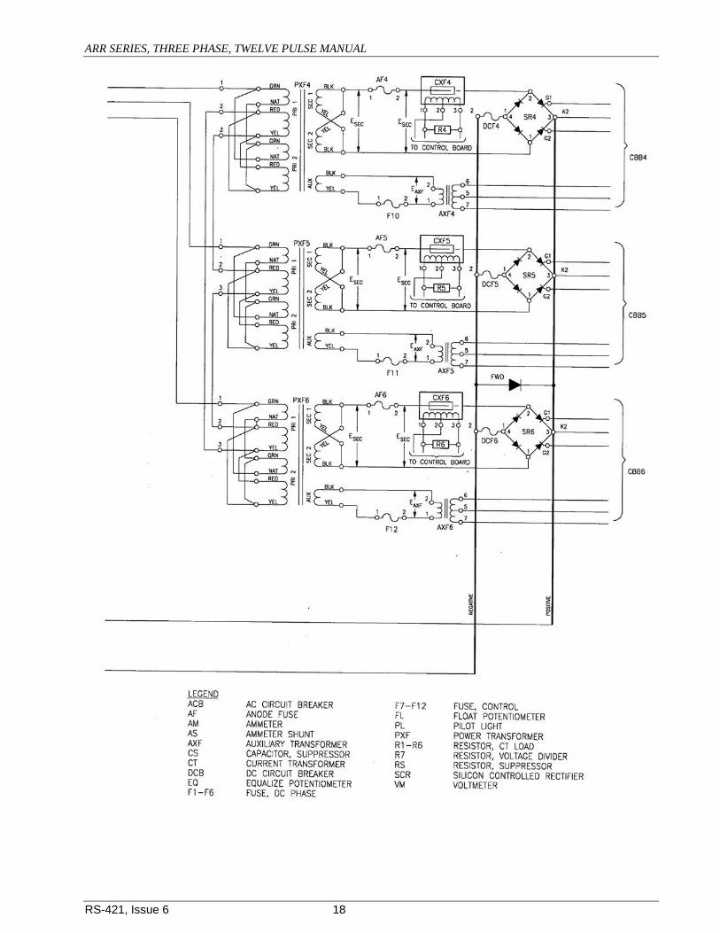
F. Low Output Voltage
Adjustable Within 10% of Rated Voltage
1. Low AC Input Voltage a. Unit Connected for 240 Volts AC and Input is below 216 Volts AC. b. Unit is Connected for 480 Volts AC and Input is Below 430 Volts AC.
2. One SCR, SCR gate and/or one diode
open (however, not both in the same leg of the stack).
3. Printed circuit boards defective. 4. Half-wave operation. If oscilloscope is
available, check voltage wave form at AC inputs to Bridge rectifier; the wave form should look like:
Input should be ± 10% of Nameplate Voltages. Input Voltage Must be Increased to fall within ± 10% of Nameplate Voltage.
a. See Instruction 5.4.2. a. Replace or see 5.4.6. a. If waveform shows only one
break, check aux. volt. trans. for voltage from pt. 7 to 5 & 6 to 5. Each should read 45 VAC ± 15%.
b. If waveform is not correct,
replace the 18-point printed circuit board.
c. See instruction 5.4.6.
G. Low Output Voltage (approximately 50% output and not adjustable) with non-varying output current that is less than 30% of charger current rating.
1. Float and/or equalize potentiometers open.
2. Defective printed circuit boards.
a. See Instruction 5.4.1. a. Replace or:
1) Check transistors on 9-pt. board for opens and shorts (see 5.4.6). Replace if necessary. 2) Check resistor R2 or R12 for open (see 5.4.6). Replace if necessary.
H. High Output Voltage (above equalize value and not adjustable) with high output current (not controlled by adjusting current limit).
1. Diode (s) and/or SCR (s) shorted. 2. Defective printed circuit boards. 3. SCR (s) is turned on after it warms up
without a need for firing pulses.
a. See Instruction 5.4.6. a. Replace. a. Replace both SCR’s (See
instruction 5.4.2.) I. High Output Voltage with
output current that can be limited or is not greater than normal load.
1. Defective printed circuit boards. a. Replace or see 5.4.6.
J. Normal Operation except unit does not current limit.
1. Defective Card -- MBC-1970-1
a. With ohmmeter, check diode D2 or D12 for open. (See 5.4.6.)
b. With ohmmeter check
capacitor C1 for open. (See 5.4.6.)
ARR SERIES, THREE PHASE, TWELVE PULSE MANUAL
RS-421, Issue 6 21
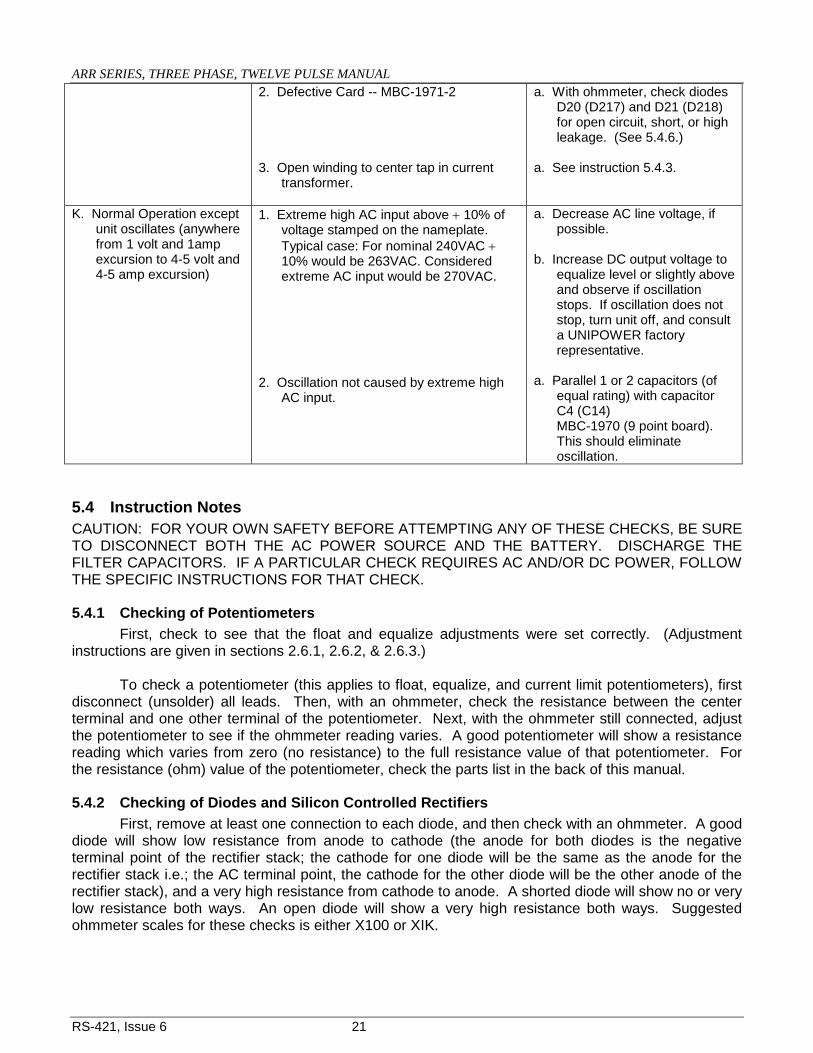
2. Defective Card -- MBC-1971-2 3. Open winding to center tap in current
transformer.
a. With ohmmeter, check diodes D20 (D217) and D21 (D218) for open circuit, short, or high leakage. (See 5.4.6.)
a. See instruction 5.4.3.
K. Normal Operation except unit oscillates (anywhere from 1 volt and 1amp excursion to 4-5 volt and 4-5 amp excursion)
1. Extreme high AC input above + 10% of voltage stamped on the nameplate. Typical case: For nominal 240VAC + 10% would be 263VAC. Considered extreme AC input would be 270VAC.
2. Oscillation not caused by extreme high
AC input.
a. Decrease AC line voltage, if possible.
b. Increase DC output voltage to
equalize level or slightly above and observe if oscillation stops. If oscillation does not stop, turn unit off, and consult a UNIPOWER factory representative.
a. Parallel 1 or 2 capacitors (of
equal rating) with capacitor C4 (C14) MBC-1970 (9 point board). This should eliminate oscillation.
5.4 Instruction Notes CAUTION: FOR YOUR OWN SAFETY BEFORE ATTEMPTING ANY OF THESE CHECKS, BE SURE TO DISCONNECT BOTH THE AC POWER SOURCE AND THE BATTERY. DISCHARGE THE FILTER CAPACITORS. IF A PARTICULAR CHECK REQUIRES AC AND/OR DC POWER, FOLLOW THE SPECIFIC INSTRUCTIONS FOR THAT CHECK.
5.4.1 Checking of Potentiometers First, check to see that the float and equalize adjustments were set correctly. (Adjustment instructions are given in sections 2.6.1, 2.6.2, & 2.6.3.) To check a potentiometer (this applies to float, equalize, and current limit potentiometers), first disconnect (unsolder) all leads. Then, with an ohmmeter, check the resistance between the center terminal and one other terminal of the potentiometer. Next, with the ohmmeter still connected, adjust the potentiometer to see if the ohmmeter reading varies. A good potentiometer will show a resistance reading which varies from zero (no resistance) to the full resistance value of that potentiometer. For the resistance (ohm) value of the potentiometer, check the parts list in the back of this manual.
5.4.2 Checking of Diodes and Silicon Controlled Rectifiers First, remove at least one connection to each diode, and then check with an ohmmeter. A good diode will show low resistance from anode to cathode (the anode for both diodes is the negative terminal point of the rectifier stack; the cathode for one diode will be the same as the anode for the rectifier stack i.e.; the AC terminal point, the cathode for the other diode will be the other anode of the rectifier stack), and a very high resistance from cathode to anode. A shorted diode will show no or very low resistance both ways. An open diode will show a very high resistance both ways. Suggested ohmmeter scales for these checks is either X100 or XIK.

ARR SERIES, THREE PHASE, TWELVE PULSE MANUAL
RS-421, Issue 6 22
Check the silicon controlled rectifiers (SCR’s) for shorts in the same manner in which the diodes are checked (in the silicon controlled rectifiers; the anodes for each rectifier are the anodes of the stack, i.e. the anodes for the SCR’s are the same as the cathodes of the diodes; the cathodes for both SCR’s is the positive terminal point of the rectifier stack). However, a high resistance reading both ways does not necessarily mean the SCR’s are open. To check for open SCR’s de-energize the charger and pull the printed circuit boards out. Connect a 100 ohm resistor from the anode to the gate (located on the terminal board, on the positive side of the rectifier stack, refer to the drawing) of one SCR and turn the charger on. If the rectifier is good, the charger will produce output current. Repeat this procedure for the other SCR. To check for resistance of each gate to cathode of SCR’s use X10 scale. Should read from 70 to 200 ohms in forward and reverse directions. An open or shorted gate will read same as open or shorted diode. Replacement of Silicon Controlled Rectifier, Silicon Diodes, and entire Silicon Rectifier Assembly. A. If it is found that one or more of the diodes and/or the SCR’s is/are defective the following procedure may be used for replacing the defective pieces. Refer to the diagram and drawing to locate the connection points on the charger.
1. Disconnect the charger completely from the AC power and the batteries (DC power). 2. Disconnect the external leads of the rectifier stack and the following points: the positive
and negative terminal points of the stack, the anodes of the rectifier, and the gates of the rectifier (refer to the diagram for the exact location).
3. Loosen the hardware used for mounting the stack to the back panel and remove the
rectifier stack from the cabinet.
4. Remove the defective diode (s) for the defective SCR (s) by: a. disconnecting the diode or rectifier connections where necessary on the rectifier stack. b. Defective pieces may now be removed.
5. To replace the defective parts simply reverse steps one through four. CAUTION: When replacing the defective part, avoid excessive pressure, which may
damage either the case or threads. B. A complete rectifier assembly may be ordered, if you do not wish to replace individual parts. When installing a new rectifier stack, observe the correct polarities.
5.4.3 Checking the Current Transformer First make sure all the leads and cables connected to the current transformer are making good contact. If the connections are good, then disconnect the leads to terminals 1 and 3 (the terminals are marked on the transformer itself), and with an ohmmeter check the resistance between terminals 1 and 2. You should get a reading of 150 ohms ±15%. Next, check the resistance between terminals 2 and 3; the reading here should be approximately 50 ohms above the reading at terminals 1 and 2. If these readings are not obtained, the current transformer is defective and should be replaced.
ARR SERIES, THREE PHASE, TWELVE PULSE MANUAL
RS-421, Issue 6 23
Check also for shorts between the coils, and from the coils to the ground (cabinet is the ground).
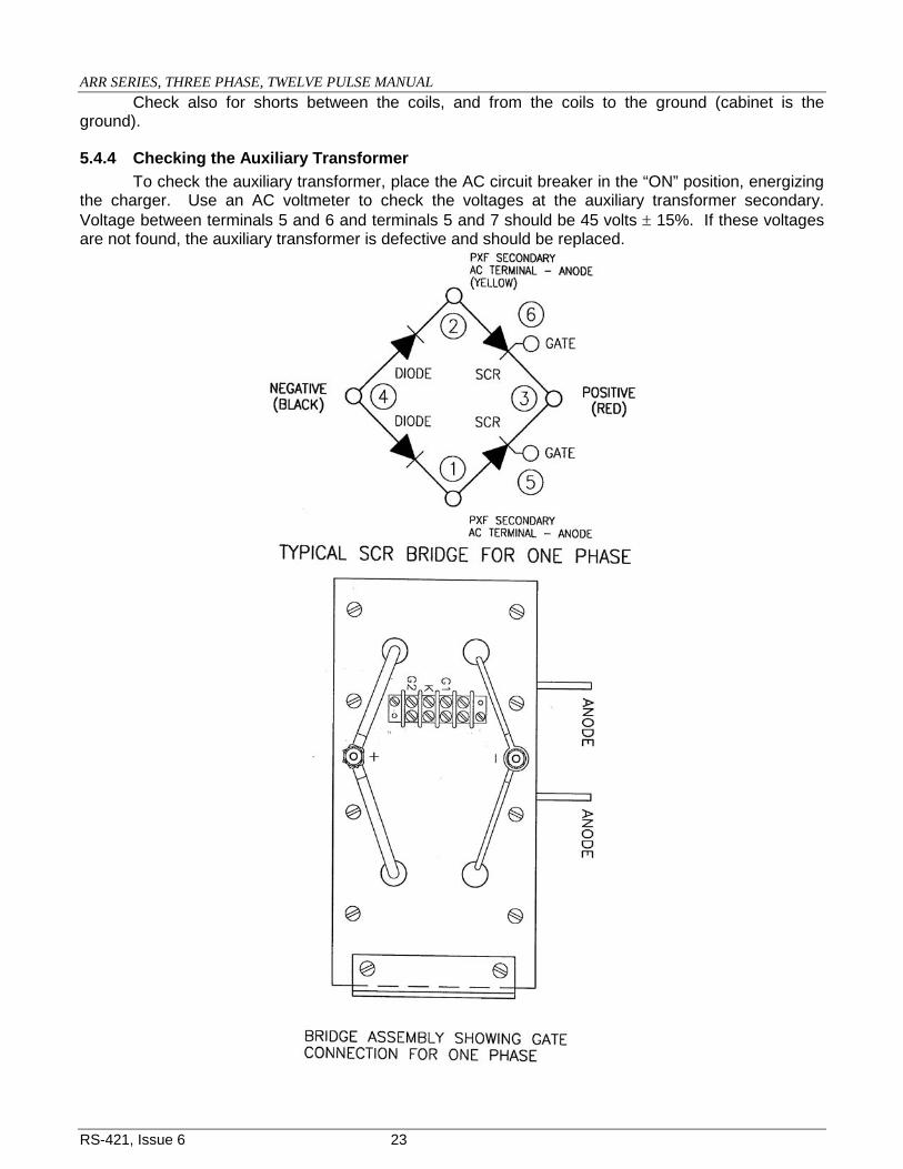
5.4.4 Checking the Auxiliary Transformer To check the auxiliary transformer, place the AC circuit breaker in the “ON” position, energizing the charger. Use an AC voltmeter to check the voltages at the auxiliary transformer secondary. Voltage between terminals 5 and 6 and terminals 5 and 7 should be 45 volts ± 15%. If these voltages are not found, the auxiliary transformer is defective and should be replaced.

ARR SERIES, THREE PHASE, TWELVE PULSE MANUAL
RS-421, Issue 6 24
CAUTION: Connect voltmeter probes before placing the AC breaker in the “ON” position.
5.4.5 Checking DC Filter Capacitors Capacitor trouble can be spotted by a ruptured or broken can. Open capacitors will look normal, however. To check capacitors, first, open the AC circuit breaker and disconnect the battery from the charger. All capacitors in the charger will then bleed to zero voltage or discharge with switch. Second, isolate the capacitor to be tested and apply the test probes of an ohmmeter to the capacitor terminals. If the capacitor is good, it will show a defection to zero resistance, then a steady increase toward infinite resistance. If, however, the capacitor is shorted, it will show zero resistance. If the capacitor is open it will read infinite resistance. Replace faulty capacitors with ones, which have the same rating as the original. See parts list. Filter capacitors are connected in parallel and correct polarities must be observed. When connecting a filter capacitor, if the red dot on the terminal end of the capacitor is to be right of center, the positive (+) terminal connection will be on the bottom. If the red dot is to the left of center, the positive terminal connection will be on the top.
5.4.6 Checking of Printed Circuit Control Cards Before taking the printed circuit cards from the charger, open AC & DC breakers. Carefully lift the card away from its plastic standoff then work the card from the connector. There are two printed circuit cards used for the control circuitry of the charger. A nine-point board and eighteen point board. The following should be checked on the printed circuit boards:
1. All transistors should be checked with an ohmmeter, if found defective, replace with equivalent transistor.
2. All diodes with an ohmmeter. 3. All zeners with an ohmmeter. 4. All resistors with an ohmmeter. 5. All capacitors with an ohmmeter.
6. The saturable reactors and pulse transformer also should be checked with an ohmmeter.
7. Check to see that circuit card fit firmly into the connector. If not, the tabs may be making poor contact. It might help to push the tabs together with a screwdriver.

ARR SERIES, THREE PHASE, TWELVE PULSE MANUAL
RS-421, Issue 6 25
Replace all components, which are found to be defective. Refer to parts list in section 6. If you do not wish to check the circuit boards, replace the entire board and return the defective one to the factory. NOTE: Ohmmeter checks for Printed Circuit Card Components. A. Transistors To check a transistor it must be removed from the circuit board. A good transistor will show some resistance one way and infinite resistance the other way, when the test probes of the ohmmeter (use scale X100) are applied from the base to the emitter and from the base to the collector of the transistor. (The base is the middle prong of the transistor, while the emitter is the prong closest to the notch on the side of the transistor, and the collector is the remaining prong, directly opposite the emitter.) A shorted transistor will read no resistance both ways between the base and the collector, and the collector and the emitter of the transistor. An open transistor will read infinite resistance both ways between the base and the emitter, and the base and the collector. If any transistors are found to be defective replace with equivalent transistors. B. Diodes Before the diodes can be checked the transistors must be removed from the circuit cards. The diodes can then be checked without removing them from the printed circuit cards. (An exception to this rule is the diode across the pulse trans. on the 18-pt. bd.). This diode should have at least one side disconnected, i.e. unsoldered, from the circuit card in order to be checked. A good diode will read some resistance one way and infinite resistance the other way when the test probes of the ohmmeter (use scale X1000) are applied. A shorted diode will read no resistance both ways. An open diode will read infinite resistance both ways. A high leakage diode (this kind should also be changed) will read approximately same resistance in both directions. C. Zeners Before the zeners can be checked the transistors must be removed from the printed circuit cards. If the zener is good, it will show some resistance one way and infinite resistance the other way when the test prods of the ohmmeter (use scale X1000) are applied. A shorted zener will read no resistance both ways. An open zener will read infinite resistance both ways. D. Resistors To check a resistor, first refer to the parts list in order to find the correct resistance value. Then set your ohm scale accordingly. A good resistor will give the correct reading both ways, when the test probes are applied. A shorted resistor will read no resistance both ways. An open resistor will read infinite resistance both ways. Replace a defective resistor with one of the same rating. See parts list in section 6.. E. Capacitors To check a capacitor apply the ohmmeter probes to the capacitor terminals. If the capacitor is good it will show a deflection to the zero resistance (this is caused by the battery of the ohmmeter charging the capacitor), then a steady increase toward infinite resistance. If the capacitor is shorted, it
ARR SERIES, THREE PHASE, TWELVE PULSE MANUAL
RS-421, Issue 6 26
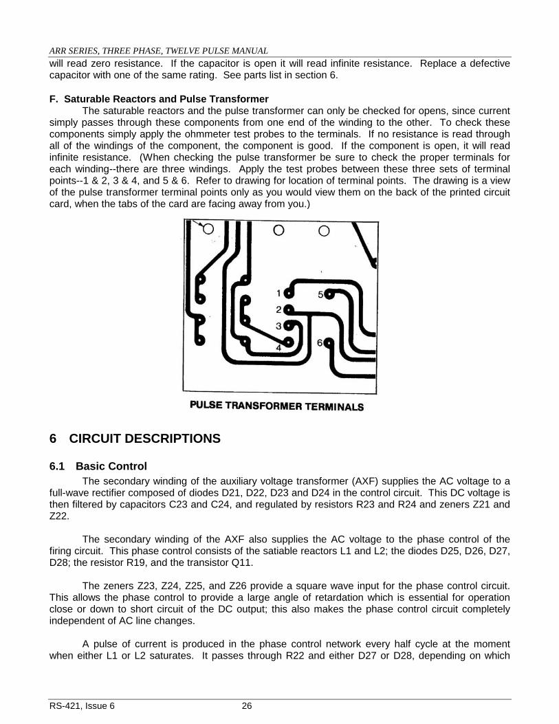
will read zero resistance. If the capacitor is open it will read infinite resistance. Replace a defective capacitor with one of the same rating. See parts list in section 6. F. Saturable Reactors and Pulse Transformer The saturable reactors and the pulse transformer can only be checked for opens, since current simply passes through these components from one end of the winding to the other. To check these components simply apply the ohmmeter test probes to the terminals. If no resistance is read through all of the windings of the component, the component is good. If the component is open, it will read infinite resistance. (When checking the pulse transformer be sure to check the proper terminals for each winding--there are three windings. Apply the test probes between these three sets of terminal points--1 & 2, 3 & 4, and 5 & 6. Refer to drawing for location of terminal points. The drawing is a view of the pulse transformer terminal points only as you would view them on the back of the printed circuit card, when the tabs of the card are facing away from you.)
6 CIRCUIT DESCRIPTIONS
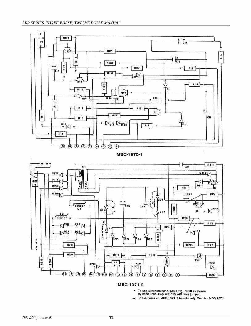
6.1 Basic Control The secondary winding of the auxiliary voltage transformer (AXF) supplies the AC voltage to a full-wave rectifier composed of diodes D21, D22, D23 and D24 in the control circuit. This DC voltage is then filtered by capacitors C23 and C24, and regulated by resistors R23 and R24 and zeners Z21 and Z22. The secondary winding of the AXF also supplies the AC voltage to the phase control of the firing circuit. This phase control consists of the satiable reactors L1 and L2; the diodes D25, D26, D27, D28; the resistor R19, and the transistor Q11. The zeners Z23, Z24, Z25, and Z26 provide a square wave input for the phase control circuit. This allows the phase control to provide a large angle of retardation which is essential for operation close or down to short circuit of the DC output; this also makes the phase control circuit completely independent of AC line changes. A pulse of current is produced in the phase control network every half cycle at the moment when either L1 or L2 saturates. It passes through R22 and either D27 or D28, depending on which
ARR SERIES, THREE PHASE, TWELVE PULSE MANUAL
RS-421, Issue 6 27
reactor saturates. The voltage drop that this current produces across R22 makes the junction of R25 and R214 more negative. This turns transistor Q21 off. When transistor Q21 turns off it causes transistor Q22 to turn on. This allows capacitor C21 to discharge producing a fast rising pulse in the primary of the pulse transformer applied to the gates of the silicon-controlled rectifiers (SCR). The SCR that is forward biased is turned on by this pulse. When one saturable reactor is conducting, the other is being reset. The reset current path consists of diode D25 or D26, the control transistor Q11 and the secondary winding of the AXF. The amount of reset current determines when the reactor being set will saturate in the next half-cycle. More reset current will result in later saturation in the next half-cycle. This means the SCR will also turn on later, which means reduced charger output. Less reset current thus produces more charger output. The amount of reset current is determined by the signal fed into the base of Q11. This signal is derived from a network, which senses any changes in the output voltage of charger. This network is composed of a voltage divider, a reference zener, and a differential amplifier. The voltage divider consists of resistor R12 and the float-equalize adjustment potentiometers. This divider is directly across the output of the charger. The differential amplifier consists of transistors Q12, Q13; resistors R13, R14, R111, R115 and R116; and zener Z11. The voltage across R12 is proportional to the output voltage and is set by adjustment of the float potentiometer to equal the zener voltage of Z11. This balances the voltages at the bases of Q12 and Q13 so that the current in each of the collectors is approximately equal. When the charger output voltage decreases the voltage across R12 drops. Q13 is then turned on more. This causes Q12 to turn off so that the sum of the currents through R115 remains essentially what it was when the amplifier was balanced. When Q13 turns on the potential at its collector is lowered. This turns off Q11 and results in less reset current in the reactors. Hence the SCR’s are fired sooner which allows more current output from the charger. This, of course, tends to maintain constant charger voltage output. The opposite reaction occurs when the output voltage increases, that is, Q13 is turned off. This turns Q11 full on and results in decreasing charger output. The current limit resistor (RCL) provides a constant load for the CT also limits the current limit adjustment range.

ARR SERIES, THREE PHASE, TWELVE PULSE MANUAL
RS-421, Issue 6 28
CONTROL BOARD PARTS LIST
Note: Items on Board #1 and #2 are denoted by preceding the component number with a 1 or 2. (Example: Q11 is on board #1: Q21 is on board #2.)
Identifying # MBC-1970-1
(“A” Board) UNIPOWER Part No. Identifying # MBC-1971-2
(“B” Board) UNIPOWER Part No.
Q11, 12, 13 Transistor, 2N2219A, NPN JS00407 Q21, 22 Transistor, 2N2219A, NPN JS00407
Q14 Transistor, MPSL51, NPN JS00462 D21 to 218 Diode , 1 A, 400 PIV, 1N4004 JS00500
Z11 Zener, ¼ W, 6.8 V, 1N957B JS00317 Z21 Diode, Zener,
18V, 5%, 5W JS00762
D10, 11, 12, 13
Diode , 1 A, 400 PIV, 1N4004 JS00500 Z22
Diode, Zener, 20V, 5%, 1N5357B
JS00444
D14 Diode, Signal, 1N914 JS00499 Z23, 24, 25, & 26 Diode, Zener, AC, 500 mW, 13V, 1N5243B
JS00473
R118 Resistor, 10k Ohm, ½ W, 10% JE00111 R21 Resistor, 1k Ohm,
½ W, 10% JE00102
R119 Resistor, 5.6k Ohm, ½ W, 10% JE00115 R22 Resistor, 681
Ohm, ½ W, 1% JE00101
R12, 112 Resistor, 681 Ohm, ½ W, 1% JE00101 R23 Resistor, 1k Ohm,
5W, 5% JE00208
R13 Resistor, 1k Ohm, ½ W, 10% JE00102 R24 Resistor, 510
Ohm, 5W, 5% JE00186
R14 Resistor, 33k Ohm, ½ W, 10% JE00109 R25 Resistor, 33k
Ohm, ½ W, 10% JE00109
R15 Resistor, 390 Ohm, ½ W, 10% JE00116 R26 Resistor, 330k
Ohm, ½ W, 10% JE00463
R16 Resistor, 4.7k Ohm, ½ W, 10% JE00114 R27 Resistor, 10k
Ohm, ½ W, 10% JE00111
R17, 18 Resistor, 221k Ohm, ½ W, 1% JE00209 R28,29,210 Resistor, 2.2k
Ohm, ½ W, 10% JE00105
R19 Resistor, 100 Ohm, ½ W, 10% JE00113 R221 Resistor, 1.5k
Ohm, ½ W, 1% JE00108
R110 Resistor, 4.75k Ohm, ½ W, 1% JE00097 R212, 213 Resistor, 6.81k
Ohm, ½ W, 10% JE00104
R11, 111, 116 Resistor, 12.1k Ohm, ½ W, 1% JE00096 R214 Resistor, 6.81k
Ohm, ½ W, 1% JE00095
R113, 114 Resistor, 6.81k Ohm, ½ W, 1% JE00095 R215, 216 Resistor, 22 Ohm,
½ W, 10% JE00112
R115 Resistor, 1.5k Ohm, ½ W, 1% JE00099 R217, 218 Resistor, 100
Ohm, ½ W, 10% JE00113
R117 Resistor, 1.00k Ohm, ½ W, 1% JE00098 C21 Cap. Electrolytic,
1µF 50 Vdc JC00064
R120 Resistor, 2.7k Ohm, ½ W, 10% JE00106 C22
Cap.Ceramic Disk, 0.02µF 1000 Vdc
JC00052
P-1 Pot. - Cur. Lim. 10k Ohm, 1 W JE00206 C23, 24 Cap. Electrolytic,
100µF 100 Vdc JC00071
C11,12,13 Cap. Electrolytic, 100µF 100 Vdc JC00071 XFI
Pulse Transformer, UNIPOWER
JT00156
C14 Cap. Tantalytic, Non-polarized,22µF,25V min. JC00074 L1, L2
Saturable Reactor Assembly, UNIPOWER
JT00279
C15 Cap. Tantalytic, Non-polarized, 10µF, 15 Vdc JC00066 RBP
Pot. - Reactor Balance 1k Ohm, 1 W, 20 Turn
JE00223

ARR SERIES, THREE PHASE, TWELVE PULSE MANUAL
RS-421, Issue 6 29
CONTROL BOARD “A”
MBC01970-1
CONTROL BOARD “B”
MBC01971-2
ARR SERIES, THREE PHASE, TWELVE PULSE MANUAL
RS-421, Issue 6 30

ARR SERIES, THREE PHASE, TWELVE PULSE MANUAL
RS-421, Issue 6 31
The current limit circuit consists of diodes D10, 12 & 13, resistors R11, 14, & 16, potentiometer P1. The voltage developed by the CT is applied at D13. When of sufficient value, it reverse biases D13 and conducts through D12 to increase the base voltage level of Q11. When this level is above that applied through D11 from the feedback source, Q11 is turned on harder to increase the reactor reset current, which results in reduced output. The “Soft-Start” circuit consists of capacitors C11 & 14, diode D14, resistors R112, 114, 119, & 120, and transistor Q14. On turn-on, C14 is instantly charged to full voltage. This decreases the base voltage of Q13, which turns off and increases the base voltage of Q11. Q11 then conducts full reset current to retard SCR firing. Since C11 charges from the same source, the gradual build-up of its voltage turns on Q14. When Q14 conducts, it reverse biases D14 which allows the base voltage of Q13 to be established at the level determined by feedback through R111. One very important feature is provided by the use of R112 and C14, which are connected, from the collector to the base of Q13. This is sometimes called a snubber or anti-hunt circuit and is a useful method of eliminating oscillation. With this so-called snubber it is possible to operate the charger as a battery eliminator without making any modifications, either to the power or control circuit.
7 ACCESSORIES AND OPTIONAL EQUIPMENT
1. One hundred millivolt filtering reduces the AC ripple voltage. 2. Voltage alarms sense and signal low and high DC voltages in the charger and the
batteries. 3. Ground detection lights and switches in various combinations provide for the sensing for
grounds in the system. 4. Equalize timers replace the float-equalize switch and can provide for equalize time from 0
hours to 255 hours. 5. Load sharing allows two or more chargers to be used on the same load with each charger
having the same load. Panel-mounted controls are optional. 6. A blocking diode can be provided in the DC output to allow individual sensing of faults in
chargers operating in parallel. 7. Pilot lights indicate when the charger is in equalize operation, or when the charger has a
DC output or no output. 8. 50 Cycle operation allows the charger to be used in areas where this is necessary. 9. Lightning arrestors provide protection from surges on the line created by lightning. 10. No charge alarm signals on low DC current rather than low DC voltage. 11. Voltmeter switches in various combinations provide for the reading of both load and
charger voltages utilizing the chargers voltmeter.

ARR SERIES, THREE PHASE, TWELVE PULSE MANUAL
RS-421, Issue 6 32
INTERPHASE “C” BOARD
MBC-1951 PARTS LIST
Component Identification
Component Description
UNIPOWER Part No.
C1 Capacitor, 10 uF, 100 V,
Aluminum electrolytic JC00069
CR1-CR8 Diode, silicon 1A, 400 V, 1N4004
JS00500
P1 Potentiometer, 200 ohm, ½ watt, 1 turn
JE00169