artificial photosynthesis. synthesis and characterisation
TRANSCRIPT

Artificial Photosynthesis. Synthesis and characterisation of
complexes containing phenoltriazole ligands.
by
Benedicte Evrard.
A Thesis presented to Dublin City University for the degree of Masters ofSciences.
Supervisor Professor Johannes G. Vos.
School of Chemical Sciences.Dublin City University.
March 2000.

Acknowledgements
I w ould like to thank m ost o f all Professor Han V os w ho offered m e his guidance for the past two years. H is patience and great support during the writing up part especially were very helpful and appreciated.A very special thanks to Tia K eyes who explained all about it to m e, from the experimental side o f things to the more theoretical aspects, such as the interpretation o f results.Thank you to all m y labmates for their continual support and the friendly athmosphere in the lab. They were always there to help w hen things felt unclear or wrong.Thanks to the technicians for obvious reasons and to anybody from the chemistry department who helped in any way.I am very grateful to the B ologna research group for w elcom ing m e so kindly there, allow ing m e to learn a lot from observing their work in the laboratory.Thanks to Conan and Tony for the computer end o f it.A nd finally I w ould like to thank the EU-TM R programme for the financial support.

I hereby certify that this material, which I now submit for assessm ent on the programme o f study leading to the award o f Masters o f Sciences is entirely m y own work and has not been taken from the work o f others save and to the extent that such work has been cited and acknowledged within the text o f m y work.
ID No: _ _ 3 2 î l û 0 O
Date: 1 0 - ( f t - 2.COO
Table of contents
Chapter 1: Scope o f the thesis. 1.Chapter 2: Theory o f artificial photosynthesis. 2.
2.1. Mimicking photosynthesis: general principles. 2.2.2. Electron and energy transfer processes, description o f the
PMD and its various components. 6.2.2.1. Supramolecular species. 6.2.2.2. Electronic interaction in polynuclear complexes. 8.2.2.3. Energy and electron transfer processes. 10.2.2.4. Design o f multicomponent systems. 16.2.2.5. Energy levels o f transition metal complexes. 21.2.2.6. Synthesic aspects. 23.
2.2.7. General behaviour o f polypyridine transition metal complexes. 25.2.3. The artificial leaf. 26.
Chapter 3: Synthesis and characterisation o f phenol-containing ruthenieumpolypyridyl complexes. 30.
3.1. Introduction. 30.3.1.1. Decanuclear complex in which the excitation energy can be
channelled in the desired direction. 30.3.1.2. Tetranuclear complex containing both an electron-rich and
electron-poor ligand. 34.3.1.3. Complexes containing a tris(bpy) tripod ligand. 37.3.1.4. Rigid rod-like dyads usingpolyphenylene spacers. 38.3.1.5. Ru polypyridine complexes entrapped in zeolite supercages. 41.3.1.6. Conclusion. 42.
3.2. Experimental part. 45.3.2.1. Synthesis. 45.3.2.2. Analytical HPLC. 50.3.2.3. Nuclear magnetic resonance. 50.
iv
3.2.4. Acid/base titrations. 50.3.2.5. Electrochemistry. 51.3.2.6. Spectroelectrochemistry. 51.3.2.7. Absorption/ emission meausrements. 52.3.2.8. Luminescent lifetime measurements. 52.3.2.9. Hyperchem. 52.
3.3. Results and discussion. 53.3.4. Mononuclear complexes. 56.
3.4.1. Synthesis. 56.3.4.2. Structural characterisation. 56.3.4.3. Absorption and emission properties. 64.3.4.4. Acid/base behaviour. 66.3.4.5. Redox properties. 76.3.4.6. Spectroelectrochemistry. 80.3.4.7. Conclusion. 82.
3.5. Dinuclear complexes. 83.3.5.1. General. 83.3.5.2. Synthesis and structural characterisation. 84.3.5.3. Absorption and emission properties. 90.3.5.4. Electrochemistry. 93.3.5.5. Conclusion. 96.
Chapter 4: Summary and suggestions for future work. 97.
V
Abstract.
This project describes the synthesis and study o f the electrochem ical and photophysical properties o f four ruthenium(bipyridyl)2 com plexes containing a triazole ring and a phenol grouping, w ith respect to artificial photosynthesis.A concerted effort has been made in the last decades to create com pounds capable o f absorbing the solar light and converting it into a stable chem ical form. This project deals w ith photoinduced electron transfer.Ruthenium polypyridyl com plexes have been show n to be attractive candidates for excited state electron transfer process in fluid solution. Two different phenoltriazole ligands have been synthesised for their interesting features. A ltering the state o f protonation o f the triazole ring affects the photophysical behaviour o f the com plexes. The phenol m oiety is used in an attempt to. m im ic the tyrosine function in photosystem II where this grouping is involved in photoinduced electron transfer to P 680. One o f the ligands synthesised contains a pyridyl ring, the other one contains a pyrazyl ring. This difference has a significant effect on the photophysics o f the com plexes.Acid/base behaviour, electrochemistry and absorption/em ission properties o f the com plexes have been studied and compared w ith those o f appropriate m odel compounds. The results are discussed in order to understand the photophysical and electrochem ical behaviours o f these com pounds, w ith the final goal o f designing photochem ical m olecular devices.

Chapter 1: Scope o f the thesis.
The input o f solar energy to the Earth is huge compared w ith our needs4. Solar energy is a great potential natural resource, having the advantages o f being non-polluting and renewable. That is w hy a concerted effort has been m ade in the last decades to determine a means o f collecting it. That m ay be done by creating com pounds capable o f absorbing the solar light and converting it into a stable chem ical form, in other words, by designing a multicom ponent system capable o f interacting with light to perform a useful light induced function. Such a system is called a photochem ical m olecular device (PM D). This energy conversion m ay occur by two different processes: energy transfer or charge separation. Earlier studies have shown that poplypyridyl polynuclear com plexes o f Ruthenium(II) and Osmium(II) show interesting properties regarding those two processes.4, 5 This project deals w ith charge separation and describes the synthesis and properties o f four ruthenium-polypyridyl com pounds prom ising for solar energy conversion. Tw o ligands H2LI and H2L2 (represented hereunder), their mononuclear and dinuclear com plexes have been synthesised and investigated.
1. P *H2L2
The ligand H2L2 contains a pyrazine ring whereas H2LI contains a pyridine ring. This difference leads to variations in the photophysical behaviour o f the com plexes, a comparison is presented. Triazole ligands have the advantage o f being photostable, w hile containing a broad range visible absorbance.60 A lso, the bridging triazole in such com plexes is anionic w hich facilitates good electron com m unication betw een the two metal centres.37 Additionally the photophysical properties o f com plexes w ith such ligands can be tuned by varying the degree o f protonation o f the triazole ring.50 The phenol m oiety can be used to m im ic the tyrosine function in photosystem II where this grouping is involved in photoinduced electron transfer to P 68038.The aim o f this thesis is to produce som e m odel com pounds w hich can be used to investigate the interaction between a light absorber and an electrodonor like phenol.
1

Chapter 2: Theory o f artificial photosynthesis.
2.1. Mimicking photosynthesis: general principles.Light induced functions take place in nature during processes such as photosynthesis and vision. So examination o f natural PM D's (such as the chloroplast in photosynthesis) show s the fundamental principles underlying the light energy conversion process52. The conversion o f light energy into chem ical energy in the photo synthetic process is based on two types o f PMD's: (i) light harvesting antenna devices, w hich are made o f hundreds o f pigm ents able to absorb the solar light and convey it to a com m on acceptor (reaction centre), (ii) reaction centre where the excitation energy is used to perform a charge separation process which converts the electronic energy into chem ical energy. Therefore solar energy conversion m ay be achieved through m im icking the unit function o f photosynthesis, where the chlorophyll photosensitiser is capable o f light absorption over a w ide visible spectrum range ultim ately leading to a long-lived charge separation state. The follow ing equation is a sim plistic definition o f photosynthesis1:
6 CO2 + 6 H2O —> C6Hi2C>6 + 6 O2 (Equ. 2.1)
So green plants use a certain amount o f the sunlight for their source o f energy and convert it into chem ical energy in the form o f carbohydrates via the process o f photosynthesis. Photosynthesis occurs in tw o discrete phases:1. Light reactions, in w hich the overall reaction is the photoinduced splitting o f water to form gaseous oxygen with the concurrent transfer o f electrons and protons to other m olecules generating energy rich ATP (adenosine trinucleotide phosphate) and biological reducing agent N A D PH (nicotinam ideadenine dinucleotide phosphate).
2 H20 0 2 + 4 e + 4H+ (Equ. 2.2)
2
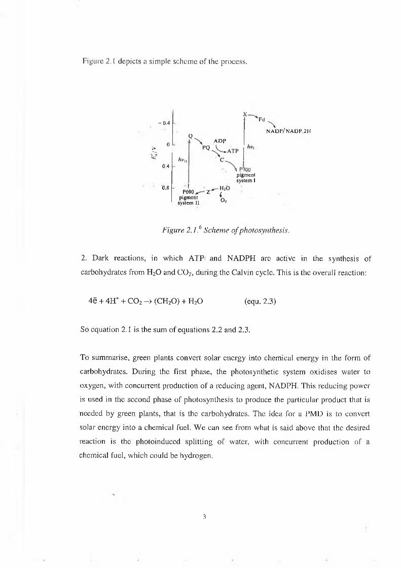
Figure 2.1 depicts a s im ple sch em e o f the process.
x- 0 .4 Fd
NAD P/NA D P.2HQ ADP0>
0,4 \ P700 pigment system I0.8
pigment system IIP690
~ Z < o2
Figure 2.1.6 Scheme of photosynthesis.
2. Dark reactions, in which ATP and NADPH are active in the synthesis of carbohydrates from H20 and CO2, during the Calvin cycle. This is the overall reaction:
So equation 2.1 is the sum of equations 2.2 and 2.3.
To summarise, green plants convert solar energy into chemical energy in the form of carbohydrates. During the first phase, the photosynthetic system oxidises water to oxygen, with concurrent production of a reducing agent, NADPH. This reducing power is used in the second phase of photosynthesis to produce the particular product that is needed by green plants, that is the carbohydrates. The idea for a PMD is to convert solar energy into a chemical fuel. We can see from what is said above that the desired reaction is the photoinduced splitting of water, with concurrent production of a chemical fuel, which could be hydrogen.
4ë + 4H+ + C 02 -> (CH2O) + H2O (equ. 2.3)
3

B asically w e want to design assem blies capable o f efficient light induced charge separation leading to the photocleavage o f water into O2 and energy rich H2, fo llow ing this schem e2:
S - > S *S* -> S+ + R-2R ’ + H20 -> 2R + H2 + 2 0 H ' 4S + 2H20 4S + H2 + 4H+
The primary step is the photoexcitation o f the sensitiser, as in photosynthesis. The excited state is then quenched by electron transfer to a relay o f acceptors in a charge separation process. The relay then passes the electron to a suitable catalyst capable o f decom position o f water. The final step involves actual decom position o f water.Som e points2 are important to the success o f the potential PMD:1. The photosensitiser should possess a broad range o f visib le absorbance (corresponding to the solar spectrum), the correct redox properties in the excited state and it should be photostable.2. The PM D should perform an efficient electron transfer leading to a stable charge separated state.3. Continual "dark" reactions leading to the decom position o f water should occur, as w ell as continuous renewal o f both sensitiser and relay (quenching) m olecules to their original oxidation states.A s m entioned above an important step in the photocleavage o f water is the creation o f a long-lived charge separated state. This can be done b y creating a charge separation over a long distance. I f there is a sensitiser linked to a series o f relay species, i.e. a series o f electron acceptors along a redox gradient, w e can initially photoexcite an electron o f the sensitiser, w hich w ill be vectorially transferred to the ultimate acceptor. The forward electron transfer reaction should be faster than the back electron transfer reaction at each step. This process is represented in figure 2.2.
4

Figure 2.2/ Representation o f a photosensitiser linked to a series o f relay species.
The first approach to mimic photosynthesis is the creation of "biomimetic" species which involve molecular assemblies of structure reminiscent of that found in nature, such as porphyrins, quinones.' This project deals with the second approach, which is to create "abiotic" assemblies. The most successful class of such compounds has been ruthenium-polypyridine chrom ophores, and it still attracts great interest because of its advantageous photophysical and electrochemical properties (as will be explained in the part 3.3). A suitable choice of the building blocks (e.g. concerning the photophysical, photochemical and electrochemical properties) and of the bridging ligand (which provide the electronic coupling between these building blocks) assembled in an appropriate supramolecular array, can allow the occurrence of very useful light induced functions such as energy migration and/or charge separation.
The next part will introduce the concepts o f energy and electron transfer processes. It also describes the different entities of a PMD and gives the general features of the polypyridine ruthenium and osmium complexes.
5

2.2. Energy and electron transfer processes, description of the PMD and its components.4'5In order to develop a PM D, it is necessary to understand the electron and energy transfer processes and the effect o f every com ponent o f the assem bly on these processes. With a thorough understanding o f the interaction betw een components and effect that the various components can have on the functioning o f the system , it is possible to develop a supramolecular assem bly in w hich every com ponent is carefully chosen and has its role in the overall functioning o f the PM D. So it is possible to tune the properties o f a supramolecular assem bly by varying the components.In this chapter a summary o f the theoretical aspects necessary to the developm ent o f a PM D is given.
2.2.1. Supramolecular species.
A chem ical species can be described as a single unit (large m olecule) or as made o f distinct com ponents (supramolecule). The distinction betw een the two cases is based on the degree o f interaction between the electronic subsystem s o f the com ponents units.-If this interaction is weak, the system can be v iew ed as a supramolecular species.Light excitation o f a supramolecular species A -B leads to excited states that are substantially localised on A or B , or causes an electronic transfer from A to B (or vice- versa). Similarly, oxidation or reduction o f a supramolecular species can substantially be described as oxidation or reduction o f specific com ponents.-If the interaction is strong, the system is better described as a large m olecule.Light excitation o f a large m olecule leads to excited states that are substantially delocalised on both A and B. Oxidation or reduction o f a large m olecule leads to species where the hole or the electron is substantially delocalised on the entire system (figure 2.3).
6
supramolecularspecies
compound largemolecule
*A ^BA ^*B
A +^B -A '^ B +
— — A-^B ---— --► *(Av>-B)
A '^ B +e- +p-A^ B- -------------- A ^ B ?----- . (A^B)-
A+^ B _e' _e_A ^ B + ------5---------------- 5-► (A^B)+
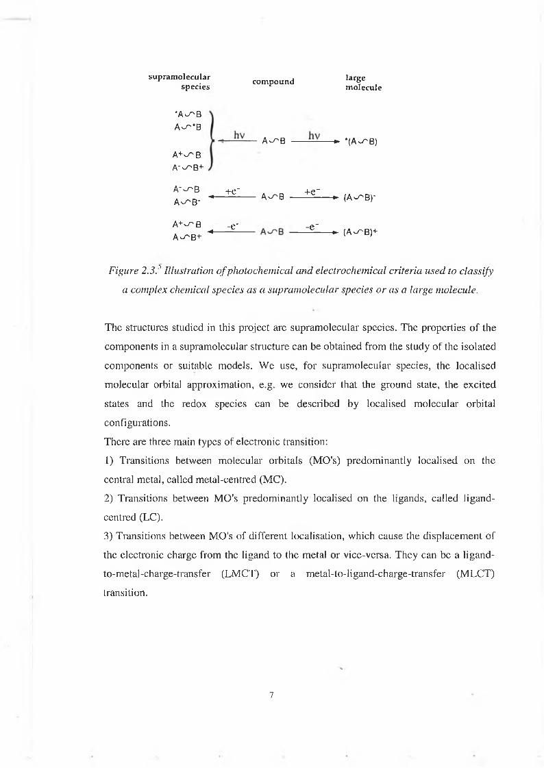
Figure 2.3.'' Illustration o f photochemical and electrochemical criteria used to classify a complex chemical species as a supramolecular species or as a large molecule.
The structures studied in this project are supramolecular species. The properties o f the components in a supramolecular structure can be obtained from the study of the isolated components or suitable models. W e use, for supramolecular species, the localised molecular orbital approximation, e.g. we consider that the ground state, the excited states and the redox species can be described by localised m olecular orbital configurations.There are three main types of electronic transition:1) Transitions between molecular orbitals (MO's) predominantly localised on the central metal, called metal-centred (MC).2) Transitions between MO's predominantly localised on the ligands, called ligand- centred (LC).3) Transitions between MO's of different localisation, which cause the displacem ent of the electronic charge from the ligand to the metal or vice-versa. They can be a ligand- to-metal-charge-transfer (LMCT) or a metal-to-ligand-charge-transfer (MLCT) transition.
7

2.2.2. Electronic interaction in polynuclear complexes.
The bridging ligand plays an important role in determining the interaction between the two metal centres and so in deciding whether the polynuclear complex is better described as a supramolecular species or a large molecule. Depending on its length and electronic structure the bridging ligand can induce a more or less important degree of delocalisation between the components. Let us take the case of a mixed-valence dinuclear complex such as this one:
[Ru(NH3)5-L-Ru(NH3)5]5+
where L is a neutral, symmetrical bridging ligand.According to the magnitude of the electronic coupling (H), there are three cases (see figure 2.4):1) If H is negligible (very long centre-to-centre distance for example), the figure 2.4.a. represents adequately the system at any geometry along the nuclear co-ordinate.There are two valence-localised "electronic isomers", Ru(II)-Ru(III) and Ru(III)-Ru(II). The properties exhibited by the complex shown above are the perfect superposition of the properties of isolated Ru(NH3)5L3+ and Ru(NH3)5L2+ components.At the equilibrium geometry of each electronic isom er the other isomer can be considered an electronically excited state. The energy separation between these states is called reorganisational energy (A,), related to A C/1-0' of Marcus electron transfer theory.At the crossing point both electronic isomers have the same geometry. This is the nuclear configuration where there are no Franck-Condon restriction to electron exchange between the two centres. But even if the system acquires sufficient energy to reach the intersection region, the probability of electron exchange is negligible. This is called class I behaviour. One example of compound belonging to this class is the following:
O 'CH ’» -O
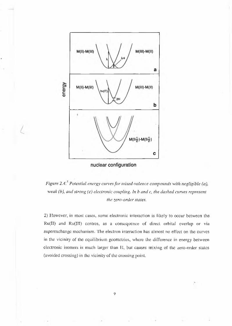
Figure 2.4? Potential energy curves fo r mixed-valence compounds with negligible (a), weak (b), and strong (c) electronic coupling. In b and c, the dashed curves represent
the zero-order states.
2) However, in most cases, some electronic interaction is likely to occur between the Ru(II) and Ru(III) centres, as a consequence of direct orbital overlap or via superexchange mechanism. The electron interaction has almost no effect on the curves in the vicinity of the equilibrium geometries, where the difference in energy between electronic isomers is much larger than H, but causes m ixing of the zero-order states (avoided crossing) in the vicinity o f the crossing point.
9

Systems of this type can still be considered as valence localised and will still exhibit the properties of the isolated components. However, new properties promoted by the R u11- Ru111 interaction can also be observed, such as optical electron transfer.This is called class II behaviour.Example:
3) If the electronic coupling is strong, the dinuclear complex is better considered a fully delocalised Rulll/2-Ru species, with properties that are mostly unrelated to those of the hypothetical Ru(NH 3 )5L3+ and Ru(NH3)5L2+ components.This is called Class III behaviour.
Example: N = C ~ C = N
The arguments concerning the degree of electron delocalisation discussed above for symmetric redox systems are general, and can be extended to systems which exhibit redox asymmetry. The type of compounds we are dealing with in this project (supramolecule), generally belong to the class II.
2.2.3. E nergy and electron transfer processes.
Under light excitation, three phenomena can happen.The light excitation can lead to an excited state of the photosensitiser, which can be then subject to an energy transfer to the quencher or an electron transfer process to the quencher (photoinduced electron transfer).The light excitation can also directly induce an electron transfer process (optical electron transfer).This is illustrated in figure 2.5:
10
nuclear configuration
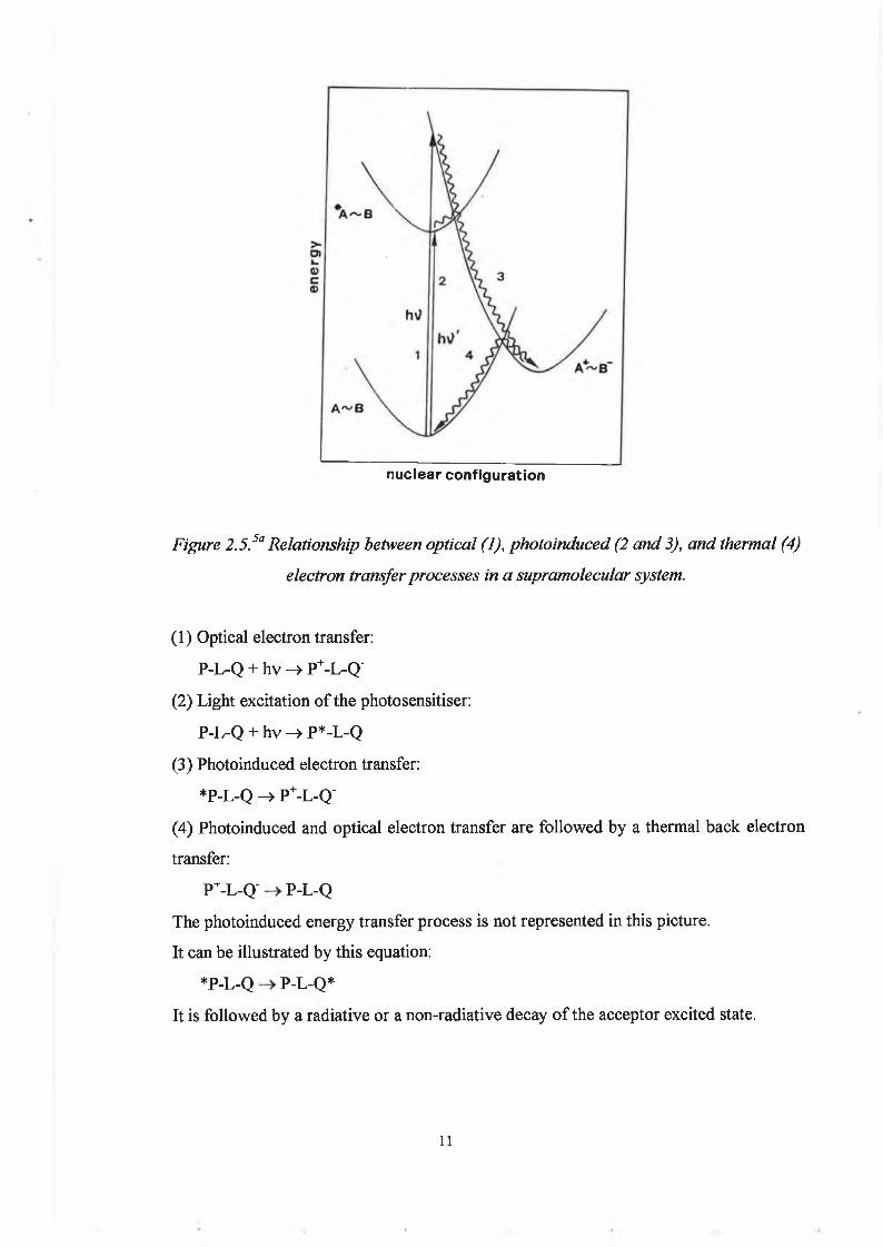
Figure 2.5.5a Relationship between optical (1), photoinduced (2 and 3), and thermal (4) electron transfer processes in a supramolecular system.
(1) Optical electron transfer:P-L-Q + hv —> P+-L-Q'
(2) Light excitation o f the photosensitiser:P-L-Q + hv -> P*-L-Q
(3) Photoinduced electron transfer:*P-L-Q -> P+-L-Q'
(4) Photoinduced and optical electron transfer are fo llow ed by a thermal back electron transfer:
P+-L-Q' P-L-QThe photoinduced energy transfer process is not represented in this picture.It can be illustrated by this equation:
*P-L-Q P-L-Q*It is follow ed by a radiative or a non-radiative decay o f the acceptor excited state.
11

2.2.3.a. Photoinduced electron transfer.
It is well known that light excitation increases both the oxidising and the reducing power of a molecule. Therefore in a multicomponent supramolecular system light excitation can often be followed by an electron transfer process, e.g.:
Photoexcitation: A~B + hv —» *A~BPhotoinduced oxidative electron transfer:
*A~B -> A+~B‘Photoinduced reductive electron transfer:
*A~B A ~B+
The relevant thermodynamic parameters are the reduction potentials of the A+/*A, B/B" and *A/A~, B+/B couples. To a first approximation the reduction potential for the excited state couples may be calculated from the reduction couple of the ground state couples and the one-electron potential corresponding to the zero-zero excitation energy:
E(A+/*A )» E(A+/A) - E°-° (equ. 2.4)E(*A/A') - E(A/A~) + E°‘° (equ. 2.5)
As a consequence feasibility of an excited state electron transfer process can beassessed by means of the well-known W eller equation.
AG° = -E0 0 - E(B/B ')’ + E(A+/A )’ - E ,P (equ. 2.6.)
where AG° is the free energy change of the process, E°'° is the spectroscopic energy of the excited state, E(A+/A )’ and E(B/B")’ are the one-electron energies corresponding to the reduction of the two species, and E|p is the coulombic stabilisation energy of the products.
12

A current theory is the Marcus m odel5b:In an absolute rate formalism the rate o f an electron transfer process depends on the free activation energy (AG5) , the electronic interaction between the donor and acceptor groups (k) and the reorganisational energy (A,), according to this equation:
k = v nk exp (-AG*/RT) A G *=(^/4)(1+(A G 7X ))2 (equ. 2.7.)
where vn is the average nuclear factor, AG° is the standard free energy change o f the reaction.This equation predicts that for a series o f reactions with the same X and k values, a log k vs AG° plot is a bell shaped curve involving three regions.(i) A "normal" region for endoergonic and slightly exoergonic reactions in w hich log k increases w ith increasing driving force,(ii) An activationless maximum for X = -AG°,(iii) An "inverted" region for strongly exoergonic reactions in w hich log k decreases with increasing driving force.The reorganisational energy can be expressed as the sum o f tw o independent contributions:1) The reorganisation o f the "inner" nuclear m ode (bond lengths and angles within the tw o reaction partners).2) The reorganisation o f the "outer" nuclear m ode (solvent reorientation around the reacting pair), w hich is the predominant contribution in polar solvents for electron transfer processes.The transmission coefficient is related to the detailed shape o f the potential energy curves in the intersection region, in other words to the electronic interaction, w hich should decrease exponentially with donor and acceptor distance. D epending on the amount o f electronic interaction there are tw o lim iting cases:(i) I f the electronic interaction H is very small, v « v n , k = ( v / v n ) « 1 and
k = v exp(-AG*/RT). This is the nonadiabatic limit o f electron transfer reactions where the electron transfer at the transition state geometry is the determining step.
13
(ii) I f H is sufficiently high so that v » vn, k = 1 and so k = Vn exp(-AG*/RT).This is the adiabatic limit o f the electron transfer reactions where the nuclear motion that leads to the transition state geometry is the determining step.
It should be noted that the amount o f electronic interaction required to promote an electron transfer process is very small (a few cm '1).There is also a sim ple quantum mechanical treatment which, unlike the classical treatment allows for nuclear tunnelling between reactant and product levels at energies lower than that o f the intersection point.
2.2.3.b. Energy transfer.
Energy transfer processes can occur by tw o mechanisms:(i) The Forster-type5c mechanism is based on coulom bic interactions. It is a long-range mechanism w hich is efficient when the radiative transitions corresponding to the deactivation and the excitation o f the tw o partners have high oscillator strength.(ii) The D exter-type5d mechanism is based on exchange interactions. It is a short-range mechanism w hich requires orbital overlap betw een donor and acceptor.
2.2.3.C. Optical electron transfer.
According to the Marcus model, reactants and products o f an electron transfer process are intertwined by a ground/excited state relationship. For example, nuclear c o ordinates that correspond to the equilibrium geom etry o f the reactants, P+-L-Q’ is an excited state (figure 2.5). Therefore optical transitions connecting the tw o states are possible. According to the Hush theory, the energy o f an optical electron transfer depends on both the reorganisational energy and the thermodynamics. The halfwidth reflects the reorganisational energy, and the intensity o f the transition is mainly related to the magnitude o f the electronic coupling between the tw o redox centres.
14
In practice, due to dependence o f the intensity o f the electronic interaction, optical electron transfer bands may only be observed in system s with relatively strong intercomponent electronic coupling.W eakly coupled system s may undergo relatively fast photoinduced electron transfer processes without exhibiting appreciably intense optical electron transfer transitions. Optical electron transfer transitions have been particularly investigated in m ixed- valence dinuclear com plexes (mentioned in section 2.2.2.).
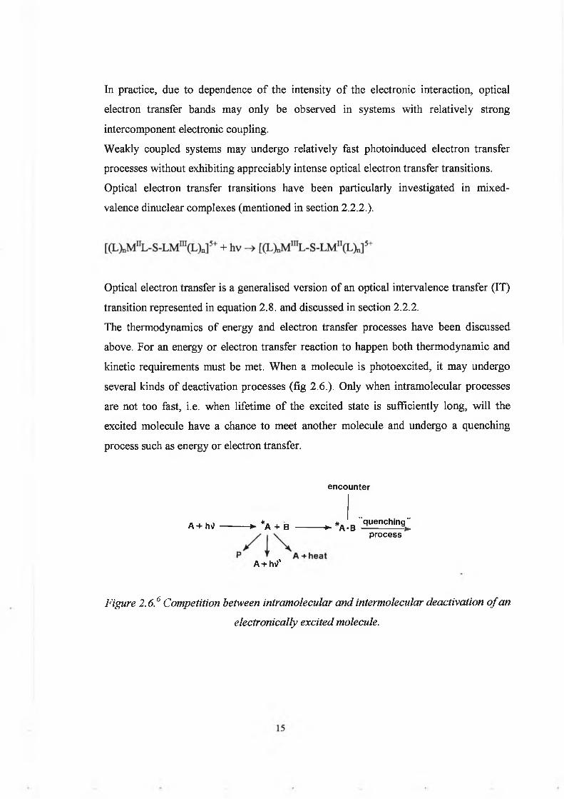
Optical electron transfer is a generalised version o f an optical intervalence transfer (IT) transition represented in equation 2.8. and discussed in section 2.2.2.The thermodynamics o f energy and electron transfer processes have been discussed above. For an energy or electron transfer reaction to happen both thermodynamic and kinetic requirements must be met. W hen a m olecule is photoexcited, it may undergo several kinds o f deactivation processes (fig 2 .6 .). Only w hen intramolecular processes are not too fast, i.e. when lifetim e o f the excited state is sufficiently long, w ill the excited m olecule have a chance to m eet another m olecule and undergo a quenching process such as energy or electron transfer.
encounter
A+h\? +- *A + B „ * . "quenching" *■ A*B ------------*-process
A + htf’
Figure 2.6.6 Competition between intramolecular and intermolecular deactivation o f anelectronically excited molecule.

2.2.4. Design o f multicomponent systems
To perform a particular function, a PM D needs to be constructed o f suitable molecular entities, each having a specific role. In principle, w e may distinguish three fundamental types o f entities:1) Active entities w hich are directly involved in light absorption and/or electron/hole migration (e.g. photosensitiser, electron acceptor, electron donor, energy acceptor).2) Perturbing entities w hich can be used to m odify the properties o f active entities.3) Connecting entities which can be used to link together the active entities.In multicomponent system s, photoinduced charge separation and/or energy migration can only be achieved when the various molecular building blocks are assembled according to w ell-designed geom etric patterns, that is, using covalent bonds.
2.2.4.a. Photosensitisers.4,5’6
The photosensitisers are the key com ponents, i.e. species capable o f absorbing light and transferring energy, electron or hole to another component. The preparation o f M(L)„ core has tw o distinct functions:-Synthesis o f the photosensitiser itself.-Gathering and orienting electroactive com ponents attached to the different ligands.The building blocks to be assem bled must exhibit suitable photochem ical, photophysical and electrochem ical properties. A n excited state should meet several specific requirements in order to be a useful redox reactant for solar energy conversion. It should have a reasonably high energy content, it should be formed with unit efficiency upon light absorption regardless o f the excitation wavelength. It should have a sufficiently long lifetime. It should be a good oxidant and/or reductant and it should be stable towards photodecomposition.Many o f these requirements are met by transition metal com plexes o f metal o f the second and third row with suitable ligands. They often exhibit intense charge transfer bands, that can be strictly populated by light absorption. Because o f a fast and efficient intersystem crossing (due to spin-orbit coupling) the low est excited states are triplet
16
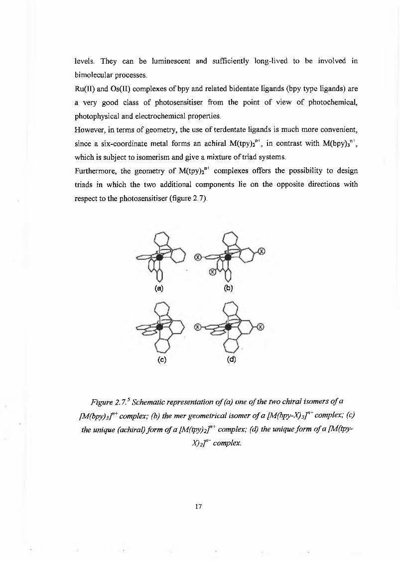
levels. They can be luminescent and sufficiently long-lived to be involved in bimolecular processes.Ru(II) and Os(II) com plexes o f bpy and related bidentate ligands (bpy type ligands) are a very good class o f photosensitiser from the point o f v iew o f photochemical, photophysical and electrochemical properties.H owever, in terms o f geometry, the use o f terdentate ligands is much more convenient, since a six-coordinate metal forms an achiral M (tpy)2n+, in contrast with M (bpy)3n+, which is subject to isom erism and give a mixture o f triad systems.Furthermore, the geometry o f M (tpy)2n+ com plexes offers the possibility to design triads in w hich the two additional components lie on the opposite directions with respect to the photosensitiser (figure 2.7).
(a) (b)
(c) (d)
Figure 2.7.5 Schematic representation o f (a) one o f the two chiral isomers o f a [M(bpy)3] n+ complex; (b) the mer geometrical isomer o f a [M(bpy-X) 3] n+ complex; (c) the unique (achiral) form of a [M(tpy)2] n' complex; (d) the unique form of a [M(tpy-
X)2] n+ complex.
17

Concerning the photophysical, photochem ical and electrochem ical properties, the tpy ligands are less appropriate than the bpy ligands. They have shorter excited-state lifetim es and a much weaker lum inescence intensity. But the lum inescence can be enhanced by use o f appropriate substituents (e.g. M e S 0 2) on the tpy ligand.
2.2.4.b. Electron donor and acceptor.
There are several w ays to build up a system in w hich photoinduced electron transfer can occur. The components D , electron donor, A, electron acceptor and P, the photosensitiser could be covalently linked and four possible arrangements are depicted in figure 2.8. The simplest system is a dyad (fig. 2.8 top)In the two-com ponent system P-A , where A is the electron acceptor and P is the photosensitiser, the back electron transfer is too fast to allow any practical use o f the charge separation process (figure 2.8).P -A + hv ->• *P-A -> P+-A‘ -> P -ASystem s containing three components, triads, are expected to be more efficient because fast secondary electron transfer step(s) can com pete w ith the back electron transfer reaction(s), resulting in a charge separation over large distances.There are tw o possible structures for a triad:
D -P -AD -A 1-A2 (or D 2-D1-P) (figure 2 .8)
The donor and acceptor entities should not absorb light o f w avelength used to excite the photosensitiser, they should have appropriate redox potentials and should be reversible. The m ost w idely used electron acceptors are the vio logen and quinone fam ilies. The m ost com m only used electron donors are the amines.
18
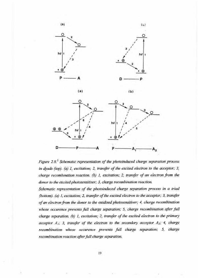
Figure 2.8.5 Schematic representation o f the photoinduced charge separation process in dyads (top), (a) 1, excitation; 2, transfer o f the excited electron to the acceptor; 3, charge recombination reaction, (b) 1, excitation; 2, transfer o f an electron from the donor to the excitedphotosensitiser; 3, charge recombination reaction.Schematic representation o f the photoinduced charge separation process in a triad (bottom), (a) 1, excitation; 2, transfer o f the excited electron to the acceptor; 3, transfer o f an electron from the donor to the oxidised photosensitiser; 4, charge recombination whose occurence prevents fu l l charge separation; 5, charge recombination after fu ll charge separation, (b) 1, excitation; 2, transfer o f the excited electron to the primary acceptor Aj; 3, transfer o f the electron to the secondary acceptor A2; 4, charge recombination whose occurence prevents fu ll charge separation; 5, charge recombination reaction after fu ll charge separation.
2.2.4.C. Energy acceptors.
They should possess excited levels at suitably low energies.They should not undergo excited state reactions.In polynuclear dimetallic com plexes o f Ru(II) and Os(II):-Ru(II), which exhibit high-energy luminescent levels, usually plays the role o f photosensitiser.-Os(II), w hose luminescent levels lie at much low er energy, usually plays the role o f energy accep tor.C om plexes o f the same metal and different ligands can also be coupled for energy transfer processes.
2.2.4.d. Bridging ligands.
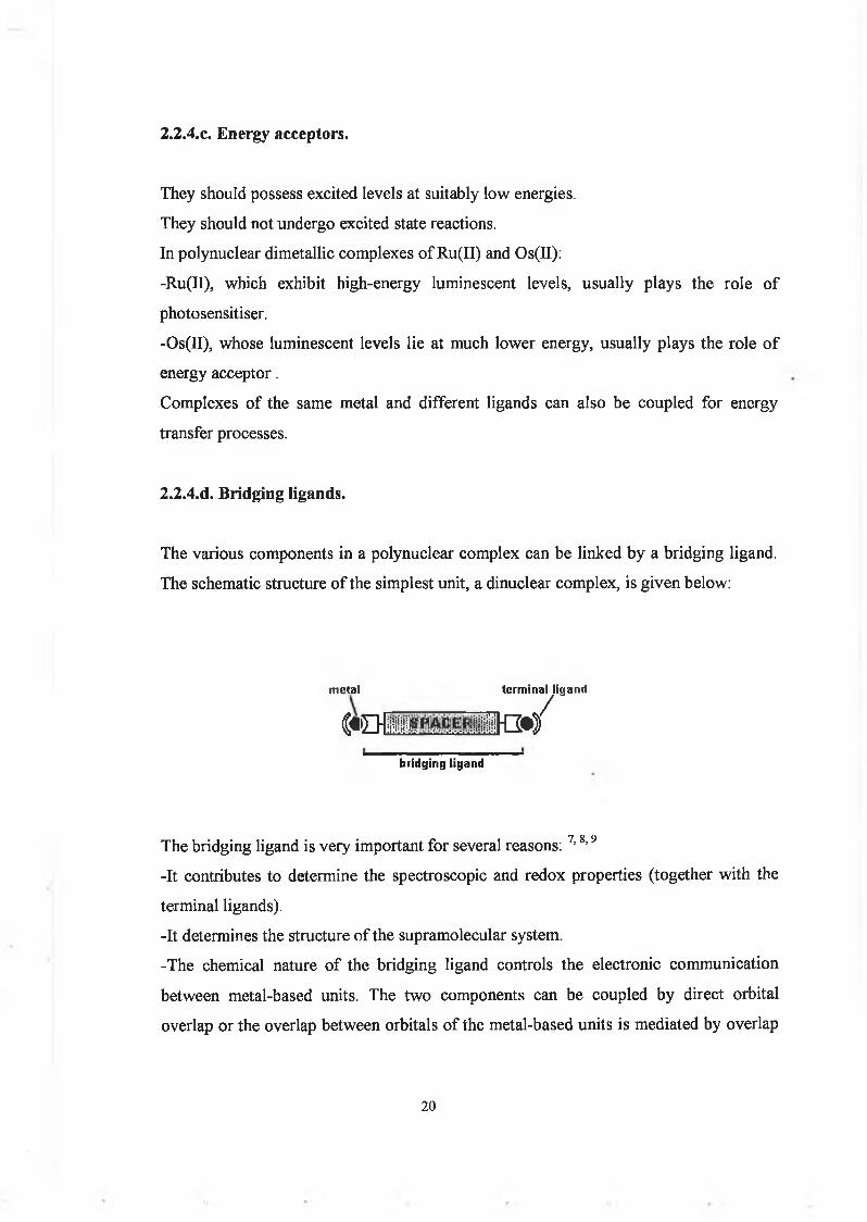
The various components in a polynuclear com plex can be linked by a bridging ligand. The schematic structure o f the sim plest unit, a dinuclear com plex, is g iven below:
metat
C « D i' l ia
terminal ligand
/i i i i a w
bridging ligand
The bridging ligand is very important for several reasons: ?s 8’9-It contributes to determine the spectroscopic and redox properties (together with the terminal ligands).-It determines the structure o f the supramolecular system.-The chemical nature o f the bridging ligand controls the electronic communication between metal-based units. The tw o components can be coupled by direct orbital overlap or the overlap between orbitals o f the metal-based units is mediated by overlap
20

with the orbitals o f the bridging ligand. This is a superexchange m echanism 5. W hen a bridging ligand is made o f one or more subunits the superexchange model has to be further elaborated to include interactions between single subunits.The bridging ligands can be electron-rich or electron-poor. A difference between these tw o cases is that electron-poor bridging ligand can m ediate metal-metal com m unication by a superexchange mechanism based on low -lying, empty n* orbitals o f the bridge (electron-transfer pathway), w hile electron-rich bridges take advantage o f relatively high-lying, full orbitals (hole-transfer pathway).10-The length o f the bridging ligand also plays a role in the electronic coupling. According to standard m odels electron transfer rates are expected to fall o f f exponentially with donor-acceptor distance w hen other parameters are constant.In order to have quantitative innformation, rigid bridging ligands are preferred, because they can assure a fixed distance and geom etry betw een the chromophores. H ow ever it is more difficult to synthesise rigid ligands.
2.2.5. Energy levels o f transition metal complexes.
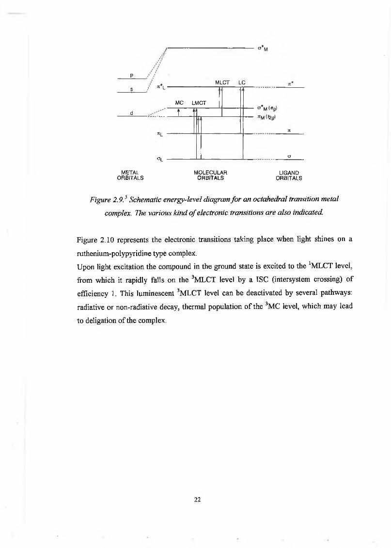
In the approximation o f localised molecular orbital configurations, each M O is labelled as a metal (M ) or ligand (L) according to its predominant localisation.In figure 2 .9 the energy levels for an octahedral com plex are represented.U sually in the ground state, - o l and Ul orbitals are com pletely filled,
-7Um is either partially or com pletely filled,-higher orbitals are empty.
The HOMO is usually metal-centred. W hile the LUM O is either metal- or ligand- centred, depending on the relative energy ordering.W hen the ligand field is sufficiently strong and/or the ligands can be easily reduced, reduction takes place on the ligand.W hen the ligand field is w eak and/or the ligands cannot be easily reduced, the low est empty orbital can be metal-centred.
21
pMLCT LC
s / 7 1 L
MC LMCT
. i
d t “
°L ----------------a
METAL MOLECULAR LIGANDORBITALS ORBITALS ORBITALS
Figure 2.9.5 Schematic energy-level diagram fo r an octahedral transition metal complex. The various kind o f electronic transitions are also indicated.
Figure 2 .10 represents the electronic transitions taking place when light shines on a ruthenium-polypyridine type com plex.U pon light excitation the compound in the ground state is excited to the 1M LCT level, from which it rapidly falls on the 3M LCT level by a ISC (intersystem crossing) o f efficiency 1. This lum inescent 3MLCT level can be deactivated by several pathways: radiative or non-radiative decay, thermal population o f the 3MC level, w hich may lead to deligation o f the complex.
22
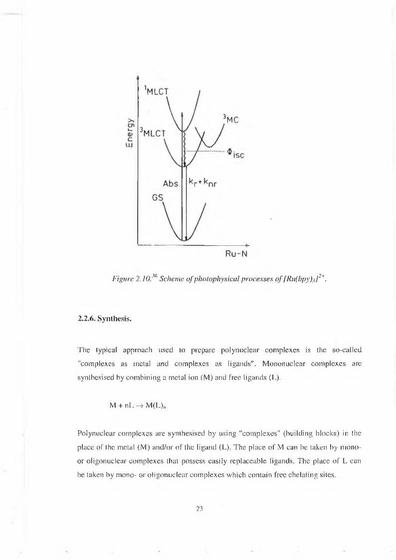
Figure 2 .10M‘ Scheme o f photophysical processes o f [Ru(bpy).i]2*.
2.2.6. Synthesis.
The typical approach used to prepare polynuclear com plexes is the so-called "complexes as metal and com plexes as ligands". M ononuclear com plexes are synthesised by com bining a metal ion (M) and free ligands (L).
M + nL —» M(L)„
Polynuclear com plexes are synthesised by using "complexes" (building blocks) in the place of the metal (M) and/or o f the ligand (L). The place o f M can be taken by mono- or oligonuclear com plexes that possess easily replaceable ligands. The place o f L can be taken by mono- or oligonuclear com plexes which contain free chelating sites.
23

By a clever choice of the reaction partners il is possible to obtain compounds where different metals and ligands can be located in (he desired position of the supramolecular structure (figure 2.11).
Figure 2.1 F. (a) Schematic representation o f the bifunctional [Rufi.S-dppfeCh] and mono functioned [Ru(2,3-Medpp )2Ch]2+ complexes and (b) divergent synthetic strategy
to obtain polynuclear metal complexes o f dendrimier shape.
24

Divergent iterative approach allow s the synthesis o f com plexes containing up to twenty-two metal-centres. It requires availability o f a bifunctional species, e.g. which can behave both as a ligand and as a metal, such as [Ru(2,3-dpp)2Clî].But this species is unavoidably selfreactive under the preparative conditions, leading to compounds o f uncontrolled nuclearity. W e must temporarily block one o f the tw o functions, ex. méthylation o f 2,3-dpp.This approach has allowed the preparation o f large dendrimer shaped polynuclearcom plexes.7’8This iterative synthetic strategy is a full, step-by-step control o f the growing process so that different building blocks containing different ligands can be introduced at each step.
2.2.7. General behaviour o f these compounds.
Before giving som e representative exam ples (see section 3 .1), som e general features o f the polynuclear hom o- or dimetallic polypyridyl com plexes o f Ru(II) and Os(II) w ill begiven.
The first oxidation is metal-centred. Os(II) is oxidised at a less positive potential than Ru(II) (0 .87 V vs 1.30 V vs SCE). The reduction is generally ligand-centred. The absorption spectrum show s very intense absorption bands in the U V region that correspond to ligand-centred transitions (71—> 71*) and moderately intense bands in the visible region that can be assigned to MLCT transitions. The lum inescence spectrum shows em ission originated from the low est 3M LCT excited state. In heterometallic Ru-Os com plexes having the same type o f peripheral ligands energy transfer occurs from Ru(II) to Os(n) since the luminescent levels o f Os(II) lie at low er energy than those o fR u (II).7, M1
25
2.3. The artificial leaf.
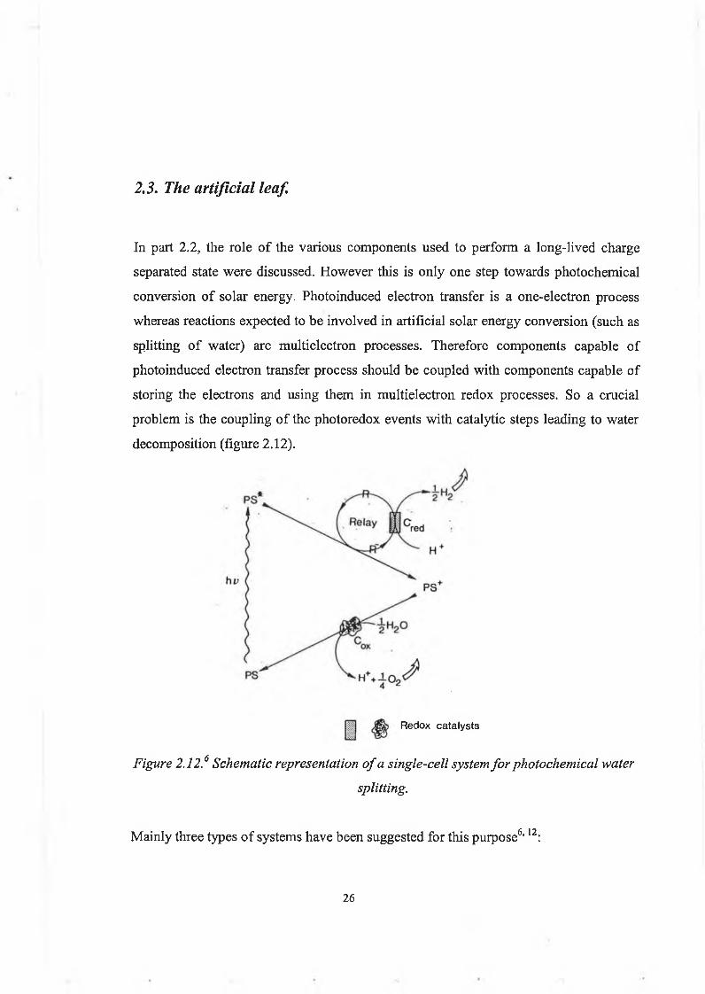
In part 2.2, the role o f the various components used to perform a long-lived charge separated state w ere discussed. H ow ever this is only one step towards photochem ical conversion o f solar energy. Photoinduced electron transfer is a one-electron process whereas reactions expected to be involved in artificial solar energy conversion (such as splitting o f water) are m ultielectron processes. Therefore com ponents capable o f photoinduced electron transfer process should be coupled w ith com ponents capable o f storing the electrons and using them in m ultielectron redox processes. So a crucial problem is the coupling o f the photoredox events w ith catalytic steps leading to water decom position (figure 2.12).
Redox catalysts
Figure 2.12.6 Schematic representation o f a single-cell system fo r photochemical watersplitting.
M ainly three types o f system s have been suggested for this purpose6,12:
26

(i) homogeneous assemblies relying on liquid/liquid interface, such as micelles or vesicles.13,14(ii) heterogeneous systems relying on band gap excitation of a n-type semiconductor.15(iii) heterogeneous systems consisting of combinations of suspended sensitiser and n- type semiconductor loaded with catalyst.16,17The compounds synthesised in this project are studied in solution in the hope that they can be integrated in a dye sensitised semiconductor system.The first successful operation of water cleavage cycle employing Ru(bpy)32+ was achieved by Graetzel and co-workers in 198118. Employing Ru(bpy)32+ as sensitiser and methylviologen as electron relay, light induced injection of electrons into the conduction band of RuC>2 doped TiC>2 catalysed water oxidation. Although this process was inefficient it provided direction for subsequent research on optimising ruthenium polypyridyl sensitisers.To construct an artificial leaf based on a nanocrystalline dye sensitised system, several steps need to be accomplished.The first step is the synthesis and characterisation of suitable molecular components performing a light induced charge separation. Firstly, molecular machines have been investigated. A molecular machine is a multicomponent (supramolecular) system in which reversible changes in the positions (i.e. movements) of its components can be controlled by means of external stimuli such as photons, electrons or suitable chemical species.19' 20, 21 It has been found that pseudorotaxanes, rotaxanes and catenane structures are good candidates for the design of simple molecular machines (figure 2.13).22 Rotaxane and catenane type compounds containing electron donor macrocycles and electron acceptor wires were prepared23. It has been shown that pseudorotaxanes can be dethreaded and rethreaded by chemical, electrochemical means. Such molecular machines can be viewed as switches. Such systems could prove useful for applications in solar energy conversion. For example an electron accepting macrocycle could be used with a electron donating thread compound for the self-assembly of a pseudorataxane.Apart from this type of compounds, ruthenium polypyridyl type compounds attract great interest. This project involved this type of work so some representative examples
27
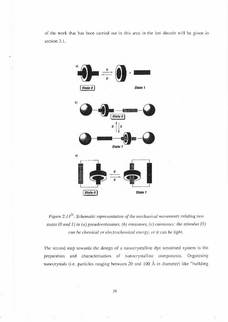
of the work that has been carried out in this area in the last decade will be given in section 3.1.
■o-<tState 0 | State 1
b)
S S
State 1
c)
[ State 0 | State 1
Figure 2.1322. Schematic representation o f the mechanical movements relating two states (0 ancl 1) in (a) pseudorotaxanes, (b) rotaxanes, (c) catenanes: the stimulus (S)
can be chemical or electrochemical energy, or it can be light.
The second step towards the design of a nanocrystalline dye sensitised system is the preparation and characterisation of nanocrystalline components. Organising nanocrystals (i.e. particles ranging between 20 and 100 A in diameter) like "building
28

blocks" into well-defined architectures provides the possibility of employing their unique size-dependent properties in a device.Semiconductors, in particular TiCh, are a proven and very versatile component in the fabrication of dye sensitised solar cells owing to their unique properties of high surface area, transparency and electronic conductivity24. At present the preparation of nanocrystallines TiC>2 surfaces with well-defined morphologies is well understood.Once the behaviours of molecular and nanocrystalline components are investigated, they need to be bound to each other via a covalent linkage to form a heterosupramolecular assembly. When the heterosupramolecular species is constructed we need to see if the desired heterosupramolecular function (such as electron transfer) is performed by the assembly. For this purpose, photophysical and electrochemical experiments can be carried out to check that, for example, there is a charge separation process followed by electron injection into the TiCh (which acts as the relay species and will transfer the electron to a species capable of reduction of water).The last part of the work is to include the heterosupramolecular assembly in a system capable of splitting of water, in a closed cycle, as represented schematically on figure 2.14.
INPUT OF INPUTVISIBLE LIGHT WATER
ENERGY
Figure 2.14.6 Scheme fo r cyclic photochemical water splitting in a coupled catalyticsystem.
29

Chapter 3: Synthesis and characterisation of phenol-containing ruthenium polyppyridyl complexes.
This chapter focuses on experimental work, results and their interpretation for the understanding o f the functioning o f P M D ’s. The first part w ill illustrate som e representative exam ples o f the work on transition metal polypyridyl com plexes performing light induced functions that has been carried out in the last decade. The second part describes the experimental methods I used. The last sections describe the features o f the compounds studied in this project and the experimental work carried out, along with interpretation o f the results.
3.1. Introduction.
3.1 .1 . Figure 3.1 shows a decanuclear com plex with various com binations o f metals illustrating how the excitation energy can be channelled in the desired direction by a suitable choice o f the com ponents.25 In this section, the study and results concerning the dendritic compounds w e are interested in w ill be explained in detail. For the compounds presented in the next sections, only the conclusions w ill be given.The general formula o f these decanuclear com plexes is
M el (BL)M i[(BL)M p(L)2]2 f\320+ (Figure 3 .1)
30

0 = Ru2*
# = Os2+
Figure 3.1." Schematic view of the structure of the decanuclear compounds. N-Nstands for bpy or biq.
where Me is the central metal,Mi are the intermediate metals,Mp are the peripheral metals,
and M = Ru2+ or Os2+.Six compounds have been studied :
Elec trochemi str v
Reduction: very complex pattern because of the 21 ligands all capable of reduction. Oxidation: Previous investigations carried out on mono-, di-, tri, tetra- and hexametallic compounds43 of this family have shown that:
• the electro-donor power decreases in the series bpy > biq > BL.• the interaction between equivalent metals is noticeable for metals coordinated to the
same bridging ligand, whereas it is negligible for metals that are sufficiently far apart.
Mc A Mp L
1 Ru . Ru Ru bpy2 Ru Ru biq3 Os Ru Ru bpy4 Os Rii ' Ru .‘biq
0» r;./ Ru lO% bpy6 Ru Ru Os bpy
31
The electrochemical behaviour of the decanuclear compounds is fully consistent with such treatments.
Absorption spectra
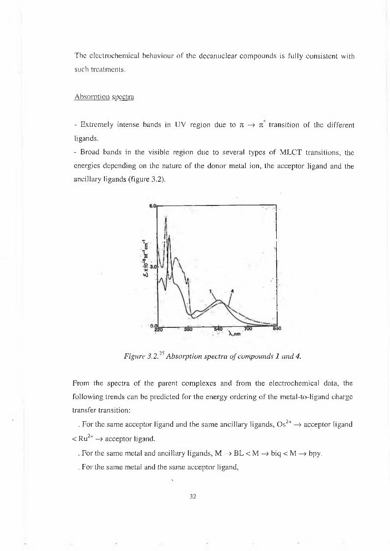
- Extremely intense bands in UV region due to n —> n transition o f the different ligands.- Broad bands in the visible region due to several types of M LCT transitions, the energies depending on the nature of the donor metal ion, the acceptor ligand and the ancillary ligands (figure 3.2).
Figure 3.2." Absorption spectra of compounds 1 and 4.
From the spectra of the parent com plexes and from the electrochemical data, the following trends can be predicted for the energy ordering of the metal-to-ligand charge transfer transition:
. For the same acceptor ligand and the same ancillary ligands, Os2+ —> acceptor ligand < R u2+ —> acceptor ligand.
. For the same metal and ancillary ligands, M —> B L < M —> biq < M —> bpy.
. For the same metal and the same acceptor ligand,N
32
(bpy)2M —» acceptor ligand < (biq)2M - » acceptor ligand <(B L )2M —> acceptor ligand.
Lum inescence properties and intercomponent energy transfer
In the Ru(II) and Os(II) polypyridine com plexes lum inescence originates from the low est 3MLCT excited state. Deactivation o f the upper excited state to the low est one by an exchange mechanism is a very fast (picosecond tim e scale) and highly efficient (100 %) process. On the basis o f the electrochemical behaviour and the absorption spectra o f compounds 1-6 and o f the properties o f parent com pounds, it can be expected that the energy o f the (low est) MLCT excited state o f the various com ponents w hich are present in the decanuclear compounds increases in the series (bpyhOsp - » BL < (BLhOSc —» BL < (bpy)2Rup —> BL < (biq)2Rup - » BL < (BL^Ru; —» BL < (BL^Ruo —> BL.The luminescent properties o f com pounds 1-6 can be discussed on the basis o f the above expectations and o f the occurrence o f intercomponent energy transfer processes. The directions along with such processes are exoergonic are schem atically indicated by arrows in figure 3.3. 1 and 2 emit from the peripheral (bpy)2Ru —» B L excited states. They both exhibit energy transfer from the central and intermediate units to the peripheral units, as expected because energy transfer is exoergonic from the centre to the periphery. 3 and 4 emit from both the central and peripheral units. Such a behaviour is consistent with the fact that in 3 and 4 the low est excited state o f the intermediate Rui-based units lie at higher energy (-2000 cm '1) than the low est excited state o f the peripheral units and therefore act as an "insulator". Thus for 3 and 4, the two-step energy transfer process from the peripheral units to the central one (where the low est energy excited state o f the supramolecular array is located) must be very slow since its first step is endoergonic by ~ 2000 cm"1. Direct (through space) energy transfer from the peripheral to the central units is exoergonic but should be slow because o f the large separation distance. From a comparison o f the lum inescence lifetim e data for 1 and 3 and 2 and 4, respectively, it is clear that the quenching o f the peripheral excited states by the central one in 3 and 4 is negligible. For 5 and 6 the low est excited states are localised on the peripheral (bpy)20s -> BL units which are expected to emit around
33

900-950 nm, which is outside the sensitivity range o f the equipment that the authors used for their experiments. The lack o f lum inescence for 6 is an expected result in v iew o f the central-to-periphery gradient for energy transfer, as shown in figure 3.3. For 5
deactivation o f the central Os-based unit by the peripheral ones should not occur because the first step o f this process is endoergonic. The lack o f observable lum inescence from such a central unit may simply be due to the fact that most o f the light, at any excitation wavelength, is absorbed by m uch more numerous peripheral and intermediate units.It is clearly shown here that the excitation energy can be channelled in the desired direction (e.g ., from the centre to the periphery or v ice versa) by a suitable choice o f the components.Strong absorption in the visib le range and the possibility to predetermine the direction o f energy migration are important properties for the design o f photochemical m olecular devices.
Figure 3.3.25 Schematic representation o f the energy transfer processes in the decanuclear compounds. The arrows indicate the exoergonic energy transfer steps.
Empty and fu ll circles indicate R i f+ and Os2+, respectively. In the peripheral positions, circles and squares indicate M(bpy) 2 andM(biq) 2 components, respectively.
34
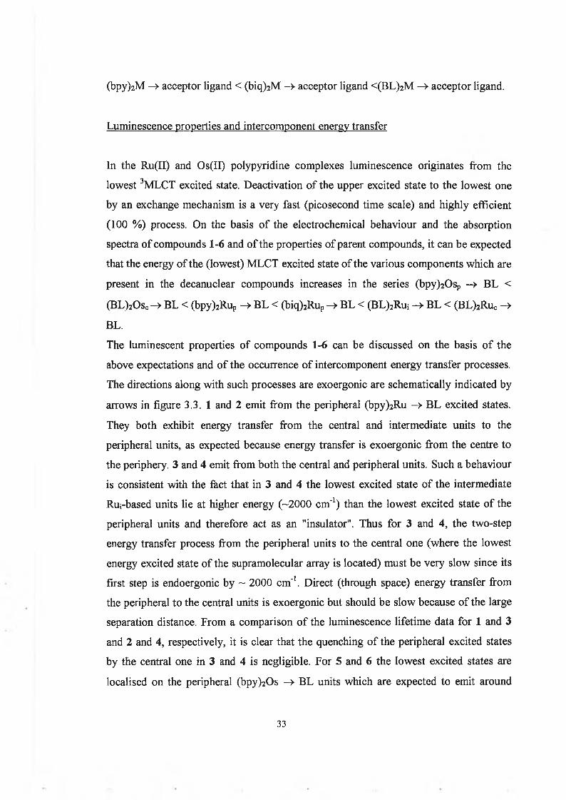
3.1.2 . Figure 3.4 show s a tetranuclear com plex in w hich electron transfer occurs through a superexchange m echanism .10This is the first case o f a tetranuclear Ru(II) com plex containing both electron-rich and electron-poor bridging ligand.The general formula is:L(bpy)2-Ru-((i-bpt)-Ru-{((i-2,3-dpp)-Ru-(bpy)2} 2 ]7+ 1
■I' >i- IA C B
The electron-rich ligand is (3,5-b is(pyridyn-2-yl)-l,2 ,4-triazole) (=Hbpt)The parent com plexes that have also been studied are:
[R u{(^2,3-dpp)R u(bpy)2}3]8+ 2[(bpy)2Ru(p,-bpt)Ru(bpy)2]3+ 3
(-)C\C'hO Q-O 0-0 OtfrO^ I n . ,bpy 2,3-dpp bpt
Fig. 3.4.10 Structural formulas o f the polypyridine ligands and schematic representation o f 1 (N-N stands fo r bpy). The Ru metals are labeled as in the text.
Excited states and oxidation and reduction processes are localised on specific sites o f the m ulticom ponent structure. H owever, perturbations o f each component on the redox and excited states o f the others, as w ell as electronic interaction between the chromophores can be observed.
35

The absorption spectrum of 1 is dominated by LC bands in the UV region and MLCT bands in the visible region. Intercomponent energy transfer from the upper-lying (|j.- bpt)(bpy)Ru —» bpy CT excited state of the Ru(bpy)2 (jx-bpt)+ component to the lower- lying (bpy)iRu —> |U.-2,3-dpp CT excited state of the Ru(bpy)2 (|a-2 ,3 -dpp)2+ subunit is efficient in 1 in fluid solution at room temperature but this process is not observed in a rigid matrix at 77 K. To explain that, a two-step energy-transfer is proposed. The first step leads to a "remote" CT level *(bpy)2 Ru(p.-bpt)+ _> (ji-2 ,3 -dpp)Ru(bpy)2 2+. The second step involves a hole-transfer superexchange mechanism involving bpt, Ruc, reduced 2,3-dpp (This yields to a strong long-distance M -M communication between oxidised R u 111 and donor Ru 11 (Figure 3.5).It has been observed that 2,3-dpp or 2,5-dpp allows a weak interaction in all of these compounds. The presence of (x-bpt in the last compound allows a hole-transfer superexchange mechanism.
Ru
r j r -2,3-dpp
/ O 'K-tipt(-) w ✓ bpy— Ri RJ — bpy
I Ibpy bpy
II
H-2,SPP— Ru nu — bpy
bpy
bpy bpy I* <♦>
H.s-jfpp (-)
/fc\|rf>P« |i-Z,3-dpbW— Ru Ri — bpy
bpy tj|y
bpy
Figure 3.5.10 Electron transfer processes which are proposed to be involved in 1 and 4 to mediate intercomponent energy transfer processes.
36

3.1.3. This example illustrates a compound containing a rigid spacer, which is a tris(bpy) tripod ligand.26
The three different spacers used and the series of nine complexes which have been
Figure 3.6.26 Stucturalformulas o f the bridging ligands 1, 2 and 3, and o f thetrimetallic complexes.
-All the complexes show very intense ligand based absorption bands in the UV region and moderately intense MLCT in the visible region.-The electrochemical oxidation of Ru21 or Os2+ occur always at the same potential.-The five homometallic Ru(ll) species show the same luminescence properties (idem for homometallic Os(II) species).What has been said above shows that the interaction of M(bpy)iL2+ component with any other component is very weak.
37

-The two mixed-metal species exhibit energy transfer from Ru-based to Os-based component.-The efficiency of energy transfer decreases as the size of the spacer increases.-The mixed-valence species show a quenching of the luminescent excited state from oxidised metal-based unit to units that are not oxidised by electron transfer processes.
3.1.4. Some examples of rigid rod-like dyads using polyphenylene spacers to illustrate the importance of the bridging ligand used (nature and distance between metal centres) on the rates of energy and electron transfer processes.This section will also illustrate the importance of the metals and peripheral ligandsused.
Recently particular attention has been focussed on the use of polyphenylene spacers. Such bridges represent a good compromise between the following requirements: (i) be rigid, to avoid conformational problems, (ii) be electronically "innocent", to preserve the supramolecular nature of the system, (iii) provide good intercomponent coupling.
3.1.4.a. Ru(H)/Os(II) terpyridine-type complex.27
The general formula is: (Xitpy)Ru(tpy(Ph)ntpy)Os(tpyX2)4
Different substituents X have been used, (figure 3.7)The absorption spectra of the two components are slightly perturbed in the dinuclear compounds, and metal-metal and ligand-ligand interaction are evidenced by the trends of the oxidation and reduction potentials.When n=0, the interaction is strong.When n=l or 2, the interaction is less strong but the phenylene spacers have a relatively small insulating effect.In each dinuclear compound the excitation energy absorbed by the Ru-based unit is quantitatively transferred to the Os-based unit, by a Dexter mechanism.A fast energy transfer takes place in all the dinuclear compounds, even when the two chromophores are separated by two phenylene bridges
38

-X =
-X =
-X »
tpy
;H 3 Meph— tpy
-SOzMe : Me02S — tpy
n = 0
n=.1 . n = 2 *
K H
tpy— tpy
tpy— ph— tpy
tpy— (ph)2— tpy
* 2
• Ru2+o Os2 +1 X, = X 2 =ph Me, n = 02 Xi = X2 = p h M e , n = 13 = X 2 = Ph M e , n = Z
Nu 4 Xi =S0 2 Mo,X2 = H ( n - 0
5 X T = S 0 2 M e , X 2 = H , n =1
6 Xi = S 0 2 M e , X2 = ph M e , n =2
9 7Figure 3 .7.' Schematic structure o f the dinuclear complexes.
3.1.4.b. Ru-Rh terpyridine-type complex. 28,29
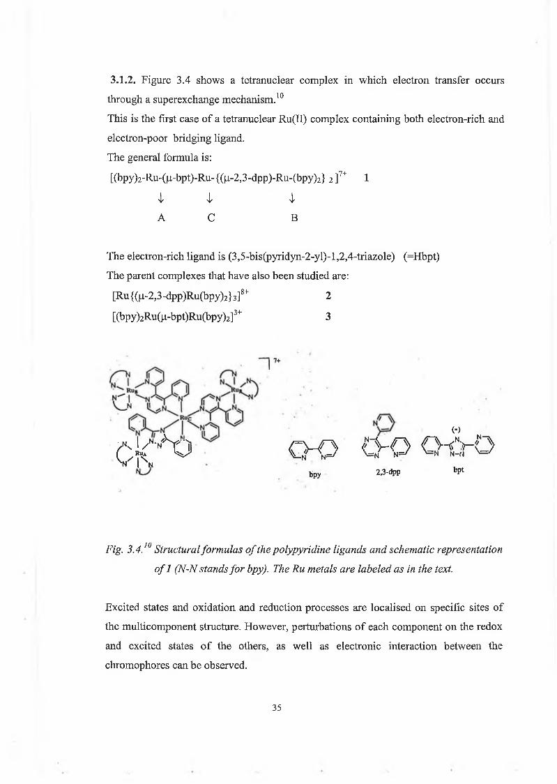
A series of dyads of general form ula 1 have been prepared (figure 3.8).Energy transfer is energetically forbidden in these systems, unlike the similar Ru-Os complexes.The dyads were designed with the Ru-based unit as the photoexcitable molecular component and the Rh-based unit as the electron acceptor (photoinduced electron transfer is allowed, its actual efficiency depends on the competition with the excited state deactivation).
39
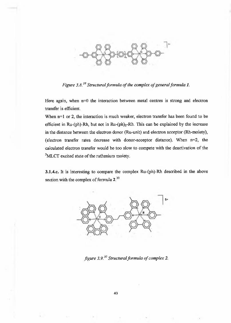
Figure 3.8 .28 Structural formula o f the complex o f general formula 1.
Here again, when n=0 the interaction between metal centres is strong and electron transfer is efficient.When n=l or 2, the interaction is much weaker, electron transfer has been found to be efficient in Ru-(ph)-Rh, but not in Ru-(ph)2-Rh. This can be explained by the increase in the distance between the electron donor (Ru-unit) and electron acceptor (Rh-moiety), (electron transfer rates decrease with donor-acceptor distance). When n=2, the calculated electron transfer would be too slow to compete with the deactivation of the 3MLCT excited state of the ruthenium moiety.
3.I.4.C. It is interesting to compare the complex Ru-(ph)-Rh described in the above30section with the complex of formula 2 .
figure 3.9.30 Structural formula o f complex 2.
40
The two dyads are similar in driving force and reorganisational energies. Thus the main difference lies in the coupling provided by the bridge. It is seen that although the metal- metal distance is longer in Ru-(ph)-Rh the electron transfer is faster. This is a clear indication that not only the length but also the nature of the bridge are of importance to the electron transfer efficiency.
3.1.5. Ru polypyridine complexes entrapped in zeolite supercages.31'34
With regard to the interest in photophysical and photochemical properties of Ru polypyridine complexes because of their potential utility as components of practical solar energy conversion devices, it was expected that development of efficient systems would require the incorporation of these or other types of photosensitisers into organised assemblies which position the various components, in terms of both reactivity and spatial distribution, so as to facilitate net chemical conversion. An attractive approach to produce appropriately designed assemblies is to employ superstructured matrices which can serve as a framework for attachment or incorporation of the various components. Of these types of matrices, the readily available and structurally well- characterised zeolites have received considerable attention. The Y-type zeolite is of special interest with regard to the utilisation of the polypyridine complexes of Ru because this particular zeolite structure provides "supercages" having an internal diameter (13 A ) which is sufficiently large to accommodate polypyridine complexes . Once formed, the chemically robust complex is entrapped within the supercage, being too large to migrate out through the windows (~7 A ). Electronic absorption, as well as resonance Raman spectra of most of the entrapped complexes studied show no significant difference in comparison to the solution phase complexes. However entrapment in zeolite supercages dramatically affects the photophysics of the complexes. It leads to increases in the energy of the 3dd state due to steric restriction on Ru-N bond. This prevents population of this energy level (which is usually followed by a fast non-radiative decay or ligand loss). This effect has two important consequences:
. It may lead to increases in room temperature lifetime.
41
. Il eliminates serious problem of photodecomposition (deligation) of these complexes which proceeds through thermal population of the ’dd state.
So it has been observed that complexes with quite unfavourable inherent photophysical properties (short JM LCT lifetime and susceptibility of photoinduced ligand loss) can be converted to a more promising photosensitiser by incorporation into an Y-zeolite supercage.
3.1.6. Conclusion.
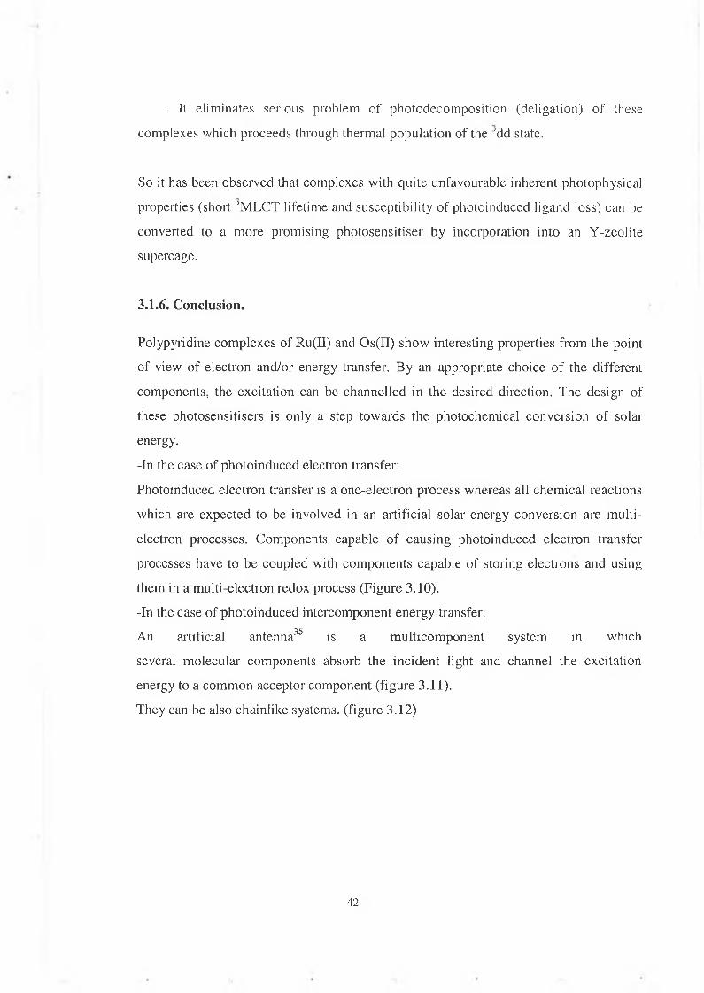
Polypyridine complexes of Ru(II) and Os(II) show interesting properties from the point of view of electron and/or energy transfer. By an appropriate choice of the different components, the excitation can be channelled in the desired direction. The design of these photosensitisers is only a step towards the photochemical conversion of solar energy.-In the case of photoinduced electron transfer:Photoinduced electron transfer is a one-electron process whereas all chemical reactions which are expected to be involved in an artificial solar energy conversion are m ultielectron processes. Components capable of causing photoinduced electron transfer processes have to be coupled with components capable of storing electrons and using them in a multi-electron redox process (Figure 3.10).-In the case of photoinduced intercomponent energy transfer:An artificial antenna3 5 is a multicom ponent system in which several molecular components absorb the incident light and channel the excitation energy to a common acceptor component (figure 3.11).They can be also chainlike systems, (figure 3.12)
42
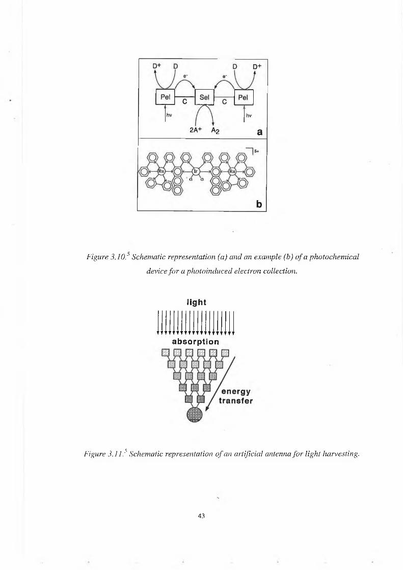
Figure 3.10.:> Schematic representation (a) and an example (b) o f a photochemical device fo r a photoinduced electron collection.
light
absorption
Figure 3.11.5 Schematic representation o f an artificial antenna fo r light harvesting.
43

Luminescent and redox-active polynuclear complexes can play a role as PMD's operating by photoinduced energy and/or electron transfer processes. The progresses to be made in this area are:
- the design of new luminescent and redoxactive building blocks.- the synthesis of new modules to construct spacers having well-defined structures
(rod, rings, ribbons etc) and properties (insulating, conductive, photosensitive etc.). Substantial benefit will also come from improvement of experimental techniques (like MS FAB, ESMS etc.) which are capable of characterising large and electrically charged arrays.
a
Figure 3.12.5 (a) a small antenna made o f trinuclear compound and (b) a chainlikeantenna.
4 4

3.2: Experimental part.
3.2.1. Synthesis.
Preparation o f ligands.
The ligands structures are shown in figure 3.13.
H2L1 H2L2
Figure 3.13.a. 3-(2-phenol)-5-(pyridin-2-yl)-l,2,4-triazole (H2LI), 3-(2-phenol)-5-(pyrazin-2-yl)-l,2,4-triazole (H2L2).
3-(2-phenol)-5-(pyridin-2-yl)-l,2,4-triazole (H2LI)
• • •The ligand was prepared via a method described by Hage . 60g (0.4 mol) ofmethylsalicylate was combined with a slight excess of hydrazine hydrate in ethanol (20
cm3). The mixture was left stirring at room temperature for 3 hours and then left underrefrigeration overnight. The white crystalline product was collected by filtration(salicylate hydrazide).5g (0.048 mol) of cyanopyridine was combined with a catalytic amount of sodium metal m 120 cm of methanol, m which the mixture was refluxed for 2 hours. This produced methyl-2-picolinimidate which was then refluxed with equimolar salicylate
t ohydrazide for 2 hours in ethanol (50 cm ). The reaction mixture was concentrated to 20
45
cm3 and allowed to cool, the resulting yellowish solid was collected by filtration and dried. Cyclisation took place by refluxing the product in ethylene glycol for 30 minutes. The product was then collected by filtration.Yield= 15%. Mp: 212°C (literature 221-222°C).‘H-NMR, (DMSO-dô, ppm): 8.20, (d, 1H, H3); 8.0, (t, 1H, H4; d, 1H, H3”); 7.35, (t, 1H, H5); 8.75, (d, 1H, H6); 7.0, (m, 1H, H4”; m, 1H, H6”); 7.55, (t, 1H, H5”).
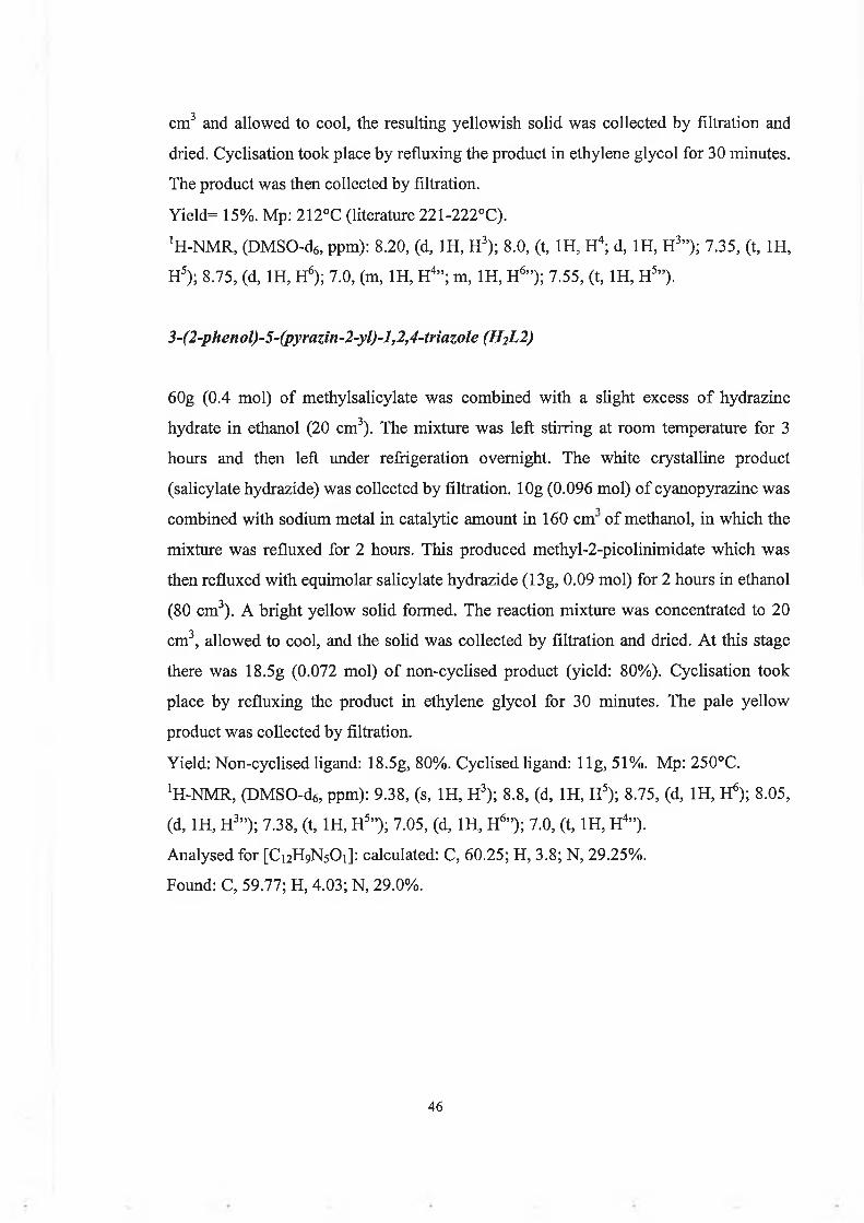
3-(2-phenol)-5-(pyrazin-2-yl)-l,2,4-triazole (H2L2)
60g (0.4 mol) of methylsalicylate was combined with a slight excess of hydrazine hydrate in ethanol (20 cm3). The mixture was left stirring at room temperature for 3 hours and then left under refrigeration overnight. The white crystalline product (salicylate hydrazide) was collected by filtration. 10g (0.096 mol) of cyanopyrazine was
•icombined with sodium metal in catalytic amount in 160 cm of methanol, in which the mixture was refluxed for 2 hours. This produced methyl-2-picolinimidate which was then refluxed with equimolar salicylate hydrazide (13g, 0.09 mol) for 2 hours in ethanol (80 cm3). A bright yellow solid formed. The reaction mixture was concentrated to 20 cm3, allowed to cool, and the solid was collected by filtration and dried. At this stage there was 18.5g (0.072 mol) of non-cyclised product (yield: 80%). Cyclisation took place by refluxing the product in ethylene glycol for 30 minutes. The pale yellow product was collected by filtration.Yield: Non-cyclised ligand: 18.5g, 80%. Cyclised ligand: llg , 51%. Mp: 250°C. ‘H-NMR, (DMSO-de, ppm): 9.38, (s, 1H, H3); 8.8, (d, 1H, H5); 8.75, (d, 1H, H6); 8.05, (d, 1H, H3”); 7.38, (t, 1H, H5”); 7.05, (d, 1H, H6”); 7.0, (t, 1H, H4”).Analysed for [C12H9N5O1]: calculated: C, 60.25; H, 3.8; N, 29.25%.Found: C, 59.77; H, 4.03; N, 29.0%.
46

Preparation of mononuclear complexes.
The ruthenium unit can potentially bind the ligands H2L1 and H2L2 at the (N,N)-site or at the (0,N)-site. Only the (N,N)-coordinated complexes were prepared.
Ru(bpy)2(HLl)]PF6.2CH3OH
_This complex was prepared as described by Hage .H2LI (0.3g, 1.25 mmol) was dissolved in ethanol/water (1:1 v/v) 50 cm3. Ru(bpy)2Cl2.2H20 (0.5g, 1 mmol) was added over 30 minutes to this solution (a slight excess of ligand was used to make sure that only the mononuclear complex is formed) and the mixture was refluxed for 3 hours. After reaction the mixture was filtered and
•2 _ ^the volume reduced under vacuum to 10 cm . A few drops of concentrated NH4PF6
were added to this solution until precipitation ceased, and the orange solid was collected under vacuum. The complex was recrystallised from acetone/water 1:1 v/v. After recrystallisation the yield was 0.6g (85%), and the complex was 80% pure based on HPLC analysis. The complex was purified on an alumina column, the mobile phase was methanol/water 9:1 v/v, containing KNO 3 salt in concentration 0.1M. The complex was pure after passing it through the alumina column according to HPLC analysis. Yield: 23%. ‘H-NMR, (CH3CN-d3, ppm): 8.15 (d, 1H, H3); 8.0 (m, 1H, H4; 1H, H3”); 7.53 (d, 1H, H6); 7.3 (t, 1H, H5”); 7.15 (t, 1H, H5); 6.8 (m, 1H, H6”; 1H, H4”).Bipyridyl resonances could not be assigned to individual rings but were observed to occur in the following regions:
H3 H4 H5 H6
8.3-8.7 7.6-8.2 7.2-7.5 7.9-8.15Analysed for [RuiC35H33Ng0 3PiF6]: Calculated: C, 48.9; H, 3.84; N, 13.0 %. Found: C, 49.4; H, 3.64; N, 12.61 %.
47
[Ru(bpy)2(HL2)]PF6.H20
H2L2 (0.25g, 1.045 mmol) was refluxed for a few minutes in ethanol/water (25/15 cm3). Ru(bpy)2Cl2.2H20 (0.45g, 0.86 mmol) was added to the solution over 30 minutes and the mixture was refluxed for a further 3 hours 30 minutes. The mixture was allowed to cool, filtered and evaporated under vacuum to 10 cm3. A few drops of concentrated NfUPFe were added to this solution until precipitation ceased and the orange solid was collected by filtration. The product was washed with water and diethyl ether and recrystallised in acetone/water 1:1 v/v.After recrystallisation, the yield was 99%, the HPLC analysis revealed that the complex was 87% pure. For purificarion purpose, the complex (0.105g) was dissolved in CH3CN/H2O 8:1 v/v, containing KNO3 0.1M and was passed through an alumina column. The product came off the column in 2 fractions, the first one was pure according to HPLC and elemental analysis.Yield: 87 mgs (80%). !H-NMR, (CH3CN-d3, ppm): 8.3 (d, 1H, H5); 7.9 (d, 1H, H3”); 7.65 (d, 1H, H6); 7.2 (t, 1H, H5”); 6.85 (m, 1H, H4”; 1H, H6”).Bipyridyl resonances occur in the same regions as mentioned above for [Ru(bpy)2(HLl)]PF6.Analysed for [RuiC32H26N9Rui02PiF6]: calculated: C, 47.2; H, 3.2; N, 15.45.Found: C, 47.03; H, 3.08; N, 14.86.
Preparation o f dinuclear complexes.
[(Ru(bpy)2)2(L2)](PF^2.4H20
0.15g (2.3x1 O’4 mol) of [Ru(bpy)2(HL2)]PF6 were dissolved in ethanol/water (30•a o _ _cm /20 cm ). The pH of the solution was brought to 12 by adding NaOH, in order to
deprotonate the phenol to make it free for coordination to the Ru centre. This was left refluxing for a few minutes to ensure deprotonation of the phenol and then 0.135g (2.6x10^ mol) of Ru(bpy)2Cl2.2H20 were added and left refluxing for 4 hours . The solution turned into a dark brown colour. It was left to cool before neutralising it with
48

concentrated H2SO4. The solution was subsequently evaporated to about 10 cm3. NH4PF6 salt was added until precipitation of the solid stopped. The dark brown solid product was filtered and washed with H2O and diethyl ether and recrystallised in acetone/water.Yield: 0.185g (50%). The HPLC analysis revealed two fractions, the first one came off after 2.9 minutes and its peak area was 4%, the second one came off after 6.4 minutes and its peak area was 96%. This suggests that the reaction mixture contains the dinuclear complex in high proportion, with a residue of mononuclear complex. The compound was further purified on an alumina column. Several combinations of solvent and salt were tried, the best one purified the dimer to a peak area of 98%, with a yield of 30%. The elemental analysis suggests that the compound is pure.'H-NMR: see figure in section 3.5.2. Analysed for [Ru2C52H47Ni305P2Fi2]: Calculated: C, 43.8; H, 3.3; N, 12.75 %. Found: C, 43.3; H, 2.84; N, 12.3 %.
[(Ru(bpy)2)2(Ll)](PF() 2.4H2 0 .C3H60 .
0.15g (2.3x10‘4 mol) of [Ru(bpy)2(HLl)]PF6 were dissolved in ethanol/water (30 cm3/20 cm3). The pH of the solution was brought to 12 by adding NaOH, in order to deprotonate the phenol to make it free for coordination to the Ru centre. This was left refluxing for a few minutes to ensure deprotonation of the phenol and then 0.135g (2.6x1 O’4 mol) of Ru(bpy)2Cl2.2H20 were added and left refluxing for 4 hours . The solution turned into a dark brown colour. It was left to cool before neutralising it with concentrated H2SO4. The solution was subsequently evaporated to about 10 cm . NH4PF6 salt was added until precipitation of the solid stopped. The dark brown solid product was filtered and washed with H20 and diethyl ether and recrystallised in acetone/water.The yield and purity of the complex are very similar to those of [(Ru(bpy)2)2(L2)](PFe)2.420, (a yield of 50% and a peak area of 95% in the HPLC analysis). Purification on an alumina column was tried with various combinations of solvent and salt, but the peak area in the HPLC analysis remained unchanged. Nonetheless the values found for the elemental analysis correspond to the calculated
49
values. H-NMR: see figure in section 3.5.2. Analysed for [RU2C56H52N 12O6P2F12]: Calculated: C, 45.3; H, 3.5; N, 11.33%. Found: C, 45.26; H, 3.15; N, 11.67%.
3.2.2. Analytical HPLC.
Analytical cation exchange HPLC measurements were carried out using a Waters HPLC system. The detector was a photodiode array.The mobile phase was 80:20 acetonitrile/water containing 0.1 M LiCIO,*. The flow rate used was 1.3 ml/min. The samples were detected at 280 nm.The "purity" of the compounds analysed by HPLC has been given in percentage based on peak area. It is realised that this is formally incorrect since extinction coefficients have to be taken into account. This simple method is however quite useful to assess purity of samples.
3.2.3. Nuclear magnetic resonance.
Proton NMR spectra were carried out on a Bruker AC400 (400 Mhz) instrument. The solvents used were deuterated dimethyl sulfoxide for the ligands and deuterated acetonitrile for the complexes. The chemical shifts were recorded relative to TMS.
3.2.4. Acid/base titrations.
For the titrations a solution of known concentration (about lO^M) of the complex in Britton-Robinson buffer (0.04M H3BO3, 0.04M H3PO4, 0.04M H3CCOOH) was prepared.For the ground state pKa’s, absorption spectra were recorded in the pH range from 1 to13. The pH was varied with concentrated H2SO4 or NaOH. Then a plot of percentage change in absorbance (Aabs) vs pH is drawn and the inflexion point gives the pKa, where Aabs [(abspH absfjnaipH)/(ahs injtiaipii abs fmaipH)]xl00.For the excited state pKa*'s, emission spectra were recorded in the pH range from 1 to12.8. The excitation wavelength is the isobestic point of the absorption spectra. The plot
50

of percentage change in emission intensity vs pH gives an inflexion point which is not the real pKa\ because it needs to be corrected for the lifetimes of the protonated and deprotonated species, (see equations in section 3.4.4).
3.2.5. Electrochemistry.
Cyclic voltammetry was carried out in dimethyl formamide, acetonitrile and methanol. The electrolyte used was tetraethylammoniumperchlorate (TEAP) or tetraethylammoniumtetrafluoroborate (TEATFB) in concentraition of 0.1 M. Sample concentrations were about 0.1 M. The working electrode was a 3mm diameter glassy carbon electrode, the reference electrode was a saturated calomel electrode or a Ag/AgCl electrode, and the auxiliary electrode was a platinum gauze. The electrochemical cell employed was a triple compartment with glass frits. The analyte was degassed for use of cathodic potentials. The scan rates applied varied from 0.1 to 0.5 V/s.Perchloric acid was used to protonate the triazole moiety, and diethylamine to deprotonate the phenol ring.The electrochemistry of [Ru(bpy)2-HL1]+ caused no problem. It was carried out in acetonitrile containing 0.1M of TEAP. [Ru(bpy)2-HL2]+ was problematic. In the same conditions as for [Ru(bpy)2-HL1]+ no clear and reversible waves could be obtained. A few other solvents were tried (dimethylformamide and methanol), the voltammograms were slightly clearer in methanol (stronger intensity). Thoroughly dried acetonitrile and TEATFB were used (TEAP might contain some acid, which would affect the electrode), but the peaks were still very weak and irreversible. This might be due to polymerisation of the phenol onto the carbon electrode.
3.2.6. Spectroelectrochemistry.
Spectroelectrochemistry measures the changes in absorbance when a potential is applied to the studied compound.
51

The working electrode was platinum gauze, the auxiliary electrode was a platinum wire and the reference electrode was a Ag/AgCl electrode.The concentration of the sample was about 0.1 M. The solvent used was acetonitrile and the electrolyte TEATFB (in concentration of 0.1 M).
3.2.7. Absorption and emission measurements.
UV-vis spectra were carried out using a Shimadzu UV-240 spectrophotometer.Emission measurements were carried out on a Perkin Elmer LS50 luminescence spectrometer.The solvent used was spectrograde acetonitrile.
3.2.8. Excited state lifetime measurements.
Luminescent lifetimes were carried out on a Q-switched Nd-YAG spectrum laser system. The excitation wavelength was 355 nm. Room temperature measurements were carried out in acetonitrile. Samples were of very low concentration i.e. lO'4 -10'5 M. Samples were degassed by bubbling nitrogen through the sample for 20 minutes.
3.2.9. Hyperchem.
Structure optimisations were carried out using Hyperchem as developed by Hypercube. Standard parameters were used and the structures obtained should only be read for visionalisation purposes.
52

3.3: Results and discussion.
This project involves the synthesis and characterisation of novel ruthenium(bipyridyl)2
complexes containing a triazole ring and a phenol grouping. The properties of H2L1, its mononuclear and its dinuclear complex, as described in Keyes2 and Hage36, and of H2L2, a novel ligand, and its mononuclear complex and dinuclear complex are investigated. H2L2 contains a pyrazine ring whereas H2LI contains a pyridine ring. Pyrazine is a better electron acceptor than pyridine and interesting properties have been observed in complexes containing a pyrazyltriazole (Hpztr) ligand46 (see figure 3.13). Complexes containing H2L1 are interesting as well because the phenolate is a good quenching agent.40 The aim of this project is to study the electrochemical and photophysical properties of complexes containing H2L2 and compare them to those of complexes containing H2LI and Hpztr.The ligands studied in this work are represented in figure 3.13.As mentioned in section 2.1. it has been found in the last decades that ruthenium-polypyridine chromophores are attractive candidates for excited state electron transferprocess in fluid solution, in particular Ru(bpy)32+, which is well known and serves as acomparative model for the study of other ruthenium-polypyridyl complexes. Here aresome features6 of Ru(bpy)32+ which make this compound interesting. Ru(bpy)32+ has anoctahedral structure. Under normal chemical conditions the stable oxidation state of thiscomplex is 2+, but it can be oxidised or reduced without disruption of the molecularstructure. Its absorption spectrum extends to the visible with a very broad and intenseband whose maximum is at 450 nm. Its lowest excited state has a metal-to-ligandcharge transfer (MLCT) character. The excited state has a 0-0 spectroscopic energy of2.12 eV, is only slightly distorted with respect to the ground state, is obtained with unitefficiency regardless of the excitation wavelength, and exhibits luminescence even inaqueous solution at room temperature where its lifetime is fairly long (0.62 (J.s).Comparison of the properties of Ru(bpy)32+ with the requirements discussed in section2.2.4. shows that this complex is an almost ideal candidate as an electron transferphotosensitiser for artificial photosynthetic systems. However it has some instabilityproblems, which is why many different ligands have been studied in the last decade.
53

H2L1 H2L2
Figure 3.J3.b. 3-(2-phenol)-5-(pyridin-2-yl)-l,2,4-triazole (H2LI).3-(2-phenol)-5-(pyrazin-2-yl)-l, 2,4-triazole (H2L2).3-(pyridin-2-yl)-l,2,4-triazole (Hpdtr).5-(pyazin-2-yl)-l,2,4-triazole (Hpztr).
Triazole ligands have the advantage of being photostable, while containing a broad range visible absorbance 60 Most complexes produced which are capable of intense, broad range, visible spectral absorbances such as bipyrazine complexes, are not photostable. This is because they contain strong rc-acceptor ligands that do not induce a strong ligand field splitting, leading to low-lying, destructive, 3MC states. On the contrary, the triazole ligands are strong a-donor and weak 7t-acceptor. This leads to a strong ligand field splitting, resulting in higher 3MC states which are not thermally accessible.50’60 Another characteristic is that the bridging triazole in such complexes is anionic which facilitates a good electron communication between the two metal centres.37 Additionally the photophysical properties of complexes with such ligands can
54

be tuned by varying the degree of protonation of the triazole ring.50 The phenol moiety can be used to mimic the tyrosine function in photosystem II where this grouping is involved in photoinduced electron transfer to P680.38 In the natural photosynthetic process water oxidation is performed by the photosynthetic reaction centre Photosystem II which is a large membrane bound complex composed of more than 20 protein subunits.39 Essential components of PSII are the redox active tyrosyl residues TyrosineZ and TyrosineD, as well as the tetranuclear manganese complex which catalyses the oxidation of water to oxygen. In Photosystem II, absorption of a photon leads to photo-oxidation of the primary electron donor P680 which subsequently retrieves electrons from TyrZ, which then forms a neutral radical. TyrZ is then reduced by electrons abstracted from water at the nearby Mn-complex. Four consecutive electron abstractions lead to the oxidation of two water molecules and the release of one oxygen molecule. The role of the Mn-complex is to store the accumulated oxidising equivalents through the four redox states. In the Ru-complexes synthesised in this project, the Ru centre is the chromophore and would be the primary electron donor and could retrieve its electron from the phenol moiety, which has been shown to be a good quenching agent.40 The aim of this thesis is to produce some model compounds which can be used to investigate the interaction between a light absorber and an electron donor like phenol.
55
3.4. Mononuclear complexes.
3.4.1. Synthesis.
Preparation o f ligands
3-(2-phenol)-5-(pyridin-2-yl)-l,2,4-triazole (H2LI) was prepared as described in the experimental section.3-(2-phenol)-5-(pyrazin-2-yl)-l,2,4-triazole (H2L2) is a novel ligand. It was prepared using the same procedure as for H2L1, except cyanopyrazine was used as a starting material instead of cyanopyridine. This method produced a pure product. Fig 3.15 shows the 'H-NMR spectrum of both ligands.
Preparation o f complexes.
The complexes were prepared as described in the experimental section. To ensure that the complexes prepared are (N,N)-coordinated, the reaction is carried out at a pH where the phenol moiety is protonated and the Ru(bpy)2Cl2 is added slowly to the ligand in solution to prevent attachment of the metal to the two coordination sites. And a slight excess of ligand is used to ensure that only the mononuclear complex forms. Both complexes were about 90% pure according to HPLC analysis after recrystallisation in acetone/water. They were further purified using an alumina column (see HPLC analysis in figure 3.14).
3.4.2. Structural characterisation o f ligands and complexes.
Ligands
Characterisation of the ligands was made by ’H-NMR (figure 3.15).
56
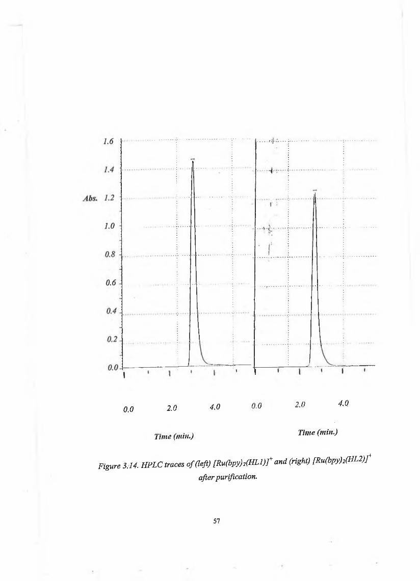
0.0 2.0 4.0 0.0 2.0 4.0
Time (min.) Time (min.)
Figure 3.14. HPLC traces o f (left) [Ru(bpy)2(H L l) f and (right) [R u(bpy)2( H L 2 ) f after purification.
57

!
27éT " " 7.5- ™(pH
-3& g l
5 ?!~ t j —"T T~ts
S\
_________________I
90 8 0ippm)
er* ine»T 1/
- L J
75 7.0
Figure 3.15. 'H-NMR spectra oJ lh L l (top) and lhL2 (bottoni) obtained in DMSO-d().
58

The ]H-NMR spectra of the two ligands are similar as expected from their similar structure. The protons on the phenol ring have very similar shifts in the two compounds; they are too distant from the pyridine/pyrazine ring to be affected.In both ligands the H4" and H6" protons produce a signal composed of respectively a triplet and a doublet at around 7 ppm; the H3" proton produces a doublet signal at around 8 ppm and the H5" proton produces a triplet signal at 7.4 ppm. The protons of the pyridine/pyrazine rings exhibit some difference in their signals. The H6 proton in both ligands have a very similar shift as well (8.75 ppm). The H3 and H5 protons experience a large downfield shift (more than 1 ppm) in the pyrazyl ligand, induced by the adjacent nitrogen. The H3 proton in the pyrazyl ligand is easily recognised because it is the only singlet signal, at 9.38 ppm. The H proton in the pyridyl ligand produces a doublet signal at 8.2 ppm. The H5 proton in the pyrazyl ligand produces a signal at 8.8 ppm versus a signal at 7.35 ppm in the pyridyl ligand.
Complexes
[Ru(bpy)2(H L l)]+
From the elemental analysis and pKa studies, we can see that the phenol ring is protonated and the triazole ring is not protonated.Figure 3.16 shows the XH-NMR spectrum of [Ru(bpy)2(HLl)]+.The protons of the pyridyl and phenol ring have shifts similar to those of the corresponding ligand, except for the H6 proton which experiences the largest shift on coordination to the Ru(bpy)2 entity, (due to interaction with the adjacent pyridyl ring). This behaviour is typical of coordinated pyridines41 as a result of diamagnetic anisotropic interaction of the H6 proton with the adjacent pyridyl ring.The ligand protons could be assigned individually. Bipyridyl resonances could not be assigned to individual rings but were assigned by groups of protons (see section 3.2.1. in the experimental methods part). The NMR spectrum and the X-ray analysis confirm the N,N-coordination of the ruthenium unit to the ligand.
59

|Ru(bpy)2(HL2)]+
As for [Ru(bpy)2(HLl)]+ the protons of the pyrazyl and phenol rings exhibit shifts similar to those of the corresponding ligand, except for the H6 proton which experiences a 1.1 ppm upfield shift. The structure of this complex has been confirmed by a 2D- COSY NMR spectrum, shown in figure 3.17. The protons of the phenol and pyrazine rings could be assigned individually. The H3 proton produces a singlet at 9.3 ppm on the 'H-NMR spectrum. The H5 and H6 protons interact with each other, producing the two doublet signals at 8.3 and 7.65 ppm. The H4” and H6” protons (multiplet at 6.9 ppm) both interact with the H5” proton (triplet at 7.2 ppm). The H4” proton interacts with H3” (7.9 ppm) as well.The metal ion can potentially bind the triazole ring in two different positions, N1’ or N4’. To determine whether it is N1’ or N4’ bound, its spectrum was compared to [Ru(bpy)2(HLl)]+which has been studied by X-ray spectroscopy and shown to be N 1’ bound2. The biggest shift in the phenol ring on coordination to the Ru(bpy)2 entity is experienced by the H5” proton, and is only a 0.41 ppm upfield shift.Similarly, in [Ru(bpy)2(HL2)]+ the biggest shift in the phenol ring on coordination to the Ru(bpy)2 entity is experienced by the H5” proton, and is a 0.2 ppm upfield shift. If the Ru(bpy)2 was N4’ bound, the shifts in the phenol ring would be much larger due to steric hindrance between the phenol ring and the adjacent bipyridyl groups. It has been observed in smaller complexes such as [Ru(bpy)2(pdtr)]4 that a 0.5 ppm shift arises when it is N4’ bound36 (see structure in figure 3.13), even though the pendent group is only a methyl compared to a phenol ring. This suggests that [Ru(bpy)2(HL2)]+ is formed exclusively in the N1 ’ bound structure. It has been observed for other complexes of this type, that when the pendent group to the pyridyltriazole or pyrazyltriazole is an aryl group, the N4’ bound form is not present due to steric hindrance. This is the case of [Ru(bpy)2(bpt)]+, shown on figure 3.18.10
60
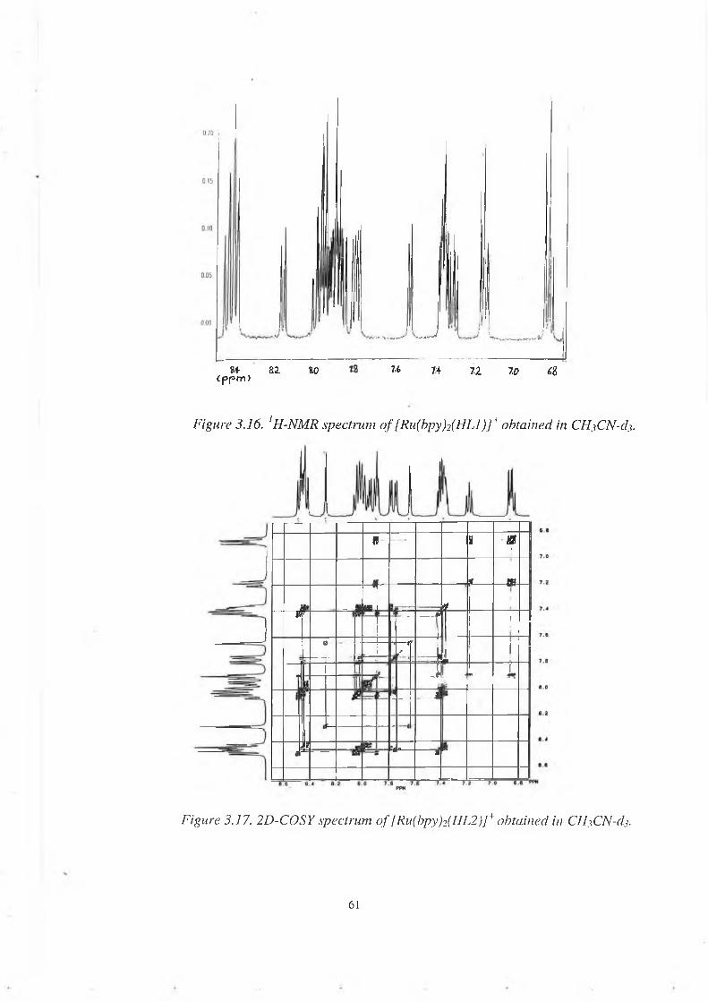
- -V- —■' —+•—^at a i iO 7.6 74 7.2 70 ¿2
ipjom)
Figure 3.16. 1H-NMR spectrum o f [RufbpyfefHLl)]+ obtained in CHjCN-dj.
9 ■— H &1f 0?
* MR- — 4 \*r I **
___ j.!tj
1a ■*—1
-|i i
ft 1
1 1 J----m
r 1----- 11 1__ t ___1
?r «« :8
Figure 3.17. 2D-COSY spectrum o f [Ru(bpy)2(HL2 )]+ obtained in CHjCN-dj.
6 1
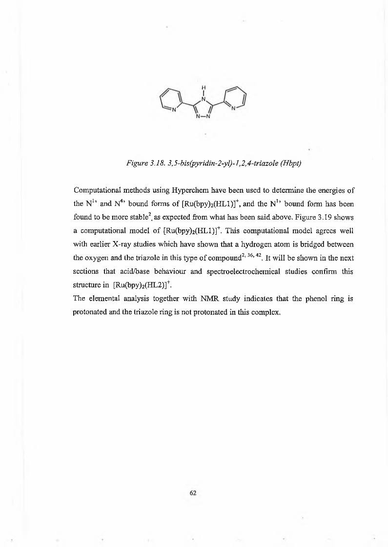
Figure 3.18. 3,5-bis(pyridin-2-yl)-l,2,4-triazole (Hbpt)
Computational methods using Hyperchem have been used to determine the energies of the N1’ and N4’ bound forms of [Ru(bpy)2(HLl)]+, and the N1’ bound form has been found to be more stable2, as expected from what has been said above. Figure 3.19 shows a computational model of [Ru(bpy)2(HLl)]+. This computational model agrees well with earlier X-ray studies which have shown that a hydrogen atom is bridged between the oxygen and the triazole in this type of compound2,36,42. It will be shown in the next sections that acid/base behaviour and spectroelectrochemical studies confirm this structure in [Ru(bpy)2(HL2)]+.The elemental analysis together with NMR study indicates that the phenol ring is protonated and the triazole ring is not protonated in this complex.
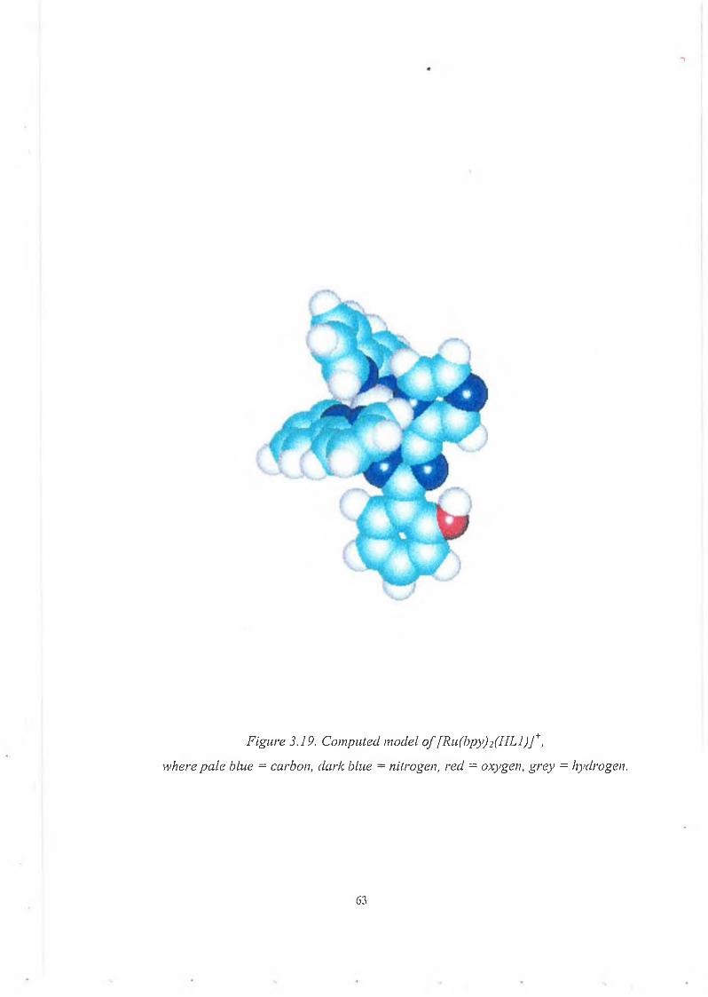
Figure 3.19. Computed model o f [Ru(bpy)2(H L l) f , where pale blue = carbon, dark blue = nitrogen, red = oxygen, grey = hydrogen.
63
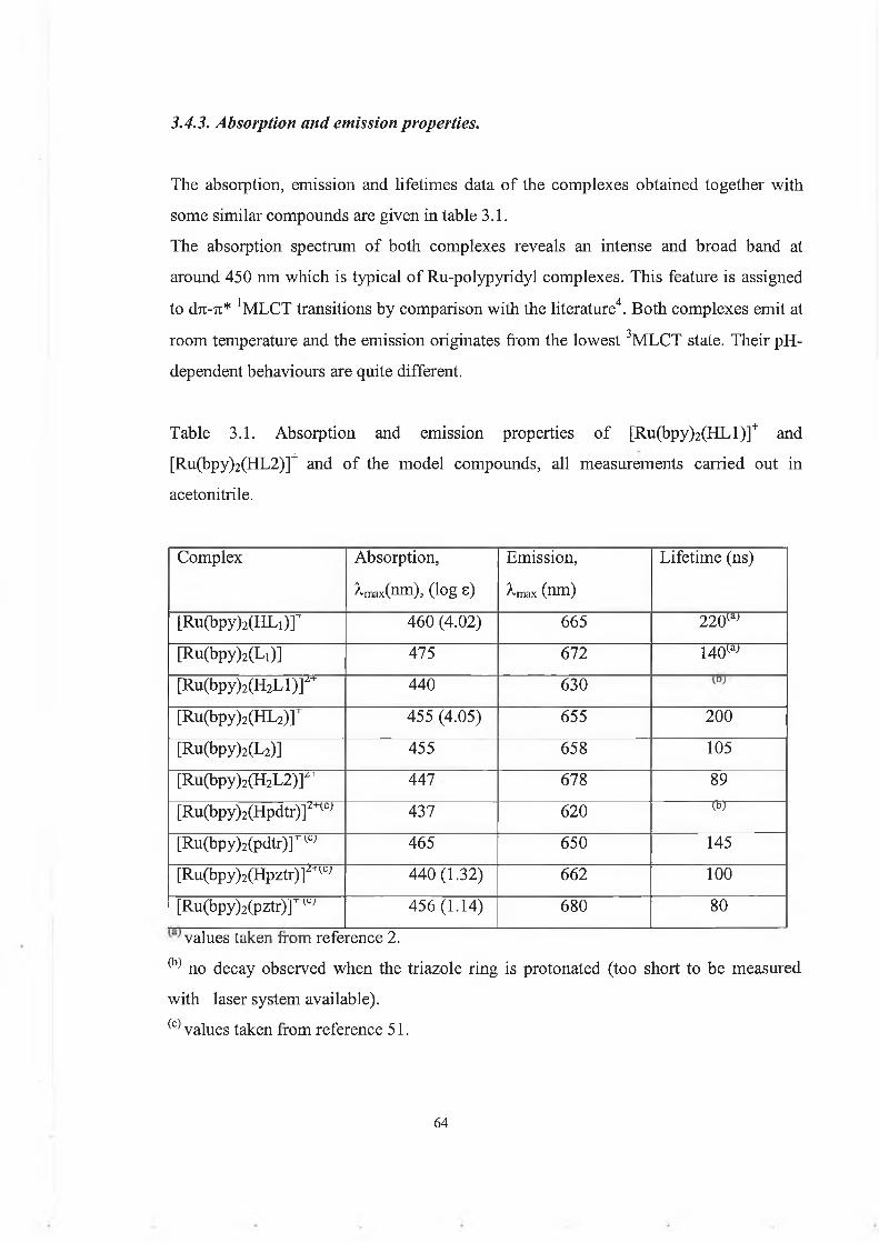
3.4.3. Absorption and emission properties.
The absorption, emission and lifetimes data of the complexes obtained together with some similar compounds are given in table 3.1.The absorption spectrum of both complexes reveals an intense and broad band at around 450 nm which is typical of Ru-polypyridyl complexes. This feature is assigned to d7i-7t* 'MLCT transitions by comparison with the literature4. Both complexes emit at room temperature and the emission originates from the lowest 3MLCT state. Their pH- dependent behaviours are quite different.
Table 3.1. Absorption and emission properties of [Ru(bpy)2(HLl)]+ and [Ru(bpy)2(HL2)]+ and of the model compounds, all measurements carried out in acetonitrile.
Complex Absorption, Àmaxtnm), (log e)
Emission, -max (nm)
Lifetime (ns)
[Ru(bpy)2(HL1)]T 460 (4.02) 665 220w[Ru(bpy)2(Li)] 475 672 14QW[Ru(bpy)2(H2L l ) r 440 630[Ru(bpy)2(HL2)]"r 455 (4.05) 655 200[Ru(bpy)2(L2)] 455 658 105[Ru(bpy)2(H2L 2 ) r 447 678 89[Ru(bpy)2(Hpdtr)]2nc; 437 620 (b)[Ru(bpy)2(pdtr)rw 465 650 145[Ru(bpy)2(Hpztr)]2+w 440 (1.32) 662 100[Ru(bpy)2(pztr)rw 456(1.14) 680 80values taken from reference 2.
^ no decay observed when the triazole ring is protonated (too short to be measured with laser system available).(c) values taken from reference 51.
64

In the case of [Ru(bpy)2(HLl)]+, the lowest excited state involve a transition from the metal to the bpy ligands. The MLCT band at 460 nm is blue-shifted to 440 nm on protonation of the triazole ring. On protonation of the ligand less electron density is present at the metal, and the filled dxc orbital is stabilised, increasing the d7i-7i* energy difference, resulting in this blue shift. This shift is reflected in the emission spectra. The intensity of emission decreases on protonation of the triazole. This is again a result of lower o-donation from the ligand. The ligand field splitting is decreased with lower a- donation, resulting in thermal population of the eg* (3MC) and faster radiationless decay. In the case of [Ru(bpy)2(HL2)]+, the absorption maximum of the MLCT band at 455nm is very slightly blue-shifted (<10 nm) on protonation of the triazole ring and its shape is slightly changed. The same change in the absorbance curve has been reported for [Ru(bpy)2(pztr)]+. It is explained36,46 by a combination of two effects. When the triazole is protonated, both the n* orbital of the pyrazyltriazole and the t2g orbital of the metal centre are lowered on protonation of the triazole, resulting in a very small change in the dTt-Tt* energy difference. The maximum wavelength of the emission spectrum (655nm) is not affected by deprotonation of the phenol, meaning that this moiety is not directly involved in the charge transfer excited state. On protonation of the triazole the emission maximum is red-shifted by 20 nm from 655 nm to 678 nm. Protonation of the triazole causes a stabilisation of the Ru-t2g level. So this red shift means that the emitting 3MLCT level (which is thought to be H2L2-based from the acid/base chemistry, see section 3.4.4) is stabilised slightly more than the Ru-t2g level on protonation of the triazole. It is interesting to compare this behaviour with that of [Ru(bpy)2(pztr)]+, which shows a 20 nm blue shift in the emission spectrum on protonation of the triazole.36,46 When the triazole is deprotonated in [Ru(bpy)2(pztr)]+, the emission energy maximum is at 670 nm and the LUMO is bpy-based. So the emission originates from the triplet Ru —> bpy charge transfer state. When the triazole is protonated, both the Ru-t2g and the tc* pyrazyltriazole are stabilised, and the n* pyrazyltriazole becomes the LUMO. The emission now originates from the Ru3+ —> Hpztr charge transfer state. So the location of the excited state switches from bpy to Hpztr on protonation of the triazole ring.
65
The excited state lifetime of [Ru(bpy)2(HLl)]+ decreases when the phenol is deprotonated. This is due to the quenching of the 3MLCT excited state by the phenolate. 3 * * "I- *The MLCT lifetime of [Ru(bpy)2(HL2)J decreases as well on deprotonation of the phenol. It is probably due to an electron transfer from the phenolate to the Ru unit, as in the case of [Ru(bpy)2(HLl)]+, but this should be further investigated.Protonation of [Ru(bpy)2(HL2)]+ decreases its lifetime. This is due to a lower cr- donation from the ligand, resulting in thermal population of the 3MC states.
3.4.4. Acid/base behaviour.
Acid-base behaviour of this type of compound (containing a triazole) is an important issue. Protonation/deprotonation of the triazole moiety considerably affects the electronic distribution of the complex, by altering the a-donor and 7t-acceptor properties of the ligand. The photophysics of the complex is also affected by those properties. In Ru-polypyridyl complexes the Ru-N link is mainly a in nature, but is stabilised by backbonding between t2g and n* of metal and ligand. Determination of pKa of ligand and complex gives information about the a-donor and 7i-acceptor properties of the ligand and about the extent of backbonding from the metal to the ligand. Determination of pKa and pKa* of the complex is useful in the understanding of the excited state behaviour of the complex. It helps to determine the location of the excited state. If the pKa* of one moiety is lower than its pKa in the ground state, this moiety is not directly involved in the electron transfer of the excited state.41 The metal is oxidised and transfers one of its electrons to an acceptor moiety, while the spectator ligand gives some of its electron density to the metal to try to restore the initial state of electron density of the metal. As a result the donor moiety is more acidic in the excited state than in the ground state. If the excited state pKa* of a moiety is higher than its ground state pKa, this moiety is expected to be directly involved in the excited state charge redistribution. The metal is excited and transfers one electron to that moiety in question, which so has more electron density and becomes more basic.41 So the determination of pKa* and pKa is very useful in the attribution of the excited state
66

charge transfer. Two classes of ligands have been observed so far. The first class of ligands (La) have stronger ^-acceptor and weaker a-donor properties than 2,2’- bipyridine (bpy), causing the emission processes to be La-based in the mixed-ligand complex [Ru(bpy)2(La)]. Examples of this type of ligand are bipyrazines, biquinolines.43 5 The second class of ligands (Lb) have weaker n-acceptor and stronger a-donor properties than bpy. The emission is now bpy-based. An example of such a ligand is the pyridyltriazole type of ligand, in which protonation/deprotonation of the triazole ring affects the properties of the complex but not the lowest 71* level, which is
n/rbpy-based in all cases. An interesting combination of those two classes of ligands is the pyrazyltriazole type of ligand, which combines strong Ti-acceptor properties in the pyrazyl ring61 and strong a-donor properties in the triazole ring. It has been shown that for Ru(bpy)2 complexes containing such type of ligand, the emitting state can be switched from bpy-based to pyrazyltriazole-based by protonation of the triazole ring.36, 46, 47 So the photophysics of such complexes can be tuned by altering the state of protonation of the triazole.50 Acid-base behaviour of the phenol moiety is also important because the phenolate is a good electron donor.40 And it could be involved in an electron transfer from the phenolate moiety to the Ru centre.The experimental details used to determine the acid/base properties of the compounds both in the ground state and excited sate are described in the experimental section.There are two methods of determining the excited state pKa* of a complex. The first one consists of recording emission spectra in the interesting pH range, and plotting a curve of the percentage change in emission intensity vs pH. The inflexion point gives pH; which is not the real pKa* value, because it needs to be corrected for the different lifetimes of the protonated ( t h b ) and deprotonated ( t b - ) complexes, according to equation 3.1. pKa* = pHj + log^ne/to-) (3.1)
• 4RThis approach is based on a kinetic model developed by Ireland and Wyatt.A different approach is based on a calculation from the ground state pKa and the E°'° spectroscopic values. It is more theoretical and less precise, because the E°'° for vb- and vhb are difficult to determine with precision and small errors in these values lead to important ones in pKa*.49 pKa* is given by the equation 3.2.
67
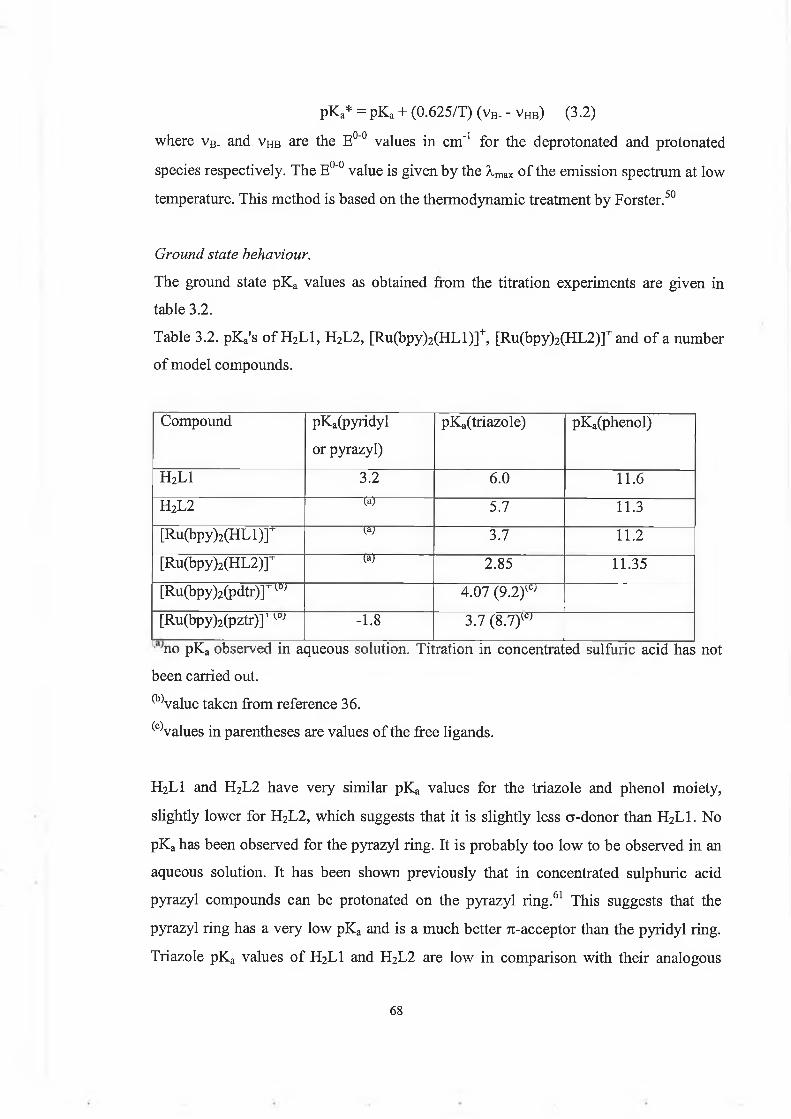
pKa* = pKa + (0.625/T) (vB. - Vhb) (3.2) where vB. and vhb are the E°'° values in cm"1 for the deprotonated and protonated species respectively. The E0"0 value is given by the A,max of the emission spectrum at low temperature. This method is based on the thermodynamic treatment by Forster.50
Ground state behaviour.The ground state pKa values as obtained from the titration experiments are given in table 3.2.Table 3.2. pKa's of H2L1, H2L2, [Ru(bpy)2(HLl)]+, [Ru(bpy)2(HL2)]+and of a number of model compounds.
Compound pKa(pyridyl or pyrazyl)
pKa(triazole) pKa(phenol)
H2L1 3.2 6.0 11.6H2L2 (a) 5.7 11.3[Ru(bpy)2( H L l)r W 3.7 11.2[Ru(bpy)2(H L 2 )r (a) 2.85 11.35[Ru(bpy)2(p d tr)r^ 4.07 (9 .2 )w[Ru(bpy)2(pztr)rw -1.8 3.7 (8.7)wno pKa observed in aqueous solution. Titration in concentrated sulfuric acid has not
been carried out.^ value taken from reference 36.(c)values in parentheses are values of the free ligands.
H2L1 and H2L2 have very similar pKa values for the triazole and phenol moiety, slightly lower for H2L2, which suggests that it is slightly less cr-donor than H2L1. No pKa has been observed for the pyrazyl ring. It is probably too low to be observed in an aqueous solution. It has been shown previously that in concentrated sulphuric acid pyrazyl compounds can be protonated on the pyrazyl ring.61 This suggests that the pyrazyl ring has a very low pKa and is a much better 7i-acceptor than the pyridyl ring. Triazole pKa values of H2L1 and H2L2 are low in comparison with their analogous
68

pyridyltriazole and pyrazyltriazole ligands which have respective pKa values of 9.2 and8.7. This can be explained by the hydrogen bonding between the hydroxyl and the triazole nitrogen N4'. Figure 3.20 shows the absorbance spectra of H2L2 as a function of pH. Figure 3.21 is a plot of the percentage change in absorbance versus pH (see equation in section 3.2.4).In both complexes the pKa of the triazole ring decreases on coordination to the Ru- centre, by 2-3 units. This is because the triazole is an electron rich moiety which gives electron density to the positively charged Run-(bpy)2 entity. The pKa for [Ru(bpy)2(HL2)]+ decreases more than for [Ru(bpy)2(HLl)]+, because the pyrazine ring is more electron accepting than the pyridine ring. The Run-(bpy)2 centre, adjacent to the pyrazine ring, is more positively charged, consequently the triazole gives it more electron density. The pKa’s of [Ru(bpy)2(HLl)]+ and [Ru(bpy)2(HL2)]+ are lower than [Ru(bpy)2(pdtr)]+ and [Ru(bpy)2(pztr)]+ respectively. As for the free ligands, this can be explained by the formation of a proton bridge between the hydroxyl and the triazole nitrogen N4 . Such a bridge reduces the electron density on the triazole and hence the basicity. A model computed (see figure 3.19) for [Ru(bpy)2(HLl)]+ agrees with formation of this bridge. Formation of such bridges has been reported42 for hydroquinonetriazole complexes. The phenol pKa is slightly lower (by ~0.3 units) in the complex than in the free ligand in both cases. This means that the acidity of the phenol ring is not very affected by the presence of the metal unit centre. Absorbance spectra as a function of pH for the triazole protonation of the complexes are shown in figure 3.22. We observe a 20 nm shift from 460 nm to 440 nm for H2LI. This is due to the fact that the triazole ring, on protonation, donates less electron density to the Ru-t2g level, which is then stabilised. So the transition gap between the Ru-t2g and n* of the ligand levels is increased. For H2L2 the blue shift observed on protonation of the triazole ring is only small (10 nm shift from 455 nm to 445 nm) in comparison to that of H2LI. This has been reported for pyrazyltriazole compounds51 and can be explained in this way: the pyrazyl ring is a better 71-acceptor than the pyridyl ring. On protonation of the triazole both the pyrazyl n* and the Ru-t2g orbitals are stabilised, so no significant shift is observed.
69

2 3 0 . 0 30 0 .0Wavelength (uni) 3 7 0 . 0
Wavelength (inn)
Figure 3.20. pH-dependence of the absorption spectra o f IFL2, (top) Deprotonation of the triazole, pH: 4.15, 4.69, 5.05, 5.46, 5.79, 6.11, 6.40, 6.76, 7.23, 7.97.
(bottom) Deprotonation o f the phenol, pii: 9.95, 10.36, 10.68, 10.99, 11.30, ¡1.49,1 / .70, 11.97, 12.36. Compounds measured in Britton-Robinson buffer.
70

pH
Figure 3.21. Percentage change in absortion intensity ofH.2L2 , deprotonation o f thetriazole, pH range from 4.15 to 7.97.
W avelength (nm) nmFigure 3.22. pH-dependence o f the absorption spectra o f [Ru(bpy)2(HLl)]+, pH: 2.88, 3.12, 3.41, 3.77, 4.00, 4.27, 4.59, 5.00, 5.53, 6.16 (left); [Ru(bpy)2(HL2)]+, pH: 1.68, 2.00, 2.22, 2.52, 2.76, 3.06, 3.37, 3.66, 3.85, 4.14 (right). Deprotonation o f the triazole ring. Measured in Britton-Robinson buffer.
71
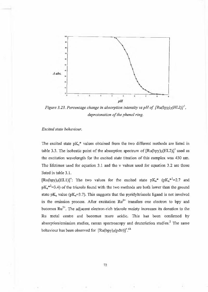
Figure 3.23. Percentage change in absorption intensity vs pH o f [Ru(bpy)2(HL2)]+,deprotonation o f the phenol ring.
Excited state behaviour.
The excited state pKa* values obtained from the two different methods are listed in table 3.3. The isobestic point of the absorption spectrum of [Ru(bpy)2(HL2)]+ used as the excitation wavelength for the excited state titration of this complex was 430 nm. The lifetimes used for equation 3.1 and the v values used for equation 3.2 are those listed in table 3.1.[Ru(bpy)2(HLl)]+: The two values for the excited state pKa* (pKa*1:=2.7 and pKa*2=3.4) of the triazole found with the two methods are both lower than the ground state pKa value (pKa=3.7). This suggests that the pyridyltriazole ligand is not involved■ « • 9+in the emission process. After excitation Ru transfers one electron to bpy and
■I Ibecomes Ru . The adjacent electron-rich triazole moiety increases its donation to the Ru metal centre and becomes more acidic. This has been confirmed by absorption/emission studies, raman spectroscopy and deuteriation studies. The same behaviour has been observed for [Ru(bpy)2(pdtr)]+.64
72

Table 3.3. Excited state pKa* of [Ru(bpy)2(HLl)]+, [Ru(bpy)2(HL2)]+ and of some model compounds.
pHi(pyrazine)
pHi(triazole)
pKa*(triazole)1
pKa*(triazole)2
PH(phenol)
pKa*(phenol)2
[Ru(bpy)2(HL 1)]’’’w 3.3 2.7 3.4 11.1 10.8[Ru(bpy)2(HL2)r 2.25 6.0 5.4 3.95 11.55 11.35[Ru(bpy)2(pdtr)rw 2.7 2.12 3.4[Ru(bpy)2(pztr)rw 2.0 3.9 3.8 2.9values calculated using equation 3.1. values calculated using equation 3.2.
(a)value taken from reference 36.
Emission spectra from [Ru(bpy)2(HL2)]+ have been recorded from pH 1 to pH 13. Three regions are observed. From pH 1 to pH 3 the emission intensity increases, followed by a plateau from pH 3 to pH 4. From pH 4 to pH 7 the emission intensity increases again, followed by another plateau until pH 9. From pH 10 to pH 12 the emission intensity decreases. This suggests that three excited state protonation equilibria are present, which should correspond to the pyrazine, the triazole and the phenol deprotonations. Figure 3.25 shows the emission spectra of [Ru(bpy)2(HL2)]+ as a function of pH. The first step is an intensity increase when going from pH 1 to pH 4. This behaviour is similar to that observed for the pyrazine deprotonation of [Ru(bpy)2(pztr)]+36. Starting from the strongly emitting dication [Ru(bpy)2(Hpztr)]2+the emission intensity decreases rapidly. The pH,(pyrazine) for [Ru(bpy)2(Hpztr)]2+ is 2.0. The samepHj for [Ru(bpy)2(H2L2)]2+is 2.35.Emission maxima and lifetimes for those two protonated pyrazine complexes could not be obtained, because their lifetimes are too short (outside the instrument range), so it was impossible to use equation 3.1 and 3.2 but the pHj values can be used as an estimate. Comparison of the results obtained for [Ru(bpy)2(H2L2)]2+ and [Ru(bpy)2(Hpztr)]2+ suggests that this first step corresponds to the deprotonation of the pyrazine ring in [Ru(bpy)2(H2L2)]2+. As no ground state protonation equilibrium was
73

observed for the pyrazine ring in [Ru(bpy)2(H2L2)] , this suggests that the pyrazine ring is much more basic in the excited state than in the ground state, indicating that the excited state is H2L2-based when the triazole is protonated.36,46The second step, which shows an increase in the emission intensity when varying the pH from 4 to 7, should correspond to the deprotonation of the triazole. The pKa*’s calculated for the second step (pKa*1;=5.4 and pKa*2=3.95) with the two methods are different but they both are higher than the ground state pKa (pKa=2.85) by more than 1 unit. This means that at around pH 4.5 the deprotonated triazole in the ground state becomes protonated in the excited state, suggesting that the excited state is still based on the H2L2 ligand when the triazole is deprotonated. This behaviour is very different from [Ru(bpy)2(pztr)]+, in which deprotonation of the triazole causes a switch from a pztr'-based excited state to a bpy-based excited state.36,46Excited state pKa* measurements are not sufficient in themselves to prove that this interpretation is correct. Low temperature emission studies, Raman and excited sate Raman spectroscopy, and deuteriation studies should be carried out to confirm it.
9+ •
Percentage
emission
change
pH
Figure 3.24. Percentage change in the emission intensity vs pH o f [Ru(bpy)2(HL2)]+,deprotonation o f the phenol.
74

t
Figure 3.25. pH dependence o f the emission spectra o f [Ru(bpy)2(HL2 )]+, (top left) pH from 1.0 to 3.65; (top right) pH from 3.85 to 6.65; (bottom) pH from 10.35 to 12.45.
Measured in Britton-Robinson buffer.
75
The third step shows a decrease in emission intensity on varying the pH from 10 to12.5. This can be explained by deprotonation of the phenol, which then starts quenching the excited state, resulting in this decrease. The excited state pKa* is similar to the ground state pKa, suggesting that the phenol part of the ligand is not directly involved in the emission process.
3.4.5. Redox properties.
Redox properties of ligand and complex are useful in understanding the a-donor and 71- acceptor properties of the ligand. It helps to understand the photophysical behaviour (location of the excited state). In effect a MLCT transition is the transfer of an electron from the HOMO of the metal to the LUMO of the ligand. The same thing happens in electrochemical events where oxidation is the removal of an electron from an orbital and reduction is the injection of an electron into an orbital. So a strong correlation exists between the redox chemistry of Ru(II)polypyridyl complexes and their optical transition properties.5In [Ru(bpy)2(HLi)]+ and [Ru(bpy)2(HL2)]+, there are two possible oxidations, based on the Ru metal and the phenol. Reduction can in principle take place on the two bpy's and on the pyridyl or pyrazyl ring. Redox potentials are given in table 3.4.When the triazole is deprotonated and the phenol protonated, both complexes show two oxidation waves at around 0.9 and 1.4V. With the help of spectroelectrochemistry (see section 3.4.6) the first wave was attributed to the oxidation of the phenol and the second wave was attributed to the oxidation of the Ru centre. This interpretation is different from what was reported for [Ru(bpy)2(HLl)]+ 53, where it was suggested that the metal is oxidised first, followed by the oxidation of the phenol. But spectroelectrochemistry had not been carried out in that case. It has now been carried out on [Ru(bpy)2(HLl)]+ and [Ru(bpy)2(HL2)]+ and shows that the phenol is oxidised before the ruthenium centre.
76

Table 3.4. Redox potentials of [Ru(bpy)2(HLl)]+ and [Ru(bpy)2(HL2)]+ in acetonitrile, 0.1M TEATFB, values in Volt versus SCE.
Complex Phenoloxidation
Ru /Ru oxidation
Reduction
[Ru(bpy)2(H L ,)r 0.9 1.4 -1.30 -1.55[Ru(bpy)2( L , ) r 0.6 1.1 -1.46 -1.71[Ru(bpy)2(HL2) r 1.0 1.5 -0.8[Ru(bpy)2(L2)] 1.5 -1.2[Ru(bpy)2(pd tr)rw 0.83 -1.47 -1.72 -2.25[Ru(bpy)2(p z tr)r^ 0.95 -1.44 -1.66 -1.96Ru(bpy)32+ ibj 1.26 -1.35 -1.55;Values taken from reference 2.
^Values taken from reference 36.
The oxidation potentials of the Ru centre in [Ru(bpy)2(HLl)]+ and [Ru(bpy)2(HL2)]+ are much higher than those in [Ru(bpy)2(pdtr)]+ and [Ru(bpy)2(pztr)]+. This is explained by assuming that oxidation of the phenol causes a proton transfer from the phenol to the triazole (see section 3.4.6). The triazole becomes a weaker a-donor, resulting in a more electropositive Ru centre.[Ru(bpy)2(HLl)]+ showed very clear and reversible waves. This was not the case of [Ru(bpy)2(HL2)]+ which showed weak and quite irreversible peaks. In acetonitrile the first wave for [Ru(bpy)2(HL2)]+ at 1.0V is irreversible and occurs only in the first cycle. But it has been checked by spectroelectrochemistry that an oxidation really occurs at this potential. There might be some problems of polymerisation on the electrode surface with this compound because all the measurements were carried out in the same conditions as for [Ru(bpy)2(HLl)]+ which showed clear electrochemistry, but all of them were weak and irreversible in the case of [Ru(bpy)2(HL2)]+.
77
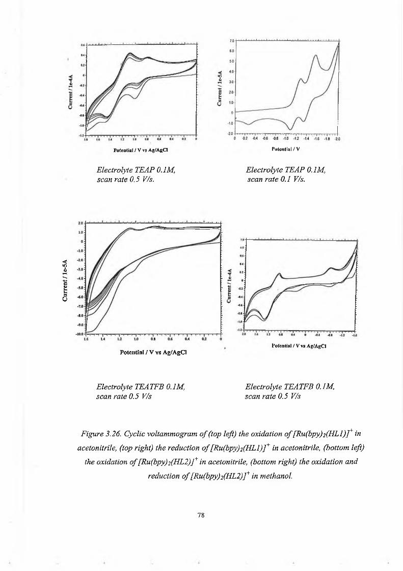
Curr
ent
/ le-
5A
Potential / V vs Ag/AgCI Potential / V
Electrolyte TEAP 0.1M, scan rate 0.5 V/s.
Electrolyte TEAP 0.1M, scan rate 0.1 V/s.
Potential / V vs Ag/AgCIPotential / V vs Ag/AgCI
Electrolyte TEATFB 0.1M, Electrolyte TEATFB 0.1M,scan rate 0.5 V/s scan rate 0.5 V/s
Figure 3.26. Cyclic voltammogram o f (top left) the oxidation o f [Ru(bpy)2(HLl)]+ in acetonitrile, (top right) the reduction o f [Ru(bpy)2(HLl)]+ in acetonitrile, (bottom left)
the oxidation o f [Ru(bpy)2(HL2)]+ in acetonitrile, (bottom right) the oxidation and reduction o f [Ru(bpy)2(HL2)]+ in methanol.
78
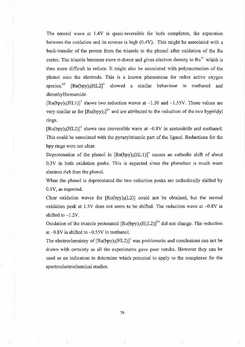
The second wave at 1.4V is quasi-reversible for both complexes, the separation between the oxidation and its reverse is high (0.4V). This might be associated with a back-transfer of the proton from the triazole to the phenol after oxidation of the Ru
• ■ 3+ •centre. The triazole becomes more a-donor and gives electron density to Ru which is then more difficult to reduce. It might also be associated with polymerisation of the phenol onto the electrode. This is a known phenomena for redox active oxygen species.62 [Ru(bpy)2(HL2]+ showed a similar behaviour in methanol and dimethylformamide.[Ru(bpy)2(HLl)]+ shows two reduction waves at —1.30 and —1.55V. Those values are very similar as for [Ru(bpy)3]2+ and are attributed to the reduction of the two bypiridyl rings.[Ru(bpy)2(HL2)]+ shows one irreversible wave at -0.8V in acetonitrile and methanol. This could be associated with the pyrazyltriazole part of the ligand. Reductions for the bpy rings were not clear.Deprotonation of the phenol in [Ru(bpy)2(HLl)]+ causes an cathodic shift of about 0.3V in both oxidation peaks. This is expected since the phenolate is much more electron rich than the phenol.When the phenol is deprotonated the two reduction peaks are cathodically shifted by 0.1V, as expected.Clear oxidation waves for [Ru(bpy)2(L2)] could not be obtained, but the second oxidation peak at 1.5V does not seem to be shifted. The reduction wave at -0.8V is shifted to —1.2V.Oxidation of the triazole protonated [Ru(bpy)2(H2L2)]2+ did not change. The reduction at -0.8V is shifted to -0.55V in methanol.The electrochemistry of [Ru(bpy)2(HL2)]+ was problematic and conclusions can not be drawn with certainty as all the experiments gave poor results. However they can be used as an indication to determine which potential to apply to the complexes for the spectroelectrochemical studies.
79
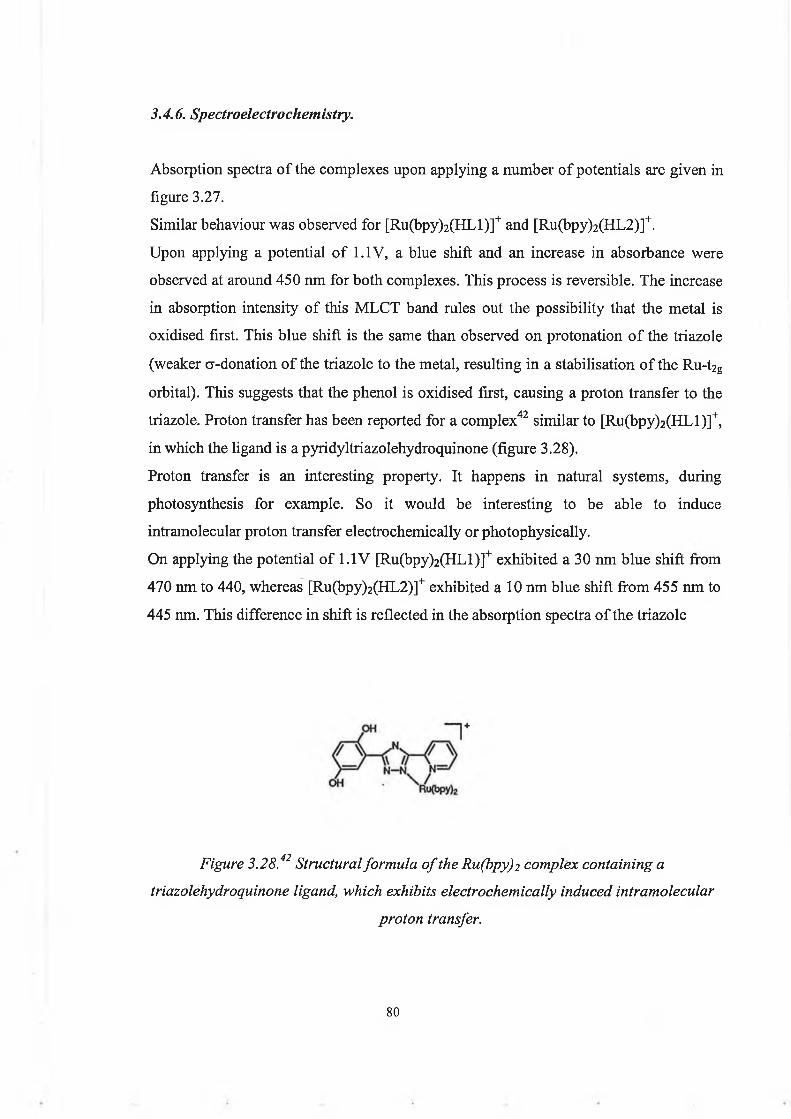
3.4.6. Spectroelectrochemistry.
Absorption spectra of the complexes upon applying a number of potentials are given in figure 3.27.Similar behaviour was observed for [Ru(bpy)2(HLl)]+ and [Ru(bpy)2(HL2)]+.Upon applying a potential of 1.1V, a blue shift and an increase in absorbance were observed at around 450 nm for both complexes. This process is reversible. The increase in absorption intensity of this MLCT band rules out the possibility that the metal is oxidised first. This blue shift is the same than observed on protonation of the triazole (weaker a-donation of the triazole to the metal, resulting in a stabilisation of the Ru-t2g orbital). This suggests that the phenol is oxidised first, causing a proton transfer to the triazole. Proton transfer has been reported for a complex42 similar to [Ru(bpy)2(HLl)]+, in which the ligand is a pyridyltriazolehydroquinone (figure 3.28).Proton transfer is an interesting property. It happens in natural systems, during photosynthesis for example. So it would be interesting to be able to induce intramolecular proton transfer electrochemically or photophysically.On applying the potential of 1.1 V [Ru(bpy)2(HLl)]+ exhibited a 30 nm blue shift from 470 nm to 440, whereas [Ru(bpy)2(HL2)]+ exhibited a 10 nm blue shift from 455 nm to 445 nm. This difference in shift is reflected in the absorption spectra of the triazole
Figure 3.28.42 Structural formula o f the Ru(bpy)2 complex containing a triazolehydroquinone ligand, which exhibits electrochemically induced intramolecular
proton transfer.
80

Figure 3.27. Spectroelectrochemistry: Change in the absorption spectra o f (top left) [Ru(bpy)2(HLl)]+ when applying 1 .IV, (top right) [Ru(bpy)i(HLl)]+ when applying
1.6V, (bottom) [Ru(bpy)2(HL2)]+ when applying 1.1V.
8 1
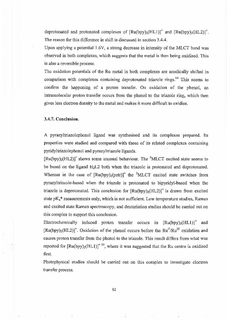
deprotonated and protonated complexes of [Ru(bpy)2(HLl)]+ and [Ru(bpy)2(HL2)]+. The reason for this difference in shift is discussed in section 3.4.4.Upon applying a potential 1.6V, a strong decrease in intensity of the MLCT band was observed in both complexes, which suggests that the metal is then being oxidised. This is also a reversible process.The oxidation potentials of the Ru metal in both complexes are anodically shifted in comparison with complexes containing deprotonated triazole rings.64 This seems to confirm the happening of a proton transfer. On oxidation of the phenol, an intramolecular proton transfer occurs from the phenol to the triazole ring, which then gives less electron density to the metal and makes it more difficult to oxidise.
3.4.7. Conclusion.
A pyrazyltriazolephenol ligand was synthesised and its complexes prepared. Its properties were studied and compared with those of its related complexes containing pyridyltriazolephenol and pyrazyltriazole ligands.[Ru(bpy)2(HL2)]+ shows some unusual behaviour. The 3MLCT excited state seems to be based on the ligand H2L2 both when the triazole is protonated and deprotonated. Whereas in the case of [Ru(bpy)2(pztr)]+ the 3MLCT excited state switches from pyrazyltriazole-based when the triazole is protonated to bipyridyl-based when the triazole is deprotonated. This conclusion for [Ru(bpy)2(HL2)]+ is drawn from excited state pKa* measurements only, which is not sufficient. Low temperature studies, Raman and excited state Raman spectroscopy, and deuteriation studies should be carried out on this complex to support this conclusion.Electrochemically induced proton transfer occurs in [Ru(bpy)2(HLl)]+ and [Ru(bpy)2(HL2)]+. Oxidation of the phenol occurs before the Run/RuUI oxidation and causes proton transfer from the phenol to the triazole. This result differs from what was reported for [Ru(bpy)2(HLl)]+ 53, where it was suggested that the Ru centre is oxidised first.Photophysical studies should be carried out on this complex to investigate electron transfer process.
82
3.5. Dinuclear complexes.
3.5.1. General.
Dinuclear complexes are of special interest because electron and/or energy transferbetween the two metal units may occur if the complex is not symmetrical (two differentmetals on a symmetrical ligand or two identical metals on a non-symmetrical ligand).Electron transfer can also take place in a symmetrical mixed-valence complex. In thiscase electron hopping from M(II) to M(III) in dinuclear Ruthenium and Osmium
i tcomplexes can be detected in the near-infrared absorption spectra and is called the intervalence transition (IT). Hush developed a theory from observing such systems54, which is mentioned in section 2.2.2. This theory states that the energy of the IT transition consists of an inner-sphere contribution and an outer-sphere contribution. It is possible to determine the extent of electron delocalisation (a) from the properties of the IT band: is the system better described as valence-trapped or delocalised?The metal-metal interaction in dinuclear complexes can be classified into three types according to Robbin and Day55. The interaction between the two metals can be negligible (the complex is localised and acts as two mononuclear complexes), weak (the complex is mainly localised but exhibits some new properties associated with the small interaction), strong (the complex is delocalised and its properties are completely different from the mononuclear complexes). This was explained in more detail in section 2.2.2.The design of useful dinuclear complexes requires some conditions. The bridging ligand should allow efficient communication between the metal centres without creating delocalisation. And it should induce a strong ligand field splitting (which prevent photoinstability). In general, strong 7t-acceptor bridging ligands will contribute to better 7i;-orbital overlap between metals, and strong a-donor bridging ligands will create better photostability and luminescence (3MC levels non-accessible). So a compromise must be met for the choice of the bridging ligand.
83

Triazolate bridges are an interesting solution because they are are good a-donor ligands and their negative charge has been found to support good electron communication between metals.58,64In our system the two metal units have different coordination sites. One metal is coordinated to the triazole via N,N site and the second metal is 0,N-coordinated. This is an interesting point because a potential problem in dinuclear complexes containing a negative bridging ligand is the following. On coordination of the second metal the electron donation from the negative bridge has to be shared between the two metals and so the donation to each metal is decreased resulting in stabilisation of the metal t2g, making the MC levels more accessible. The phenolate is a good a-donor so it will donate electron density to the 0,N-coordinated metal, allowing the triazole to give most of its electron density to the N,N-coordinated metal. This might result in a good photostability.
3.5.2. Synthesis and structural characterisation.
[(Ru(bpy)2)2(Ll)](PFe)2 and [(Ru(bpy)2)2(L2)](PF6)2 were synthesised as described in the experimental section. The NjN1 ’-coordinated mononuclear complex was used as a starting material so that no coordinations isomers would form. The products obtained were both about 95% pure by HPLC analysis after recrystallisation in acetone/water. [(Ru(bpy)2)2(L2)] (PF6)2 was furher purified using acetonitrile on an alumina column. Further purification of [(Ru(bpy)2)2(Ll)](PFe)2 was tried on an alumina column with various combinations of solvent and salt, but these attempts were unsuccessful. Elemental analyses for both complexes confirm the structures proposed (see experimental section). Figure 3.30 shows the HPLC analyses of[(Ru(bpy)2)2(Ll)](PFe)2 and [(Ru(bpy)2)2(L2)](PF6)2- Figure 3.29 shows the models computed with Hyperchem of [Ru(bpy)2(HLl)]+and [(Ru(bpy)2)2(Ll)]2+.
84

Figure 3.29. Computed model o f [Ru(bpy)2(HL1)]+ (top) and [(Ru(bpy)2) j(L I)]2+(bottom) where pale blue = carbon, dark blue = nitrogen, red
oxygen, grey = hydrogen
85

Figure 3.30. HPLC traces o f [(Ru(bpy)2) 2(Ll)](PF6) 2 (left) and [(Ru(bpy)2) 2(L2)](PF6) 2(right) after purification.
The elemental C, H, N analyses for [(Ru(bpy)2)2(Ll)](PF6)2and [(Ru(bpy)2)2(L2)](PF6)2 correspond to the calculated values. They suggest that both the phenol and the triazole rings are deprotonated in both complexes. And there are two PF6" anions.Proton NMR spectra of [(Ru(bpy)2)2(Ll)](PFe)2 and [(Ru(bpy)2)2(L2)](PF6)2 are shown in figure 3.31 and 3.32. The first NMR spectra of [(Ru(bpy)2)2(L 1)](PF6)2 and [(Ru(bpy)2)2(L2)](PF6)2 were obtained after recrystallisation in acetone/water. The signals between 6 and 7 ppm, and around 9.2 ppm are broad for both complexes. Broad peaks can have three different causes: 1) hindered rotation,
2) a viscous solvent,3) presence of a radical.
The solvent used was acetonitrile so there should not be any problems of viscosity. A high temperature (60°C) NMR spectrum was recorded, as well as a spectrum of the complex in presence of sodium borohydride (NaBFL*), which is a reducing agent. The broad peaks disappeared in both cases. This possibly suggests the absence of hindrance in those complexes. So it could be due to the presence of a small amount of thermostable radical.
86

(fwFigure 3.31. 1H-NMR spectra o f [(Ru(bpy)2)2(L2 )](PFo)2 in acetonitrile-dj (top),
[(Ru(bpy)2)2(L2 )](PFc,)2 in acetomtrile-dj containing NaBH4 (bottom).
87

bI
- 1
D . i il • v ; ir~- ' lO ki , J U _tn n ■«a-
_____I . Auo CDO 'OJ I I S o | a ! .o or-~ I : to 5! cn <
saz>0 S ’"V-
CDt o i r->O Cn1| lO ' '— | rw ° l K i , ;l — - £0 cn 101
't--r * rBjd T as ! r ' 8,0 T ■ ¿-1— *r- t '
1S--I)----1
Wf ■ 1 1 >"65 6.0
Figure 3.32. 1H-NMR spectra o f [(Ru(bpy)2h (L l )](PF6h in acetoiutrile-dj (lop), [(Ru(bpy)2h(Ll)](PF (,)2 in acetonitrile-dj containing NaBH^bottom).
88

N— N
Figure 3.33. Strutural formulas ofHbpt (left) and Hbpzt (right).
Assignment of individual peaks is difficult to make because the complex is asymmetric, so there are many individual signals. ^-N M R of the deuterated analogue would be helpful but this compound was not synthesised due to lack of time. However comparison of the 'H-NMR spectra of [(Ru(bpy)2)2(Ll)](PF6)2 and [(Ru(bpy)2)2(L2)](PF6)2 with those of the mononuclear complexes, and with those of the dinuclear complexes ofHbpt and Hbpzt36,56 (figure 3.33) suggests that the protons in the vicinity of the phenol moiety produce broader signals. In the case of [(Ru(bpy)2)2(L2)](PF6)2 only the signals in the regions mentioned above are broadened, the rest of the spectrum looks very similar with or without reducing agent. By comparing the signals between 6.0 and 7.2 ppm in the mononuclear and dinuclear complexes and considering that [(Ru(bpy)2)2(bpzt)]3+ shows no signal between 6.0 and 7.0 ppm, it is concluded that the broadened peaks correspond to H3”, H4” and H5” of the phenol ring. The broad peak at 9.2 ppm could correspond to H3 of the pyrazine ring, but this is only a suggestion because not enough data are available to assign the signals. [(Ru(bpy)2)2(Ll)](PFe)2 shows a similar behaviour, except that the signals in the whole spectrum seem slightly broadened. To assign which part of the molecule is a radical, it should be borne in mind that a radical influences all its surroundings, so it is expected that the signals of all the protons around the radical will be broadened in the ^-N M R spectrum. If Ru was a radical the bpy protons would be influenced by it and their
89

signals broadened in the 'H-NMR spectrum. But only the signals of the ligand protons are broadened, so a possible explanation would be that the oxygen is a radical. This should be checked by EPR studies.From the ^-N M R of the complex it seems likely that there are four optical isomers. Coordination isomers may be ruled out because the starting material consisted of the NjN1'-coordinated mononuclear complex only. Those isomers are not separated on HPLC and do not seem to have different absorption, emission or electrochemical properties. They could be optical isomers (different relative orientation of the bpy ligands). Such behaviour has been reported for dinuclear bpt complexes.56 X-ray analysis would be necessary to confirm the structure in large compounds such as those ones.
3.5.3. Absorption and emission properties.
Absorption and emission data are listed in table 3.5. Figure 3.34 shows the absorption spectra of the mononuclear and dinuclear complexes of H2L2 . Figure 3.35 shows the emission spectra of the mononuclear and dinuclear complexes of H2L2 in neutral and acidic solution.Upon going from a mononuclear to a dinuclear complex two different behaviours have been observed depending on the type of ligand. They are called class a if the excited state is based on the bridging ligand, class b if the bridging ligand is not directly involved in the excited state. Class a ligands exhibit a shift to lower energy in the absorption spectra because the 71* level is stabilised. Class b ligands exhibit a blue shift in the absorption spectra because the bridging ligand becomes a weaker a-donor and the d orbital of the metal is stabilised .The absorption maxima of [(Ru(bpy)2)2(Ll)]2+ and [(Ru(bpy)2)2(L2)]2+ are not significantly shifted in comparison with the mononuclear complexes. This means that the electron density on the triazolate ligand is not considerably reduced upon coordination to the second metal. This can be associated with the fact that the phenolate is a good electron donor and the (0,N)-coordinated metal is stabilised mostly by the phenolate. The shape of the absorption spectra of the dinuclear complexes is different
90

from the one of the absorption spectra of the mononuclear complexes (see figure 3.34). Both complexes emit weakly in acetonitrile at room temperature. Interestingly the
• • 9-1- •emission of [(Ru(bpy)2)2(Ll)] is blue-shifited of 30 nm compared to its mononuclear analogue, which is consistent with normal changes observed, for example, in bpt mono and dinuclear complexes.59 The emission of [(Ru(bpy)2ML2)]2+ does not exhibit any shift in comparison with the mononuclear complex. This has been observed in bpzt' dinuclear complex and is explained in this way: both the lowest n* of bpzt' and the filled d orbital are lowered, and the energy of the MLCT remains similar because the two effects cancel each other36. From the elemental analysis it is thought that [(Ru(bpy)2)2(Ll)]2+ and [(Ru(bpy)2)2(L2)]2+ contain deprotonated triazole and phenol. Therefore adding base to the solutions of complex should not produce any change in the absorption and emission spectra, this was indeed observed.
Table 3.5. Absorption and emission data, all measurements carried out in acetonitrile.
Absorption, A,max (nm) Emission, X,max (nm) (x, ns)[(Ru(bpy)2)2(Ll)]2T 472 352 640 (108)w[(Ru(bpy)2)2( L 2 ) r 460 363 660 (105)[(Ru(bpy)2)2(L2)]^ in acidic solution.
536 412 736
[Ru(bpy)2(H L l)r 460 665 (220)[Ru(bpy)2(Ll)J 475 672 (140)[Ru(bpy)2(H2L l ) r 440 630[Ru(bpy)2(H L 2 )r 455 655 (200)[Ru(bpy)2(L2)] 455 658 (105)[Ru(bpy)2(H2L 2 ) r 447 678 (90)
^Value taken from reference 2.
91

0 .S751
l i|Ru{bpy ),(H | L2)J,f
[(Ru(bpy)i>j(L2)3ì '
\ j ;(CRu(bpy)2WL2)rin acidic solution.
\ ' / \\ \ \ / w N\
ì x\
\
0 . QOC*-----3 0 0 .0 5 5 0 ,0 W avelcnatrh fnm »
Figure 3.34. Absorption spectra o f [Ru(bpy)%(HL2)J\ ((Ru(bpyhh(L2)]2+ inacetoni! rii e unii ¡(Ru(bpy)2)?(L2 )J2+ in acidic acetan il rile
W avelength (am)Figure 3.35. Emission spectra o f [Ru(bpy)i(HL2)]+, [(Ru(bpyhh(L2j /?+ in acetonitrile
and l(Ru(bpy)2h(L2 )}2+ in acidic acetonitrile.
92
Adding acid may protonate the phenol, the triazole and the pyrazine moieties. In order to know which moieties are protonated on addition of acid, the pKa’s of the complexes should be known and quantitative addition of acid should be done. As the pKa’s of the complexes have not been determined, a small quantity of perchloric acid was added to
2"H •the complex solution. In the case of [(Ru(bpy)2)2(Ll)] the solution went from brown to yellow on addition of perchloric acid, and this change is not reversible. The absorption and emission spectra were recorded. Their maxima are very similar to those of [Ru(bpy)2(H2Ll)]2+, suggesting that the dinuclear complex decomposed to the mononuclear complex on addition of acid. The mononuclear complex is yellow. In the case of [(Ru(bpy)2)2(L2)]2+, the solution went from brown to pink and this is a reversible process. The maxima of the absorption and emission spectra were significantly red-shifted. The absorption maximum was shifted from 460 nm to 536 nm, which corresponds to the absorption of the pyrazine-protonated complex36. The emission maximum was shifted from 656 nm to 736 nm, and the intensity of emission is increased by a factor of 4. This is in the range of a pyrazine-based emission process, but it should be confirmed that this emission process is due to the pyrazine-protonated complex. From what is said above it seems that the pyrazine ring in [Ru(bpy)2(HL2)]+ is protonated on addition of perchloric acid, and this considerably shifts the absorption and emission maxima and increases the intensity of emission. But it is not known with certainty what moieties are protonated so no conclusion can be drawn, but it seems that something occurs on protonation of this complex, this should be studied in more detail.
3.5.4. Electrochemistry.
Redox potentials for the complexes studied are listed in table 3.6.[(Ru(bpy)2)2(Ll)]2+ and [(Ru(bpy)2)2(L2)]2+both exhibit two oxidation waves at about 0.4V and 1.2V vs SCE. Oxidation can in principle take place on the two metals and on the phenol. In the mononuclear complexes the oxidation associated with the phenol was not reversible. In the case of the dinuclear complexes the two oxidation waves are perfectly reversible, which suggest that both are metal based. This is expected since the phenol part of the ligand gives electron density to the (0,N)-coordinated metal, which
93
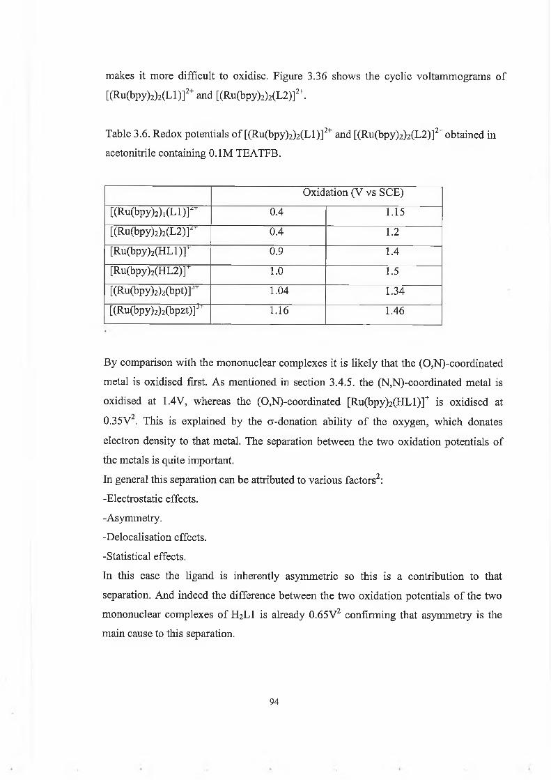
makes it more difficult to oxidise. Figure 3.36 shows the cyclic voltammograms of [(Ru(bpy)2)2(Ll)]2+ and [(Ru(bpy)2)2(L2)]2+.
Table 3.6. Redox potentials of [(Ru(bpy)2)2(Ll)]2+ and [(Ru(bpy)2)2(L2)]2+ obtained in acetonitrile containing 0.1M TEATFB.
Oxidation (V vs SCE)[(Ru(bpy)2) , ( L l ) r 0.4 1.15[(Ru(bpy)2)2( L 2 ) r 0.4 1.2[Ru(bpy)2( H L l) r 0.9 1.4[Ru(bpy)2(H L 2 )r 1.0 1.5[(Ru(bpy)2)2( b p t ) r 1.04 1.34[(Ru(bpy)2)2(bpzt)]3T 1.16 1.46
By comparison with the mononuclear complexes it is likely that the (0,N)-coordinated metal is oxidised first. As mentioned in section 3.4.5. the (N,N)-coordinated metal is oxidised at 1.4V, whereas the (0,N)-coordinated [Ru(bpy)2(HLl)]+ is oxidised at0.35V . This is explained by the a-donation ability of the oxygen, which donates electron density to that metal. The separation between the two oxidation potentials of the metals is quite important.In general this separation can be attributed to various factors2:-Electrostatic effects.-Asymmetry.-Delocalisation effects.-Statistical effects.In this case the ligand is inherently asymmetric so this is a contribution to that separation. And indeed the difference between the two oxidation potentials of the two mononuclear complexes of H2L1 is already 0.65V2 confirming that asymmetry is the main cause to this separation.
94

Curre
nt / le
-5A
Curre
nt / le
-5A
Potential / V vs SCE
Figure 3.36. Cyclic voltammogram o f [(Ru(bpy)2) 2(Ll)]2+ (top) and [(Ru(bpy)2)2(L2)]2+ (bottom), electrolyte TEATFB 0.1M, scan rate 0.1 V/s.
95

The intervalence band properties have not been investigated, it would be useful to study them in order to know more about the degree of delocalisation in those two complexes. The oxidation potentials of [(Ru(bpy)2)2(Ll)]2+ and [(Ru(bpy)2)2(L2)]2+are cathodically shifted in comparison with those of [(Ru(bpy)2)2(bpt)]3+ and [(Ru(bpy)2)2(bpzt)]3+, especially the first one which is shifted of 0.6V. This is explained by the a-donation of the phenol, which makes the (0,N)-coordinated metal much easier to oxidise. [(Ru(bpy)2)2(Ll)]2+ exhibit reduction processes in the range —1.4 and -1.8V, but they are not clearly defined. [(Ru(bpy)2)2(L2)]2+ does not show any clearly defined reduction process either.
3.5.5. Conclusion.
The two dinuclear complexes of H2LI and H2L2 were prepared.The synthesis produced complexes containing a radical, probably located on the oxygen of the bridging ligand. The elemental analysis suggests that both the phenol and the triazole are deprotonated in those complexes. NMR spectra of the deuterated analogues and X-ray analysis would help to confirm the structure.The measurements carried out on the complexes show that the (0,N)-coordinated metal is stabilised by the phenol. This is interesting because the triazole electron density does not decrease significantly on coordination of the second metal.Only few measurements have been carried out on those complexes. To fully understand the photophysical and electrochemical properties of these complexes they have to be studied in more detail.
96

Chapter 4: Summary and suggestions fo r future work.
This project deals with the synthesis, structural characterisation and study of the properties of two phenoltriazole ligands, their (N,N)-coordinated mononuclear complexes and dinuclear complexes, with respect to artificial photosynthesis.An introduction to artificial photosynthesis is given in chapter 2, where the general principles for mimicking photosynthesis are explained. The theoretical aspects necessary to research in this area are covered and the final system aimed for is described.In part 3.1 the synthesis and chatacterisation of some ruthenium polypyridyl complexes are reported.Synthesis and structural characterisation of H2LI, H2L2 and their (N,N)-coordinated mononuclear complexes is described. Only the (N,N'’)-coordinated isomer is formed due to steric hindrance from the phenol ring. The photophysical properties of the complexes can be tuned by altering the state of protonation of the triazole ring. From the acid/base behaviour it is seen that H2L2 is abetter electron acceptor than H2LI. This is because pyrazine is a better electron acceptor than pyridine. This has been reported to considerably affect the photophysical behaviour of [Ru(bpy)2(pdtr)]+ and [Ru(bpy)2(pztr)]+, the compounds used as models in this project. In [Ru(bpy)2(pdtr)]+ the MLCT excited state is based on the bpy ligand regardless of the state of protonation of the triazole. [Ru(bpy)2(HLl)]+ exhibits the same behaviour. Whereas in [Ru(bpy)2(pztr)]+ the 3MLCT excited state is switched from bpy-based to pyrazyltriazole-based on protonation of the triazole. The excited state acid/base behaviour of [Ru(bpy)2(HL2)]+ is unusual and suggests that the 3MLCT excited state is based on the HL2 ligand both when the triazole is protonated and deprotonated. This should be confirmed by a more detailed study of the complex. Spectroelectrochemistry suggests that an electrochemically induced proton transfer from the phenol to the triazole happens in [Ru(bpy)2(HLl)]+ and [Ru(bpy)2(HL2)]+. The complexes should be studied further to investigate electron transfer from the phenolate moiety to the 3MLCT state.
97

The synthesis and characterisation o f the dinuclear complexes is described. Their synthesis produced complexes containing a radical w hich seems to be located on the oxygen atom o f the phenol ring. Electrochemical and absorption/em ission studies show that the phenol stabilises the (0,N)-coordinated metal so the triazole electron density does not decrease significantly on coordination o f the second metal.
98

R e f e r e n c e s
1. Light, chemical change and life: a source book in photochemistry, edited by J.D.Coyle, R.R. Hill and R.R. Roberts.
2. T. Keyes, Ph.D. thesis 1994, Dublin City University.3. W asielewski M.R., Chem Rev. 1992, 92, 435.4. Sauvage J.P., Collin J.P., Chambron J.P., Guillerez S., Coudret C., Balzani V.,
Barigelletti F., De Cola L., Flamigni L.; Chem. Rev. 1994, 94, 993.5. (a) Balzani V., Juris A., Venturi M., Campagna S., Serrani S.; Chem. Rev. 1996,
96, 759. (b) M arcus R.A; Discuss. Faraday soc. 1960, 29, 21. (c) Forster Th.; Discuss. Faraday Soc. 1959, 27, 7. (d) Dexter D.L.; Chem. Phys. 1953, 21, 836.
6. Photochemical conversion and energy storage, edited by John S. Connolly, New York: Academic Press, 1981.
7. Giuffrida G., Calogero G., Ricevuto V., Campagna S.; Inorg. Chem. 1995, 34, 1957.
8. Giuffrida G., Calogero G., Guglielmo G., Ricevuto V., Ciano M., Campagna S.; Inorg. Chem. 1993, 32, 1179.
9. Beley M., Chodorowski-Kimmes S., Collin J.P., Laine P., Launay J.P., Sauvage J.P .;Angew. Chem. Int. Ed. Engl. 1994, 33, 1175.
10. Serrani S., Campagna S., Denti G., Keyes T.E., Vos J.G.; Inorg. Chem. 1996, 35, 4513.
11. De Cola L., Balzani V., Barigettelli F., Flamigni L., Belser P., V on Zelewsky A., Frank M., Vogtle F.; Inorg. Chem. 1993, 32, 5228.
12. Bard A. J., Fox M.; Acc. Chem. Res. 1995, 28, 141.13. El Torki F.M., Schmehl R.H., Reed W.F., J. Chem. Soc., Faraday Trans. I. 1989,
85, 349.14. Shafirovich V.Y., Shilov A.E.; Lsr. J. Chem. 1988, 38, 149.15. Kalyanasandaram K., Borzarello E., Gratzel M.; Helv. Chim. Acta, 1981, 64, 362.16. Borzarello E., Kiwi J., Pelizzetti E., V isca M., Gratzel M.; Nature 1981, 289, 159.
99

17. Amadelli R., Argazzi R., Bignozzi C.A., Scandola F.; J. Am. Chem. Soc. 1990, 112, 7099.
18. Gratzel M.; Acc. Chem. Res. 1981, 14,376.19. Lehn J.-M., Supramoleeular Chemistry, VCH: W einheim, 1995.20. Balzani V, Scandola F.; Supramoleeular Photochemistry Horwood: Chichester,
1991, Ch. 12.21. Credi A., Balzani V., Langford S.J., Stoddart J.F.; J. Am. Chem. Soc. 1997, 119,
2679.22. Asakawa M., Ashton P.R., Ballardini R., Balzani V., Belohradsky M., Gandolfi
M.T., Kocian O., Prodi L., Raymo F.M., Stoddart J.F., Venturi M.; J.Am. Chem. Soc. 1997, 119,302.
23. Balzani V, Gomez-Lopez M., Stoddart J.F., Acc. Chem. Res. 1998, 31, 405.24. Bonhote P., Gogniat E., Tingry S., Barbe C., Vlachopoulos N., Lenzmann F.,
Comte P., Gratzel M.; J. Phys. Chem. B. 1998, 102, 1498.25. Denti G., Campagna S., Serroni S., Ciano M., Balzani V.; J. Am. Chem. Soc. 1992,
114, 2944.26. Belser P., von Zelewsky A., Frank M., Seel C., Vogtle F., De Cola L., Barigelletti
F., Balzani V.; J. Am. Chem. Soc. 1993, 115, 4076.27. Barigelletti F., Famigni L., Balzani V., Collin J.-P., Sauvage J.-P., Sour A.,
Consable E. C., Thompson A. M.; J. Am. Chem. Soc. 1994, 116, 7962.28. Indelli M.T., Scandola F.; Inorg. Chem. 1997, 36, 4247.29. Indelli M.T., Scandola F., Collin J.P., Sauvage J.P., Sour A.; Inorg. Chem. 1996,
35,303.30. Indelli M.T., Bignozzi C.A, Harriman A., Schoonover J.R., Scandola F.; J. Am.
Chem. Soc. 1994, 116,3768.31. M aruzewsky K., Strommen D.P., Handrich K., Kincaid J.R.; Inorg. Chem. 1991,
30, 4579.32. M aruzewsky P., Strommen D.P., K incaid J.R.; J. Am. Chem. Soc. 1993, 115, 8345.33. M aruzewsky K , K incaid J.R.; Inorg. Chem. 1995, 34, 2002.34. SykoraM ., K incaid J.R.; Inorg. Chem. 1995,34 ,5852.
100
35. Balzani V., Campagna S., Gianfranco D., Juris A., Serroni S., Venturi M.; Acc. Chem. Res. 1998, 31, 26.
36. Hage R., Ruthenium and Osmium complexes containing triazole ligands, Syntheses, structures, electrochemical and photophysical properties, Ph.D. Thesis 1991, Leiden University.
37. Hage R., Haasnoot J.G., Reedijk J., Vos J.G., Chemtracts- Inorg. Chem. 1992, 4, 75.
38. Sun L., Berglund H., Davydov R., N orrby T., Korall P., Hammarstrom L., Boije A., Philouze C., Berg K., Tran A., A ndersson M., Stenhagen G., M artensson J., Almgren M., Akermark B., Styring S., Sun L.; J. Am. Chem. Soc. 1997, 119, 6996.
39. (a) Andersson B.A., Styring S. In Current Topics in Bioenergetics'. Lee C.P.: Academic press, San Diego, 1991, Vol 16,1. (b) D iner B.A., Babcock G.T. In Oxygenic Photosynthesis: The Light Reactions', Ort D., Yocum C. Editors; Kluwer: Dortrecht, 1996, 213. (c) Debus R.J., Biochim. Biophys. Acta 1992, 1102. (d) Barber J., Andersson B.; Nature 1994, 370, 31. (e) Vermaas W., Styring S., Schroder W., Andersson B.; Photosynth. Res. 1993, 38, 249.
40. (a) V leck A., Bolletta F.; Inorg. Chim. Acta 1983, 76, L227. (b) K im H.B., K itam uraN ., Kawanishi Y., Tazuke S.; J. Phys. Chem. 1989, 93, 5757.
41. Hage R., Prins R., Haasnoot J.G., Reedijk J., Vos J.G.; J. Chem. Soc., Dalton trans. 1987, 1389.
42. Wang R., Keyes T. E., Hage R., Schmel R. H., Vos J.G.; Chem. Comm. 1993,1652.
43. Denti F., Campagna S., Sabatino L., Serroni S., Ciano M., Balzani V.; Inorg.Chem. 1990, 29, 4750.
44. Em st S.D., Kaim W.; Inorg. Chem. 1989, 28, 1520.45. Barigelletti F., Juris A., Balzani V., Belser P., von Zelewsky A.; Inorg. Chem.
1987, 26,4115.46. Keyes T.E., O ’Connor C., Vos J.G.; Chem. Comm. 1998, 889 (Chritine’s)47. Coates C.G., Keyes T.E., M cCarvey J.J., Hughes H.P., Vos J.G., Jayaweera P.M.;
Coord. Chem. Rev. 1998, 171, 323.48. Ireland J.F., W yatt P.A.H.; Ad. Phys. Org. Chem. 1976, 12, 131.
101
49. Vos J.G., Polyhedron 1992, 11, 18, 2285.50. Buchanan B.E., Vos J.G., Kaneko M., van der Putten W .J.M., Kelly J.M., Hage R., .
de G raaff R.A.G., Prins R., Haasnoot J.G., Reedijk J.; J. Chem. Soc., Dalton Trans. 1990, 2425.
51. Hage R., Haasnoot J.G., Nieuwenhuis H.A., Reedijk J., W ang R., Vos J.G.; J.Chem. Soc. Dalton Trans. 1991, 3271.
52. Pullerits T., Sundtrom V.; Aec. Chem. Res. 1996, 29, 381.53. Hage R., Haasnoot J.G., Reedijk J., W ang R., Ryan E.M., Vos J.G., Spek A.L.,
Duisenberg A.J.M.; Inorg. Chim. Acta 1990, 174,77.54. (a) Hush N.S.; Prog. Inorg. Chem. 1967, 8, 391. (b) Hush N.S.: Electrochim. Acta
1968, 13.55. H. B. Robin, P. Day; Advan. Inorg. Chem. Radiochem. 10, 247, 1967.56. Hage R, Haasnoot J.G., Reedijk J.,Dijkhuis A.H.J., Prins R., Buchanan B.E., Vos
J.G.; Inorg. Chem. 1988, 27, 2185.57. Hage R., Dijkhuis A.H.J., Haasnoot J.G., Prins R., Reedijk J., Buchanan B.E., Vos
J.G.; Inorg. Chem. 1988, 27, 2185.58. Barigelletti F., De Cola L., Balzani V., Hage R., Haasnoot J.G., Vos J.G., Reedijk
J.; Inorg. Chem. 1989, 28, 4344.59. Hage R., Haasnoot J.G., Stufkens D.J., Snoeck T.L., Vos J.G., Reedijk J.; Inorg.
Chem. 1989, 28, 1413.60. (a) Vos J.G., Haasnoot J.G.; Inorg. Chim. Acta, 1983, 162, 155. (b) W ang R., Vos
J.G., Schmehl R., Hage R.; J. Am. Chem. Soc. 1992, 114, 1964.61. Ford P., R uddD .F.P ., G aunderR ., Taube H.; J. Am. Chem. Soc. 1968, 90, 1187.62. Bard A.J., Faulkner L.R.,; Electrochemical M ethods, Wiley, N.Y., 1980.63. (a) Sutton J.E., Taube H.; Inorg. Chem. 1981, 20, 3125. (b) H agaM ., Matsuruma-
Inoue T., Yamabe S.; Inorg. Chem. 1987, 26, 4148. (c) Hupp J.P.; J.Am. Chem.Soc. 1990, 112, 1563.
64. (a) Buchanan B.E., Wang R., Vos J.G., Haga R., Haasnoot J.G., Reedijk J.; Inorg. Chem. 1990, 29, 3263. (b) Hage R., Haasnoot J.G., Reedijk J., Vos J.G.; Inorg Chem. 1991, 30, 3263.
102