as 4100-1998 steel structuresnethd.zhongsou.com/wtimg/i_6253417/108118-澳大利亚... · ·...
TRANSCRIPT

AS 4100—1998
Australian Standard�
Steel structuresBu
ildin
g C
od
e of A
ustralia
prim
ary referenced
Stan
dard
中国工业检验检测网 http://www.industryinspection.com

This Australian Standard was prepared by Committee BD/1, Steel Structures. It wasapproved on behalf of the Council of Standards Australia on 17 April 1998 and publishedon 5 June 1998.
The following interests are represented on Committee BD/1:
Association of Consulting Engineers Australia
Australian Construction Services
Australian Institute of Steel Construction
AUSTROADS
Building Management Authority, W.A.
Bureau of Steel Manufacturers of Australia
CSIRO, Division of Building, Construction and Engineering
Confederation of Australian Industry
Institution of Engineers, Australia
Metal Trades Industry Association of Australia
New Zealand Heavy Engineering Research Association
Public Works Department, N.S.W.
Railways of Australia Committee
University of New South Wales
University of Queensland
University of Sydney
Welding Technology Institute of Australia
Review of Australian Standards. To keep abreast of progress in industry, Australian Standards are subject toperiodic review and are kept up to date by the issue of amendments or new editions as necessary. It is importanttherefore that Standards users ensure that they are in possession of the latest edition, and any amendments thereto.Full details of all Australian Standards and related publications will be found in the Standards Australia Catalogueof Publications; this information is supplemented each month by the magazine ‘The Australian Standard’, whichsubscribing members receive, and which gives details of new publications, new editions and amendments, and ofwithdrawn Standards.Suggestions for improvements to Australian Standards, addressed to the head office of Standards Australia, arewelcomed. Notification of any inaccuracy or amibuity found in an Australian Standard should be made withoutdelay in order that the matter may be investigated and appropriate action taken.
� Copyright — STANDARDS AUSTRALIA
Users of Standards are reminded that copyright subsists in all Standards Australia publications and software. Except where the Copyright Act allowsand except where provided for below no publications or software produced by Standards Australia may be reproduced, stored in a retrieval system inany form or transmitted by any means without prior permission in writing from Standards Australia. Permission may be conditional on an appropriateroyalty payment. Requests for permission and information on commercial software royalties should be directed to the Head Office of StandardsAustralia.
Standards Australia will permit up to 10 percent of the technical content pages of a Standard to be copied for use exclusively in–house bypurchasers of the Standard without payment of a royalty or advice to Standards Australia.
Standards Australia will also permit the inclusion of its copyright material in computer software programs for no royalty payment providedsuch programs are used exclusively in–house by the creators of the programs.
Care should be taken to ensure that material used is from the current edition of the Standard and that it is updated whenever the Standard is amended orrevised. The number and date of the Standard should therefore be clearly identified.The use of material in print form or in computer software programs to be used commercially, with or without payment, or in commercial contracts issubject to the payment of a royalty. This policy may be varied by Standards Australia at any time.
中国工业检验检测网 http://www.industryinspection.com

AS 4100—1998
Australian Standard�
Steel structures
Originated in part as SAA INT 351—1956.Previous edition AS 4100—1990.Second edition 1998.
PUBLISHED BY STANDARDS AUSTRALIA(STANDARDS ASSOCIATION OF AUSTRALIA)1 THE CRESCENT, HOMEBUSH, NSW 2140
ISBN 0 7337 1981 3
中国工业检验检测网 http://www.industryinspection.com

AS 4100—1998 2
PREFACE
This Standard was prepared by the Standards Australia Committee BD/1, Steel Structures, tosupersede AS 4100—1990.
The objective of this Standard is to provide designers of steel structures with specifications for steelstructural members used for load-carrying purposes in buildings and other structures.
This new edition of the Standard incorporates Amendments No. 1—1992, No. 2—1993,No. 3—1995 and draft Amendment No. 4 issued for public comment as DR 97347. DraftAmendment No. 4 was not published separately as a green slip.
Amendment No. 1—1992 includes the following major changes:
(a) Strength of steels complying with AS 1163 and AS/NZS 1594. (Table 2.1.)
(b) Shear buckling capacity for stiffened web. (Clause 5.11.5.2.)
(c) Bearing buckling capacity. (Clause 5.13.4.)
Amendment No. 2—1993 includes the following major changes:
(a) Shear and bending interaction method. (Clause 5.12.3.)
(b) Minimum area for the design of intermediate transverse web stiffeners. (Clause 5.15.3.)
(c) Section capacity of members subject to combined actions. (Clause 8.3.)
(d) Strength assessment of a butt weld. (Clause 9.7.2.7.)
(e) Fatigue. (Section 11.)
Amendment No. 3—1993 includes the following major changes:
(a) Compressive bearing action on the edge of a web. (Clause 5.13.)
(b) Section capacity of members subject to combined actions. (Clause 8.3.)
(c) In-plane and out-of-plane capacity of compression members. (Clauses 8.4.2.2 and 8.4.41.)
(d) Strength assessment of a butt weld. (Clause 9.7.2.7.)
(e) Earthquake. (Section 13.)
Amendment No. 4 includes the following major changes:
(a) Strengths of steels complying with AS/NZS 3678, AS/NZS 3679.1 and AS/NZS 3679.2.(Table 2.1.)
(b) Minimum edge distance of fasteners. (Clause 9.6.2.)
(c) Permissible service temperatures according to steel type and thickness. (Table 10.4.1.)
(d) Steel type relationship to steel grade. (Table 10.4.4.)
(e) Welding of concentrically braced frames for structures of earthquake Design Category Dand E. (Clause 13.3.4.2.)
The terms ‘normative’ and ‘informative’ have been used in this Standard to define the application ofthe appendix to which they apply. A ‘normative’ appendix is an intrgal part of a Standard, whereas an‘informative’ appendix is only for information and guidance.
中国工业检验检测网 http://www.industryinspection.com

3 AS 4100—1998
CONTENTS
Page
SECTION 1 SCOPE AND GENERAL
1.1 SCOPE AND APPLICATION 8. . . . . . . . . . . . . . . . . . . . . . . . . . . . . . . . . . . . . . .
1.2 REFERENCED DOCUMENTS 8. . . . . . . . . . . . . . . . . . . . . . . . . . . . . . . . . . . . . .
1.3 DEFINITIONS 8. . . . . . . . . . . . . . . . . . . . . . . . . . . . . . . . . . . . . . . . . . . . . . . . . . .
1.4 NOTATION 11. . . . . . . . . . . . . . . . . . . . . . . . . . . . . . . . . . . . . . . . . . . . . . . . . . . . . .
1.5 USE OF ALTERNATIVE MATERIALS OR METHODS 21. . . . . . . . . . . . . . . . . .
1.6 DESIGN 21. . . . . . . . . . . . . . . . . . . . . . . . . . . . . . . . . . . . . . . . . . . . . . . . . . . . . . . . .
1.7 CONSTRUCTION 22. . . . . . . . . . . . . . . . . . . . . . . . . . . . . . . . . . . . . . . . . . . . . . . . .
SECTION 2 MATERIALS
2.1 YIELD STRESS AND TENSILE STRENGTH USED IN DESIGN 23. . . . . . . . . .
2.2 STRUCTURAL STEEL 23. . . . . . . . . . . . . . . . . . . . . . . . . . . . . . . . . . . . . . . . . . . .
2.3 FASTENERS 23. . . . . . . . . . . . . . . . . . . . . . . . . . . . . . . . . . . . . . . . . . . . . . . . . . . . .
2.4 STEEL CASTINGS 24. . . . . . . . . . . . . . . . . . . . . . . . . . . . . . . . . . . . . . . . . . . . . . . .
SECTION 3 GENERAL DESIGN REQUIREMENTS
3.1 DESIGN 29. . . . . . . . . . . . . . . . . . . . . . . . . . . . . . . . . . . . . . . . . . . . . . . . . . . . . . . . .
3.2 LOADS AND OTHER ACTIONS 29. . . . . . . . . . . . . . . . . . . . . . . . . . . . . . . . . . . .
3.3 STABILITY LIMIT STATE 30. . . . . . . . . . . . . . . . . . . . . . . . . . . . . . . . . . . . . . . . .
3.4 STRENGTH LIMIT STATE 30. . . . . . . . . . . . . . . . . . . . . . . . . . . . . . . . . . . . . . . . .
3.5 SERVICEABILITY LIMIT STATE 31. . . . . . . . . . . . . . . . . . . . . . . . . . . . . . . . . . .
3.6 STRENGTH AND SERVICEABILITY LIMIT STATES BY LOADTESTING 32. . . . . . . . . . . . . . . . . . . . . . . . . . . . . . . . . . . . . . . . . . . . . . . . . . . . . . . .
3.7 BRITTLE FRACTURE 32. . . . . . . . . . . . . . . . . . . . . . . . . . . . . . . . . . . . . . . . . . . . .
3.8 FATIGUE 32. . . . . . . . . . . . . . . . . . . . . . . . . . . . . . . . . . . . . . . . . . . . . . . . . . . . . . . .
3.9 FIRE 32. . . . . . . . . . . . . . . . . . . . . . . . . . . . . . . . . . . . . . . . . . . . . . . . . . . . . . . . . . . .
3.10 EARTHQUAKE 32. . . . . . . . . . . . . . . . . . . . . . . . . . . . . . . . . . . . . . . . . . . . . . . . . .
3.11 OTHER DESIGN REQUIREMENTS 32. . . . . . . . . . . . . . . . . . . . . . . . . . . . . . . . .
SECTION 4 METHODS OF STRUCTURAL ANALYSIS
4.1 METHODS OF DETERMINING ACTION EFFECTS 33. . . . . . . . . . . . . . . . . . . .
4.2 FORMS OF CONSTRUCTION ASSUMED FOR STRUCTURALANALYSIS 33. . . . . . . . . . . . . . . . . . . . . . . . . . . . . . . . . . . . . . . . . . . . . . . . . . . . . .
4.3 ASSUMPTIONS FOR ANALYSIS 34. . . . . . . . . . . . . . . . . . . . . . . . . . . . . . . . . . .
4.4 ELASTIC ANALYSIS 34. . . . . . . . . . . . . . . . . . . . . . . . . . . . . . . . . . . . . . . . . . . . . .
4.5 PLASTIC ANALYSIS 39. . . . . . . . . . . . . . . . . . . . . . . . . . . . . . . . . . . . . . . . . . . . . .
4.6 MEMBER BUCKLING ANALYSIS 40. . . . . . . . . . . . . . . . . . . . . . . . . . . . . . . . . .
4.7 FRAME BUCKLING ANALYSIS 43. . . . . . . . . . . . . . . . . . . . . . . . . . . . . . . . . . . .
中国工业检验检测网 http://www.industryinspection.com

AS 4100—1998 4
Page
SECTION 5 MEMBERS SUBJECT TO BENDING
5.1 DESIGN FOR BENDING MOMENT 45. . . . . . . . . . . . . . . . . . . . . . . . . . . . . . . . .
5.2 SECTION MOMENT CAPACITY FOR BENDING ABOUTA PRINCIPAL AXIS 45. . . . . . . . . . . . . . . . . . . . . . . . . . . . . . . . . . . . . . . . . . . . . . .
5.3 MEMBER CAPACITY OF SEGMENTS WITH FULL LATERALRESTRAINT 48. . . . . . . . . . . . . . . . . . . . . . . . . . . . . . . . . . . . . . . . . . . . . . . . . . . . .
5.4 RESTRAINTS 49. . . . . . . . . . . . . . . . . . . . . . . . . . . . . . . . . . . . . . . . . . . . . . . . . . . .
5.5 CRITICAL FLANGE 53. . . . . . . . . . . . . . . . . . . . . . . . . . . . . . . . . . . . . . . . . . . . . .
5.6 MEMBER CAPACITY OF SEGMENTS WITHOUT FULL LATERALRESTRAINT 53. . . . . . . . . . . . . . . . . . . . . . . . . . . . . . . . . . . . . . . . . . . . . . . . . . . . .
5.7 BENDING IN A NON-PRINCIPAL PLANE 59. . . . . . . . . . . . . . . . . . . . . . . . . . . .
5.8 SEPARATORS AND DIAPHRAGMS 59. . . . . . . . . . . . . . . . . . . . . . . . . . . . . . . . .
5.9 DESIGN OF WEBS 59. . . . . . . . . . . . . . . . . . . . . . . . . . . . . . . . . . . . . . . . . . . . . . .
5.10 ARRANGEMENT OF WEBS 60. . . . . . . . . . . . . . . . . . . . . . . . . . . . . . . . . . . . . . .
5.11 SHEAR CAPACITY OF WEBS 61. . . . . . . . . . . . . . . . . . . . . . . . . . . . . . . . . . . . . .
5.12 INTERACTION OF SHEAR AND BENDING 64. . . . . . . . . . . . . . . . . . . . . . . . . .
5.13 COMPRESSIVE BEARING ACTION ON THE EDGE OF A WEB 65. . . . . . . . .
5.14 DESIGN OF LOAD BEARING STIFFENERS 69. . . . . . . . . . . . . . . . . . . . . . . . . .
5.15 DESIGN OF INTERMEDIATE TRANSVERSE WEB STIFFENERS 71. . . . . . . .
5.16 DESIGN OF LONGITUDINAL WEB STIFFENERS 73. . . . . . . . . . . . . . . . . . . . .
SECTION 6 MEMBERS SUBJECT TO AXIAL COMPRESSION
6.1 DESIGN FOR AXIAL COMPRESSION 74. . . . . . . . . . . . . . . . . . . . . . . . . . . . . . .
6.2 NOMINAL SECTION CAPACITY 74. . . . . . . . . . . . . . . . . . . . . . . . . . . . . . . . . . .
6.3 NOMINAL MEMBER CAPACITY 76. . . . . . . . . . . . . . . . . . . . . . . . . . . . . . . . . . .
6.4 LACED AND BATTENED COMPRESSION MEMBERS 80. . . . . . . . . . . . . . . . .
6.5 COMPRESSION MEMBERS BACK TO BACK 82. . . . . . . . . . . . . . . . . . . . . . . .
6.6 RESTRAINTS 83. . . . . . . . . . . . . . . . . . . . . . . . . . . . . . . . . . . . . . . . . . . . . . . . . . . .
SECTION 7 MEMBERS SUBJECT TO AXIAL TENSION
7.1 DESIGN FOR AXIAL TENSION 84. . . . . . . . . . . . . . . . . . . . . . . . . . . . . . . . . . . .
7.2 NOMINAL SECTION CAPACITY 84. . . . . . . . . . . . . . . . . . . . . . . . . . . . . . . . . . .
7.3 DISTRIBUTION OF FORCES 84. . . . . . . . . . . . . . . . . . . . . . . . . . . . . . . . . . . . . . .
7.4 TENSION MEMBERS WITH TWO OR MORE MAINCOMPONENTS 85. . . . . . . . . . . . . . . . . . . . . . . . . . . . . . . . . . . . . . . . . . . . . . . . . .
7.5 MEMBERS WITH PIN CONNECTIONS 86. . . . . . . . . . . . . . . . . . . . . . . . . . . . . .
SECTION 8 MEMBERS SUBJECT TO COMBINED ACTIONS
8.1 GENERAL 87. . . . . . . . . . . . . . . . . . . . . . . . . . . . . . . . . . . . . . . . . . . . . . . . . . . . . . .
8.2 DESIGN ACTIONS 87. . . . . . . . . . . . . . . . . . . . . . . . . . . . . . . . . . . . . . . . . . . . . . .
8.3 SECTION CAPACITY 87. . . . . . . . . . . . . . . . . . . . . . . . . . . . . . . . . . . . . . . . . . . . .
8.4 MEMBER CAPACITY 89. . . . . . . . . . . . . . . . . . . . . . . . . . . . . . . . . . . . . . . . . . . . .
中国工业检验检测网 http://www.industryinspection.com

5 AS 4100—1998
Page
SECTION 9 CONNECTIONS
9.1 GENERAL 95. . . . . . . . . . . . . . . . . . . . . . . . . . . . . . . . . . . . . . . . . . . . . . . . . . . . . . .
9.2 DEFINITIONS 98. . . . . . . . . . . . . . . . . . . . . . . . . . . . . . . . . . . . . . . . . . . . . . . . . . .
9.3 DESIGN OF BOLTS 99. . . . . . . . . . . . . . . . . . . . . . . . . . . . . . . . . . . . . . . . . . . . . . .
9.4 ASSESSMENT OF THE STRENGTH OF A BOLT GROUP 102. . . . . . . . . . . . . . .
9.5 DESIGN OF A PIN CONNECTION 102. . . . . . . . . . . . . . . . . . . . . . . . . . . . . . . . . .
9.6 DESIGN DETAILS FOR BOLTS AND PINS 103. . . . . . . . . . . . . . . . . . . . . . . . . . .
9.7 DESIGN OF WELDS 104. . . . . . . . . . . . . . . . . . . . . . . . . . . . . . . . . . . . . . . . . . . . . .
9.8 ASSESSMENT OF THE STRENGTH OF A WELD GROUP 113. . . . . . . . . . . . . .
9.9 PACKING IN CONSTRUCTION 114. . . . . . . . . . . . . . . . . . . . . . . . . . . . . . . . . . . . .
SECTION 10 BRITTLE FRACTURE
10.1 METHODS 115. . . . . . . . . . . . . . . . . . . . . . . . . . . . . . . . . . . . . . . . . . . . . . . . . . . . . .
10.2 NOTCH-DUCTILE RANGE METHOD 115. . . . . . . . . . . . . . . . . . . . . . . . . . . . . . .
10.3 DESIGN SERVICE TEMPERATURE 115. . . . . . . . . . . . . . . . . . . . . . . . . . . . . . . . .
10.4 MATERIAL SELECTION 115. . . . . . . . . . . . . . . . . . . . . . . . . . . . . . . . . . . . . . . . . .
10.5 FRACTURE ASSESSMENT 118. . . . . . . . . . . . . . . . . . . . . . . . . . . . . . . . . . . . . . . .
SECTION 11 FATIGUE
11.1 GENERAL 119. . . . . . . . . . . . . . . . . . . . . . . . . . . . . . . . . . . . . . . . . . . . . . . . . . . . . . .
11.2 FATIGUE LOADING 121. . . . . . . . . . . . . . . . . . . . . . . . . . . . . . . . . . . . . . . . . . . . . .
11.3 DESIGN SPECTRUM 121. . . . . . . . . . . . . . . . . . . . . . . . . . . . . . . . . . . . . . . . . . . . . .
11.4 EXEMPTION FROM ASSESSMENT 122. . . . . . . . . . . . . . . . . . . . . . . . . . . . . . . . .
11.5 DETAIL CATEGORY 123. . . . . . . . . . . . . . . . . . . . . . . . . . . . . . . . . . . . . . . . . . . . . .
11.6 FATIGUE STRENGTH 134. . . . . . . . . . . . . . . . . . . . . . . . . . . . . . . . . . . . . . . . . . . . .
11.7 EXEMPTION FROM FURTHER ASSESSMENT 136. . . . . . . . . . . . . . . . . . . . . . .
11.8 FATIGUE ASSESSMENT 136. . . . . . . . . . . . . . . . . . . . . . . . . . . . . . . . . . . . . . . . . .
11.9 PUNCHING LIMITATION 136. . . . . . . . . . . . . . . . . . . . . . . . . . . . . . . . . . . . . . . . . .
SECTION 12 FIRE
12.1 REQUIREMENTS 137. . . . . . . . . . . . . . . . . . . . . . . . . . . . . . . . . . . . . . . . . . . . . . . .
12.2 DEFINITIONS 137. . . . . . . . . . . . . . . . . . . . . . . . . . . . . . . . . . . . . . . . . . . . . . . . . . .
12.3 DETERMINATION OF PERIOD OF STRUCTURAL ADEQUACY 137. . . . . . . .
12.4 VARIATION OF MECHANICAL PROPERTIES OF STEEL WITHTEMPERATURE 138. . . . . . . . . . . . . . . . . . . . . . . . . . . . . . . . . . . . . . . . . . . . . . . . . .
12.5 DETERMINATION OF LIMITING STEEL TEMPERATURE 138. . . . . . . . . . . . . .
12.6 DETERMINATION OF TIME AT WHICH LIMITING TEMPERATURE ISATTAINED FOR PROTECTED MEMBERS 139. . . . . . . . . . . . . . . . . . . . . . . . . . .
12.7 DETERMINATION OF TIME AT WHICH LIMITING TEMPERATURE ISATTAINED FOR UNPROTECTED MEMBERS 141. . . . . . . . . . . . . . . . . . . . . . . . .
12.8 DETERMINATION OF PSA FROM A SINGLE TEST 142. . . . . . . . . . . . . . . . . . .
中国工业检验检测网 http://www.industryinspection.com

AS 4100—1998 6
Page
12.9 THREE-SIDED FIRE EXPOSURE CONDITION 142. . . . . . . . . . . . . . . . . . . . . . . .
12.10 SPECIAL CONSIDERATIONS 142. . . . . . . . . . . . . . . . . . . . . . . . . . . . . . . . . . . . . .
SECTION 13 EARTHQUAKE
13.1 GENERAL 145. . . . . . . . . . . . . . . . . . . . . . . . . . . . . . . . . . . . . . . . . . . . . . . . . . . . . . .
13.2 DEFINITIONS 145. . . . . . . . . . . . . . . . . . . . . . . . . . . . . . . . . . . . . . . . . . . . . . . . . . .
13.3 DESIGN AND DETAILING REQUIREMENTS 145. . . . . . . . . . . . . . . . . . . . . . . . .
13.4 DESIGN REQUIREMENTS FOR NON-BUILDING STRUCTURES 147. . . . . . . .
SECTION 14 FABRICATION
14.1 GENERAL 148. . . . . . . . . . . . . . . . . . . . . . . . . . . . . . . . . . . . . . . . . . . . . . . . . . . . . . .
14.2 MATERIAL 148. . . . . . . . . . . . . . . . . . . . . . . . . . . . . . . . . . . . . . . . . . . . . . . . . . . . . .
14.3 FABRICATION PROCEDURES 148. . . . . . . . . . . . . . . . . . . . . . . . . . . . . . . . . . . . .
14.4 TOLERANCES 151. . . . . . . . . . . . . . . . . . . . . . . . . . . . . . . . . . . . . . . . . . . . . . . . . . .
SECTION 15 ERECTION
15.1 GENERAL 156. . . . . . . . . . . . . . . . . . . . . . . . . . . . . . . . . . . . . . . . . . . . . . . . . . . . . . .
15.2 ERECTION PROCEDURES 156. . . . . . . . . . . . . . . . . . . . . . . . . . . . . . . . . . . . . . . . .
15.3 TOLERANCES 159. . . . . . . . . . . . . . . . . . . . . . . . . . . . . . . . . . . . . . . . . . . . . . . . . . .
15.4 INSPECTION OF BOLTED CONNECTIONS 163. . . . . . . . . . . . . . . . . . . . . . . . . .
15.5 GROUTING AT SUPPORTS 163. . . . . . . . . . . . . . . . . . . . . . . . . . . . . . . . . . . . . . . .
SECTION 16 MODIFICATION OF EXISTING STRUCTURES
16.1 GENERAL 164. . . . . . . . . . . . . . . . . . . . . . . . . . . . . . . . . . . . . . . . . . . . . . . . . . . . . . .
16.2 MATERIALS 164. . . . . . . . . . . . . . . . . . . . . . . . . . . . . . . . . . . . . . . . . . . . . . . . . . . . .
16.3 CLEANING 164. . . . . . . . . . . . . . . . . . . . . . . . . . . . . . . . . . . . . . . . . . . . . . . . . . . . . .
16.4 SPECIAL PROVISIONS 164. . . . . . . . . . . . . . . . . . . . . . . . . . . . . . . . . . . . . . . . . . . .
SECTION 17 TESTING OF STRUCTURES OR ELEMENTS
17.1 GENERAL 165. . . . . . . . . . . . . . . . . . . . . . . . . . . . . . . . . . . . . . . . . . . . . . . . . . . . . . .
17.2 DEFINITIONS 165. . . . . . . . . . . . . . . . . . . . . . . . . . . . . . . . . . . . . . . . . . . . . . . . . . .
17.3 TEST REQUIREMENTS 165. . . . . . . . . . . . . . . . . . . . . . . . . . . . . . . . . . . . . . . . . . .
17.4 PROOF TESTING 165. . . . . . . . . . . . . . . . . . . . . . . . . . . . . . . . . . . . . . . . . . . . . . . . .
17.5 PROTOTYPE TESTING 166. . . . . . . . . . . . . . . . . . . . . . . . . . . . . . . . . . . . . . . . . . . .
17.6 REPORT OF TESTS 166. . . . . . . . . . . . . . . . . . . . . . . . . . . . . . . . . . . . . . . . . . . . . . .
APPENDICES
A REFERENCED DOCUMENTS 167. . . . . . . . . . . . . . . . . . . . . . . . . . . . . . . . . . . . . . .
B SUGGESTED DEFLECTION LIMITS 169. . . . . . . . . . . . . . . . . . . . . . . . . . . . . . . . . .
C CORROSION PROTECTION 170. . . . . . . . . . . . . . . . . . . . . . . . . . . . . . . . . . . . . . . . .
D ADVANCED STRUCTURAL ANALYSIS 172. . . . . . . . . . . . . . . . . . . . . . . . . . . . . .
E SECOND ORDER ELASTIC ANALYSIS 173. . . . . . . . . . . . . . . . . . . . . . . . . . . . . . .
F MOMENT AMPLIFICATION FOR A SWAY MEMBER 174. . . . . . . . . . . . . . . . . . .
中国工业检验检测网 http://www.industryinspection.com

7 AS 4100—1998
Page
G BRACED MEMBER BUCKLING IN FRAMES 175. . . . . . . . . . . . . . . . . . . . . . . . . .
H ELASTIC RESISTANCE TO LATERAL BUCKLING 177. . . . . . . . . . . . . . . . . . . . .
I STRENGTH OF STIFFENED WEB PANELS UNDER COMBINEDACTIONS 182. . . . . . . . . . . . . . . . . . . . . . . . . . . . . . . . . . . . . . . . . . . . . . . . . . . . . . . . .
J STANDARD TEST FOR EVALUATION OF SLIP FACTOR 184. . . . . . . . . . . . . . . .
K INSPECTION OF BOLT TENSION USING A TORQUE WRENCH 188. . . . . . . . . .
INDEX 189. . . . . . . . . . . . . . . . . . . . . . . . . . . . . . . . . . . . . . . . . . . . . . . . . . . . . . . . . . . . . . . . .
中国工业检验检测网 http://www.industryinspection.com

AS 4100—1998 8
COPYRIGHT
STANDARDS AUSTRALIA
Australian Standard
Steel structures
S E C T I O N 1 S C O P E A N D G E N E R A L
1.1 SCOPE AND APPLICATION
1.1.1 Scope This Standard sets out minimum requirements for the design, fabrication, erection,and modification of steelwork in structures in accordance with the limit states design method.
This Standard applies to buildings, structures and cranes constructed of steel.
This Standard is intended to apply also to roadway, railway, and pedestrian bridges. However, therequirements given in this Standard may not always be sufficient for bridge applications. In thesecircumstances, the specifications of the relevant Authority shall be used.
This Standard does not apply to the following structures and materials:
(a) Steel elements less than 3 mm thick, with the exception of sections complying with AS 1163and packers.
(b) Steel members for which the value of the yield stress used in design (fy) exceeds 450 MPa.
(c) Cold-formed members, other than those complying with AS 1163, which shall be designed inaccordance with AS/NZS 4600.
(d) Composite steel-concrete members, which shall be designed in accordance with AS 2327.
NOTE: The general principles of design, fabrication, erection, and modification embodied in this Standardmay be applied to steel-framed structures or members not specifically mentioned herein.
1.1.2 Application This Standard will be referenced in the Building Code of Australia by way ofBCA Amendment No. 3 to be published by 1 July 1998, thereby superseding the previous edition,AS 4100—1990, which will be withdrawn 12 months from the date of publication of this edition.
1.2 REFERENCED DOCUMENTS The documents referred to in this Standard are listed inAppendix A.
1.3 DEFINITIONS For the purpose of this Standard, the definitions below apply. Definitionspeculiar to a particular Clause or Section are also given in that Clause or Section.
Action—the cause of stress or deformations in a structure.
Action effect or load effect—the internal force or bending moment due to actions or loads.
Authority—a body having statutory powers to control the design and erection of a structure.
Bearing-type connection—connection effected using either snug-tight bolts, or high-strength boltstightened to induce a specified minimum bolt tension, in which the design action is transferred byshear in the bolts and bearing on the connected parts at the strength limit state.
Bearing-wall system—see AS 1170.4.
Braced frame—see AS 1170.4.
Braced member—one for which the transverse displacement of one end of the member relative to theother is effectively prevented.
Building frame system—see AS 1170.4.
中国工业检验检测网 http://www.industryinspection.com

9 AS 4100—1998
COPYRIGHT
Capacity factor—a factor used to multiply the nominal capacity to obtain the design capacity.
Complete penetration butt weld—a butt weld in which fusion exists between the weld and parentmetal throughout the complete depth of the joint.
Concentric braced frame—see AS 1170.4.
Constant stress range fatigue limit—highest constant stress range for each detail category at whichfatigue cracks are not expected to propagate (see Figure 11.6.1).
Cut-off limit—for each detail category, the highest variable stress range which does not requireconsideration when carrying out cumulative damage calculations (see Figures 11.6.1 and 11.6.2).
Design action effect or design load effect—the action or load effect computed from the design actionsor design loads.
Design action or design load—the combination of the nominal actions or loads and the load factors,as specified in AS 1170.1, AS 1170.2, AS 1170.3 or AS 1170.4.
Design capacity—the product of the nominal capacity and the capacity factor.
Design life—period over which a structure or structural element is required to perform its functionwithout repair.
Design resistance effect—the resistance effect computed from the loads and design capacitiescontributing towards the stability limit state resistance.
Design spectrum—sum of the stress spectra from all of the nominal loading events expected duringthe design life.
Detail category—designation given to a particular detail to indicate which of the S-N curves is to beused in the fatigue assessment.
Discontinuity—an absence of material, causing a stress concentration.
Drift—see AS 1170.4.
Dual system—see AS 1170.4.
Ductility—see AS 1170.4.
Earthquake design category—see AS 1170.4.
Earthquake resisting system—see AS 1170.4.
Eccentric braced frame—see AS 1170.4.
Exposed surface area to mass ratio—the ratio of the surface area exposed to the fire to the mass ofsteel.
Fatigue—damage caused by repeated fluctuations of stress leading to gradual cracking of a structuralelement.
Fatigue loading—set of nominal loading events described by the distribution of the loads, theirmagnitudes and the numbers of applications of each nominal loading event.
Fatigue strength—the stress range defined in Clause 11.6 for each detail category (see Figures 11.6.1and 11.6.2) varying with the number of stress cycles.
Fire exposure condition—
(a) three-sided fire exposure condition—steel member incorporated in or in contact with aconcrete or masonry floor or wall.
(b) four-sided fire exposure condition—a steel member exposed to fire on all sides.
Fire protection system—the fire protection material and its method of attachment to the steelmember.
Fire-resistance level (FRL)—the fire-resistance grading period for structural adequacy only, inminutes, which is required to be attained in the standard fire test.
中国工业检验检测网 http://www.industryinspection.com

AS 4100—1998 10
COPYRIGHT
Friction-type connection—connection effected using high-strength bolts tightened to induce aspecified minimum bolt tension such that the resultant clamping action transfers the design shearforces at the serviceability limit state acting in the plane of the common contact surfaces by thefriction developed between the contact surfaces.
Full tensioning—a method of installing and tensioning a bolt in accordance with Clauses 15.2.4 and15.2.5.
Geometrical slenderness ratio—the geometrical slenderness ratio (le/r), taken as the effective length(le), specified in Clause 6.3.2, divided by the radius of gyration (r) computed for the gross sectionabout the relevant axis.
Incomplete penetration butt weld—a butt weld in which the depth of penetration is less than thecomplete depth of the joint.
In-plane loading—loading for which the design forces and bending moments are in the plane of theconnection, so that the design action effects induced in the connection components are shear forcesonly.
Intermediate moment resisting frame—see AS 1170.4.
Length (of a compression member)—the actual length (l) of an axially loaded compression member,taken as the length centre-to-centre of intersections with supporting members, or the cantileveredlength in the case of a free-standing member.
Limit state—any limiting condition beyond which the structure ceases to fulfil its intended function.
Load—an externally applied force.
Miner’s summation—cumulative damage calculation based on the Palmgren-Miner summation orequivalent.
Moment resisting frame system—see AS 1170.4.
Nominal action or load—an action or load, as specified in Clause 3.2.1 or 3.2.2.
Nominal capacity—the capacity of a member or connection computed using the parametersspecified in this Standard.
Nominal loading event—the loading sequence for the structure or structural element.
Non-slip fasteners—fasteners which do not allow slip to occur between connected plates or membersat the serviceability limit state so that the original alignment and relative positions are maintained.
Ordinary moment resisting frame—see AS 1170.4.
Out-of-plane loading—loading for which the design forces or bending moments result in designaction effects normal to the plane of the connection.
Period of structural adequacy (PSA) (fire)—the time (t), in minutes, for the member to reach the limitstate of structural adequacy in the standard fire test.
Pin—an unthreaded fastener manufactured out of round bar.
Plastic hinge—a yielding zone with significant inelastic rotation which forms in a member when theplastic moment is reached.
Prequalified weld preparation—a joint preparation prequalified in terms of AS/NZS 1554.1.
Proof testing—the application of test loads to a structure, sub-structure, member or connection toascertain the structural characteristics of only that one unit under test.
Prototype (fire)—a test specimen representing a steel member and its fire protection system which issubjected to the standard fire test.
Prototype testing—the application of test loads to one or more structures, sub-structures, members orconnections to ascertain the structural characteristics of that class of structures, sub-structures,members or connections which are nominally identical to the units tested.
中国工业检验检测网 http://www.industryinspection.com

11 AS 4100—1998
COPYRIGHT
Prying force—additional tensile force developed as a result of the flexing of a connection componentin a connection subjected to tensile force. External tension force reduces the contact pressurebetween the component and the base, and bending in part of the component develops a prying forcenear the edge of the connection component.
Segment (in a member subjected to bending)—the length between adjacent cross-sections which arefully or partially restrained, or the length between an unrestrained end and the adjacent cross-sectionwhich is fully or partially restrained.
Serviceability limit state—a limit state of acceptable in-service condition.
Shear wall—a wall designed to resist lateral forces parallel to the plane of the wall.
S-N curve—curve defining the limiting relationship between the number of stress cycles and stressrange for a detail category.
Snug tight—the tightness of a bolt achieved by a few impacts of an impact wrench or by the full effortof a person using a standard podger spanner.
Space frame—see AS 1170.4.
Special moment resisting frame—see AS 1170.4.
Stability limit state—a limit state corresponding to the loss of static equilibrium of a structureconsidered as a rigid body.
Standard fire test—the fire-resistance test specified in AS 1530.4.
Stickability—the ability of the fire protection system to remain in place as the member deflects underload during a fire test.
Strength limit state—a limit state of collapse or loss of structural integrity.
Stress cycle—one cycle of stress defined by stress cycle counting.
Stress cycle counting method—any rational method used to identify individual stress cycles from thestress history.
Stress range—algebraic difference between two extremes of stress.
Stress spectrum—histogram of the stress cycles produced by a nominal loading event.
Structural adequacy (fire)—the ability of the member exposed to the standard fire test to carry the testload specified in AS 1530.4.
Sway member—one for which the transverse displacement of one end of the member relative to theother is not effectively prevented.
Tensile strength—the minimum ultimate strength in tension specified for the grade of steel in theappropriate Australian Standard.
Yield stress—the minimum yield stress in tension specified for the grade of steel in the appropriateAustralian Standard.
1.4 NOTATION Symbols used in this Standard are listed below.
Where non-dimensional ratios are involved, both the numerator and denominator are expressed inidentical units.
The dimensional units for length and stress in all expressions or equations are to be taken asmillimetres (mm) and megapascals (MPa) respectively, unless specifically noted otherwise.
A superscripted ‘*’ placed after a symbol denotes a design action effect due to the design load for thestrength limit state.
A = area of cross-section
Ac = minor diameter area of a bolt, as defined in AS 1275
Ae = effective area of a cross-section; or
= area enclosed by a hollow section
中国工业检验检测网 http://www.industryinspection.com

AS 4100—1998 12
COPYRIGHT
Aep = area of an end plate
Afc = flange area at critical cross-section
Afg = gross area of a flange
Afm = flange area at minimum cross-section; or
= lesser of the flange effective areas
Afn = net area of a flange
Ag = gross area of a cross-section
An = net area of a cross-section; or
= sum of the net areas of the flanges and the gross area of the web
Ao = plain shank area of a bolt
Ap = cross-sectional area of a pin
As = tensile stress area of a bolt as defined in AS 1275; or
= area of a stiffener or stiffeners in contact with a flange; or
= area of an intermediate web stiffener
Aw = gross sectional area of a web; or
= effective shear area of a plug or slot weld
ae = minimum distance from the edge of a hole to the edge of a ply measured in thedirection of the component of a force plus half the bolt diameter
ao = length of unthreaded portion of the bolt shank contained within the grip
at = length of threaded portion of the bolt contained within the grip
a0, a1 = out-of-square dimensions of flanges
a2, a3 = diagonal dimensions of a box section
b = width; or
= lesser dimension of a web panel; or
= clear width of an element outstand from the face of a supporting plate element; or
= clear width of a supported element between faces of supporting plate elements
bb, bbf, bbw, bo = bearing widths defined in Clause 5.13
bd = distance from the stiff bearing to the end of the member
be = effective width of a plate element
bes = stiffener outstand from the face of a web
bf = width of a flange
bfo = distance from mid-plane of the web to the nearer edge of the flange; or
= half the clear distance between the webs
bs = stiff bearing length
bw = web depth
b1, b2 = greater and lesser leg lengths of an angle section
C3, C4, C4r = factors given in Table H3 and Paragraph H5
ch = perpendicular distance to centroid of an angle section from the face of the loadedleg of the angle
cm = factor for unequal moments
中国工业检验检测网 http://www.industryinspection.com

13 AS 4100—1998
COPYRIGHT
d = depth of a section; or
= depth of preparation for incomplete penetration butt weld; or
= maximum cross-sectional dimension of a member
db = lateral distance between centroids of the welds or fasteners on battens
dc = depth of a section at a critical cross-section
de = effective outside diameter of a circular hollow section; or
= factor defined in Appendix I
df = diameter of a fastener (bolt or pin); or
= distance between flange centroids
dm = depth of a section at minimum cross-section
do = overall section depth including out-of-square dimensions; or
= overall section depth of a segment; or
= outside diameter of a circular hollow section
dp = clear transverse dimension of a web panel; or
= depth of deepest web panel in a length
dx, dy = distances of the extreme fibres from the neutral axes
d1 = clear depth between flanges ignoring fillets or welds
d2 = twice the clear distance from the neutral axis to the compression flange
d3, d4 = depths of preparation for incomplete penetration butt welds
d5 = flat width of web
E = Young’s modulus of elasticity, 200 × 103 MPa
E(T), E(20) = E at T, 20 degrees Celsius respectively
e = eccentricity; or
= web off-centre dimension; or
= distance between an end plate and a load-bearing stiffener
ec, et = eccentricities of compression and tension angles (Clause 8.4.6)
F = action in general, force or load
F* = total design load on a member between supports
F*n = design force normal to a web panel
F*p = design force parallel to a web panel
fc = fatigue strength corrected for thickness of material
ff = uncorrected fatigue strength
frn = detail category reference fatigue strength at nr cycles—normal stress
frnc = corrected detail category reference fatigue strength—normal stress
frsc = corrected detail category reference fatigue strength—shear stress
frs = detail category reference fatigue strength at nr cycles—shear stress
fu = tensile strength used in design
fuf = minimum tensile strength of a bolt
fup = tensile strength of a ply
fuw = nominal tensile strength of weld metal
中国工业检验检测网 http://www.industryinspection.com

AS 4100—1998 14
COPYRIGHT
fy = yield stress used in design
fy(T), fy(20) = yield stresses of steel at T, 20 degrees Celsius respectively
fyp = yield stress of a pin used in design
fys = yield stress of a stiffener used in design
f3 = detail category fatigue strength at constant amplitude fatigue limit
f3c = corrected detail category fatigue strength at constant amplitude fatigue limit
f5 = detail category fatigue strength at cut-off limit
f5c = corrected detail category fatigue strength at cut-off limit
f * = design stress range
fi * = design stress range for loading event i
f *va = average design shear stress in a web
f *vm = maximum design shear stress in a web
f *w = equivalent design stress on a web panel (Appendix I)
G = shear modulus of elasticity, 80 × 103 MPa; or
= nominal dead load
h = rectangular centroidal axis for angle parallel to the loaded leg
hb = vertical distance between tops of beams
he = effective thickness of fire protection material
hi = thickness of fire protection material
hs = storey height
I = second moment of area of a cross-section
Icy = second moment of area of compression flange about the section minor principaly-axis
Im = I of the member under consideration
Ir = I of a restraining member
Is = I of a pair of stiffeners or a single stiffener
Iw = warping constant for a cross-section
Ix = I about the cross-section major principal x-axis
Iy = I about the cross-section minor principal y-axis
i = number of loading event
J = torsion constant for a cross-section
K = �����������
����
Kd = deflection amplification factor
k = coefficient used in Appendix J
kb = elastic buckling coefficient for a plate element
kbo = basic value of kb
ke = member effective length factor
kf = form factor for members subject to axial compression
kh = factor for different hole types
kl = load height effective length factor
中国工业检验检测网 http://www.industryinspection.com

15 AS 4100—1998
COPYRIGHT
kp = factor for pin rotation
kr = effective length factor for restraint against lateral rotation; or
= effective length factor for a restraining member; or
= reduction factor to account for the length of a bolted or welded lap spliceconnection
ks = ratio used to calculate αp and αpm
ksm = exposed surface area to mass ratio
kt = twist restraint effective length factor; or
= correction factor for distribution of forces in a tension member
kv = ratio of flat width of web (d5) to thickness (t) of section
k0-k6 = regression coefficients (Section 12)
l = span; or
= member length; or
= segment or sub-segment length
lb = length between points of effective bracing or restraint
lc = distance between adjacent column centres
le = effective length of a compression member; or
= effective length of a laterally unrestrained member
ler = geometrical slenderness ratio
�ler�
bn= slenderness ratio of a battened compression member about the axis normal to the
plane of the battens
�ler�
bp= slenderness ratio of a battened compression member about the axis parrallel to
the plane of the battens
�ler�
c= slenderness ratio of the main component in a laced or battened compression
member
�ler�
m= slenderness ratio of the whole battened compression member
lj = length of a bolted lap splice connection
lm = length of the member under consideration
lr = length of a restraining member; or
= length of a segment over which the cross-section is reduced
ls = distance between points of effective lateral support
lw = greatest internal dimension of an opening in a web; or
= length of a fillet weld in a welded lap splice connection
lz = distance between partial or full torsional restraints
Mb = nominal member moment capacity
Mbx = Mb about major principal x-axis
Mbxo = Mbx for a uniform distribution of moment
Mcx = lesser of Mix and Mox
中国工业检验检测网 http://www.industryinspection.com

AS 4100—1998 16
COPYRIGHT
Mf = nominal moment capacity of flanges alone
Mi = nominal in-plane member moment capacity
Mix = Mi about major principal x-axis
Miy = Mi about minor principal y-axis
Mo = nominal out-of-plane member moment capacity; or
= reference elastic buckling moment for a member subject to bending
Moa = amended elastic buckling moment for a member subject to bending
Mob = elastic buckling moment determined using an elastic buckling analysis
Mobr = Mob decreased for elastic torsional end restraint
Moo = reference elastic buckling moment obtained using le = l
Mos = Mob for a segment, fully restrained at both ends, unrestrained against lateralrotation and loaded at shear centre
Mox = nominal out-of-plane member moment capacity about major principal x-axis
Mp = nominal moment capacity of a pin
Mpr = nominal plastic moment capacity reduced for axial force
Mprx = Mpr about major principal x-axis
Mpry = Mpr about minor principal y-axis
Mrx = Ms about major principal x-axis reduced by axial force
Mry = Ms about minor principal y-axis reduced by axial force
Ms = nominal section moment capacity
Msx = Ms about major principal x-axis
Msy = Ms about minor principal y-axis
Mtx = lesser of Mrx and Mox
Mw = nominal section moment capacity of a web panel
M* = design bending moment
M*e = second-order or amplified end bending moment
M*f = design end bending moment
M*fb = braced component of M*
f obtained from a first-order elastic analysis of a framewith sway prevented
M*fs = sway component of M*
f obtained from (M*f � M*
fb)
M*h = design bending moment on an angle, acting about the rectangular h-axis parallel
to the loaded leg
M*m = maximum calculated design bending moment along the length of a member or in
a segment
M*w = design bending moment acting on a web panel
M*x = design bending moment about major principal x-axis
M*y = design bending moment about minor principal y-axis
M*2, M*
3, M*4 = design bending moments at quarter and mid points of a segment
Nc = nominal member capacity in compression
Nch = Nc for angle buckling about h-axis, parallel to the loaded leg
中国工业检验检测网 http://www.industryinspection.com

17 AS 4100—1998
COPYRIGHT
Ncy = Nc for member buckling about minor principal y-axis
Nol = �2EIl2
Nolr =�2EIr
lr2
Nom = elastic flexural buckling load of a member
Nomb = Nom for a braced member
Noms = Nom for a sway member
Noz = nominal elastic torsional buckling capacity of a member
Ns = nominal section capacity of a compression member; or
= nominal section capacity for axial load
Nt = nominal section capacity in tension
Ntf = nominal tension capacity of a bolt
Nti = minimum bolt tension at installation; or
= tension induced in a bolt during installation
Nwo = nominal axial load capacity of a web panel
N* = design axial force, tensile or compressive
N*r = design axial force in a restraining member
N*tf = design tensile force on a bolt
N*w = design axial force acting on a web panel
n = number of specimens tested
nb = number of parallel planes of battens
nei = number of effective interfaces
ni = number of cycles of nominal loading event i
nn = number of shear planes with threads intercepting the shear plane—boltedconnections
nr = reference number of stress cycles
ns = number of shear planes
nsc = number of stress cycles
nw = number of webs
nx = number of shear planes without threads intercepting the shear plane—boltedconnections
Q = nominal live load
Q* = design transverse force; or
= design live load
Rb = nominal bearing capacity of a web
Rbb = nominal bearing buckling capacity
Rby = nominal bearing yield capacity
Rf = structural response factor
Rsb = nominal buckling capacity of a stiffened web
Rsy = nominal yield capacity of a stiffened web
中国工业检验检测网 http://www.industryinspection.com

AS 4100—1998 18
COPYRIGHT
Ru = nominal capacity
R* = design bearing force; or
= design reaction
R*w = design bearing force or reaction on a web panel
r = radius of gyration; or
= transition radius
rext = outside radius of section
rf = ratio of design action on the member under design load for fire to the designcapacity of the member at room temperature
rr = ratio defined in Clause 5.6.1.1
rs = ratio defined in Clause 5.6.1.1
ry = radius of gyration about minor principal y-axis
S = plastic section modulus
S* = design action effect
s = spacing of stiffeners; or
= width of a web panel
sb = longitudinal centre-to-centre distance between battens
sg = gauge of bolts
sp = staggered pitch of bolts
T = steel temperature in degrees Celsius
Tl = limiting steel temperature in degrees Celsius
t = thickness; or
= thickness of thinner part joined; or
= wall thickness of a circular hollow section; or
= thickness of an angle section; or
= time
tf = thickness of a flange; or
= thickness of the critical flange
tn = thickness of a nut
tp = thickness of a ply; or
= thickness of thinner ply connected; or
= thickness of a plate
ts = thickness of a stiffener
tt, tt1, tt2 = design throat thickness of a weld
tw = thickness of a web
tw, tw1, tw2 = size of a fillet weld
Vb = nominal bearing capacity of a ply or a pin; or
= nominal shear buckling capacity of a web
Vf = nominal shear capacity of a bolt or pin—strength limit state
Vsf = nominal shear capacity of a bolt—serviceability limit state
Vsi = measured slip-load at the ith bolt
中国工业检验检测网 http://www.industryinspection.com

19 AS 4100—1998
COPYRIGHT
Vu = nominal shear capacity of a web with a uniform shear stress distribution
Vv = nominal shear capacity of a web
Vvm = nominal web shear capacity in the presence of bending moment
Vw = nominal shear yield capacity of a web; or
= nominal shear capacity of a plug or slot weld
V* = design shear force; or
= design horizontal storey shear force at lower column end; or
= design transverse shear force
V *b = design bearing force on a ply at a bolt or pin location
V *f = design shear force on a bolt or a pin—strength limit state
V *l = design longitudinal shear force
V *sf = design shear force on a bolt—serviceability limit state
V *w = design shear force acting on a web panel; or
= design shear force on a plug or slot weld
�w = nominal capacity of a fillet weld per unit length
�*w = design force per unit length on a fillet weld
x = major principal axis coordinate
y = minor principal axis coordinate
yL = distance of the gravity loading below the centroid
yo = coordinate of shear centre
Z = elastic section modulus
Zc = Ze for a compact section
Ze = effective section modulus
Zwe = elastic section modulus of a web panel
� = angle between x- and h-axes for an angle section
�a = compression member factor, as defined in Clause 6.3.3
�b = compression member section constant, as defined in Clause 6.3.3
�bc = moment modification factor for bending and compression
�c = compression member slenderness reduction factor
�d = tension field coefficient for web shear buckling
�f = flange restraint factor for web shear buckling
�l, �lc, �mc = factors for bending defined in Paragraphs H2 and H3
�m = moment modification factor for bending
�p = coefficient used to calculate the nominal bearing yield capacity (Rby) for squareand rectangular hollow sections to AS 1163
�pm = coefficient used to calculate αp
�ry = elastic stiffness of a flexural end restraint
�rz = elastic stiffness of a torsional end restraint
�s = slenderness reduction factor; or
= inverse of the slope of the S-N curve for fatigue
中国工业检验检测网 http://www.industryinspection.com

AS 4100—1998 20
COPYRIGHT
�sr = stability function multiplier
�st = reduction factor for members of varying cross-section
�T = coefficient of thermal expansion for steel, 11.7 × 10⁻⁶ per degree Celsius
�t = factor for torsional end restraint defined in Clause 5.14.5
�v = shear buckling coefficient for a web
�w = factor defined in Appendix I
ße = modifying factor to account for conditions at the far ends of beam members
ßm = ratio of smaller to larger bending moment at the ends of a member; or
= ratio of end moment to fixed end moment
ßt = measure of elastic stiffness of torsional end restraint used in Appendix H
ßx = monosymmetry section constant
ßw = factor defined in Appendix I
� = index used in Clause 8.3.4; or
= factor for transverse stiffener arrangement
�, �1, �2 = ratios of compression member stiffness to end restraint stiffness used inClause 4.6.3.3
� = deflection; or
= deviation from nominated dimension; or
= measured total extension of a bolt when tightened
�ct = mid-span deflection of a member resulting from transverse loading together withboth end bending moments
�cw = mid-span deflection of a member resulting from transverse loading together withonly those end bending moments which produce a mid-span deflection in thesame direction as the transverse load
�f = out-of-flatness of a flange plate
�hb = deviation from hb
�lc = deviation from lc�s = translational displacement of the top relative to the bottom for a storey height
�v = deviation from verticality of a web at a support
�w = out-of-flatness of a web
� = standard deviation
�b = moment amplification factor for a braced member
�m = moment amplification factor, taken as the greater of �b and �s
�p = moment amplification factor for plastic design
�s = moment amplification factor for a sway member
� = compression member factor defined in Clause 6.3.3
� = compression member imperfection factor defined in Clause 6.3.3
= angle of preparation of an incomplete penetration butt weld
� = pi (� 3.14159)
= slenderness ratio; or
= elastic buckling load factor

21 AS 4100—1998
COPYRIGHT
c = elastic buckling load factor
e = plate element slenderness
ed = plate element deformation slenderness limit
ep = plate element plasticity slenderness limit
ey = plate element yield slenderness limit
m = elastic buckling load factor for a member
ms = elastic buckling load factor for the storey under consideration
n = modified compression member slenderness
s = section slenderness
sp = section plasticity slenderness limit
sy = section yield slenderness limit
� = slip factor
�m = mean value of the slip factor
� = Poisson’s ratio, 0.25
� = ratio of design axial force in a restraining member to the elastic buckling load fora member of length l (Appendix G); or
= Icy/Iy
= capacity factor
1.5 USE OF ALTERNATIVE MATERIALS OR METHODS
1.5.1 General This Standard shall not be interpreted so as to prevent the use of materials ormethods of design or construction not specifically referred to herein, provided that the requirementsof Section 3 are complied with.
1.5.2 Existing structures Where the strength or serviceability of an existing structure is to beevaluated, the general principles of this Standard may be applied. The actual properties of thematerials in the structure shall be used.
1.6 DESIGN
1.6.1 Design data The following design data shall be shown in the drawings:
(a) The reference number and date of issue of applicable design Standards used.
(b) The nominal loads.
(c) The corrosion protection, if applicable.
(d) The fire-resistance level, if applicable.
(e) The steel grades used.
1.6.2 Design details The drawings or specification, or both, for steel members and structures shallinclude, as appropriate, the following:
(a) The size and designation of each member.
(b) The number, sizes and categories of bolts used in the connections.
(c) The sizes, types and categories of welds used in the connections, together with the level ofvisual examination and other non-destructive examination required.
(d) The sizes of the connection components.
(e) The locations and details of planned joints, connections and splices.
(f) Any constraint on construction assumed in the design.
中国工业检验检测网 http://www.industryinspection.com

AS 4100—1998 22
COPYRIGHT
(g) The camber of any members.
(h) Any other requirements for fabrication, erection and operation.
1.7 CONSTRUCTION All steel structures, designed in accordance with this Standard, shall beconstructed to ensure that all the requirements of the design, as contained in the drawings andspecification, are satisfied.
中国工业检验检测网 http://www.industryinspection.com

23 AS 4100—1998
COPYRIGHT
S E C T I O N 2 M A T E R I A L S
2.1 YIELD STRESS AND TENSILE STRENGTH USED IN DESIGN
2.1.1 Yield stress The yield stress used in design (fy) shall not exceed that given in Table 2.1.
2.1.2 Tensile strength The tensile strength used in design (fu) shall not exceed that given inTable 2.1.
2.2 STRUCTURAL STEEL
2.2.1 Australian Standards Except as otherwise permitted in Clause 2.2.3, all structural steelcoming within the scope of this Standard shall, before fabrication, comply with the requirements ofthe following Standards, as appropriate:
AS 1163 Structural steel hollow sections.
AS/NZS 1594 Hot-rolled steel flat products.
AS/NZS 3678 Structural steel—Hot-rolled plates, floorplates and slabs
AS/NZS 3679 Structural steel
AS/NZS 3679.1 Part 1: Hot-rolled bars and sections
AS/NZS 3679.2 Part 2: Welded I sections
2.2.2 Acceptance of steels Certified mill test reports, or test certificates issued by the mill, shallconstitute sufficient evidence of compliance with the Standards referred to in this Standard.
2.2.3 Unidentified steel If unidentified steel is used, it shall be free from surface imperfections,and shall be used only where the particular physical properties of the steel and its weldability will notadversely affect the strength and serviceability of the structure. Unless a full test in accordance withAS 1391 is made, the yield stress of the steel used in design (fy) shall be taken as not exceeding170 MPa, and the tensile strength used in design (fu) shall be taken as not exceeding 300 MPa.
2.3 FASTENERS
2.3.1 Steel bolts, nuts and washers Steel bolts, nuts and washers shall comply with the followingStandards, as appropriate:
AS/NZS 1110 ISO metric precision hexagon bolts and screws
AS/NZS 1111 ISO metric hexagon commercial bolts and screws
AS/NZS 1112 ISO metric hexagon nuts, including thin nuts, slotted nuts and castle nuts
AS/NZS 1252 High strength steel bolts with associated nuts and washers for structuralengineering
AS/NZS 1559 Hot-dip galvanized steel bolts with associated nuts and washers for towerconstruction
2.3.2 Equivalent high strength fasteners The use of other high strength fasteners having specialfeatures in lieu of bolts to AS/NZS 1252 shall be permitted provided that evidence of theirequivalence to high strength bolts complying with AS/NZS 1252 and installation in accordance withthis Standard is available.
Equivalent fasteners shall meet the following requirements:
(a) The chemical composition and mechanical properties of equivalent fasteners shall complywith AS/NZS 1252 for the relevant bolt, nut and washer components.
(b) The body diameter, head or nut bearing areas, or their equivalents, of equivalent fasteners shallnot be less than those provided by a bolt and nut complying with AS/NZS 1252 of the same
中国工业检验检测网 http://www.industryinspection.com中国工业检验检测网 http://www.industryinspection.com

AS 4100—1998 24
COPYRIGHT
nominal dimensions. Equivalent fasteners may differ in other dimensions from those specifiedin AS/NZS 1252.
(c) The method of tensioning and the inspection procedure for equivalent fasteners may differ indetail from those specified in Clauses 15.2.5 and 15.4 respectively, provided that the minimumfastener tension is not less than the minimum bolt tension given in Table 15.2.5.1 and that thetensioning procedure is able to be checked.
2.3.3 Welds All welding consumables and deposited weld metal shall comply withAS/NZS 1554.1, except that where required by Clause 11.1.5, they shall comply withAS/NZS 1554.5.
2.3.4 Welded studs All welded studs shall comply with, and shall be installed in accordance withAS 1554.2.
2.3.5 Explosive fasteners All explosive fasteners shall comply with, and shall be installed inaccordance with AS/NZS 1873.
2.3.6 Anchor bolts Anchor bolts shall comply with either the bolt Standards of Clause 2.3.1 orshall be manufactured from rods complying with the steel Standards of Clause 2.2.1 provided that thethreads comply with AS 1275.
2.4 STEEL CASTINGS All steel castings shall comply with AS 2074.
中国工业检验检测网 http://www.industryinspection.com

25 AS 4100—1998
COPYRIGHT
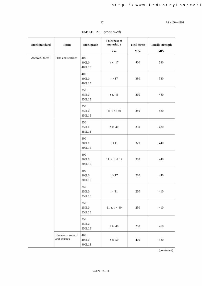
TABLE 2.1
STRENGTHS OF STEELS COMPLYING WITH AS 1163, AS/NZS 1594,AS/NZS 3678, AS/NZS 3679.1 AND AS/NZS 3679.2*
Steel Standard Form Steel gradeThickness ofmaterial, t Yield stress Tensile strength
mm MPa MPa
AS 1163 Hollow sections C450C450L0
All 450 500
C350C350L0
All 350 430
C250C250L0
All 250 320
AS/NZS 1594 Plate, strip and HA400 All 380 460
floorplateHW350 All 340 450
HA350 All 350 430
HA300/1 All 300 430
HA300HU300
All 300 400
HA250HU250
All 250 350
HA200 All 200 300
Plate and strip HA4N All 170 280
HA3 All 200 300
HA1 All (See Note 1) (See Note 1)
XF500 t � 8480
(See Note 2)570
XF400 t � 8 380 460
XF300 t � 8 300 440
AS/NZS 3678 Plate andfloorplate
450
450L15t � 20 450 520
450
450L1520 < t� 32 420 500
450
450L1532 < t � 50 400 500
400
400L15t � 12 400 480
(continued)
中国工业检验检测网 http://www.industryinspection.com

AS 4100—1998 26
COPYRIGHT
TABLE 2.1 (continued)
Steel Standard Tensile strengthYield stressThickness ofmaterial, tSteel gradeForm
mm MPa MPa
400
400L1512 < t � 20 380 480
400
400L1520 < t � 80 360 480
350
350L15t � 12 360 450
350
350L1512 < t � 20 350 450
350
350L1520 < t � 80 340 450
350
350L1580 < t � 150 330 450
WR350
WR350L0t � 50 340 450
300
300L15t � 8 320 430
300
300L158 < t � 12 310 430
300
300L1512 < t � 20 300 430
300
300L1520 < t � 150 280 430
250
250L15t � 8 280 410
250
250L158 < t � 12 260 410
250
250L1512 < t � 50 250 410
250L15 50 < t � 150 240 410
250 50 < t � 80 240 410
250 80 < t � 150 230 410
200 t � 12 200 300
(continued)
中国工业检验检测网 http://www.industryinspection.com
27 AS 4100—1998
COPYRIGHT
TABLE 2.1 (continued)
Steel Standard Tensile strengthYield stressThickness ofmaterial, tSteel gradeForm
mm MPa MPa
AS/NZS 3679.1 Flats and sections 400
400L0
400L15
t � 17 400 520
400
400L0
400L15
t > 17 380 520
350
350L0
350L15
t � 11 360 480
350
350L0
350L15
11 < t < 40 340 480
350
350L0
350L15
t � 40 330 480
300
300L0
300L15
t < 11 320 440
300
300L0
300L15
11 � t � 17 300 440
300
300L0
300L15
t > 17 280 440
250
250L0
250L15
t < 11 260 410
250
250L0
250L15
11 � t < 40 250 410
250
250L0
250L15t � 40 230 410
Hexagons, roundsand squares
400
400L0
400L15
t � 50 400 520
(continued)
中国工业检验检测网 http://www.industryinspection.com

AS 4100—1998 28
COPYRIGHT
TABLE 2.1 (continued)
Steel Standard Tensile strengthYield stressThickness ofmaterial, tSteel gradeForm
mm MPa MPa
400
400L0
400L15
50 < t < 100 380 520
400
400L0
400L15
t � 100 360 520
350
350L0
350L15
t � 50 340 480
350
350L0
350L15
50 < t < 100 330 480
350
350L0
350L15
t � 100 320 480
300
300L0
300L15
t � 50 300 440
300
300L0
300L15
50 < t < 100 290 440
300
300L0
300L15
t � 100 280 440
250
250L0
250L15
t � 50 250 410
250
250L0
250L15
t > 50 230 410
* Welded I-sections complying with AS/NZS 3679.2 are manufactured from hot-rolled structural steel platescomplying with AS/NZS 3678.
NOTES:
1 For design purposes, yield and tensile strengths approximate those of structural Grade HA200. For specificinformation, contact the supplier.
2 Clause 1.1(b) does not permit the yield stress (fy) used in design to exceed 450 MPa.
中国工业检验检测网 http://www.industryinspection.com

29 AS 4100—1998
COPYRIGHT
S E C T I O N 3 G E N E R A L D E S I G N R E Q U I R E M E N T S
3.1 DESIGN
3.1.1 Aim The aim of structural design is to provide a structure which is stable, has adequatestrength, is serviceable and durable, and which satisfies other objectives such as economy and ease ofconstruction.
A structure is stable if it does not overturn, tilt or slide throughout its intended life.
A structure has adequate strength and is serviceable if the probabilities of structural failure and of lossof serviceability throughout its intended life are acceptably low.
A structure is durable if it withstands the expected wear and deterioration throughout its intended lifewithout the need for undue maintenance.
3.1.2 Requirements The structure and its component members and connections shall satisfy thedesign requirements for stability, strength, serviceability, brittle fracture, fatigue, fire and earthquakein accordance with the procedures given in this Standard, as appropriate.
3.2 LOADS AND OTHER ACTIONS
3.2.1 Loads The design of a structure for the stability, strength and serviceability limit states shallaccount for the action effects directly arising from the following loads:
(a) Dead, live, wind, snow and earthquake loads specified in AS 1170.1, AS 1170.2, AS 1170.3and AS 1170.4.
(b) For the design of cranes, any relevant loads specified in AS 1418.
(c) For the design of fixed platforms, walkways, stairways and ladders, any relevant loadsspecified in AS 1657.
(d) For the design of lifts, any relevant loads specified in AS 1735.
(e) Other specific loads, as required.
NOTES:
1 For the design of bridges, loads specified in SAA HB77.2 or SAA HB77.8, as applicable, should beused.
2 For multi-storey building structures, see also Clause 3.2.4.
3.2.2 Other actions Any action which may significantly affect the stability, strength orserviceability of the structure, including the following, shall be taken into account:
(a) Foundation movements.
(b) Temperature changes and gradients.
(c) Axial shortening.
(d) Dynamic effects.
(e) Construction loading.
3.2.3 Design load combinations The design load combinations for the stability, strength andserviceability limit states shall be those specified in AS 1170.1.
NOTE: For the design of bridges, load combinations specified in SAA HB77.2 or SAA HB77.8, asapplicable, should be used.
3.2.4 Notional horizontal forces For multi-storey building structures only, notional horizontalforces, each equal to 0.002 times the total design vertical loads applied at a floor level, shall beapplied at that floor level. These notional horizontal forces shall be considered to act in conjunctionwith only the design dead and live loads from AS 1170.1 for the strength and serviceability limitstates. These notional horizontal forces shall not be included for the stability limit state.
中国工业检验检测网 http://www.industryinspection.com

AS 4100—1998 30
COPYRIGHT
3.3 STABILITY LIMIT STATE The structure as a whole (and any part of it) shall be designed toprevent instability due to overturning, uplift or sliding as follows:
(a) The loads determined in accordance with Clause 3.2 shall be subdivided into the componentstending to cause instability and the components tending to resist instability.
(b) The design action effect (S*) shall be calculated from the components of the loads tending tocause instability, combined in accordance with the load combinations for the strength limitstate specified in AS 1170.1.
(c) The design resistance effect shall be calculated as 0.8 times the part of the dead load tending toresist the instability plus the design capacity ( Ru) of any elements contributing towardsresisting the instability, where is a capacity factor which shall not exceed the appropriatevalue given in Table 3.4.
(d) The whole or part of the structure shall be proportioned so that the design resistance effect isnot less than the design action effect.
3.4 STRENGTH LIMIT STATE The structure and its component members and connectionsshall be designed for the strength limit state as follows:
(a) The loads and actions shall be determined in accordance with Clauses 3.2.1 and 3.2.2, and thestrength limit state design loads shall be determined in accordance with Clauses 3.2.3 and3.2.4.
(b) The design action effects (S*) resulting from the strength limit state design loads shall bedetermined by an analysis in accordance with Section 4.
(c) The design capacity ( Ru) shall be determined from the nominal capacity (Ru) determinedfrom Sections 5 to 9, as appropriate, where the capacity factor ( ) shall not exceed theappropriate value given in Table 3.4.
(d) All members and connections shall be proportioned so that the design capacity ( Ru) is not lessthan the design action effect (S*), i.e.—
S* � Ru
TABLE 3.4
CAPACITY FACTORS (�) FOR STRENGTH LIMIT STATES
Design capacity for Clauses Capacity factor ( )
Member subject to bending
—full lateral support
—segment without full lateral support
—web in shear
—web in bearing
—stiffener
5.1, 5.2 & 5.3
5.1 & 5.6
5.11 & 5.12
5.13
5.14, 5.15 & 5.16
0.90
0.90
0.90
0.90
0.90
Member subject to axial compression
—section capacity
—member capacity
6.1 & 6.2
6.1 & 6.3
0.90
0.90
Member subject to axial tension 7.1 & 7.2 0.90
Member subject to combined actions
—section capacity
—member capacity
8.3
8.4
0.90
0.90
(continued)
中国工业检验检测网 http://www.industryinspection.com

31 AS 4100—1998
COPYRIGHT
TABLE 3.4 (continued)
Design capacity for Capacity factor ( )Clauses
Connection component other than a bolt, pin or weld 9.1.9 0.90
Bolted connection
—bolt in shear
—bolt in tension
—bolt subject to combined shear and tension
—ply in bearing
—bolt group
9.3.2.1
9.3.2.2
9.3.2.3
9.3.2.4
9.4
0.80
0.80
0.80
0.90
0.80
Pin connection
—pin in shear
—pin in bearing
—pin in bending
—ply in bearing
9.5.1
9.5.2
9.5.3
9.5.4
0.80
0.80
0.80
0.90
Welded connection SP Category GP Category
—complete penetration butt weld
—longitudinal fillet weld in RHS (t < 3mm)
—other fillet weld and incomplete penetration butt weld
—plug or slot weld
—weld group
9.7.2.7
9.7.3.10
9.7.3.10
9.7.4
9.8
0.90
0.70
0.80
0.80
0.80
0.60
—
0.60
0.60
0.60
3.5 SERVICEABILITY LIMIT STATE
3.5.1 General The structure and its components shall be designed for the serviceability limit stateby controlling or limiting deflection, vibration, bolt slip and corrosion, as appropriate, in accordancewith the relevant requirements of Clauses 3.5.2 to 3.5.6.
3.5.2 Method The structure and its components shall be designed for the serviceability limit stateas follows:
(a) The loads and other actions shall be determined in accordance with Clauses 3.2.1 and 3.2.2,and the serviceability limit state design loads shall be determined in accordance withClauses 3.2.3 and 3.2.4.
(b) Deflections due to the serviceability limit state design loads shall be determined by thefirst-order elastic analysis method of Clause 4.4.2.1 with all amplification factors taken asunity. Deflections shall comply with Clause 3.5.3.
(c) Vibration behaviour shall be assessed in accordance with Clause 3.5.4.
(d) Bolt slip shall be limited, where required, in accordance with Clause 3.5.5.
(e) Corrosion protection shall be provided in accordance with Clause 3.5.6.
3.5.3 Deflection limits The deflection limits for the serviceability limit state shall be appropriateto the structure and its intended use, the nature of the loading, and the elements supported by it.
NOTE: Suggested deflection limits may be found in Appendix B.
3.5.4 Vibration of beams Beams which support floors or machinery shall be checked to ensurethat the vibrations induced by machinery, or vehicular or pedestrian traffic do not adversely affect theserviceability of the structure.
中国工业检验检测网 http://www.industryinspection.com

AS 4100—1998 32
COPYRIGHT
Where there is a likelihood of a structure being subjected to vibration from causes such as wind forcesor machinery, measures shall be taken to prevent discomfort or alarm, damage to the structure, orinterference with its proper function.
NOTE: AS 2670 gives guidance for the evaluation of human exposure to whole-body vibrations of the typelikely to be transmitted by structures.
3.5.5 Bolt serviceability limit state In a connection, where slip under the serviceability designloads shall be avoided, the fasteners shall be selected in accordance with Clause 9.1.6.
For a friction-type connection which is subject to shear force in the plane of the interfaces, and forwhich slip under serviceability loads shall be avoided, the capacity factor ( ) shall be taken as 0.7 andthe bolts shall be designed in accordance with Clause 9.3.3.
3.5.6 Corrosion protection Where steelwork in a structure is to be exposed to a corrosiveenvironment, the steelwork shall be given protection against corrosion. The degree of protection tobe employed shall be determined after consideration has been given to the use of the structure, itsmaintenance, and the climatic or other local conditions.
NOTE: Recommendations on corrosion protection may be found in Appendix C.
3.6 STRENGTH AND SERVICEABILITY LIMIT STATES BY LOAD TESTING Notwith-standing the requirements of Clause 3.4 or 3.5, a structure or a component member or connection maybe designed for the strength or serviceability limit state or both, by load-testing in accordance withSection 17. If this alternative procedure is adopted, the requirements of Clauses 3.7 to 3.11, asappropriate, shall also apply.
3.7 BRITTLE FRACTURE In order to avoid failure by brittle fracture, the selection of theparent material shall be made in accordance with Section 10.
3.8 FATIGUE For structures and structural elements subject to loadings which could lead tofatigue, the fatigue strength shall be determined in accordance with Section 11.
3.9 FIRE The structure, its component members and connections shall be designed in accordancewith Section 12.
3.10 EARTHQUAKE The structure, its component members, connections and anynon-structural components shall be designed for earthquake loads in accordance with AS 1170.4 andSection 13.
3.11 OTHER DESIGN REQUIREMENTS Requirements other than those listed inClause 3.1.2, such as differential settlement, progressive collapse and any special performancerequirements, shall be considered where relevant and, if significant, shall be taken into account in thedesign of the structure in accordance with the principles of this Standard and appropriate engineeringprinciples.
The design of bridges for loads resulting from floods or collision shall be carried out in accordancewith SAA HB77.2 or SAA HB77.8, as appropriate.
中国工业检验检测网 http://www.industryinspection.com

33 AS 4100—1998
COPYRIGHT
S E C T I O N 4 M E T H O D S O F S T R U C T U R A LA N A L Y S I S
4.1 METHODS OF DETERMINING ACTION EFFECTS
4.1.1 General For the purpose of complying with the requirements for the limit states of stability,strength and serviceability specified in Section 3, the design action effects in a structure and itsmembers and connections caused by the design loads shall be determined by structural analysis usingthe assumptions of Clauses 4.2 and 4.3 and one of the methods of—
(a) elastic analysis, in accordance with Clause 4.4;
(b) plastic analysis, in accordance with Clause 4.5; or
(c) advanced analysis, in accordance with Appendix D.
The design action effects for earthquake loads shall be obtained by an analysis complying withItem (a), (b) or (c). The earthquake loads calculated in accordance with AS 1170.4 shall be assumedto correspond to the load at which the first significant plastic hinge forms in the structure.
4.1.2 Definitions For the purpose of this Section, the definitions below apply:
(a) Braced member—one for which the transverse displacement of one end of the memberrelative to the other is effectively prevented. This applies to triangulated frames and trusses orto frames where in-plane stiffness is provided by diagonal bracing, or by shear walls, or byfloor slabs or roof decks secured horizontally to walls or to bracing systems parallel to theplane of buckling of the member.
(b) Sway member—one for which the transverse displacement of one end of the member relativeto the other is not effectively prevented. Such members occur in structures which depend onflexural action to limit the sway.
4.2 FORMS OF CONSTRUCTION ASSUMED FOR STRUCTURAL ANALYSIS
4.2.1 General The distribution of the design action effects throughout the members andconnections of a structure shall be determined by assuming one or a combination of the followingforms of construction:
(a) Rigid.
(b) Semi-rigid.
(c) Simple.
4.2.2 Rigid construction For rigid construction, the connections shall be assumed to havesufficient rigidity to hold the original angles between the members unchanged.
4.2.3 Semi-rigid construction For semi-rigid construction, the connections may not havesufficient rigidity to hold the original angles between the members unchanged, but shall be assumedto have the capacity to furnish a dependable and known degree of flexural restraint.
The relationship between the degree of flexural restraint and the level of the load effects shall beestablished by methods based on test results.
4.2.4 Simple construction For simple construction, the connections at the ends of members shallbe assumed not to develop bending moments.
4.2.5 Design of connections The design of all connections shall be consistent with the form ofconstruction, and the behaviour of the connections shall not adversely affect any other part of thestructure beyond what is allowed for in design. Connections shall be designed in accordance withSection 9.
中国工业检验检测网 http://www.industryinspection.com

AS 4100—1998 34
COPYRIGHT
4.3 ASSUMPTIONS FOR ANALYSIS
4.3.1 General The structure shall be analyzed in its entirety except as follows:
(a) Regular building structures may be analyzed as a series of parallel two-dimensionalsubstructures, the analysis being carried out in each of two directions at right angles, exceptwhen there is significant load redistribution between the substructures.
(b) For vertical loading in a multi-storey building structure provided with bracing or shear walls toresist all lateral forces, each level thereof together with the columns immediately above andbelow may be considered as substructures, the columns being assumed fixed at the endsremote from the level under consideration.
Where floor beams in a multi-storey building structure are considered as substructures, thebending moment at a support may be determined from the assumption that the floor is fixed atthe support one span away, provided that the floor beam continues beyond that point.
4.3.2 Span length The span length of a flexural member shall be taken as the distancecentre-to-centre of the supports.
4.3.3 Arrangements of live loads for buildings For building structures, the arrangements of liveloads considered in the analysis shall include at least the following:
(a) Where the loading pattern is fixed, the arrangement concerned.
(b) Where the nominal live load (Q) is variable and not greater than three-quarters of the nominaldead load (G), the design live load (Q*) on all spans.
(c) Where the nominal live load (Q) is variable and exceeds three-quarters of the nominal deadload (G), arrangements for the floor under consideration consisting of—
(i) the design live load (Q*) on alternate spans;
(ii) the design live load (Q*) on two adjacent spans; and
(iii) the design live load (Q*) on all spans.
4.3.4 Simple construction Bending members may be assumed to have their ends connected forshear only and to be free to rotate. In triangulated structures, axial forces may be determined byassuming that all members are pin connected.
A beam reaction or a similar load on a column shall be taken as acting at a minimum distance of100 mm from the face of the column towards the span or at the centre of bearing, whichever gives thegreater eccentricity, except that for a column cap, the load shall be taken as acting at the face of thecolumn, or edge of packing if used, towards the span.
For a continuous column, the design bending moment (M*) due to eccentricity of loading at any onefloor or horizontal frame level shall be taken as—
(a) ineffective at the floor or frame levels above and below that floor; and
(b) divided between the column lengths above and below that floor or frame level in proportion tothe values of I/l of the column lengths.
4.4 ELASTIC ANALYSIS
4.4.1 General
4.4.1.1 Assumptions Individual members shall be assumed to remain elastic under the action of thedesign loads for all limit states.
The effect of haunching or any variation of the cross-section along the axis of a member shall beconsidered and, where significant, shall be taken into account in the determination of the memberstiffness.

35 AS 4100—1998
COPYRIGHT
4.4.1.2 Second-order effects The analysis shall allow for the effects of the design loads acting onthe structure and its members in their displaced and deformed configuration. These second-ordereffects shall be taken into account by using either—
(a) a first-order elastic analysis with moment amplification in accordance with Clause 4.4.2,provided the moment amplification factors (�b) or (�s) are not greater than 1.4; or
(b) a second-order elastic analysis in accordance with Appendix E.
4.4.2 First-order elastic analysis
4.4.2.1 General In a first-order elastic analysis, changes in the geometry are not accounted for, andchanges in the effective stiffnesses of the members due to axial force are neglected. The effects ofthese on the first-order bending moments shall be allowed for by using one of the methods of momentamplification of Clause 4.4.2.2 or Clause 4.4.2.3 as appropriate, except that where the momentamplification factor (�b) or (�s), calculated in accordance with Clause 4.4.2.2 or Clause 4.4.2.3 asappropriate, is greater than 1.4, a second-order elastic analysis in accordance with Appendix E shallbe carried out.
The maximum calculated bending moment (M*m) shall be taken as the maximum bending moment
along the length of a member obtained by superposition of the simple beam bending momentsresulting from any transverse loading on the member with the end bending moments determined bythe analysis.
4.4.2.2 Moment amplification for a braced member For a braced member with zero axial force or abraced member subject to axial tension, the design bending moment (M*) shall be calculated asfollows:
M* M*m
For a braced member with a design axial compressive force (N*) as determined by the analysis, thedesign bending moment (M*) shall be calculated as follows:
M* �bM*m
where �b is a moment amplification factor for a braced member calculated as follows:
�b cm
1 � � N*
Nomb�� 1
and Nomb is the elastic buckling load, determined in accordance with Clause 4.6.2, for the bracedmember buckling about the same axis as that about which the design bending moment (M*) isapplied.
For a braced member subject to end bending moments only, the factor cm shall be calculated asfollows:
cm = 0.6 – 0.4ßm � 1.0
where ßm is the ratio of the smaller to the larger bending moment at the ends of the member, taken aspositive when the member is bent in reverse curvature.
The same expression for cm shall be used for a braced member with transverse load applied to it,provided that ßm is determined by one of the following methods:
(a) ßm = –1.0;
(b) ßm is approximated by the value obtained by matching the distribution of bending momentalong the member with one of the typical distributions of bending moment shown inFigure 4.4.2.2; or
(c) �m 1 ��2� ct
� cw� with –1.0 � ßm � 1.0
中国工业检验检测网 http://www.industryinspection.com

AS 4100—1998 36
COPYRIGHT
where
�ct = mid-span deflection of the member resulting from the transverse loading togetherwith both end bending moments, if any, as determined by the analysis
�cw = mid-span deflection of the member resulting from the transverse loading togetherwith only those end bending moments which produce a mid-span deflection in thesame direction as the transverse load.
4.4.2.3 Moment amplification for a sway member For a sway member, the design bending moment(M*) shall be calculated using either the method given in this Clause, or the method given inAppendix F.
For this Clause, the design bending moment (M*) shall be calculated as follows:
M* = �mM*m
The moment amplification factor (�m) shall be taken as the greater of—
�b = the moment amplification factor for a braced member determined in accordance withClause 4.4.2.2, and
�s = the moment amplification factor for a sway member determined as follows:
(a) Sway members in rectangular frames For all sway columns in a storey of arectangular frame, the amplification factor (�s) shall be calculated from—
(i) �s 1
1 ���shs
ΣN*
ΣV*�
where �s is the translational displacement of the top relative to the bottom inthe storey of height (hs), caused by the design horizontal storey shears (V*) atthe column ends, N* is the design axial force in a column of the storey, and thesummations include all the columns of the storey;
(ii) �s 1
1 � � 1ms�
where the elastic buckling load factor (ms) for the storey underconsideration is determined in accordance with Clause 4.7.2.2.; or
(iii) �s 1
1 � � 1c�
where the elastic buckling load factor (c) is determined from a rationalbuckling analysis of the whole frame (see Clause 4.7.2).
(b) Sway members in non-rectangular frames The amplification factor (�s) for eachsway member shall be taken as the value for the frame calculated as follows:
�s 1
1 � � 1c�
where the elastic buckling load factor (c) is determined from a rationalbuckling analysis of the whole frame (see Clause 4.7.2).
中国工业检验检测网 http://www.industryinspection.com

37 AS 4100—1998
COPYRIGHT
FIGURE 4.4.2.2 (in part) VALUES OF ßm FOR VARIOUS DISTRIBUTIONSOF BENDING MOMENT
中国工业检验检测网 http://www.industryinspection.com

AS 4100—1998 38
COPYRIGHT
FIGURE 4.4.2.2 (in part) VALUES OF ßm FOR VARIOUS DISTRIBUTIONSOF BENDING MOMENT

39 AS 4100—1998
COPYRIGHT
4.5 PLASTIC ANALYSIS
4.5.1 Application The design action effects throughout all or part of a structure may bedetermined by a plastic analysis provided that the limitations of Clause 4.5.2 are observed. Thedistribution of design action effects shall satisfy equilibrium and the boundary conditions.
4.5.2 Limitations When a plastic method of analysis is used, all of the following conditions shallbe satisfied unless adequate ductility of the structure and plastic rotation capacity of its members andconnections are established for the design loading conditions:
(a) The minimum yield stress specified for the grade of the steel shall not exceed 450 MPa.
(b) The stress-strain characteristics of the steel shall not be significantly different from thoseobtained for steels complying with AS/NZS 3678 or AS/NZS 3679.1, and shall be such as toensure moment redistribution.
This requirement may be deemed to be satisfied if—
(i) the stress-strain diagram has a plateau at the yield stress extending for at least six timesthe yield strain;
(ii) the ratio of the tensile strength to the yield stress specified for the grade of the steel (seeTable 2.1) is not less than 1.2;
(iii) the elongation on a gauge length complying with AS 1391 is not less than 15%; and
(iv) the steel exhibits a strain-hardening capability.
(c) The members used shall be hot-formed.
(d) The members used shall be doubly symmetric I-sections.
(e) The geometry of the member sections shall comply with the requirements specified for acompact section in Clause 5.2.3.
(f) The members shall not be subject to impact loading or fluctuating loading requiring a fatigueassessment (see Section 11).
4.5.3 Assumptions of analysis The design action effects shall be determined using a rigid plasticanalysis.
It shall be permissible to assume full strength or partial strength connections, provided the capacitiesof these are used in the analysis, and provided that—
(a) for a full strength connection, for which the moment capacity of the connection shall be notless than that of the member being connected, the behaviour of the connection shall be suchthat the rotation capacity at none of the hinges in the collapse mechanism is exceeded; and
(b) for a partial strength connection, for which the moment capacity of the connection may be lessthan that of the member being connected, the behaviour of the connection shall be such as toallow all plastic hinges necessary for the collapse mechanism to develop, and shall be such thatthe rotation capacity at none of the plastic hinges is exceeded.
4.5.4 Second order effects Any second-order effects of the loads acting on the structure in itsdeformed configuration may be neglected where the elastic buckling load factor (c) (see Clause 4.7)satisfies—
10 � c
For 5 � c < 10, second-order effects may be neglected provided the design load effects are amplifiedby a factor �p
where
�p 0.9
1 � � 1c�
For c < 5, a second-order plastic analysis shall be carried out.

AS 4100—1998 40
COPYRIGHT
4.6 MEMBER BUCKLING ANALYSIS
4.6.1 General The elastic buckling load of a member (Nom) for the particular conditions of endrestraint provided by the surrounding frame shall be determined in accordance with Clause 4.6.2.The member buckling load (Nomb) is used in the determination of the moment amplification factor fora braced member (�b) in Clause 4.4.2.2, and the member buckling load (Noms) in the determination ofthe elastic buckling load factor (ms) in Clause 4.7.2.2 which is used in the determination of themoment amplification factor for a sway member (�s) in Clause 4.4.2.3.
4.6.2 Member elastic buckling load The elastic buckling load of a member (Nom) shall bedetermined as follows:
Nom �2EI(kel)2
where ke is the member effective length factor, determined in accordance with Clause 4.6.3 and l isthe member length from centre to centre of its intersections with supporting members.
4.6.3 Member effective length factor4.6.3.1 General The value of the member effective length factor (ke) depends on the rotationalrestraints and the translational restraints at the ends of the member. In Figure 4.6.3.3(a) for a bracedmember, the translational restraint has been assumed to be infinite. In Figure 4.6.3.3(b) for a swaymember, the translational restraint has been assumed to be zero.
The value of the member effective length factor (ke) shall be determined in accordance with thefollowing:(a) Clause 4.6.3.2 for members with idealized end restraints.(b) Clause 4.6.3.3 or Appendix G for braced members in frames.(c) Clause 4.6.3.3 for sway members in rectangular frames with regular loading and negligible
axial forces in the beams.(d) Clause 4.6.3.5 for members in triangulated structures.
4.6.3.2 Members with idealized end restraints Values of the member effective length factor (ke)which shall be used for some idealized conditions of end restraint for members are given inFigure 4.6.3.2.
Braced member Sway member
Buckledshape
Effective lengthfactor (ke)
0.7 0.85 1.0 1.2 2.2 2.2
Symbols for= Rotation fixed, translation fixed = Rotation fixed, translation fixed
end restraintconditions
= Rotation free, translation fixed = Rotation free, translation fixed
FIGURE 4.6.3.2 EFFECTIVE LENGTH FACTORS FOR MEMBERS FORIDEALIZED CONDITIONS OF END RESTRAINT
中国工业检验检测网 http://www.industryinspection.com
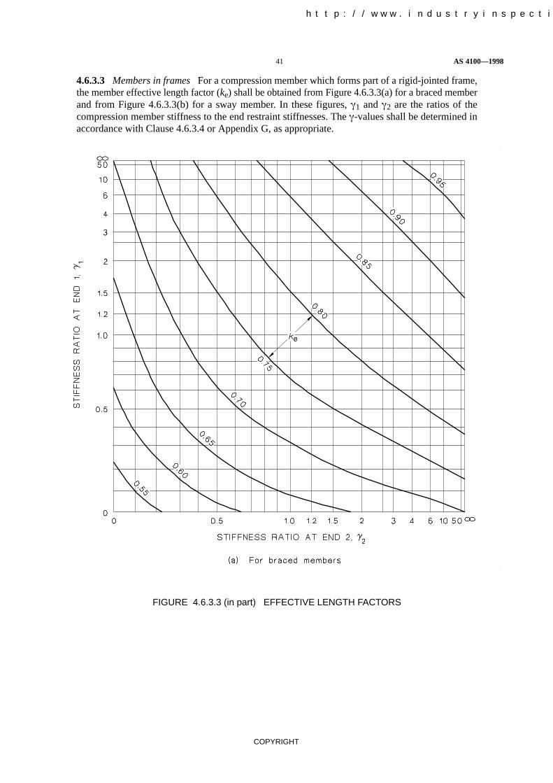
41 AS 4100—1998
COPYRIGHT
4.6.3.3 Members in frames For a compression member which forms part of a rigid-jointed frame,the member effective length factor (ke) shall be obtained from Figure 4.6.3.3(a) for a braced memberand from Figure 4.6.3.3(b) for a sway member. In these figures, �1 and �2 are the ratios of thecompression member stiffness to the end restraint stiffnesses. The �-values shall be determined inaccordance with Clause 4.6.3.4 or Appendix G, as appropriate.
FIGURE 4.6.3.3 (in part) EFFECTIVE LENGTH FACTORS
中国工业检验检测网 http://www.industryinspection.com

AS 4100—1998 42
COPYRIGHT
FIGURE 4.6.3.3 (in part) EFFECTIVE LENGTH FACTORS
4.6.3.4 Stiffness ratios in rectangular frames The �-value of a compression member in arectangular frame with regular loading and negligible axial forces in the beams shall be calculated asfollows:
� Σ�Il�c
Σ�e�Il�bexcept that—
(a) for a compression member whose base is not rigidly connected to a footing, the �-value shallnot be taken as less than 10 unless a rational analysis would justify a different value; and
(b) for a compression member whose end is rigidly connected to a footing, the �-value shall not betaken as less than 0.6, unless a rational analysis would justify a different value.

43 AS 4100—1998
COPYRIGHT
The quantity Σ(I/l)c shall be calculated from the sum of the stiffnesses in the plane of bending of allthe compression members rigidly connected at the end of the member under consideration, includingthe member itself.
The quantity Σße(I/l)b shall be calculated from the sum of the stiffnesses in the plane of bending for allthe beams rigidly connected at the end of the member under consideration. The contributions of anybeams pin-connected to the member shall be neglected.
The modifying factor (ße) which accounts for the conditions at the far ends of the beams, shall be asgiven in Table 4.6.3.4.
TABLE 4.6.3.4
MODIFYING FACTORS (ße)
Fixity conditionsat far end of beam
Beam restraining a bracedmember
Beam restraininga sway member
Pinned 1.5 0.5
Rigidly connected to a column 1.0 1.0
Fixed 2.0 0.67
4.6.3.5 Members in triangulated structures The effective length (le) of a member in a triangulatedstructure shall be taken as not less than its length (l) from centre to centre of intersections with othermembers, unless shown otherwise by a rational elastic buckling analysis consistent withAppendix G.
4.7 FRAME BUCKLING ANALYSIS
4.7.1 General The elastic buckling load factor (c) shall be the ratio of the elastic buckling load setof the frame to the design load set for the frame, and shall be determined in accordance withClause 4.7.2. The elastic buckling load factor (c) is used in the determination of the momentamplification factor for a sway member (�s) in Clause 4.4.2.3(b) and in establishing limits for themethods of analysis in Clause 4.5.4 and Appendix E.
NOTE: The value of c depends on the load set.
4.7.2 In-plane frame buckling The elastic buckling load factor (c) of a rigid-jointed frame shallbe determined by using—
(a) one of the approximate methods of Clauses 4.7.2.1 and 4.7.2.2; or
(b) a rational elastic buckling analysis of the whole frame.
NOTE: The value of c depends on the load set.
4.7.2.1 Rectangular frames with all members braced In a rectangular frame with regular loadingand negligible axial forces in the beams, the braced member buckling load (Nomb) for each columnshall be determined in accordance with Clauses 4.6.2, 4.6.3.3 and 4.6.3.4.
The elastic buckling load factor (m) for each column shall be determined as follows:
m Nomb
N*
The elastic buckling load factor (c) for the whole frame shall be taken as the lowest of all the mvalues.
中国工业检验检测网 http://www.industryinspection.com

AS 4100—1998 44
COPYRIGHT
4.7.2.2 Rectangular frames with sway members In a rectangular frame with regular loading andnegligible axial forces in the beams, the member buckling load (Noms) for each column shall bedetermined in accordance with Clauses 4.6.2, 4.6.3.3 and 4.6.3.4.
The elastic buckling load factor (ms) for each storey shall be determined as follows:
ms Σ�Noms
l�
Σ�N*
l�
where
N* = member design axial force, with tension taken as negative, and the summation includes allcolumns within a storey.
The elastic buckling load factor (c) for the whole frame shall be taken as the lowest of all the msvalues.
中国工业检验检测网 http://www.industryinspection.com

45 AS 4100—1998
COPYRIGHT
S E C T I O N 5 M E M B E R S S U B J E C T T O B E N D I N G
5.1 DESIGN FOR BENDING MOMENT A member bent about the section major principalx-axis which is analyzed by the elastic method (see Clause 4.4) shall satisfy—
M*x � Msx, and
M*x � Mbx
where
M*x = the design bending moment about the x-axis determined in accordance with Clause 4.4.
= the capacity factor (see Table 3.4)
Msx = the nominal section moment capacity, as specified in Clause 5.2, for bending about thex-axis
Mbx = the nominal member moment capacity, as specified in Clause 5.3 or 5.6, for bendingabout the x-axis.
A member bent about the section minor principal y-axis which is analyzed by the elastic method (seeClause 4.4) shall satisfy—
M*y � Msy
where
M*y = the design bending moment about the y-axis determined in accordance with Clause 4.4.
Msy = the nominal section moment capacity, as specified in Clause 5.2, for bending about they-axis.
A member which is analyzed by the plastic method (see Clause 4.5) shall be compact at all sectionswhere plastic hinges may form (see Clause 5.2.3), shall have full lateral restraint as specified inClause 5.3.2, and its web shall satisfy Clause 5.10.6. The member shall satisfy—
M* � Ms
where
M* = the design bending moment determined in accordance with Clause 4.5, and
Ms = the nominal section moment capacity as specified in Clause 5.2.1.
A member whose deflections are constrained to a non-principal plane shall be analyzed as specifiedin Clause 5.7.1, and shall satisfy Clause 8.3.4.
A member which is bent about a non-principal axis and whose deflections are unconstrained shall beanalyzed as specified in Clause 5.7.2, and shall satisfy Clauses 8.3.4 and 8.4.5.
A member subjected to combined bending and shear shall satisfy the requirements of this Clause andClause 5.12.
A member subjected to combined bending and axial compression or tension shall satisfy Section 8.
5.2 SECTION MOMENT CAPACITY FOR BENDING ABOUT A PRINCIPAL AXIS
5.2.1 General The nominal section moment capacity (Ms) shall be calculated as follows:
Ms = fyZe
where the effective section modulus (Ze) shall be as specified in Clauses 5.2.3, 5.2.4, or 5.2.5 asappropriate.
中国工业检验检测网 http://www.industryinspection.com

AS 4100—1998 46
COPYRIGHT
5.2.2 Section slenderness For a section with flat compression plate elements, the sectionslenderness (s) shall be taken as the value of the plate element slenderness (e) for the element of thecross-section which has the greatest value of e/ey—
where
e �bt� � fy
250��
ey = the plate element yield slenderness limit (see Table 5.2)
b = the clear width of the element outstand from the face of the supporting plate element orthe clear width of the element between the faces of supporting plate elements
t = the element thickness.
The section plasticity and yield slenderness limits (sp) and (sy) respectively shall be taken as thevalues of the element slenderness limits (ep) and (ey) respectively given in Table 5.2 for theelement of the cross-section which has the greatest value of e/ey.
For circular hollow sections, the section slenderness (s) shall be calculated as follows:
s �dot � � fy
250�
where do is the outside diameter of the section. The section plasticity and yield slenderness limits(sp) and (sy) respectively shall be taken as the values of the element slenderness limits (ep) and(ey) respectively given in Table 5.2.
TABLE 5.2
VALUES OF PLATE ELEMENT SLENDERNESS LIMITS
Plateelement
type
Longitudinaledges
supported
Residualstresses
(see Notes)
Plasticitylimit(ep)
Yieldlimit(ey)
Deformationlimit(ed)
Flat OneSR
HR
10
9
16
16
35
35
(Uniform compression)
HR
LW, CF
HW
9
8
8
16
15
14
35
35
35
Flat One SR 10 25 —
Maximum compression at unsupportededge, zero stress or tension at supportededge)
HR
LW, CF
HW
9
8
8
25
22
22
—
—
—
Flat Both SR
HR
30
30
45
45
90
90
(Uniform compression)
HR
LW, CF
HW
30
30
30
45
40
35
90
90
90
Flat Both
(Compression at one edge, tension at theother)
Any 82 115 —
(continued)
中国工业检验检测网 http://www.industryinspection.com

47 AS 4100—1998
COPYRIGHT
TABLE 5.2 (continued)
Plateelement
type
Deformationlimit(ed)
Yieldlimit(ey)
Plasticitylimit(ep)
Residualstresses
(see Notes)
Longitudinaledges
supported
Circular hollow sections
SR
HR, CF
LW
HW
50
50
42
42
120
120
120
120
—
—
—
—
NOTES:
1 SR—stress relievedHR—hot-rolled or hot-finishedCF—cold formed LW—lightly welded longitudinallyHW—heavily welded longitudinally
2 Welded members whose compressive residual stresses are less than 40 MPa may be considered to be lightly welded.
5.2.3 Compact sections For sections which satisfy s � sp, the effective section modulus (Ze)shall be the lesser of S or 1.5Z, where S and Z are the plastic and elastic section moduli respectively,determined in accordance with Clause 5.2.6.
5.2.4 Non-compact sections For sections which satisfy sp < s � sy, the effective sectionmodulus (Ze) shall be calculated as follows:
Ze Z �� sy � s
sy � sp�(Zc � Z)�
where Zc is the effective section modulus (Ze) for a compact section specified in Clause 5.2.3.
5.2.5 Slender sections For sections with flat plate elements in uniform compression which satisfys > sy, the effective section modulus (Ze) shall be calculated either as follows:
Ze Z�sy
s�
or for the effective cross-section determined by omitting from each flat compression element thewidth in excess of the width corresponding to �sy.
For a section whose slenderness is determined by the value calculated for a flat plate element withmaximum compression at an unsupported edge and zero stress or tension at the other edge and whichsatisfies s > sy, the effective section modulus (Ze) shall be calculated as follows:
Ze Z�sy
s�
2
For circular hollow sections which satisfy s > sy, the effective section modulus shall be taken as thelesser of—
Ze Z �sy
s�� and
Ze Z�2sy
s�
2
中国工业检验检测网 http://www.industryinspection.com

AS 4100—1998 48
COPYRIGHT
For elements where e > ed in which ed is the deformation slenderness limit given in Table 5.2,noticeable deformations may occur under service loading.
5.2.6 Elastic and plastic section moduli For sections without holes, or for sections with holesthat reduce either of the flange areas by not more than 100{1 – [fy/(0.85fu)]}%, the elastic and plasticsection moduli may be calculated using the gross section.
For sections with holes that reduce either of the flange areas by more than 100{1 – [fy/(0.85fu)]}%,the elastic and plastic section moduli shall be calculated using either—
(a) (An/Ag) times the value for the gross section, in which An is the sum of the net areas of theflanges and the gross area of the web, and Ag the gross area of the section; or
(b) the net section.
When net areas are calculated, any deductions for fastener holes shall be made in accordance withClause 9.1.10.
5.3 MEMBER CAPACITY OF SEGMENTS WITH FULL LATERAL RESTRAINT
5.3.1 Member capacity The nominal member moment capacity (Mb) of a segment with fulllateral restraint shall be taken as the nominal section moment capacity (Ms) (see Clause 5.2) of thecritical section (see Clause 5.3.3).
A segment in a member subjected to bending is the length between adjacent cross-sections which arefully or partially restrained (see Clauses 5.4.2.1 and 5.4.2.2), or the length between an unrestrainedend (see Clause 5.4.1) and the adjacent cross-section which is fully or partially restrained.
5.3.2 Segments with full lateral restraint
5.3.2.1 General A segment may be considered to have full lateral restraint if it satisfies one of thefollowing clauses: Clause 5.3.2.2, 5.3.2.3 or Clause 5.3.2.4, or if its nominal member momentcapacity (Mb) calculated in accordance with Clause 5.6 is not less than the nominal section momentcapacity (Ms) (see Clause 5.2) at the critical section (see Clause 5.3.3).
5.3.2.2 Segments with continuous lateral restraints A segment with continuous lateral restraintsmay be considered to have full lateral restraint, provided that—
(a) both ends are fully or partially restrained (see Clauses 5.4.2.1, 5.4.2.2, 5.4.3.1, and 5.4.3.2);and
(b) the continuous restraints act at the critical flange (see Clause 5.5), and satisfy Clause 5.4.3.1.
5.3.2.3 Segments with intermediate lateral restraints A segment with intermediate lateralrestraints (see Clauses 5.4.2.4 and 5.4.3.1) which divide the segment into a series of sub-segmentsmay be considered to have full lateral restraint, provided that—
(a) both ends are fully or partially restrained (see Clauses 5.4.2.1, 5.4.2.2, 5.4.3.1 and 5.4.3.2);
(b) the length (l) of each sub-segment satisfies Clause 5.3.2.4; and
(c) the lateral restraints act at the critical flange (see Clause 5.5), and satisfy Clause 5.4.3.1.
5.3.2.4 Segments with full or partial restraints at both ends A segment with full or partial restraintsat both ends (see Clauses 5.4.2.1, 5.4.2.2, 5.4.3.1 and 5.4.3.2) may be considered to have full lateralrestraint, provided its length (l) satisfies—
lry
� (80 50�m) �250fy�� if the segment is of equal flanged I-section;
lry
� (60 40�m) �250fy�� if the segment is an equal flanged channel;
中国工业检验检测网 http://www.industryinspection.com

49 AS 4100—1998
COPYRIGHT
lry
� (80 50�m) ���2�Adf
2.5Zex�� ���250
fy�� if the segment is of I-section with unequal
flanges;
lry
� (1800 1500�m)�bf
bw��250
fy� if the segment is of rectangular or square hollow
section; or
lt � (210 175�m)
��
�b2
b1�� ���250
fy� if the segment is of angle section.
where
A = area of cross-section
bf, bw = the flange width and web depth, respectively
b1, b2 = the greater and lesser leg lengths, respectively
df = the distance between flange centroids
Icy = the second moment of area of the compression flange about the section minor y-axis
Iy = the second moment of area of the section about the section minor principal y-axis
ry = the radius of gyration about the minor principal y-axis
t = the thickness of an angle section
Ze = the effective section modulus (see Clause 5.2)
� = Icy/Iy
The ratio ßm shall be taken as one of the following as appropriate:
(a) –1.0;
(b) –0.8 for segments with transverse loads; or
(c) the ratio of the smaller to the larger end moments in the length (l), (positive when the segmentis bent in reverse curvature and negative when bent in single curvature) for segments withouttransverse loads.
5.3.3 Critical section The critical section in a segment shall be taken as the cross-section whichhas the largest value of the ratio of the design bending moment (M*) to the nominal section capacity inbending (Ms) (see Clause 5.2).
5.4 RESTRAINTS
5.4.1 General A cross-section may be considered to be fully, partially, rotationally or laterallyrestrained if its restraints satisfy the appropriate requirements of Clause 5.4.2.
Restraints against lateral deflection, twist rotation, or lateral rotation may be considered to beeffective if they satisfy the appropriate requirements of Clause 5.4.3.
The members and connections of restraint systems shall be designed to transfer the appropriate forcesand bending moments specified in Clause 5.4.3, together with any other forces or bending momentswhich may act simultaneously, from the points where the forces or bending moments arise toanchorage or reaction points.
Any cross-section of a member which does not satisfy any of Clauses 5.4.2.1 to 5.4.2.4 shall beconsidered to be unrestrained, as for example in Figure 5.4.1, unless the member capacity in bendingis determined by the method of design by buckling analysis (see Clause 5.6.4).
中国工业检验检测网 http://www.industryinspection.com

AS 4100—1998 50
COPYRIGHT
FIGURE 5.4.1 UNRESTRAINED CROSS-SECTIONS
5.4.2 Restraints at a cross-section5.4.2.1 Fully restrained A cross-section of a member may be considered to be fully restrained ifeither—(a) the restraint or support effectively prevents lateral deflection of the critical flange (see
Clause 5.5), and effectively prevents twist rotation of the section, as for example inFigure 5.4.2.1(a); or partially prevents twist rotation of the section, as for example inFigure 5.4.2.1(b).
(b) the restraint or support effectively prevents lateral deflection of some other point in thecross-section, and effectively prevents twist rotation of the section, as for example inFigure 5.4.2.1(c).
FIGURE 5.4.2.1 FULLY RESTRAINED CROSS-SECTIONS
中国工业检验检测网 http://www.industryinspection.com

51 AS 4100—1998
COPYRIGHT
5.4.2.2 Partially restrained A cross-section of a member may be considered to be partiallyrestrained if the restraint or support effectively prevents lateral deflection of some point in thecross-section other than the critical flange, and partially prevents twist rotation of the section, as forexample in Figure 5.4.2.2.
FIGURE 5.4.2.2 PARTIALLY RESTRAINED CROSS-SECTIONS
5.4.2.3 Rotationally restrained A cross-section of a member which may be considered to be fullyor partially restrained may be considered to be rotationally restrained when the restraint or supportprovides significant restraint against lateral rotation of the critical flange (see Clause 5.5) out of theplane of bending, as for example in Figure 5.4.2.3.
FIGURE 5.4.2.3 ROTATIONALLY RESTRAINED CROSS-SECTIONS
5.4.2.4 Laterally restrained A cross-section of a segment whose ends are fully or partiallyrestrained may be considered to be laterally restrained when the restraint effectively prevents lateraldeflection of the critical flange (see Clause 5.5) but is ineffective in preventing twist rotation of thesection, as for example in Figure 5.4.2.4. Cross-sections in member segments with one endunrestrained shall not be considered to be laterally restrained.
中国工业检验检测网 http://www.industryinspection.com

AS 4100—1998 52
COPYRIGHT
FIGURE 5.4.2.4 LATERALLY RESTRAINED CROSS-SECTION
5.4.3 Restraining elements
5.4.3.1 Restraint against lateral deflection The lateral restraint at any cross-section considered tobe fully, partially or laterally restrained in terms of Clause 5.4.2 shall be designed to transfer atransverse force acting at the critical flange (see Clause 5.5) equal to 0.025 times the maximum forcein the critical flanges of the adjacent segments or sub-segments, except where the restraints are moreclosely spaced than is required to ensure that M* equals Mb.When the restraints are more closely spaced, then a lesser force may be designed for. The actualarrangement of restraints shall be assumed to be equivalent to a set of restraints which will ensure thatM* equals Mb. Each equivalent restraint shall correspond to an appropriate group of the actualrestraints. This group shall then be designed as a whole to transfer the transverse force of 0.025 timesthe maximum force in the critical flanges of the equivalent adjacent segments or sub-segments.
5.4.3.2 Restraint against twist rotation A torsional restraint at a cross-section may be deemed toprovide effective restraint against twist rotation if it is designed to transfer a transverse force equal to0.025 times the maximum force in the critical flange from any unrestrained flange to the lateralrestraint.A torsional restraint at a cross-section may be deemed to provide partial restraint against twistrotation if it is able to provide an elastic restraint against twist rotation without rotational slip.Flexible elements such as unstiffened webs may form part of such a restraint provided that they areconnected in such a way as to prevent rotational slip.Any restraint at a cross-section which permits rotational slip shall be deemed to be ineffective inrestraining twist rotation.
NOTE: Guidance on the effects of the stiffness of a torsional restraint on the resistance to lateral buckling isgiven in Paragraph H5.1 of Appendix H.
5.4.3.3 Parallel restrained members When a series of parallel members is restrained by a line ofrestraints, each restraining element shall be designed to transfer a transverse force equal to the sum of0.025 times the flange force from the connected member and 0.0125 times the sum of the flangeforces in the connected members beyond, except that no more than seven members need beconsidered.
5.4.3.4 Restraint against lateral rotation A rotational restraint at a cross-section which isconsidered to be fully or partially restrained (see Clauses 5.4.2.1, 5.4.2.2 and 5.4.2.3) may be deemedto provide restraint against lateral rotation out of the plane of bending, providing its flexural stiffnessin the plane of rotation is comparable with the corresponding stiffness of the restrained member.
NOTE: Guidance on the effects of the stiffness of a rotational restraint on the resistance to lateral buckling isgiven in Paragraph H5.2 of Appendix H.
A segment which has full lateral restraint (see Clause 5.3.2) may be deemed to provide rotationalrestraint to an adjacent segment which is laterally continuous with it.A segment which does not have full lateral restraint shall be assumed to be unable to providerotational restraint to an adjacent segment, unless the member resistance is determined by the methodof design by buckling analysis in accordance with Clause 5.6.4.
中国工业检验检测网 http://www.industryinspection.com

53 AS 4100—1998
COPYRIGHT
5.5 CRITICAL FLANGE
5.5.1 General The critical flange at any cross-section is the flange which in the absence of anyrestraint at that section would deflect the farther during buckling.
The critical flange may be determined by an elastic buckling analysis (see Clause 5.6.4) or asspecified in Clauses 5.5.2 and 5.5.3.
5.5.2 Segments with both ends restrained The critical flange at any section of a segmentrestrained at both ends shall be the compression flange.
5.5.3 Segments with one end unrestrained When gravity loads are dominant, the critical flangeof a segment with one end unrestrained shall be the top flange.
When wind loads are dominant, the critical flange shall be the exterior flange in the case of externalpressure or internal suction, and shall be the interior flange in the case of internal pressure or externalsuction.
5.6 MEMBER CAPACITY OF SEGMENTS WITHOUT FULL LATERAL RESTRAINT
5.6.1 Segments fully or partially restrained at both ends
5.6.1.1 Open sections with equal flanges For open sections with equal flanges, the following shallbe considered:
(a) Segments of constant cross-section The nominal member moment capacity (Mb) shall becalculated as follows:
Mb = �m�sMs � Ms . . . 5.6.1.1(1)
where
�m = a moment modification factor
�s = a slenderness reduction factor
Ms = the nominal section moment capacity determined in accordance with Clause 5.2for the gross section.
The moment modification factor (�m) shall be taken as one of the following:
(i) 1.0;
(ii) a value obtained from Table 5.6.1;
(iii) �� ���
�
��������� ����
��� ����
������
� ��
where
M*m = maximum design bending moment in the segment
M*2 , M*
4 = design bending moments at the quarter points of the segment
M*3 = design bending moment at the midpoint of the segment; or
(iv) a value obtained from an elastic buckling analysis in accordance with Clause 5.6.4,
except that for sub-segments formed by intermediate lateral restraints in segments fully orpartially restrained at both ends, the sub-segment moment distribution shall be used instead ofthe segment moment distribution when using (ii) or (iii).
The slenderness reduction factor (�s) shall be determined as follows:
�s 0.6 ����Ms
Moa�
2
3�� ��MsMoa� ��
. . . 5.6.1.1(2)
中国工业检验检测网 http://www.industryinspection.com

AS 4100—1998 54
COPYRIGHT
in which Moa shall be taken as either—
(A) Moa = Mo, where Mo is the reference buckling moment; or(B) the value determined from an elastic buckling analysis in accordance with
Clause 5.6.4.
The reference buckling moment (Mo) shall be determined as follows:
Mo ����2EIy
l2e��GJ ��2EIw
l2e�� ��� . . . 5.6.1.1(3)
where
E, G = the elastic moduli (see Clause 1.4)Iy, J, and Iw = section constants (see Clause 1.4)le = the effective length determined in accordance with Clause 5.6.3.
NOTE: Values of E and G and expressions for J and Iw are given in Paragraph H4 of Appendix H.
(b) Segments of varying cross-section The nominal member moment capacity (Mb) shall bedetermined in accordance with Clause 5.6.1.1(a) and using either—
(i) the properties of the minimum cross-section;
(ii) the properties of the critical cross-section as specified in Clause 5.3.3, provided thatthe value of Moa determined in accordance with Clause 5.6.1.1(a) is reduced, before itis used in Equation 5.6.1.1(2), by multiplying it by the reduction factor (�st) asfollows:
�st = 1.0 – [1.2rr(1 – rs)]
where
rr = lr/l for stepped members
= 0.5 for tapered members
rs =Afm
Afc�0.6 �0.4dm
dc��
Afm, Afc = the flange areas at the minimum and critical cross-sections,respectively
dm, dc = the section depths at the minimum and critical cross-sections,respectively
lr = the length of the segment over which the cross-section is reduced
l = the length of the segment; or
(iii) the method of design by buckling analysis (see Clause 5.6.4).
5.6.1.2 I-sections with unequal flanges The nominal member moment capacity (Mb) shall bedetermined in accordance with Clause 5.6.1.1(a), except that the reference buckling moment (Mo)shall be determined by using either—
(a) Mo ��2EIy
l2e�� �
��(GJ) ��2EIw
l2e���2
x4�
2EIy
l2e���
�x
2��2EIy
l2e�� �
� ; or
(b) the method of design by buckling analysis (see Clause 5.6.4).

55 AS 4100—1998
COPYRIGHT
The monosymmetry section constant (ßx) shall be determined using either—
(i) �x 0.8df��2Icy
Iy�� 1�
where
df = the distance between flange centroids
Icy = the second moment of area of the compression flange about the section minorprincipal y-axis; or
(ii) �x 1Ix��x2y y3 �dA � 2yo
where yo is the coordinate of the shear centre (see Reference H6.11 of Appendix H). The valuesof ßx are positive when the larger flange is in compression, and negative when the smallerflange is in compression.
5.6.1.3 Angle sections The nominal member moment capacity (Mb) of an angle section shall bedetermined in accordance with Clause 5.6.1.1(a) using Iw equals 0.
5.6.1.4 Hollow sections The nominal member moment capacity (Mb) of a rectangular hollowsection shall be determined in accordance with Clause 5.6.1.1(a) using Iw equals 0.
5.6.2 Segments unrestrained at one end The nominal member moment capacity (Mb) of asegment unrestrained at one end and at the other end both—
(a) fully or partially restrained; and
(b) laterally continuous or restrained against lateral rotation
shall be determined using either—
(i) Equations 5.6.1.1(1) and 5.6.1.1(2) with Moa equal to the value of Mo obtained fromEquation 5.6.1.1(3), and the appropriate value of �m given in Table 5.6.2; or
(ii) Mb = �sMs � Ms
where the slenderness reduction factor (�s) shall be determined as follows:
�s 0.6 �
� ���Ms
Mob�
2
3 ��� ��Ms
Mob� �
�where Ms is the nominal section moment capacity determined in accordance withClause 5.2 for the gross section, and Mob is determined by an elastic buckling analysisin accordance with Clause 5.6.4.
中国工业检验检测网 http://www.industryinspection.com

AS 4100—1998 56
COPYRIGHT
TABLE 5.6.1MOMENT MODIFICATION FACTORS (�m) FOR SEGMENTS FULLY OR
PARTIALLY RESTRAINED AT BOTH ENDS

57 AS 4100—1998
COPYRIGHT
TABLE 5.6.2
MOMENT MODIFICATION FACTORS (�m) FOR SEGMENTS UNRESTRAINED ATONE END
5.6.3 Effective length The effective length (le) of a segment or sub-segment shall be determinedas follows:
le = kt kl kr l
where
kt = a twist restraint factor given in Table 5.6.3(1)
kl = a load height factor given in Table 5.6.3(2)
kr = a lateral rotation restraint factor given in Table 5.6.3(3)
and the length (l) shall be taken as either—
(a) the segment length, for segments without intermediate restraints, or for segments unrestrainedat one end, with or without intermediate lateral restraints; or
(b) the sub-segment length, for sub-segments formed by intermediate lateral restraints (seeClauses 5.4.2.4 and 5.4.3.1) in a segment which is fully or partially restrained at both ends.
The lateral rotation restraint factor (kr) shall only be taken as less than unity when effective rotationalrestraints, complying with Clause 5.4.3.4, act at one or both ends of a segment which is fully, orpartially restrained at both ends. The lateral rotation restraint factor shall be taken as unity for allsegments which are unrestrained at one end.

AS 4100—1998 58
COPYRIGHT
TABLE 5.6.3(1)
TWIST RESTRAINT FACTORS (kt)
Restraint arrangement Factor , kt
FF, FL, LL, FU 1.0
FP, PL, PU
1
��d1
l� � tf
2tw�
3�nw
PP
1
� 2�d1
l� � tf
2tw�
3�nw
TABLE 5.6.3(2)
LOAD HEIGHT FACTORS (kl) FOR GRAVITY LOADS
Longitudinali
Load height positionLong tud nalposition of the load Restraint arrangement
Shear centre Top flange
Within segmentFF, FP, FL, PP, PL, LL
FU, PU
1.0
1.01.42.0
At segment endFF, FP, FL, PP, PL, LL
FU, PU
1.0
1.01.02.0
TABLE 5.6.3(3)
LATERAL ROTATION RESTRAINT FACTORS (kr)
Restraint arrangementEnds with lateralrotation restraints(see Clause 5.4.3.4)
Factor, kr
FU, PU
FF, FP, FL, PP, PL, LL
FF, FP, PP
FF, FP, PP
Any
None
One
Both
1.0
1.0
0.85
0.70
In Tables 5.6.3(1), 5.6.3(2) and 5.6.3(3),
d1 = clear depth between flanges ignoring fillets or weldsnw = number of webstf = thickness of critical flangetw = thickness of webF � fully restrainedL � laterally restrainedP � partially restrainedU � unrestrained
and two of the symbols F, L, P, U are used to indicate the conditions at the two ends. (For F, L, P and Urestraint requirements, see Clause 5.4.3.)
中国工业检验检测网 http://www.industryinspection.com

59 AS 4100—1998
COPYRIGHT
5.6.4 Design by buckling analysis When a member is designed by this method, the elasticbuckling bending moment (Mob) at the most critical section of the member shall be determined byusing the results of an elastic flexural-torsional buckling analysis. This analysis shall take properaccount of the member support, restraint, and loading conditions.
The value of Moa to be used in Clause 5.6.1.1(a) shall be taken as follows:
Moa Mob�m
The moment modification factor (�m) shall be determined by using either (a) or (b) given below—
(a) Clause 5.6.1.1(a); or
(b) the value given by �m Mos
Moo
where
Mos = the elastic buckling moment for a segment, fully restrained at both ends, which isunrestrained against lateral rotation and loaded at the shear centre
Moo = the reference elastic buckling moment given by Equation 5.6.1.1(3) with le = l.
NOTE: Summaries and approximations of the results of elastic buckling analyses are given in Appendix Hand in the references given in Paragraph H6.
5.7 BENDING IN A NON-PRINCIPAL PLANE
5.7.1 Deflections constrained to a non-principal plane When the deflection of a member isconstrained to a non-principal plane by continuous lateral restraints which prevent lateral deflection,then the forces exerted by the restraints shall be determined, and the principal axis bending momentsacting on the member shall be calculated from these forces and the applied forces by a rationalanalysis.
The calculated principal axis bending moments shall satisfy the requirements of Clause 8.3.4.
5.7.2 Deflections unconstrained When the deflections of a member loaded in a non-principalplane are unconstrained, the principal axis bending moments shall be calculated by a rationalanalysis.
The calculated principal axis bending moments shall satisfy Clauses 8.3.4 and 8.4.5.
5.8 SEPARATORS AND DIAPHRAGMS If separators or diaphragms are used to permit two ormore I-section members or channels placed side by side to act together as a unit in the distribution ofexternal loads between them, the separators and diaphragms shall meet the following requirements:
(a) Separators, made up of spacers and through bolts, shall not be used to transmit forces betweenthe members, other than those due to transverse forces (if any) and a design transverse force(Q*), taken as not less than 0.025 times the maximum design force occurring in the mostheavily loaded compression flange of any member forming the unit. The design transverseforce (Q*) shall be taken as shared equally between the separators.
(b) Diaphragms shall be used where external vertical as well as transverse forces are to betransmitted from one member to another. The diaphragms and their fastenings shall beproportioned to distribute the forces applied to them and in addition, to resist the designtransverse force (Q*) specified above, and resulting shear forces. The design transverse force(Q*) shall be taken as shared equally between the diaphragms.
5.9 DESIGN OF WEBS
5.9.1 General The geometry and arrangement of beam webs, including any transverse orlongitudinal stiffeners, shall satisfy Clause 5.10.
A web subject to shear force shall satisfy Clause 5.11.
A web subject to shear force and bending moment shall satisfy Clause 5.12.
中国工业检验检测网 http://www.industryinspection.com

AS 4100—1998 60
COPYRIGHT
A web subject to bearing load shall satisfy Clause 5.13.
Load-bearing stiffeners and end posts shall satisfy Clause 5.14.
Intermediate transverse stiffeners shall satisfy Clause 5.15.
Longitudinal stiffeners shall satisfy Clause 5.16.
5.9.2 Definition of web panel A web panel of thickness (tw) shall be considered to extend over anunstiffened area of a web plate with longitudinal dimension (s) and clear transverse dimension (dp).The web panel may be bounded by flanges, transverse or longitudinal stiffeners, or free edges.
5.9.3 Minimum thickness of web panel Unless a rational analysis would warrant a lesser value,the thickness of a web panel shall satisfy Clauses 5.10.1, 5.10.4, 5.10.5 and 5.10.6.
5.10 ARRANGEMENT OF WEBS
5.10.1 Unstiffened webs The thickness of an unstiffened web bounded on both longitudinal sidesby flanges shall not be less than—
� d1
180� � fy
250��
where d1 is the clear depth of the web between flanges, ignoring fillets or welds.
The thickness of an unstiffened web bounded on one longitudinal side by a free edge shall not be lessthan—
�d1
90� � fy
250��
where d1 is the clear depth of the web, ignoring fillets or welds.
5.10.2 Load bearing stiffeners Load bearing stiffeners shall be provided in pairs where thedesign compressive bearing forces applied through a flange by loads or reactions exceed the designbearing capacity ( Rb) of the web alone specified in Clause 5.13.2, or when required to form an endpost (Clause 5.15.2.2).
5.10.3 Side reinforcing plates Additional side reinforcing plates may be provided to augment thestrength of the web. Proper account shall be taken of any lack of symmetry. The proportion of shearforce assumed to be resisted by such plates shall be limited by the amount of horizontal shear whichcan be transmitted through the fasteners to the web and to the flanges.
5.10.4 Transversely stiffened webs The thickness of a web transversely stiffened but withoutlongitudinal stiffeners shall not be less than—
(a) � d1
200� � fy
250�� when 1.0 � s/d1 � 3.0;
(b) � s200� � fy
250�� when 0.74 < s/d1 � 1.0; or
(c) � d1
270� � fy
250�� when s/d1 � 0.74.
All web lengths for which s/dp is greater than 3.0 shall be considered to be unstiffened, where dp is thegreatest panel depth in the length.
中国工业检验检测网 http://www.industryinspection.com

61 AS 4100—1998
COPYRIGHT
5.10.5 Webs with longitudinal and transverse stiffeners The thickness of a web with a set oflongitudinal stiffeners placed on one or both sides of the web at a distance 0.2d2 from the compressionflange shall not be less than—
(a) � d1
250� � fy
250�� when 1.0 � s/d1 � 2.4;
(b) � s250� � fy
250�� when 0.74 � s/d1 � 1.0; or
(c) � d1
340� � fy
250�� when s/d1 < 0.74.
The thickness of a web with an additional set of longitudinal stiffeners placed on one or both sides ofthe web at the neutral axis shall be not less than—
� d1
400� � fy
250�� when s/d1 � 1.5.
5.10.6 Webs of members designed plastically The web thickness of a member assumed tocontain a plastic hinge shall not be less than (d1/82)√(fy/250).
Load bearing stiffeners shall be provided when a bearing load or shear force acts within d1/2 of aplastic hinge location and the design bearing load or design shear force exceeds 0.1 times the designshear yield capacity ( Vw) of the member specified in Clause 5.11.4.
These stiffeners shall be located within a distance d1/2 on either side of the hinge location and shall bedesigned in accordance with Clause 5.14 to carry the greater of the design bearing load or the designshear force considered as a bearing load.
If the stiffeners are flat plates, their slenderness (s) as defined in Clause 5.2.2 using the stiffener yieldstress (fys) shall be less than the plasticity limit (sp) specified in Clause 5.2.2.
5.10.7 Openings in webs Except for a castellated member, an opening in a web may beunstiffened provided that the greatest internal dimension of the opening (lw) satisfies either—
(a) lw/d1 � 0.10 for webs without longitudinal stiffeners; or
(b) lw/d1 � 0.33 for longitudinally stiffened webs,
provided that the longitudinal distance between boundaries of adjacent openings is at least threetimes the greatest internal dimension of the opening.
In addition, not more than one unstiffened opening shall be provided at any cross-section unless arational analysis shows that stiffeners are not necessary.
The design of a castellated member or a member with stiffened openings shall be based on a rationalanalysis.
5.11 SHEAR CAPACITY OF WEBS
5.11.1 Shear capacity A web subject to a design shear force (V*) shall satisfy—
V* � Vv
where
= the capacity factor (see Table 3.4)
Vv = the nominal shear capacity of the web determined from either Clause 5.11.2 orClause 5.11.3.
中国工业检验检测网 http://www.industryinspection.com

AS 4100—1998 62
COPYRIGHT
5.11.2 Approximately uniform shear stress distribution The nominal shear capacity (Vv) of aweb where the shear stress distribution is approximately uniform shall be taken as—
Vv = Vu
where Vu is the nominal shear capacity of a web with a uniform shear stress distribution given asfollows:
(a) When the maximum web panel depth to thickness ratio dp/tw satisfies—
dp
tw� 82
� fy
250��
the nominal shear capacity of the web (Vu) shall be taken as—
Vu = Vw
where the nominal shear yield capacity of the web (Vw) is specified in Clause 5.11.4.
(b) When the maximum web panel depth to thickness ratio dp/tw satisfies—
dp
tw� 82
� fy
250��
the nominal shear capacity (Vu) of the web shall be taken as—
Vu = Vb
where the nominal shear buckling capacity of the web (Vb) is specified in Clause 5.11.5.
5.11.3 Non-uniform shear stress distribution The nominal shear capacity (Vv) of a web with anon-uniform shear stress distribution, such as in a member with unequal flanges, varying webthickness or holes not used for fasteners, shall be calculated as follows:
Vv 2Vu
0.9 �f *vm
f *va�� Vu
where
Vu = the nominal shear capacity of a web with a uniform shear stress distributiondetermined in accordance with Clause 5.11.2
f *vm , f *
va = the maximum and average design shear stresses in the web determined by a rationalelastic analysis.
For a circular hollow section, Vv shall be taken as the nominal shear yield capacity (Vw) specified inClause 5.11.4.
5.11.4 Shear yield capacity The nominal shear yield capacity (Vw) of a web shall be calculated asfollows:
Vw = 0.6fyAw
where Aw is the gross sectional area of the web.
The nominal shear yield capacity (Vw) of a circular hollow section shall be calculated as follows:
Vw = 0.36fyAe
where the effective sectional area (Ae) shall be taken as the gross area of the circular hollow sectionprovided either that there are no holes larger than those required for fasteners, or that the net area isgreater than 0.9 times the gross area, or otherwise as the net area.
中国工业检验检测网 http://www.industryinspection.com

63 AS 4100—1998
COPYRIGHT
5.11.5 Shear buckling capacity
5.11.5.1 Unstiffened web The nominal shear buckling capacity (Vb) for an unstiffened web or aweb considered to be unstiffened (see Clause 5.10.4) shall be calculated as follows:
Vb = �vVw � Vw
where
��
�
�
��
������ � �
�����
�
�
�
5.11.5.2 Stiffened web The nominal shear buckling capacity (Vb) for a stiffened web withs/dp � 3.0 shall be calculated as follows:
Vb = �v�d�fVw � Vw
where
��
�
�
��
������ � �
�����
�
�
�
��
�
�
��
�
���� ��
�
�
� 1.0 when 1.0 � s/dp � 3.0
��
�
�
��
������ � �
�����
�
�
�
��
�
�
�
�
���� ��
�
�
� 1.0 when s/dp � 1.0, and
�d 1 1 � �v
1.15�v ��
1 � sdp�
2
��
� ; or
�d = 1.0 when required by Clause 5.15.2.2, and
dp = the depth of the deepest web panel.
Values of the product �v�d are given in Table 5.11.5.2.
The flange restraint factor (�f) shall be taken as either—
(a) �f = 1.0; or
(b) �f = 1.6 � 0.6
��
1 �40bfotf2
d12tw
� ��
�for webs without longitudinal stiffeners, inwhich bfo is the least of all of the following:

AS 4100—1998 64
COPYRIGHT
(i)12tf
(fy�250)� ;
(ii) the distance from the mid-plane of the web to the nearer edge of the flange (taken aszero if there is no flange outstand);
(iii) half the clear distance between the webs if there are two or more webs; or
(c) shall be determined from a rational buckling analysis.
NOTE: Guidance on the shear buckling capacity of a web which contains an axial load is given inAppendix I.
TABLE 5.11.5.2
VALUES OF �v�d
�dp� � fy ��
���tw� �
250��
0.3 0.5 0.75 1.0 1.25 1.5 1.75 2.0 2.5 3.0 >3.0
90
100
110
1.000
1.000
1.000
1.000
1.000
1.000
1.000
1.000
1.000
1.000
1.000
0.989
1.000
0.998
0.919
1.000
0.946
0.866
1.000
0.907
0.825
0.991
0.877
0.792
0.952
0.833
0.744
0.927
0.803
0.711
0.830
0.672
0.556
120
130
140
1.000
1.000
1.000
1.000
1.000
1.000
1.000
1.000
0.960
0.930
0.883
0.846
0.859
0.812
0.775
0.805
0.757
0.719
0.762
0.713
0.674
0.728
0.678
0.638
0.677
0.625
0.583
0.642
0.587
0.544
0.467
0.398
0.343
150
160
170
1.000
1.000
1.000
1.000
1.000
1.000
0.926
0.898
0.875
0.816
0.792
0.772
0.745
0.721
0.701
0.689
0.664
0.643
0.643
0.617
0.596
0.606
0.579
0.558
0.550
0.522
0.499
0.510
0.481
0.458
0.299
0.263
0.233
180
190
200
1.000
1.000
1.000
0.997
0.974
0.955
0.855
0.839
0.825
0.755
0.740
0.728
0.684
0.669
0.657
0.626
0.611
0.598
0.578
0.563
0.550
0.539
0.524
0.511
0.480
0.464
0.450
0.438
0.421
0.407
0.208
210
220
230
1.000
1.000
1.000
0.939
0.924
0.912
0.813
0.803
0.793
0.718
0.709
0.701
240
250
260
1.000
1.000
1.000
0.901
0.891
0.883
0.785
0.778
0.772
0.694
0.687
0.682
270 1.000 0.875 0.767 0.677
5.12 INTERACTION OF SHEAR AND BENDING
5.12.1 General The nominal web shear capacity (Vvm) in the presence of bending moment shallbe calculated using the provisions of either Clause 5.12.2 or 5.12.3.
中国工业检验检测网 http://www.industryinspection.com中国工业检验检测网 http://www.industryinspection.com

65 AS 4100—1998
COPYRIGHT
5.12.2 Proportioning method When the bending moment is assumed to be resisted only by theflanges and the design bending moment (M*) satisfies—
M* � Mf
where Mf is the nominal moment capacity calculated for the flanges alone and determined as follows:
Mf = Afmdffywhere
Afm = the lesser of the flange effective areas, determined using Clause 6.2.2 for the compressionflange and the lesser of Afg and 0.85Af nfu/fy for the tension flange
Afg = the gross area of the flange
Afn = the net area of the flange
df = the distance between flange centroids,
the member shall satisfy—
V* � Vvm
where
Vvm = Vv
and Vv is the nominal web shear capacity determined either from Clause 5.11.2 or Clause 5.11.3.
5.12.3 Shear and bending interaction method When the bending moment is assumed to beresisted by the whole of the cross-section, the member shall be designed for combined bending andshear, and shall satisfy—
V* � Vvm
where
Vvm = Vv for M* � 0.75 Ms; or
= Vv�2.2 � �1.6M*
Ms�� for 0.75 Ms � M* � Ms
where
Vv = the nominal shear capacity of a web in shear alone (see Clause 5.11.1)
Ms = the nominal section moment capacity determined in accordance with Clause 5.2NOTE: Guidance on stiffened web panels required to resist bending moment, shear, axial and transverseloading is given in Appendix I.
5.13 COMPRESSIVE BEARING ACTION ON THE EDGE OF A WEB
5.13.1 Dispersion of force to web Where a force is applied to a flange either as a point load orthrough a stiff bearing of length (bs), it shall be considered as dispersed uniformly through the flangeat a slope of 1:2.5 to the surface of the flange, as shown in Figure 5.13.1.1, or to the top of the flatportion of the web for rectangular and square hollow sections to AS 1163, as shown inFigure 5.13.1.3. The stiff bearing length is that length which cannot deform appreciably in bending.The dispersion of load to the flange shall be taken at a slope of 1:1 through solid material, as shown inFigure 5.13.1.2.
5.13.2 Bearing capacity The design bearing force (R*) on a web shall satisfy—
R* � Rb
where
= the capacity factor (see Table 3.4)
Rb = the nominal bearing capacity of the web under concentrated or patch loading, which shallbe taken as the lesser of its nominal bearing yield capacity (Rby) defined in Clause 5.13.3,and its nominal bearing buckling capacity (Rbb) defined in Clause 5.13.4.
中国工业检验检测网 http://www.industryinspection.com

AS 4100—1998 66
COPYRIGHT
5.13.3 Bearing yield capacity The nominal bearing yield capacity (Rby) of a web shall becalculated as follows:
Rby = 1.25 bbf tw fy
where bbf is the bearing width shown in Figure 5.13.1.1, except that for square and rectangular hollowsections to AS 1163, the nominal bearing yield capacity (Rby) of both webs shall be calculated asfollows:
Rby = 2 bb t fy αp
where
bb = bearing width (see Figures 5.13.1.3(b) and (c))
αp = coefficient used to calculate the nominal bearing yield capacity (Rby) for square andrectangular hollow sections to AS 1163.
The coefficient (αp) shall be determined as follows:
(a) For interior bearing, where bd is greater than or equal to 1.5d5—
αp = 0.5ks�1 �1 � �2
pm��1 ks
kv� �1 � �2
pm� 0.25k2
v��
where
bd = distance from the stiff bearing to the end of the member (see Figure 5.13.1.3(b))
d5 = flat width of web (see Figure 5.13.1.3(a))
αpm = coefficient used to calculate αp
=1ks 0.5
kv
ks = ratio used to calculate αp and αpm
=2rext
t � 1
kv = ratio of flat width of web (d5) to thickness (t) of section
=d5t
rext = outside radius of section (see Figure 5.13.1.3(a)).
The bearing width (bb) shall be calculated as follows:
bb = bs + 5rext + d5
(b) For end bearing, where bd is less than 1.5d5—
αp = (2 k2s)� � ks
The bearing width (bb) shall be calculated as follows:
bb = bs 2.5rext d52
NOTE: Guidance on the nominal yield capaciity of a stiffened web in bearing in the presence of bendingmoment and axial load is given in Appendix I.
5.13.4 Bearing buckling capacity The nominal bearing buckling capcity (Rbb) of a web withouttransverse stiffeners shall be taken as the axial load capacity determined in accordance with Section 6using αb equals 0.5 and kf equals 1.0 for a compression member of area twbb and slenderness ratiole/r equals 2.5d1/tw where bb is the total bearing width obtained by dispersions at a slope of 1:1 frombbf to the neutral axis, if available, as shown in Figure 5.13.1.1, except that for square and rectangular
中国工业检验检测网 http://www.industryinspection.com

67 AS 4100—1998
COPYRIGHT
hollow sections to AS 1163, the slenderness ratio le/r equals 3.5 d5/tw for interior bearing(bd �1.5d5) and le/r equals 3.8 d5/tw for end bearing (bd < 1.5d5), and bb is as shown inFigure 5.13.1.3.
NOTE: Guidance on the nominal bearing buckling capacity (Rbb) of a stiffened web with a bearing loadbetween the stiffeners in the presence of bending moment and axial load is given in Appendix I.
5.13.5 Combined bending and bearing of rectangular and square hollow sections Rectangularand square hollow sections to AS 1163 subjected to combined bending and bearing force shall satisfyClauses 5.2, 5.13.2, and either—
1.2� R*
Rb� + � M*
Ms� �1.5 for
bsb
� 1.0 and d1tw
�30
or
0.8� R*
Rb� + � M*
Ms� �1.0 otherwise
where
φ = capacity factor (see Table 3.4)
Rb = nominal bearing capacity of a web specified in Clause 5.13.2
Ms = nominal section moment capacity determined in accordance with Clause 5.2
bs = stiff bearing length
b = total width of section
中国工业检验检测网 http://www.industryinspection.com

AS 4100—1998 68
COPYRIGHT
FIGURE 5.13.1.1 DISPERSIONS OF FORCE THROUGH FLANGE AND WEB
FIGURE 5.13.1.2 STIFF BEARING LENGTH ON FLANGE
中国工业检验检测网 http://www.industryinspection.com

69 AS 4100—1998
COPYRIGHT
FIGURE 5.13.1.3 RECTANGULAR AND SQUARE HOLLOW SECTIONS DISPERSIONOF FORCE THROUGH FLANGE, RADIUS AND WEB
5.14 DESIGN OF LOAD BEARING STIFFENERS
5.14.1 Yield capacity When a load bearing stiffener is required, it shall satisfy—
R* � Rsy
where
R* = the design bearing force or design reaction, including the effects of any shear forcesapplied directly to the stiffener
= the capacity factor (see Table 3.4)
Rsy = the nominal yield capacity of the stiffened web
= Rby + Asfys
Rby = the nominal bearing yield capacity (see Clause 5.13.3)
中国工业检验检测网 http://www.industryinspection.com

AS 4100—1998 70
COPYRIGHT
As = the area of the stiffener in contact with the flange
fys = the yield stress of the stiffener.
5.14.2 Buckling capacity When a load bearing stiffener is required, it shall satisfy—
R* � Rsb
where
= the capacity factor (see Table 3.4)
Rsb = the nominal buckling capacity of the stiffened web, determined in accordance withSection 6 using �b equals 0.5 and kf equals 1.0 for a compression member whose radius ofgyration is taken about the axis parallel to the web.
The effective section of the compression member shall be taken as the area of the stiffener, togetherwith a length of web on each side of the centreline not greater than the lesser of—
17.5tw
� fy
250��
and s2
, if available.
The effective length (le) of the compression member used in calculating the buckling capacity (Rsb)shall be determined as either—
le = 0.7d1
where the flanges are restrained by other structural elements against rotation in the plane of thestiffener, or—
le = d1
if either of the flanges is not so restrained.
5.14.3 Outstand of stiffeners Unless the outer edge of a flat stiffener is continuously stiffened,the stiffener outstand from the face of a web (bes) shall satisfy—
bes �15ts
� fys
250��
where
ts = the thickness of the stiffener
fys = the yield stress of the stiffener used in design.
5.14.4 Fitting of load bearing stiffeners A load bearing stiffener shall be fitted to provide a tightand uniform bearing against the loaded flange, unless welds are provided between the flange andstiffener for the purpose of transmitting the concentrated force or reaction. Where a point ofconcentrated force is directly over a support, this provision shall apply to both flanges.
Load bearing stiffeners shall be provided with sufficient welds or bolts to transmit their share of thedesign bearing force or design reaction (R*) to the web.
中国工业检验检测网 http://www.industryinspection.com


AS 4100—1998 72
COPYRIGHT
Vb = nominal shear buckling capacity specified in Clause 5.11.5.2 for a stiffened web using�d equals 1.0 and �f equals 1.0
Rsb = nominal buckling capacity of the intermediate stiffener determined in accordance withClause 5.14.2.
The effective length (le) of the compression member used in calculating Rsb shall be taken as—
le = d1
5.15.5 Minimum stiffness An intermediate web stiffener not subject to external loads ormoments shall have a minimum second moment of area (Is) about the centreline of the web suchthat—
Is � 0.75d1t3w for s
d1� 2� ; and
Is �1.5d3
1t3w
s2 for sd1
� 2�
5.15.6 Outstand of stiffeners The outstand (bes) of an intermediate web stiffener shall satisfyClause 5.14.3.
5.15.7 External forces
5.15.7.1 Increase in stiffness Where an intermediate stiffener is used to transfer design forces (F*n)
normal to the web or design moments (M* + F*pe) acting normal to the web (including moments F*
pe
caused by any eccentric force F*p parallel to the web), the minimum value of Is in Clause 5.15.5 shall
be increased by—
d41{2F*
n [(M* F*pe)�d1]}
Ed1tw
5.15.7.2 Increase in strength When an intermediate stiffener is required to carry a transverse loadparallel to the web, it shall be designed as a load bearing stiffener in accordance with Clause 5.14.
5.15.8 Connection of intermediate stiffeners to web The web connections of intermediatetransverse stiffeners not subject to external loading shall be designed to resist a design shear force perunit length, in kilonewtons per millimetre (kN/mm), of not less than—
0.0008(tw)2fy
bes
where bes is the outstand width of the stiffener from the face of the web, in millimetres, and tw is theweb thickness, in millimetres.
5.15.9 End posts When an end post is required by Clause 5.15.2.2, it shall be formed by a loadbearing stiffener and a parallel end plate. The load bearing stiffener shall be designed in accordancewith Clause 5.14, and shall be no smaller than the end plate. The area of the end plate (Aep) shallsatisfy—
Aep �d1[(V*� ) � �vVw]
8efy
where
�v is given in Clause 5.11.5.2
Vw is given in Clause 5.11.4
e = distance between the end plate and load bearing stiffener.

73 AS 4100—1998
COPYRIGHT
5.16 DESIGN OF LONGITUDINAL WEB STIFFENERS
5.16.1 General Longitudinal web stiffeners shall be continuous or shall extend between and beattached to transverse web stiffeners.
5.16.2 Minimum stiffness When a longitudinal stiffener is required at a distance 0.2d2 from thecompression flange, it shall have a second moment of area (Is) about the face of the web such that—
Is � 4d2t3w�1
4As
d2tw�1
As
d2tw��
where As is the area of the stiffener.
When a second longitudinal stiffener is required at the neutral axis of the section, it shall have asecond moment of area (Is) about the face of the web such that—
Is � d2t3w
中国工业检验检测网 http://www.industryinspection.com

AS 4100—1998 74
COPYRIGHT
S E C T I O N 6 M E M B E R S S U B J E C T T O A X I A LC O M P R E S S I O N
6.1 DESIGN FOR AXIAL COMPRESSION A concentrically loaded member subject to adesign axial compression force (N*) shall satisfy both—
N* � Ns, and
N* � Nc
where
= the capacity factor (see Table 3.4)
Ns = the nominal section capacity determined in accordance with Clause 6.2
Nc = the nominal member capacity determined in accordance with Clause 6.3.
6.2 NOMINAL SECTION CAPACITY
6.2.1 General The nominal section capacity (Ns) of a concentrically loaded compression membershall be calculated as follows:
Ns = kfAnfywhere
kf = the form factor given in Clause 6.2.2.
An = the net area of the cross-section, except that for sections with penetrations or unfilled holesthat reduce the section area by less than 100{1 – [fy/(0.85fu)]}%, the gross area may beused. Deductions for fastener holes shall be made in accordance with Clause 9.1.10.
6.2.2 Form factor The form factor (kf) shall be calculated as follows:
kf Ae
Ag
where
Ae = the effective area
Ag = the gross area of the section.
The effective area (Ae) shall be calculated from the gross area by summing the effective areas of theindividual elements, whose effective widths are specified in Clause 6.2.4.
6.2.3 Plate element slenderness The slenderness (e) of a flat plate element shall be calculated asfollows:
e bt � fy
250��
where
b = the clear width of the element outstand from the face of the supporting plate element, orthe clear width of the element between the faces of the supporting plate elements.
t = the thickness of the plate.
For circular hollow sections, the element slenderness (e) shall be calculated as follows:
e �dot �� fy
250�
where
do = the outside diameter of the section
t = the wall thickness of the section.
中国工业检验检测网 http://www.industryinspection.com

75 AS 4100—1998
COPYRIGHT
6.2.4 Effective width The effective width (be) of a flat plate element of clear width (b), or theeffective outside diameter (de) of a circular hollow section of outside diameter (do), shall becalculated from the value of the element slenderness (e) given in Clause 6.2.3 and the element yieldslenderness limit (ey) given in Table 6.2.4.
The effective width (be) for a flat plate element shall be calculated as follows:
be b�ey
e� � b
The effective outside diameter (de) for a circular hollow section shall be the lesser of—
de do �ey
e�� � do, and
de do�3ey
e�
2
Alternatively, the effective width (be) for a flat plate element may be obtained from the following:
be b�ey
e� � kb
kbo�� � b
where kb is the elastic buckling coefficient for the element.
For a flat plate element supported along both longitudinal edges—
kbo = 4.0
and for a flat plate element supported along one longitudinal edge (outstand)—
kbo = 0.425
The elastic buckling coefficient (kb) for the flat plate element shall be determined from a rationalelastic buckling analysis of the whole member as a flat plate assemblage.
TABLE 6.2.4
VALUES OF PLATE ELEMENT YIELD SLENDERNESS LIMIT
Plateelement type
Longitudinaledges
supported
Residualstresses
(see Notes)
Yieldslenderness
limit, ey
One(Outstand)
SRHR
LW, CFHW
16161514
Flat
Both
SRHR
LW, CFHW
45454035
Circular hollowsections
SRHR, CF
LWHW
82828282
NOTES:1 SR—stress relieved
HR—hot-rolled or hot-finishedCF—cold-formedLW—lightly welded longitudinallyHW—heavily welded longitudinally
2 Welded members whose compressive residual stresses are less than 40 MPa may beconsidered to be lightly welded.

中国工业检验检测网 http://www.industryinspection.com

77 AS 4100—1998
COPYRIGHT
TABLE 6.3.3(1)
VALUES OF MEMBER SECTION CONSTANT (�b) FOR kf = 1.0
Compressionmember section
constant, �b
Section description
–1.0— Hot-formed RHS and CHS
— Cold-formed (stress relieved) RHS and CHS
–0.5 — Cold-formed (non-stress relieved) RHS and CHS
0
— Hot-rolled UB and UC sections(flange thickness up to 40 mm)
— Welded H and I sections fabricated from flame-cut plates
— Welded box sections
0.5
— Tees flame-cut from universal sections, and angles
— Hot-rolled channels
— Welded H and I sections fabricated from as-rolled plates(flange thickness up to 40 mm)
— Other sections not listed in this Table
1.0
— Hot-rolled UB and UC sections(flange thickness over 40 mm)
— Welded H and I sections fabricated from as-rolled plates(flange thickness over 40 mm)
TABLE 6.3.3(2)
VALUES OF MEMBER SECTION CONSTANT (�b) FOR kf < 1.0
Compressionmember section
constant, �b
Section description
–0.5
— Hot-formed RHS and CHS
— Cold-formed RHS and CHS (stress relieved)
— Cold-formed RHS and CHS (non-stress relieved)
0— Hot-rolled UB and UC sections
(flange thickness up to 40mm)
— Welded box sections
0.5— Welded H and I sections
(flange thickness up to 40 mm)
1.0 — Other sections not listed in this Table

AS 4100—1998 78
COPYRIGHT
TABLE 6.3.3(3)
VALUES OF MEMBER SLENDERNESS REDUCTION FACTOR (�c)
Modified Compression member section constant, �b
memberslenderness, n –1.0 –0.5 0 0.5 1.0
0
5
10
1.000
1.000
1.000
1.000
1.000
1.000
1.000
1.000
1.000
1.000
1.000
1.000
1.000
1.000
1.000
15
20
25
1.000
1.000
0.997
0.998
0.989
0.979
0.995
0.978
0.961
0.992
0.967
0.942
0.990
0.956
0.923
30
35
40
0.991
0.983
0.973
0.968
0.955
0.940
0.943
0.925
0.905
0.917
0.891
0.865
0.888
0.853
0.818
45
50
55
0.959
0.944
0.927
0.924
0.905
0.885
0.884
0.861
0.836
0.837
0.808
0.778
0.782
0.747
0.711
60
65
70
0.907
0.886
0.861
0.862
0.837
0.809
0.809
0.779
0.748
0.746
0.714
0.680
0.676
0.642
0.609
75
80
85
0.835
0.805
0.772
0.779
0.746
0.711
0.715
0.681
0.645
0.646
0.612
0.579
0.576
0.545
0.516
90
95
100
0.737
0.700
0.661
0.675
0.638
0.600
0.610
0.575
0.541
0.547
0.515
0.485
0.487
0.461
0.435
105
110
115
0.622
0.584
0.546
0.564
0.528
0.495
0.508
0.477
0.448
0.457
0.431
0.406
0.412
0.389
0.368
120
125
130
0.510
0.476
0.445
0.463
0.434
0.406
0.421
0.395
0.372
0.383
0.361
0.341
0.348
0.330
0.313
135
140
145
0.416
0.389
0.364
0.381
0.357
0.336
0.350
0.330
0.311
0.322
0.304
0.288
0.297
0.282
0.268
150
155
160
0.341
0.320
0.301
0.316
0.298
0.281
0.293
0.277
0.263
0.273
0.259
0.246
0.255
0.242
0.231
165
170
175
0.283
0.267
0.252
0.265
0.251
0.238
0.249
0.236
0.224
0.234
0.222
0.212
0.220
0.210
0.200
(continued)

79 AS 4100—1998
COPYRIGHT
TABLE 6.3.3(3) (continued)
Modifiedmember
slenderness, n
Compression member section constant, �bModifiedmember
slenderness, n 1.00.50–0.5–1.0
180
185
190
0.239
0.226
0.214
0.225
0.214
0.203
0.213
0.203
0.193
0.202
0.193
0.184
0.192
0.183
0.175
195
200
205
0.204
0.194
0.184
0.194
0.185
0.176
0.185
0.176
0.168
0.176
0.168
1.161
0.168
0.161
0.154
210
215
220
0.176
0.167
0.160
0.168
0.161
0.154
0.161
0.154
0.148
0.154
0.148
0.142
0.148
0.142
0.137
225
230
235
0.153
0.146
0.140
0.147
0.141
0.135
0.142
0.136
0.131
0.137
0.131
0.126
0.132
0.127
0.122
240
245
250
0.134
0.129
0.124
0.130
0.125
0.120
0.126
0.121
0.116
0.122
0.117
0.113
0.118
0.114
0.110
255
260
265
0.119
0.115
0.110
0.116
0.111
0.107
0.112
0.108
0.104
0.109
0.105
0.102
0.106
0.102
0.099
270
275
280
0.106
0.102
0.099
0.103
0.100
0.096
0.101
0.097
0.094
0.098
0.095
0.092
0.096
0.092
0.089
285
290
295
0.095
0.092
0.089
0.093
0.090
0.087
0.091
0.088
0.085
0.089
0.086
0.083
0.087
0.084
0.081
300
305
310
0.086
0.083
0.081
0.084
0.082
0.079
0.082
0.080
0.077
0.081
0.078
0.076
0.079
0.077
0.074
315
320
340
0.078
0.076
0.067
0.077
0.074
0.066
0.075
0.073
0.065
0.074
0.071
0.064
0.072
0.070
0.063
370
400
450
0.057
0.049
0.039
0.056
0.048
0.038
0.055
0.047
0.038
0.054
0.047
0.037
0.054
0.046
0.037
500
550
600
0.031
0.026
0.022
0.031
0.026
0.022
0.031
0.026
0.022
0.031
0.025
0.021
0.030
0.025
0.021
中国工业检验检测网 http://www.industryinspection.com

AS 4100—1998 80
COPYRIGHT
6.3.4 Nominal capacity of a member of varying cross-section The nominal member capacity(Nc) of a member of varying cross-section shall be determined using the provisions of Clause 6.3.3provided that the following are satisfied—
(a) the nominal section capacity (Ns) is the minimum value for all cross-sections along the lengthof the member; and
(b) the modified member slenderness (n) given in Clause 6.3.3 is replaced by the following:
n 90 � Ns
Nom��
where Nom is the elastic flexural buckling load of the member in axial compression determinedusing a rational elastic buckling analysis.
6.4 LACED AND BATTENED COMPRESSION MEMBERS
6.4.1 Design forces If a compression member composed of two or more main components whichare parallel is intended to act as a single member, the main components and their connections shall beproportioned to resist a design transverse shear force (V*) applied at any point along the length of themember in the most unfavourable direction. The design transverse shear force (V*) shall becalculated as follows:
V* ��Ns
Nc� 1�N*
n� 0.01N*
where
Ns = the nominal section capacity of the compression member given by Clause 6.2.1
Nc = the nominal member capacity of the compression member given by Clause 6.3.3
N* = the design axial force applied to the compression member
n = the modified member slenderness.
The modified member slenderness (n) of a battened compression member shall be determined usingClauses 6.4.3.2 and 6.3.3.
6.4.2 Laced compression members
6.4.2.1 Slenderness ratio of a main component The maximum slenderness ratio (le/r)c of a maincomponent, based on its minimum radius of gyration and the length between consecutive pointswhere lacing is attached, shall not exceed the lesser of 50 or 0.6 times the slenderness ratio of themember as a whole.
6.4.2.2 Slenderness ratio of a laced compression member The slenderness ratio of a lacedcompression member shall be calculated by assuming that the main components act as an integralmember but shall not be taken as less than 1.4(le/r)c.
6.4.2.3 Lacing angle The angle of inclination of the lacing to the longitudinal axis of the membershall be within the following limits:
(a) 50° to 70° for single lacing.
(b) 40° to 50° for double lacing.
6.4.2.4 Effective length of a lacing element The effective length of a lacing element shall be takenas the distance between the inner welds or fasteners for single lacing, and 0.7 times this distance fordouble lacing which is connected by welds or fasteners.
6.4.2.5 Slenderness ratio limit of a lacing element The slenderness ratio of a lacing element shallnot exceed 140.
中国工业检验检测网 http://www.industryinspection.com

81 AS 4100—1998
COPYRIGHT
6.4.2.6 Mutually opposed lacing Single lacing systems mutually opposed in direction on oppositesides of two main components shall not be used unless allowance is made for the resulting torsionaleffects.
Double lacing systems and single lacing systems mutually opposed in direction on opposite sides oftwo main components shall not be combined with members or diaphragms perpendicular to thelongitudinal axis of the compression member, except for tie plates as specified in Clause 6.4.2.7,unless all actions resulting from the deformation of the compression member are calculated andallowed for in design.
6.4.2.7 Tie plates Tie plates shall be provided at the ends of the lacing system, at points where thelacing system is interrupted, and at connections with other members. End tie plates shall have a widthmeasured along the axis of the member of not less than the perpendicular distance between thecentroids of their connections to the main components. Intermediate tie plates shall have a width ofnot less than three-quarters of this distance.
A tie plate and its connections shall be treated as battens for design purposes (see Clause 6.4.3). Thethickness of a tie plate shall not be less than 0.02 times the distance between the innermost lines ofwelds or fastenings, except where the tie plate is effectively stiffened at the free edges. In the lattercase, the edge stiffeners shall have a slenderness ratio less than 170.
6.4.3 Battened compression member
6.4.3.1 Slenderness ratio of a main component The maximum slenderness ratio (le/r)c of a maincomponent, based on its minimum radius of gyration and the length between consecutive pointswhere battens are attached, shall not exceed the lesser of 50, or 0.6 times the slenderness ratio of themember as a whole determined using Clause 6.4.3.2.
6.4.3.2 Slenderness ratios of battened compression member The slenderness ratio (le/r)bn of abattened compression member about the axis normal to the plane of the battens shall be calculated asfollows:
�ler�
bn
��ler�
2
m
�ler�
2
c
��where
�ler�
m= the slenderness ratio of the whole member about the above axis calculated by
assuming that the main components act as an integral member
�ler�
c= the maximum slenderness ratio of the main component, determined in accordance
with Clause 6.4.3.1.
The slenderness ratio (le/r)bp of a battened compression member about the axis parallel to the plane ofthe battens shall be taken as not less than 1.4(le/r)c.
6.4.3.3 Effective length of a batten The effective length of an end batten shall be taken as theperpendicular distance between the centroids of the main components. The effective length of anintermediate batten shall be taken as 0.7 times the perpendicular distance between the centroids of themain components.
6.4.3.4 Maximum slenderness ratio of a batten The slenderness ratio of a batten shall notexceed 180.
6.4.3.5 Width of a batten The width of an end batten shall be not less than the greater of the distancebetween the centroids of the main components and twice the width of the narrower main component.
The width of an intermediate batten shall be not less than the greater of half the distance between themain components and twice the width of the narrower main component.

AS 4100—1998 82
COPYRIGHT
6.4.3.6 Thickness of a batten The thickness of a batten shall be not less than 0.02 times theminimum distance between the innermost lines of welds or fasteners, except where the batten iseffectively stiffened at the free edges. In this case, the edge stiffeners shall have a slenderness ratio ofnot greater than 170, where the radius of gyration is taken about the axis parallel to the member axis.
6.4.3.7 Loads on battens The batten and its connections shall be designed to transmitsimultaneously to the main components a design longitudinal shear force (V*
l ) calculated as follows:
V*l
V*sb
nbdb
and a design bending moment (M*) calculated as follows:
M* V*sb
2nb
where
V* = the design transverse shear force specified in Clause 6.4.1
sb = the longitudinal centre-to-centre distance between the battens
nb = the number of parallel planes of battens
db = the lateral distance between the centroids of the welds or fasteners.
6.5 COMPRESSION MEMBERS BACK TO BACK
6.5.1 Components separated
6.5.1.1 Application This Clause applies to compression members composed of two angle, channelor tee-section components discontinuously separated back to back by a distance not exceeding thatrequired for the end gusset connection. If such a member is designed as a single integral member, thenit shall comply with Clauses 6.5.1.2 to 6.5.1.5.
6.5.1.2 Configuration The configuration of the main components shall be of similar sectionsarranged symmetrically with their corresponding rectangular axes aligned.
6.5.1.3 Slenderness The slenderness of the compression member about the axis parallel to theconnected surfaces shall be calculated in accordance with Clause 6.4.3.2.
6.5.1.4 Connection The main components shall be interconnected by fasteners. Where thecomponents are connected together, the member shall be designed as a battened compressionmember in accordance with Clause 6.4.3. The main components shall be connected at intervals sothat the member is divided into at least three bays of approximately equal length. At the ends of themember, the main components shall be connected by not less than two fasteners in each line along thelength of the member, or by equivalent welds.
6.5.1.5 Design forces The interconnecting fasteners shall be designed to transmit a designlongitudinal shear force between the components induced by the transverse shear force (V*) given inClause 6.4.1. The design longitudinal shear force (V*
l ) per connection shall be taken as follows:
V*l 0.25V*�le
r�c
where (le/r)c is the slenderness ratio of the main component between the interconnections.
6.5.2 Components in contact
6.5.2.1 Application This Clause applies to compression members composed of two angle, channelor tee-section components back-to-back or separated by continuous steel packing. If such a memberis designed as a single integral member, then it shall comply with Clauses 6.5.2.2 to 6.5.2.5.

83 AS 4100—1998
COPYRIGHT
6.5.2.2 Configuration The main components shall be of similar sections arranged symmetricallywith their corresponding rectangular axes aligned.
6.5.2.3 Slenderness The slenderness of the compression member about the axis parallel to theconnected surfaces shall be calculated in accordance with Clause 6.4.3.2.
6.5.2.4 Connection The main components shall be connected at intervals so that the member isdivided into at least three bays of approximately equal length. At the ends of the member, the maincomponents shall be interconnected by not less than two fasteners in each line along the length of themember, or by equivalent welds.
6.5.2.5 Design forces The interconnecting fasteners or welds shall be designed to transmit alongitudinal shear force between the components induced by the transverse shear force (V*) inaccordance with Clause 6.4.1. The design longitudinal shear force (V*
l ) per connection shall be asspecified in Clause 6.5.1.5.
6.6 RESTRAINTS
6.6.1 Restraint systems The members and the connections of restraining systems required tobrace compression members and reduce their effective lengths shall be determined by analysing thestructure for its design loads, including any notional horizontal forces (see Clause 3.2.4), from thepoints where the forces arise to anchorage or reaction points, and by designing the members andconnections as specified in Clauses 6.6.2 and 6.6.3.
6.6.2 Restraining members and connections At each restrained cross-section of a compressionmember, the restraining members and their connections which are required to brace the compressionmember shall be designed for the greater of—
(a) the restraining member forces specified in Clause 6.6.1; and
(b) 0.025 times the maximum axial compression force in the member at the position of therestraint,
except where the restraints are more closely spaced than is required to ensure that—
N* = Nc
When the restraint spacing is less, then a lesser force may be designed for. The actual arrangement ofrestraints shall be assumed to be equivalent to a set of restraints which will ensure that N* equals Nc.Each equivalent restraint shall correspond to an appropriate group of the actual restraints. This groupshall then be designed as a whole to transfer the transverse force determined for the position of theequivalent restraint.
6.6.3 Parallel braced compression members When a series of parallel compression members isrestrained by a line of restraints, each restraining element shall be designed to transfer the transverseforce specified in Clause 6.6.2, except that 0.025 times the axial compression force shall be replacedby the sum of 0.025 times the axial force in the connected compression member and 0.0125 times thesum of the axial forces in the connected compression members beyond, with no more than sevenmembers considered in the summation.
中国工业检验检测网 http://www.industryinspection.com

AS 4100—1998 84
COPYRIGHT
S E C T I O N 7 M E M B E R S S U B J E C T T O A X I A L T E N S I O N
7.1 DESIGN FOR AXIAL TENSION A member subject to a design axial tension force (N*)shall satisfy—
N* � Nt
where = the capacity factor, see Table 3.4Nt = the nominal section capacity in tension determined in accordance with Clause 7.2.
7.2 NOMINAL SECTION CAPACITY The nominal section capacity of a tension member shallbe taken as the lesser of—
Nt = Agfy; andNt = 0.85ktAnfu
whereAg = the gross area of the cross-sectionfy = the yield stress used in designkt = the correction factor for distribution of forces determined in accordance with Clause 7.3An = the net area of the cross-section, obtained by deducting from the gross area the sectional
area of all penetrations and holes, including fastener holes. The deduction for all fastenerholes shall be made in accordance with Clause 9.1.10. For threaded rods, the net area shallbe taken as the tensile stress area of the threaded portion, as defined in AS 1275.
fu = the tensile strength used in design.
7.3 DISTRIBUTION OF FORCES
7.3.1 End connections providing uniform force distribution Where for design purposes it isassumed that the tensile force is distributed uniformly to a tension member, the end connections shallsatisfy both the following:
(a) The connections shall be made to each part of the member and shall be symmetrically placedabout the centroidal axis of the member.
(b) Each part of the connection shall be proportioned to transmit at least the maximum designforce carried by the connected part of the member.
For connections satisfying these requirements, the value of kt shall be taken as 1.0.
7.3.2 End connections providing non-uniform force distribution If the end connections of atension member do not satisfy the requirements of Clause 7.3.1, then the member shall be designed tocomply with Section 8 using kt equals 1.0, except that Clause 7.2 may be used for the followingmembers:
(a) Eccentrically-connected angles, channels and tees Eccentrically-connected angles,channels and tees may be designed in accordance with Clause 7.2, using the appropriate valueof kt given in Table 7.3.2.
(b) I-sections or channels connected by both flanges only A symmetrical rolled or built-upmember of solid I-section or channel section connected by both flanges only may be designedin accordance with Clause 7.2 using a value of kt equal to 0.85, provided that—
(i) the length between the first and last rows of fasteners in the connection or, when themember is welded, the length of longitudinal weld provided to each side of theconnected flanges shall be not less than the depth of the member; and
(ii) each flange connection shall be proportioned to transmit at least half of the maximumdesign force carried by the connected member.

85 AS 4100—1998
COPYRIGHT
7.4 TENSION MEMBERS WITH TWO OR MORE MAIN COMPONENTS
7.4.1 General A tension member composed of two or more main components intended to act as asingle member shall comply with Clauses 7.4.2 to 7.4.5.
7.4.2 Design forces for connections If a tension member is composed of two or more maincomponents, the connections between the components shall be proportioned to resist the internalactions arising from the external design forces and bending moments (if any). The design forces forlacing bars, and the design forces and bending moments (if any) for battens, shall be considered asdivided equally among the connection planes parallel to the direction of force.
TABLE 7.3.2
CORRECTION FACTOR (kt)
Configuration case Correction factor, kt
(i) 0.75 for unequal angles connectedby the short leg
0.85 otherwise
(ii)
As for Case (i)
(iii)
0.85
(iv)
0.90
(v)
1.0
(vi)
1.0
(vii)
1.0

AS 4100—1998 86
COPYRIGHT
7.4.3 Tension member composed of two components back-to-back A tension membercomposed of two flats, angles, channels or tees, discontinuously connected back-to-back either incontact or separated by a distance not exceeding that required for the end gusset connection, shallcomply with the following:
(a) Where the components are separated They shall be connected either—
(i) together at regular intervals along their length by welding, or bolting, so that theslenderness ratio of the individual components between connections does not exceed300; or
(ii) by connections which comply with Clauses 6.5.1.4 and 6.5.1.5.
(b) Where component members are in contact back-to-back They shall be connected together asrequired by Clauses 6.5.2.4 and 6.5.2.5.
7.4.4 Laced tension member A tension member composed of two components connected bylacing shall comply with Clause 6.4.2 except as follows:
(a) The slenderness ratio of the lacing elements shall not exceed 210.
(b) The slenderness ratio of a main component based on its minimum radius of gyration and thelength between consecutive points where lacing is attached shall not exceed 300.
For tie plates, the requirements of Clause 6.4.2.7 shall be satisfied except that the thickness of tieplates shall be not less than 0.017 times the distance between the innermost lines of connections.
7.4.5 Battened tension member A tension member composed of two components connected bybattens shall comply with Clause 6.4.3 except as follows:
(a) The spacing of battens shall be such that the maximum slenderness ratio of each maincomponent, based on its minimum radius of gyration and the length between consecutivebattens, does not exceed 300.
(b) Battens attached by bolts shall be connected by not less than two bolts and Clause 6.4.3.7 shallnot apply.
(c) Batten plates shall have a thickness of not less than 0.017 times the distance between theinnermost lines of connections.
(d) Intermediate battens shall have a width of not less than half the effective width of end battenplates.
7.5 MEMBERS WITH PIN CONNECTIONS The nominal capacity of a pin connection shallbe determined in accordance with Clause 9.5. A pin connection in a tension member shall complywith the following additional requirements:
(a) The thickness of an unstiffened element containing a hole for a pin connection shall be greaterthan or equal to 0.25 times the distance from the edge of the hole to the edge of the elementmeasured at right angles to the axis of the member. This limit does not apply to the internalplies where the connected elements are clamped together by external nuts.
(b) The net area beyond a hole for a pin, parallel to or within 45° of the axis of the member, shall begreater than or equal to the net area required for the member.
(c) The sum of the areas at a hole for a pin, perpendicular to the axis of the member, shall be greaterthan or equal to 1.33 times the net area required for the member.
(d) Pin plates provided to increase the net area of a member or to increase the bearing capacity of apin shall be arranged to avoid eccentricity and shall be proportioned to distribute the load fromthe pin into the member.
中国工业检验检测网 http://www.industryinspection.com

87 AS 4100—1998
COPYRIGHT
S E C T I O N 8 M E M B E R S S U B J E C T T O C O M B I N E DA C T I O N S
8.1 GENERAL A member subject to combined axial and bending actions shall be proportionedso that its design actions specified in Clause 8.2, in combination with the nominal section andmember capacities (see Sections 5, 6 and 7), satisfy Clauses 8.3 and 8.4. For plastic design (seeClause 4.5), only the requirements of Clause 8.4.3 need to be satisfied.
Eccentrically loaded double-bolted or welded angles in trusses shall be proportioned to satisfyClause 8.3, and either Clause 8.4.5 or Clause 8.4.6.
8.2 DESIGN ACTIONS For checking the section capacity at a section, the design axial force(N*), which may be tension or compression, shall be the force at the section, and the design bendingmoments (M*
x , M*y) shall be the bending moments at the section about the major x- and minor y-
principal axes, respectively.
For checking the member capacity, the design axial force (N*) shall be the maximum axial force in themember, and the design bending moments (M*
x , M*y) shall be the maximum bending moments in the
member.
M*x , M*
y are the design bending moments resulting from frame action and transverse loading on themember, and include the second order design bending moments resulting from the design loadsacting on the structure and its members in their displaced and deformed configuration.
The design bending moments (M*x , M*
y) shall be determined from one of the following methods ofanalysis:
(a) First-order linear elastic analysis—by modifying the first-order design bending moments, byusing the appropriate moment amplification factors determined in accordance withClause 4.4.2.
(b) Second-order elastic analysis—in which the design bending moments (M*) are obtainedeither directly, or by modifying the second-order end moments by using the momentamplification factors determined in accordance with Appendix E.
(c) First-order plastic analysis—in which the design bending moments (M*) are obtained directlyfor frames where the elastic buckling load factor (c) satisfies c � 5 and the requirements ofClause 4.5.4 are satisfied.
(d) Second-order plastic analysis—in which the design bending moments (M*) are obtaineddirectly for frames where the elastic buckling load factor (c) satisfies c < 5.
(e) Advanced structural analysis—in which the design bending moments (M*x or M*
y) areobtained directly in accordance with Appendix D, in which case only the section capacityrequirements of Clause 8.3 and the connection requirements of Section 9 need to be satisfied.
8.3 SECTION CAPACITY
8.3.1 General The member shall satisfy Clauses 8.3.2, 8.3.3 and 8.3.4, as appropriate:
(a) For bending about the major principal x-axis only, sections at all points along the member shallhave sufficient capacity to satisfy Clause 8.3.2.
(b) For bending about the minor principal y-axis only, sections at all points along the member shallhave sufficient capacity to satisfy Clause 8.3.3.
(c) For bending about a non-principal axis, or bending about both principal axes, sections at allpoints along the member shall have sufficient capacity to satisfy Clause 8.3.4.


中国工业检验检测网 http://www.industryinspection.com


中国工业检验检测网 http://www.industryinspection.com


中国工业检验检测网 http://www.industryinspection.com

95 AS 4100—1998
COPYRIGHT
S E C T I O N 9 C O N N E C T I O N S
9.1 GENERAL
9.1.1 Requirements for connections Connection elements consist of connection components(cleats, gusset plates, brackets, connecting plates) and connectors (bolts, pins and welds). Theconnections in a structure shall be proportioned so as to be consistent with the assumptions made inthe analysis of the structure and to comply with this Section. Connections shall be capable oftransmitting the calculated design action effects.
9.1.2 Classification of connections
9.1.2.1 Connections in rigid construction The connections shall comply with Clause 4.2.2. Thejoint deformations shall be such that they have no significant influence on the distribution of actioneffects nor on the overall deformation of the frame.
9.1.2.2 Connections in semi-rigid construction The connections shall comply with Clause 4.2.3.Connections between members in semi-rigid construction shall provide a predictable degree ofinteraction between members, based on the actual action-deformation characteristics of theconnection as determined experimentally.
9.1.2.3 Connections in simple construction The connections shall comply with Clause 4.2.4.Connections between members in simple construction shall be capable of deforming to provide therequired rotation at the connection. The connections shall not develop a level of restraining bendingmoment which adversely affects any part of the structure. The rotation capacity of the connectionshall be provided by the detailing of the connection and shall have been demonstratedexperimentally. The connection shall be considered as subject to reaction shear forces acting at aneccentricity appropriate to the connection detailing.
9.1.2.4 Connections in structures analyzed by the plastic method Connections in structuresanalyzed by the plastic method shall comply with Clause 4.5.3, in addition to the requirements of thisSection.
9.1.3 Design of connections Each element in a connection shall be designed so that the structure iscapable of resisting all design actions. The design capacities of each element shall be not less than thecalculated design action effects. For earthquake load combinations, the connection shall be designedfor the calculated design action effects, exhibit the required ductility and shall comply withSection 13.
Connections and the adjacent areas of members shall be designed by distributing the design actioneffects so that they comply with the following requirements:
(a) The distributed design action effects are in equilibrium with the design action effects acting onthe connection.
(b) The deformations in the connection are within the deformation capacities of the connectionelements.
(c) All of the connection elements and the adjacent areas of members are capable of resisting thedesign action effects acting on them.
(d) The connection elements shall remain stable under the design action effects and deformations.
Design shall be on the basis of a recognized method supported by experimental evidence.
Residual actions due to the installation of bolts need not be considered.
AS 4100—1998 96
COPYRIGHT
9.1.4 Minimum design actions on connections Connections carrying design action effects,except for lacing connections and connections to sag rods, purlins and girts, shall be designed totransmit the greater of—
(a) the design action in the member; and
(b) the minimum design action effects expressed either as the value or the factor times the memberdesign capacity for the minimum size of member required by the strength limit state, specifiedas follows:
(i) Connections in rigid construction—a bending moment of 0.5 times the member designmoment capacity.
(ii) Connections to beam in simple construction—a shear force of 0.15 times the memberdesign shear capacity or 40 kN, whichever is the lesser.
(iii) Connections at the ends of tensile or compression members—a force of 0.3 times themember design capacity, except that for threaded rod acting as a bracing member withturnbuckles, the minimum tensile force shall be equal to the member design capacity.
(iv) Splices in members subject to axial tension—a force of 0.3 times the member designcapacity in tension.
(v) Splices in members subject to axial compression—for ends prepared for full contact inaccordance with Clause 14.4.4.2, it shall be permissible to carry compressive actionsby bearing on contact surfaces. When members are prepared for full contact to bear atsplices, there shall be sufficient fasteners to hold all parts securely in place. Thefasteners shall be sufficient to transmit a force of 0.15 times the member designcapacity in axial compression.
In addition, splices located between points of effective lateral support shall bedesigned for the design axial force (N*) plus a design bending moment not less than thedesign bending moment (M*)
where
M* =�N*ls
1000� = appropriate amplification factor �b or �s determined in accordance with
Clause 4.4
ls = distance between points of effective lateral support.
When members are not prepared for full contact, the splice material and its fastenersshall be arranged to hold all parts in line and shall be designed to transmit a force of0.3 times the member design capacity in axial compression.
(vi) Splices in flexural members—a bending moment of 0.3 times the member designcapacity in bending. This provision shall not apply to splices designed to transmitshear force only.
A splice subjected to a shear force only shall be designed to transmit the design shearforce together with any bending moment resulting from the eccentricity of the forcewith respect to the centroid of the connector group.
(vii) Splices in members subject to combined actions—a splice in a member subject to acombination of design axial tension or design axial compression and design bendingmoment shall satisfy (iv), (v) and (vi) simultaneously.
For earthquake load combinations, the design action effects specified in this Clause may need to beincreased to meet the required behaviour of the steel frame and shall comply with Section 13.
中国工业检验检测网 http://www.industryinspection.com

97 AS 4100—1998
COPYRIGHT
9.1.5 Intersections Members or components meeting at a joint shall be arranged to transfer thedesign actions between the parts and wherever practicable, with their centroidal axes meeting at apoint. Where there is eccentricity at joints, the members and components shall be designed for thedesign bending moments which result.The disposition of fillet welds to balance the design actions about the centroidal axis or axes for endconnections of single angle, double angle and similar type members is not required for staticallyloaded members but is required for members and connection components subject to fatigue loading.Eccentricity between the centroidal axes of angle members and the gauge lines for their bolted endconnections may be neglected in statically loaded members, but shall be considered in members andconnection components subject to fatigue loading.
9.1.6 Choice of fasteners Where slip in the serviceability limit state shall be avoided in aconnection, high-strength bolts in a friction-type joint (bolting category 8.8/TF), fitted bolts or weldsshall be used.
Where a joint is subject to impact or vibration, high-strength bolts in a friction-type joint (boltingcategory 8.8/TF), locking devices or welds shall be used.
9.1.7 Combined connections When non-slip fasteners (such as high-strength bolts in afriction-type connection or welds) are used in a connection in conjunction with slip-type fasteners(such as snug-tight bolts, or tensioned high-strength bolts in bearing-type connections), all of thedesign actions shall be assumed to be carried by the non-slip fasteners.
Where a mixture of non-slip fasteners is used, sharing of the design actions may be assumed.However, when welding is used in a connection in conjunction with other non-slip fasteners—(a) any design actions initially applied directly to the welds shall not be assumed to be distributed
to fasteners added after the application of the design actions; and(b) any design actions applied after welding shall be assumed to be carried by the welds.
9.1.8 Prying forces Where bolts are required to carry a design tensile force, the bolts shall beproportioned to resist any additional tensile force due to prying action.
9.1.9 Connection components Connection components (cleats, gusset plates, brackets and thelike) other than connectors shall have their capacities assessed using the provisions of Sections 5, 6, 7and 8 as applicable.
9.1.10 Deductions for fastener holes
9.1.10.1 Hole area In calculating the deductions to be made for holes for fasteners (includingcountersunk holes), the gross areas of the holes in the plane of their axes shall be used.
9.1.10.2 Holes not staggered For holes that are not staggered, the area to be deducted shall be themaximum sum of the areas of the holes in any cross-sections at right angles to the direction of thedesign action in the member.
9.1.10.3 Staggered holes When holes are staggered, the area to be deducted shall be the greaterof—(a) the deduction for non-staggered holes; or(b) the sum of the areas of all holes in any zig-zag line extending progressively across the member
or part of the member, less (s2pt�4sg) for each gauge space in the chain of holes
wheresp = staggered pitch, the distance measured parallel to the direction of the design action in
the member, centre-to-centre of holes in consecutive lines, (see Figure 9.1.10.3(1))t = thickness of the holed materialsg = gauge, the distance, measured at right angles to the direction of the design action in
the member, centre-to-centre of holes in consecutive lines, (see Figure 9.1.10.3(1)).For sections such as angles with holes in both legs, the gauge shall be taken as thesum of the back marks to each hole, less the leg thickness (see Figure 9.1.10.3(2)).
中国工业检验检测网 http://www.industryinspection.com

AS 4100—1998 98
COPYRIGHT
FIGURE 9.1.10.3.(1) STAGGERED HOLES
FIGURE 9.1.10.3(2) ANGLES WITH HOLES IN BOTH LEGS
9.1.11 Hollow section connections When design actions from one member are applied to ahollow section at a connection, consideration shall be given to the local effects on the hollow section.
9.2 DEFINITIONS For the purpose of this Section, the definitions below apply.
Bearing-type connection—connection effected using either snug-tight bolts, or high-strength boltstightened to induce a specified minimum bolt tension, in which the design action is transferred byshear in the bolts and bearing on the connected parts at the strength limit state.
Friction-type connection—connection effected using high-strength bolts tightened to induce aspecified minimum bolt tension so that the resultant clamping action transfers the design shear forcesat the serviceability limit state acting in the plane of the common contact surfaces by the frictiondeveloped between the contact surfaces.
Full tensioning—a method of installing and tensioning a bolt in accordance with Clauses 15.2.4 and15.2.5.
In-plane loading—loading for which the design forces and bending moments are in the plane of theconnection, such that the design action effects induced in the connection components are shear forcesonly.
Non-slip fasteners—fasteners which do not allow slip to occur between connected plates or membersat the serviceability limit state so that the original alignment and relative positions are maintained.
Out-of-plane loading—loading for which the design forces or bending moments result in designaction effects normal to the plane of the connection.
Pin—an unthreaded fastener manufactured out of round bar.
中国工业检验检测网 http://www.industryinspection.com

99 AS 4100—1998
COPYRIGHT
Prying force—additional tensile force developed as a result of the flexing of a connection componentin a connection subjected to tensile force. External tensile force reduces the contact pressure betweenthe component and the base, and bending in part of the component develops a prying force near theedge of the connection component.
Snug tight—the tightness of a bolt achieved by a few impacts of an impact wrench or by the full effortof a person using a standard podger spanner.
9.3 DESIGN OF BOLTS
9.3.1 Bolts and bolting category The bolts and bolting categories listed in Table 9.3.1 shall bedesigned in accordance with this Clause and Clause 9.4.
Other property classes of bolts conforming to AS/NZS 1110, AS/NZS 1111 and AS/NZS 1559 maybe designed in accordance with the provisions of this Clause and Clause 9.4.
TABLE 9.3.1
BOLTS AND BOLTNG CATEGORY
Boltingcategory
Boltstandard
Boltgrade
Method oftensioning
Minimum tensilestrength (fuf)(see Note 2)
MPa
4.6/S
8.8/S
8.8/TB
8.8/TF (See Note 1)
AS/NZS 1111
AS/NZS 1252
AS/NZS 1252
AS/NZS 1252
4.6
8.8
8.8
8.8
Snug tight
Snug tight
Full tensioning
Full tensioning
400
830
830
830
NOTES:
1 Special category used in connections where slip in the serviceability limit state is to be restricted(see Clauses 3.5.5 and 9.1.6).
2 fuf is the minimum tensile strength of the bolt as specified in the relevant Standard.
9.3.2 Bolt strength limit states
9.3.2.1 Bolt in shear A bolt subject to a design shear force (V*f ) shall satisfy—
V*f � Vf
where
= capacity factor (see Table 3.4)Vf = nominal shear capacity of a bolt.
The nominal shear capacity of a bolt (Vf) shall be calculated as follows:
Vf = 0.62fufkr(nnAc + nxAo)
where
fuf = minimum tensile strength of the bolt as specified in the relevant Standard (see Table 9.3.1)kr = reduction factor given in Table 9.3.2.1 to account for the length of a bolted lap connection
(lj). For all other connections, kr equals 1.0nn = number of shear planes with threads intercepting the shear planeAc = minor diameter area of the bolt as defined in AS 1275nx = number of shear planes without threads intercepting the shear planeAo = nominal plain shank area of the bolt.
中国工业检验检测网 http://www.industryinspection.com

AS 4100—1998 100
COPYRIGHT
TABLE 9.3.2.1
REDUCTION FACTOR FOR A BOLTED LAP CONNECTION (kr)
Lengthmm
lj < 300 300 � lj � 1300 lj > 1300
kr 1.0 1.075 – (lj/4000) 0.75
9.3.2.2 Bolt in tension A bolt subject to a design tension force (N*tf) shall satisfy—
N*tf � Ntf
where = capacity factor (see Table 3.4)Ntf = nominal tensile capacity of a bolt.
The nominal tension capacity of a bolt (Ntf) shall be calculated as follows:
Ntf = Asfuf
where As is the tensile stress area of a bolt as specified in AS 1275.
9.3.2.3 Bolt subject to combined shear and tension A bolt required to resist both design shear (V*f )
and design tensile forces (N*tf) at the same time shall satisfy—
� V*f
Vf�
2
� N*tf
Ntf�
2
� 1.0
where = capacity factor (see Table 3.4)Vf = nominal shear capacity calculated in accordance with Clause 9.3.2.1Ntf = nominal tensile capacity calculated in accordance with Clause 9.3.2.2.
9.3.2.4 Ply in bearing A ply subject to a design bearing force (V*b) due to a bolt in shear shall
satisfy—
V*b � Vb
where
= capacity factor (see Table 3.4)
Vb = nominal bearing capacity of a ply.
The nominal bearing capacity of a ply (Vb) shall be calculated as follows:
Vb = 3.2df tp fup . . . 9.3.2.4(1)
provided that, for a ply subject to a component of force acting towards an edge, the nominal bearingcapacity of a ply (Vb) shall be the lesser of that given by Equation 9.3.2.4(1) and that given byEquation 9.3.2.4(2)—
Vb = aetpfup . . . 9.3.2.4(2)
where
df = diameter of the bolt
tp = thickness of the ply
fup = tensile strength of the ply
ae = minimum distance from the edge of a hole to the edge of a ply, measured in the direction ofthe component of a force, plus half the bolt diameter. The edge of a ply shall be deemed toinclude the edge of an adjacent bolt hole.
中国工业检验检测网 http://www.industryinspection.com

101 AS 4100—1998
COPYRIGHT
9.3.2.5 Filler plates For connections in which filler plates exceed 6 mm in thickness but are lessthan 20 mm in thickness, the nominal shear capacity of a bolt (Vf) specified in Clause 9.3.2.1 shall bereduced by 15%. For multi-shear plane connections with more than one filler plate through which abolt passes, the reduction shall be determined using the maximum thickness of filler plate on anyshear plane through which the bolt passes.
9.3.3 Bolt serviceability limit state
9.3.3.1 Design For friction-type connections (bolting category 8.8/TF) in which slip in theserviceability limit state is required to be limited, a bolt subjected only to a design shear force (V*
sf) inthe plane of the interfaces shall satisfy—
V*sf � Vsf
where = capacity factor (see Clause 3.5.5)Vsf = nominal shear capacity of a bolt, for a friction-type connection.
The nominal shear capacity of a bolt (Vsf) shall be calculated as follows:Vsf = �neiNtikh . . . 9.3.3.1
where� = slip factor as specified in Clause 9.3.3.2nei = number of effective interfacesNti = minimum bolt tension at installation as specified in Clause 15.2.5.1.kh = factor for different hole types, as specified in Clause 14.3.5.2.
= 1.0 for standard holes= 0.85 for short slotted and oversize holes= 0.70 for long slotted holes.
The strength limit state shall be separately assessed in accordance with Clause 9.3.2.
9.3.3.2 Contact surfaces Where the surfaces in contact are clean ‘as-rolled’ surfaces, the slipfactor (�) shall be taken as 0.35. If any applied finish, or other surface condition including a machinedsurface, is used, the slip factor shall be based upon test evidence. Tests performed in accordance withthe procedure specified in Appendix J shall be deemed to provide satisfactory test evidence.
A connection involving 8.8/TF bolting category shall be identified as such, and the drawings shallclearly indicate the surface treatment required at such a connection and whether masking of theconnection surfaces is required during painting operations (see Clause 14.3.6.3).
9.3.3.3 Combined shear and tension Bolts in a connection for which slip in the serviceability limitstate shall be limited, which are subject to a design tension force (N*
tf), shall satisfy—
� V*sf
Vsf� � N*
tf
Ntf� � 1.0
where
V*sf = design shear force on the bolt in the plane of the interfaces
N*tf = design tensile force on the bolt
= capacity factor (see Clause 3.5.5)Vsf = nominal shear capacity of the bolt as specified in Clause 9.3.3.1Ntf = nominal tensile capacity of the bolt.
The nominal tensile capacity of the bolt (Ntf) shall be taken as—Ntf = Nti
where Nti is the minimum bolt tension at installation as specified in Clause 15.2.5.1.
The strength limit state shall also be separately assessed in accordance with Clause 9.3.2.3.
中国工业检验检测网 http://www.industryinspection.com

AS 4100—1998 102
COPYRIGHT
9.4 ASSESSMENT OF THE STRENGTH OF A BOLT GROUP
9.4.1 Bolt group subject to in-plane loading The design actions in a bolt group shall bedetermined by an analysis based on the following assumptions:
(a) The connection plates shall be considered to be rigid and to rotate relative to each other about apoint known as the instantaneous centre of the bolt group.
(b) In the case of a bolt group subject to a pure couple only, the instantaneous centre of rotationcoincides with the bolt group centroid.
In the case of a bolt group subject to an in-plane shear force applied at the group centroid, theinstantaneous centre of rotation is at infinity and the design shear force is uniformly distributedthroughout the group.
In all other cases, either the results of independent analyses for a pure couple alone and for anin-plane shear force applied at the bolt group centroid shall be superposed, or a recognizedmethod of analysis shall be used.
(c) The design shear force in each bolt shall be assumed to act at right angles to the radius from thebolt to the instantaneous centre, and shall be taken as proportional to that radius.
Each bolt shall satisfy the requirements of Clause 9.3.2.1 using the capacity factor ( ) for a bolt group(see Table 3.4) and the ply in bearing shall satisfy Clause 9.3.2.4.
9.4.2 Bolt group subject to out-of-plane loading The design actions in any bolt in a bolt groupsubject to out-of-plane loading shall be determined in accordance with Clause 9.1.3.
Each bolt shall comply with Clauses 9.3.2.1, 9.3.2.2 and 9.3.2.3 using the capacity factor ( ) for abolt group (see Table 3.4), and the ply in bearing shall comply with Clause 9.3.2.4.
9.4.3 Bolt group subject to combinations of in-plane and out-of-plane loadings The designactions in any bolt in a bolt group shall be determined in accordance with Clauses 9.4.1 and 9.4.2.
Each bolt shall comply with Clauses 9.3.2.1, 9.3.2.2 and 9.3.2.3 using the capacity factor ( ) for abolt group (see Table 3.4), and the ply in bearing shall comply with Clause 9.3.2.4.
9.5 DESIGN OF A PIN CONNECTION
9.5.1 Pin in shear A pin subject to a design shear force (��� ) shall satisfy—
V*f � Vf
where = capacity factor (see Table 3.4)Vf = nominal shear capacity of the pin.
The nominal shear capacity of a pin (Vf) shall be calculated as follows:
Vf = 0.62fypnsAp
wherefyp = yield stress of the pinns = number of shear planesAp = cross-sectional area of the pin
9.5.2 Pin in bearing A pin subject to a design bearing force (V*b) shall satisfy—
V*b � Vb
where = capacity factor (see Table 3.4)Vb = nominal bearing capacity of the pin.
中国工业检验检测网 http://www.industryinspection.com

103 AS 4100—1998
COPYRIGHT
The nominal bearing capacity of a pin (Vb) shall be calculated as follows:Vb = 1.4fypdftpkp
where
fyp = yield stress of the pin
df = pin diameter
tp = connecting plate thickness(es)
kp = 1.0 for pins without rotation, or
= 0.5 for pins with rotation.
9.5.3 Pin in bending A pin subject to a design bending moment (M*) shall satisfy—
M* � Mp
where
= capacity factor (see Table 3.4)
Mp = nominal moment capacity of the pin.
The nominal moment capacity of a pin (Mp) shall be calculated as follows:
Mp = fypS
where
fyp = yield stress of the pin
S = plastic section modulus of the pin.
9.5.4 Ply in bearing A ply subject to a design bearing force (V*b) due to a pin in shear shall satisfy
Clause 9.3.2.4.
9.6 DESIGN DETAILS FOR BOLTS AND PINS
9.6.1 Minimum pitch The distance between centres of fastener holes shall be not less than 2.5times the nominal diameter of the fastener (df).
NOTE: The minimum pitch may also be affected by Clause 9.3.2.4.
9.6.2 Minimum edge distance The minimum edge distance shall be as follows:
(a) Standard holes The minimum edge distance for a standard size bolt hole(see Clause 14.3.5.2) shall be as given in Table 9.6.2, where the edge distance is measuredfrom the centre of a hole to the edge of a plate or rolled section.
(b) Non-standard holes The minimum edge distance for a non-standard size bolt hole shall be asgiven in Table 9.6.2, where the edge distance is measured from the nearer edge of a hole to thephysical edge of a plate or rolled section, plus half the fastener diameter (df).
TABLE 9.6.2
MINIMUM EDGE DISTANCE
Sheared or handflame cut edge
Rolled plate, flat bar or section:machine flame cut, sawn or
planed edge
Rolled edge of a rolledflat bar or section
1.75df 1.50df 1.25df
NOTE: The edge distance may also be affected by Clause 9.3.2.4.

AS 4100—1998 104
COPYRIGHT
9.6.3 Maximum pitch The maximum distance between centres of fasteners shall be the lesser of15tp (where tp = thickness of thinner ply connected) or 200 mm. However, in the following cases, themaximum distances shall be as follows:
(a) For fasteners which are not required to carry design actions in regions not liable tocorrosion—the lesser of 32tp or 300 mm.
(b) For an outside line of fasteners in the direction of the design action—the lesser of(4tp + 100) mm, or 200 mm.
9.6.4 Maximum edge distance The maximum distance from the centre of any fastener to thenearest edge of parts in contact with one another shall be 12 times the thickness of the thinnest outerconnected ply under consideration, but shall not exceed 150 mm.
9.6.5 Holes Holes for bolts shall comply with Clause 14.3.5 and holes for pins shall comply withClause 14.3.7.
9.7 DESIGN OF WELDS
9.7.1 Scope
9.7.1.1 General Welding shall comply with AS/NZS 1554.1, AS 1554.2 or AS/NZS 1554.5, asappropriate.
9.7.1.2 Weld types For the purpose of this Standard, welds shall be butt, fillet, slot or plug welds, orcompound welds.
9.7.1.3 Weld quality Weld quality shall be either SP or GP as specified in AS/NZS 1554.1, exceptthat where a higher quality weld is required by Clause 11.1.5, weld quality conforming withAS/NZS 1554.5 shall be used. Weld quality shall be specified on the design drawings.
9.7.2 Complete and incomplete penetration butt welds
9.7.2.1 Definitions For the purpose of this Clause, the definitions below apply.
Complete penetration butt weld—a butt weld in which fusion exists between the weld and parentmetal throughout the complete depth of the joint.
Incomplete penetration butt weld—a butt weld in which fusion exists over less than the completedepth of the joint.
Prequalified weld preparation—a joint preparation prequalified in terms of AS/NZS 1554.1.
9.7.2.2 Size of weld The size of a complete penetration butt weld, other than a completepenetration butt weld in a T-joint or a corner joint, and the size of an incomplete penetration butt weldshall be the minimum depth to which the weld extends from its face into a joint, exclusive ofreinforcement.
The size of a complete penetration butt weld for a T-joint or a corner joint shall be the thickness of thepart whose end or edge butts against the face of the other part.
9.7.2.3 Design throat thickness Design throat thickness shall be as follows:
(a) Complete penetration butt weld The design throat thickness for a complete penetration buttweld shall be the size of the weld.
(b) Incomplete penetration butt weld The design throat thickness for an incomplete penetrationbutt weld shall be as follows:
(i) Prequalified preparation for incomplete penetration butt weld except as otherwiseprovided in (iii), as specified in AS/NZS 1554.1.
中国工业检验检测网 http://www.industryinspection.com

105 AS 4100—1998
COPYRIGHT
(ii) Non-prequalified preparation for incomplete penetration butt weld except as providedin (iii)—
(A) where � < 60° (d – 3) mm, for single V weld; . . . . [(d3 + d4) – 6] mm, for double V weld.
(B) where � > 60° d mm, for single V weld;. . . . (d3 + d4) mm, for double V weld.
where
d = depth of preparation (d3 and d4 are the values of d for each side of the weld)
= angle of preparation.
(iii) For an incomplete penetration butt weld made by an automatic arc welding process forwhich it can be demonstrated by means of a macro test on a production weld that therequired penetration has been achieved, an increase in design throat thickness up to thedepth of preparation may be allowed. If the macro test shows penetration beyond thedepth of preparation, an increase in design throat thickness up to that shown inFigure 9.7.3.4 may be allowed.
NOTE: It is only necessary to specify the design throat thickness required, leaving the fabricator todetermine the welding procedure necessary to achieve the specified design throat thickness.
9.7.2.4 Effective length The effective length of a butt weld shall be the length of the continuous fullsize weld.
9.7.2.5 Effective area The effective area of a butt weld shall be the product of the effective lengthand the design throat thickness.
9.7.2.6 Transition of thickness or width Butt welded joints between parts of different thickness orunequal width that are subject to tension shall have a smooth transition between surfaces or edges.The transition shall be made by chamfering the thicker part or by sloping the weld surfaces or by anycombination of those, as shown in Figure 9.7.2.6.
The transition slope between the parts shall not exceed 1:1. However, the provisions of Section 11require a lesser slope than this or a curved transition between the parts for some fatigue detailcategories.
中国工业检验检测网 http://www.industryinspection.com

AS 4100—1998 106
COPYRIGHT
NOTE: Transition slopes shown in (a) and (b) are the maximum permitted.
FIGURE 9.7.2.6 TRANSITIONS OF THICKNESS OR WIDTH FOR BUTT WELDSSUBJECT TO TENSION
中国工业检验检测网 http://www.industryinspection.com

107 AS 4100—1998
COPYRIGHT
9.7.2.7 Strength assessment of a butt weld The assessment of a butt weld for the strength limit stateshall be as follows:
(a) Complete penetration butt weld The design capacity of a complete penetration butt weldshall be taken as equal to the nominal capacity of the weaker part of the parts joined, multipliedby the appropriate capacity factor ( ) for butt welds given in Table 3.4, provided that thewelding procedures are qualified in accordance with AS/NZS 1554.1 or AS/NZS 1554.5. Thebutt weld shall be made using a welding consumable which will produce butt tensile testspecimens in accordance with AS 2205.2.1 for which the minimum strength is not less thanthat given in Table 2.1 for the parent material.
(b) Incomplete-penetration butt weld The design capacity of an incomplete-penetration buttweld shall be calculated as for a fillet weld (see Clause 9.7.3.10) using the design throatthickness determined in accordance with Clause 9.7.2.3(b).
9.7.3 Fillet welds
9.7.3.1 Size of a fillet weld The size of a fillet weld shall be specified by the leg lengths. The leglengths shall be defined as the lengths (tw1, tw2) of the sides lying along the legs of a triangle inscribedwithin the cross-section of the weld (see Figures 9.7.3.1(a) and (b)). When the legs are of equallength, the size shall be specified by a single dimension (tw).
Where there is a root gap, the size (tw) shall be given by the lengths of the legs of the inscribed trianglereduced by the root gap as shown in Figure 9.7.3.1(c).
NOTE: The preferred sizes of a fillet weld less than 15 mm are—3, 4, 5, 6, 8, 10 and 12 mm.
中国工业检验检测网 http://www.industryinspection.com

AS 4100—1998 108
COPYRIGHT
FIGURE 9.7.3.1 FILLET WELD SIZE
9.7.3.2 Minimum size of a fillet weld The minimum size of a fillet weld, other than a fillet weldused to reinforce a butt weld, shall conform with Table 9.7.3.2, except that the size of the weld neednot exceed the thickness of the thinner part joined.
TABLE 9.7.3.2
MINIMUM SIZE OF A FILLET WELD
Thickness of thickest part, t(mm)
Minimum size of a fillet weld, tw(mm)
t � 7 7 < t � 10 10 < t � 15
15 < t
3
4
5
6
中国工业检验检测网 http://www.industryinspection.com

109 AS 4100—1998
COPYRIGHT
9.7.3.3 Maximum size of a fillet weld along an edge The maximum size of a fillet weld along anedge of material shall be—(a) for material less than 6 mm in thickness, the thickness of the material (see Figure 9.7.3.3(a));
and(b) for material 6 mm or more in thickness (see Figure 9.7.3.3(b)), unless the weld is designated
on the drawing to be built out to obtain the design throat thickness (see Figure 9.7.3.3(c)),1 mm less than the thickness of the material.
FIGURE 9.7.3.3 MAXIMUM SIZES OF FILLET WELDS ALONG EDGES
中国工业检验检测网 http://www.industryinspection.com

AS 4100—1998 110
COPYRIGHT
9.7.3.4 Design throat thickness The design throat thickness (tt) of a fillet weld shall be as shown inFigure 9.7.3.1.
For a weld made by an automatic arc welding process, an increase in design throat thickness may beallowed as shown in Figure 9.7.3.4, provided that it can be demonstrated by means of a macro test ona production weld that the required penetration has been achieved. Where such penetration isachieved, the size of weld required may be correspondingly reduced to give the specified designthroat thickness.
FIGURE 9.7.3.4 DEEP PENETRATION WELD
9.7.3.5 Effective length The effective length of a fillet weld shall be the overall length of thefull-size fillet, including end returns.
The minimum effective length of a fillet weld shall be 4 times the size of the weld. However, if theratio of the effective length of the weld to the size of the weld does not comply with this requirement,the size of the weld for design purposes shall be taken as 0.25 times the effective length. Theminimum length requirement shall also apply to lap joints.
Any segment of intermittent fillet weld shall have an effective length of not less than 40 mm or 4times the nominal size of the weld, whichever is the greater.
9.7.3.6 Effective area The effective area of a fillet weld shall be the product of the effective lengthand the design throat thickness.
9.7.3.7 Transverse spacing of fillet welds If two parallel fillet welds connect two components inthe direction of the design action to form a built-up member, the transverse distance between thewelds shall not exceed 32tp, except that in the case of intermittent fillet welds at the ends of a tensionmember, the transverse distance shall not exceed either 16tp or 200 mm, where tp is the thickness ofthe thinner of the two components connected.
It shall be permissible to use fillet welds in slots and holes in the direction of the design action in orderto satisfy this Clause.
9.7.3.8 Intermittent fillet welds Except at the ends of a built-up member, the clear spacing betweenthe lengths of consecutive collinear intermittent fillet welds shall not exceed the lesser of—
(a) for elements in compression 16tp and 300 mm; and. . . . . . . . . . . . . . . . . . . .
(b) for elements in tension 24tp and 300 mm.. . . . . . . . . . . . . . . . . . . . . . . .
9.7.3.9 Built-up members—intermittent fillet welds If intermittent fillet welds connectcomponents forming a built-up member, the welds shall comply with the following requirements:
(a) At the ends of a tension or compression component of a beam, or at the ends of a tensionmember, when side fillets are used alone, they shall have a length along each joint line at leastequal to the width of the connected component. If the connected component is tapered, thelength of weld shall be the greater of—
(i) the width of the widest part; and
(ii) the length of the taper.
中国工业检验检测网 http://www.industryinspection.com

111 AS 4100—1998
COPYRIGHT
(b) At the cap plate or baseplate of a compression member, welds shall have a length along eachjoint line of at least the maximum width of the member at the contact face.
(c) Where a beam is connected to the face of a compression member, the welds connecting thecompression member components shall extend between the levels of the top and bottom of thebeam and in addition—
(i) for an unrestrained connection, a distance (d) below the lower face of the beam; and
(ii) for a restrained connection, a distance (d) above and below the upper and lower facesof the beam,
where d is the maximum cross-sectional dimension of the compression member.
9.7.3.10 Strength limit state for fillet weld A fillet weld subject to a design force per unit length of
weld (v*w) shall satisfy—
v*w � vw
where
= capacity factor (see Table 3.4)
vw = nominal capacity of a fillet weld per unit length.
The design force per unit length (v*w) shall be the vectorial sum of the design forces per unit length on
the effective area of the weld.
The nominal capacity of a fillet weld per unit length (vw) shall be calculated as follows:
vw = 0.6fuwttkr
where
fuw = nominal tensile strength of weld metal (see Table 9.7.3.10(1))
tt = design throat thickness
kr = reduction factor given in Table 9.7.3.10(2) to account for the length of a welded lapconnection (lw). For all other connection types, kr equals 1.0.
TABLE 9.7.3.10(1)
NOMINAL TENSILE STRENGTH OF WELD METAL (fuw)
Manual metal arcelectrode
(AS/NZS 1553.1)
Submerged arc (AS 1858.1)Flux cored arc (AS 2203)
Gas metal arc (AS/NZS 2717.1)
Nominal tensilestrength of weld
metal, fuwMPa
E41XX W40X (see Note) 410
E48XX W50X 480
NOTE: Not included in AS/NZS 2717.1.
TABLE 9.7.3.10(2)
REDUCTION FACTOR FOR A WELDED LAP CONNECTION (kr)
Length of weld, lwm
lw � 1.7 1.7 < lw � 8.0 lw > 8.0
kr 1.00 1.10 – 0.06lw 0.62
中国工业检验检测网 http://www.industryinspection.com

AS 4100—1998 112
COPYRIGHT
9.7.4 Plug and slot welds
9.7.4.1 Plug and slot welds in the form of fillet welds around the circumference of the hole orslot These plug and slot welds shall be regarded as a fillet weld with an effective length as defined inClause 9.7.3.5, and a nominal capacity as defined in Clause 9.7.3.10. The minimum size shall be asfor a fillet weld (see Clause 9.7.3.2.).
9.7.4.2 Plug and slot welds in hole filled with weld metal The effective shear area (Aw) of a plug orslot weld in a hole filled with weld metal shall be considered as the nominal cross-sectional area of thehole or slot in the plane of the faying surface.
Such a plug or slot weld subject to a design shear force (V*w) shall satisfy—
V*w � Vw
where
= capacity factor (see Table 3.4)
Vw = nominal shear capacity of the weld.
The nominal shear capacity (Vw) of the weld shall be calculated as follows:
Vw = 0.60fuwAw
9.7.4.3 Limitations Plug or slot welds may only be used to transmit shear in lap joints or to preventbuckling of lapped parts or to join component parts of built-up members.
9.7.5 Compound weld
9.7.5.1 Description of a compound weld A compound weld, defined as a fillet weld superimposedon a butt weld, shall be as specified in AS 1101.3.
9.7.5.2 Design throat thickness The design throat thickness of a compound weld, for use in designcalculations, shall be—
(a) for a complete penetration butt weld, the size of the butt weld without reinforcement; and
(b) for an incomplete penetration butt weld, the shortest distance from the root of the incompletepenetration butt weld to the face of the fillet weld as determined by the largest inscribedtriangle in the total weld cross-section, with a maximum value equal to the thickness of the partwhose end or edge butts against the face of the other part (see Figure 9.7.5.2).
NOTE: The design throat thickness (tt) of a weld is the minimum distance from the root of a weld to its face,less any reinforcement. The three sketches above illustrate this concept.
FIGURE 9.7.5.2 DESIGN THROAT THICKNESSES OF COMPOUND WELDS
9.7.5.3 Strength limit state The weld shall satisfy the requirements of Clause 9.7.2.7.
中国工业检验检测网 http://www.industryinspection.com

113 AS 4100—1998
COPYRIGHT
9.8 ASSESSMENT OF THE STRENGTH OF A WELD GROUP
9.8.1 Weld group subject to in-plane loading
9.8.1.1 General method of analysis The design force per unit length in a fillet weld group subjectto in-plane loading shall be determined in accordance with the following:
(a) The connection plates shall be considered to be rigid and to rotate relative to each other about apoint known as the instantaneous centre of rotation of the weld group.
(b) In the case of a weld group subject to a pure couple only, the instantaneous centre of rotationcoincides with the weld group centroid.
In the case of a weld group subject to an in-plane shear force applied at the group centroid, theinstantaneous centre of the rotation is at infinity and the design force per unit length (v*
w) isuniformly distributed throughout the group.
In all other cases, either the results of independent analyses for a pure couple alone and for anin-plane shear force applied at the weld group centroid shall be superposed, or a recognisedmethod of analysis shall be used.
(c) The design force per unit length (v*w) at any point in the fillet weld group shall be assumed to
act at right angles to the radius from that point to the instantaneous centre, and shall be taken asproportional to that radius.
A fillet weld shall satisfy the requirements of Clause 9.7.3.10 at all points in the fillet weld groupusing the appropriate capacity factor ( ) for a weld group (see Table 3.4). In the case of a fillet weldgroup of constant throat thickness, it will be sufficient to check only that point in the group defined bythe maximum value of the radius to the instantaneous centre.
9.8.1.2 Alternative analysis The design force per unit length in the fillet weld group mayalternatively be determined by considering the fillet weld group as an extension of the connectedmember and proportioning the design force per unit length in the fillet weld group to satisfyequilibrium between the fillet weld group and the elements of the connected member.
A fillet weld shall satisfy the requirements of Clause 9.7.3.10 at all points in the fillet weld groupusing the appropriate capacity factor ( ) for a weld group (see Table 3.4).
9.8.2 Weld group subject to out-of-plane loading
9.8.2.1 General method of analysis The design force per unit length in a fillet weld group subjectto out-of-plane loading shall be determined in accordance with the following:
(a) The fillet weld group shall be considered in isolation from the connected element; and
(b) The design force per unit length in the fillet weld resulting from a design bending moment shallbe considered to vary linearly with the distance from the relevant centroidal axes. The designforce per unit length in the fillet weld group resulting from any shear force or axial force shallbe considered to be uniformly distributed over the length of the fillet weld group.
A fillet weld shall satisfy the requirements of Clause 9.7.3.10 at all points in the fillet weld group,using the appropriate capacity factor ( ) for a weld group (see Table 3.4).
9.8.2.2 Alternative analysis The design force per unit length in a fillet weld group mayalternatively be determined by considering the fillet weld group as an extension of the connectedmember and distributing the design forces among the welds of the fillet weld group so as to satisfyequilibrium between the fillet weld group and the elements of the connected member.
A fillet weld shall satisfy the requirements of Clause 9.7.3.10 at all points in the fillet weld group,using the appropriate capacity factor ( ) for a weld group (see Table 3.4).
中国工业检验检测网 http://www.industryinspection.com

AS 4100—1998 114
COPYRIGHT
9.8.3 Weld group subject to in-plane and out-of-plane loading
9.8.3.1 General method of analysis The design force per unit length as determined from analysesin accordance with Clauses 9.8.1.1 and 9.8.2.1 shall satisfy Clause 9.7.3.10 at all points in the filletweld group, using the appropriate capacity factor ( ) for a weld group (see Table 3.4).
9.8.3.2 Alternative analysis The design force per unit length as determined from analyses inaccordance with Clauses 9.8.1.2 and 9.8.2.2 shall satisfy Clause 9.7.3.10 at all points in the fillet weldgroup, using the appropriate capacity factor ( ) for a weld group (see Table 3.4).
9.8.4 Combination of weld types If two or more types of weld are combined in a singleconnection, the design capacity of the connection shall be the sum of the design capacities of eachtype, determined in accordance with this Section.
9.9 PACKING IN CONSTRUCTION Where packing is welded between two members and isless than 6 mm thick, or is too thin to allow provision of adequate welds or to prevent buckling, thepacking shall be trimmed flush with the edges of the element subject to the design action and the sizeof the welds along the edges shall be increased over the required size by an amount equal to thethickness of the packing.
Otherwise the packing shall extend beyond the edges and shall be welded to the piece to which it isfitted.
中国工业检验检测网 http://www.industryinspection.com

115 AS 4100—1998
COPYRIGHT
S E C T I O N 1 0 B R I T T L E F R A C T U R E
10.1 METHODS The steel grade shall be selected either by the notch-ductile range method asspecified in Clause 10.2, or by using a fracture assessment carried out as specified in Clause 10.5.
10.2 NOTCH-DUCTILE RANGE METHOD The steel grade shall be selected to operate in itsnotch-ductile temperature range.
The design service temperature for the steel shall be determined in accordance with Clause 10.3. Theappropriate steel type suitable for the design service temperature and material thickness shall beselected in accordance with Clauses 10.4.1, 10.4.2 and 10.4.3.
The steel grade shall be selected to match the required steel type in accordance with Clause 10.4.4.
10.3 DESIGN SERVICE TEMPERATURE
10.3.1 Basic design temperature The design service temperature shall be the estimated lowestmetal temperature to be encountered in service or during erection, or testing. The basic designtemperature shall be the lowest one-day mean ambient temperature (LODMAT). LODMATisotherms for Australia are shown in Figure 10.3.
The design service temperature shall be taken as the basic design temperature, except as modified byClause 10.3.2.
10.3.2 Modifications to the basic design temperature The selection of the design servicetemperature shall also make allowance for the following conditions:
(a) For structures which may be subjected to especially low local ambient temperatures, such asexposed bridges over inland rivers, a design service temperature 5°C less than the basic designtemperature shall be used.
(b) For critical structures, Bureau of Meteorology records shall be consulted to ascertain whetherabnormally low local ambient temperatures may occur at the particular site for sufficient timeto further lower the design service temperature.
(c) For structures which are subject to artificial cooling, such as the structures of refrigeratedbuildings, the minimum expected metal temperature for the part concerned shall be used as thedesign service temperature.
NOTE: In special cases, metal temperatures lower than the LODMAT may occur where there is minimuminsulation, minimum heat capacity and radiation shielding, and where abnormally low local temperaturesmay occur, such as frost conditions.
10.4 MATERIAL SELECTION
10.4.1 Selection of steel type The steel type for the material thickness shall be selected fromTable 10.4.1 so that the permissible service temperature listed in Table 10.4.1 is less than the designservice temperature determined in accordance with Clause 10.3. The permissible servicetemperatures listed in Table 10.4.1 shall be subject to the limitations and modifications specified inClauses 10.4.2 and 10.4.3 respectively.
中国工业检验检测网 http://www.industryinspection.com

AS 4100—1998 116
COPYRIGHT
TABLE 10.4.1
PERMISSIBLE SERVICE TEMPERATURES ACCORDINGTO STEEL TYPE AND THICKNESS
Permissible service temperature, °C
Steel type(see Table 10.4.4)
Thicknessmm
�6 >6 �12 >12 �20 >20 �32 >32 �70 >70
123
–20–30–40
–10–20–30
0–10–20
0–10–15
00
–15
50
–10
4 –10 0 0 0 0 55 –30 –20 –10 0 0 06 –40 –30 –20 –15 –15 –10
–107A7B
–10
–300
–200
–1000
00
——7B
7C30
–40
20–30
10–20
0–15
0–15 —
NOTES:
1 Table 10.4.1 is based on available statistical data on notch toughness characteristics of steels currentlymade in Australia. Care should be taken in applying Table 10.4.1 to imported steels as verification testsmay be required. For further explanation, see AS 4100 Supplement 1.
2 (—) indicates that material is not available in these thicknesses.
中国工业检验检测网 http://www.industryinspection.com

117 AS 4100—1998
COPYRIGHT
NOTES:1 Lowest one day mean ambient temperature.2 Based on records 1957 to 1971 supplied by Australian Bureau of Meteorology.3 Isotherms in degree Celsius.
FIGURE 10.3 LODMAT ISOTHERMS
10.4.2 Limitations Table 10.4.1 shall only be used without modification for members andcomponents which comply with the fabrication and erection provisions of Sections 14 and 15, andwith the provisions of AS/NZS 1554.1.
Table 10.4.1 may be used without modification for welded members and connection componentswhich are not subject to more than 1.0% outer bend fibre strain during fabrication. Members andcomponents subject to greater outer bend fibre strains shall be assessed using the provisions ofClause 10.4.3.
10.4.3 Modification for certain applications
10.4.3.1 Steel subject to greater than 1.0% strain Where a member or component is subjected tomore than 1.0% but less than 10.0% outer bend fibre strain during fabrication, the permissible servicetemperatures for each steel type shall be increased by at least 20°C above the value given inTable 10.4.1.
NOTE: Local strain due to weld distortion should be disregarded.
10.4.3.2 Steel subject to greater than 10.0% strain Where a member or component is subject tomore than 10.0% outer bend fibre strain during fabrication, the permissible service temperatures foreach steel type shall be increased above the value given in Table 10.4.1 by 20°C plus 1°C for every1.0% increase in outer bend fibre strain above 10%.
NOTE: Local strain due to weld distortion should be disregarded.

AS 4100—1998 118
COPYRIGHT
10.4.3.3 Post weld heat treated members For members or components which have been welded orstrained and which are subject to post weld heat treatment in excess of 500°C but not exceeding620°C, no modification shall be made to the permissible service temperature given in Table 10.4.1.
NOTE: Guidance on appropriate post weld heat treatment may be found in AS 1210.
10.4.4 Selection of steel grade The steel grade shall be selected to match the required steel typegiven in Table 10.4.4.
TABLE 10.4.4
STEEL TYPE RELATIONSHIP TO STEEL GRADE
Steel grade
Steel typeAS 1163 AS/NZS 1594
AS/NZS 3678AS/NZS 3679.2
AS/NZS 3679.1
1 C250
HA1, HA3,HA4N
HA200
HA250, HU250
HA300, HU300
HA300/1
200
250
300
250
300
2 C250L0 — —250L0
300L0
3 — XF300250L15
300L15
250L15
300L15
4 C350
HA350
HW350
HA400
350
WR350
350
400
5 C350L0 — WR350L0350L0
400L0
6 — XF400350L15
400L15
350L15
400L15
7A C450 — 450 —
7B C450L0 — — —
7C — XF500 450L15 —
10.5 FRACTURE ASSESSMENT A fracture assessment shall be made using a fracturemechanics analysis coupled with fracture toughness measurements and non-destructive testing of thesteel grade selected.
NOTE: For methods of fracture assessment, see PD 6493-1991 ‘Guidance on Some Methods for theDerivation of Acceptance Levels for Defects in Fusion Welded Joints’ HMS0.
中国工业检验检测网 http://www.industryinspection.com

119 AS 4100—1998
COPYRIGHT
S E C T I O N 1 1 F A T I G U E
11.1 GENERAL
11.1.1 Requirements This Section applies to the design of structures and structural elementssubject to loadings which could lead to fatigue.
The following effects are not covered by this Section:
(a) Reduction of fatigue life due to corrosion or immersion.
(b) High stress—low cycle fatigue.
(c) Thermal fatigue.
(d) Stress corrosion cracking.
The design shall verify that at each point of the structure the requirements of this Section are satisfiedfor the design life of the structure.
A structure or structural element which is designed in accordance with this Section shall also complywith the requirements of this Standard for the strength and serviceability limit states.
11.1.2 Definitions For the purposes of this Section, the definitions below apply.
Constant stress range fatigue limit—highest constant stress range for each detail category at whichfatigue cracks are not expected to propagate (see Figure 11.6.1).
Cut-off limit—for each detail category, the highest variable stress range which does not requireconsideration when carrying out cumulative damage calculations (see Figures 11.6.1 and 11.6.2).
Design life—period over which a structure or structural element is required to perform its functionwithout repair.
Design spectrum—sum of the stress spectra from all of the nominal loading events expected duringthe design life.
Detail category—designation given to a particular detail to indicate which of the S-N curves is to beused in the fatigue assessment.
NOTES:
1 The detail category takes into consideration the local stress concentration at the detail, the size and shapeof the maximum acceptable discontinuity, the loading condition, metallurgical effects, residual stresses,the welding process and any post weld improvement.
2 The detail category number is defined by the fatigue strength at 2 × 10⁶ cycles on the S-N curve (seeFigures 11.6.1 and 11.6.2).
Discontinuity—an absence of material, causing a stress concentration.
NOTE: Typical discontinuities include cracks, scratches, corrosion pits, lack of penetration, slag inclusions,cold laps, porosity and undercut.
Fatigue—damage caused by repeated fluctuations of stress leading to gradual cracking of a structuralelement.
Fatigue loading—set of nominal loading events described by the distribution of the loads, theirmagnitudes and the numbers of applications of each nominal loading event.
Fatigue strength—the stress range defined in Clause 11.6 for each detail category varying with thenumber of stress cycles (see Figures 11.6.1 and 11.6.2).
Miner’s summation—cumulative damage calculation based on the Palmgren-Miner summation orequivalent.
中国工业检验检测网 http://www.industryinspection.com

AS 4100—1998 120
COPYRIGHT
Nominal loading event—the loading sequence for the structure or structural element.
NOTE: One nominal loading event may produce one or more stress cycles depending on the type of load andthe point in the structure under consideration.
S-N curve—curve defining the limiting relationship between the number of stress cycles and stressrange for a detail category.
Stress cycle—one cycle of stress defined by stress cycle counting.
Stress cycle counting method—any rational method used to identify individual stress cycles from thestress history.
Stress range—algebraic difference between two extremes of stress.
Stress spectrum—histogram of the stress cycles produced by a nominal loading event.
11.1.3 Notation For the purposes of this Section—dx, dy = distances of the extreme fibres from the neutral axesfc = fatigue strength corrected for thickness of materialff = uncorrected fatigue strengthfr n = detail category reference fatigue strength at nr—normal stressfrs = detail category reference fatigue strength at nr—shear stressfy = yield stressf3 = detail category fatigue strength at constant amplitude fatigue limit (5 × 10⁶ cycles)f5 = detail category fatigue strength at cut off limit (108 cycles)f
* = design stress rangefi* = design stress range for loading event il = member lengthni = number of cycles of nominal loading event i, producing fi*
nr = reference number of stress cycles (2 × 10⁶ cycles)nsc = number of stress cyclestf = flange thicknesstp = plate thickness�s = inverse of the slope of the S-N curve = capacity factor
11.1.4 Limitation In all stress cycles, the magnitude of the design stress shall not exceed fy andthe stress range shall not exceed 1.5fy.
11.1.5 Designation of weld category The welds in the welded details given in Tables 11.5.1(2)and (4) for Detail Categories 112 and below shall conform with Category SP as defined inAS/NZS 1554.1.
The welds in the welded details given in Table 11.5.1(2) for Detail Category 125 shall have a weldquality conforming to that defined in AS/NZS 1554.5.
11.1.6 Method For the reference design condition, the capacity factor ( ) shall be taken as 1.0.The reference design condition implies the following:
(a) The detail is located on a redundant load path, in a position where failure at that point alone willnot lead to overall collapse of the structure.
(b) The stress history is estimated by conventional methods.
(c) The load cycles are not highly irregular.
(d) The detail is accessible for, and subject to, regular inspection.
The capacity factor ( ) shall be reduced when any of the above conditions do not apply.
For non-redundant load paths, the capacity factor ( ) shall be less than or equal to 0.70.
中国工业检验检测网 http://www.industryinspection.com

中国工业检验检测网 http://www.industryinspection.com

中国工业检验检测网 http://www.industryinspection.com

123 AS 4100—1998
COPYRIGHT
11.5 DETAIL CATEGORY
11.5.1 Detail categories for normal stress A detail category for normal stress shall be assignedfor each structural member, connection or detail in the structure. The detail categories are given inTables 11.5.1(1) to (4).
The classifications in these tables are divided into four parts which correspond to four basic groups:
Group 1: Non-welded details—plain material and bolted plates. (See Table 11.5.1(1))
Group 2: Welded details—not in hollow sections. (See Table 11.5.1(2))
Group 3: Bolts. (See Table 11.5.1(3))
Group 4: Welded details—in hollow sections. (See Table 11.5.1(4))
Details not classified in Tables 11.5.1(1) to (4) shall be treated as the lowest detail category of asimilar detail, unless a superior fatigue strength is proved by testing or by analysis and testing.
11.5.2 Detail categories for shear stress A detail category for shear stress shall be assigned foreach relevant detail in the structure. The detail categories for shear stress are given in Table 11.5.1(2)(Descriptions 39 and 40) and in Table 11.5.1(3) (Description 41).
TABLE 11.5.1(1)
DETAIL CATEGORY CLASSIFICATIONGROUP 1 NON-WELDED DETAILS
Detail Constructional DetailsDeta lCategory Illustration (See Note) Description
160 ROLLED AND EXTRUDEDPRODUCTS
(1) Plates and flats
(2) Rolled sections
(3) Seamless tubes
Sharp edges, surface androlling flaws to be removed bygrinding in the direction ofapplied stress.
NOTE: The arrow indicates the location and direction of the stresses acting in the basic material for which the stressrange is to be calculated on a plane normal to the arrow.
(continued)
中国工业检验检测网 http://www.industryinspection.com

AS 4100—1998 124
COPYRIGHT
TABLE 11.5.1(1) (continued)
DetailCategory
Constructional DetailsDetailCategory DescriptionIllustration (See Note)
140 BOLTED CONNECTIONS
(4) & (5) Stress rangecalculated on the gross sectionfor 8.8/TF bolting category andon the net section otherwise.
Unsupported one-sidedcoverplate connections shall beavoided or the effect of theeccentricity taken into accountin calculating stresses.
MATERIAL WITHGAS-CUT OR SHEAREDEDGES WITH NODRAGLINES (6)
All hardened material andvisible signs of edgediscontinuities to be removedby machining or grinding in thedirection of applied stress.
125 MATERIAL WITHMACHINE GAS-CUTEDGES WITH DRAGLINESOR MANUAL GAS-CUTMATERIAL (7)
Corners and visible signs ofedge discontinuities to beremoved by grinding in thedirection of the applied stress.
NOTE: The arrow indicates the location and direction of the stresses acting in the basic material for which the stressrange is to be calculated on a plane normal to the arrow.
中国工业检验检测网 http://www.industryinspection.com

125 AS 4100—1998
COPYRIGHT
TABLE 11.5.1(2)
DETAIL CATEGORY CLASSIFICATIONGROUP 2 WELDED DETAILS—NOT IN HOLLOW SECTIONS
Detail Constructional DetailsDeta lCategory Illustration (See Note) Description
125 WELDED PLATE I-SECTIONAND BOX GIRDERS WITHCONTINUOUSLONGITUDINAL WELDS
(8) & (9) Zones of continuousautomatic longitudinal fillet orbutt welds carried out from bothsides and all welds not havingunrepaired stop-start positions.
NOTE: See Clause 11.1.5regarding weld category.
112 WELDED PLATE I-SECTIONAND BOX GIRDERS WITHCONTINUOUSLONGITUDINAL WELDS
(10) & (11) Zones of continuosautomatic butt welds made fromone side only with a continuousbacking bar and all welds nothaving unrepaired stop-startpositions.
(12) Zones of continuouslongitudinal fillet or butt weldscarried out from both sides butcontaining stop-start positions.For continuous manuallongitudinal fillet or butt weldscarried out from both sides, useDetail Category 100.
90 WELDED PLATE I-SECTIONAND BOX GIRDERS WITHCONTINUOUSLONGITUDINAL WELDS
(13) Zones of continuouslongitudinal welds carried outfrom one side only, with orwithout stop-start positions.
NOTE: The arrow indicates the location and direction of the stresses acting in the basic material for which the stressrange is to be calculated on a plane normal to the arrow.
(continued)
中国工业检验检测网 http://www.industryinspection.com

AS 4100—1998 126
COPYRIGHT
TABLE 11.5.1(2) (continued)
DetailCategory
Constructional DetailsDetailCategory DescriptionIllustration (See Note)
80 INTERMITTENTLONGITUDINAL WELDS
(14) Zones of intermittentlongitudinal welds.
71 INTERMITTENTLONGITUDINAL WELDS
(15) Zones containing cope holesin longitudinally welded T joints.Cope hole not to be filled withweld.
112 TRANSVERSE BUTT WELDS(COMPLETEPENETRATION)
Weld run-off tabs to be used,subsequently removed and endsof welds ground flush in thedirection of stress. Welds to bemade from two sides.
(16) Transverse splices in plates,flats and rolled sections havingthe weld reinforcement groundflush to plate surface. 100% NDTinspection, and weld surface tobe free of exposed porosity in theweld metal.
(17) Plate girders welded as (16)before assembly.
(18) Transverse splices as (16)with radiused or taperedtransition with taper � 1:4.
NOTE: The arrow indicates the location and direction of the stresses acting in the basic material for which the stressrange is to be calculated on a plane normal to the arrow.
(continued)

127 AS 4100—1998
COPYRIGHT
TABLE 11.5.1(2) (continued)
DetailCategory
Constructional DetailsDetailCategory DescriptionIllustration (See Note)
90 TRANSVERSE BUTT WELDS(COMPLETEPENETRATION)
Weld run-off tabs to be used,subsequently removed and endsof welds ground flush in thedirection of stress. Welds to bemade from two sides.
(19) Transverse splices of plates,rolled sections, or plate girders.
(20) Transverse splices of rolledsections or welded plate girders,without cope hole. With copehole use Detail Category 71, asfor (15).
(21) Transverse splices in platesor flats being tapered in width orin thickness where the taper is�1:4.
80 TRANSVERSE BUTT WELDS(COMPLETEPENETRATION)
Weld run-off tabs to be used,subsequently removed and endsof welds ground flush in thedirection of stress. Welds to bemade from two sides.
(22) Transverse splices as for(21) with taper in width orthickness > 1:4 and � 1:2.5.
71 TRANSVERSE BUTT WELDS(COMPLETEPENETRATION)
(23) Transverse butt weldedsplices made on a backing bar.The end of the fillet weld of thebacking strip shall be greater than10 mm from the edges of thestressed plate.
(24) Transverse butt welds as for(23) with taper on width orthickness < 1:2.5.
NOTE: The arrow indicates the location and direction of the stresses acting in the basic material for which the stressrange is to be calculated on a plane normal to the arrow.
(continued)
中国工业检验检测网 http://www.industryinspection.com

AS 4100—1998 128
COPYRIGHT
TABLE 11.5.1(2) (continued)
DetailCategory
Constructional DetailsDetailCategory DescriptionIllustration (See Note)
50 TRANSVERSE BUTT WELDS(COMPLETEPENETRATION)
(25) Transverse butt weldsas (23) where fillet welds endcloser than 10 mm to plate edge.
71 CRUCIFORM JOINTS WITHLOAD-CARRYING WELDS
(26) Full penetration welds withintermediate plate NDT inspectedand free of defects. Maximummisalignment of plates either sideof joint to be < 0.15 times thethickness of intermediate plate.
56
(27)
(27) Partial penetration or filletwelds with stress rangecalculated on plate area.
36
(28)
(28) Partial penetration or filletwelds with stress rangecalcualted on throat area of weld.
63 OVERLAPPED WELDEDJOINTS
(29) Fillet welded lap joint, withwelds and overlapping elementshaving a design capacity greaterthan the main plate. Stress in themain plate to be calculated on thebasis of area shown in theillustration.
NOTE: The arrow indicates the location and direction of the stresses acting in the basic material for which the stressrange is to be calculated on a plane normal to the arrow.
(continued)
中国工业检验检测网 http://www.industryinspection.com

129 AS 4100—1998
COPYRIGHT
TABLE 11.5.1(2) (continued)
DetailCategory
Constructional DetailsDetailCategory DescriptionIllustration (See Note)
56
(30)
(30) Fillet welded lap joint, withwelds and main plate both havinga design capacity greater than theoverlapping elements.
45
(31)
(31) Fillet welded lap joint, withmain plate and overlappingelements both having a designcapacity greater than the weld.
90(32) (33)
WELDED ATTACHEMENTS(NON-LOAD CARRYINGWELDS) LONGITUDINAL
— 13 �
rb
WELDS) LONGITUDINALWELDS
(32) Longitudinal fillet welds.Class of detail varies according to
80l � 50 mm —
the length of the attachment weldas noted.
7150< l�100
mm16�
rb�
l3
(33) Gusset welded to the edge ofa plate or beam flange. Smoothtransition radius (r) formed bymachining or flame-cutting plus
50100 mm < l —
grinding. Class of detail variesaccording to r/b ratio as noted.
45— r
b� 1
6
80 WELDED ATTACHMENTS
(34) Shear connectors on basematerial (failure in basematerial).
NOTE: The arrow indicates the location and direction of the stresses acting in the basic material for which the stressrange is to be calculated on a plane normal to the arrow.
(continued)
中国工业检验检测网 http://www.industryinspection.com

AS 4100—1998 130
COPYRIGHT
TABLE 11.5.1(2) (continued)
DetailCategory
Constructional DetailsDetailCategory DescriptionIllustration (See Note)
80 t � 12 mm TRANSVERSE WELDS
(35) Transverse fillet welds withthe end of the weld �10 mmfrom the edge of the plate.
71 t > 12 mm (36) Vertical stiffeners welded toa beam or plate girder flange orweb by continuous or intermittentwelds. In the case of webscarrying combined bending andshear design actions, the fatiguestrength shall be determinedusing the stress range of theprincipal stresses.
(37) Diaphragms of box girderswelded to the flange or web bycontinuous or itnermittent welds.
50
tf and tp � 25 mm
COVER PLATES IN BEAMSAND PLATE GIRDERS
(38) End zones of single ormultiple welded cover plates,with or without a weld across the
36
tf or tp > 25 mm
with or without a weld across theend. For a reinforcing plate widerthan the flange, an end weld isessential. (See Description 31 forthe fatigue check in the welditself.)
NOTE: The arrow indicates the location and direction of the stresses acting in the basic material for which the stressrange is to be calculated on a plane normal to the arrow.
(continued)
中国工业检验检测网 http://www.industryinspection.com

131 AS 4100—1998
COPYRIGHT
TABLE 11.5.1(2) (continued)
DetailCategory
Constructional DetailsDetailCategory DescriptionIllustration (See Note)
80 WELDS LOADED IN SHEAR
(39) Fillet welds transmittingshear. Stress range to becalculated on weld throat area.
(40) Stud welded shearconnectors (failure in the weld)loaded in shear (the shear stressrange to be calculated on thenominal section of the stud).
NOTE: The arrow indicates the location and direction of the stresses acting in the basic material for which the stressrange is to be calculated on a plane normal to the arrow.

AS 4100—1998 132
COPYRIGHT
TABLE 11.5.1(3)
DETAIL CATEGORY CLASSIFICATIONGROUP 3 BOLTS
DetailConstructional Details
Deta lCategory Illustration (See Note) Description
100 (41) BOLTS IN SHEAR (8.8/TBBOLTING CATEGORY ONLY)
Shear stress range calculated on theminor diameter area of the bolt (Ac)
NOTE: If the shear on the joint isinsufficient to cause slip of the joint (seeClause 9.3.3), the shear in the bolt neednot be considered in fatigue.
36 (42) BOLTS AND THREADEDRODS IN TENSION (tensile stress tobe calculated on the tensile stress areaAs).
Additional forces due to prying effectsshall be taken into account. Fortensioned bolts (8.8/TF and 8.8/TBbolting categories), the stress rangedepends on the connection geometry.
NOTE: In connections with tensionedbolts (see Clauses 15.2.4 and 15.2.5),the change in the force in the bolts isoften less than the applied force, butthis effect is dependent on thegeometry of the connection. It is notnormally required that any allowancefor fatigue be made in calculating therequired number of bolts in suchconnections. However, StandardsAustralia is not prepared torecommend methods for calculation ofthe stress range in tensioned bolts.
NOTE: The arrow indicates the location and direction of the stresses acting in the basic material for whichthe stress range is to be calculated on a plane normal to the arrow.
中国工业检验检测网 http://www.industryinspection.com

133 AS 4100—1998
COPYRIGHT
TABLE 11.5.1(4)
DETAIL CATEGORY CLASSIFICATIONGROUP 4 WELDED DETAILS—IN HOLLOW SECTIONS
Detail Constructional DetailsDeta lCategory Illustration (See Note) Description
140 CONTINUOUS AUTOMATICLONGITUDINAL WELDS
(43) No stop-starts, or asmanufactured.
90
(t � 8 mm)
TRANSVERSE BUTT WELDS
(44) Butt-welded end-to-end
71
(t < 8 mm)
(44) Butt welded end to endconnection of circular hollow sections.
71
(t � 8 mm)
(45) Butt-welded end-to-endconnection of rectangular hollow
56
(t < 8 mm)
sections.
56
(t � 8 mm)
BUTT WELDS TOINTERMEDIATE PLATE
50
(t < 8 mm)
(46) Circular hollow sections,end-to-end butt welded with anintermediate plate.
50
(t � 8 mm)
(47) Rectangular hollow sections,end-to-end butt welded with an
41
(t < 8 mm)
intermediate plate.
71 WELDED ATTACHMENTS
(Non-load-carrying)
(48) Circular or rectangular hollowsection, fillet welded to anothersection. Section width parallel to stressdirection � 100 mm.
45
(t < 8 mm)
FILLET WELDS TOINTERMEDIATE PLATE
40
(t < 8 mm)
(49) Circular hollow sections,end-to-end fillet welded with anintermediate plate.
40
(t � 8 mm)
(50) Rectangular hollow sections,end-to-end fillet welded with an
36
(t < 8 mm)
intermediate plate.
NOTE: The arrow indicates the location and direction of the stresses acting in the basic material for which the stress range is tobe calculated on a plane normal to the arrow.
中国工业检验检测网 http://www.industryinspection.com

AS 4100—1998 134
COPYRIGHT
11.6 FATIGUE STRENGTH
11.6.1 Definition of fatigue strength for normal stress The uncorrected fatigue strength (ff) foreach detail category (frn) subject to normal stress is defined by—
f 3f
f 3r n � 2 � 106
nscwhen nsc � 5 × 10⁶
f 5f
f 55� 108
nscwhen 5 × 10⁶ < nsc � 108
where nsc is the number of stress cycles.
Values of ff, f3 and f5 are shown in Figure 11.6.1 for each detail category (fr n).
FIGURE 11.6.1 S-N CURVE FOR NORMAL STRESS
中国工业检验检测网 http://www.industryinspection.com

135 AS 4100—1998
COPYRIGHT
11.6.2 Definition of fatigue strength for shear stress The uncorrected fatigue strength (ff) foreach detail category (frs) subject to shear stress is defined by—
f 5f
f 5rs � 2 � 106
nscwhen nsc � 108
where nsc is the number of stress cycles.
Values of ff and f5 are shown in Figure 11.6.2 for each detail category (frs).
FIGURE 11.6.2 S-N CURVE FOR SHEAR STRESS
中国工业检验检测网 http://www.industryinspection.com

AS 4100—1998 136
COPYRIGHT
11.7 EXEMPTION FROM FURTHER ASSESSMENT At any point in the structure at whichthe design stress range (f
*) is less than ( f3c) for all normal stress ranges, no further assessment at thatpoint is required.
11.8 FATIGUE ASSESSMENT
11.8.1 Constant stress range The design stress range (f *) at any point in the structure subject only
to constant stress range cycles shall satisfy—
f *
fc� 1.0
11.8.2 Variable stress range The design stress ranges (f *) at any point in the structure at which the
stress range varies shall satisfy—
(a) for normal stresses:
Σini(f *i )3
5 � 106( f3c)3
Σjnj(f *j )5
5 � 106( f3c)5� 1.0
(b) for shear stresses:
Σknk(f *k)5
2 � 106( frsc)5� 1.0
where
(i) the summation Σi is for i design stress ranges ( f *i ) for which f3c � f *
i ;
(ii) the summation Σj is for j design stress ranges ( f *i ) for which f5c � f *
i < f3c; and
(iii) the summation Σk is for k design stress ranges ( f *k) for shear stresses f5c � f *
k.
11.9 PUNCHING LIMITATION For members and connections requiring assessment forfatigue in accordance with this Section, a punched hole shall only be permitted in material whosethickness does not exceed 12.0 mm.
中国工业检验检测网 http://www.industryinspection.com

137 AS 4100—1998
COPYRIGHT
S E C T I O N 1 2 F I R E
12.1 REQUIREMENTS This Section applies to steel building elements required to have afire-resistance level (FRL).
For protected steel members and connections, the thickness of protection material (hi) shall be greaterthan or equal to that required to give a period of structural adequacy (PSA) equal to the required FRL.
For unprotected steel members and connections, the exposed surface area to mass ratio (ksm) shall beless than or equal to that required to give a PSA equal to the required FRL.
The period of structural adequacy (PSA) shall be determined in accordance with Clause 12.3, usingthe variations of the mechanical properties of steel with temperature as specified in Clause 12.4.
Connections and web penetrations shall be in accordance with Clause 12.10.
12.2 DEFINITIONS For the purpose of this Section, the definitions below apply.
Exposed surface area to mass ratio—the ratio of the surface area exposed to the fire to the mass ofsteel.
NOTE: In the case of members with fire protection material applied, the exposed surface area is to be taken asthe internal surface area of the fire protection material.
Fire exposure condition—
(a) three-sided fire exposure condition—steel member incorporated in or in contact with aconcrete or masonry floor or wall.
NOTES:
1 Three-sided fire exposure condition is to be considered separately unless otherwise specified inClause 12.9.
2 Members with more than one face in contact with a concrete or masonry floor or wall may be treated asthree-sided fire exposure.
(b) four-sided fire exposure condition—a steel member exposed to fire on all sides.
Fire protection system—the fire protection material and its method of attachment to the steelmember.
Fire-resistance level (FRL)—the fire-resistance grading period for structural adequacy only, inminutes, which is required to be attained in the standard fire test.
Period of structural adequacy (PSA)—the time (t), in minutes, for the member to reach the limit stateof structural adequacy in the standard fire test.
Prototype—a test specimen representing a steel member and its fire protection system which issubjected to the standard fire test.
Standard fire test—the fire-resistance test specified in AS 1530.4.
Stickability—the ability of the fire protection system to remain in place as the member deflects underload during a fire test, as specified in AS 1530.4.
Structural adequacy—the ability of the member exposed to the standard fire test to carry the test loadspecified in AS 1530.4.
12.3 DETERMINATION OF PERIOD OF STRUCTURAL ADEQUACY The period ofstructural adequacy (PSA) shall be determined using one of the following methods—
(a) by calculation—
(i) by determining the limiting temperature of the steel (Tl) in accordance withClause 12.5; and then
中国工业检验检测网 http://www.industryinspection.com

中国工业检验检测网 http://www.industryinspection.com

139 AS 4100—1998
COPYRIGHT
FIGURE 12.4 VARIATION OF MECHANICAL PROPERTIES OF STEEL WITHTEMPERATURE
12.6 DETERMINATION OF TIME AT WHICH LIMITING TEMPERATURE ISATTAINED FOR PROTECTED MEMBERS
12.6.1 Methods The time (t) at which the limiting temperature (Tl) is attained shall be determinedby calculation on the basis of a suitable series of fire tests in accordance with Clause 12.6.2 or fromthe results of a single test in accordance with Clause 12.6.3.
For beams and for all members with a four-sided fire exposure condition, the limiting temperature(Tl) shall be taken as the average of all of the temperatures measured at the thermocouple locationsshown in AS 1530.4.
For columns with a three-sided fire exposure condition, the limiting temperature (Tl) shall be taken asthe average of the temperatures measured at the thermocouple locations on the face farthest from thewall. Alternatively, the temperatures from members with a four-sided fire exposure condition and thesame surface area to mass ratio may be used.
12.6.2 Temperature based on test series Calculation of the variation of steel temperature withtime shall be by interpolation of the results of a series of fire tests using the regression analysisequation specified in Clause 12.6.2.1 subject to the limitations and conditions of Clause 12.6.2.2.
中国工业检验检测网 http://www.industryinspection.com

AS 4100—1998 140
COPYRIGHT
12.6.2.1 Regression analysis The relationship between temperature (T) and time (t) for a series oftests on a group shall be calculated by least-squares regression as follows:
t k0 k1hi k2� hi
ksm� k3T k4hiT k5�hiT
ksm� k6� T
ksm�
where
t = time from the start of the test, in minutes
k0 to k6 = regression coefficients
hi = thickness of fire protection material, in millimetres
T = steel temperature, in degrees Celsius, T > 250°C
ksm = exposed surface area to mass ratio, in sqaure metres/tonne.
12.6.2.2 Limitations and conditions on use of regression analysis Test data to be utilized inaccordance with Clause 12.6.2.1 shall satisfy the following:
(a) Steel members shall be protected with board, sprayed blanket or similar insulation materialshaving a dry density less than 1000 kg/m3.
NOTE: Standards Australia is not prepared to make recommendations on interpolation for membersprotected with other materials such as intumescent coatings.
(b) All tests shall incorporate the same fire protection system.
(c) All members shall have the same fire exposure condition.
(d) The test series shall include at least nine tests.
(e) The test series may include prototypes which have not been loaded provided that stickabilityhas been demonstrated.
(f) All members subject to a three-sided fire exposure condition shall be within a group inaccordance with Clause 12.9.
The regression equation shall only be used for interpolation. The window defining the limits ofinterpolation shall be determined as shown in Figure 12.6.2.2.
The regression equation obtained for one fire protection system may be applied to another systemusing the same fire protection material and the same fire exposure condition provided that stickabilityhas been demonstrated for the second system.
A regression equation obtained using prototypes with a four-sided fire exposure condition may beapplied to a member with a three-sided fire exposure condition provided that stickability has beendemonstrated for the three-sided case.
12.6.3 Temperature based on single test The variation of steel temperature with time measuredin a standard fire test may be used without modification provided—
(a) the fire protection system is the same as the prototype;
(b) the fire exposure condition is the same as the prototype;
(c) the fire protection material thickness is equal to or greater than that of the prototype;
(d) the surface area to mass ratio is equal to or less than that of the prototype; and
(e) where the prototype has been submitted to a standard fire test in an unloaded condition,stickability has been separately demonstrated.
中国工业检验检测网 http://www.industryinspection.com

141 AS 4100—1998
COPYRIGHT
FIGURE 12.6.2.2 DEFINITION OF WINDOW FOR INTERPOLATION LIMITS
12.7 DETERMINATION OF TIME AT WHICH LIMITING TEMPERATURE ISATTAINED FOR UNPROTECTED MEMBERS The time (t) at which the limiting temperatureis attained shall be calculated for—
(a) three-sided fire exposure condition as follows:
t � 5.2 0.0221T �0.433Tksm�
(b) four-sided fire exposure condition as follows:
t � 4.7 0.0263T �0.213Tksm�
where
t = time from the start of the test, in minutes
T = steel temperature, in degrees Celsius, 500°C � T � 750°C
ksm = exposed surface area to mass ratio, 2m2/tonne � ksm � 35 m2/tonne.
For temperatures below 500°C, linear interpolation shall be used based on the time at 500°C and aninitial temperature of 20°C at t equals 0.
中国工业检验检测网 http://www.industryinspection.com

AS 4100—1998 142
COPYRIGHT
12.8 DETERMINATION OF PSA FROM A SINGLE TEST The period of structuraladequacy (PSA) determined in accordance with AS 1530.4 from a single test may be applied withoutmodification provided—
(a) the fire protection system is the same as the prototype;
(b) the fire exposure condition is the same as the prototype;
(c) the fire protection material thickness is equal to or greater than that of the prototype;
(d) the surface area to mass ratio is less than or equal to that of the prototype;
(e) the conditions of support are the same as the prototype and the restraints are not less favourablethan those of the prototype; and
(f) the ratio of the design load for fire to the design capacity of the member is less than or equal tothat of the prototype.
12.9 THREE-SIDED FIRE EXPOSURE CONDITION Members subject to a three-sided fireexposure condition shall be considered in separate groups unless the following conditions aresatisfied:
(a) The characteristics of the members of a group shall not vary one from the other by more than—
(i) concrete density: �highest in grouplowest in group
� � 1.25, and
(ii) effective thickness (he): � largest in groupsmallest in group
� � 1.25
where the effective thickness (he) is equal to the cross-sectional area excluding voidsper unit width, as shown in Figure 12.9(a).
(b) Rib voids shall either be—
(i) all open; or
(ii) all blocked as shown in Figure 12.9(b).
Concrete slabs may incorporate permanent steel deck formwork.
12.10 SPECIAL CONSIDERATIONS
12.10.1 Connections Connections shall be protected with the maximum thickness of fireprotection material required for any of the members framing into the connection to achieve theirrespective fire-resistance levels. This thickness shall be maintained over all connection components,including bolt heads, welds and splice plates.
12.10.2 Web penetrations The thickness of fire protection material at and adjacent to webpenetrations shall be the greatest of that required for—
(a) the area above the penetration considered as a three-sided fire exposure condition (ksm1) (seeFigure 12.10.2);
(b) the area below the penetration considered as a four-sided fire exposure condition (ksm2) (seeFigure 12.10.2); and
(c) the section as a whole considered as a three-sided fire exposure condition (ksm) (seeFigure 12.10.2).
This thickness shall be applied over the full beam depth and shall extend each side of the penetrationfor a distance at least equal to the beam depth and not less than 300 mm.
中国工业检验检测网 http://www.industryinspection.com

143 AS 4100—1998
COPYRIGHT
FIGURE 12.9 THREE-SIDED FIRE EXPOSURE CONDITION REQUIREMENTS
中国工业检验检测网 http://www.industryinspection.com
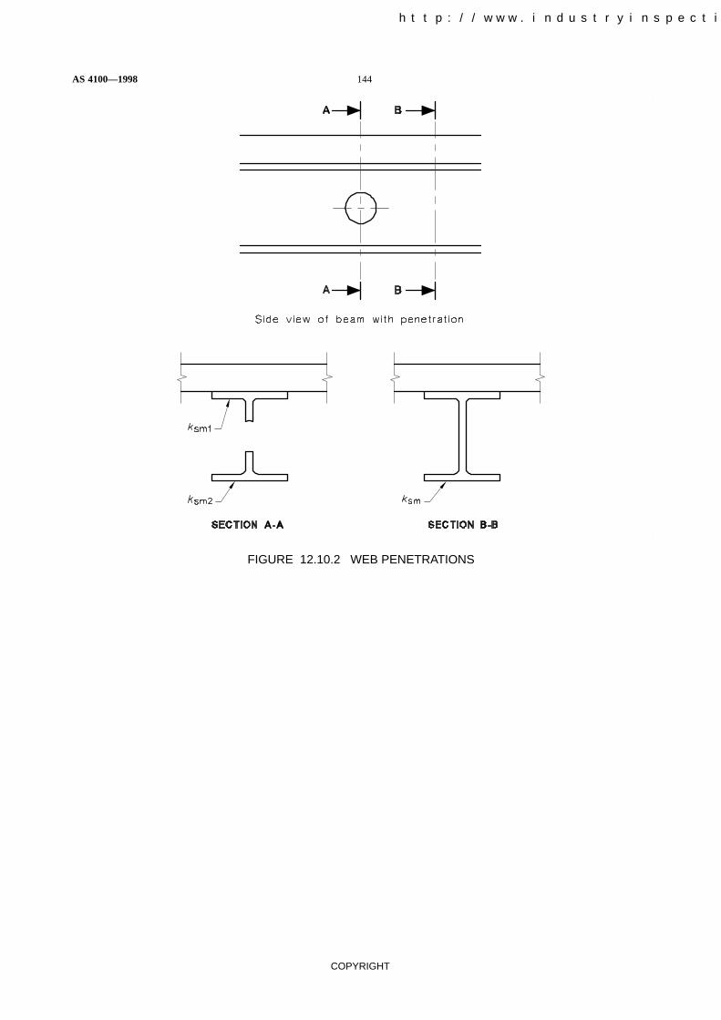
AS 4100—1998 144
COPYRIGHT
FIGURE 12.10.2 WEB PENETRATIONS
中国工业检验检测网 http://www.industryinspection.com

145 AS 4100—1998
COPYRIGHT
S E C T I O N 1 3 E A R T H Q U A K E
13.1 GENERAL This Section sets out the additional minimum design and detailing requirementsfor steel structures, structural members, and connections which form the whole or parts of a buildingor structure subject to the earthquake forces specified in AS 1170.4.
13.2 DEFINITIONS Definitions of the terms listed below and used herein are given inAS 1170.4—for the purpose of this Section, those definitions apply.
Bearing wall system
Braced frame
Building frame system
Concentric braced frame
Drift
Dual system
Ductility
Earthquake design category
Earthquake resisting system
Eccentric braced frame
Intermediate moment resisting frame
Moment resisting frame system
Ordinary moment resisting frame
Space frame
Special moment resisting frame
13.3 DESIGN AND DETAILING REQUIREMENTS
13.3.1 General Design and detailing requirements for a structure shall be based on the earthquakedesign category and structural system assigned to the structure in accordance with AS 1170.4.
A high stiffness element that is deemed not to be part of the horizontal force resisting system may beincorporated into a structure, provided its effects on the behaviour of the system are considered andprovided for in the analysis and design.
A non-structural element which is attached to or encloses the exterior of a structure shall be capableof accommodating the movements resulting from horizontal forces as follows:
(a) All connections and panel joints shall permit relative movement between storeys equal to thedeflection amplification factor (Kd) times the elastic storey drift calculated in accordance withAS 1170.4, or 6 mm, whichever is the greater.
(b) Connections shall be ductile and shall have a rotation capacity to preclude brittle failure.
(c) Connections which permit movements in the plane of a panel shall include sliding connectionsusing slotted or oversize holes, or connection details which permit movement by bending, orother connection details which have been demonstrated by test to be adequate.
13.3.2 Requirements for structures of earthquake Design Categories A and B Structures ofearthquake Design Categories A and B shall comply with the following;
(a) Horizontal resistance shall be provided in both principal directions.
(b) The minimum yield stress specified for the grade of steel shall not exceed 450 MPa.
中国工业检验检测网 http://www.industryinspection.com

AS 4100—1998 146
COPYRIGHT
13.3.3 Requirements for structures of earthquake Design Category C Regular structures ofearthquake Design Category C shall comply with the following:
(a) Horizontal resistance shall be provided in both principal directions.
(b) The minimum yield stress specified for the grade of steel shall not exceed 350 MPa.
Irregular structures of earthquake Design Category C shall comply with the detailing requirements ofearthquake Design Categories D and E.
13.3.4 Requirements for structures of earthquake Design Categories D and E
13.3.4.1 General The minimum yield stress specified for the grade of steel shall not exceed350 MPa.
13.3.4.2 Bearing wall and building frame systems Concentrically braced frames in bearing walland building frame systems shall comply with the following:
(a) The design axial force for each diagonal tension brace member shall be limited to 0.85 timesthe design tensile capacity. Connections of each diagonal brace member shall be designed forthe full member design capacity.
(b) Any web stiffeners in beam to column connections shall extend over the full depth betweenflanges and shall be butt welded to both flanges.
(c) Brace members in structures over two storeys shall be designed so that the compressivecapacity of the member is not less than 50% of the design tensile capacity.
(d) All welds shall be weld category SP in accordance with AS/NZS 1554.1. Welds shall besubjected to non-destructive examination as given in Table 13.3.4.2 and all suchnon-destructive examination shall comply with AS/NZS 1554.1.
NOTE: For the design of eccentrically braced frames, guidance may be obtained from NEHRP, NationalEarthquake Hazard Reduction Program, Recommended Provisions for the Development of SeismicRegulations for New Buildings, 1990, USA.
TABLE 13.3.4.2
MINIMUM REQUIREMENTS FOR NON-DESTRUCTIVE EXAMINATION
Weld typeVisual scanning
Visualexamination
Magnetic particle ordye penetrant
Ultrasonics orradiography
Weld type
% % % %
Butt welds in members orconnections in tension
100 100 100 10
Butt welds in members orconnections others thanthose in tension
100 50 10 2
All other welds inmembers or connections
100 20 5 2
13.3.4.3 Moment resisting frames The minimum yield stress specified for the grade of steel shallnot exceed 350 MPa.
There are no additional requirements for ordinary moment resisting frames:
Intermediate moment resisting frames shall comply with the following additional requirements;
(a) Any web stiffeners in beam to column connections shall extend over the full depth betweenflanges and shall be butt welded to both flanges.
中国工业检验检测网 http://www.industryinspection.com

147 AS 4100—1998
COPYRIGHT
(b) A member in which a plastic hinge will form during inelastic displacement of the frame shallcomply with the requirements for plastic analysis specified in Clause 4.5.
Special moment resisting frames shall comply with the following additional requirements:
(i) Any web stiffeners in beam to column connections shall extend over the full depth betweenflanges and shall be butt welded to both flanges.
(ii) A member in which a plastic hinge will form during inelastic displacement of the frame shallcomply with the requirements for plastic analysis specified in Clause 4.5.
(iii) Each rigid connection of a beam or girder to a column shall be capable of developing in thebeam or girder the design plastic moment capacity of the beam or girder, unless it can be shownthat an adequately ductile joint displacement capacity is provided by a lesser connection.However, the total design moment capacity of the connection shall not exceed the sum of thedesign plastic moment capacities of the column section above and below the joint.
If the ratio of the tensile strength to the yield stress specified for the grade of steel is lessthan 1.5, the members and connections shall be designed so that no plastic hinges form atlocations in which the beam flange area has been reduced locally, for example by notching.
(iv) All welds shall be comply with Clause 13.3.4.2(d).
(v) The effective length (le) of Clause 6.3.2 used in determining the slenderness ratio of an axiallyloaded compression member in a moment resisting frame shall be based on the assumption thatthe frame depends on its own bending stiffness for the horizontal stability of the structure, evenif bracing or shear walls are provided as part of a dual system.
(vi) A framing element deemed not to be part of the horizontal force resisting system shall eitherhave the capacity to resist additional bending moments induced by Kd times the elasticdisplacements resulting from the horizontal earthquake forces specified in AS 1170.4 orotherwise shall comply with detailing requirements of this Clause.
13.3.4.4 Dual systems The horizontal load resisting components of a dual system shall be detailedin accordance with the requirements specified in Clause 13.3.4 for the individual component.
13.3.4.5 Fabrication in an area of plastic deformation All areas of plastic deformation shallsatisfy the following:
(a) Edge In an area of a member or connection subject to plastic deformation, a sheared edgeshall not be permitted unless the edge is sheared oversize and machined to remove all signs ofthe sheared edge. A gas cut edge shall have a maximum surface roughness of 12 µm (CentreLine Average Method).
(b) Punching In an area subject to plastic deformation, fastener holes shall not be punched fullsize. If punched, holes shall be punched undersize and reamed or drilled to remove all thesheared surface.
13.4 DESIGN REQUIREMENTS FOR NON-BUILDING STRUCTURES Specificdetailing requirements are not provided for non-building structures. Details shall be adopted toensure a level of ductility consistent with the adopted structural response factor (Rf) and the form ofthe structural system.
中国工业检验检测网 http://www.industryinspection.com

AS 4100—1998 148
COPYRIGHT
S E C T I O N 1 4 F A B R I C A T I O N
14.1 GENERAL A fabricated item shall be liable to rejection if—
(a) the material does not satisfy the requirements of Clause 14.2;
(b) the fabrication does not satisfy the requirements of Clause 14.3; or
(c) it does not satisfy the tolerances specified in Clause 14.4.
The fabricated item may be accepted nonetheless if—
(i) it can be demonstrated that the structural adequacy and intended use of the item are notimpaired thereby; or
(ii) it passes testing in accordance with the appropriate Clauses of Section 17.
Fabricated items which do not satisfy either (i) or (ii) above and which do not satisfy eitherClause 14.2, Clause 14.3 or Clause 14.4 shall be rejected.
14.2 MATERIAL
14.2.1 General All material shall satisfy the requirements of the appropriate material Standardspecified in Clauses 2.2, 2.3 and 2.4.
Surface defects in the steel shall be removed using the methods specified in the appropriate Standardslisted in Clause 2.2.1.
14.2.2 Identification The steel grade shall be identifiable at all stages of fabrication, or the steelshall be classed as unidentified steel and only used in accordance with Clause 2.2.3. Any marking ofsteelwork shall be such as to not damage the material.
14.3 FABRICATION PROCEDURES
14.3.1 Methods All material shall be straightened or formed to the specified configuration bymethods that will not reduce the properties of the material below the values used in design. Steel maybe bent or pressed to the required shape by either hot or cold processes.
Local application of heat or mechanical means may be used to introduce or correct camber, sweepand out-of-straight. The temperature of heated areas shall not exceed 650°C.
14.3.2 Full contact splices Full contact splices may be produced by cold saw cutting ormachining.
The surfaces of such splices shall be such that, when the ends of the two members are abutted, thealignment of the members and the gap shall be within the tolerances specified in Clause 14.4.4.2.
14.3.3 Cutting Cutting may be by sawing, shearing, cropping, machining and thermal cuttingprocesses, as appropriate.
Shearing of items over 16 mm thick shall not be carried out when the item is to be galvanized andsubject to tensile force or bending moment unless the item is stress relieved subsequently.
Any cut surface not incorporated in a weld shall have a roughness not greater than the appropriatevalue given in Table 14.3.3. A cut surface to be incorporated in a weld shall comply withAS/NZS 1554.1.
中国工业检验检测网 http://www.industryinspection.com

149 AS 4100—1998
COPYRIGHT
TABLE 14.3.3
MAXIMUM CUT SURFACE ROUGHNESS
ApplicationMaximum
roughness, CLA�m
Normal applications, i.e. where the face and edgesremain as-cut or with minor dressing
25
Fatigue applications (Detail categories as defined inClause 11.5)
detail category � 80 MPa
detail category < 80 MPa
12
25
NOTES:
1 Roughness values may be estimated by comparison with surface replicas, such asthe WTIA. Flame Cut Surface replicas.
2 Suitable techniques of flame cutting are given in WTIA Technical Note 5.
3 CLA � Centre Line Average Method.
Cut surface roughness exceeding these values shall be repaired by grinding to give a value less thanthe specified roughness. Grinding marks shall be parallel to the direction of the cut.
Notches and gouges, not closer than 20t (where t is the component thickness) and not exceeding 1%of the total surface area on an otherwise satisfactory surface, are acceptable provided thatimperfections greater than t/5 but not exceeding 2 mm in depth are removed by machining orgrinding. Imperfections outside the above limits shall be repaired by welding in accordance withAS/NZS 1554.1.
A re-entrant corner shall be shaped notch free to a radius of at least 10 mm.
14.3.4 Welding Welding shall comply with AS/NZS 1554.1 or AS/NZS 1554.5 as appropriate(see Clause 11.1.5), and welding of studs shall comply with AS 1554.2.
14.3.5 Holing
14.3.5.1 General A round hole for a bolt shall either be machine flame cut, or drilled full size, orsubpunched 3 mm undersize and reamed to size, or punched full size.
A slotted hole shall be either machine flame cut, or punched in one operation, or formed by drillingtwo adjacent holes and completed by machine flame cutting.
Hand flame cutting of a bolt hole shall not be permitted except as a site rectification measure for holesin column base plates.
A punched hole shall only be permitted in material whose yield stress (fy) does not exceed 360 MPaand whose thickness does not exceed (5600/fy) mm.
14.3.5.2 Hole size The nominal diameter of a completed hole other than a hole in a base plate shallbe 2 mm larger than the nominal bolt diameter for a bolt not exceeding 24 mm in diameter, and notmore than 3 mm larger for a bolt of greater diameter.
For a hole in a base plate, the hole diameter shall be not more than 6 mm greater than the anchor boltdiameter. A special plate washer of minimum thickness 4 mm shall be used under the nut if the holediameter is 3 mm or more larger than the bolt diameter.
An oversize or slotted hole and the limitations on its use shall comply with the following:
(a) Oversize or slotted hole An oversize or slotted hole shall be permitted, provided that thefollowing requirements are satisfied:
(i) An oversize hole shall not exceed 1.25df or (df + 8) mm in diameter, whichever is thegreater, where df is the nominal bolt diameter, in millimetres.
中国工业检验检测网 http://www.industryinspection.com

AS 4100—1998 150
COPYRIGHT
(ii) A short slotted hole shall not exceed the appropriate hole size of this Clause in widthand 1.33df or (df + 10) mm in length, whichever is the greater.
(iii) A long slotted hole shall not exceed the appropriate hole size of this Clause in widthand 2.5df in length.
(b) Limitations on use The use of an oversize or slotted hole shall be limited so that the followingrequirements are satisfied:(i) Oversize hole An oversize hole may be used in any or all plies of bearing-type and
friction-type connections, provided hardened or plate washers are installed over theoversize hole under both the bolt head and the nut.
(ii) Short slotted hole A short slotted hole may be used in any or all plies of a friction-typeor a bearing-type connection, provided hardened or plate washers are installed over theholes under both the bolt head and the nut.In a friction-type connection subject to a shear force, a short slotted hole may be usedwithout regard to the direction of loading.In a bearing-type connection subject to a shear force, a short slotted hole may be usedonly where the connection is not eccentrically loaded and the bolt can bear uniformly,and where the slot is normal to the direction of the design action.
(iii) Long slotted hole A long slotted hole may be used only in alternate plies of either afriction-type or bearing-type connection, provided a plate washer not less than 8 mmthick is used to completely cover any long slotted hole under both the bolt head and thenut.In a friction-type connection subject to a shear force, a long slotted hole may be usedwithout regard to direction of loading.In a bearing-type connection subject to a shear force, a long slotted hole may be usedonly where the connection is not eccentrically loaded and where the bolt can bearuniformly, and where the slot is normal to the direction of the load.
14.3.6 Bolting
14.3.6.1 General All bolts and associated nuts and washers shall comply with the appropriate boltmaterial Standard specified in Clause 2.3.1. All material within the grip of the bolt shall be steel andno compressible material shall be permitted in the grip.The length of a bolt shall be such that at least one clear thread shows above the nut and at least onethread plus the thread run out is clear beneath the nut after tightening.One washer shall be provided under the rotated part.Where the slope of the surfaces of parts in contact with the bolt head or nut exceeds 1:20 with respectto a plane normal to the bolt axis, a suitably tapered washer shall be provided against the taperedsurface and the non-rotating part shall be placed against the tapered washer.The nuts used in a connection subject to vibration shall be secured to prevent loosening. (SeeClause 9.1.6)
14.3.6.2 Tensioned bolt A tensioned high strength bolt when installed during fabrication shall beinstalled in accordance with Clauses 15.2.4 and 15.2.5. The contact surfaces of a joint using atensioned bolt shall be prepared in accordance with Clause 14.3.6.3.
14.3.6.3 Preparation of surfaces in contact Preparation of surfaces in contact shall be as follows:(a) General All oil, dirt, loose scale, loose rust, burrs, fins and any other defects on the surfaces
of contact which will prevent solid seating of the parts in the snug-tight condition shall beremoved.
NOTES:1 If cleaning is necessary to meet these requirements, reference should be made to AS 1627.7.2 A clean ‘as-rolled’ surface with tight mill scale is acceptable without further cleaning.3 Snug-tight is defined in Clause 15.2.5.2.
中国工业检验检测网 http://www.industryinspection.com

151 AS 4100—1998
COPYRIGHT
(b) Friction-type connection For a friction-type connection, the contact surfaces shall be clean‘as-rolled’ surfaces or equivalent and, in addition to satisfying the provisions of Item (a), shallbe free from paint, lacquer, galvanizing or other applied finish unless the applied finish hasbeen tested in accordance with Appendix J to establish the friction coefficient (seeClause 9.3.3.2).
In a non-coated connection, paint including any overspray shall be excluded from areas closerthan one bolt diameter to any hole but not less than 25 mm from the edge of any hole and allareas within the bolt group.
(c) Bearing-type connection For a bearing-type connection, an applied finish on the contactsurfaces shall be permitted.
14.3.7 Pinned connection Pins and holes shall be finished so that the forces are distributed evenlyto the joint plies.
14.4 TOLERANCES
14.4.1 General The tolerance limits of this Clause shall be satisfied after fabrication is completedand any corrosion protection has been applied. Unless otherwise specified, the tolerance on allstructural dimensions shall be �2 mm.
14.4.2 Notation For the purpose of this Clause—
a0, a1 = out-of-square dimensions of flanges
a2, a3 = diagonal dimensions of a box section
b = lesser dimension of a web panel
bf = width of a flange
d = depth of a section
do = overall depth of a member including out-of-square dimensions
d1 = clear depth between flanges ignoring fillets or welds
e = web off-centre dimension
l = member length
�f = out-of-flatness of a flange plate
�v = deviation from verticality of a web at a support
�w = out-of-flatness of a web
14.4.3 Cross-section After fabrication, the tolerances on any cross-section of a rolled section or aplate shall be those specified in AS/NZS 3678 or AS/NZS 3679.1, as appropriate, in respect of depth,flange width, flange thickness, web thickness, out-of-square, and web off-centre.
For any built-up section, the deviations from the specified dimensions of the cross-section shall notexceed the following:
(a) Depth of a section (d) (see Figure 14.4.3(1))
for d � 900, �3 mm
for 900 < d � 1800, � �3 (d � 900)
300� mm
for d > 1800, �6 mm
(b) Width of a flange (bf) (see Figure 14.4.3(1))
for all bf, �6 mm
中国工业检验检测网 http://www.industryinspection.com

AS 4100—1998 152
COPYRIGHT
(c) Out-of-square of an individual flange (a0 or a1) (see Figure 14.4.3(1))
for bf � 600 mm, �3 mm
for bf > 600 mm, � � bf
200� mm
(d) Total out-of-square of two flanges (a0 + a1) (see Figure 14.4.3(1))
for bf � 600 mm, �6 mm
for bf > 600 mm, � � bf
100� mm
NOTES:
1 Dimension d, do, ao and a1 are measured parallel to the centreline of the web. Dimensions bf and(0.5bf � e) are measured parallel to the plane of the flange.
2 Dimesions d is measured at the centreline of the web.
FIGURE 14.4.3(1) TOLERANCES ON A CROSS-SECTION
(e) Out-of-flatness a of web (�w) (see Figure 14.4.3(2))
d1/150 mm for unstiffened web,
b/100 mm for stiffened web with intermediate stiffeners,
measured on a gauge length in the direction of d1 or b, as appropriate.
(f) Deviation from verticality of a web at a support (�v) (see Figure 14.4.3(2))
for d � 900 mm, �3 mm
for d > 900 mm, � � d200� mm
中国工业检验检测网 http://www.industryinspection.com

153 AS 4100—1998
COPYRIGHT
FIGURE 14.4.3(2) TOLERANCES ON A WEB
(g) Tolerance on shape of a built-up box section (see Figure 14.4.3.(3))
A built-up box section shall not deviate at the diaphragm from the prescribed shape by morethan�5 mm or �[(a2 + a3)/400] mm, whichever is greater, unless connection requirementsnecessitate more stringent tolerances.
FIGURE 14.4.3(3) TOLERANCE ON SHAPE OF A BOX SECTION
(h) Off-centre of a web (e) (see Figure 14.4.3(4)) �6 mm
FIGURE 14.4.3(4) TOLERANCE ON OFF-CENTRE OF A WEB
中国工业检验检测网 http://www.industryinspection.com

AS 4100—1998 154
COPYRIGHT
(j) Out-of-flatness of a flange (�f) (see Figure 14.4.3(5))
for bf � 450 mm � � br
150� mm
for bf > 450 mm �3 mm
FIGURE 14.4.3(5) TOLERANCE ON OUT-OF-FLATNESS OF A FLANGE
14.4.4 Compression member
14.4.4.1 Straightness A member shall not deviate about either principal axis from a straight linedrawn between end points by an amount exceeding l/1000 or 3 mm whichever is the greater.
14.4.4.2 Full contact splice If the ends of two butting lengths of a member, or the end of a memberand the contact face of an adjoining cap plate or baseplate, are required to be in full contact, such arequirement shall be deemed to be satisfied if the bearing surfaces are prepared so that when theabutting member length or lengths are aligned to within the tolerance specified in Clause 15.3.3, themaximum clearance between the abutting surfaces shall not exceed 1 mm, and shall also not exceed0.5 mm over at least 67% of the contact area.
14.4.4.3 Length The length of a member shall not deviate from its specified length by more than�2 mm.
14.4.5 Beam
14.4.5.1 Straightness A beam shall not deviate from a straight line drawn between the ends of thebeam by more than the following:
(a) Camber—measured with the web horizontal on a test surface (see Figure 14.4.5.1(a)). Thetolerance on specified camber shall not exceed l/1000 or 10 mm whichever is the lesser.
(b) Sweep—measured with the web vertical (see Figure 14.4.5.1(b)). The sweep in plan shall notexceed l/1000 or 3 mm whichever is the greater.
14.4.5.2 Length The length of a beam shall not deviate from its specified length by more than�2 mm for lengths less than 10 m, and �4 mm for lengths greater than 10 m.
14.4.6 Tension member
14.4.6.1 Straightness A member shall not deviate from a straight line drawn between end points bymore than l/500, where l is the length between end points.
14.4.6.2 Length The length of a tension member shall not deviate from its specified length by morethan�2 mm for lengths less than 10 m, and �4 mm for lengths greater than 10 m.
中国工业检验检测网 http://www.industryinspection.com

155 AS 4100—1998
COPYRIGHT
FIGURE 14.4.5.1 MEASUREMENT OF CAMBER AND SWEEP
中国工业检验检测网 http://www.industryinspection.com

AS 4100—1998 156
COPYRIGHT
S E C T I O N 1 5 E R E C T I O N
15.1 GENERAL
15.1.1 Rejection of an erected item An erected item shall be liable to rejection if—
(a) the erection does not satisfy the requirements of Clause 15.2; or
(b) it does not satisfy the tolerances specified in Clause 15.3.
The erected item may be accepted nonetheless if—
(i) it can be demonstrated that the structural adequacy and intended use of the item are notimpaired thereby; or
(ii) it passes testing in accordance with the appropriate clauses of Section 17.
Erected items which do not satisfy either (i) or (ii) above and which do not satisfy either Clause 15.2or 15.3 shall be rejected.
Bolts, nuts and washers shall be liable to rejection if, in the erected structure, they do not comply withClauses 14.3.6, 15.2.3, 15.2.4 and 15.2.5, unless it can be demonstrated that the structural adequacyand intended use of the item are not impaired thereby.
Grouting at supports which does not satisfy the requiremets of Clause 15.5 shall be rejected.
15.1.2 Safety during erection During the erection of a structure, steelwork shall be made safeagainst erection loading, including loading due to erection equipment or its operation, and wind.
15.1.3 Equipment support Equipment supported on partly erected steelwork shall not induceactions in the steel greater than the design capacities permitted in this Standard.
15.1.4 Reference temperature Dimensions shall be set out on the basis of a referencetemperature of 20 degrees Celsius.
15.2 ERECTION PROCEDURES
15.2.1 General The requirements specified in Clause 14.3 shall also be observed during theerection of the steel frame and during any modifications to the steelwork in the course of erection.
This requirement shall apply to the following:
(a) Full contact splices (see Clause 14.3.2).
(b) Cutting (see Clause 14.3.3).
(c) Welding (see Clause 14.3.4).
(d) Holing (see Clause 14.3.5).
(e) Bolting (see Clause 14.3.6).
Throughout the erection of the structure, the steelwork shall be securely bolted or fastened to ensurethat it can adequately withstand all loadings liable to be encountered during erection, including,where necessary, those from erection plant and its operation. Any temporary bracing or temporaryrestraint shall be left in position until such time as erection is sufficiently advanced as to allow its saferemoval.
All connections for temporary bracing and members to be provided for erection purposes shall bemade in such a manner as not to weaken the permanent structure or to impair its serviceability. Allwelding of such connections and their removal shall be in accordance with AS/NZS 1554.1.

157 AS 4100—1998
COPYRIGHT
15.2.2 Delivery, storage and handling Members, components and fasteners shall be handled andstacked in such a way that damage is not caused to them. Means shall be provided to minimizedamage to the corrosion protection on the steelwork.
All work shall be protected from damage in transit. Particular care shall be taken to stiffen free ends,prevent permanent distortion, and adequately protect all surfaces prepared for full contact splices.All bolts, nuts, washers, screws, small plates and articles generally shall be suitably packed andidentified.
15.2.3 Assembly and alignment All matching holes shall align with each other so that a gauge ordrift, equal in diameter to that of the bolts, shall pass freely through the assembled contact faces atright angles to them. Drifting to align holes shall be done in a manner that will not distort the metal norenlarge the holes.
Each part of the structure shall be aligned as soon as practicable after it has been erected. Permanentconnections shall not be made between members until sufficient of the structure has been aligned,levelled, plumbed and temporarily connected to ensure that members will not be displaced duringsubsequent erection or alignment of the remainder of the structure.
Each bolt and nut shall be assembled with at least one washer. A washer shall be placed under therotating component. Where the slope of the surfaces of parts in contact with the bolt head or nutexceeds 1:20 with respect to a plane normal to the bolt axis, a suitable tapered washer shall be usedagainst the sloping surface. The non-rotating component shall be placed against the tapered washer.
Bolting categories 4.6/S and 8.8/S shall be installed to the snug-tight condition specified inClause 15.2.5.2(a).
Hardened or plate washers shall be used under both the bolt head and nut for any slotted and oversizeholes as specified in Clause 14.3.5.2(b).
15.2.4 Assembly of a connection involving tensioned bolts
15.2.4.1 Placement of a nut The nut shall be placed so that the mark specified in AS/NZS 1252 toidentify a high strength nut is visible after tightening.
15.2.4.2 Packing Packing shall be provided wherever necessary to ensure that theload-transmitting plies are in effective contact when the connection is tightened to the snug-tightcondition defined in Clause 15.2.5.2(a). All packing shall be steel with a surface condition similar tothat of the adjacent plies.
15.2.4.3 Tightening pattern Snug-tightening and final tensioning of the bolts in a connection shallproceed from the stiffest part of the connection towards the free edges.
High strength structural bolts that are to be tensioned may be used temporarily during erection tofacilitate assembly, but if so used they shall not be finally tensioned until all bolts in the connectionhave been snug-tightened in the correct sequence.
15.2.4.4 Retensioning Retensioning of bolts which have been fully tensioned shall be avoided,except that if retensioning is carried out, it shall only be permitted once and only where the boltremains in the same hole in which it was originally tensioned and with the same grip.
Retensioning of galvanized bolts shall not be permitted.
Under no circumstances shall bolts which have been fully tensioned be reused in another hole.
Touching up or retensioning of previously tensioned bolts which may have been loosened by thetensioning of adjacent bolts shall not be considered as retensioning.
中国工业检验检测网 http://www.industryinspection.com中国工业检验检测网 http://www.industryinspection.com

AS 4100—1998 158
COPYRIGHT
15.2.5 Methods of tensioning
15.2.5.1 General The method of tensioning shall be in accordance with either Clause 15.2.5.2 orClause 15.2.5.3.
In the completed connection, all bolts shall have at least the minimum bolt tension specified inTable 15.2.5.1 when all bolts in the bolt group are tightened.
TABLE 15.2.5.1
MINIMUM BOLT TENSION
Nominal diameterof bolt
Minimum bolt tensionkN
M16
M20
M24
M30
M36
95
145
210
335
490
NOTE: The minimum bolt tensions given in this Table areapproximately equivalent to the minimum proof loads given inAS/NZS 1252.
15.2.5.2 Part-turn method of tensioning Tensioning of bolts by the part-turn method shall be inaccordance with the following procedure:
(a) On assembly, all bolts in the connection shall be first tightened to a snug-tight condition toensure that the load-transmitting plies are brought into effective contact.
Snug-tight is the tightness attained by a few impacts of an impact wrench or by the full effort ofa person using a standard podger spanner.
(b) After completing snug-tightening, location marks shall be established to mark the relativeposition of the bolt and the nut and to control the final nut rotation.
Observation of the final nut rotation may be achieved by using marked wrench sockets, butlocation marks shall be permanent when required for inspection.
(c) Bolts shall be finally tensioned by rotating the nut by the amount given in Table 15.2.5.2.During the final tensioning, the component not turned by the wrench shall not rotate.
中国工业检验检测网 http://www.industryinspection.com

159 AS 4100—1998
COPYRIGHT
TABLE 15.2.5.2
NUT ROTATION FROM THE SNUG-TIGHT CONDITION
Bolt lengthi
Disposition of outer face of bolted parts(see Notes 1, 2, 3 and 4)
(underside of head to
end of bolt)Both facesnormal tobolt axis
One face normal tobolt axis and other
slopedBoth faces sloped
Up to and including4 diameters
1/3 tur n 1/2 tur n 2/3 tur n
Over 4 diameters butnot exceeding8 diameters
1/2 tur n 2/3 tur n 5/6 tur n
Over 8 diameters butnot exceeding12 diameters (see Note 5)
2/3 tur n 5/6 tur n 1 tur n
NOTES:
1 Tolerance on rotation: for 1/2 turn or less, one-twelfth of a turn (30°) over and nil under tolerance; for 2/3turn or more, one-eighth of a turn (45°) over and nil under tolerance.
2 The bolt tension achieved with the amount of nut rotation specified in Table 15.2.5.2 will be at least equalto the minimum bolt tension specified in Table 15.2.5.1.
3 Nut rotation is the rotation relative to the bolt, regardless of the component turned.
4 Nut rotations specified are only applicable to connections in which all material within the grip of the boltis steel.
5 No research has been performed to establish the turn-of-nut procedure for bolt lengths exceeding12 diameters. Therefore, the required rotation should be determined by actual test in a suitable tensionmeasuring device which simulates conditions of solidly fitted steel.
15.2.5.3 Tensioning by use of direct-tension indication device Tensioning of bolts using adirect-tension indication device shall be in accordance with the following procedure:
(a) The suitability of the device shall be demonstrated by testing a representative sample of notless than three bolts for each diameter and grade of bolt in a calibration device capable ofindicating bolt tension. The calibration test shall demonstrate that the device indicates atension not less than 1.05 times the minimum bolt tension specified in Table 15.2.5.1.
(b) On assembly, all bolts and nuts in the connection shall be first tightened to a snug-tightcondition defined in Clause 15.2.5.2(a).
(c) After completing snug-tightening, the bolt shall be tensioned to provide the minimum bolttension specified in Clause 15.2.5.1. This shall be indicated by the tension indication device.
NOTE: Tensioning of bolts using a direct-tension indication device should also be in accordance with themanufacturer’s specification.
15.3 TOLERANCES
15.3.1 Location of anchor bolts Anchor bolts shall be restrained in position both in a vertical anda horizontal direction during all setting-in operations.
Anchor bolts shall be set out in accordance with the erection drawings. They shall not vary from thepositions shown on the erection drawings by more than the following: (See Figure 15.3.1.)
(a) 3 mm centre-to-centre of any two bolts within an anchor bolt group, where an anchor boltgroup is defined as the set of anchor bolts which receives a single fabricated steel member.
中国工业检验检测网 http://www.industryinspection.com

AS 4100—1998 160
COPYRIGHT
(b) 6 mm centre-to-centre of adjacent anchor bolt groups.
(c) Maximum accumulation of 6 mm per 30 000 mm along an established column line of multipleanchor bolt groups, but not to exceed a total of 25 mm. The established column line is the actualfield line most representative of the centres of the as-built anchor bolt groups along a line ofcolumns.
(d) 6 mm from the centre of any anchor bolt group to the established column line through thatgroup.
Anchor bolts shall be set perpendicular to the theoretical bearing surface, threads shall be protectedand free of concrete and nuts shall run freely on the threads.
The projection of the end of the anchor bolt from the theoretical bearing surface shall not be more than25 mm longer nor 5 mm shorter than that specified.
FIGURE 15.3.1 TOLERANCES IN ANCHOR BOLT LOCATION
15.3.2 Column base
15.3.2.1 Position in plan The position in plan of a steel column base shall not deviate from itscorrect value by more than 6 mm along either of the principal setting out axes.
15.3.2.2 Level The level of the underside of a steel base plate shall not deviate from its correctvalue by more than �10 mm.
中国工业检验检测网 http://www.industryinspection.com

161 AS 4100—1998
COPYRIGHT
15.3.2.3 Full contact If full contact is specified, the requirements of Clause 14.4.4.2 shall besatisfied, unless shims are used to reduce the measureable gaps to values specified in Clause 14.4.4.2.
Packs, shims and other supporting devices shall be flat and of the same steel grade as the member. Ifsuch packings are to be subsequently grouted, they shall be placed so that the grout totally enclosesthem with a minimum cover of 50 mm.
15.3.3 Plumbing of a compression member The alignment and plumbing of a compressionmember shall be in accordance with both of the following requirements:
(a) The deviation of any point above the base of the compression member from its correct positionshall not exceed height/500 or as follows, whichever is the lesser:
(i) For a point up to 60 m above the base of the member 25 mm.. . . . . . . . . . . . . . . . .
(ii) For a point more than 60 m above the base of the member . . . . . . . . . . . . . . . . . . . 25 mm plus 1 mm for every 3 m in excess of 60 m up to a maximum of. . . . . . . . .
50 mm.
(b) The deviation of the top of the compression member from its correct position relative to thebottom of the member from one storey to the next shall not exceed storey height/500.
15.3.4 Column splice A column splice shall conform to the following requirements:
(a) The level of the centre-line of a column splice shall not deviate from its correct level by morethan �10 mm.
(b) The position in plan of a column splice shall be in accordance with the plumbing tolerancesspecified in Clause 15.3.3.
(c) The plan position of each spliced member relative to the other shall not deviate by more than2 mm from its correct position along either of the principal setting-out axes.
15.3.5 Level and alignment of a beam In erecting a structure, a beam shall be deemed to becorrectly positioned when—
(a) all connections including splices are completed;
(b) the maximum sweep in the beam is less than lb/500, where lb is the length between points ofeffective bracing or restraint;
(c) a beam is within �10 mm of its correct level at connections to other members; and
(d) a web of a beam is within �3 mm horizontally of its correct position at connections to othermembers.
15.3.6 Position of a tension member A tension member shall not deviate from its correct positionrelative to the members to which it is connected by more than 3 mm along any setting-out axis.
15.3.7 Overall building dimensions The overall building dimensions shall not deviate from thecorrect values by more than the following:
(a) Length (see Figure 15.3.7.1)
for Σlc �30 m, Σ�lc � �20 mm
for Σlc > 30 m, Σ�lc � �{20 mm + 0.25(Σlc – 30) mm}
(b) Height (see Figure 15.3.7.2)
for Σhb�30 m, Σ�hb � �20 mm
for Σhb >30 m, Σ�hb � �{20 mm + 0.25(Σhb – 30) mm}
provided that—
(i) the distance between adjacent steel column centres (lc) at every section does not deviate bymore than �15 mm from the correct length;
中国工业检验检测网 http://www.industryinspection.com

AS 4100—1998 162
COPYRIGHT
(ii) the vertical distance between tops of beams (hb) at every section does not deviate by more than�20 mm from the correct values; and
(iii) all other tolerances in this Section are complied with.
For the purposes of this Clause—
Σlc = the correct overall length of steelwork, being the centre-to-centre distance of the extremecolumns as shown in Figure 15.3.7.1, at any location along the building, and
Σhb= the correct overall height of steelwork, being the vertical distance from underside ofcolumn baseplate to the top of the finished floor level shown in Figure 15.3.7.2, at anylocation along the building.
FIGURE 15.3.7.1 DEVIATIONS IN LENGTH (VERTICAL SECTION)
FIGURE 15.3.7.2 DEVIATIONS IN HEIGHT (VERTICAL SECTION)
中国工业检验检测网 http://www.industryinspection.com

163 AS 4100—1998
COPYRIGHT
15.4 INSPECTION OF BOLTED CONNECTIONS
15.4.1 Tensioned bolts The methods of tensioning specified in Clause 15.2.5 shall comply withthe following requirements:
(a) Part-turn tensioning—the correct part-turn from the snug-tight position shall be measured orobserved.
(b) Direct-tensioning indication device—the minimum tension developed in the bolt shall beindicated directly by the device.
NOTES:
1 The manufacturer’s recommendations for inspection procedures should be followed when using adirect-tensioning indication device.
2 The use of a torque wrench for inspection is considered suitable only to detect gross undertensioning. Aprocedure for such use is detailed in Appendix K.
15.4.2 Damaged items Bolts, nuts and washers which, on visual inspection, show any evidence ofphysical defects shall be removed and replaced by new items.
15.5 GROUTING AT SUPPORTS
15.5.1 Compression member base or beam Bedding under a compression member base plate ora bearing of a beam on masonry and concrete shall be provided by grout or mortar.
Grouting or packing shall not be carried out until a sufficient portion of the structure (for multistoreybuildings, a sufficient number of bottom column lengths) has been aligned, levelled and plumbed andadequately braced by other structural members which have been levelled and are securely held bytheir permanent fastenings. Steel packing or levelling nuts on the anchor bolts shall be under the baseplate to support the steelwork. The space under the steel shall be thoroughly cleaned and be free frommoisture immediately before grouting.
15.5.2 Grouting Grout shall completely fill the space to be grouted and shall either be placedunder pressure or placed by ramming against fixed supports.
Grout shall comply with AS 3600.
中国工业检验检测网 http://www.industryinspection.com

AS 4100—1998 164
COPYRIGHT
S E C T I O N 1 6 M O D I F I C A T I O N O F E X I S T I N GS T R U C T U R E S
16.1 GENERAL All provisions of this Standard apply equally to the modification of existingstructures or parts of a structure except as modified in this Section.
16.2 MATERIALS The types of base metal involved shall be determined before preparing thedrawings and specifications covering the strengthening of, the repair of, or the welding proceduresfor an existing structure or parts of a structure.
16.3 CLEANING Surfaces of existing material, which are to be strengthened, repaired, orwelded shall be cleaned of dirt, rust, and other foreign matter except adherent surface protection. Theportions of such surfaces that are to be welded shall be cleaned thoroughly of all foreign matter,including paint film, for a distance of 50 mm from each side of the outside lines of the welds.
16.4 SPECIAL PROVISIONS
16.4.1 Welding and cutting The capacity of a member to carry loads while welding or oxygencutting is being performed on it shall be determined in accordance with to the provisions of thisStandard, taking into consideration the extent of cross-section heating of the member which resultsfrom the operation that is being performed.
16.4.2 Welding sequence The welding sequence shall be chosen so as to minimize distortion ofthe member and ensure that its straightness remains within the appropriate straightness limits ofClauses 14.4.3, 14.4.4, 14.4.5 and 14.4.6.
中国工业检验检测网 http://www.industryinspection.com

165 AS 4100—1998
COPYRIGHT
S E C T I O N 1 7 T E S T I N G O F S T R U C T U R E S O R E L E M E N T S
17.1 GENERAL
17.1.1 Scope of Section The methods of test given in this Section are applicable to proof tests andprototype tests of complete structures, sub-structures, individual members or connections. Themethods are not applicable to the testing of structural models, nor to the establishment of generaldesign criteria or data.
17.1.2 Circumstances requiring tests Structures or parts of structures designed in accordancewith this Standard are not required to be tested. Tests may be accepted as an alternative to calculationor may become necessary in special circumstances.
17.2 DEFINITIONS For the purposes of this Section, the definitions below apply.
Proof testing—the application of test loads to a structure, sub-structure, member or connection toascertain the structural characteristics of only that one unit under test.
Prototype testing—the application of test loads to one or more structures, sub-structures, members orconnections to ascertain the structural characteristics of that class of structures, sub-structures,members or connections which are nominally identical to the units tested.
17.3 TEST REQUIREMENTS The test load shall be determined in accordance withClause 17.4.2 or Clause 17.5.2, as appropriate.
Loading devices shall be calibrated, and care shall be exercised to ensure that no artificial restraintsare applied by the loading systems. The test load shall be applied to the unit at a rate as uniform aspracticable. The distribution and duration of forces applied in the test shall represent those forces towhich the structure is deemed to be subjected under the requirements of Section 3.
Deformations shall, as a minimum requirement, be recorded at the following times:
(a) Prior to the application of the test load.
(b) After the test load has been applied.
(c) After the removal of the test load.
17.4 PROOF TESTING
17.4.1 Application This Clause applies to the testing of a structure, sub-structure, member orconnection to determine whether that particular structure, sub-structure, member or connectioncomplies with the requirements for the strength or serviceability limit state, as appropriate.
17.4.2 Test load The test load shall be equal to the design load for the relevant limit state asdetermined from Clause 3.2.3.
17.4.3 Criteria for acceptance Criteria for acceptance shall be as follows:
(a) Acceptance for strength The test structure, sub-structure, member or connection shall bedeemed to comply with the requirements for strength if it is able to sustain the strength limitstate test load for at least 15 minutes. It shall then be inspected to determine the nature andextent of any damage incurred during the test. The effects of the damage shall be consideredand, if necessary, appropriate repairs to the damaged parts carried out.
(b) Acceptance for serviceability The maximum deformation of the structure or member underthe serviceability limit state test load shall be within the serviceability limits appropriate to thestructure.
中国工业检验检测网 http://www.industryinspection.com

AS 4100—1998 166
COPYRIGHT
17.5 PROTOTYPE TESTING
17.5.1 Test specimen The materials and fabrication of the prototype shall comply with Sections 2and 14, respectively. Any additional requirements of a manufacturing specification shall be compliedwith and the method of erection used shall simulate that which will be used in production.
17.5.2 Test load The test load shall be equal to the design load for the relevant limit statedetermined in accordance with Clause 3.2.3, multiplied by the appropriate factor given inTable 17.5.2, unless a reliability analysis shows that a smaller value can be adopted.
17.5.3 Criteria for acceptance Criteria for acceptance shall be as follows:
(a) Acceptance for strength The test unit shall be deemed to comply with the requirements forstrength if it is able to sustain the strength limit state test load for at least 5 minutes.
(b) Acceptance for serviceability The maximum deformation of the unit under the serviceabilitylimit state test load shall be within the serviceability limits appropriate to the structure.
17.5.4 Acceptance of production units Production-run units shall be similar in all respects to theunit or units tested.
TABLE 17.5.2
FACTORS TO ALLOW FOR VARIABILITY OF STRUCTURAL UNITS
No of similarunits to be
testedStrength limit state Serviceability limit state
1
2
3
1.5
1.4
1.3
1.2
1.2
1.2
4
5
10
1.3
1.3
1.2
1.1
1.1
1.1
17.6 REPORT OF TESTS The report of the test on each unit shall contain, in addition to the testresults, a clear statement of the conditions of testing, including the method of loading and ofmeasuring deflection, together with any other relevant data. The report shall also contain a statementas to whether or not the structure or part tested satisfies the acceptance criteria.
中国工业检验检测网 http://www.industryinspection.com

167 AS 4100—1998
COPYRIGHT
APPENDIX A
REFERENCED DOCUMENTS
(Normative)
The following documents are referred to in this Standard:
AS
1101 Graphical symbols for general engineering1101.3 Part 3: Welding and non-destructive examination1163 Structural steel hollow sections1170 Minimum design loads on structures (known as the SAA Loading Code)1170.1 Part 1: Dead and live loads and load combinations1170.2 Part 2: Wind loads1170.3 Part 3: Snow loads1170.4 Part 4: Earthquake loads1210 Pressure vessels1275 Metric screw threads for fasteners1391 Methods for tensile testing of metals1418 Cranes (including hoists and winches)1418.1 Part 1: General requirements1418.3 Part 3: Bridge, gantry and portal cranes (including container cranes)1418.5 Part 5: Mobile and vehicle-loading cranes1530 Methods for fire tests on building materials, components and structures1530.4 Part 4: Fire-resistance tests of elements of building construction1554 Structural steel welding1554.2 Part 2: Stud welding (Steel studs to steel)1657 Fixed platforms, walkways, stairways and ladders—Design, construction and
installation1735 Lifts, escalators and moving walks (known as the SAA Lift Code)1735.1 Part 1: General requirements1858 Electrodes and fluxes for submerged-arc welding1858.1 Part 1: Carbon steels and carbon-manganese steels2074 Steel castings2203 Cored electrodes for arc-welding2205 Methods of destructive testing of welds in metal2205.2.1 Part 2.1: Transverse butt tensile test2214 Certification of welding supervisors—Structural steel welding2327 Composite structures2370.1 Part 1: Simply supported beams2670 Evaluation of human exposure to whole-body vibration2670.1 Part 1: General requirements2670.2 Part 2: Continuous and shock-induced vibration in buildings (1 to 80 Hz)3600 Concrete structures
AS/NZS
1110 ISO metric precision hexagon bolts and screws1111 ISO metric commercial hexagon bolts and screws1112 ISO metric hexagon nuts, including thin nuts, slotted nuts and castle nuts
中国工业检验检测网 http://www.industryinspection.com

AS 4100—1998 168
COPYRIGHT
AS/NZS
1252 High strength steel bolts with associated nuts and washers for structuralengineering
1553 Covered electrodes for welding1553.1 Part 1: Low carbon steel electrodes for manual metal-arc welding of carbon
steels and carbon-manganese steels1554 Structural steel welding1554.1 Part 1: Welding of steel structures1554.5 Part 5: Welding of steel structures subject to high levels of fatigue loading1559 Hot–dip galvanized steel bolts with associated nuts and washers for tower
construction1594 Hot-rolled steel flat products1873 Powder-actuated (PA) hand-held fastening tools1873.1 Part 1: Selection, operation and maintenance1873.2 Part 2: Design and construction1873.3 Part 3: Charges1873.4 Part 4: Fasteners2717 Welding—Electrodes—Gas metal arc2717.1 Part 1: Ferritic steel electrodes3678 Structural steel—Hot-rolled plates, floorplates and slabs3679 Structural steel3679.1 Part 1: Hot-rolled bars and sections3679.2 Part 2: Welded I sections
SAA
HB77 Australian Bridge Design CodeHB77.2 Part 2: Design loadsHB77.8 Part 8: Railway SupplementPD 6493—1991 Guidance on Some Methods for the Derivation of Acceptance Levels for Defects
in Fusion Welded Joints, HMSOWTIA Technical Note 5 ‘Flame Cutting of Steels’ 1994
中国工业检验检测网 http://www.industryinspection.com

169 AS 4100—1998
COPYRIGHT
APPENDIX B
SUGGESTED DEFLECTION LIMITS
(Informative)
B1 SUGGESTED VERTICAL DEFLECTION LIMITS FOR BEAMS The verticaldeflection of beams may be controlled using the suggested limits given in Table B1.
TABLE B1
SUGGESTED LIMITS ON CALCULATED VERTICAL DEFLECTIONS OF BEAMS
Type ofbeam
Deflection tobe considered
Deflection limit (�)for span (l)(See Note 1)
Deflection limit (�)for cantilever (l)
(See Note 2)
Beam supportingmasonry partitions
The deflection whichoccurs after theaddition or attachmentof partitions
�l� 1
500
where provision is made tominimize the effect ofmovement, otherwise
�l� 1
1000�
l�
1500
�l� 1
250
where provision is made tominimize the effect ofmovement, otherwise
All beams The total deflection �
l�
1250
�
l�
1125
NOTES:
1 Suggested deflection limits in this Table may not safeguard against ponding.
2 For cantilevers, the values of �/l given in this Table apply, provided that the effect of the rotation at the support isincluded in the calculation of �.
B2 SUGGESTED HORIZONTAL DEFLECTION LIMITS The relative horizontaldeflection between adjacent frames at the eaves level of industrial buildings due to wind loads may becontrolled by using the following suggested limits:
(a) Building clad in steel or aluminium sheeting without gantry cranes and without internal
partitions against external wallscolumn height
150. . . . . . . . . . . . . . . . . . . . . . . . . . . . . . . . . .
(b) Building with masonry walls supported by steelworkcolumn height
240. . . . . . . . . . . . . . . . .
中国工业检验检测网 http://www.industryinspection.com

AS 4100—1998 170
COPYRIGHT
APPENDIX C
CORROSION PROTECTION
(Informative)
C1 SCOPE This Appendix applies to the corrosion protection of steel members and connectioncomponents.
C2 SYSTEMS Recommendations for the painting of steelwork installed within buildingstructures and not exposed to rain or sun may be found in AS 2311. For other steelwork, includingsteelwork requiring long-life protection, recommendations on protection systems may be found inAS/NZS 2312.
The type of coating and surface preparation should be specified, after proper account has been takenof the use of the structure, climatic or other local conditions, maintenance provisions, and of theeffects of the fabrication processes on previously applied coatings.
C3 STANDARDS All steelwork which is to be painted after fabrication and before erectionshould be prepared and painted in accordance with the relevant Standards. A list of such Standardsmay be found in Paragraph C7.
C4 INACCESSIBLE SURFACES Surfaces which will be in contact or near contact afterfabrication or erection should receive their specified surface preparation and treatment prior toassembly. Such surfaces should be dry before assembly.
This Paragraph does not apply to the interior of hollow sections conforming to AS 1163, or boxsections, or connection surfaces for joints with friction type bolting category where bare steelinterfaces are specified.
C5 PROTECTION DURING TRANSPORT AND HANDLING AFTER CORROSIONPROTECTION Structural members should be adequately protected during handling and transportto prevent damage to the corrosion protection. Units which are transported in nested bundles shouldbe separable without damage to the units or their coatings. Care should be taken when handling longunits or bundles. Consideration should be given to the use of lifting beams with appropriately spacedlifting points and slings, or to lifting with properly spaced fork-lift tines.
C6 REPAIRS TO CORROSION PROTECTION Corrosion protection which has beendamaged by welding or other causes should be restored before the structure is put into service. Thedamaged area should be dry and clean, free from dirt, grease, loose or heavy scale or rust before thecorrosion protection is applied. The corrosion protection should be applied as soon as practicable andbefore noticeable oxidation of cleaned surfaces occurs. Damaged zinc coating should be restored by asuitable zinc paint.
C7 RELEVANT STANDARDS
AS
1192 Electroplated coatings—Nickel and chromium1214 Hot-dip galvanized coatings and threaded fasteners (ISO metric coarse thread
series)1580 Paints and related materials—Methods of test1580.481.1.9 Method 481.1.9: Exposed to weathering—Degree of blistering1627 Metal finishing—Preparation and pretreatment of surfaces1627.0 Part 0: Method selection guide1627.1 Part 1: Cleaning using liquid solvents and alkaline solutions1627.2 Part 2: Power tool cleaning
中国工业检验检测网 http://www.industryinspection.com
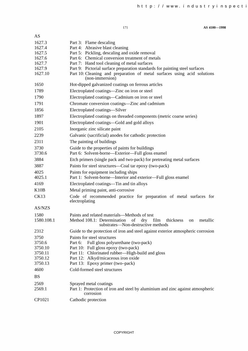
171 AS 4100—1998
COPYRIGHT
AS
1627.3 Part 3: Flame descaling1627.4 Part 4: Abrasive blast cleaning1627.5 Part 5: Pickling, descaling and oxide removal1627.6 Part 6: Chemical conversion treatment of metals1627.7 Part 7: Hand tool cleaning of metal surfaces1627.9 Part 9: Pictorial surface preparation standards for painting steel surfaces1627.10 Part 10: Cleaning and preparation of metal surfaces using acid solutions
(non-immersion)1650 Hot-dipped galvanized coatings on ferrous articles1789 Electroplated coatings—Zinc on iron or steel1790 Electroplated coatings—Cadmium on iron or steel1791 Chromate conversion coatings—Zinc and cadmium1856 Electroplated coatings—Silver1897 Electroplated coatings on threaded components (metric coarse series)1901 Electroplated coatings—Gold and gold alloys2105 Inorganic zinc silicate paint2239 Galvanic (sacrificial) anodes for cathodic protection2311 The painting of buildings3730 Guide to the properties of paints for buildings3730.6 Part 6: Solvent-borne—Exterior—Full gloss enamel3884 Etch primers (single pack and two-pack) for pretreating metal surfaces3887 Paints for steel structures—Coal tar epoxy (two-pack)4025 Paints for equipment including ships4025.1 Part 1: Solvent-borne—Interior and exterior—Full gloss enamel4169 Electroplated coatings—Tin and tin alloysK10B Metal priming paint, anti-corrosiveCK13 Code of recommended practice for preparation of metal surfaces for
electroplating
AS/NZS
1580 Paints and related materials—Methods of test1580.108.1 Method 108.1: Determination of dry film thickness on metallic
substrates—Non-destructive methods2312 Guide to the protection of iron and steel against exterior atmospheric corrosion3750 Paints for steel structures3750.6 Part 6: Full gloss polyurethane (two-pack)3750.10 Part 10: Full gloss epoxy (two-pack)3750.11 Part 11: Chlorinated rubber—High-build and gloss3750.12 Part 12: Alkyd/micaceous iron oxide3750.13 Part 13: Epoxy primer (two–pack)4600 Cold-formed steel structures
BS
2569 Sprayed metal coatings2569.1 Part 1: Protection of iron and steel by aluminium and zinc against atmospheric
corrosionCP1021 Cathodic protection
中国工业检验检测网 http://www.industryinspection.com

AS 4100—1998 172
COPYRIGHT
APPENDIX D
ADVANCED STRUCTURAL ANALYSIS
(Normative)
D1 GENERAL For a frame comprising members of compact section (see Clause 5.2.3) with fulllateral restraint (see Clauses 5.3 and 5.4), an advanced structural analysis may be carried out,provided the analysis can be shown to accurately model the actual behaviour of that class of frame.The analysis shall take into account the relevant material properties, residual stresses, geometricalimperfections, second-order effects, erection procedures and interaction with the foundations.
An advanced structural analysis for earthquake loads shall take the following into account, whereappropriate:
(a) Torsional response.
(b) Pounding against adjacent structures.
(c) Strain rate effects.
D2 DESIGN For the strength limit state, it shall be sufficient to satisfy the section capacityrequirements of Clause 8.3 for the members and the requirements of Section 9 for the connections.
An advanced structural analysis for earthquake loads shall recognize that the earthquake loadscalculated in accordance with AS 1170.4 shall be assumed to correspond to the load at which the firstsignificant plastic hinge forms in the structure.
中国工业检验检测网 http://www.industryinspection.com

173 AS 4100—1998
COPYRIGHT
APPENDIX E
SECOND ORDER ELASTIC ANALYSIS
(Normative)
E1 ANALYSIS In a second-order elastic analysis, the members shall be assumed to remainelastic, and changes in frame geometry under the design load and changes in the effective stiffnessesof the members due to axial forces shall be accounted for, except that for a frame where the elasticbuckling load factor (c) of the frame as determined in accordance with Clause 4.7 is greater than 5,the changes in the effective stiffnesses of the members due to axial forces may be neglected.
E2 DESIGN BENDING MOMENT The design bending moment (M*) shall be taken as themaximum bending moment in the length of the member. It shall be determined either—
(a) directly from the second-order analysis;
(b) approximately, if the member is divided into a sufficient number of elements, as the greatestelement end bending moment; or
(c) by amplifying the maximum calculated design bending moment (M*m) taken as the maximum
bending moment along the length of a member and obtained by superposition of the simplebeam bending moments resulting from any transverse loading on the member with thesecond-order end bending moments (M*
e) determined by the analysis.
For a member with zero axial force or a member subject to axial tension, the design bendingmoment (M*) shall be calculated as follows:
M* M*m
For a member with a design axial compressive force (N*) as determined from the analysis, thedesign bending moment (M*) shall be calculated as follows:
M* �bM*m
where �b is the moment amplification factor for a braced member determined in accordancewith Clause 4.4.2.2.
中国工业检验检测网 http://www.industryinspection.com

AS 4100—1998 174
COPYRIGHT
APPENDIX F
MOMENT AMPLIFICATION FOR A SWAY MEMBER
(Normative)
For a sway member which forms part of a rectangular frame, the design end bending moments (�M*f �),
obtained from a first-order elastic analysis in which relative lateral displacements of the ends ofmembers are not prevented shall be separated into two components M*
fb and M*fs,
where
M*fb = the design end bending moment obtained from a first-order elastic analysis of the frame
with sway prevented (i.e. a braced frame), and
M*fs = M*
f � M*fb
For a frame where gravity design loads do not cause sway, it shall be permissible to calculate M*fb
from the gravity design loads acting alone on the frame and M*fs from the transverse design loads
acting alone.
The amplified end bending moments (M*e) on a sway member shall be calculated as follows:
M*e M*
fb �sM*fs
where �s is the moment amplification factor for a sway member (see Clause 4.4.2.3).
The maximum calculated design bending moment (M*m) shall be taken as the maximum bending
moment along the length of the sway member obtained by superposition of the simple beam bendingmoments resulting from any transverse loading on the member with the amplified end bendingmoments ( M*
e).
For a sway member with zero axial force or a member subject to axial tension, the design bendingmoment (M*) shall be calculated as follows:
M* M*m
For a sway member with a design axial compressive force (N*) as determined from the analysis, thedesign bending moment (M*) shall be calculated as follows:
M* �bM*m
where �b is the moment amplification factor for a braced member (see Clause 4.4.2.2).
中国工业检验检测网 http://www.industryinspection.com

中国工业检验检测网 http://www.industryinspection.com

AS 4100—1998 176
COPYRIGHT
FIGURE G STABILITY FUNCTION MULTIPLIERS
中国工业检验检测网 http://www.industryinspection.com
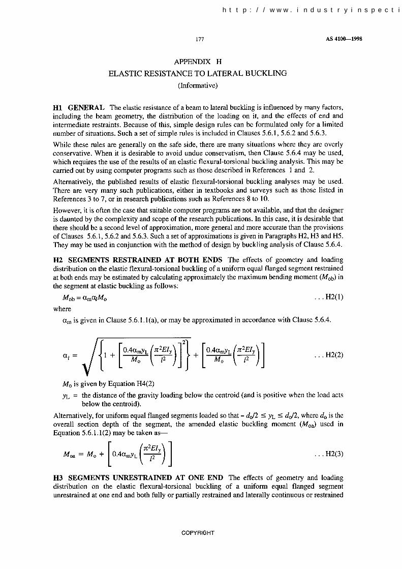
中国工业检验检测网 http://www.industryinspection.com


中国工业检验检测网 http://www.industryinspection.com

AS 4100—1998 180
COPYRIGHT
For segments unrestrained at one end and both fully or partially restrained and laterally continuous orrestrained against lateral rotation at the other end—
�t ��rzl�GJ
25(1 2K2)�(1 K2)
and for segments unrestrained at one end and both fully or partially restrained and unrestrainedagainst lateral rotation at the other end—
�t ��rzl�GJ
5(1 2K2)�(1 K2)
H5.2 End restraints against lateral rotation
H5.2.1 Segments restrained at both ends Continuity of a segment with adjacent segments mayintroduce restraining moments which reduce the lateral rotations and increase the elastic bucklingmoment. The restraint effects depend on the relative minor axis flexural stiffnesses of the adjacentsegments, and these depend in turn on the moment distributions in these segments. The restrainingeffects may be calculated approximately by using the method referred to in References 6 and 9 tocalculate the effective length (le), and by using le instead of the segment length (l) in Equations H4(2)and H4(3).
H5.2.2 Segments unrestrained at one end The approximate elastic buckling moments obtainedby using the values of C3 and C4 of Table H3 in Equations H4(1) to H4(3) are for segments which areprevented from rotating laterally at their restrained ends. For segments which are unrestrainedagainst lateral rotation at their restrained ends, the values of C4 used in Equation H3(2) should bereduced to zero. For a segment with an elastic restraint against lateral rotation at its restrained end, areduced value C4r should be used which may be approximated as follows:
C4r
C4
1.5�ryl�EIy
5 (�ryl�EIy)� 1.0
in which �ry is the elastic stiffness of the flexural end restraint (i.e. the ratio of the restraining minoraxis moment supplied to the end lateral rotation).
H6 REFERENCES
1 BARSOUM, R.S., and GALLAGHER, R.S., Finite element analysis of torsional and torsionalflexural stability problems. International Journal for Numerical Methods in Engineering, Vol. 2,1970, pp. 335-352.
2 HANCOCK, G.J., and TRAHAIR, N.S., Finite element lateral buckling of continuouslyrestrained beam-columns. Civil Engineering Transactions, Institution of Engineers, Australia,Vol. CE20, No. 2, 1978, pp. 120-127.
3 TIMOSHENKO, S.P., and GERE, J.M. Theory of elastic stability. 2nd ed., McGraw-Hill, NewYork, 1961.
4 COLUMN RESEARCH COMMITTEE OF JAPAN. Handbook of structural stability. Corona,Tokyo, 1971.
5 STRUCTURAL STABILITY RESEARCH COUNCIL. Guide to stability design criteria formetal structures. 4th ed., Ed. T.V. Galambos, John Wiley and Sons, New York, 1988.
6 TRAHAIR, N.S., and BRADFORD, M.A. The behaviour and design of steel structures. 2nd ed.,Chapman and Hall, London, 1988.
7 NETHERCOT, D.A. Elastic lateral buckling of beams. Chapter 1 in Developments in thestability and strength of structures. Vol. 2, Beams and beam-columns. Applied SciencePublishers, London, 1983, pp. 1-33.
8 NETHERCOT, D.A., and ROCKEY, K.C. A unified approach to the elastic lateral buckling ofbeams. The Structural Engineer, Vol. 49, No. 7, July 1971, pp. 321-330.
中国工业检验检测网 http://www.industryinspection.com

181 AS 4100—1998
COPYRIGHT
9 NETHERCOT, D.A., and TRAHAIR, N.S. Lateral buckling approximations for elastic beams.The Structural Engineer, Vol. 54, No. 6, June 1976, pp. 197-204.
10 TRAHAIR, N.S. Lateral buckling of overhanging beams. Instability and Plastic Collapse ofSteel Structures. Ed. L.J. Morris, Granada, London, 1983, pp. 503-518.
11 BRIDGE, R.O., and TRAHAIR, N.S. Bending, shear, and torsion of thin-walled beams. SteelConstruction, Australian Institute of Steel Construction, Vol. 15, No. 1, 1981, pp. 2-18.
12 EL DARWISH, I.A., and JOHNSTON, B.G. Torsion of structural shapes. Journal of theStructural Division, ASCE, Vol. 91, No. ST1, 1965, pp. 203-227.
中国工业检验检测网 http://www.industryinspection.com

AS 4100—1998 182
COPYRIGHT
APPENDIX I
STRENGTH OF STIFFENED WEB PANELS UNDER COMBINED ACTIONS
(Informative)
I1 YIELDING CHECK The design bending, shear, axial and bearing actions (or reactions)( M*
w), (V*w), ( N*
w) and ( R*w) on a web panel (see Figure I1) should satisfy the yielding criterion—
� R*w
bbftw�
2
�f*w
� R*
w
bbftw� �f*
w
�
2
� V*w
0.6 Aw�
2
� (fy)2
where
f*w =
N*w
Aw�0.77
M*w
Zwe�
bbf = width of the bearing load on the edge of the web dispersed at 2.5:1 through the flange asshown in Figure 5.13.1(1)
M*w = design bending moment in the web, calculated by elastic theory for sections with
non-compact or slender flanges (see Clause 5.2), or by plastic theory for sections withcompact flanges (see Clause 5.2)
Zwe = elastic section modulus of the web panel
=tw(dp)2
6
FIGURE I1 ACTIONS ON WEB PANEL
中国工业检验检测网 http://www.industryinspection.com

183 AS 4100—1998
COPYRIGHT
I2 BUCKLING CHECK The design bending, shear, axial and bearing actions (or reactions)( M*
w), (V*w), ( N*
w) and ( R*w) on a web panel should satisfy the buckling criterion—
� R*w
Rsb� � N*
w
Nwo� � V*
w
Vv�
2
� M*w
Mw�
2
� 1
where
Nwo = nominal axial load capacity of the web panel if the web panel resisted axial load alone
=45Awfy
�dptw� � fy
250��� Awfy
Vv = nominal shear capacity of the web panel if the web panel resisted shear alone, as specifiedin Clause 5.11
Mw = nominal section moment capacity of the web if the web resisted bending alone, asspecified in Clause 5.2
Rsb = nominal buckling capacity of a transversely stiffened web in bearing alone
= ßwbbftwfy
ßw = 0.10 20
�detw� � fy
250��
de =1.9 (bbfdp)�
�w
�w = �3.4 �2.2dps ���0.4 �0.5bbf
s ��
中国工业检验检测网 http://www.industryinspection.com

AS 4100—1998 184
COPYRIGHT
APPENDIX J
STANDARD TEST FOR EVALUATION OF SLIP FACTOR
(Normative)
J1 TEST SPECIMENS
J1.1 Form The standard test specimen shall be a symmetrical double coverplated butt connectionas shown in Figure J1. The inner plates shall be equal in thickness.
NOTE: It is suggested that the use of M20 bolts will prove to be most convenient, with 25 mm inner platesand 12 mm outer plates.
NOTES:
1 df is the diameter of the bolt.
2 t is the thickness of the plate.
3 Holes in plates:Cover plates 22 mm or df +2 mm. . . . . . . . . . Inner plates 23 mm or df +3 mm. . . . . . . . . .
4 Length and width of inner plates outside of test section may be increased to suit the laboratory’s testingfacilities.
5 Dimensions are shown for the use of M20 bolts. Dimesnions in parentheses are for use of bolts withnominal diameter df mm, which should not be less than 16 mm.
DIMENSIONS IN MILLIMETRES
FIGURE J1 STANDARD TEST SPECIMEN
中国工业检验检测网 http://www.industryinspection.com

中国工业检验检测网 http://www.industryinspection.com

AS 4100—1998 186
COPYRIGHT
J3 METHOD OF TESTING The method of testing shall satisfy the following requirements:
(a) Type of loading Specimens shall be tested only by tensile loading.
(b) Loading rate Up to the slip load, force shall be applied in increments exceeding neither 25 kNnor 0.25 times of the slip load of the connection assuming a slip factor of 0.35 and thecalculated bolt tension. The loading rate shall be approximately uniform at not more than50 kN/min within each load increment. Slower loading rates are preferred. Each loadincrement shall be applied after creep at constant load due to the preceding load increment haseffectively ceased.
NOTES:
1 Since slip will in all probability occur at one bolt position before the other, it is clear that the first bolt mayslip into bearing before the slip load at the other bolt position is attained.
2 After attainment of the slip load at one bolt position, the loading rate and increment size may be adjustedat the discretion of the operator.
J4 SLIP LOAD Slip is usually well defined and easily detected when a sudden increase indeformation occurs. One or more sharp clearly audible reports may also be heard. However, withsome types of surface, and occasionally with normal surfaces, the incidence of slip is not so welldefined. In these cases, the load corresponding to a slip of 0.13 mm shall be used to define the slipload.
FIGURE J2 TYPICALLY INSTRUMENTED TEST ASSEMBLY
中国工业检验检测网 http://www.industryinspection.com
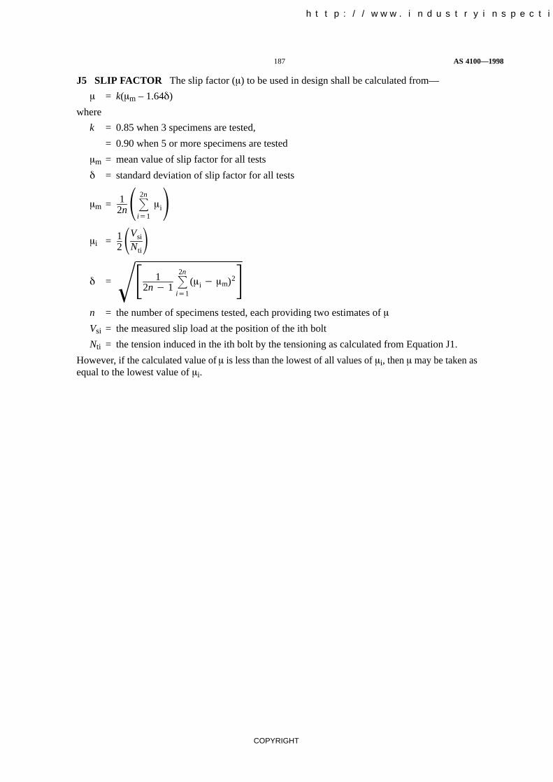
187 AS 4100—1998
COPYRIGHT
J5 SLIP FACTOR The slip factor (�) to be used in design shall be calculated from—
� = k(�m – 1.64�)
where
k = 0.85 when 3 specimens are tested,
= 0.90 when 5 or more specimens are tested
�m = mean value of slip factor for all tests
� = standard deviation of slip factor for all tests
�m = 12n��2n
i1
�i��i = 1
2�Vsi
Nti�
� = � 12n � 1
�2n
i1
(�i � �m)2��n = the number of specimens tested, each providing two estimates of �
Vsi = the measured slip load at the position of the ith bolt
Nti = the tension induced in the ith bolt by the tensioning as calculated from Equation J1.
However, if the calculated value of � is less than the lowest of all values of �i, then � may be taken asequal to the lowest value of �i.
中国工业检验检测网 http://www.industryinspection.com

AS 4100—1998 188
COPYRIGHT
APPENDIX K
INSPECTION OF BOLT TENSION USING A TORQUE WRENCH
(Informative)
K1 GENERAL The correlation between the torque required to fully tension a calibrationspecimen and that which will be required on a bolt-nut assembly installed in a structural connection,will be materially affected by such factors as—
(a) the actual condition of the thread and the bearing face surface and their lubrication;
(b) the occurrence of galling during tensioning; and
(c) the time lapse between tensioning and inspection.
With due regard for these limitations, the procedure given in this Appendix is considered the mostpractical method for an independent assessment of whether gross undertensioning exists.
K2 CALIBRATION The inspection wrench may be either a hand-operated or anadjustable-torque power-operated wrench. It should be calibrated at least once per shift, or morefrequently if the need to closely simulate the condition of the bolts in the structure so demands.
The torque value determined during calibration may not be transferred to another wrench.
At least three bolts, desirably of the same size (the minimum length may have to be selected to suit thecalibrating device) and condition as those under inspection, should be placed individually in acalibrating device capable of indicating bolt tension. A hardened washer should be placed under thepart turned.
Each calibration specimen should be tensioned in the calibrating device by any convenient means to1.05 times the minimum bolt tension specified for that diameter in Table 15.2.5.1. The inspectionwrench then should be applied to the tensioned bolt, and the torque necessary to turn the nut or bolthead 5° (approximately 25 mm at 300 mm radius) in the tensioning direction should be determined.The average torque measured in the tests of at least three bolts should be taken as the job inspectiontorque.
K3 INSPECTION Bolts represented by the sample which have been tensioned in the structureshould be inspected by applying, in the tensioning direction, the inspection wrench with its jobinspection torque to such proportion of the bolts in the structure as prescribed.
NOTE: For guidance, it is suggested that a suitable sample size would be 10% of the bolts, but not less thantwo bolts in each connection.
K4 ACTION Where no further rotation occurs under the torque applied by the inspection wrench,the connection should be accepted as properly tensioned.
Where any nut or bolt head is turned by the application of the job-inspection torque, this torqueshould then be applied to all other bolts in the connection and all bolts whose nut or head is turned bythe job inspection torque should be tensioned and re-inspected. Alternatively, the Fabricator orErector may retension all of the bolts in the connection and then resubmit the connection forinspection.
中国工业检验检测网 http://www.industryinspection.com

189 AS 4100—1998
COPYRIGHT
INDEX
Acceptance 2.2.2, 17.4.3, 17.5.3, 17.5.4
Action 1.3combined 5.1, 5.7, 5.12, 8, 9.3.2.3, 9.3.3.3, 9.4.3, 9,8.3,
Appendix Idesign 1.3, 8.2, 9.1.4, 9.4, 9.8nominal 1.3other 3.2.2
Action effect 1.3, 3.2, 4, 4.1design 1.3, 3.3, 3.4, 4
Alignment 15.2.3
Amplification 3.5.2, 4.4.2.2, 4.4.2.3, 4.5.4, Appendices E, F
Analysisadvanced 4.1.1, 8.2, Appendix Dassumptions for 4.3, 4.4.1.1, 4.5.3bolt group 9.4.1, 9.4.2, 9.4.3elastic 4.1.1, 4.4, 5.1, 8.2, 8.4.2elastic first-order 4.4.2, 8.2elastic second-order 4.4.1, 8.2, Appendix Eflexural-torsional buckling 5.6.4member buckling 4.6plastic 4.1.1, 4.5, 5.1, 5.10.6, 8.2, 8.4.3, 9.1.2.4, 13.3.4.3,
13.3.4.4plastic first-order 8.2plastic second-order 8.2weld group 9.8.1, 9.8.2, 9.8.3
Angle 5.3.2.4, 5.6.1.3lacing 6.4.2.3single 8.4.6
Areaeffective 6.2.2, 9.7.2.5, 9.7.3.6gross 6.2.2, 7.2minimum 5.15.3net 7.2
Assembly 15.2.3, 15.2.4
Authority 1.3
Batten 6.4.3, 7.4.5
Beam 3.5.4, 4.3.1, 4.6.3.4, 4.7.2.1, 4.7.2.2, 5, 12.6.1, 14.4.5,15.3.5, 15.5.1, B1
Bearing capacity 5.13.2, Appendix Ibuckling 5.13.4, 5.14.2pin 9.5.2ply 9.3.2.4, 9.5.4yield 5.13.3, 5.14.1
Bending 5, Appendices H, Ibiaxial 5.7, 8.3.4, 8.4.5compression and 8non-principal plane 5.7shear and 5.12tension and 8uniaxial 8.3.2, 8.3.3, 8.4.2, 8.4.3, 8.4.4
Bolt 2.3.1, 9.3, 9.6, 14.3.6.1anchor 2.3.6, 15.3.1galvanized 15.2.4.4grade of 9.3.1tensioned 14.3.6.2, 15.2.4, 15.4.1
中国工业检验检测网 http://www.industryinspection.com

AS 4100—1998 190
COPYRIGHT
Bolt group 9.4
Bolt serviceability 3.5.5, 9.1.6, 9.3.3
Bolting 14.3.6, 15.2.3, 15.2.4, 15.2.5category of 9.3.1
Braced member 1.3, 4.1.2, 4.4.2.2, 4.6.3.3, 4.7.2.1, Appendix G
Bracing 5.4.3, 6.6, 15.2.1
Brittle fracture 3.7, 10
Bucklingframe 4.7lateral 5.6, Appendix Hmember 4.6, Appendix G
Buckling coefficient 6.2.4
Buckling load 4.6.1, 4.6.2, Appendix G
Buckling moment, reference 5.6.1.1, H4
Buckling references, lateral H6
Building 4.3.3multi-storey 3.2.4, 4.3.1regular 4.3.1
Capacitybiaxial bending 8.3.4, 8.4.5design 1.3, 3.3, 3.4in-plane 8.4.2, 8.4.3member 5.3, 5.6, 6.3, 8.4nominal 1.3out-of-plane 8.4.4plastic moment 8.4.3.4section 5.2, 6.2, 7.2, 8.3weld 9.7.2.7, 9.7.3.10, 9.7.5.3, 9.8.4
Capacity factor 1.3, Table 3.4, 3.5.5, 11.8.1
Castellated member 5.10.7
Casting, steel 2.4
Centre of rotation 9.4.1, 9.8.1.1
Cleaning 16.3
Column 4.3.1, 4.3.4, 4.4.2.3, 4.7.2.1, 4.7.2.2, 12.6.1, 15.3.2,15.3.4
Combined actions 5.1, 5.7, 8, 9.3.2.3, 9.3.3.3, 9.4.3, 9.8.3, Appendix I
Compression capacity 6, Appendix Imember 6.3.3, 6.3.4section 6.2.1
Compression member 6, 8.4.2.2, 8.4.4.1, 8.4.5.1, 14.4.4, 15.3.3, 15.5.1back-to-back and separated 6.5.1back-to-back in contact 6.5.2battened 6.4.3laced 6.4.2single angle 8.4.6
Compression member section constant Tables 6.3.3(1) and (2)
Configuration 6.5.1.2, 6.5.2.2
Connection 9, 7.4.2, 12.10.1, 13.3.1, 13.3.4.3, 13.3.4.5, 14.3.6.3,15.2.1
bearing-type 1.3, 9.2, 14.3.6.3combined 9.1.7component of 9.1.9compression member 6.5.1.4design of 4.2.5, 9, 9.1.3
中国工业检验检测网 http://www.industryinspection.com

191 AS 4100—1998
COPYRIGHT
eccentric 7.3.2friction-type 1.3, 9.2, 9.3.3, 14.3.5.2, 14.3.6.3full strength 4.5.3hollow section 9.1.11inspection of bolted 15.4partial strength 4.5.3pin 7.5, 9.5, 14.3.7restraining member 5.4.1, 6.6.2splice 9.1.4, 14.3.2, 14.4.4.2, 15.3.4
Construction 1.5.1, 1.7, 14, 15rigid 4.2.2, 9.1.2.1semi-rigid 4.2.3, 9.1.2.2simple 4.2.4, 4.3.4, 9.1.2.3
Contact surface 9.3.3.2, 14.3.6.3, 16.3, C4
Corrosion 11.1.1
Corrosion cracking, stress 11.1.1
Corrosion protection 1.6.1, 3.5.6, 15.2.2, Appendix C
Critical flange 5.4.2, 5.4.3, 5.5
Critical section 5.3.1, 5.3.3
Cropping 14.3.3
Cutting 14.3.3, 14.3.5.1, 16.4.1
Damage 15.4.2
Defect, surface 14.2.1
Deflection 3.5.2constrained 5.7.1unconstrained 5.7.2
Deflection limit 3.5.3, Appendix B
Deformation, test 17.3
Delivery 15.2.2
Design 3.1aim of 3.1.1data for 1.6.1details of 1.6.2other requirement of 3.11requirement of 3.1.2
Detail category 1.3, 11.1.2, 11.5, Tables 11.5.1(1) to (4)normal stress 11.5.1shear stress 11.5.2
Diaphragm 5.8
Dispersion of bearing force 5.13.1, 5.13.4
Discontinuity 1.3, 11.1.2
Drift 13.2, 13.3.1
Ductility (earthquake) 1.3, 13.2, 13.3.1, 13.3.4.3, 13.4
Earthquake 3.10, 13
Eccentricity 4.3.4, 5.15.7.1, 7.3.2, 8.4.6, 9.1.5
Edge distancemaximum 9.6.4minimum 9.6.2
Effective lengthbending member 5.6.3, H5.2.1compression member 4.6.3, 6.3.2, 6.4.2.4, 6.4.3.3, 8.4.2.2, 13.8.2,
Appendix Gweld 9.7.2.4, 9.7.3.5
Elastic modulus 4.6.2, 5.6.1, 12.4.2, Appendix G, H4
中国工业检验检测网 http://www.industryinspection.com

AS 4100—1998 192
COPYRIGHT
Equipment support 15.1.3
Erection 15
Erection procedure 15.2
Erection safety 15.1.2
Exemption from fatigue assessment 11.4, 11.7
Existing structure 1.5.2
Exposed surface area to mass ratio 1.3, 12.2, 12.6, 12.7, 12.8
Exterior element 13.5.6
Fabrication 13.9, 14
Fastener 2.3choice of 9.1.6equivalent high-strength 2.3.2explosive 2.3.5non-slip 1.3, 4.5.2, 9.1.7, 9.2
Fatigue 1.3, 3.8, 4.5.2, 11, 11.1.2assessment of 11.9high stress-low cycle 11.1.1thermal 11.1.1
Fatigue limitconstant stress range 1.3, 11.1.2, Figures 11.6.1, 11.6.2cut-off 1.3, 11.1.2, Figures 11.6.1, 11.6.2
Fatigue loading 1.3, 11.1.2, 11.2
Fatigue strength 1.3, 11.1.2, 11.6normal stress 11.6.1shear stress 11.6.2
Filler plate 9.3.2.5
Fire 3.9, 12
Fire exposure condition 1.3, 12.2, 12.6.1, 12.6.2.2, 12.6.3, 12.7, 12.8, 12.9
Fire protection system 1.3, 12.2, 12.6.2.2, 12.6.3, 12.8
Fire-resistance level 1.3, 1.6.1, 12.1, 12.2
Fire test, standard 1.3, 12.2, 12.6.3
Fitting load-bearing stiffener 5.14.4
Forcedesign 5.15.7, 6.4.1, 6.4.3.7, 6.5.1.5, 6.5.2.5, 7.4.2earthquake 3.2.1, 13.1external 5.15.7notional horizontal 3.2.4, 6.6.1prying 1.3, 9.1.8, 9.2
Force distributionnon-uniform 7.3.2uniform 7.3.1
Form factor 6.2.2, 6.3.3, 8.3.2, 8.3.3, 8.3.4, 8.4.2.2, 8.4.3.1, 8.4.4.1
Form of construction 4.2.1rigid 4.2.2, 9.2.1semi-rigid 4.2.3, 9.1.2.2simple 4.2.4, 4.3.4, 9.1.2.3
Frame 4.3.1, 4.7.2.1, 4.7.2.2, 8.2, 8.4.1, 8.4.3.1, Appendices D, E, F, G
braced 1.3, 13.2ductile momentresisting space 1.3, 13.2moment resisting space 1.3, 13.2non-rectangular 4.4.2.3rectangular 4.4.2.3, 4.6.3.4, 4.7.2.1, 4.7.2.2space 1.3, 13.2
中国工业检验检测网 http://www.industryinspection.com

193 AS 4100—1998
COPYRIGHT
Grouting 15.5
Handling 15.2.2, C5
Heat treatment 10.4.3.3
Hole 5.2.6, 6.2.1, 7.2, 9.1.10, 9.6.5, 11.9, 13.9.2, 14.3.5oversize 14.3.5.2round 14.3.5.2size of 14.3.5.2slotted 14.3.5.2
Holing 14.3.5
Hollow section 9.1.11, 11.3.1circular 5.2.2, 5.2.5, Table 5.2, 5.11.3, 5.13.5, 6.2.3, 6.2.4rectangular 5.3.2.4, 5.6.1.4, 5.13.5square 5.13.5
Identification 14.2.2
Inaccessible surface C4
Inspectionbolt tension Appendix Kbolt connection 15.4
Intersection 9.1.5
Lacing angle 6.4.2.3
Lacing, mutually opposed 6.4.2.6
Length (of a compression member) 1.3, 6.3.1
Life, design 1.3, 11.1.2
Limit state 1.3serviceability 1.3, 3.5, 3.6, 9.3.3, 17.4.3, 17.5.3, Appendix Bstability 1.3, 3.3strength 1.3, 3.4, 3.6, 5, 6, 7, 8, 9, 9.7.3.10, 9.7.5.3, 17.4.3, 17.5.3
Limitation 4.5.2, 9.7.4.3, 10.4.2, 11.1.4, 11.10, 12.6.2.2, 14.3.5.2
Load 1.3, 3.2.1arrangement of live 4.3.3batten 6.4.3.7combination of 3.2.3, 3.5.2design 1.3, 3.2.3in-plane 1.3, 9.2, 9.4.1, 9.4.3, 9.8.1, 9.8.3nominal 1.3, 1.6.1, 3.2.1out-of-plane 1.3, 9.2, 9.4.2, 9.4.3, 9.8.2, 9.8.3test 17.4.2, 17.5.2
Load effect 1.3, 3.2, 4, 4.1design 1.3, 3.3, 3.4, 4.1
Load height 5.6.3, H2, H3
Loading event, nominal 1.3, 11.1.2, 11.3.2
LODMAT 10.3.1, Figure 10.3
Machining 14.3.2
Material 1.5.1, 2, 14.2, 16.2alternative 1.5selection of 10.4
Member 4, 5, 6, 7, 8braced 1.3, 4.1.2, 4.4.2.2, 4.6.3.3, 4.7.2.1, Appendix Gcastellated 5.10.7compression 4.4.2, 4.6, 4.7, 6, Appendices F, Gconstant cross-section 5.6.1.1(a), 6.3.3parallel restrained 5.4.3.3, 6.6.3sway 1.3, 4.1.2, 4.4.2.3, 4.6.3.3, 4.7.2.2, Appendix Ftension 4.4.2, 7varying cross-section 5.6.1.1(b), 6.3.4

AS 4100—1998 194
COPYRIGHT
Methodaction effect determination 4.1alternative 1.5analysis—see under analysisbrittle fracture design 10.1direct-tension indication 15.2.5.3fabrication 14.3.1fire design 12.1fatigue assessment 11.8fracture assessment 10.5interaction 5.12.3limiting temperature time 12.6.1notch-ductile range 10.2part-turn 15.2.5.2proportioning 5.12.2slip factor testing J3stress cycle counting 1.3, 11.1.2tensioning 15.2.5
Miner’s summation 1.3, 11.1.2, 11.8.2
Modification 16
Moment amplification 4.4.2.2, 4.4.2.3, Appendices E, F
Moment capacitymember 5.3, 5.6pin 9.5.3plastic 8.4.3.4section 5.2
Moment modification factor 5.6.1.1, Table 5.6.1, 5.6.2, Table 5.6.2, 5.6.4
Notation 1.4, 11.1.3
Nut 2.3.1, 14.3.6.1, 15.2.4.1
Nut rotation Table 15.2.5.2
Outstandplate 5.2.2, Table 5.2, 6.2.3, 6.2.4, Table 6.2.4stiffener 5.14.3, 5.15.6
Packing 1.1, 9.9, 15.2.4.2
Period of structural adequacy (fire) 1.3, 12.2, 12.3, 12.8
Pin 1.3, 7.5, 9.2, 9.5, 9.6
Pitchmaximum 9.6.3minimum 9.6.1
Plastic hinge 1.3, 4.5.3, 13.3.4.3
Platebatten 6.4.3, 7.4.5filler 9.3.2.5side-reinforcing 5.10.3tie 6.4.2.7, 7.4.4
Ply 9.3.2.4, 9.5.4
Post, end 5.15.2.2, 5.15.9
Prototype(fire) 1.3, 12.2, 12.6.2.2, 12.6.3, 12.8
Punching 11.9, 13.3.4.5, 14.3.5.1
Reference, lateral buckling H6
Reference document Appendix A
Rejection 14.1, 15.1.1
Repair 16, C6
Resistance effect, design 1.3, 3.3
Restrained cross-section 5.4.1
中国工业检验检测网 http://www.industryinspection.com

195 AS 4100—1998
COPYRIGHT
fully 5.4.2.1full lateral 5.3, 5.3.2laterally 5.4.2.4partially 5.4.2.2rotationally 5.4.2.3
Restrained member, parallel 5.4.3.3, 6.6.3
Restraintcompression member 6.6.2continuous lateral 5.3.2.2end 4.6.3.1, 4.6.3.2, 4.6.3.3full 5.3.2.4full lateral 5.3, 5.3.2idealised end 4.6.3.2intermediate lateral 5.3.2.3lateral deflection 5.4.3.1lateral rotation 5.4.3.4, 5.6.3, H5.2partial 5.3.2.4torsional end 5.14.5twist rotation 5.4.3.2, 5.6.3, H5.1
Restraint system 6.6.1
Roughness, surface 14.3.3, Table 14.3.3
S-N curve 1.3, 11.1.2, Figures 11.6.1, 11.6.2
Sawing 14.3.2, 14.3.3
Scope 1.1
Second-order effect 4.4.1.2, 4.5.4, 8.2, Appendix E
Sectionangle 5.3.2.4, 5.6.1.3, 8.4.6circular hollow 5.2.2, 5.2.5, Table 5.2, 5.11.3, 6.2.3, 6.2.4compact 4.5.2, 5.2.3, 8.3.2, 8.3.3, 8.3.4, 8.4.2.2, 8.4.3.1, 8.4.4.1critical 5.3.1, 5.3.3hollow 9.1.11, 11.3.1non-compact 5.2.4open 11.3.1open equal flange 5.3.2.4, 5.6.1.1rectangular hollow 5.3.2.4, 5.6.1.4slender 5.2.5unequal flange I 5.3.2.4, 5.6.1.2unrestrained 5.4.1
Section modulus 5.2.3, 5.2.4, 5.2.5, 5.2.6
Segment 1.3, 5.3, 5.3.1constant cross-section 5.6.1.1(a)sub- 5.3.2.3, 5.6.1.1(a), 5.6.3varying cross-section 5.6.1.1(b)
Segment(in a member subjected to bending) 1.3, 5.3.1
Segment with both ends restrained 5.3.2.4, 5.5.2, 5.6.1, H2, H5.1, H5.2.1
Segment with full lateral restraint 5.3
Segment with one end unrestrained 5.5.3, 5.6.2, H3, H5.1, H5.2.2
Segment without full lateral restraint 5.6
Separator 5.8
Shear and bending interaction 5.1, 5.12
Shear capacitybolt 9.3.2.1, 9.3.3.1pin 9.5.1web 5.11, Appendix Iweb buckling 5.11.5web yield 5.11.4
中国工业检验检测网 http://www.industryinspection.com

AS 4100—1998 196
COPYRIGHT
Shear stress distributionapproximately uniform 5.11.2non-uniform 5.11.3
Shear wall 1.3
Sheared edge 13.3.4.5
Shearing 14.3.3
Slendernessbatten 6.4.3.4compression member 6.3.1, 6.3.3, 6.3.4, Table 6.3.3(3), 6.4.2.2, 6.4.3.2,
6.5.1.3, 6.5.2.3lacing 6.4.2.5main component 6.4.2.1, 6.4.3.1member 5.6.1.1, 8.4.2plate element 5.2.2, 6.2.3section 5.2.2web 8.4.3.3
Slenderness limit Table 5.2, Table 6.2.4, 6.4.2.5, 6.4.3.4
Slenderness ratio 6.4.2.2, 6.4.3.1, 6.4.3.2geometrical 1.3, 6.3.1
Slenderness reduction factor 5.6.1, 6.3.3, Table 6.3.3(3)
Slip 3.5.1, 3.5.5, 9.3.3, Appendix J
Slip factor 9.3.3.1, 9.3.3.2, Appendix J, J5
Span 4.3.2
Spectrumdesign 1.3, 11.1.2, 11.3stress 1.3, 11.1.2, 11.3
Standard 2.2.1, 2.3.1, 3.2.1, Appendix A, C7
Steelacceptance of 2.2.2grade of 1.6.1, Table 2.1, 10.4.4, Table 10.4.4strength Table 2.1type of 10.4.1, Table 10.4.4unidentified 2.2.3, 14.2.2
Stickability 1.3, 12.2, 12.6.2.2, 12.6.3
Stiffenerbuckling capacity 5.14.2, 5.15.4connection to web of 5.15.8intermediate transverse 5.10.4, 5.10.5, 5.15load-bearing 5.10.2, 5.14, 13.3.4.2, 13.3.4.3longitudinal 5.10.5, 5.16spacing 5.15.2
Stiffnesshigh 13.3.1increase in 5.15.7.1minimum 5.15.5, 5.16.2
Stiffness ratio 4.6.3.3, 4.6.3.4, Appendix G
Storage 15.2.2
Strain 10.4.3.1, 10.4.3.2
Strength, increase in 5.15.7.2
Strengthening 16
Stress, design 11.3.1
Stress concentration 11.1.2, 11.3.1
Stress cycle 1.3, 11.1.2, 11.6.1, 11.6.2, 11.8.1, 11.8.2
Stress cycle counting method 1.3, 11.1.2, 11.3.2
中国工业检验检测网 http://www.industryinspection.com

197 AS 4100—1998
COPYRIGHT
Stress range 1.3, 11.1.2constant 11.8.1variable 11.8.2
Structural adequacy (fire) 1.3, 12.1, 12.2, 12.3
Stud, welded 2.3.4, Table 11.5.1(2), 14.3.4
Surface, contact 9.3.3.2, 14.3.6.3, 16.3, C4
Sway member 1.3, 4.1.2, 4.4.2.3, 4.6.3.3, 4.7.2.2, Appendix F
Systemrestraint 6.6.1
Temperature 12.4basic design 10.3.1design service 10.3.1, 10.3.2permissible service 10.4.1, Table 10.4.1limiting steel 12.5, 12.6.1reference 15.1.4variation of 12.6.2, 12.6.3
Tensile strength 1.3, Table 2.1, 4.5.2, Table 9.3.1, Table 9.7.3.10(1)used in design 2.1.2, 2.2.3
Tension 7bolt 9.3.2.2, 9.3.2.3, 9.3.3.3, 15.2.5, Appendix Kminimum bolt 9.3.3.1, 15.2.5.1, Table 15.2.5.1
Tension capacity 7, 13.3.4.2bolt 9.3.2.2, 9,3.3.3section 7.2
Tension member 7, 8.4.2.3, 8.4.4.2, 8.4.5.2, 14.4.6, 15.3.6back-to-back 7.4.3battened 7.4.5laced 7.4.4
Tensioningfull 1.3, 9.2, 15.2.4.3, 15.2.5, Appendix Kre- 15.2.4.4snug-tight 1.3, 9.2, 15.2.4.3,15.2.5.2
Testing 17load 3.6, 17proof 1.3, 17.2, 17.4prototype 1.3, 17.2, 17.5report of 17.6slip factor Appendix J
Thicknessbatten 6.4.3.6design throat 9.7.2.3, 9.7.3.4, 9.7.5.2fatigue strength effect of 11.8web 5.9.3, 5.10.1, 5.10.4, 5.10.5, 5.10.6
Tie plate 6.4.2.7, 7.4.4
Time 12.6, 12.7
Tolerance 14.4, 15.3anchor bolt location 15.3.1beam 14.4.5, 15.3.5beam level and alignment 15.3.5column base 15.3.2column splice 15.3.4compression member 14.4.4cross-section 14.4.3full contact 14.4.4.2, 15.3.2.3length 14.4.4.3, 14.4.5.2, 14.4.6.2overall building dimension 15.3.7plumbing 15.3.3rotation 15.2.5.2
中国工业检验检测网 http://www.industryinspection.com

AS 4100—1998 198
COPYRIGHT
straightness 14.4.4.1, 14.4.5.1. 14.4.6.1tension member position 15.3.6
Transition 9.7.2.6
Triangulated structure 4.1.2, 4.3.4, 4.6.3.5
Truss 4.1.2, 8.4.6, 11.3.1
Unidentified steel 2.2.3, 14.2.2
Unrestrained cross-section 5.4.1
Vibration 3.5.4
Washer 2.3.1, 14.3.6.1
Webarrangement of 5.10design of 5.9longitudinally stiffened 5.10.5opening in 5.10.7, 12.10.2thickness of 5.9.3, 5.10.1, 5.10.4, 5.10.5, 5.10.6transversely stiffened 5.10.4, 5.10.5, 5.11.5.2, Appendix Iunstiffened 5.10.1, 5.11.5.1
Web panel 5.9.2, Appendix Iinterior 5.15.2.1end 5.15.2.2
Weld 2.3.3, 9.1.6, 9.1.7, 9.7area of 9.7.2.5, 9.7.3.6, 9.7.4.2butt 9.7.2, 13.3.4.2, 13.3.4.3category of 9.7.1.3, 11.1.5, 13.3.4.2, 13.3.4.3complete penetration butt 1.3, 9.7.2compound 9.7.5fillet 9.7.3GP 9.7.1.3incomplete penetration butt 1.3, 9.7.2length of 9.7.2.4, 9.7.3.5, 9.7.3.9, 9.7.4.1plug and slot 9.7.4prequalified preparation of 1.3quality of 9.7.1.3SP 9.7.1.3, 11.1.5, 13.3.4.2, 13.3.4.3spacing of 9.7.3.7, 9.7.3.8size of 9.7.2.2, 9.7.3.1, 9.7.3.2, 9.7.3.3type of 9.7.1.2
Weld group 9.8
Welding 14.3.4, 16.4
Widthbatten 6.4.3.5effective 5.2.5, 6.2.4
Yield stress 1.3, Table 2.1, 4.5.2, 12.4.1, 13.3.2, 13.3.3, 13.3.4.1,13.3.4.3
used in design 1.1, 2.1.1, 2.2.3
中国工业检验检测网 http://www.industryinspection.com