ashly power amplifier this document is for use with ashly ampli ers and asti equipment only. please...
TRANSCRIPT

Ashly Power Amplifier

Contents
Contents 1
1 Introduction 21.1 Dimensions . . . . . . . . . . . . . . . . . . . . . . . . . . . . . . . . . . . . . . . . . 2
2 Getting Started 32.1 Proper Cooling . . . . . . . . . . . . . . . . . . . . . . . . . . . . . . . . . . . . . . . 32.2 Setup Procedure . . . . . . . . . . . . . . . . . . . . . . . . . . . . . . . . . . . . . . 32.3 Powering Up the Amplifier . . . . . . . . . . . . . . . . . . . . . . . . . . . . . . . . 4
3 General Information 53.1 Front Indication Lights . . . . . . . . . . . . . . . . . . . . . . . . . . . . . . . . . . . 53.2 Rear Panel Connections . . . . . . . . . . . . . . . . . . . . . . . . . . . . . . . . . . 53.3 Front Panel Connections . . . . . . . . . . . . . . . . . . . . . . . . . . . . . . . . . . 6
4 Technical Specifications 64.1 Wiring . . . . . . . . . . . . . . . . . . . . . . . . . . . . . . . . . . . . . . . . . . . . 64.2 Minimum Guaranteed Power . . . . . . . . . . . . . . . . . . . . . . . . . . . . . . . 64.3 Memory Devices . . . . . . . . . . . . . . . . . . . . . . . . . . . . . . . . . . . . . . 64.4 Reliability . . . . . . . . . . . . . . . . . . . . . . . . . . . . . . . . . . . . . . . . . . 7
5 References 75.1 Ashly Amplifier Part Numbers . . . . . . . . . . . . . . . . . . . . . . . . . . . . . . 7
1
Note: This document is for use with Ashly Amplifiers and ASTi equipment only. Please refer toAshly’s website1 for more information.
1 Introduction
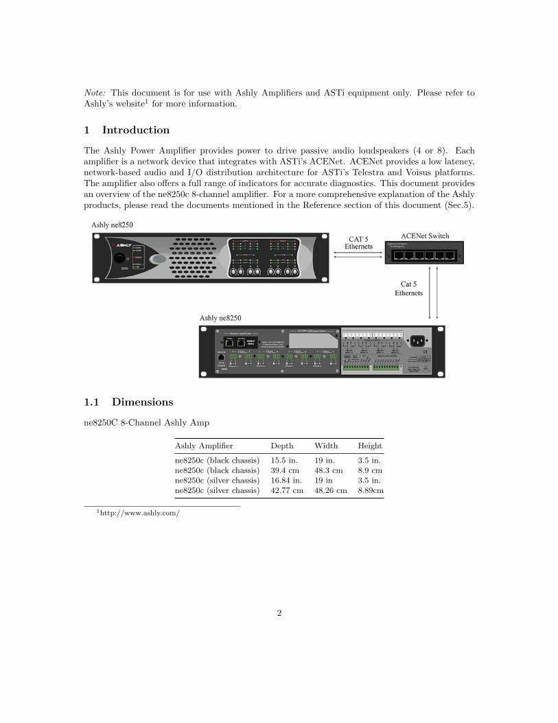
The Ashly Power Amplifier provides power to drive passive audio loudspeakers (4 or 8). Eachamplifier is a network device that integrates with ASTi’s ACENet. ACENet provides a low latency,network-based audio and I/O distribution architecture for ASTi’s Telestra and Voisus platforms.The amplifier also offers a full range of indicators for accurate diagnostics. This document providesan overview of the ne8250c 8-channel amplifier. For a more comprehensive explanation of the Ashlyproducts, please read the documents mentioned in the Reference section of this document (Sec.5).
1.1 Dimensions
ne8250C 8-Channel Ashly Amp
Ashly Amplifier Depth Width Height
ne8250c (black chassis) 15.5 in. 19 in. 3.5 in.ne8250c (black chassis) 39.4 cm 48.3 cm 8.9 cmne8250c (silver chassis) 16.84 in. 19 in 3.5 in.ne8250c (silver chassis) 42.77 cm 48.26 cm 8.89cm
1http://www.ashly.com/
2

2 Getting Started
Warning: Before amplifier installation, ensure that your amplifier is not connected to powerand all control levels are turned down (counterclockwise).
2.1 Proper Cooling
Do not block any of the amplifier ventilation vents. When using an equipment rack, mount theunits directly on top of each other. Do not block rear, front, or side air vents. The side walls of therack should be a minimum of one inch (2.5cm) away from the amplifier sides, and the back of therack should be open.
2.2 Setup Procedure
1. Use the “Primary” or “Secondary” port and a Cat 5 cable to connect to the ACENet switch.Do not connect both.
2. Connect the “10/100 Ethernet” port to the ACENet switch.
3. Connect the AC power cord.
The Analog Input Connectors are not used in the ASTi system setup.
Warning: Do not connect or disconnect speakers or ACENet while the amplifier is poweredon.
3
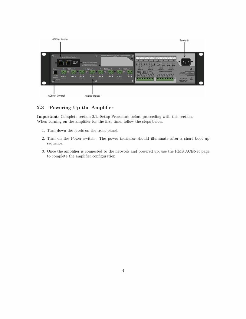
2.3 Powering Up the Amplifier
Important: Complete section 2.1. Setup Procedure before proceeding with this section.When turning on the amplifier for the first time, follow the steps below.
1. Turn down the levels on the front panel.
2. Turn on the Power switch. The power indicator should illuminate after a short boot upsequence.
3. Once the amplifier is connected to the network and powered up, use the RMS ACENet pageto complete the amplifier configuration.
4
Remember : Disconnect the power cord before making any change to the installation or wiring.
3 General Information
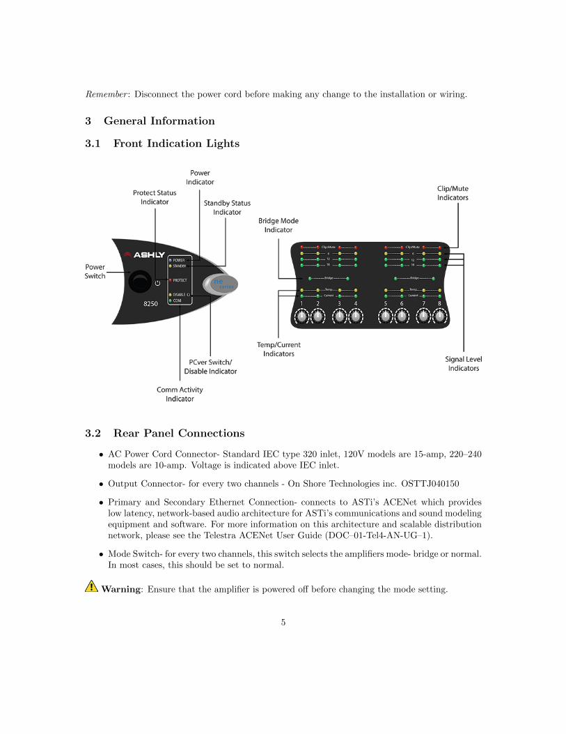
3.1 Front Indication Lights
3.2 Rear Panel Connections
• AC Power Cord Connector- Standard IEC type 320 inlet, 120V models are 15-amp, 220–240models are 10-amp. Voltage is indicated above IEC inlet.
• Output Connector- for every two channels - On Shore Technologies inc. OSTTJ040150
• Primary and Secondary Ethernet Connection- connects to ASTi’s ACENet which provideslow latency, network-based audio architecture for ASTi’s communications and sound modelingequipment and software. For more information on this architecture and scalable distributionnetwork, please see the Telestra ACENet User Guide (DOC–01-Tel4-AN-UG–1).
• Mode Switch- for every two channels, this switch selects the amplifiers mode- bridge or normal.In most cases, this should be set to normal.
Warning: Ensure that the amplifier is powered off before changing the mode setting.
5

• Input Connectors- removable euroblock connectors for balanced analog audio signal input.The Input Connectors are not used in the ASTi system setup.
3.3 Front Panel Connections
• Channel Level Controls- act as the overall master gain control for each channel. The exact set-ting required for any specific installation will depend on a number of factors including speakerplacement, speaker sensitivity, size of the space being driven, and of course the required soundlevel required from the system. Conventional audio set-up procedures apply, such that thesignal source should be set to the maximum level achievable while avoiding overload (clipping)for the loudest signal levels required from the system (typically the “crash” sound for a flightsimulator), this affording the maximum signal-to-noise performance, and then setting the am-plifier Channel Level Controls to achieve the required loudness for this particular sound. Innormal use, the Telestra configuration service will disable these controls.
4 Technical Specifications
4.1 Wiring
Select the appropriate size of the wire based on the distance from the amplifier to the speaker.
Distance Wire Size
up to 25 ft. (7.6 m) 16 AWG26–40 ft. (7.9–12.2 m) 14 AWG41–60 ft. (12.5–18.3 m) 12 AWGOver 60 ft. (18.3 m) 10 AWG
Warning: Never connect the speaker return to the chassis of the amplifier or damage to theamplifier may result. Never use shielded cable for output wiring.
4.2 Minimum Guaranteed Power
- 150W per channel @ 8 Ohms
- 250W per channel @ 4 Ohms
4.3 Memory Devices
The Ashly Amp memory devices are summarized in the table below.
Volatile
MCU Internal Flash 512kbMCU Internal SRAM 64kb
6
Non-Volatile
SRAM 32kbFlash 2 Mb
4.4 Reliability
Typical System Mean Time Between Failure (MTBF)
ne8250 low-Z 478,000 hours
5 References
For more information and Ashly-specific documentation, visit the Ashly Technical Support2 page.Training videos are also available on Ashly’s Youtube3 page.
5.1 Ashly Amplifier Part Numbers
This document refers to a specific Ashly amplifier. If purchasing an Ashly amplifier from anothersource, follow the part numbers below to ensure compatibility. Similar part numbers that mayappear to be the same will not work consistently with ASTi’s ACENet architecture.
Ashly Amplifier Part Number
ne8250 with CNM–2 expansion card A-PAMP-ASH–8
Please contact ASTi for information regarding any international voltage requirements.
2http://ashly.com/contact/technical-support3https://www.youtube.com/user/AshlyAudioTraining/playlists
7