ashrae guideline 13-2014 - cci dialog · 2 ashrae guideline 13-2014 (this foreword is not part of...
TRANSCRIPT

ASHRAE Guideline 13-2014(Supersedes ASHRAE Guideline 13-2007
Includes ASHRAE addenda listed in Appendix E
Specifying BuildingAutomation Systems
See Appendix E for approval dates by the ASHRAE Standards Committee and the ASHRAE Board of Directors.
This guideline is under continuous maintenance by a Standing Guideline Project Committee (SGPC) for which the Standards Com-mittee has established a documented program for regular publication of addenda or revisions, including procedures for timely,documented, consensus action on requests for change to any part of the guideline. The change submittal form, instructions, anddeadlines may be obtained in electronic form from the ASHRAE website (www.ashrae.org) or in paper form from the Manager ofStandards. The latest edition of an ASHRAE Standard may be purchased from the ASHRAE website (www.ashrae.org) or fromASHRAE Customer Service, 1791 Tullie Circle, NE, Atlanta, GA 30329-2305. E-mail: [email protected]. Fax: 678-539-2129.Telephone: 404-636-8400 (worldwide), or toll free 1-800-527-4723 (for orders in US and Canada). For reprint permission, go towww.ashrae.org/permissions.
© 2014 ASHRAE ISSN 1049-894X
Includes Web-based access to Example Specification for Direct Digital Controls (Requires Microsoft Word)
DISCLAIMERASHRAE uses its best efforts to promulgate Standards and Guidelines for the benefit of the public in light of available information and
accepted industry practices. However, ASHRAE does not guarantee, certify, or assure the safety or performance of any products, components,or systems tested, installed, or operated in accordance with ASHRAE’s Standards or Guidelines or that any tests conducted under itsStandards or Guidelines will be nonhazardous or free from risk.
ASHRAE INDUSTRIAL ADVERTISING POLICY ON STANDARDSASHRAE Standards and Guidelines are established to assist industry and the public by offering a uniform method of testing for rating
purposes, by suggesting safe practices in designing and installing equipment, by providing proper definitions of this equipment, and by providingother information that may serve to guide the industry. The creation of ASHRAE Standards and Guidelines is determined by the need for them,and conformance to them is completely voluntary.
In referring to this Standard or Guideline and in marking of equipment and in advertising, no claim shall be made, either stated or implied,that the product has been approved by ASHRAE.
ASHRAE Standing Guideline Project Committee 13Cognizant TC: TC 1.4, Control Theory and Applications
SPLS Liaison: Douglass S. Abramson
Chariti A. Young, Chair Mike Gibson Jeremy J. RobertsDavid B. Kahn, Vice-Chair James R. Kelley David M. UnderwoodKimberly A. Barker Kristopher L. Kinney Grant N. Wichenko
All listed names were members of voting status when the document was approved for publication
SPECIAL NOTE
This Guideline was developed under the auspices of ASHRAE. ASHRAE Guidelines are developed under a review process, identifyinga guideline for the design, testing, application, or evaluation of a specific product, concept, or practice. As a guideline it is not definitive butencompasses areas where there may be a variety of approaches, none of which must be precisely correct. ASHRAE Guidelines are writtento assist professionals in the area of concern and expertise of ASHRAE’s Technical Committees and Task Groups.
ASHRAE Guidelines are prepared by project committees appointed specifically for the purpose of writing Guidelines. The projectcommittee chair and vice-chair must be members of ASHRAE; while other committee members may or may not be ASHRAE members, allmust be technically qualified in the subject area of the Guideline.
Development of ASHRAE Guidelines follows procedures similar to those for ASHRAE Standards except that (a) committee balance isdesired but not required, (b) an effort is made to achieve consensus but consensus is not required, (c) Guidelines are not appealable, and(d) Guidelines are not submitted to ANSI for approval.
The Manager of Standards of ASHRAE should be contacted for:a. interpretation of the contents of this Guideline,b. participation in the next review of the Guideline,c. offering constructive criticism for improving the Guideline, ord. permission to reprint portions of the Guideline.
ASHRAE STANDARDS COMMITTEE 2013–2014
William F. Walter, Chair David R. Conover Malcolm D. KnightRichard L. Hall, Vice-Chair John F. Dunlap Rick A. Larson
Karim Amrane James W. Earley, Jr. Mark P. ModeraJoseph R. Anderson Steven J. Emmerich Cyrus H. NasseriJames Dale Aswegan Julie M. Ferguson Janice C. PetersonCharles S. Barnaby Krishnan Gowri Heather L. PlattSteven F. Bruning Cecily M. Grzywacz Douglas T. Reindl
John A. Clark Rita M. Harrold Julia A. Keen, BOD ExOWaller S. Clements Adam W. Hinge Thomas E. Werkema, Jr., CO
Debra H. Kennoy
Stephanie C. Reiniche, Manager of Standards
CONTENTS
ASHRAE Guideline 13-2014,Specifying Building Automation Systems
CLAUSE PAGE
Foreword .....................................................................................................................................................................2
1 Purpose.............................................................................................................................................................2
2 Scope ................................................................................................................................................................2
3 Preamble...........................................................................................................................................................2
4 Direct Digital Control (DDC) Overview ..............................................................................................................3
5 Design and Construction of Direct Digital Control (DDC) Systems...................................................................8
6 About Clauses 7, 8, and 9...............................................................................................................................16
7 Specification Part 1: General ..........................................................................................................................17
8 Specification Part 2: Products .........................................................................................................................33
9 Specification Part 3: Execution .......................................................................................................................76
10 Instructions to Other Contractors ....................................................................................................................96
11 Valves and Dampers .....................................................................................................................................101
12 References ....................................................................................................................................................102
Informative Annex A: Sample Specification Outline ............................................................................................103
Informative Annex B: BACnet..............................................................................................................................104
Informative Annex C: Interoperability Case Studies............................................................................................106
Informative Annex D: Performance Monitoring ...................................................................................................109
Informative Annex E: Addenda Description Information......................................................................................117
NOTE
Approved addenda, errata, or interpretations for this guideline can be downloaded free of charge from the ASHRAEWeb site at www.ashrae.org/technology.
© 2014 ASHRAE1791 Tullie Circle NE · Atlanta, GA 30329 · www.ashrae.org · All rights reserved.
ASHRAE is a registered trademark of the American Society of Heating, Refrigerating and Air-Conditioning Engineers, Inc.ANSI is a registered trademark of the American National Standards Institute.

2 ASHRAE Guideline 13-2014
(This foreword is not part of this guideline. It is merelyinformative and does not contain requirements necessaryfor conformance to the guideline.)
FOREWORD
This guideline is intended to provide a designer of build-ing automation systems (BAS) with background information,recommendations for good practice, project considerations,and detailed discussion of options with respect to the designof a BAS system.
The reader should be aware that the technologies avail-able in BAS products change more rapidly than those in therest of the HVAC industry. A careful review of suppliers’offerings should be made before proceeding with creation ofany BAS system design. The creation of a BAS specification isa process similar to that used to design the rest of a facility’ssystems. This guideline attempts to guide the reader throughthis process. Informative Annex D provides guidance forspecifying various levels of performance monitoring.
This guideline includes online access to an examplespecification, presented as excerpted parts and embeddedthroughout the document and also available as a separate filein Microsoft Word® format. Its function is to illustrate theconcepts described in the body of the text. The exampleshould be used as it was intended—as an example only. Theexample is not a guide specification; it does not includeexhaustive options for every conceivable project system archi-tecture, requirement, or configuration. It does not fit all appli-cations, nor is it the best way to proceed on every job.
The example deals with, among other things, how tospecify interoperability. It is limited to a single communica-tion protocol. The reader should be aware that there are otherviable protocol options.
The excerpted parts of the example are presented in atypeface different from the text of the guideline, with linesabove and below. An outline of the example specification isincluded as an annex to this guideline to allow the reader tosee how its sections fit together.
Download the Microsoft Word version of the examplespecification at www.ashrae.org/G13Spec.
1. PURPOSE
The purpose of this guideline is to provide recommenda-tions for developing specifications for direct digital control(DDC) systems in heating, ventilating, and air-conditioning(HVAC) control applications.
2. SCOPE
This guideline covers direct digital control (DDC) forHVAC control, monitoring, and management functions. Theguideline specifies hardware performance, installation, andtraining. It also addresses system architecture, input/outputstructure, communication, program configuration, systemtesting, and documentation. The guideline does not includefire, life safety, or facility management functions.
3. PREAMBLE
3.1 Intent of this Document. This guideline provides speci-fiers of direct digital control (DDC) systems with a tool to
help them create and edit specifications for projects of virtu-ally any size, scope, or complexity. It is the result of industryconsensus obtained from the controls and equipment manu-facturers, consulting engineers, installation contractors, andtesting contractors who composed ASHRAE Guideline Proj-ect Committee (GPC) 13.
This guideline discusses the options, considerations, per-ceived benefits, and concerns associated with each part of aninstalled system. The authors chose specific configurations,components, and methodology. One such selection decisionwas the architecture or topology of the system. These selec-tions are not the only way to build a system, nor are they neces-sarily the best for each project. The information providedshould assist the reader in understanding why these selectionswere made and how to make these decisions for his/her project.
This guideline represents a standardization of approachto the design, documentation, and specification of DDC sys-tems for HVAC control and energy management applications.This standardization should improve both the quality andvalue of DDC systems for building owners and users. Theguideline should not be used as a statutory standard for com-pliance. The examples are not an exhaustive representation ofall types and features of DDC systems. This guideline and itsannexes require substantial editing and customization for theparticular requirements of any given project.
3.2 Use of this Guideline. This guideline is to be used whenpreparing written and drawn specifications of DDC HVACcontrol and energy management systems and can be a refer-ence for the design of these DDC systems as well.
The terms engineer, contractor, subcontractor, andowner are used throughout this document. These terms areused for clarity—they are not intended to define contractualor legal requirements of any party.
engineer: the specifier of the work; the author of the specifi-cation; this document does not imply a requirement that theengineer be a consulting engineer or a licensed professionalengineer.
contractor: the performer of the work defined in the specifi-cation; the person or company who enters into contractualagreement to execute the work and the entity responsible forits completion in accordance with the contract documents.
subcontractor: the performer of the work defined in the spec-ification; this person or company is contracted by the contrac-tor—not the owner—to perform some or all of the workdefined by the specification in accordance with the contractdocuments.
owner: the person or company that executes the contract forthe work; this entity will assume ownership of the completedwork in accordance with the contract documents.
3.3 Organization of the Guideline. This guideline is orga-nized into 12 chapters, called clauses, each with a main head-ing. Also, appendices, called annexes, are attached. Thedocument is divided into five major parts:
a. A general introduction of the principles of DDC systemdesign and documentation (Clauses 4 and 5)

ASHRAE Guideline 13-2014 3
b. An article-by-article discussion of the content of a writtenspecification for a DDC system (Explanation of eachspecification article has been included to help the speci-fier.) (Clauses 6 through 9)
c. Information about the DDC system that will be importantto other subcontractors (Clause 10)
d. Additional information regarding valves and dampers(Clause 11)
e. Annexes: Outline of example specification, BACnet® dis-cussion, interoperability case studies, and performancemonitoring
The example specification follows the format determinedby the Construction Specification Institute (CSI). Under the1995 CSI MasterFormat, acontrols specification will typi-cally be placed in Division 15 for mechanical systems, usu-ally in Section 15900 or 15950, although the exact placementvaries. The specification is divided into three parts (“Gen-eral,” “Products,” and “Execution”), each consisting of arti-cles, paragraphs, and subparagraphs. Under the 2004 CSIMaster Format, control specifications are in Division 23,“Heating, Ventilating, and Air Conditioning,” Section 23 0900, or in Division 25, “Integrated Automation.” The elec-tronic version of the sample specification is applicable to boththe 1995 and 2004 formats.
4. DIRECT DIGITAL CONTROL (DDC) OVERVIEW
4.1 Benefits of a Building Automation System (BAS). ABAS provides the technology platform by which the owner’sproject requirements for energy efficiency, sustainability, andoccupancy conditions can be monitored, controlled, andtracked over the life of the building. A BAS provides the fol-lowing benefits:
a. A BAS comprises microprocessor controls that provide aflexible platform onto which one or all of the followingcan be applied: control algorithms, scheduling events,event notification, trend data collection, and network com-munications. Combinations of these applications are notpossible with pneumatic or electric control systems.
b. A BAS can incorporate the algorithms for energy conser-vation and system optimization specified in ASHRAE/IES Standard 90.1 and ASHRAE/USGBC/IES Standard189.1. Controls strategies such as night setback, optimumstart/stop and demand limiting, and setpoint reset for vari-able-air-volume (VAV) systems require a BAS, as thesestrategies cannot realistically be accomplished usingpneumatic or electric controls.
c. With the advent of networked lighting systems, the BAScan also read the state of the occupancy or vacancy sen-sors on the lighting system and can have the terminalequipment controllers reduce the airflow when the spaceis unoccupied for a specified period (e.g., 30 minute time-out per California Title 24 rules).
d. A BAS provides the ability to match control performanceto control application requirements. Sensors, controldevices, and DDC controllers must be selected to meetcontrol performance goals in order to meet end-to-endaccuracy requirements for control application perfor-
mance monitoring requirements. The issue of accuracy tomeet control performance goals is discussed in detail inInformative Annex D.
e. A BAS provides advanced scheduling features. A BASallows building equipment and systems to be scheduled tooperate under different time-of-day schedules for sevendifferent day types (i.e., Sunday through Saturday), aswell as scheduling for nonbusiness days (i.e., holidays)for years in advance. The BAS can also permit occupiedand unoccupied setpoints to meet energy savings targets.
f. A BAS provides event notification for alarms, system, andoperator events. BAS activities such as event notificationcan provide a time/date stamp to allow the building opera-tor to track and monitor events. System activities can besorted by time/date, point name, or panel to allow thebuilding operator to observe the order in which eventsoccur. BAS software also comes with built-in audit trailfunctions that will log the operator’s identity as well as thetime/date of changes the operator made, such as changesto a setpoint or manually stopping a fan.
g. A BAS provides the ability to collect trend data from anycontroller that resides on the BAS network. Trend datamay be collected by change-of-value (COV) or by syn-chronized time interval. The ability to collect trend datafrom the BAS is a valuable tool for commissioning andperformance monitoring of building systems.
h. One of the barriers to BAS use was that older systemsrequired their own separate network infrastructure. BASscan now co-exist on the enterprise Local Area Network(LAN) along with desktop computers, servers, and otherdevices. Maintenance of a separate network infrastructurecan be performed by the Information Technology (IT)department, not necessarily by the facilities department.IT can secure BAS assets and the information they containand grant access rights in the same manner as other com-puting devices on the enterprise LAN.
i. A networked BAS can utilize both hardwired and wirelessnetwork protocols. The specifier must evaluate the suit-ability of wired versus wireless solutions. Some ownersprohibit the use of wireless for security reasons. Wirelessdoes have the advantage of not requiring more cablinginfrastructure. A wireless solution is particularly advanta-geous in existing buildings or buildings with high ceilings,like hotel ballrooms or arenas.
j. Integration of other building systems (such as weather sta-tion, lighting, security, fire, submeters, emergency genera-tors, etc.) into the BAS provides the opportunity for globaloptimization of building systems for energy conservation,occupant comfort, and safety. Integration of other buildingsystems is accomplished by the use of different industrystandard communication protocols. This guideline specifi-cation does not cover the specification of these other non-HVAC systems. This guideline does provide guidance onthe integration of these systems into a BAS.
k. A BAS reduces labor and energy costs through remotemonitoring and troubleshooting. The response time forcorrecting building system problems can be minimizedthough the use of remote monitoring and commissioningservices. In many cases, on-site operations can be elimi-

4 ASHRAE Guideline 13-2014
nated or reduced through the use of remote monitoring asa central monitoring service or an off-site technician witha cellular phone or tablet device that provides remoteaccess to the BAS.
l. A BAS is often necessary to meet specifications of sus-tainability guidelines such as LEED™, Green Globes™,and Go Green™. The BAS allows the user to commissionthe systems to meet these sustainability guidelines. ABAS will also monitor the various systems to ensure com-pliance to these standards so that energy savings are main-tained over the longterm.
m. A BAS offers a viable platform for implementing perfor-mance monitoring, which can provide facility managersand operators with the means to easily assess the currentand historical performance of the building/facility as awhole, as well as its significant energy consuming sys-tems and components. Performance monitoring can beimplemented as part of a new construction project or aspart of a BAS system installation or upgrade project in anexisting building. With the advent of initiatives such asASHRAE 189.1, LEED, Net-Zero, and the SmartGrid, aBAS must now respond in a dynamic fashion to changesin price signals from the local utility (called demandresponse), weather events, or power outages.
n. Virtually all BAS manufacturers offer product that con-forms to worldwide interoperability standards at no extracost over a proprietary communications protocol. Unlessan owner is making an extension to a proprietary protocolinstallation or has a specific requirement that necessitatesthe use of a proprietary protocol system, it makes no senseto design and specify a proprietary protocol BAS. Whilethe current project may be only an HVAC project, in thefuture the owner may install lighting, security, or fire-alarm systems and will expect interoperate with the origi-nal HVAC system.
o. When is a BAS not required or is not the primary meansof control?
1. In the past, it was common not to install a BAS forsmall buildings with one or more rooftop units. This isoften not the case today as rooftop units, heat pumps,or other packaged equipment come with their ownbuilt-in automation controls that allow this equipmentto be connected to the Internet to permit remote moni-toring and control. With energy and servicing costsrising and the cost of onboard networkable controlsbecoming commonplace, it makes good sense to uti-lize these onboard controls.
2. There will be cases such as high-hazard buildingswhere electronic controls that could generate a sparkare not allowed. In this case, pneumatic controls orintrinsically safe electric controls may be the onlysolution.
3. UL, cUL, or other codes may necessitate the use ofhardwired interlocks between the fire alarm and thecorridor pressurization fans in the facility. The speci-fier should consider providing BAS controls to moni-tor these nonelectronic control interlocks. Some BASsuppliers offer UL or cUL 864 (UUKL7) listed DDC
devices specified for smoke control. Such devicesmaintain the UL chain of continuity between the fire-alarm panel and BAS smoke-control algorithms. Theuse of such listed BAS devices may reduce or elimi-nate hardwired interlocks and will allow for moresophisticated monitoring during operation. The suit-ability of such devices needs to be evaluated duringthe project design stage.
4. Hardwired interlocks may also be required by theequipment supplier. It is common practice to wire aflow switch through the chiller starter circuit ratherthan making a software interlock between these twodevices with the BAS.
5. Unit heaters in shops or mechanical rooms often usesimple line voltage controls, which may not require aBAS. Even in this case, the specifier should not ruleout the option for controlling this equipment via theBAS so as to permit remote monitoring and control.
In summary, BASs provide tangible savings in bothenergy conservation and maintenance. More importantly, thetechnology gives the owner better control over the buildingand can save labor and energy costs through remote diagnosisand troubleshooting. Pneumatic or electronic controls cannotprovide the sophisticated alarm and trending features that areavailable as standard items on most commercially availableBASs.
In making a decision on controls, property owners andmanagers need to understand that BAS technology is not asolution to all building problems. A BAS should not beinstalled before a proper need assessment is made. A BAScannot correct problems with mechanical systems that areunder capacity, poorly designed, or do not meet current codes.This is of concern primarily in retrofit projects. In this case,the specifier must make the owner aware of these issues, orthe BAS, once installed, may be unfairly blamed for thesepre-existing problems.
4.2 System Overview. The DDC system comprises bothhardware and software that combine to produce a seamlessarchitecture that provides complete integration of a building’sHVAC systems and may include control over, or monitoringof, lighting, security, and fire systems in the building. TheDDC system can continuously and automatically monitorand—through control of the HVAC mechanical and refrigera-tion systems—maintain desired ambient temperature, staticpressure, relative humidity, indoor air quality, and energymanagement.
The control system normally consists of several micro-processor-based controllers that have electronic sensors con-nected to measure temperatures, pressures, electrical current,status, and other environmental variables. These inputs can beeither binary (on/off), such as fan status, or analog (variable),such as static pressure. The signals from the analog inputs aredigitized for further processing. The controllers run a pro-gram to compare the measured values to the desired resultsand, using proportional-integral-derivative (PID) algorithms,determine how the system outputs should be controlled. Thisis the essence of DDC. In addition to control, DDC systemdevices also provide coordination, monitoring for out-of-nor-

ASHRAE Guideline 13-2014 5
mal or alarm situations, scheduling, graphics, and other func-tions. Each DDC system manufacturer has a slightly differentapproach to providing the same solution, as well as a slightlydifferent architecture.
Several types of local area networks (LANs) are used byDDC system vendors to allow information sharing betweenDDC controllers. These LAN types include Ethernet (ISO8802-3) and ARCNET (ASTM 878.1), Echelon LonTalk, andEIA-485. Communication over these LANs may involve aproprietary communication protocol or may involve an openprotocol, such as ASHRAE’s building automation and controlnetwork (BACnet) protocol or the protocol developed by theLonMark Interoperability Association. More informationabout LANs and communication protocols can be found inClause 8.3, “Communication” of this document.
4.3 Characteristics of a DDC System
4.3.1 Distributed Control Components. The DDC systemis a distributed system controlling individual HVAC systems,thereby performing the processing of information close to thesource of the inputs and their controlled devices.
This guideline specification defines three broad types ofcontrollers: building controllers, custom application control-lers, and application-specific controllers (ASCs). Most manu-facturers support these three types of controllers withcomparable functionality.
4.3.1.1 Building Controller. A building controller is ageneral-purpose controller that is programmable. This con-troller may have a high concentration of input and output (I/O) points or may have no I/O at all. Typically, it also connectsto a subnetwork of custom application controllers and ASCs.The purpose of the building controller is to coordinate andprovide building management functions for all of the deviceson the subnetwork. These functions typically include commu-nication, time-of-day scheduling, alarm processing, trending,sequencing, and other custom programmed functions. Thebuilding controller also provides DDC capability for any on-board I/O points.
Building controllers typically reside on the same networkas the personal computers that serve as the operator interface.Communication over this network is typically controller-to-controller. This is referred to as peer-to-peer communicationand results in a more reliable system, as no single panel isresponsible for communication management.
4.3.1.2 Custom Application Controller. A customapplication controller is a device that normally controls spe-cific pieces of complex, custom equipment, such as an air-handling unit or a cooling tower. This controller is program-mable in the manufacturer’s programming language. It hassufficient memory for controlling the piece of equipment towhich it is connected. It normally resides on the subnetworkbut also may exist on the system network. The controller maybe a peer device on the sub-LAN (connected to the buildingcontroller above) or may be in a “master/slave” relationshipto a building controller. Master/slave means that the control-ler can control the equipment in a stand-alone fashion butrelies on the building controller to ask it for updated data or topass to it variables such as outdoor air temperature.
4.3.1.3 Application-Specific Controller. An ASC is nor-mally used to control VAV boxes, chillers, rooftop units,water-source heat pumps, and other equipment. The control-ler comes complete with preprogrammed (“canned”) routinesprepared by the manufacturer. The user selects the appropri-ate sequence from a menu (e.g., does the VAV box havereheat or does the unit ventilator have cooling?). ASCs aretypically more economical, but they offer less flexibility thancustom application controllers.
4.3.2 Other Communication Devices. In addition to thefunctions described for the building controller, custom appli-cation controller, and ASC, some vendors offer deviceswhose only function is to provide communication. This fourthtype of device is often referred to as a communication gate-way. Gateways are typically used to convert between twocommunication protocols and may be used to convertbetween proprietary and standard protocols, between two pro-prietary protocols, or between two different standard proto-cols. Gateways may be used to interface equipment such aspackaged chillers and boilers. They also may be used to con-nect existing (or legacy) systems to standard protocols such asBACnet. Depending on the manufacturer, this translation maybe performed by a building controller, a custom applicationcontroller, or by a separate hardware device. The communica-tion function is covered in the specification regardless ofwhether a separate gateway device is used or the communica-tion function is built into the panels.
Another type of device, called a router, converts data linklayer protocols (e.g., Ethernet to ARCNET). Like the gate-way, this functionality may be accomplished by a controlleror a separate device.
4.3.3 I/O Devices. DDCs interact with the outside worldthrough the I/Os that are connected to sensors and actuators.Input sensors sense temperature, pressure, humidity, air andwater flow, equipment status, utility metering data, and alarms.The input sensors transmit information to the controller by achange in voltage, current, or resistance. Outputs include thestart/stop of equipment and modulation of dampers, valves,pumps, and fans. The functionality and selection of the variousinput and output devices is discussed in Clause 8. A completeDDC system also includes controller power supplies, relays,conduit, and wire.
4.3.4 Operator Interface. The operator interface shouldbe specified based on the building operator’s needs. Thisoperator interface is a software package that provides forsetup and operation of the system and usually includes sche-matic representation of air-handling systems, boilers, andother systems. The operator can use these graphics to viewtemperatures and status, change setpoints, and override equip-ment. Graphical operator interfaces are intuitive and user-friendly. Graphical workstations reside on the same LAN asthe building’s DDC system controllers. Operator interfacesalso may be used remotely with a dial-up connection or mayoperate on a laptop computer and be carried by a service tech-nician. The operator interface also could be a local liquid-crystal display (LCD) that is mounted on a DDC panel. Thesedisplays usually have several lines of text and selection push-buttons to permit the operator to perform basic functions,
6 ASHRAE Guideline 13-2014
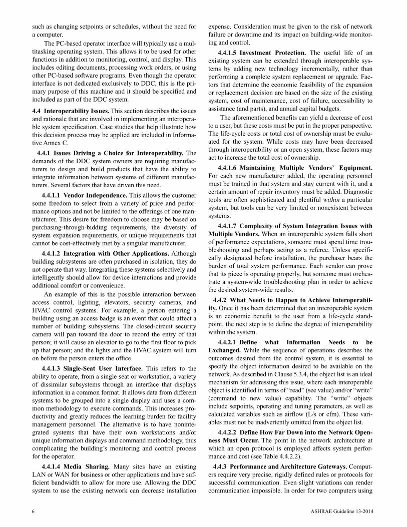
such as changing setpoints or schedules, without the need fora computer.
The PC-based operator interface will typically use a mul-titasking operating system. This allows it to be used for otherfunctions in addition to monitoring, control, and display. Thisincludes editing documents, processing work orders, or usingother PC-based software programs. Even though the operatorinterface is not dedicated exclusively to DDC, this is the pri-mary purpose of this machine and it should be specified andincluded as part of the DDC system.
4.4 Interoperability Issues. This section describes the issuesand rationale that are involved in implementing an interopera-ble system specification. Case studies that help illustrate howthis decision process may be applied are included in Informa-tive Annex C.
4.4.1 Issues Driving a Choice for Interoperability. Thedemands of the DDC system owners are requiring manufac-turers to design and build products that have the ability tointegrate information between systems of different manufac-turers. Several factors that have driven this need.
4.4.1.1 Vendor Independence. This allows the customersome freedom to select from a variety of price and perfor-mance options and not be limited to the offerings of one man-ufacturer. This desire for freedom to choose may be based onpurchasing-through-bidding requirements, the diversity ofsystem expansion requirements, or unique requirements thatcannot be cost-effectively met by a singular manufacturer.
4.4.1.2 Integration with Other Applications. Althoughbuilding subsystems are often purchased in isolation, they donot operate that way. Integrating these systems selectively andintelligently should allow for device interactions and provideadditional comfort or convenience.
An example of this is the possible interaction betweenaccess control, lighting, elevators, security cameras, andHVAC control systems. For example, a person entering abuilding using an access badge is an event that could affect anumber of building subsystems. The closed-circuit securitycamera will pan toward the door to record the entry of thatperson; it will cause an elevator to go to the first floor to pickup that person; and the lights and the HVAC system will turnon before the person enters the office.
4.4.1.3 Single-Seat User Interface. This refers to theability to operate, from a single seat or workstation, a varietyof dissimilar subsystems through an interface that displaysinformation in a common format. It allows data from differentsystems to be grouped into a single display and uses a com-mon methodology to execute commands. This increases pro-ductivity and greatly reduces the learning burden for facilitymanagement personnel. The alternative is to have noninte-grated systems that have their own workstations and/orunique information displays and command methodology, thuscomplicating the building’s monitoring and control processfor the operator.
4.4.1.4 Media Sharing. Many sites have an existingLAN or WAN for business or other applications and have suf-ficient bandwidth to allow for more use. Allowing the DDCsystem to use the existing network can decrease installation
expense. Consideration must be given to the risk of networkfailure or downtime and its impact on building-wide monitor-ing and control.
4.4.1.5 Investment Protection. The useful life of anexisting system can be extended through interoperable sys-tems by adding new technology incrementally, rather thanperforming a complete system replacement or upgrade. Fac-tors that determine the economic feasibility of the expansionor replacement decision are based on the size of the existingsystem, cost of maintenance, cost of failure, accessibility toassistance (and parts), and annual capital budgets.
The aforementioned benefits can yield a decrease of costto a user, but these costs must be put in the proper perspective.The life-cycle costs or total cost of ownership must be evalu-ated for the system. While costs may have been decreasedthrough interoperability or an open system, these factors mayact to increase the total cost of ownership.
4.4.1.6 Maintaining Multiple Vendors’ Equipment.For each new manufacturer added, the operating personnelmust be trained in that system and stay current with it, and acertain amount of repair inventory must be added. Diagnostictools are often sophisticated and plentiful within a particularsystem, but tools can be very limited or nonexistent betweensystems.
4.4.1.7 Complexity of System Integration Issues withMultiple Vendors. When an interoperable system falls shortof performance expectations, someone must spend time trou-bleshooting and perhaps acting as a referee. Unless specifi-cally designated before installation, the purchaser bears theburden of total system performance. Each vendor can provethat its piece is operating properly, but someone must orches-trate a system-wide troubleshooting plan in order to achievethe desired system-wide results.
4.4.2 What Needs to Happen to Achieve Interoperabil-ity. Once it has been determined that an interoperable systemis an economic benefit to the user from a life-cycle stand-point, the next step is to define the degree of interoperabilitywithin the system.
4.4.2.1 Define what Information Needs to beExchanged. While the sequence of operations describes theoutcomes desired from the control system, it is essential tospecify the object information desired to be available on thenetwork. As described in Clause 5.3.4, the object list is an idealmechanism for addressing this issue, where each interoperableobject is identified in terms of “read” (see value) and/or “write”(command to new value) capability. The “write” objectsinclude setpoints, operating and tuning parameters, as well ascalculated variables such as airflow (L/s or cfm). These vari-ables must not be inadvertently omitted from the object list.
4.4.2.2 Define How Far Down into the Network Open-ness Must Occur. The point in the network architecture atwhich an open protocol is employed affects system perfor-mance and cost (see Table 4.4.2.2).
4.4.3 Performance and Architecture Gateways. Comput-ers require very precise, rigidly defined rules or protocols forsuccessful communication. Even slight variations can rendercommunication impossible. In order for two computers using

ASHRAE Guideline 13-2014 7
different protocols to communicate, some kind of translationmust take place. The device that performs this translation iscalled a gateway.
Gateways are sometimes confused with routers becausegateways also perform routing tasks in addition to translation.The distinction between a gateway and a router is important.
4.4.3.1 Routers. Like a gateway, a router is used to con-nect two or more communication networks. Routers and gate-ways filter message traffic because messages pass throughonly if the source of the message is on one side and theintended destination is on the other. The difference is that fora router, the connected networks all use the same applicationprotocol messages. Translation is not needed. A router’s job isto forward the message to the next network in the path to itsdestination. This makes routers much more simple than gate-ways.
For example, compare sending a message between twodifferent networks to sending a letter from an intra-office mailsystem through a postal service to its destination. Using thisanalogy, a router removes the letter from the intra-office enve-lope, puts it in a postal service envelope, addresses the enve-lope, puts the correct postage on it, and sends it on its way.The letter itself remains unchanged. A gateway, on the otherhand, opens the letter, translates it into another language (ifpossible), puts it into a new envelope, re-addresses it, andthen sends it on.
4.4.3.2 Gateway Benefits and Limitations. No universalright answer exists to the question: Is it a good idea to use agateway in a BAS? Careful consideration of the benefits andlimitations of the costs of the gateway in comparison to otheroptions is needed before making a decision. The most impor-
tant step in evaluating the use of gateways is to determinewhat information needs to be exchanged:
• What information is critical?• What information is important but not essential?• What information is desirable but not worth significant
additional expense?• What kind of future expansion is anticipated?
Benefits
a. In some situations a gateway can provide connectivitybetween devices that would not be possible any other way.
b. A gateway can create a competitive bidding situation. Thefinancial savings resulting from competition may makethe limitations and cost of the gateway worthwhile.
c. Gateways provide a way to retain installed proprietaryequipment that is still functioning satisfactorily, whilemigrating toward open, interoperable systems in a step-by-step manner as the proprietary systems and compo-nents reach the end of their useful life.
d. A gateway can provide the opportunity to allow connec-tivity between different BASs, such as life safety andHVAC control, yet maintain the integrity of the criticallife safety systems. The gateway can integrate and manageboth systems, while at the same time retaining some isola-tion because the gateway limits the interaction.
Limitations
a. All gateways have finite information storage and process-ing resources. The gateway must somehow map the infor-mation and concepts from one protocol to another.Specifications for gateways must clearly state what infor-
TABLE 4.4.2.2 Open Protocols
Opens at this Level Provides these Benefits Adds these Costs Best Use
Informationmanagement level
Allows clusters of different brandsof control systems to pass informationto a host system that can view allsystems in a common format.Fundamental overrides andcommands can be performed atthe host.
At least one gateway (dependsupon gateway’s object) per eachadditional brand of control system;additional host hardware andsoftware if none of the existingcontrol systems can act as host;programming of each gateway.
Multiple building complexes where oneor more buildings have a different brandof control system and there is a need forsingle-seat user interface.
Supervisory level Same as previous level, plus:information is passed betweenclusters of control systems to allowfor global control interoperability(outside air temperature sensingdemand limiting, etc.).
At least one gateway (dependsupon gateway’s object) per clusterof control systems; programmingof each gateway; programming ofeach cluster to incorporate globalinformation and interaction.
Multiple building complexes or large,singular building complexes where thereis a need for limited, distributedinformation access, single-seat userinterface, and global interprocessinteraction.
Controller level Allows different brands of dedicatedcontrollers to be connected on thesame bus and provides for globalcommunications, global control, andinter-process interaction.
Unless the controllercommunicates using an openprotocol, a gateway must be addedper each controller or each group ofsimilar controllers.
Systems that have few controllers andare spread out over a large area.
Field device level Allows for multiple addressable fielddevices (temperature sensors,actuators, etc.) to communicate onone pair of wires.
Each field device must have specialdigital addressing capability.
Systems in which field devices arespread out over a large area and/or arerunning multiple wires are very costly.

8 ASHRAE Guideline 13-2014
mation must be available through the gateway and howmuch future expansion is required. Often, using a gatewaywill require a compromise between getting all the desiredinformation and keeping within the budget.
b. Gateways have a limited ability to translate dissimilarconcepts. Simple concepts, such as temperatures and on/off status, are generally easily translated. However, prob-lems arise for more complex concepts, such as schedules,alarms, prioritized commands, and trending data. In somecases, one or more of these functions simply will beimpossible to do through the gateway.
c. Many control systems provide a way to program or con-figure controllers over the network. It is usually not possi-ble to accomplish these tasks by passing messagesthrough a gateway. Instead, a separate connection thatbypasses the gateway is usually required.
d. Failure of the gateway results in a loss of communicationbetween all devices on opposite sides of the gateway.
e. Gateways can introduce time delays when attempting toretrieve information. What happens, for instance, if thegateway passes previously stored data that are now obso-lete? Will the recipient be able to tell the difference?
f. Gateways make troubleshooting network problems moredifficult. Different tools are needed to see and interpret theprotocols on both sides of the gateway. Even the limitationin the amount of information accessible through the gate-way can make troubleshooting difficult because it may notbe possible to access all of the information needed todiagnose the problem.
g. The throughput or speed of the gateway may make access-ing data a slower process. This issue should be carefullyconsidered and included in the performance criteria speci-fication.
A gateway is a useful and effective tool to achieve lim-ited connectivity between otherwise incompatible devices. Asthe amount and variety of information that needs to beexchanged increases, the viability of using a gateway toaccomplish the task diminishes.
4.4.4 Define the Open Protocol to Be Used. It is neces-sary to specify the protocol to be used in an open system inorder to drive communication conformance toward that cer-tain set of criteria or standards. In every case of writing aninteroperable specification, the designer must specify whichopen protocol is to be used in each network segment. This isespecially important if he or she is integrating equipment con-trollers (such as chiller and boiler controls or lighting con-trols) that are specified elsewhere and supplied bymanufacturers other than the building controls’ manufacturer.Otherwise, the goal of integrating with these other applica-tions will be left to chance.
4.4.4.1 Categories of Protocols. The word standard isoften used in discussions of protocols. There are degrees ofpropriety to the standards continuum, and they can beexplained as follows:
• Industry recognized standard. A protocol that is formallyrecognized and/or listed by an independent, industry stan-dards organization as a set of operational criteria. Exam-
ples are BACnet (recognized by ASHRAE and ANSI) andLonTalk (EIA).
• Defacto standards. Very popular proprietary protocols inthe marketplace that have been embraced by users andmanufacturers and are offered as communications optionson a variety of equipment. Examples include Modbus,Allen Bradley DH+, and Opto 22.
• Proprietary standards. A manufacturer makes proprietaryprotocols available on a limited basis or shares the proto-col with the public at large for use in integrating otherproducts into that manufacturer’s network.
These classifications may be helpful in understanding thetype of endorsement and support a protocol may have but donot suggest how popular or how broad the base of users maybe. Some protocols of major control system manufacturersare also implemented by a defined, but limited, number ofother manufacturers to bring a broad-based, interoperablesolution to the market. The size of that number may exceedthe number of solutions possible through the use of an indus-try-recognized or defacto standard.
4.4.4.2 Customer Satisfaction. The protocols you spec-ify will limit the number of companies to those that can offera solution. The customer, or end user, of the system must ulti-mately feel comfortable with those manufacturers’ products.Also, the total number of companies able to offer the solution(which could be limited to just one or two) must be accept-able. These issues should be considered in advance in order toavoid disappointment with the interoperable solution, eventhough the technology may be functional.
4.4.4.3 Case Studies in Annex. Each interoperable solu-tion depends on the factors surrounding the client’s needs.Two case studies have been assembled in Informative Annex Cin order to illustrate how project and client needs drive the var-ious interoperable decisions and dimensions.
5. DESIGN AND CONSTRUCTION OFDIRECT DIGITAL CONTROL (DDC) SYSTEMS
The following section describes the steps involved in pro-viding a DDC system from design through the end of war-ranty. The engineer is the focal point for many of these stepsand the contractor will be responsible for implementing thesteps. If these steps are performed properly, the end result willbe a satisfied client with a DDC system that runs the facilityin the most efficient manner.
5.1 Steps in Providing a DDC System. The steps involvedin providing a DDC system are shown in Figure 5.1.
5.2 Defining Project Scope. The engineer must use cautionto design a DDC system that meets the users’ needs. Someusers will have very basic needs. Others may require an exten-sive degree of alarm management and reporting. The complex-ity of the system has a direct relation to the project cost.
The assessment of the desired features is a continual pro-cess that must be weighed against the proposed budget for theproject at key stages. The features must be prioritized so thatthe low-priority items can be removed during the design stageif necessary to stay within budget.

ASHRAE Guideline 13-2014 9
The engineer begins by asking the following questions:
• What is the size of the project?• What is the building’s proposed use?• Is the property owner-occupied or leased• Do special control needs exist, such as low cost, high
accuracy, comfort, or lowest energy use?• Who will run the building and what are their capabilities?• Does the owner have other buildings that will be con-
nected to this site?• What is the proposed HVAC system?• What is the HVAC and controls budget?• Is the project a retrofit? If so, what control system is pres-
ently installed and will it need to be expanded orreplaced?
Based on this information, the engineer should be able tobegin designing and establishing the project budget. Theengineer needs to confirm the preliminary design with theowner based on the above information.
Once the facility’s needs have been defined in terms ofthe number of HVAC systems, user requirements, number ofpoints, and criteria, the system designer can complete thedesign of the DDC system.
If an owner desires to include performance monitoring aspart of the project requirements, the specification will need todefine the functional capability that is desired. This includesthe required monitoring points and performance metrics, sys-tem accuracy, network throughput and enhanced data man-agement, and graphical data displays. Detailed examplespecifications can be found in Informative Annex D.
5.3 Designing the DDC System5.3.1 Steps in Creating the Contract Documents. Once
the project scope is well understood, the engineer can beginsystem design. There are several methods for achieving this,
and the correct method is up to the individual designer. Themethod recommend by this guideline is as follows:
a. Isolate each unique type of system for the project. If mul-tiple systems are used, a single typical system can be cre-ated, and minor modifications can be shown. A systemmay be an air handler with VAV boxes, chiller plant,boiler, heat recovery, smoke control, or other.
b. For each system, the engineer should produce a systemschematic drawing. This is a very basic illustration that isschematic in nature. The drawing will need to show thecritical control components. See Clause 5.3.2, “CreatingProject Drawings,” for examples and details on creatingproject drawings.
c. Using the drawings, create the sequences of operation.When creating a sequence, you must determine what thesystem will need to do under a variety of circumstances.For example, what should the system do when the build-ing is occupied or when it is unoccupied, during the sum-mer, or during the winter? What happens during a fireemergency or during a power failure? The sequence willneed to answer all of these questions. See Clause 5.3.3,“Sequences of Operation,” for examples of and details oncreating sequences.
d. With the sequence and the system drawing, the engineercan now prepare a system object (or points) list. This is animportant system document that shows which hardwareand software points the contractor will need to provide,along with the key functions of these points. See Clause5.3.4, “Object List,” for examples of and details on creat-ing object lists.
e. Add control elements to mechanical and electrical draw-ings. The project drawings that have been prepared formechanical (Division 15 of this specification) and electri-cal (Division 16) will need to show DDC elements. Thesewill typically include space and outdoor sensor locationson the floor plans, damper locations and schedules on themechanical plans, and locations of control panels requir-ing 120 VAC on the electrical plans.
f. Create the project specifications. In reality, the engineerwill rarely sit down and create a DDC system specifica-tion from scratch. Most engineers have built up a series of“master specifications” that can be edited to meet theneeds of a project. Many of these specifications were orig-inally obtained from controls companies and have beenrefined over many years of use. The master specificationwill provide a good starting point for producing an unbi-ased document, but it must be edited to suit the consider-ations of each individual project.
The sequences of operation and the object list can appeareither in the system drawings or in the written specification.These project documents should only appear in one place.Placement of the documents in the project drawings will tendto ensure that they are kept as part of the building record.Placing the documents in the specification will make themeasier to be transmitted to potential bidders by fax.
5.3.2 Creating Project Drawings. Control drawings (seeFigure 5.3.2) are a critical element in documenting the system
FIGURE 5.1 Steps in providing a DDC system.

10 ASHRAE Guideline 13-2014
design. A drawing shows the contractor the physical relation-ships of various components, such as fans and coils. The con-trol devices can be accurately located relative to the systemcomponents (e.g., the freezestat should be shown upstream ofthe heating coil). Flow diagrams showing a schematic layoutof piping and equipment should be provided for steam, hot-water, and chilled-water systems. Control devices (sensorsand valves) should be shown in the appropriate locations inthe piping.
The benefits of including control drawings as part of thecontract documents include the following:
• There is a graphical depiction of the design for the con-tractor.
• There is a clearer definition of the control hardwarerequirements.
• Control drawings allow the designer to see the overalldesign concepts and verify the implementation of theseconcepts.
• The drawings facilitate system checkout during both theshop drawing and installation phases of the project.
• Since the drawings depict the hardware types and loca-tions, all of the bidders are on the same page.
Preparation of drawings takes time and money. Theresources used in control drawing preparation are paid back inseveral ways:
• They help define project scope and reduce prebid ques-tions.
• Shop drawing preparation and review are expedited.• Bid pricing is more uniform.• Fewer change orders may result from documentation mis-
understandings.
5.3.3 Sequences of Operation. The sequences of operationdescribe how the system shall function and are the designer’sprimary method of communication to the control system pro-grammer. A sequence should be written for each system to becontrolled. In writing a sequence, care must be taken todescribe all operational modes and to ensure that all I/Odevices needed to implement the sequence are shown on theobject list and drawings.
5.3.3.1 Writing Control Sequences. Writing clear,unambiguous, concise yet comprehensive sequences of con-trols is very difficult. It first requires a clear understanding ofhow controls work, the limitations of the specific controlshardware specified, the limitations of the HVAC systemdesign, and a knack for clear thinking and writing. It alsotakes practice and experience. The following are suggestionsto assist in developing successful control sequences:
• Provide a description of the system at the beginning ofeach section to assist the reader in understanding the sys-tem. This should include unusual or custom system orcontrol requirements to help explain the rationale behindsequences.
• Organize sequences into the logical hierarchy of systemsand the subsystems they serve. The most energy-efficientsequences usually start at the lowest level and feed opera-tional requests upward. For example, zone VAV controllogic determines the need for heating and cooling, whichis conveyed to the air handler that serves them so that theyoperate as desired. The air handler control logic, in turn,conveys the need for chilled and hot water to the centralcooling and heating plants. In this way, systems operateefficiently and only when needed.
• Use tables and diagrams where possible to assist in con-veying sequencing logic.
FIGURE 5.3.2 Sample control schematic.