askaynak - tra 161-ul inverter expressweld... expressweld model : inverter 161-ul tra mma w user...
TRANSCRIPT

www.askaynak.com.tr
Expre
ssw
eld
Model : I
nve
rter
161-U
LTRA
MM
A W
eld
ing M
ach
ine
USER MANUAL
Warranty Period and Specifications
MMA Arc Welding Machine
Welding Method and Specifications
220V - 1Ph 2.5 - 4 mm Phase

Safety in Welding
General Specifications
Installation and Operator Instructions
Preparation and Operation
Maintenance & Troubleshooting
Electromagnetic Compatibility
Efficient Use of Machine in Terms of Power Consumption
Transport and Storage Conditions
Expiry of Machine's Physical Life
Electrical Connection Diagram
Technical Service and Other Contact Adresses
3 - 4
5
6
7 - 9
10 - 13
14 - 15
15
15
16
19 - 20
21
Table of Contents
December 2014
Kaynak Tekniği Sanayi ve Ticaret A.Ş.
TOSB - Taysad Organize Sanayi Bölgesi, 2. Cadde, No: 5, 41435 Çayırova, KOCAELİ - TURKEY
Tel: (+90262) 679 78 00 Faks: (+90262) 679 77 00
www.askaynak.com.tr
This product was manufactured in China by
Kaynak Tekniği Sanayi ve Ticaret A.Ş.
Physical life determined by Ministry of Industry and Trade is 10 years.(This is the period for providing spare parts required for the machine to operate.)
MANUFACTURER
Unpacking 16
Spare Parts 17-18

"MARKA Tescil Belgesi" Eklenecek.

Safety in Welding - 1
Only qualified personnel should use this machine. Be sure that all installation, operation,
maintenance and repair procedures are performed only by qualified person. Before operating the
machine read and understand the operation manual. Failure to observe instructions stated in this
manual may cause serious personal injury, death and damage the machine. Please read the
cautions stated with above symbols. Kaynak Teknigi Sanayi ve Ticaret A.S. is not responsible for
damages caused by improper installation, improper storage or abnormal operation.
WARNING: This symbol indicates that instructions must be followed to avoid serious
personal injury, loss of life or damage to this equipment. Protect yourself and others.
READ and UNDERSTAND INSTRUCTIONS: Read and understand this manual
before operating this equipment. Failure to follow the instructions in this manual may
cause serious personal injury, loss of life, or damage to this equipment.
ELECTRIC SHOCK MAY KILL: Welding machine produces high voltage that may be
harmful for human health. Do not touch the electrode, ground connection or electrically hot
parts while machine is operating. Isolate yourself against electrode, ground connection or
work piece. Since the risk of electrical shock exists, do not touch the metal ends of the plug
after it has been removed from the power.
FUMES and GASES MAY BE DANGEROUS: Welding operation produce fumes and gases
hazardous to health. To protect the users from this danger, there should be enough
ventilation or fumes and gases should be thrown away from the breathing zone.
WELDING ARC MAY BURN: Proper mask, filter and protective glass should be used to
protect your eyes from sparks and the rays of the arc when welding or observing. Skin
should be protected with flame-proof clothing. Protect nearby personnel with suitable, non-
flammable screening and warn them not to watch the welding arc or expose themselves to
the arc rays.
WELDING SPARKS MAY CAUSE FIRE or EXPLOSION : Keep the flammable materials
away from the welding area and put the fire extinguisher on an easily accessible place.
Remember that welding sparks and hot materials from welding can easily go through small
cracks and the most tight openings to adjacent areas. Do not weld on any jerrycan, barrel,
tank or material if you are not sure that precautions were taken to avoid flammable and
poisonous gasses totally from the environment. Never operate this equipment when
flammable gases, vapors or liquid combustibles are present.
This machine has been designed to make manual metal arc welding
and it can not be used for any other purposes.
3

ELECTRICALLY POWERED EQUIPMENT: Turn off input power using the switch at the fuse
box before working on the equipment. Electrical connections should be performed
adequate to the obligated rules.
GROUNDING: For your safety and trouble-free operation, electrical supply cables should
be connected to a proper grounded receptacle.
ELECTRICALLY POWERED EQUIPMENT: Check the conditions of electrode cables,
supply cables and the cables connected to the machine regularly. If you face an improper
condition, replace the defective parts with the new ones immediately. In order to prevent the
risk of arc explosion and fire, do not leave the electrode holder directly on the welding table
or on a surface that is contacting with the work clamp.
ELECTRIC and MAGNETIC FIELDS MAY BE DANGEROUS TO HUMAN HEALTH:
Electric that flows through conducters, produces electromagnetic field. This
electromagnetic field can be effective on devices like pacemakers. Users who have a
pacemaker must refer to a physiotherapist before operating the machine.
GAS CYLINDER MAY EXPLODE: Only use the compressed gas cylinders that contain
protective gas which is adequate for welding processes. Be sure that adequate regulators
for the gas and cylinder are correctly mounted on the cylinder. Always keep cylinders in an
upright position and securely chained to a fixed support. Do not change the places of the
cylinders before closing the protective covers. Avoid contact between electrodes, electrode
holders, work clamps and electrical parts with the gas cylinder. Stockpile the cylinders at a
distance from the areas that is called heat and spark producing.
WELDED MATERIAL MAY BURN: Welding generates a large amount of heat. Hot surfaces
and materials can cause serious burns. Gloves should be worn while touching and carrying
this type of materials.
SAFETY MARK: This machine is suitable for supplying power for welding operations carried
out in an environment with increased hazard of electric shock.
Safety in Welding - 2
4

General Specifications
EXPRESSWELD Inverter 161-ULTRA, is an inverter welder which is produced with the latest inverter technology.
Power source unit with inverter, is a technology that is introduced to the market in 1980. 50Hz/60Hz frequency is converted to 20 KHz or above, which means high frequency, by IGBT and then voltage is decreased and alternating current (AC) is converted to direct current (DC), a powerful DC source current is created by using PWM technique in inverter technology, the size and weight of the welding machine is decreased and the efficiency is increased by 30% with inverter technology. The most important specifications of the welding machines that is produced with inverter technology are providing stabile arc, safety, lightness and energy saving. The improvement of welding machines with inverter is called a revolution in welding area by experts.
1 - High quality welding with proper DC current,2 - Stabile welding arc,3 - Easy controlling of molten welding puddle,4 - Easy electrode ignition with high open circuit voltage,5 - Application area width,6 - Lightness,7 - Easy installation and operating,8 - 2 years limited spare parts warranty after purchasing date.
The advantages of EXPRESSWELD Inverter 161 :-ULTRA
Input
Input Voltage220 V ± % 15 /
Input Power5.2 kW (25% duty cycle)
Frequency50/60 Hertz (Hz)
Welding Current - Output Rating
Duty Cycle(10 minutes period)
25%60%
Output Current (Amp.)
155 A100 A
Output Voltage26.2 V (DC)24.0 V (DC)
Output Range
Welding Current Range30 - 160 A
Maximum Open Circuit Voltage60 V (DC)
Physical Properties
Height260 mm
Width135 mm
Length365 mm
Weight7,3 kg
Operating Temperature : Between - 10°C and + 40°C
Fuse Size and Type : 32 Amp. (Delayed)
Power Factor (cos ) : 0.72
100% 80 A
(Volt)
23.2 V (DC)
Insulation Class : H
Pollution Degree : 3
Input Cord : 3 x 2.5 mm²
~ 1 Ph
5

Installation and Operator Instructions
Read this entire section before installation or operation of the machine.
Location and Environment:
However, it is important that simple preventative measures are followed to assure long life and reliable operation.
1 - Do not put or operate the machine on a surface that is inclined above 15°.
2 - The machine must be operated in an environment with fresh air flow and there musn't be any factor that blocks or stops the ventilation or fresh air flow. The machine shouldn't be covered with paper or similar things while operating.
3 - Dust and dirt may get into the machine. This condition should be minimized. Do not work in environments that contain dense dust, grinding dust, corrosive gases and in atmospheres with water, paint or oil particles.
4 - This machine is IP21S protection class. Keep it dry when possible and do not place it on wet ground or in puddles.
5 - This machine is designed for indoor use. Never operate the welding machine under sunlight and when there is a possibility of water splattering.
6 - Put the machine away from radio controlled devices. Normal operation may adversely affect the operation of this type of devices, which may result in injury or equipment damage. Read the electromagnetic accordance section in this manual.
7 - Do not operate this machine in ambient temperatures of less than -10°C and over +40°C and 80% humidity.
8 - If people who are unqualified about electrical equipments, opens the work cover and interfere with the machine, they may face life threatining conditions. People who behave otherwise is considered to accept the negative results.
9 - This welding machine is designed for light welding processes performed by using 2.50 and 3.20 mm diameter rutile and basic type stick electrodes.
Duty Cycle and Overheating:
The efficiency of the machine is the percentage of the rating of the welder performing welding process without overheating and stopping for 10 minutes with the welding current given.
Machine is protected from overheating by its thermal protection. When this protection is enabled the warning light on the front panel lits. When you return to the safe operating temperature the light turns off and you may continue welding.
6
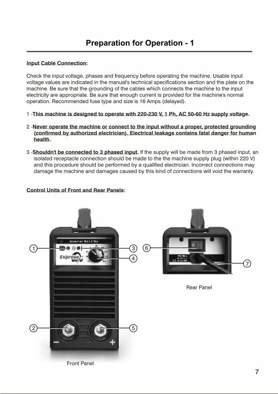
Rear Panel
Preparation for Operation - 1
Input Cable Connection:
Check the input voltage, phases and frequency before operating the machine. Usable input voltage values are indicated in the manual's technical specifications section and the plate on the machine. Be sure that the grounding of the cables which connects the machine to the input electricity are appropriate. Be sure that enough current is provided for the machine's normal operation. Recommended fuse type and size is 16 Amps (delayed).
1 -This machine is designed to operate with 220-230 V, 1 Ph, AC 50-60 Hz supply voltage.
2 -Never operate the machine or connect to the input without a proper, protected grounding (confirmed by authorized electrician). Electrical leakage contains fatal danger for human health.
3 -Shouldn't be connected to 3 phased input. If the supply will be made from 3 phased input, an isolated receptacle connection should be made to the the machine supply plug (within 220 V) and this procedure should be performed by a qualified electrician. Incorrect connections may damage the machine and damages caused by this kind of connections will void the warranty.
Control Units of Front and Rear Panels:
Front Panel
7
6
7
2 5
1 3
4

Components of Front and Rear Panels :
3 - Overload / Thermal Warning Light: This lamp lights when the machine can not give output current because of overheating. You can face this condition when the ambient temperature is over 40°C and when the machine's on time ratio (operating efficiency) is exceeded. Leave the machine open and let it cool down. When the light turns off, the machine is ready to use again.
5 - Positive (+) Welding Cable Connection: Positive output connection for the welding current.
6 - On/Off Switch: Controls the entry of the input current input to the machine.
7 - Input Cable: The plug and the supply cable which the machine will be connected to the input.
Stick Electrode Welding :
Following procedures should be performed before starting welding process:
1 - First of all decide the adequate pole for the used electrode. You can find this information in the electrode's information sheet. After that connect the welding cables to the outputs in accordance with the selected pole. For example if DC (+) will be used, you should connect the electrode cable to the machine's (+) output (5) and the grounding clamp (-) output (2). Insert the socket with guide pim facing the upper side into its slot and then rotate clockwise for 1/4 tour. Be sure that the socket fits its slot safely and without tightening too much. Otherwise, usage for a long time and conditions in which the welding current is high, loose sockets may burn because of overheating. Change the cable connections for the electrodes that will be used in DC (-) to electrode cable (-) output (2) and grounding clamp (+) output (5). Selecting the wrong pole may cause unstabile arc, spatter and sticking of electrode to the workpiece.
2 - Insert the electrode to the electrode holder.
3 - Insert the work clamp's opening to the unpainted, rustless and clean surface of the workpiece and make sure it completely fits with the opening.
4 - Insert the input connection plug to the adequate receptacle.
5 - Perform the mentioned controls below before starting the welding process.
a - Make sure that the welding machine is safely grounded.
b - Make sure that all the contact surfaces and especially the connection between the clampon the work cable's end and the workpiece is secure.
8
Preparation for Operation - 2
1 - Power Light: Indicates, machine is working.
2 - Negative (-) Welding Cable Connection: Negative output connection for the welding current.
4 - Welding Current Control Button: Adjusts the machine's output current (source amps).

c - Check the welding cables if they are connected correctly or not.
d - Welding sparks and spatters may cause fire. For this reason avoid keeping flammable materials in the welding environment.
6 - Open the "On/Off Switch" (6).
7 - Adjust the average welding current value with "Welding Current Control Button" (4) and due to electrode diameter, type, welding position and electrode information sheet. Generally the welding current is between the values that is mentioned below. However it would be useful if you adjust the stick welding electrode due to indicated values in the producer firm's catalogue.
This welding machine is designed for light welding processes performed by using 2.50 and 3.20 mm diameter rutile and basic stick electrodes.
Welding Currents for Rutile and Basic Type Coated Electrodes :
ø 2.5 mm : 70 - 100 Aø 3.2 mm : 100 - 140 A
Welding current can be precisely adjusted due to welding condition while welding.
Supplied Accessories
Welding cableWork cable
9
Preparation for Operation - 3

DAILY MAINTENANCE
Observe whether the current potentiometer on front panel and on-off switch on rear panel are located correctly and operating well. If they are not secured correctly well, contact to technical service.
Observe if there is any strange sound, smell or vibration when machine is working. If there is, try to find the cause, if you can’t find, contact to technical service.
Be sure that the welding current is the same with the adjust value. If the current is not the same, adjust and calibrate it.
Be sure that the fan works well. If fan doesn’t work even the machine is very hot, check whether there is something blocked in the blade. If the fan is broken, contact to the technical service.
Check if the welding connectors are loose or overheated. If there is a problem, connectors must be tightened or replaced.
Check if the insulation of the welding cables are defected. If they are defected, insulate the part with an appropriate material or replace the cable.
MONTHLY MAINTENANCE
The dust that is accumulated inside the welding machine should be cleaned by pressured air. If the machine is used in an environment which contains too much dust and fume,this procedure should be performed twice a month. To protect small parts, be careful about the air pressure while cleaning
Check the screws on the machine, loose ones must be tightened. If any screw is missing put a new one. Replace the rusty screws.
QUARTER YEARLY MAINTENANCE
Check whether the actual welding current is the same with the displaying value. You can measure the current with clampmeter
Maintenance & Troubleshooting - 1
In order to work the welding machine with high efficiency and in safe, periodical maintenance is required. The operator is supposed to understand the maintenance procedures, to be used to machine, to be able to make basic controls by self, and eliminate the operator mistakes. Maintenance details are given below.
Warning : Machine must be unplugged from the mains supply during maintenance.
10

This machine is checked aginst any kind of problems before it is dispatched from the factory. That’s why don’t let anyone who is not authorized by our company to change any equipment.
Maintenance & troubleshooting must be performed by the technical services authorized by Kaynak Tekniği Sanayi ve Ticaret A.Ş.
To protect small parts, be careful about the air pressure while cleaning.
Maintenance must be done very carefully. If any wire, cord gets flexible or misplaced, it may be hazardous for the operator.
Avoid water or vapour getting inside the welding machine. If the machine is effected by humidity, it should be dried up and its isolation should be checked.
If the welding machine won't be used for extended periods, it should be placed inside the plastic package and kept in a dry environment.
When lifting, the welding machine shouldn't be thrown randomly and be protected from blows.
Maintenance & Troubleshooting - 2
1 -
2 -
3 -
4 -
5 -
6 -
Fuse trips while the machine's main switch is open.
Input filter board isdefective.
Refer to the service.
Machine doesn't work, There is no output, Fan doesn't work.
No electricity on theline.
Check the phases' voltage which enters the machine. Reconnect the phases.
Main input cable isdefective.
Check the main input cable. Replacewith a new one if it is necessary.
On/Off switch isdefective.
Replace the button. Contact to the serviceif necessary.
Input filter or powerboard is defective.
Contact to the service.
Arc is not stable, Welding is not proper.
Pole connections are incorrect or poor.
Change the poles and tighten theconnections.
Voltage value is notadequate.
Is input voltage 220 Volts? Is extensioncable's length and section suitable?Check it. Correct it if not.
TROUBLE POSSIBLE ERROR SOLUTION
7 -
11
Caution! For every kind of maintenance and repair operations, contact to the nearest authorized Kaynak Teknigi Sanayi ve Ticaret A.S. technical service. Maintenance or repairs performed by unauthorized
technical services or personnel will void the manufacturer’s warranty.

Maintenance & Troubleshooting - 3
TROUBLE POSSIBLE ERROR SOLUTION
Machine vibrates while working.
It’s not on a stable place
Place it on a stabe floor.
No OCV.
Fan is broken. Check the fan, contact to service if necessary.
The power light is on but fan doesn’t work
Fan is broken. Contact to the technical service.
Machine is broken. Contact to the service.
There is no welding current.
Welding cables are not connected.
Connect the cables.
Welding cables are defected.
Replace the cables.
Earthing cable is not connected to workpiece.
Connect the earthing cable.
Arc doesn’t start or electrodes stick to workpiece.
Improper connections.
Check the connections.
Work piece is dirty, greasy or there istoo much dust on it.
Clean the workpiece.
Current cannot be adjusted.
Adjust potentiometer is broken or poorly connected
Contact to the service.
Current is too low. Adjust the current.Poor penetration.
12
It makes a strange sound and smell.

Maintenance & Troubleshooting - 4
TROUBLE POSSIBLE ERROR SOLUTION
Arc blow. Airflow disturbance Avoid air disturbance.
Electrode is eccentric Adjust the electrode angle.
Magnetic effect. Incline the electrode to the opposite way of magnetic flow.
Change the position of earth clamp or add earth cable on the two side of the workpiece.
Use short arc.
Thermal indicator Over heat protection. Reduce welding current or working time.
Over current protection.
Contact to the service.
Change the electrode.
13
lamp lights.

Electromagnetic Compatibility - 1
This machine has been designed in accordance with all norms and rules. However, it may still generate electromagnetic emissions that can affect telecommunication devices (telephone, radio, and television) and other safety systems. This condition, can cause safety problems in the affected devices. Read this section carefully to eliminate or reduce the amount of electromagnetic emissions (interferences) generated by this machine.
This machine has been designed to operate in industrial areas. To operate in living quarters, it is necessary to observe particular precautions to eliminate possible electromagnetic emissions. The operator must install and operate this equipment as described in this manual. If any electromagnetic interference emission is detected the operator must put in place corrective actions to eliminate these emissions with, if necessary, assistance from Kaynak Teknigi Sanayi ve Ticaret A.S.. Changes shouldn't be made without Kaynak Teknigi Sanayi ve Ticaret A.S.'s written confirmation.
Before installing the machine, the operator must check the work area for any devices that may malfunction because of electromagnetic emissions. Following items should be considered about this subject.
1 - Input and output cables, control cables, and telephone cables that are adjacent to the work area and the machine.
2 - Radio and/or television transmitters and receivers, telecommunication equipments.
3 - Computers or computer controlled devices.
4 - Safety and control equipment for industrial processes.
5 - Personal medical devices like pacemakers and hearing aids.Since the electromagnetic fields can cause of failure on some types of pacemaker, the welder using pacemaker must consult the doctor prior to start welding.
6 - Equipment for calibration and measurement.
After the power unit is "ON", to make the machine electrically stabilized, the welding operation should be started after 5-10 seconds hold-on duration.
While welding, do not switch the on-off swich alternately "ON" or "OFF". This operation can cause voltage fluctuations and can also shorten the service life of the machine.
14
This welding machine is designed to consumpt less power comparing to conventional
machines.
Electromagnetic Compatibility - 2
Efficient Use of Machine in Terms of Power Consumption
Check the electromagnetic immunity for equipment operating in or near the work area. The
operator must be sure that all equipment in the area is compatible. This may require additional
protection measures.
Consider the following warnings to reduce the effect of electromagnetic emissions generated by
this machine.
1 - Mains supply connection should be performed as explained in the user manual. If electromagnetic
interference occurs, it may be necessary to take some precautions like filtering the electric main.
2 - The output cables should be kept as short as possible and should be directed as assembled or
banded together. These cable should never be wrapped around the body, anyone should
never stay on the midst of the cables and care should be taken for placing the cables on the
grounded surfaces.
3 - The ground cable should be connected to the work-piece under consideration as near as
possible.
4 - During the welding process, it should be stood away from the machine as far as possible.
5 - To reduce electromagnetic interference and increase work safety, ground the work piece if possible.
User should check if this grounding may cause problem for himself and for the machine.
6 - Ideal measurements of the working area should be determined based on the construction of this
area and other factors included.
7 - In case the machine used in environments having high electromagnetic fields, adjusted welding
current may change.
8 - To provide conformity with EN 61000-3-12 standard for this machine, it is the user's responsibility
to connect the machine to the mains with a suitable harmonic filter.
Transportation and Storage Conditions
When it is not in use, to protect the machine from the dust and the other possible contaminants in
the environment, and particularly when transferring it for long distance, place the welding machine
in its box. Do not drop the machine and pay attention against the strong mechanical shocks.
1 -
2 - To prevent excessive power consumption, current must be appropriate to the electrode
diameter and welding with unnecessarily high current must be prevented.
15

Expiry of Machine's Physical Life
16
When the economical life of the machine expired and cannot operate should not be disposed as
domestic waste and not thrown into waste. Welding machine should be disposed of as per local
regulations.
Unpacking
EXPRESSWELD Inverter 161-ULTRA welding machine is sold in its cardboard box. Do not purchase
the machines without packaging. For unpacking the machine, open top cover of the box and take the
machine out of its nylon bag. Keep this nylon bag and box and use to transport or to store the machine
in the future.
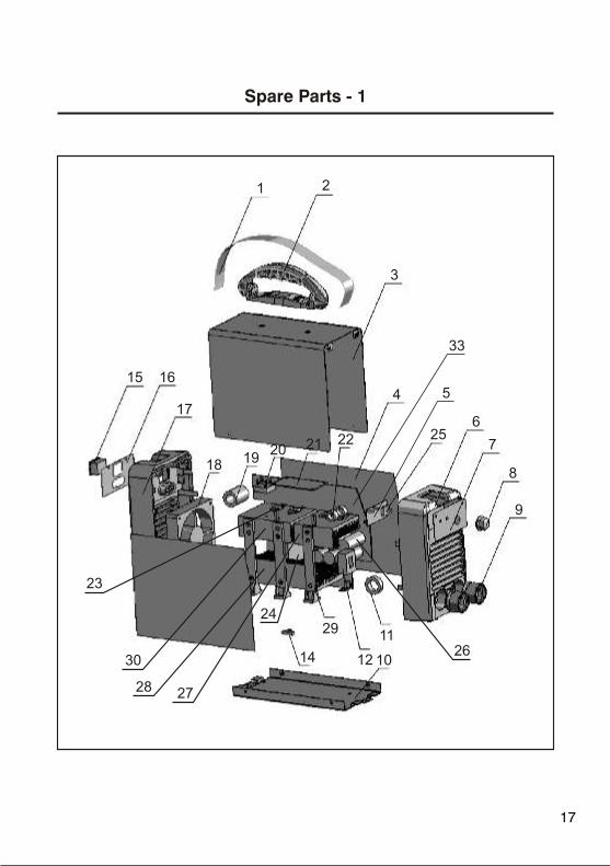
Spare Parts - 1
1 2
3
4
22 256
7
8
9
11
12 1014
29
15 16
17
18 1920 21
33
5
26
27
30
28
23
24
17

Spare Parts - 2
82U7511249
82U8253085
82U8301015-C
82U8713003
82U5496872-B
82U8069985
82U8103085
82U7458010
82U7152312
82U8055008
82U6271003-C
82U7321002
82U3200085
82U7231275
82U7232730
82U8103084
82U8068985
82U7720005
82U7735500
82U7411010
82U5496613-H
82U7735309
82U7425632
82U6185026-B
82U7456148
82U7460815
82U8425025
82U8425023
82U8123637
82U8425024
82U7421541
82U7406219
82U5496165-J
1
2
3
4
5
6
7
8
9
10
11
12
13
14
15
16
17
18
19
20
21
22
23
24
25
26
27
28
29
30
31
32
33
Part No. Part DescriptionNo.
Belt
Handle
Metal cover
Insulation plate
Front control PCB
Plastic front panel
Front label
Current adjust potentiometer knob
Welding current connection sockets
Metal base plate
Inductance coil
Current sensor (Hall)
Power System (Complete)
Thermal switch
On-Off switch
Rear label
Plastic rear panel
Fan
Magnetic core (Input cord)
Rectifier bridge
Control PCB
Magnetic core (Feedback)
Transistor
Main transformer
Capacitor (1500 µF)
Heatsink - 2
Heatsink - 1
Holder
Heatsink - 3
Output rectifier
IC TC 4420
Power PCB
Current adjust potentiometer
Quantity
1
1
1
2
1
1
1
1
2
1
1
1
1
1
1
1
1
1
1
1
1
3
4
1
1
6
1
1
3
1
6
2
1
18

Electrical Connection Diagram - 1
OC1 C2O
4-2 V
FAN
DR1
DR2
DR3
DR4K1 AC220-230/50/60HZ
PTC
-24V
21
43
AC
AC
IEMil rF te
Power PCB82U5496165-J
Control PCB82U5496613-H
19
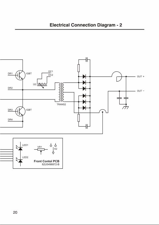
DR1 IGBT
DR3 IGBT
DR4
DR2
ED1L
LED2
K2VR1
TRANS2
O TU
O TU
O 1C
OC2
OC
Front Contol PCB82U5496872-B
Electrical Connection Diagram - 2
20

Dear customers
We would like you to abide the following recommendations.
Kaynak Teknigi Sanayi ve Ticaret A.S.
TOSB - Taysad Organize Sanayi Bolgesi2. Cadde, No: 5, Çayırova41435 Kocaeli - TURKEYPhone : +(90.262) 679 78 00Fax : +(90.262) 679 77 00
[email protected]@[email protected]
,
1 - Always get your "Warranty Certificate" ratified when you purchase the machine.
2 - Use your machine in accordance with the operating manual.
3 - When you need service, refer to our Technical Service Department which is in centre point of Istanbul or our Regional Sales Office or Authorized Retailer.
4 - When servicing process is over, do not forget to get "Service Form".
Technical Service and Other Contact Addresses
21

www.askaynak.com.tr
Kaynak Teknigi Sanayi ve Ticaret A.S.TOSB - Taysad Organize Sanayi Bolgesi, 2. Cadde, No: 5, Çayırova
41435 Kocaeli - TURKEYPhone: +(90.262) 679 78 00 Fax: +(90.262) 679 78 26
Manufacturer