asme geometric dimensioning
TRANSCRIPT

8/7/2019 ASME Geometric Dimensioning
http://slidepdf.com/reader/full/asme-geometric-dimensioning 1/19
ASME GDTP (Y14.M)
ASME Geometric Dimensioning
and Tolerancing Professional
Certification
Applicant Informatio

8/7/2019 ASME Geometric Dimensioning
http://slidepdf.com/reader/full/asme-geometric-dimensioning 2/19
STATEMENT OF POLICY
ON THE USE OF ASME
GDTP SYMBOLS AND
AUTHORIZATION IN ADVERTISING
ASME has established procedures to certify professionals who meet qualifications in accordance
with the requirements of the ASME Y14.5.2–2000. It is the aim of the Society to provide recognition
of those that are so authorized. Those that meet the qualifications of ASME Y14.5.2–2000 GDTP, are
issued a certificate. An individual holding a GDTP certificate may state this credential in business
cards, correspondence, and advertising literature. It is the aim of the Society to maintain the standing
of the ASME Technologist and Senior Symbols for the benefit of those who meet the qualifications.
Based on these objectives, the following policy has been established on the usage in advertising of
facsimiles of the symbols. The American Society of Mechanical Engineers does not “approve,”
“certify,” “rate,” or “endorse” any item, construction, or activity that is manufactured, designed, or
performed by an individual who holds a GDTP certificate. An organization with representatives holding GDTP certificates, and therefore authorized to use the respective symbol, must state in
advertising literature that “the (instructor, editor, or author) is GDTP certified by ASME in accordance
with the qualifications of ASME Y14.5.2–2000 in the (Senior or Technologist) level”.The ASME GDTP
Senior or Technologist Symbol shall be used only in media which distinctly designates that there
is/are certified individual(s) within an organization. It is strictly prohibited to use the ASME GDTP
Senior or Technologist symbol in media, where there is no individual, or individuals certified in GDTP
by ASME. It is also strictly prohibited to present oneself, or an organization as employees, or an
employee, of ASME. The ASME logo, which is the cloverleaf with the letters ASME within, shall not
be used by any organization other than ASME.

8/7/2019 ASME Geometric Dimensioning
http://slidepdf.com/reader/full/asme-geometric-dimensioning 3/19
3
CONTENTS
GDTP Certification
GDTP Certification – Overview 4
ASME Codes, Standards, Accreditation, and Certification Certification of Geometric Dimensioning and Tolerancing Professionals 4
Certification Levels and Qualifications
Certification Levels 5
Technologist Level 5
Senior Level 5
Qualifications
Technologist Level 5
Senior Level 5
Test Requirements (Examination)
Technologist Level Examination 6
Body of Knowledge 6
Senior Level Examination 6
Body of Knowledge 6
Certification Process
Certification 7
Recertification 7
Examination Results 7
Appendix A: Technologist Level Body of KnowledgeScope, Definitions, and General Dimensioning 8
General Tolerancing and Related Principles; Former Practices 9
Symbology 10
Datum Referencing 12
Tolerances of Location 13
Tolerances of Form, Orientation, Profile, and Runout 13
Appendix B: Senior Level Body of Knowledge
Topics from the Technologist’s Level Body of Knowledge
Datum Selection 14
General Tolerancing and Related Principles, 14Tolerance Calculation/Accumulation and
Knowledge of the Y14.5 Appendices 16
Application of Modifiers of Feature Control Frames
Composite Tolerancing 19

8/7/2019 ASME Geometric Dimensioning
http://slidepdf.com/reader/full/asme-geometric-dimensioning 4/19
4
GDTP CERTIFICATION
WHAT IS ASME GDTP?GDTP CERTIFICATION – OVERVIEW
The American Society of Mechanical Engineers
(ASME), in recognition of the needs and benefits
associated with standard qualifications for professionals
using Geometric Dimensioning and Tolerancing and the
ASME Y14.5M Standard, established the Geometric
Dimensioning and Tolerancing Professional (GDTP)
Certification Program. This program provides the
means to recognize proficiency in the understanding
and application of the geometric dimensioning andtolerancing principles expressed in Y14.5. Those
principles form an essential element of the language of
engineering.
There are two levels of certification. The first level,
Technologist GDTP, provides a measure of an
individual’s ability to understand drawings that have
been prepared using the language of GeometricDimensioning and Tolerancing, as defined in the Y14.5
Standard. The second level, Senior GDTP, provides the
additional objective measure of an individual’s ability to
select and apply geometric controls to drawings.
A GDTP might typically be employed as, but not
limited to: design engineer; production or
manufacturing engineer; process engineer; quality
engineer; tool or gage engineer; engineering manager;
user, programmer, or developer of CAD, CAM, CAE
software, etc.; drafter, checker; engineering consultant;
educator; inspector; contract engineer; project
engineer; and technical specialist.
Certification will be based upon the current edition
of the Y14.5 Dimensioning and Tolerancing Standard,
its appendices and the application of its principles and
practices.
CORPORATIONS/ENGINEERING
MANAGEMENT
• Verify the GD&T abilities of your design,
manufacturing and inspection team.
• Reinforce uniform engineering drawing and
documentation interpretation in your company,
from design to manufacturing to inspection.
• Improve drawing and documentation
interpretation and communication among your
staff, your suppliers, and your customers.
• Cut manufacturing and inspection costs
through proper application of tolerancing
schemes.
DESIGN, DRAFTING, INSPECTION,
QUALITY, CAD/CAM, AND
ENGINEERING PROFESSIONALS
• Many design, drafting, inspection, quality and
engineering related positions require
knowledge of GD&T and the ASME Y14.5
standard. ASME GDTP Certification is the
ONLY way to prove your knowldge and moveyourself ahead of the rest of the pack.
• Enhance your credentials and get the respect
from your peers that you deserve.
• Confirm your knowldge so you can work more
confidently in an advisory capacity.
• Prove that you deserve that promotion.
WHY GET ASME GDTP CERTIFIED?GDTP CERTIFICATION – BENEFITS

8/7/2019 ASME Geometric Dimensioning
http://slidepdf.com/reader/full/asme-geometric-dimensioning 5/19
5
CERTIFICATION LEVELS AND QUALIFICATIONS
CERTIFICATION LEVELS
Technologist LevelCertification indicates that the individual has
demonstrated competencies in the understanding of
the symbols, modifiers, and relationships of
Geometric Dimensioning and Tolerancing (GD&T) as
applied to engineering drawings and related
documentation.
Senior Level
Certification indicates that the individual hasdemonstrated competencies in:
(a) Understanding the meaning of the symbols,
modifiers, and relationships of GD&T as applied
to engineering drawings and related
documentation.
(b) Making the proper selection with consideration
for the function and relationship of part features
and of geometric controls, to document the
product design intent.
(c) Performing calculations associated with GD&T.
(d) Applying the appropriate geometric control
symbols, modifiers, and datum references to the
engineering drawings and related
documentation.
(e) Applying the principles of GD&T to the
operations of manufacturing, quality control, and
verification processes associated with
engineering drawings and related
documentation.
(f) Applying the principles of GD&T to the
establishment of functional gaging activities.
QUALIFICATIONS
Technologist LevelIn order to be certified as a Technologist GDTP,
applicants must successfully pass the Technologist
GDTP Examination. There is no experience
requirement.
Senior LevelThe qualifications for the Senior Level GDTP
certification are two-fold: applicants must have five
years of documented experience in the field of GD&Tin the recognized use of the system in both
application and understanding; and secondly,
successfully pass the Senior GDTP Examination.
Note: It is not required to be a certified GDTP
Technologist to qualify for Senior Level certification.
ASME membership is not an exam requirement.

8/7/2019 ASME Geometric Dimensioning
http://slidepdf.com/reader/full/asme-geometric-dimensioning 6/19
6
TEST REQUIREMENTS (EXAMINATION)
TECHNOLOGIST LEVEL EXAMINATION
The Technologist Level examination is a maximum
of four hours in duration consisting of 100 to 150
questions. The examination is structured as a
closed book, multiple choice, written examination,
evaluating the applicant’s knowledge of GD&T
principles and practices in accordance with the
current Y14.5 Standard.
The topics and approximate distribution of
questions is as follows:(a) 10% of the questions on Scope,
Definitions, and General Dimensioning.
(b) 10% of the questions on General
Tolerancing and Related Principles.;
Knowledge of former practices included
in Appendix D of Y14.5.
(c) 5% of the questions on Symbology.
(d) 15% of the questions on Datum
Referencing.
(e) 30% of the questions on Tolerances ofLocation.
(f) 30% of the questions on Tolerances of
Form, Profile, Orientation, and Runout.
A candidate must achieve at least a 75% grade
overall and at least 50% in each of the above
categories.
Body of Knowledge
The body of knowledge corresponding to thesetopics is shown in Appendix A.
SENIOR LEVEL EXAMINATION
The Senior Level examination is a maximum of six
hours in duration consisting of 100 to 150 questions.
The examination is structured as a closed book,
multiple choice, written examination.
The Senior Level examination will emphasize
knowledge, selection and application of the
dimensioning and tolerancing principles, concepts
and practices.
The topics and approximate distribution ofquestions will be as follows:
(a) 10% of the questions will cover topics
from the Technologist’s Level examination.
(b) 20% of the questions on Datum selection.
(c) 40% of the questions on General
Tolerancing and Related Principles,
Tolerance Calculation and Appendices.
(d) 15% application of modifiers in feature
control frames.
(e) 15% Composite Positional Tolerancing.
A candidate must achieve at least an 80% grade
overall and at least 50% in each of the above
categories.
Body of KnowledgeThe body of knowledge corresponding to these
topics is shown in Appendix B.

8/7/2019 ASME Geometric Dimensioning
http://slidepdf.com/reader/full/asme-geometric-dimensioning 7/19
7
CERTIFICATION PROCESS
APPLICATION PROCESS
1. You are required to fill out an application and
return it to ASME with payment. It should be
returned at least 30 days prior to the date you wish
to take the test.
All information supplied on this application is subject
to verification. Certification may be revoked by
ASME for reasons of falsifying or providing
inaccurate information in the certification process.
2. Upon receipt of the application and payment,ASME will provide the applicant (via mail) with an
identification number. This identification number will
serve as a confirmation of payment and acceptance
of the application by ASME.
3. The test will be given at Prometric test centers
with locations throughout the world. In order to find a
location convenient to you, log on to www.prometric.com
and click on “Locate a Test Site” or call 800-967-1100.
Further information for registration will be provided to
you upon acceptance of your application.
NoteGDTP exams are not offered at any specific
time, date or location. Applicants may take the exam
at a Prometric test center of their choice, and on the
date of their choice, subect to availability at the
given test center.
CERTIFICATION
An applicant who passes the GDTP exam will be
issued a certificate. The certificate will identify the
specific edition of Y14.5 on which the certification is
based and the level of certification. The certificates
will have an expiration date of 3 years from the date
of issuance.
RECERTIFICATION
Certification for both levels (to the same editionof Y14.5) may be renewed without examination upon
verification of involvement with GD&T for at least 24
of the previous 36 months. Certification by
examination to a previous edition is not allowed.
A verifiable record must be provided to ASME
such as a letter from the employer, a client, or other
evidence of participation.
EXAMINATION RESULTS
Notification of the results of the examination,
including the percentage of correct answers within
each part, will be mailed to the applicant within 30
days after the exam. Grades will not be given over
the telephone.
In the event that you do not pass the examination,
you may take the exam two times in a period of six
months.

8/7/2019 ASME Geometric Dimensioning
http://slidepdf.com/reader/full/asme-geometric-dimensioning 8/19
8
APPENDIX A
A1 SCOPE, DEFINITIONS, AND GENERAL DIMENSIONINGTopic Sub-Topics
(a) General (1) what the Y14.5 Standard covers(2) reference to Y14.5 Standard
(3) reference to gaging
(b) Definitions (1) datum
(2) datum feature(3) datum target
(4) dimension(5) basic dimension(6) reference dimension
(7) feature(8) feature of size
(9) Full Indicator Movement (FIM)(10) Least Material Condition (LMC)
(11) Maximum Material Condition (MMC)(12) Regardless of Feature Size (RFS)
(13) actual size(14) limits of size(15) tolerance
(16) bilateral tolerance(17) geometric tolerance
(18) unilateral tolerance(19) true position
(20) virtual condition
(c) Fundamental Rules (1) dimensioning
(2) implied 90 deg. angle(3) basic 90 deg. angle
(d) Units of Measurement (1) identification of linear units(2) angular units
(e) Types of Dimensioning (1) millimeter dimensioning(2) decimal inch dimensioning
(f) Application of Dimensions (1) dimension lines(2) extension (projection) lines
(3) limited length or area indication(4) leaders (leader lines)
(5) reading direction(6) reference dimensions(7) overall dimensions
(8) dimensioning within the outline of a view
TECHNOLOGIST LEVEL BODY OF KNOWLEDGEThese tables provide the body of knowledge upon which the examination for
Technologist Level will be based.

8/7/2019 ASME Geometric Dimensioning
http://slidepdf.com/reader/full/asme-geometric-dimensioning 9/19
9
A1 SCOPE, DEFINITIONS, AND GENERAL DIMENSIONING (continued)
Topic Sub-Topics
(g) Dimensioning Features (1) diameters(2) radii
(3) chords, arcs, and angles(4) rounded ends
(5) rounded corners(6) outlines consisting of arcs
(7) irregular outlines(8) symmetrical outlines(9) round holes
(10) slotted holes(11)counterbored holes
(12) countersunk and counterdrilled holes(13) spotfaces
(14) chamfers(15) keyseats(16) rods and tubing details
(h) Location of Features (1) rectangular coordinate dimensioning(2) rectangular coordinate dimensioning without dimension lines
(3) tabular dimensioning(4) polar coordinate dimensioning
(5) repetitive features or dimensions(6) use of “X” to indicate “BY” or “NUMBER OF PLACES”
A2 GENERAL TOLERANCING AND RELATED PRINCIPLES AND FORMER
Topic Sub-Topics
(a) Application of Tolerances (1) directly applied tolerances(2) geometric tolerances
(3) application by note
(4) specified in reference documents(5) general tolerance block
(b) Tolerance Expression (1) metric tolerances
(2) inch tolerances(3) angle tolerances
(c) Interpretation of Limits
(d) Plated and Coated Parts
(e) Single Limits
(f) Tolerance Accumulation (1) chain dimensions(2) baseline dimensioning
(3) direct dimensioning(g) Limits of Size (1) individual feature of size (Rule 1)
(2) exceptions to Rule 1
(h) Relationship between Features

8/7/2019 ASME Geometric Dimensioning
http://slidepdf.com/reader/full/asme-geometric-dimensioning 10/19
10
A2 GENERAL TOLERANCING AND RELATED PRINCIPLES AND FORMER PRACTICES
(continued)Topic Sub-Topics
(i) Applicability of RFS, MMC,LMC (1) effect of RFS(2) effect of MMC(3) effect of LMC
(4) effect of zero tolerance at MMC and LMC
(j) Geometric Tolerance Application
to Screw Threads(1) default feature(2) specified feature
(k) Geometric Tolerance Application
to Gears and Splines
(l) Virtual/resultant Condition (1) LMC
(2) MMC
(m) Datum Features at Virtual Condition
(n) Angular Surfaces (1) parallel planes(2) non-parallel planes
(o) Conical Tapers
(p) Flat Tapers
(q) Radii (1) R
(2) CR
(r) Statistical Tolerancing Identification
(s) Former Practices (1) general(Appendix D of Y14.5) (2) definition for feature of size
(3) applicability of RFS, MMC and LMC(4) tangent radii
(5) datum feature symbol(6) projected tolerance zone
A3 SYMBOLOGY
Topic Sub-Topics
(a) Geometric Characteristic Symbols (1) straightness(2) flatness
(3) circularity(4) cylindricity
(5) profile of line(6) profile of surface(7) angularity
(8) perpendicularity(9) parallelism
(10) position(11) concentricity
(12) symmetry(13) circular runout(14) total runout

8/7/2019 ASME Geometric Dimensioning
http://slidepdf.com/reader/full/asme-geometric-dimensioning 11/19
11
A3 SYMBOLOGY
Topic Sub-Topics
(b) Datum Feature Symbol (1) datum identifying letters(2) method of relating symbol frame to datum feature
(c) Datum Target Symbol (1) indicating size of target area(2) indicating targets on hidden side of view
(d) Basic Dimension Symbols
(e) Material Condition Symbols (1) maximum material condition(2) least material condition
(3) restrictions on use of symbols
(f) Projected Tolerance Zone
Symbol; Use and Restrictions
(g) Diameter and Radius
(h) Reference Symbol
(i) Arc Length Symbol
(j) Statistical Tolerance Symbol
(k) Between Symbol
(l ) Counterbore or Spotface Symbol
(m) Countersink Symbol
(n) Depth Symbol
(o) Square Symbol
(p) Dimension Origin Symbol
(q) Taper and Slope Symbol
(r) All Around Symbol
(s) Free State Symbol
(t) Tangent Plane Symbol
(u) Geometric Tolerance Symbols (1) feature control frame
(2) feature control frame incorporating one datum reference(3) composite feature control frame
(4) two single-segment feature control frames(5) combined feature control frame and datum feature symbol
(6) feature control frame with a projected tolerance zone
(v) Tolerance Zone Identification

8/7/2019 ASME Geometric Dimensioning
http://slidepdf.com/reader/full/asme-geometric-dimensioning 12/19
12
A4 DATUM REFERENCING
Topic Sub-Topics
(a) Definitions (1) datum simulator(2) datum reference frame
(b) Immobilization of Part (1) purpose — measurable relationships(2) true geometric counterparts
(3) application
(4) datum reference frame(c) Datum Feature Identification
(d) Datum Feature Controls
(e) Datum Feature Order of Precedence
(f) Establishing Datums from
Datum Features (1) datum features not subject to size variations
(2) datum features subject to size variations(3) multiple datum features
(4) pattern of features(5) screw threads, gears, and splines(6) partial surface as datum features
(7) mathematically defined surface(8) multiple datum reference frames
(9) simultaneous versus separate requirements(10) simultaneous requirements and composite feature control
(g) Datum Targets (1) purpose/applications(2) datum target symbol
(3) datum target points(4) datum target lines
(5) datum target areas(6) datum target dimensions(7) datum planes established by datum targets
(8) methods of establishing a primary datum axis
(9) equalizing datums(10) datums established from complex or irregular surfaces

8/7/2019 ASME Geometric Dimensioning
http://slidepdf.com/reader/full/asme-geometric-dimensioning 13/19
13
A5 TOLERANCES OF LOCATION
Topic Sub-Topics
(a) General (1) types of location tolerances(2) relationships controlled
(b) Position Tolerancing (1) features applicable to(2) basic dimensions(3) use of feature control frame
(4) application to base line and chain dimensioning(5) effect of material condition(a) RFS (implied)(b) MMC(c) LMC
(6) zero positional tolerancing at MMC(7) multiple patterns of features located by basic dimensions relative
to common datums(8) simultaneous requirements—RFS(9) simultaneous requirements—MMC
(c) Feature Pattern Location (1) definitions(a) Feature—Relating Tolerance Zone Framework (FRTZF)(b) Pattern—Locating Tolerance Zone Framework (PLTZF)
(2) composite positional tolerancing(3) projected tolerance zone(4) nonparallel holes(5) counterbored holes(6) closer control at one end of a feature
(d) Bi-directional Positional
Tolerancing of Features
(e) Noncircular Features
(f) Coaxility Controls (1) definition(2) position tolerance control
(g) Concentricity (1) definition
(2) differences between coaxiality controls and concentricity
(h) Positional Tolerancing for
Symmetrical Relationships
(i) Symmetry Tolerancing (1) definition(2) material condition basis
(j) Spherical Features
A6 TOLERANCES OF FORM, PROFILE, ORIENTATION AND RUNOUT
Topic Sub-Topics
(a) Form Tolerance (1) straightness(2) flatness(3) circularity(4) cylindricity
(b) Orientation (1) angularity(2) parallelism(3) perpendicularity
(c) Profile (1) profile of a line(2) profile of a surface
(d) Runout (1) circular(2) total

8/7/2019 ASME Geometric Dimensioning
http://slidepdf.com/reader/full/asme-geometric-dimensioning 14/19
14
APPENDIX B
SENIOR LEVEL BODY OF KNOWLEDGEThese tables provide the body of knowledge upon which the examination for Senior Level will be based.
B1 TOPICS FROM THE TECHNOLOGIST LEVEL BODY OF KNOWLEDGE (APPENDIX A
B2 DATUM SELECTION
Topic Sub-Topics
(a) Immobilization of Part (1) purpose—measurable relationships
(2) true geometric counterparts(a) a plane
(b) maximum material condition boundary(c) least material condition boundary
(d) virtual condition boundary(e) actual mating envelope(f) mathematically defined contour
(b) Application (1) measurement origin
(2) examples of simulated datums(3) surface extremities establish datums
(c) Datum Reference Frame (1) purpose(a) relate features
(b) restrict motion of part(2) multiple datum reference frames
(a) functional requirements
(b) requires different datum simulation methods
(d) Datum Feature Selection Criteria
(e) Datum Feature Symbol Placement
(f) Datum Feature Controls (1) to account for datum feature variations(2) datum targets used alternatively
(g) Selection of Datum Feature (1) design requirementsOrder of Precedence (2) functional requirements
(3) process requirements(4) verification requirements/principles

8/7/2019 ASME Geometric Dimensioning
http://slidepdf.com/reader/full/asme-geometric-dimensioning 15/19
15
B2 DATUM SELECTION
Topic Sub-Topics
(h) Establishing Datums from (1) datum features not subject to size variationsDatum Features (a) unstable
(b) restrained(2) datum features subject to size variations
(a) diameters and widths(b) datum features RFS
(1) primary datum feature — diameters or width RFS(2) secondary datum feature — diameter or width RFS(3) tertiary datum feature — diameter or width RFS
(c) datum features at MMC(1) size of a primary or single datum feature
(2) size of a secondary or tertiary datum feature(d) datum features at LMC
(e) effects of datum precedence and material condition(1) cylindrical feature at RFS primary(2) cylindrical feature at MMC secondary
(3) multiple datum features(a) simulation of a single datum plane (coplanar)
(b) single axis of two coaxial features(4) pattern of features
(5) screw threads, gears and splines(6) partial surface as datum features(7) mathematically defined surface
(8) multiple datum reference frames(9) simultaneous versus separate requirements
(10) simultaneous requirements and composite feature control
(i) Datum Targets (1) purpose/applications
(2) datum target area dimensions(3) datum planes established by datum targets
(a) primary, secondary and tertiary datums(b) stepped surfaces
(4) methods of establishing a primary datum axis(5) secondary datum axis(6) equalizing datums
(7) datums established from complex or irregular surfaces
8/7/2019 ASME Geometric Dimensioning
http://slidepdf.com/reader/full/asme-geometric-dimensioning 16/19
16
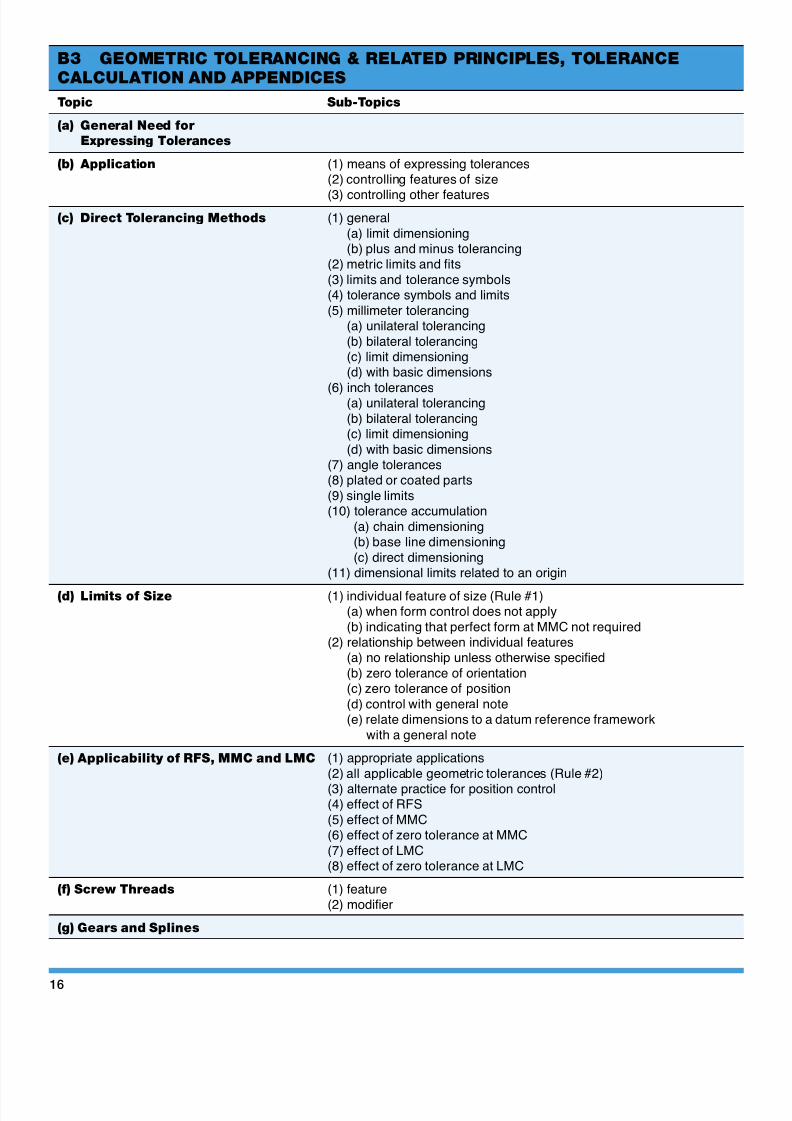
B3 GEOMETRIC TOLERANCING & RELATED PRINCIPLES, TOLERANCE
CALCULATION AND APPENDICES
Topic Sub-Topics
(a) General Need for
Expressing Tolerances
(b) Application (1) means of expressing tolerances(2) controlling features of size
(3) controlling other features
(c) Direct Tolerancing Methods (1) general
(a) limit dimensioning(b) plus and minus tolerancing
(2) metric limits and fits
(3) limits and tolerance symbols(4) tolerance symbols and limits
(5) millimeter tolerancing(a) unilateral tolerancing
(b) bilateral tolerancing(c) limit dimensioning(d) with basic dimensions
(6) inch tolerances(a) unilateral tolerancing
(b) bilateral tolerancing(c) limit dimensioning
(d) with basic dimensions(7) angle tolerances(8) plated or coated parts
(9) single limits(10) tolerance accumulation
(a) chain dimensioning(b) base line dimensioning
(c) direct dimensioning(11) dimensional limits related to an origin
(d) Limits of Size (1) individual feature of size (Rule #1)(a) when form control does not apply
(b) indicating that perfect form at MMC not required(2) relationship between individual features
(a) no relationship unless otherwise specified
(b) zero tolerance of orientation(c) zero tolerance of position
(d) control with general note(e) relate dimensions to a datum reference framework
with a general note
(e) Applicability of RFS, MMC and LMC (1) appropriate applications
(2) all applicable geometric tolerances (Rule #2)
(3) alternate practice for position control(4) effect of RFS
(5) effect of MMC(6) effect of zero tolerance at MMC
(7) effect of LMC(8) effect of zero tolerance at LMC
(f) Screw Threads (1) feature(2) modifier
(g) Gears and Splines

8/7/2019 ASME Geometric Dimensioning
http://slidepdf.com/reader/full/asme-geometric-dimensioning 17/19
17
B3 GEOMETRIC TOLERANCING & RELATED PRINCIPLES, TOLERANCE
CALCULATION AND APPENDICES (continued)
Topic Sub-Topics
(h) Virtual/Resultant Condition (1) determining the appropriateness of MMC and LMC(2) virtual condition determination(3) resultant condition determination(4) datum features at virtual condition(5) calculating inner and outer locus
(i) Angular Surfaces
(j) Conical Tapers
(k) Flat Tapers
(l) Radius
(m) Statistical Tolerancing (1) application to assemblies(2) identification
(n) Tolerances of Location (1) utilization of modifiers(a) effects of RFS (implied)(b) effects of MMC(c) effects of LMC
(2) displacement allowed by datum features at MMC
(3) calculating positional tolerance(4) zero positional tolerance at MMC(5) simultaneous requirements(6) separate requirements(7) projected tolerance zone(8) nonparallel holes(9) counterbored holes(10) closer control at one end of a feature(11) bidirectional positional tolerancing(12) noncircular features(13) coaxial controls(14) concentricity(15) symmetry
(o) Form (1) straightness(a) surface(b) axis(c) center plane(d) applied on a unit basis
(2) flatness(a) surface(b) applied on a unit basis
(3) circularity(4) cylindricity
(p) Profile (1) profile of a line(2) profile of a surface(3) coplanarity(4) for plane surfaces
(5) on conical features
(q) Orientation Tolerances (1) angularity(a) of a surface(b) applied to features of size
(2) parallelism(a) of a surface(b) applied to features of size
(3) perpendicularity(a) of a surface(b) applied to features of size
(r) Runout Tolerances (1) circular(2) total

8/7/2019 ASME Geometric Dimensioning
http://slidepdf.com/reader/full/asme-geometric-dimensioning 18/19
18
B3 GEOMETRIC TOLERANCING & RELATED PRINCIPLES, TOLERANCE
CALCULATION AND APPENDICES (continued)
Topic Sub-Topics
(s) Y14.5 Appendices (1) Appendix A - Principal Changes and Improvements
(a) Figures(b) Scope, definitions and general dimensioning
(c) General tolerancing and related principles(d) Symbology
(e) Datum referencing(f) Tolerances of location
(g) Tolerances of form, profile, orientation and runout(h) Principal changes and improvements(I) Formulas for positional tolerancing
(j) Form, proportion and comparison of symbols(k) Former practices
(l) Decision diagrams for geometric control(2) Appendix B - Formulas for Positional Tolerancing
(a) General(b) Formula symbols(c) Floating fastener case
(d) Fixed fastener case(e) Provision for out-of-squareness when projected
tolerance zone is not used(f) Coaxial features
(g) Limits and fits(3) Appendix C - Form, Proportion, and Comparison of Symbols
(a) General
(b) Form and proportion(c) Comparison
(4) Appendix D - Former Practices(a) General
(b) Definition for feature of size(c) Applicability of RFS, MMC, and LMC
(d) Tangent Radii(e) Datum feature special(f) Projected tolerance zone
(5) Appendix E - Decision Diagrams for Geometric Control(a) Purpose
(b) Functional requirements(c) Reference to standard(d) Geometric controls
(e) Choosing other controls(f) Use of modifiers
(g) Datums(1) Datum modifiers
(2) Multiple datums

8/7/2019 ASME Geometric Dimensioning
http://slidepdf.com/reader/full/asme-geometric-dimensioning 19/19
B4 APPLICATION OF MODIFIERS IN FEATURE CONTROL FRAMES
Topic Sub-Topics
(a) Types of Modifiers (1) Regardless of Feature Size (RFS)(2) Maximum Material Condition (MMC)
(3) Least Material Condition (LMC)
(b) Application (1) to the toleranced feature
(2) to datums
(3) when applicable(a) to geometric tolerances(b) to datums
(4) zero tolerance at MMC(5) results of datum features modified
(a) RFS (implied)
(b) MMC(c) LMC
(6) results of pattern of features modified(a) RFS (implied)
(b) MMC(c) LMC
(7) simultaneous requirements
B5 COMPOSITE TOLERANCING
Topic Sub-Topics
(a) Location of a Pattern of Features (1) location of a pattern of features
(2) interrelationship of individual features within a pattern(3) multiple patterns of features; separate requirements
(b) Composite profile tolerancing
(c) Part Verification Methods (1) functional gaging
(2) graphical analysis(3) mathematical analysis
(d) Application of Composite
Positional Tolerancing versus
Two Single-Segment
Tolerancing