as/nzs 3000: what has changed? - electrical connection · 16 electrical connection summer 2018...
TRANSCRIPT

1 6 ELEC TRICAL CONNEC TION Summer 2018
AS/NZS 3000: WHAT HAS CHANGED?
We live in a world of constant change, most of which is incremental and improves
existing methods or work practices.This also involves keeping up with
changes in product design and people’s lifestyles.
However, sometimes changes occur that are more disruptive and not as readily accepted.
The Wiring Rules have mirrored change since they were introduced through an act of parliament and published in 1931. Since then, the prescriptive ‘how to’ model fi rst developed by a 60-person drafting committee has been regularly fi ne-tuned as electrotechnology and lifestyle changes required.
As the year 2000 was approaching, there was opinion in the industry that the prescriptive model was too restrictive and stifl ed industry innovation.
So, when the development of the fi rst combined Australian and New Zealand Standard was proposed there was a desire for a more outcome-based Standard.
The result – the AS/NZS 3000:2000 edition – proved to be one of those more disruptive changes that was not as readily accepted as hoped.
Although there was perceived benefi t, based on substantial industry feedback,
much of the omitted prescriptive content needed to be restored.
This led to publishing AS/NZS 3000:2007 to satisfy required outcomes and prescriptive detail.
To separate the outcome-based and prescriptive parts, the Standard was split into two parts: Part 1 became outcome based and Part 2 prescriptive.
Part 1 has a single section, Section 1; Part 2 has Sections 2 to 8. Both parts are in the one document.
The considerable changes in emerging technology, electrotechnology products, work practices and lifestyle requirements have resulted in the development of AS/NZS 3000:2018, which has now been published.
To optimise its user-friendliness, users should be aware of the many ‘2018’ user-friendly aspects (the user ‘go-to’ features):* word-searchable in PDF; * layout and arrangement similar to the
2007 edition;* all substantial changes listed in the
preface (from p2 on); * table of contents with an extra level
of detail (from p9 on); * list of tables (from p20 on);* list of fi gures (from p23 on);* all substantial changes from the 2007
edition identifi ed by a red asterisk * in the margin; and,
* a ‘word or terminology’ searchable index at the back (from p578 on).If you know the topic you are looking
for is in a table or fi gure, or is described by a certain word or term, your fi rst go-to is the list of tables, list of fi gures or the index – and continues from there.
All current users are advised to archive their 2007 copy immediately and use the 2018 edition exclusively. It will be mandated in many jurisdictions by the end of December 2018 (six months from being published).
Also, you are urged to get up to speed with the changes as soon as possible, particularly new requirements (above all, those applying to your typical work types). Study these articles, the list in the preface and identify the changes by the * margin markers. You may avoid considerable rework.
It is much quicker, cheaper and less stressful to do a quick search.
The articles in this issue of Electrical Connection are set out as Sections 1 to 8 in page order. All you need do is get your AS/NZS 3000:2018 open it and start following the bouncing-ball * marker while referencing the articles in this issue. �
Acknowledgment: Standards Australia, AS/NZS 3000:2018
In the following series of articles, EL-001 committee member and industry consultant Peter Vandenheuvel runs a fi ne-tooth comb through the latest iteration of the Wiring Rules.
WIR
ING
RU
LES
2018
- I
NTR
OD
UCT
ION
BO
OKS
IN T
HIS
IMAG
E K
IND
LY P
RO
VID
ED B
Y R
OY
SAN
DS
BO
OKS
IN T
HIS
IMAG
E K
IND
LY P
RO
VID
ED B
Y R
OY
SAN
DS

w w w.electr icalconnection.com.au 1 7
2018 WIRIN
G RU
LES - INTR
O
By now I trust that all stakeholders in the electrical industry have their own genuine copy of the 2018 Wiring Rules.Unfortunately, a couple of counterfeit versions have been fl oating around. This is very
disappointing but par for the course in these times of non-conforming products.It has been a long ride since the 2007 edition. The revision, which started about seven
years ago, has been the focus of many long debates at committee level. Our fi rst meetings were about setting the scope of the revision, with all parties providing information and detail on changes and additions. Technological and work practice changes were required, and there was also a call for more clarity in the Wiring Rules.The EL-001 committee has about 35 members from all sectors of the industry. The
representation includes unions, electrical contracting and engineering associations, educators, regulators, consumer advocates, manufacturers, testing and certifi cation special-ists, and network associations in Australia and New Zealand.
About 20% of the members hail from the Land of the Long White Cloud. Thanks go to our hard-working Standards Australia project managers and to the
committee for all their intense hard work to bring this publication to completion.This was also a ‘fi rst’ in that many members took the proposals for change and clarity to the electrical industry, in essence to get crucial feedback. Much information was gleaned, helping us to fi nesse the changes as much as possible before the public comment phase.Ah, but the best laid plans… there was an unprecedented number of public comments to that draft, and I thank all of you in the industry for your input. Unfortunately, the process for adding comments was a little clumsy and many comments were not registered. However, we did receive more than 2,000 comments – huge by any
measure – and we tried our best to deal with them. Implementing more RCDs in buildings is seen as the big-ticket item, but the addition of electric vehicle charging, arc fault detection and DC installations is necessary to keep abreast of emerging technologies. The losses of power due to disaster – and potential eff ects on the aged, infi rmed or dis-abled – are important matters and we have added some detail. Further detail on discrimination and selectivity of control devices has also been provided.There are about 200 changes or additions, many providing clarity for everyday work
practices. To make things easier a red asterisk on the left side of the page indicates the changes. Rest assured that work has started on an amendment to add many of the public comments (made as the revision was under way) and feedback from the release of the 2018 edition. Most of these comments were parked during the process, as they were seen to be out of scope and needed much research.
No rest for the wicked, they say. The EL-001 committee is facing the challenge to continue providing up-to-date and technologically advanced detail for AS/NZS 3000.
- Buzz
A NOTE FROM THECOMMITTEE CHAIRMANTechnological developments and input from stakeholders make revision of the industry bible quite a task. Gary Busbridge reports on the 2018 update to AS/NZS 3000.
BO
OKS
IN T
HIS
IMAG
E K
IND
LY P
RO
VID
ED B
Y R
OY
SAN
DS
BO
OKS
IN T
HIS
IMAG
E K
IND
LY P
RO
VID
ED B
Y R
OY
SAN
DS
ALL DIAGRAMS SOURCED FROM AS/NZS 3000:2018.

1 8 ELEC TRICAL CONNEC TION Summer 2018
The foundaTion
T he importance of Part 1, Section 1 is expressed in the title of this article – it is the foundation for
the whole document, stipulating the minimum that users must achieve in order to comply.
This section may be the least used in everyday situations, but without it the Standard could not exist.
The section is crucial because: * It sets out all underlying principles
for what is required. It is what Part 2, Sections 2-8 (the detailed how-to or prescriptive ‘deemed to comply’ parts) are based on and underpins the ‘why’ for Part 2 practices to confirm compliance.
* It also provides the opportunity and mechanism for dealing with unique situations, such as the need to remedy a non-compliance that is unable to be done practically by a Part 2 solution, or the introduction and use of new or innovative technology. It provides the option to use a Part 1 solution. However, it should be noted that
the use of a Part 1 solution is (or may be) subject to the following of certain stringent processes, procedures and verification requirements in different jurisdictions.
Such solutions should never be undertaken in a cavalier manner, because they must always meet the high-level fundamental requirements.
Yet used correctly, such solutions can lead to industry and electrical installation innovation or offer the possibility for a ‘get out of jail card’ in situations where compliance with a Part 2 remedy may not be practical or possible.
Changes lisTed in The prefaCe inClude:* new and revised definitions;* removal of the mains supply
definition;* renaming direct and indirect contact
to basic and fault protection;* IP ratings;* earthing conductors to be green/
yellow;
* references to AS/NZS 3018 Electrical installations - Domestic installations re-homed to other Standards;
* requirements for alterations and repairs clarified; and,
* guidance on Part 1 solutions.
subsTanTial Changes from The 2007 ediTion in parT 1, seCTion 1 in page order inClude: * The Standard now also recognises
mitigation of foreseeable adverse effects of disruption to supply. This led to the creation of new Appendix M Reducing the impact of power supply outages focused on continuity of supply for active assisted living and homecare medical situations. This is an informative appendix providing guidance to users for reference in situations where the owner or occupier has identified the possible need to mitigate such adverse effects. (p33, p559)
* Differentiation between ‘accessible’ (capable of being reached) and ‘readily accessible’ (capable of being reached quickly and unobstructed). (p34)
* Clarification that an alteration is a modification of an installation but a repair is not. (p35)
* Introduction of arc fault detection devices (AFDDs). This led to the
creation of a new Appendix O Installation of arc fault detection devices. This is an informative appendix providing guidance to users in situations where the owner or occupier has identified the possible need to mitigate the risk of low-level arcing faults in wiring, leads and appliances (such as electric blankets) and possible resultant fires. Use of these devices is becoming more prevalent in the United States and Europe. (p35, p565)
* Definition of ‘authorised person’ is simplified as ‘selected by the person in charge of the premises’. It now excludes the terms ‘licensed electrical contractor’ or ‘electrician’ (although these can be authorised persons, where selected). (p36)
* Definition of ‘de-energised’ is added as ‘being separated from the source of supply but not necessarily isolated’. Two cross-references previously under Damp situations are moved under this new heading. (p40)
* Definition of ‘electrical installation, residential’ is added to define portions of an electrical installation associated with living units to differentiate it from non-residential portions of the same building or installation. Some examples are given. (p42)
Let’s start at the very beginning, with scope, applications and fundamental principles to set the scene.
Wir
ing
ru
les
2018
- p
arT
1, s
eCTi
on
1
Wiring Rules 2018
For more information visit www.saiglobal.com
Due to be mandated Australia wide 1 January 2019
Get switched on. Order now www.saiglobal.com/wiringrules
127662_New_Wiring_Rules_Advert_final.indd 1 9/24/18 9:46 PM

2 0 ELEC TRICAL CONNEC TION Summer 2018
* Defi nition of ‘electrical vehicle (EV)’ is added as ‘any vehicle propelled by an electric motor drawing current from rechargeable batteries’ – clarifi ed as ‘on board’ batteries. (p42)
* Defi nition of ‘energised’ as ‘connected to a source of electrical supply’ is added. (p43)
* Defi nition of ‘fi re mode’ is added as ‘a specifi c mode of operation instigated by a fi re alarm being activated within the building’. (p44)
* Defi nition of ‘functional unit’ as ‘part of a switchboard assembly’ and clarifying that ‘conductors connected but external to it’ not being part of it is added. (p45)
* Defi nition of ‘isolated’ as ‘separated from all sources and rendered incapable of being unintentionally energised’ is added. (p46)
* Defi nition of ‘lamp’ as ‘an item that emits light produced by electricity’ is added. (p46)
* Defi nition of ‘lift’ as ‘capable of raising or lowering persons but excluding hoists, dumb waiters, escalators or travelators’ is added. (p46)
* Defi nition of ‘live’ as ‘energised or subject to hazardous induced or capacitive voltages’ is added. (p47)
* Defi nition of ‘main switch’ as ‘a switch with the primary function of isolating a supply to an electrical installation’ and (subject to labelling) possibly fulfi lling regulatory requirements is added. (p47)
* Minor revision to defi nition of ‘MEN system’ to refl ect not all electrical installations are MEN systems. This is also detailed in changes to other sections. (p47)
* Defi nition of ‘neutral earthed system’ as ‘a system where the only connection between neutral and earth is at the generator or transformer has been added. (p48)
* Defi nitions ‘individual’ and ‘combined outbuildings’ are added and the diff ering requirements for earthing in each instance are added. (p48)
* Defi nition of ‘protective earth neutral (PEN)’ as ‘both functions combined in a single conductor’ is added. (p49)
* Defi nition of ‘repair’ as ‘to restore the installation to safe after damage has occurred’ is added. (p50)
* Defi nition of ‘safety service’ listing evacuation systems separately, also refl ecting a major change in lifts identifi ed as emergency lifts requiring diff erent electrical installation arrangements from lifts not so identifi ed as detailed in Sections 2-8. (p50)
* Defi nitions of ‘socket-outlets-multiple combination’ and ‘socket residual current device’ are added. (p51)
* Defi nition of ‘soft wiring’ as ‘wiring systems using installation couplers’ is added. (p51)
* Defi nition of ‘supply, alternative’ as ‘to maintain the supply in case of interruption to the normal supply’ is added to diff erentiate between alternative, normal and supplementary supplies. (p52)
* Defi nition of ‘supply, normal’ as ‘the supply the installation is supplied from under normal operation’ is added to diff erentiate between alternative, normal and supplementary supplies. (p52)
* Defi nition of ‘supply, supplementary’ as ‘a supply intended to operate in conjunction with the normal supply) is added to diff erentiate between alternative, normal and supplementary supplies. (p52)
* Defi nition of ‘wiring systems’ as ‘assemblies made up of one or more conductors, cable or busbars and parts that secure their fi xings and mechanical protection’, is added. (p54)
* Note is added to Protection by barriers and enclosures that ‘IP rating shall suit the environmental conditions and the relevant mounting position specifi ed by the manufacturer’. (p57)
* Requirement under Design of an electrical installation to ‘reduce the inconvenience in the event of a fault’ is added. See also the fi rst item in this list and new Appendix M in those situations where the owner or occupier has identifi ed the possible need to mitigate such adverse eff ects. (p66, also p33, p559)
* Requirements under Selection and installation of electrical equipment are changed, including subheading Essential requirements (renamed General) item (c) being modifi ed to also require compliance with this Standard. Requirements
under Installation work practices include additional items (f) adding further detail for wiring conductor identifi cation, (i) dealing with breathers for condensation issues and ( j) electrical equipment to be installed in a manner that maintains IP ratings. This being brought about at least in part due to manufacturer IP ratings often being compromised due to incorrect mounting and drilling for cable entry or mounting. (p68-69)
* Note 2 is added under Verifi cation (inspection and testing) to draw attention to Appendix K for guidance on switchboard inspection and verifi cation. (p70, p545)
* Text under Compliance with the requirements of other Standards is changed from a reference to domestic installations and AS/NZS3018 to now referring to Cl 7.8 and Appendix A for Standards applicable to specifi c electrical installations. (p71, p430)
* Text in Alterations and repairs is changed with deletion of ‘alterations’ from both the previous 2007 edition clause title and the text. A sub-heading Alterations has been added. The fi rst two paragraphs are replaced with ‘alterations to electrical installations shall comply with all relevant provisions of this Standard’. Also, the sentence dealing with repairs has been re-homed under its own sub-heading in this clause and a reference made to Appendix I for current ratings of imperial cables. (p71, p540)
* Sentence is added under Acknowledgement by the owner or operator (of a Part 1 solution) requiring that ‘a copy of the design documentation shall be retained at site’. (p72)
* New clause is added under Documentation (by the designer) where a Part 1 solution has been adopted – to place a permanent warning to that eff ect on the main switchboard and on all of the distribution switchboards that are part of the Part 1 solution. (p73) �
-Peter Vandenheuvel
WIR
ING
RU
LES
2018
- P
ART
1, S
ECTI
ON
1
It’s easy to switch & save on Tool & Public Liability Cover
FREE multiple quotes online in minutesCompare
your business & receive your documents instantlyInsure
yourself time and money, backed by our Price Promise Save
*$25 discount cannot be used in conjunction with any other offer. This information is general advice only and doesn’t take into consideration your particular objectives, financial situation or needs. Before making a decision please consider the relevant Policy Wording. BizCover™ Pty Ltd (ABN 68 127 707 975; AFSL 501769). © 2018 BizCover. BC1087
Ready to compare? bizcover.com.au 1300 866 744
Use code ECM25to get
$25 off *

WIRIN
G RU
LES 2018 - PART 2
PART 2: CURRENT CONCERNS
E lectrical contractors must deal with fault currents, arc fault currents, over currents, nominal
currents, over voltage, under voltage, nominal voltage, phase voltage and more.
All are diff erent and all (plus more not listed here) are crucial in making sure that the installations you design and complete will ‘meet code’, as the Americans would say.
This is the section that describes how all the key distribution elements must come together to ensure that the installation is safe and only those parts of it that are affected are turned off when an abnormal situation arises.
As noted: Part 1, Section 1 deals with all the fundamentals and their underlying principles. Part 2, Sections 2-8 contain the comprehensive how-to
that turns the statements in Part 1 into detailed complying instructions.
Part 2 is the ‘deemed to comply’ go-to part of the Standard. Follow it to the letter and you cannot go wrong. It is a guarantee to the user that if all the relevant clauses of Sections 2-8 are followed correctly, the works will comply.
Just as users of Part 1 of this Standard can comply without reference to Part 2 (well, theoretically at least), they can also do fully complying work using only Part 2.
So, what’s the major diff erence between using a Part 1 or Part 2 solution?
In a nutshell – the ease! Using only a Part 1 solution, users must demonstrate to the regulator or inspector, in great detail, how each and every part of the work complies, for
every part of the entire installation. On the other hand, when using only
Part 2, all that is needed is to verify that it meets the Part 2 requirements already defi ned – then the certifi cate of compliance is signed.
So, do you pick the easy way or the diffi cult way? The choice is up to the user but there is much to be gained by using Part 2 solutions wherever possible.
So why is there no Section 1 in Part 2? Well, a decision was made when the Part 1 and Part 2 arrangement was introduced.
This allowed the layout and numbering of the preceding 2000 edition to remain. It also prevented any confusion due to having two elements named Section 1. �
-Peter Vandenheuvel
How to handle more volts and amps than you can poke a proverbial stick at.
www.electricalconnection.com.au

2 2 ELEC TRICAL CONNEC TION Summer 2018
GET INTO GEAR
Let’s look at the overall power distribution architecture of an installation, including
required functions and features, all under the Section 2 heading General arrangement, control and protection.
This section deals mainly with power distribution. It focuses on:* control and isolation for
maintenance, testing, fault detection and repair;
* automatic disconnection of supply for over current, fault and earth leakage currents;
* protection against over-voltage and under-voltage conditions;
* suitable arrangements for switchgear and control gear groupings, locations and access;
* controlling and protecting reliability of other parts of the installation in case of faults; and,
* verifying that switchgear and control gear installation is to manufacturer instructions.Electricity distribution in all
installations has to be arranged, installed and controlled.
It involves controlling voltages and currents that can be a shock hazard and generate considerable operating temperatures.
These hazards increase as currents and voltages get higher, especially in switchboards or environments that are already at increased temperatures. Poorly selected or installed switches, circuit breakers and other current-carrying devices can result in harmful and destructive failure, and a much-reduced service life.
This makes emphasis on careful selection and reference to manufacturers’ instructions crucial to an installation’s performance, as most equipment has quite diff erent ratings in diff erent environments. Switchgear and control gear can even be destroyed if improperly used.
For instance, the rating for a piece of equipment in ‘free air’ can be much higher than when it is in a small compartment – or if surrounded by items also generating heat.
This is refl ected in some of the changes in this section and in the new Appendix K Switchboard requirement summary.
CHANGES LISTED IN THE ‘PREFACE’ INCLUDE:* adding switchgear operating
characteristics;* origin of sub-mains identifi cation;* operation of main switch details;
* position and alternative positions of overload device clarifi cation;
* expansion of discrimination requirements;
* enhancement of switchboard arcing fault protection;
* additional and revised RCD requirements;
* clearances around switchboards clarifi ed (and increased);
* guidance on the use of low-current arc fault detection devices;
* enhancement of requirements for 800A and over switchboards; and,
* clarifi cation on rising mains and other tee-off s.
SUBSTANTIAL CHANGES FROM THE 2007 EDITION IN PART 2 SECTION 2 INCLUDE: * New item (f) under Selection and
installation placing more emphasis on compliance with additional requirements in manufacturer instructions for diff erent ratings in diff erent installed environments. Refer also above. (p75)
* A note is added under Arrangement of electrical installation (d) drawing attention to the need to increase reliability of supply as further detailed in new Appendix M. (p76, p559)
Here are the minimum requirements for selecting and installing switchgear and control gear.
WIR
ING
RU
LES
2018
- P
ART
2, S
ECTI
ON
2
Iconic Styl is the newest set of skins from Clipsal to complement the Iconic range of electrical accessories. There are three changeable skin options, with more to come.
Iconic’s new skin design simply clips onto standard Iconic grids, which means you only need to carry one base range of mechs and grids, and mix-and-match skin options to suit your customers’ preferences. It’s simple efficiency that’s sure to turn heads in any new build or renovation.
clipsal.com/iconicstyl

2 4 ELEC TRICAL CONNEC TION Summer 2018
* New heading Origin of sub-mains and final sub-circuits requiring every sub-main and sub-circuit to commence at the main switchboard or a distribution board and for all the ‘live’ conductors to be connected at one switchboard’ is inserted and ‘common neutral’ renumbered. (p76)
* New heading Electric vehicle charging circuits is added referencing Appendix P and special NZ requirements. (p77)
* The heading now Common control systems (was Common requirements), General is elevated to a sub-section heading now covering new sub-section heading All systems. The previous headings are renumbered to follow. A new item (d) adds that the precautions now also include short-circuiting and earthing as supplementary measures. The word ‘poles’ under Direct current systems is changed to ‘conductors’. (p80-81)
* Under Devices for isolation – general the word ‘supply’ between ‘active’ and ‘conductors’ is deleted to now include all active conductors, not just the active supply conductors. Also, the word ‘shall’ has been moved to each of items (a) to (f) as the opening word. So, there is no material change apart from emphasising that each (a) to (f) must be complied with. (p82)
* New sub-heading Introduction is slotted in under ‘main switches’ above the otherwise unchanged wording below. The later sub-headings are renumbered to suit. Also, the ‘exception’ under sub-heading General dealing with main switches for alternative or supplementary supplies is reworded and the (a) to (g) numbering is now 1 to 7. (p83-84)
* Word ‘operation’ is added to ‘location’ for the heading to now read Operation and location. A new note (b) dealing with main switch operating handles and controls requiring manual operation and excluding electronic touch screens for main switch operation is included with the remaining clauses renumbered to suit. A new item (e) has been added detailing labelling requirements for any supplementary
or alternative supply to identify the energy source. Under Remote control new item (iii) preventing overriding or bypassing by PLC or similar and new item (d) for additional requirements where touch screens or PLCs, etc, are used in conjunction with a main switch are added. (p84-86)
* Cross-reference list under Appliances and accessories now includes (i) ‘gas appliances and accessories’ and (k) ‘lifts’ with the remainder re-indexed to suit. (p88)
* Under Emergency switching including emergency stopping the paragraph mandating an isolating device where there is a risk of shock is reworded but does not appear to change the intent. (p88)
* Text under Emergency switching devices has slight rewording of (v) for manual reset prior to starting but no apparent change of intent. (p89)
* Text under Fault protection in (b) has added compliance cross-reference to cl 5.7. (p92)
* Text under Protection against over current has a new sub-heading General requirements with renumbering of the other sub-headings to suit. Also, a note at the end of that clause dealing with reduction in current-carrying capacity numbered as Note 1 and reworded, with Note 2 referencing Appendix I (ratings of imperial cables) added. (p94, p540)
* Text under Consumer mains (b) and (c) now does not refer to note (6) and text is added after (c) that this arrangement is regarded as unprotected consumer mains with a clarification note for unprotected consumer mains and cross-referencing added. A new Figure 2.1 follows. (p94, p95)
* Note under Sub-mains and final sub-circuits – general arrangements is changed to now refer to 2.2 (A) and 2.2 (B). (p96)
* The exception under Devices for protection against both overload and short-circuit currents is now referenced to 2.5.7.2. Note 4 regarding screw-type fuses now refers to an IEC document. (p96)
* A substantial clause Characteristics of short-circuit protective devices has been moved from later in this part of the Standard but not changed. The other clauses are renumbered to suit, the figures likewise. The figures are also reworked with changes. Users should acquaint themselves with any changes. (p99-100 and Figures 2.3 to 2.10)
* The first paragraph under Protection against switchboard internal arcing fault currents – General is reworded to include the 800A and over reference previously included in the note. There has been no change of intent. (p108)
* The first paragraph under Reduction of the probability of the initiation of a switchboard internal arcing fault replaces the previous term ‘heavy current switchboards’ with the term ‘switchboards rated at 800A or greater per phase’ to clarify the 2007 edition intent. (p109)
* Figure 2.11 is included, showing which are parts of a functional unit and which are not. (p110)
* Cross-reference to 2.5.4.5 (a) is added under Protection afforded by separate devices. (p111)
* Under Co-ordination of protective devices, a paragraph is added with detail on back-up (cascading) of devices with a note to use manufacturer instructions and a reference to new Figure 2.12. The references in Note 2 are re-homed, and a Note 3 added to clarify selectivity need not apply where protective devices are in series on the same circuits, such as with UPS connected supplies. (p112-113)
* Under Safety service circuit discrimination (selectivity), ‘selectivity’ is added to the heading and the text is revised to mandate the previously more loosely worded requirements so that the original intent is reinforced. The references to figures are re-homed. (p113)
* Under General supply circuit discrimination (selectivity), ‘selectivity’ is added to the heading and the text revised to mandate the previously more loosely worded requirements. So, the original intent has now been reinforced. The use of discrimination
WIR
ING
RU
LES
2018
- p
aRt
2, S
EctI
oN
2

w w w.electr icalconnection.com.au 2 5
studies has been included in the main text; it was previously included in the notes. The reference to figures is re-homed. (p113-115)
* Under Types of RCD an additional IEC Standard, IEC 62423 (Type F and type B residual current operated circuit-breakers with and without integral overcurrent protection for household and similar uses), is added. Advice for users to consult the RCD manufacturer for type selection and Australia-only and New Zealand-only requirements are added. (p120-123)
* The heading Additional protection by residual current devices is renamed from Where additional protection is required and it has been changed substantially, including a virtual blanket requirement for RCDs on all final sub-circuits in domestic and residential situations. In addition, all RCDs must be installed at the switchboard. In non-residential installations RCDs must be provided on all socket-outlet circuits, lighting circuits, direct-connected hand-held electrical equipment and direct-connected equipment that represent an increased risk of electric shock. In non-domestic non-residential situations, for direct-connected type circuits up to 32A, the installing of 30mA RCDs should also be considered. There are exceptions and other changes, therefore users are advised to carefully study the new edition so that these requirements are fully understood. (p119-125)
* In Home care installations – Australia only RCD requirements must comply with AS/NZS 3003 and some of these may need to be Type 1 RCDs rated at 10mA. (p125-126)
* Under Alterations to installations and replacement of switchboards – Australia only RCDs must be installed where any sub-circuit is altered or socket-outlets are added. Also, where all the circuit protection on a switchboard is replaced, unless certain exemptions apply. For repairs, where a socket-outlet, luminaire or single item is replaced ‘like with like’ RCDs are not mandated. There are also some NZ-only requirements to note for NZ users. (p126-127, p130)
* Heading Protection against fire hazard due to arcing fault is new, inserted in place of Switchboards, which is renumbered to suit. Low-current arcing faults, as in faulty electric blankets and other appliances, and damaged wiring and electric cords have been identified as potential sources of house and building fires. Low-current arcing fault detection devices (AFDDs) have now become available for use in situations where the owner or occupier identifies such risk. The information here and in new Appendix O is for guidance in Australia but AFDDs are required in some situations in NZ. Further details are included. (p133-134)
* The Section 2 clause Switchboards has been renumbered as also noted above. The previous exception is numbered ‘1’ and a second exception added dealing with tee-offs and short branches where a smaller conductor may be used for up to 3m, or alternatively for those circuits to be otherwise protected. ‘Accessibility and emergency exit facilities’ (a), (b), (c) must now all be complied with and the distances/spacing around switchboards are changed as detailed in the text and the diagrams. This increases the access space to a minimum of 1m but retains access of 600mm from the open arc of switchboard doors to other open doors (i), (ii). A minimum of two emergency exits are now mandated for switchboards 800A and over or 3m
long unless there is a 3m or greater clear space in front. (p134-139)
* A new header sentence is added under Location of main switchboard requiring (a), (b) to be complied with. All references have been re-homed to reflect the numbering change of the switchboard clause, and Note 3 under (k) has been split into two to clarify the NZ requirement. (p140-143)
* The reference under Construction is re-homed. A requirement is added covering the ‘suitability’ of the environment in which the switchboard is installed. A note (1) is added referencing Appendix K Switchboard requirement summary and the other notes renumbered. A new heading Orientation and location of circuit breakers has been inserted and the second paragraph under the moved sub-heading Orientation of circuit breakers has the word ‘exception’ removed, making this a normal requirement. A new clause Location of fuses and circuit breakers setting out grouping requirements and prohibited locations is added. (p143-144, p545)
* Heading Bars or links is reduced to Bars and the word ‘link’ removed from the entire text (and will most likely fall out of use in situations applying to connection bars). The references have been re-homed. There’s a minor edit in the wording of Exceptions – ‘is not necessary’ to ‘need not apply’. (p145-147) ■
-Peter Vandenheuvel
WIRIN
G RU
LES 2018 - paRt 2, SEctIo
N 2
Advice for users to consult the RCD manufacturer for type selection and Australia-only and New Zealand-only requirements have been added.
2 6 ELEC TRICAL CONNEC TION Summer 2018
AVOIDING FUTURE SHOCK
T he new edition of the AS/NZS 3000 Electrical Installations (Wiring Rules) will come into
effect in November 2018, and Part 2, Section 2 details how electrical circuits should be arranged, controlled and protected to ensure safety.
The last update to the Wiring Rules was published in 2007. The revisions for each new update not only represent a step forward in electrical safety but also allow for the requirements of emerging products and technologies.
The 2018 edition contains several important improvements, including the requirements for residual current devices (RCDs), arc fault detection devices (AFDDs), electric vehicle charging, the arrangement of neutrals for residual current circuit breakers with over-current protection (RCBOs), and switchboard access.
Undoubtedly, the most important of these improvements are the new rules for RCDs. But, to fully understand them it is necessary to examine how the rules have changed over time.
I was involved in the original introduction of RCD requirements into the 1992 edition. As background research I analysed every record of an electric shock fatality in Australia from 1945 to 1990 that I could find to determine how many could have been prevented if RCDs had been installed.
RCDs would have made no diff erence in only two cases. In all the other instances, RCDs would have probably prevented the fatality. This made a hugely compelling case for RCDs to be mandated in the Wiring Rules.
INCREMENTAL APPROACHTwo main problems with RCDs were identified at the time.
If an RCD trips on a lighting circuit, you lose all your lights, and for circuits feeding appliances such as refrigerators and stoves, leakage current tends to cause nuisance tripping.
Mindful of these concerns, the Wiring
Rules initially recommended that RCDs should be fi tted only on socket outlets. Interestingly, research indicated that this move alone would have prevented 87% of electric shock fatalities recorded between 1945 and 1990.
The requirement for RCDs on socket circuits was included in the 1992 edition of the Wiring Rules and implemented in Australia, although New Zealand mandated RCDs for sockets only in wet areas for fear that the costs would outweigh the benefits.
This view was subsequently revised when New Zealand introduced new insulation legislation, and fi ve people died by inadvertently stapling through live circuits while fi xing aluminium foil to the underside of fl oor joists. With RCDs in place, some – or perhaps all – of those deaths could have been prevented.
Over time, the requirement for RCDs has increased in Australia and New Zealand, with a consequent dramatic reduction in the number of deaths. However, although the overall number of fatalities has dropped, electricians began to make up a disproportionally high percentage of those still occurring.
Analysis indicated that most of these ongoing deaths occurred
from drilling into wiring or making contact with exposed live parts where electrical insulation had broken off in roof spaces.
EXCEPTIONS ABATEMENTClearly, the regulations needed to tackle the changing nature of avoidable deaths.
This provided the impetus in the 2007 edition to protect all final sub-circuits in residential installations with RCDs, including lighting.
This meant that instead of locating RCDs in the socket outlet itself it was more practical to position the RCD in the switchboard, thereby protecting all downstream circuits and wiring.
To overcome the potential for losing all lighting if an RCD tripped, the Wiring Rules included a requirement for lighting to be split across at least two RCDs.
Until the latest revision, exceptions existed to prevent nuisance tripping for stationary appliances such as stoves. However, for Australia the 2018 edition stipulates that all fi nal sub-circuits up to 32A for residential installations have to be RCD protected.
The only remaining permissible residential exceptions include relatively rare equipment – such as
Dennis Galvin from Legrand Australia discusses the most important changes to Section 2.
WIR
ING
RU
LES
2018
- P
ART
2, S
ECTI
ON
2
Smart companies need smart fleets. See how our GPS fleet tracking solution can help your business. Our solutions give you total visibility in real time, so you don’t have to be somewhere to know what’s going on there.
Discover how you can see clearly, act intelligently and go with confidence at verizonconnect.com/au.

w w w.electr icalconnection.com.au 2 7
home dialysis machines – where the risk of electric shock is outweighed by the risk of a nuisance trip.
Commercial exceptions include equipment with high leakage current – such as variable-speed drives or ovens – which would trip an RCD through normal operations, or those processes requiring high-reliability circuits.
Under the 2018 Wiring Rules, New Zealand still permits exceptions for RCDs for stationary appliances.
Although this update will further reduce the number of fatalities, it will be at the expense of nuisance tripping. For instance, older equipment with heating elements that have not been specifically designed to repel moisture ingress will probably experience leakage current that will cause repeated RCD trips.
A possible compromise that was discussed was for stationary appliances to be fitted with 100mA RCDs instead of 32mA, which would eliminate most of the nuisance tripping
issues. The Electrical Regulators Association blocked this move.
This will mean that older stationary appliances will need to be replaced.
There is another interesting implication in the new rules. When an existing unprotected circuit is extended then an RCD needs to be installed for the new section, but the existing circuit does not need to be protected.
This will probably increase the demand for socket-outlet RCDs, which have become virtually obsolete since the Wiring Rules required RCDs to be located in switchboards.
AFDD on the increAseOther changes to the 2018 edition include a recommendation for AFDDs to be installed in high-risk areas to prevent arcing faults and resulting fires.
AFDDs have had a chequered history, as normal current flow in some types of equipment can be interpreted by an AFDD as an arcing
fault and cause nuisance tripping. However, the greater sophistication
of the latest signal processing technology allows for better protection with fewer nuisance-tripping issues.
Although Australia has elected to recommend AFDDs for ‘high risk ’ areas, New Zealand has taken a further step to mandate their use in schools that have accommodation, and in historic buildings.
In time, we expect AFDD requirements to expand, as has been the case for RCDs. There will always be an aspect of the Wiring Rules playing ‘catch up’ as the nature of electrical injuries shifts with the implementation of protective measures put in place.
Yet the changes to the 2018 edition will improve safety and help the industry to take positive steps towards a point at which deaths from electric fires and shock no longer occur. ■
Wirin
G rU
Les 2018 - pArt 2, sectio
n 2
www.electricalconnection.com.au

2 8 ELEC TRICAL CONNEC TION Summer 2018
A BURNING ISSUE
T he 2018 edition of the Wiring Rules covers a new type of circuit protection known as the
arc fault detection device. An AFDD automatically disconnects
supply in the event of low-level arcing faults in fi nal sub-circuit wiring. The intent is clear – to mitigate the risk of fi res being ignited by electrical arcing.
Requirements for the use of AFDDs diff er between Australia and NZ, so please refer to Clauses 2.9.6 and 2.9.7 respectively in AS/NZS 3000.
Clause 2.9 refers users to the new Appendix O for information on the installation of AFDDs.
AFDD technology has been developed over the past 20 years, fi rst fi nding application in the United States, where the National Electrical Code (equivalent to AS/NZS 3000) is heavily infl uenced by fi re protection agencies and insurers.
Eaton patented AFDDs in 1996 for the North American market and has since developed an IEC product for use elsewhere.
AFDDs have specifi c application in protecting fi nal sub-circuit wiring in electrical installations. They should not be confused with arc fl ash detectors and similar devices used in low-voltage and high-voltage electrical switchgear for protection against fi re and explosion in the event of internal arcing faults in the switchgear.
Historically, miniature over-current circuit breakers and fuses have been used for protection against fi res initiated by overheating of conductors due to overloads or short-circuits.
However, the heating eff ect of low-level arcing faults in a conductor (series arcs) or between live conductors or live conductors and protective conductors (parallel arcs) cannot be detected by these devices because it occurs at or below their rated current.
The degradation of insulation caused by carbonisation due to these low-level arcs ultimately leads to total failure of
the insulation with catastrophic results.Similarly, residual current devices
are unable to detect these faults when they do not cause an imbalance in the current-sensing device.
AFDDs employ advanced sensing techniques and algorithms to sample and analyse the waveform of the current. They discriminate between normal load current and abnormal conditions associated with arcing faults of either type.
Appendix O provides further information on the diff erences between series and parallel arcing faults in Figure O1.
When selecting and installing an AFDD, consideration must be given to:* location (i.e. after the main switch
– paragraph O4.1, and at the start of the fi nal sub-circuit it protects – paragraph O4.3); and,
* ratings (paragraph O4.2), and the product standard with which it must comply (paragraph O4.2). If the AFDD does not include integral
over-current protection, it must be installed downstream of a suitably rated over-current protection device, itself selected in accordance with the relevant product standards (paragraph O4.3bi).
The short-circuit making and breaking capacity of the AFDD must be at least capable of dealing with the prospective short-circuit current at the point of installation (paragraph O4.3bii).
Protection of the sensitive electronics in an AFDD from damage due to over-voltage should also be considered as part of the installation design (paragraph O4.4).
AFDDs should be considered for areas of highest risk, for example, socket outlets (paragraph O4.3c) or other loads where there is a risk of damage to conductors leading to arcing faults.
Installations susceptible to loss from fire may benefit from AFDDs, for example, premises with sleeping accommodation; places constructed of, or for the storage of, flammable materials; and premises where valuable items are stored, such as galleries or museums.
It may also be of benefi t to consider AFDDs for installations with ageing or deteriorating wiring. Circuits with deteriorating insulation passing through an area may also require consideration, in addition to those that terminate in an area. �
An innovative solution has been introduced to guard against fi re due to arcing. Eaton A/NZ Power Distribution business engineering manager Lindsay Lucas reports.
WIR
ING
RU
LES
2018
- P
ART
2, A
PPEN
DIX
O
PerfectPlay Easily manage Sportfield lighting through tablet, panel or smartphone
• Reduce costs
• Improve operational efficiency
• Improve the quality of the light on your pitch
• Easily control and adjust light settings
• Meet each sports’ light regulations
• Limit light pollution
Advantages of PerfectPlay
Contact the Philips Lighting Australia Team for more details on 1300 304 404 or at www.lighting.philips.com.au
Simple control devices that anyone can operate
OptiVision LED Gen 2 ClearFlood Large

3 0 ELEC TRICAL CONNEC TION Summer 2018
CABLE PICKS
A s with the selection of equipment, there are many cabling aspects to consider that
may adversely aff ect an installation. Section 3 Selection and installation
of wiring method is the glue that binds the supply and distribution equipment in Section 2 to the ‘consumer’ devices in Section 4, so the installation architecture delivers the intended outcome.
The size of cables, where they are installed, how they are protected and how they are supported or held in place can catastrophically aff ect the cables themselves, the installation, the safety of people nearby and the ultimate life of the installation.
In order to deal with some of these issues, the Standard now includes additional requirements to protect cables from damage in places such as walls, where they are concealed and may be damaged during activities as innocent as the hanging of a luminaire, picture or shelf.
The focus on energy effi ciency and the retrofi tting of thermal insulation have prompted the extension to Australia of a previously NZ-only requirement. This covers wiring above ceilings, in walls and under fl oors to cater for – and be based on – the installation of thermal insulation.
For safety, identifi cation of the origin of any sub-mains in an installation or to outbuildings must now be noted on the distribution switchboard supplied by the sub-main.
Now that wiring enclosures above roofs for PV installations are more prevalent, some guidance is provided on not interfering with the free fl ow of rain water and on the prevention of debris being trapped.
CHANGES LISTED IN THE ‘PREFACE’ INCLUDE: * improved safety requirements for
cables passing through bulk thermal isolation;
* clarifi cation of requirements for wiring systems likely to be disturbed;
* clarifi cation of cable segregation from diff erent installations in common enclosures; and,
* segregation of cables of diff erent voltages.
SUBSTANTIAL CHANGES FROM THE 2007 EDITION IN PART 2, SECTION 3 IN PAGE ORDER INCLUDE:* Deletion of ‘presence of’ in sub-
headings for Humidity, Foreign bodies, Substances; a new sub-heading Mechanical damage replaces Impact; and, further deletion of ‘presence of’ for ‘fl ora’, ‘fauna’. There is no material change. (p153-P155)
* The new heading Thermal insulation clarifi es which AS/NZS 3806 Compliance programs ratings to apply where cables pass through insulation, as these now vary depending on the length of transit through the insulation. (p155)
* The previous NZ-only requirement dealing with domestic wiring having to be based on ratings for thermal insulation in ceilings, walls and under floors is now applicable to Australia.
* The now-applicable switchboard Standard AS/NZS 61439 (Low-voltage switchgear and controlgear assemblies - General rules) for busbars and busways is added in Note 4. Australian users should understand this requirement, as it may aff ect the selection of cable size and type. (p155-156)
* Text under Connection methods, Common requirements (e) is expanded and reference made to the switchboard Standard for switchboard terminals. (p154)
* Text under Identifi cation and Exception on there being no restriction on cable sheath colour has been moved up from the notes below, reducing the Notes to 1 and 2 but with no other change.
* Cables with yellow, green or yellow/green sheath colour are not permitted for cables with active and neutral conductors in Australia. A reference to the switchboard Standard, AS/NZS 61439, is included.
* Note 4 under Table 3.4 is added that the only permitted colour for neutral conductors in NZ domestic installations is black. (p168)
* The heading Colour identifi cation is added and Colour identifi cation by sleeving or other means completely redrafted, including for the prohibition on using a green, yellow or green/yellow as an active or neutral conductor.
* There are additional requirements for the sleeving of earthing and bonding and existing live conductors. The exception immediately below Exceptions and special applications is changed to re-home references and add the reference to Table 3.4.
* A new note (d) for a multi-core cable with a green earth is included and the note (b) further down on conductors
This section deals with wiring from the incoming supply point to the fi nal sub-circuit extremities.
WIR
ING
RU
LES
2018
- P
ART
2, S
ECTI
ON
3
LED GROUP AUSTRALIA · EUROPE · ASIA · MIDDLE EAST · AFRICA
ROBUS GOTHE NEW ROBUS LOYALTY APP
Earn points and redeem them at a variety of major retailers with...
CASH OUT OPTION NOW AVAILABLE!
REGISTER NOW ATWWW.ROBUSGO.COM.AU
EARN POINTS ON ANY ROBUS PURCHASES MADE AT ANY ELECTRICAL WHOLESALERS
w w w.electr icalconnection.com.au 3 1
WIRIN
G RU
LES 2018 - PART 2, SECTIO
N 3
in fl exible cords (except for yellow) has been expanded.
* See also the note immediately above for prohibited cable sheath colour for active and neutral conductors. (p168, p169-170)
* In the Wiring systems likely to be disturbed paragraph, ‘location’ is shortened and the requirement for ‘support and protection’ added separately as a new sub-clause. It clarifi es the support requirements and contains a statement that RCDs shall not be used in lieu of mechanical protection for wiring systems likely to be disturbed.
* The fi rst paragraph under Wiring systems near building surfaces has been edited but not materially changed. The new Figure 3.3, detailing treatment of such wiring (e.g. behind a recessed or wall-mounted switchboard) is also included. (p173-174)
* Additional information on the type of mechanical protection deemed to
comply is included under protection methods (a) and (b), and there’s a note after (c) further clarifying where earthing of the protection means need not be provided. (p177)
* The grammar of the fi rst and second paragraphs under Particular installation requirements is changed but the intent remains as before. (p177-178)
* The arrangement of text under Diff erent electrical installations is changed with sub-headings Common enclosure/cable and Segregation added, replacing the previous (a) and (b) and stipulating in greater detail which cables can be in a common enclosure and which must be segregated. (p181)
* The heading Electromagnetic interference is changed to Minimisation of electromagnetic interference. There has been no change to the text. (p188)
* Under Wiring enclosures, Types (a) wording in the fi rst paragraph is changed to include the new Standard
AS/NZS 61386. There is no other change. (p189)
* The wording under Installation of wiring enclosures, General is changed. The overriding paragraph remains the same but the specifi c requirements for enclosures installed on roofi ng materials are now detailed. This is at least in part due to these installations becoming more widespread, with the wiring to PV cells, etc. There is particular focus on the requirement to avoid obstructing water draining paths and promoting debris accumulation. (p190)
* A note is added under Installation requirements, General highlighting that there are further details and fi gures later in this section. It should be noted that some of these are new, e.g. for cables installed on a sloping site or near and behind a retaining wall (Figure 3.17). There is no material change. (p196-202). �
-Peter Vandenheuvel
www.electricalconnection.com.au

3 4 ELEC TRICAL CONNEC TION Summer 2018
EQUIPPED FOR POWER
T hese are only some of the topics changed in the Selection and installation of electrical
equipment, or Section 4. This is the important business-end of the installation, where the energy so far distributed in Sections 2 and 3 is finally put to use; the purpose for which the whole installation exists in the first place.
The selection and installation of luminaires, downlights, electric vehicle charging points and other equipment items require care and attention.
There are no less than 15 pages on luminaires, most dealing with recessed downlights which are still seen as a risk area. Considerable detail, much of it from work done in NZ, has been included as guidance for electricians.
Compliance with IP ratings is also of concern. Some electricians are unaware that untested modifi cations such as drilling for a mounting bolt or cable entry can aff ect IP integrity with serious consequences. This can create considerable problems for themselves and their customers.
Lifts are now also in the spotlight. Gone are the days of ‘in case of fi re do not use lift’. Many of buildings rely on lifts to get fi re fi ghters up to the fi re and get occupants down (especially those requiring assistance).
So, there are now two types: emergency lifts and (just plain) lifts.
Because not every lift in a building needs to be an emergency lift, requirements for the two types are diff erent. Emergency lifts have to be installed in accordance with Safety services in Section 7 and lifts installed in accordance with this Section 4.
Requirements for the installation of electric vehicle charging outlets are now included.
The eff ect of these can be considerable. The electricity needed to replace the energy from 1L of petrol would aff ect the maximum demand,
cable size and socket-outlet size a great deal when based on a charging window (when the vehicle is at home) that may be only 12 hours a day.
CHANGES LISTED IN THE ‘PREFACE’ INCLUDE:* revision to fi gures for IP ratings; * revision on use of installation couplers;* inclusion of electric vehicle charging
outlets;* revision to lighting equipment and
accessories;* enhanced and updated safe
installation of recessed luminaires;* clarifi cation of the location of
accessories near cooking appliances;* isolation requirements of gas
appliances;* clarifi cation for air-conditioning and
heat pumps;* clarifi cation of protection from
weather locations;* location and requirements for electric
vehicle charging added;* isolation of individual hot water
systems added;* hazardous areas at gas-relief vents;
and,* installation of non-emergency lifts.
SUBSTANTIAL CHANGES FROM THE 2007 EDITION IN PART 2, SECTION 4 IN PAGE ORDER INCLUDE: * Under Selection and installation, the
previous note has been renumbered Note 1 with Notes 2, 3, 4 added. These reference electrical equipment installation requirements near cook tops, in damp areas and for NZ-only situations. (p213)
* Under External infl uences, the previous note is renumbered Note 1 with Notes 2 and 3 added referencing electrical installation requirements for purpose-made anti-condensation and water drains that maintain IP ratings. There is a statement that drilling a hole in the bottom will destroy the IP rating.
* Two paragraphs are added dealing with weather protection within a 30º building edge, installation requirements outside of these ‘protected areas’, and special requirements for metering enclosures and line-connector boxes. Figures are also included. (p214-215)
* For Installation wiring connected by an installation coupler(s), the requirements General are slotted in before Socket outlets. The requirements for the couplers are set out. ‘Socket-outlets’ are slotted in after ‘installation wiring connected by an installation coupler(s)’ from after ‘equipment wiring’ to before it. The text of Socket-outlets and Socket-outlets in installation wiring is considerably revised. Users should make themselves aware of the new requirements. (p220-221)
* The clause Other connection devices in the 2007 edition (p183) is deleted.
* Under Equipment wiring (e) the requirement is added that installation
Downlights are still a concern, lifts are classifi ed in two types and general equipment requirements get an update - these are the changes from Part 2, Section 4 of the new Wiring Rules.
WIR
ING
RU
LES
2018
- P
ART
2, S
ECTI
ON
4 EASYSPOOL™EASYSPOOL™ TRADIES' BEST MATE
EASYSPOOL™ is a new innovation that simplifies cable handling and installation.
Designed and engineered by Nexans Olex for Australian Electrical Contractors.
GET YOUR JOB DONE
QUICKER!
Designed to hold maximum 150kg.
CONTACT NEXANS OLEX TO FIND OUT MORECALL 1300 CABLES | www.olex.com.au
SCAN THE QR CODES TO VIEW THE LATEST VIDEOS
DOWNLOAD THE BROCHURE!https://bit.ly/2OZ5IAp
Easy to load up to 25kg per arm
Easy to manageEliminates the need to carry spools
Easy to moveTruck – jobsite – truck
Easy to reelActs as an A frame
Easy to storeMinimises space/ collapsible
Removable toolbox
3 Wheel accessory
This is theimportant
business-end of the installation.

3 6 ELEC TRICAL CONNEC TION Summer 2018
wiring passing through luminaires must not suffer damage or deterioration from luminaire UV radiation. This was at least in part brought about by use of wiring not resistant to UV through fluorescent fittings. (p222)
* Under Socket-outlets (a) a reference to AS/NZS 60864 is added and a new heading Socket-outlets – alternative pin configurations added with the requirements more clearly defined. Subject to the socket-outlets meeting all these requirements they (e.g. sockets with other-country pin configurations) can be used in any electrical installation in Australia, but not in NZ where the limitations and additional requirements set out must be complied with. (p223-224)
* A new heading Low-voltage fixed socket outlets has been added. This prohibits socket-outlets also having a combination telco, data, television, radio or similar wiring system socket-outlet. (p224)
* A new heading Socket-outlets for electric vehicle charging’ is added referencing Appendix P and setting out the NZ requirement for installation of these outlets. (p224)
* Under Location, Accessibility, a note has been added under (a) for Standards applicable to socket-outlets mounted in a floor. (p225)
* Under Lighting equipment and accessories a new heading Lamp holders, including lamp holders incorporated in a luminaire is added. There is a change to Figure 4.9 and an exception to the requirement for the warning sign where specifically identified luminaires are exclusively installed. The previous heading Installation precautions has been renamed Installation and precautions changed to requirements. The requirements are substantially changed. (p232-243)
* The previous heading Smoke and fire detectors is changed to Smoke alarms and the term Fire detectors deleted from the text. (p243)
* Under Cooking appliances, Switching devices the text is considerably changed and Australia-only and NZ-only clauses added. A new figure is also included. (p243-245)
* Under Water heaters a requirement for an independent isolation switch for each heater adjacent – but not on – the heater is now included. (p246)
* Under Electricity converters, Selection and installation item (d) is revised to show the current Standards series that applies. (p250)
* Under Overcurrent protection, General, the text is changed with no real ramifications except that RCDs are now under their own heading. There is a more detailed explanation and a requirement for the correct type to suit the waveform of the converter to be selected. (p252)
* Under Gas appliances and equipment there are new Australia-only and NZ-only requirements for the means of isolation via a plug in a socket-outlet (with a separate switch if the socket-outlet is not accessible) or where an isolating switch is included. (p261)
* Under Gas cylinders containing heavier than air gases, Hot particles and surfaces requirements have been changed, Australia-only and NZ-only. Additional figures are included. (p261-264)
* A further paragraph is added under Air-conditioning and heat pump systems requiring a warning notice adjacent to the isolators for these systems if there are other points of isolation for ancillary associated devices. A second exception is added. (p264-265)
* A new heading Lifts is included. This requires lifts to comply with AS/NZS 3000. As a point of interest, users should note there are now different requirements for lifts, emergency lifts and (presumably) non-emergency or (normal) lifts. This has come about at least in part due to many buildings being too tall for evacuation without lifts. So, the old ‘in case of fire do not use lifts’ is no longer the case for many buildings. Imagine people needing assistance or in wheel-chairs faced with 20 or more flights of steep stairs. Consequently, when there is more than one lift, building designers, owners or occupiers must nominate the type. Both types are to be installed with the requirement of the National Construction Code (in Australia) or the New Zealand Building Code. In AS/NZS 3000 the emergency lifts are now treated as safety services, and the other lifts typically as any other part of the installation. (p265-266) ■
-Peter Vandenheuvel
RECESSEDLUMINAIRE
SCB SCB
SCG
HCB
HCG
SCG
IC/IC-F CLASS
NON-IC CLASS
CA CLASS
RECESSEDLUMINAIRE
RECESSEDLUMINAIRE
SCB
SCG
SCI
CG
CG
CG
CG
FIXED GUARD REQUIRED WHERE:∫ INSULATION MATERIALS ARE NOT SECURED IN POSITION;∫ LOOSE MATERIALS ARE PRESENT.
Figure 4.9: Default minimum clearances for recessed luminaires.
Dimension any lamp up to 100w
HCB- Height clearance to building element 100mm
SCB- Side clearance to building element 100mm
SCI- Side clearance to insulation 100mm
SCG- Side clearance to auxiliary equipment [control gear (CG)] 50mm
WIR
ING
RU
LES
2018
- p
aRt
2, S
EctI
oN
4
Back up power protection
Control & automation
Engineering services
Lighting & security
Power distribution & circuit protection
Power conditioning & quality
Solutions for harsh & hazardous environments
Structural solutions & wiring devices
The Eaton Experience Centre Sydney 10 Kent Road, Mascot 2020 NSW
1300 332 [email protected]
BRAND INCEPTION DATES:
1833 1874 1893 1897 1899 1906 1908 1911 1914 1934 1961 1962 1963 1967 1977 1983 1984 1989
Tel: 1300 3 EATONwww.eatoncorp.com.au
power management needs of n a century. Over the years, ertise and portfolio of products e of the world’s most respected heritage of innovation.
de unique solutions across a eep businesses on the leading
power of One Eaton.
18741833 1911 19141893 198319621961 1989198419771908190618991897 1963 19671934
BRAND INCEPTION DATES:
DNA advert 5mm bleed WHITE.indd 1 13/03/2017 10:09:48 AM
Tel: 1300 3 EATONwww.eatoncorp.com.au
power management needs of n a century. Over the years, ertise and portfolio of products e of the world’s most respected heritage of innovation.
de unique solutions across a eep businesses on the leading
power of One Eaton.
18741833 1911 19141893 198319621961 1989198419771908190618991897 1963 19671934
BRAND INCEPTION DATES:
DNA advert 5mm bleed WHITE.indd 1 13/03/2017 10:09:48 AMTel: 1300 3 EATON
www.eatoncorp.com.au
power management needs of n a century. Over the years, ertise and portfolio of products e of the world’s most respected heritage of innovation.
de unique solutions across a eep businesses on the leading
power of One Eaton.
18741833 1911 19141893 198319621961 1989198419771908190618991897 1963 19671934
BRAND INCEPTION DATES:
DNA advert 5mm bleed WHITE.indd 1 13/03/2017 10:09:48 AM
Tel: 1300 3 EATONwww.eatoncorp.com.au
power management needs of n a century. Over the years, ertise and portfolio of products e of the world’s most respected heritage of innovation.
de unique solutions across a eep businesses on the leading
power of One Eaton.
18741833 1911 19141893 198319621961 1989198419771908190618991897 1963 19671934
BRAND INCEPTION DATES:
DNA advert 5mm bleed WHITE.indd 1 13/03/2017 10:09:48 AM
Tel: 1300 3 EATONwww.eatoncorp.com.au
Eaton has been serving the power management needs of our customers for more than a century. Over the years, we have expanded our expertise and portfolio of products and services by uniting some of the world’s most respected names with Eaton’s strong heritage of innovation.
Our goal is simple; to provide unique solutions across a wide range of markets that keep businesses on the leading edge of change. That’s the power of One Eaton.
18741833 1911 19141893 198319621961 1989198419771908190618991897 1963 19671934
BRAND INCEPTION DATES:
Untitled-2 1DNA advert 5mm bleed WHITE.indd 1 13/03/2017 10:09:48 AM

3 8 ELEC TRICAL CONNEC TION Summer 2018
PULL THE PLUG ON RISK
T he style of the latest edition harks back to the way the Wiring Rules were presented 30 years ago.
At that time, the rules were very prescriptive, clearly stating what needed to be done, and how, with little scope for misinterpretation or confusion.
However, in time the language has softened along the lines of requiring an installer to make ‘a safe installation’ or provide ‘adequate protection’ without clearly defi ning either. Electricians believed that their way of doing things was ‘safe’ and ‘adequate’, but in practice there was a huge range of possible interpretations based on individual experience.
The 2018 Wiring Rules have reverted to more precise instructions, leaving less potential for an incorrect interpretation and providing a more standardised approach across the industry.
Most electricians will welcome this approach, as they will have a more certain understanding of what is required for compliance with fewer grey areas to consider. It will also mean that when electricians are working on existing electrical circuitry in future they will have a great sense of surety that the
original installer worked to the same understanding of the Wiring Rules.
A potential drawback of the more prescriptive approach is reduced fl exibility in non-standard situations. However, the style of the new Wiring Rules strikes a good balance between the clarity of requirements for meeting the code and some ‘wriggle room’ where necessary.
For instance, an engineer can sign off a proposed variation as complying if this can be demonstrated to be equal in safety to the approach described by the Standard.
OVERSEAS OUTLETSUnlike many European nations, Australia and New Zealand have been blessed with a single plug-socket system throughout the countries’ histories.
Appliances are typically sold in Australia and New Zealand with factory-fi tted plugs – a safer approach than in the UK, for example. The existence of legacy socket systems in older British properties meant that until quite recently appliances were often sold without plugs, and consumers fi tted their own.
However, one of the downsides to the ‘single socket’ scenario is that the Wiring Rules have made little provision to date for meeting the plug-socket needs of international travellers.
There had been a move to install universal sockets or multi-outlet sockets with large enough apertures to accept virtually any kind of plug pins – for hotel, hospitality and travel industry applications, but such accessories were banned because they didn’t conform to Wiring Rules requirements for the pin aperture.
Equally, it wasn’t hitherto possible to install foreign plug sockets in an Australian or New Zealand building, as these would fail to comply with the AS/NZ 3000 Standard.
Finally, the issue is resolved in the 2018 edition of the Wiring Rules, which allows the installation of UK, US, French and German outlets, provided they conform to the International Electrotechnical Commission (IEC) Standard for apertures and can accept only one type of plug.
This move is intended to allow hotels and airports to legally install socket outlets in guest or public areas. It will
Dennis Galvin from Legrand Australia reviews changes to Section 4 of AS/NZS 3000:2018 that are designed to improve safety and clarify interpretation.
WIR
ING
RU
LES
2018
- P
ART
2, S
ECTI
ON
4
Quality tools for every tradesmanBEST SELLERS!
www.weidmuller.com.auNote: All special prices valid from the 1/10/18 to 31/12/18
$69SALE
+ $6.90 GST
stripax®Automatic Stripper & Cutter• For flexible cables from 0.08mm² to 10mm²• Self-adjusting blades won’t damage cable• Stripping length up to 25mm adjustable by wire stop• Removable handle for optimised ergonomic
Order number: 9005000000
$189SALE
+ $18.90 GST
CTI 6Double-crimp profile in 1 easy step• For insulated lugs 0.5 to 6mm² (red, blue, yellow)• Release option in case of incorrect operation• Locator for exact positioning of contacts
Order number: 9006120000
PZ 6 RotoUniversal ferrule crimper with rotating dies• For ferrules with or without plastic collars• Rotatable crimp die for ferrule insertion from the side or the front• For cable sizes 0.14mm² to 6mm² in 1 crimp die• Ratchet with automatic releaser
Order number: 9014350000
$169SALE
+ $16.90 GST

w w w.electr icalconnection.com.au 3 9
provide a safe, workable solution to a problem that has plagued the industry for many years.
The new Wiring Rules also offer much clearer guidelines for recessed luminaires.
In Australia, recessed luminaires can be installed only if they meet the minimum CA90 rating, which specifies that the casing will not exceed 90°C.
Interestingly, New Zealand permits CA135 rated luminaires, designed to not exceed 135°C. It is a somewhat counter-intuitive decision, given that many of these luminaires will be installed in wood-frame buildings and the pyrolytic ignition temperature for wood is just 105°C.
Apart from this, the Section 4 chapter on recessed luminaires is more comprehensive than before. It contains more stringent requirements and more easily understood guidelines, especially with regard to installation near insulation material.
Given the number of fires caused by downlights in recent years, this guide is a timely revision.
IsolatIon Issues
The 2018 edition also introduces rules that require isolation switches on gas appliances – including gas heaters – stipulating that they be double-pole.
This addresses the hazard associated with single-pole connections where it is possible to generate a voltage between neutral and earth during switching, thereby creating the potential to ignite gas.
Although this inclusion makes sense from a safety standpoint, EL-001 committee members hope to amend it to avoid the necessity for large industrial-type switches in people’s lounge rooms.
One option is to provide a socket for the appliance, allowing it to be unplugged to obviate the need for an unwieldy switch. This isolating switch section in Section 4 is a major
amendment to the Wiring Rules, its more stringent requirements arising in direct response to numerous reported incidents, especially those involving gas fitters.
Overall, the revisions to Section 4 are well thought through and intelligently presented, providing incremental improvements to safety in several key areas, and clearer guidance.
For example, the designation of IP zones for the outside installation of electrical equipment is much clearer than before. The Wiring Rules now state that if a line is drawn down at an angle of 30° from the eaves – or any similar balcony or overhang – then above the point where the line intersects the wall, IP33 equipment can be used. Below this level IP55-rated equipment is required.
Sensible recommendations such as this will help promote best-practice installation throughout the industry and remove much of the uncertainty from safety concerns. ■
WIRIn
G Ru
les 2018 - paRt 2, sectIo
n 4
www.electricalconnection.com.au

4 0 ELEC TRICAL CONNEC TION Summer 2018
EARTH CALLING
A close reading of Section 5, Earthing arrangements and earthing conductors, should,
hopefully, dispel any misconceptions.People see a main earth connection
or an earth bonding cable connected to a pool fence or on a conductive building without any further protection and it is assumed to be somewhat benign. After all, it can (almost always) be touched without consequence.
Even in the industry some electricians don’t isolate before disconnecting an earth conductor or when temporarily separating two conductors where remaking a connection. In most cases they get away with it, but that is only because everything in the installation is sound.
However, if there is an unknown fault in the installation, disconnecting
an earth conductor can be just as dangerous as disconnecting a neutral when the circuit active is energised and there is a load (no matter how small) on the circuit.
Correct earthing is paramount to ensure that circuit protection operates properly and quickly. It is crucial for the safety of an installation and the people using it – and that makes this section as important as all the others.
Also, although most installations are still connected to an MEN system connected grid, there are many instances in which alternative earthing systems are required. Think of certain mine sites, remote installations, stand-alone grids, micro-grids and other settings. Hence there is more information on these alternative earthing systems.
CHANGES LISTED IN THE ‘PREFACE’ INCLUDE: * MEN system clarification and
accessibility of connections;* updated SELV and PELV
requirements;* expanded and clarified equipotential
bonding for showers, bathrooms pools and spas;
* earthing of conductive materials in outbuildings;
* earthing for switchboard enclosures with unprotected consumer mains;
* earthing of conductive reinforcing in outbuildings with showers or baths; and,
* earthing connection point and bonding of conductive pool structures and fittings within arm’s reach, with figures included.
SUBSTANTIAL CHANGES FROM THE 2007 EDITION IN PART 2 SECTION 5 IN PAGE ORDER INCLUDE: * A reworking of figures. (p269-270)* Additional Note 5 under Other
earthing systems to recognise additional installation systems, with other notes renumbered from (a) to (d) to 1 to 4. (p271)
* Sentence added under MEN, General, Exceptions after the note for the MEN or ME connection to be in an accessible position for disconnection and testing. (p281)
* Minor changes to Table 5.2 clarifying stainless and steel clad – with stainless steel being equally complying, and qualifying that the 20mm steel pipe must have a minimum 3mm wall thickness. (p283)
* Redrafted colour diagram is provided showing all the diff erent earthing confi gurations that can be used. (Users should remember that earthing conductors should be installed such that the earth connection to various remaining earthing conductor connections is
Earthing, which is the focus of Section 5, has a crucial but often overlooked role in what makes an electrical installation very safe or extremely dangerous.
WIR
ING
RU
LES
2018
- P
ART
2, S
ECTI
ON
5

w w w.electr icalconnection.com.au 4 1
not accidentally disconnected if one earthing connection point is disconnected. (p292)
* New terms are introduced under Particular methods of earthing, Outbuildings, for ‘individual outbuildings’ and ‘combined outbuildings’ to clarify that individual outbuildings can have an MEN instead of an earth from the source of supply and likewise for combined outbuildings. But in the combined outbuildings only one incoming supply can have an MEN connection and all the others must have their earth conductors from that MEN connection. This has also required splitting the original (a) into (a) and (b) with considerable change in test and the original (b) becoming (c). Figures 5.4 and 5.5 have been added to explain. (p293-295)
* Under Unprotected consumer mains Figures 5.6 (A), (B) and (C) are added. Also, a second sentence and note are added immediately under the heading with further detail here and with references to the figures throughout. The original notes are now also headed Exception but the intent of these has not changed. (p296-300)
* Under Arrangement, General note (f) is changed from general access floors requiring additional bonding to grid-connected inverters now requiring bonding. There is no other change. (p304)
* Requirement for bonding under Showers and bathrooms for combined outbuildings is further detailed in two new paragraphs. The ending of Note 3 has is changed to ‘sufficient’ from the previous ‘satisfactory where bonding is required at more than one location’. Note 4 is modified to clarify that this is not a requirement in existing buildings, and also with more emphasis placed on doing it wherever practicable. (p307)
* Order of headings under Swimming pools and spas is substantially changed and considerably modified. Due to this, all cross references have been rehomed. A new figure 5.9 Examples of bonding arrangements has been added. The new order of headings is:* Bonding arrangement: the wording in (a) and (c) has
been changed but (a) and (d) remain as before. There are no changes in intent. The new Figure 5.9 is also referenced.
* Conductive pool structures: two new paragraphs and an exception are added to further clarify the requirements and Note 2 is changed to reflect other changes.
* Pool equipotential conductor connection point: is changed from ‘equipotential conductor connection point’ and the opening paragraph substantially reworded, with minor changes also to (a) and (c).
* Electrical equipment: no change apart from an example added under (b). (p309)
* Conductive fixtures and fittings: the opening paragraph is considerably expanded to reflect the changes under the Swimming pools and spas heading, previous (a) and (b) are deleted and or incorporated in new paragraphs 1 and 2, and new exceptions 1 and 2. (p309-310) ■
-Peter Vandenheuvel
MAIN EARTHINGCONDUCTOR
MAIN EARTH BAR
NEUTRAL BAR
MAIN NEUTRALCONDUCTOR
SERVICENEUTRAL
TO INSTALLATION MAINSWITCH OR SWITCHES
SERVICEPROTECTIVEDEVICE
Unprotected single insulatedconsumers mains ina wiring enclosure.
MEN link, ≥ size of the main earthing conductor.Clause 5.3.5.2Exception 2
≥ size as themain neutral conductor.Clause 5.5.3.5 (a)
CONDUCTIVE SWITCHBOARD ENCLOSURE
ENERGY METERINGARRANGEMENT
Conductive fence withinarm’s reach of pool edge,Clause 5.6.2.6.5
Earth bond connected to earth bar of switchboard or earth terminals of supply circuit.Clause 5.6.2.6.1
Class 1 pool pump,Clause 5.6.2.6.4
Conductive ladder and diving board,Clause 5.6.2.6.5
Conductive lamp posts within arm’s reach of pool edge,Clause 5.6.2.64
Bonding to reinforcing mesh,Clause 5.6.2.6.2
POOL REINFORCING MESH
ARM’S REACH1.25M
Bonding connection point,Clause 5.6.2.6.3
Figure 5.6(A): Earthing arrangement for conductive switchboard enclosures associated with unprotected consumer mains [clause 5.5.3.5(a)].
Figure 5.9: Example of bonding arrangement for pools and spas.
WIRIN
G RU
LES 2018 - paRt 2, SEctIo
N 5
4 2 ELEC TRICAL CONNEC TION Summer 2018
Wet and Wild
The safe bringing together of power and water continues to be a challenge but hopefully the
changes to Section 6 Damp situations will throw more light on how best to manage this.
There are often obvious signs of something amiss, like a tingle from a tap in the shower, bath or laundry. And if there is one piece of advice worth heeding and passing on to the occupiers in such situation, it is: “Get out from wherever you are, ring the electricity distributor and do not go back until it is made safe.”
Some anecdotal information suggests that up to 25% of reported shock incidents involve a problem with the neutral connection to the premises putting the person in harm’s way when they become a part of the return path.
This section is very important where there is a water container, flowing water or a damp situation plus conductive parts – earthed or just connected to the mass of earth – that are both within arm’s reach.
Changes listed in the ‘prefaCe’ inClude: * additional content for water
containers not normally entered by people;
* installation requirements for deluge showers;
* Zone 1 areas for different shower head locations;
* reduction of water containers to 40L (max);
* zoning for hinged doors on showers;* increase of spa pools to 680L;* prohibition of generating systems
and inverters in classified zones; and,
* exclusion zones for location of pools and spas from creating a hazardous zone for electricity distributor equipment.
substantial Changes from the 2007 edition in part 2, seCtion 6 in page order inClude: * Under Baths, showers and other
fixed water containers, Scope, the final words ‘with earth potential’ are changed to ‘with the general mass of earth’. The sentence before ‘notes’ is reworded and cross-referenced but not otherwise materially changed. (p317)
* Under ‘(c) Zone 1’ for a shower, item (ii) is clarified for a fixed wall shower to allow the 1.2 dimension to be reduced where a barrier is installed, providing this is at least 1.8m or as high as the wall connection. Item (iii) has been clarified for a fixed ceiling shower with differing arrangement as well as Australian and NZ requirements. An exception is also added. The last two previous exceptions have been changed and these now apply to Australia and NZ respectively. A further item (vi) dealing with the height of the fixed plumbing connection that was previously in the note is added, with examples of barriers detailed in the remaining note. (p318)
* Under Other fixed water containers (b) the maximum volume of each water container is reduced to 40L from 45L, as it is understood this volume is the most used. Likewise, for (c) the volume is also reduced to 40L. There are no other changes. (p319)
* New heading Electrical generation systems is added to specifically exclude installation of generators, generating systems, inverters and batteries in any classified zone. A separate line to this effect is included in Table 6.1. (p322-323)
* New figures are slotted in as Figure 6.5 and Figure 6.6 to show a shower with a fixed ceiling plumbing connection (e.g. rain shower). Likewise Figure 6.8, showing a
shower with a hinged door and 6.11 for a ceiling fixed shower with a barrier. Some existing figures have also been adjusted. (p327-328, p330, p333)
* Previous figures showing water containers have been renamed and their volume reduced to 40L per container. (p335-336)
* Maximum capacity under Spa pools or tubs, General, is increased from 500L to 680L. (p337)
* First paragraph under Luminaires, appliances and other electrical equipment now includes the specific exclusions and cross-referencing for classified zones. (p340)
* New heading Electricity generating systems has been added to prohibit installation of electricity generating systems, generator sets, power systems, inverters and batteries in any classified zone. This is included in an additional line in Tables 6.2 and 6.3. (p342, p351 and p344, p352)
* A new heading Electricity distributor’s electrical equipment prohibits pools and spas in areas where this would mean distributor electrical equipment, pits and cabinets would then end up being in a classified zone. This has been included in an additional line in Table 6.2 and 6.3. This has arisen from situations where pools and the like have been installed almost on top of pre-existing distributor equipment. (p342, p352 and p344, p352)
* A new Table 6.3 (as referenced above) for ‘selection and installation of electrical equipment for fountains and water features’ is included. (p352)
* Under Saunas the second paragraph is split and a cross-reference added, but there is no change of intent. (p354) ■
-Peter Vandenheuvel
Electricity and water make poor bedfellows, but they often have to be near each other to meet architectural and lifestyle needs. These are the changes from Section 6.
Wir
ing
ru
les
2018
- p
art
2, s
eCti
on
6
c
COMMERCIAL
Takeko
Stylish, energy efficient options to suit any space.
Sydney 34 -36 Adderley St East, Lidcombe, 2141 P +612 9699 7255
Melbourne 8/621 Whitehorse Rd, Mitcham, 3132 P +613 8415 0277
Brisbane 7/19 Lensworth St, Coopers Plains, 4108 P +617 3216 9039
Adelaide 2/34 Bennet Ave, Melrose Park, 5039 P +618 8374 0553
Perth 3/11 Howe St, Osborne Park, 6017 P +618 9444 9653
INTRODUCING THE
NEW FAN COLLECTION FROM BEACON LIGHTING COMMERCIAL
View the range and get a quote at www.beaconlightingcommercial.com.au
Shoalhaven
Whitehaven
Banksia
8183B Commercial Electrical /Building Connection 11.9.18.indd 1 13/9/18 1:52 pm

4 4 ELEC TRICAL CONNEC TION Summer 2018
A bit speciAl
E lectrical installations deemed Special electrical installations are covered in Section 7.
The categories include: safety services, generating systems, protection by electrical separation, extra-low voltage and high voltage, and explosive hazards.
It should be noted where this section does not specify a requirement, the relevant requirements of the other sections of AS/NZS 3000 apply (and these may also call for compliance with other Standards).
Emergency lifts, the only lifts now deemed as safety services, figure quite prominently in this section and in the changes.
This is one of the sections with a large number of changes, although this may not be reflected in the changes listed in the preface as summarised immediately below. For this reason, users would be well advised to come up to speed with this section.
chAnges listed in the ‘prefAce’ include:* complete restructuring of safety
services and their requirements;* clarifications for the installation of
electricity generating systems;* addition of electric vehicle charging
systems; and,* revision of specific electrical
installation requirements.
substAntiAl chAnges from the 2007 edition in section 7, in pAge order, include: * Under Safety services the heading
Scope is changed to Scope and general, the existing heading Scope is included as a sub-heading and the first paragraph previously under General is now directly under Scope. (p363)
* Subheading General now heads up the rest of the clause. The various exceptions are listed 1 to 6 below the heading for situations that need not comply with this section. The exceptions include, but are not limited
to, escalators, moving walkways, single-resident lifts, lifts not defined as emergency lifts, jacking pumps, fire alarms with battery back-up and smoke alarms in private residences. (p363)
* New notes are listed for cross-reference to AS/NZS 3009 for power supplies in hospitals. Safety systems in part replaces the previous edition’s Emergency systems. This also includes Emergency equipment in the National Construction Code and NZ Building Code. Some information on ‘fire-resistance levels’ (FRL) is included. (p363-364)
* The safety services part of this section has had a complete make-over to make it more easily and logically searched, read, understood and followed. Because it has undergone such drastic change from the previous edition, users are urged to become acquainted with these requirements urgently. (p363-384)
* Supply systems notes the additional requirements for wiring safety services – these cannot be used for other purposes. Also, when safety services are required under emergency conditions it may be necessary to automatically disconnect (i.e. load-shed) non-essential equipment.
* New Figure 7.1 is included for wiring system classification of lift circuits (author’s note: for ‘emergency lifts’, as these are the lifts for safety services). Details on ‘wiring systems - for safety services – (mains, sub-mains, main switchboard and supplies to
outbuildings)’ WS classifications are detailed and required to comply with AS/NZS 3013. ‘Alternative supply systems’ are also included. (p364-367)
* Main switchboard and switchgear requires a safety service to be controlled by a main switch separate from other main switches. Safety services must be separated by metal barriers. Conductors for safety services must be separate from other safety services and from other services. Load-break switches for isolation or circuit breakers (discriminating with others in the supply circuit) must be used. Typical arrangement line diagrams have been included. (p367, p371)
* The clause Main switches has been redrafted. There is still no limit on the number of main switches, but each must be separate from other main switches for other parts of the installation. Each must be mechanically protected, identified as a main switch in a contrasting colour and marked ‘in the event of a fire do not switch off’. (p371-373)
* Fire pumps and fire control equipment is substantially edited. These must also comply with AS/NZS 3013. It applies to booster pumps, automatic sprinkler system pumps, fire pump rooms, fire pump control equipment and pumps for fire hose reels. (p373-378)
* Fire and smoke detection equipment and fire alarm systems is substantially edited. It applies to fire and smoke detection equipment, fire
Some electrical installations have particular requirements when it comes to safety.
Wir
ing
ru
les
2018
- p
Art
2, s
ecti
on
7

w w w.electr icalconnection.com.au 4 5
WIRIN
G RU
LES 2018 - paRt 2, SEctIo
N 7
indicator panels, fire and smoke alarm systems and warning and intercom systems. (p377-378)
* Air-handling systems must comply with AS/NZS 3013. There is a cross-reference to Appendix H regarding the WS system. Segregation for cables is required. No switch is to be interposed between a main switch and downstream switchboard. (p378-379)
* Evacuation equipment must also comply with AS/NZS 3013. This must include sound systems and intercom systems to be compliant with AS 1670.4 (Fire detection, warning, control and intercom systems - System design, installation and commissioning Emergency warning and intercom systems). Emergency evacuation and lighting requirements are provided for in the National Construction Code or NZ Building Code. (p379-380)
* Emergency lifts are safety services in Australia. Compliance with AS 1735 is not a requirement of AS/NZS 3000 but regulatory authorities may require compliance with that Standard or may have additional requirements. In NZ, lifts required for fire-fighting or other emergency purposes are safety services. Emergency lifts must also comply with AS/NZS 3013 (Electrical installations - Classification of the fire and mechanical performance of wiring system elements). In addition, no switch is to be interposed between a lift main switch and the downstream switchboard. (p380-382)
* Emergency motor-room less lifts are lifts that do not have a lift motor room. Where these are installed for evacuation, fire-brigade activities and emergency use they must comply with this requirement. (p382-384)
* Item (b) under Electricity generation systems, General, Stand-alone system is redrafted and now lists typical systems in (i) to (iii). Item (c) has been renamed Inverter system. Its intent has not changed. (p384)
* The new heading Basic protection and fault protection is added under Control, requiring provision to be made for all basic and fault protection (including MEN) connections to remain intact when supply from the output of
the generator is available. (p386)* A requirement is added directly
under Isolation, General that an inverter or regenerative supply source shall not be connected downstream of the generating set changeover device. An exception is also included. (p385-386)
* The sentence immediately under Over-current protection, Electricity generation system protection, is expanded to require this to be in line with applicable Australian and NZ Standards for the particular generation system being installed and where the Standard does not specify that the further requirements detailed thereunder apply. The exception below this in the previous edition is now to apply only to a new (a), and is immediately below that item. The paragraph that was below the exception is now the new item (a). The sentence that was below the paragraph – was item (a) – is now (b) and is reworded with additional detail but its intent is not changed. (p387)
* There are changes under Connection to electrical installation, Alternative supplies, General. The previous (b) has now become (a) but the text is not changed. The previous (a) is now (b) and the previous text and note are now a single paragraph with no material change. The note that was under the previous (b) has been added as a further paragraph (not a note) under the new (b), so changing what it applies to. The note (c) remains. The exception is also changed to be in two parts. The first part ‘1’ is now for Australia only, with the only change being that (i) to (iv) are now bullet points. The second part ‘2’ is a new requirement for NZ only dealing with connections without an N-E link when the installation is operating from an alternative supply. (p389)
* There are minor changes under Connection to electrical installation, Alternative supplies, Switching, which is rewritten to include a previous note and the references are rehomed. There is no change of intent. (p390)
* Figures 7.3 to 7.6 have been renumbered and redrafted in colour,
but no intentional change has been introduced. (p391-394)
* The previous ‘notes’ to (the 2007 edition) Figure 7.5 that were between Grid-connected inverter systems and Stand-alone power systems (previously p314) are not included. (p395)
* The new heading Variable speed drive (VSD) EMI filters requires (where these are used) that they must not reference the frame of the system, and optimally only one filter should be used on an isolated supply with multiple VSDs. It also notes that these filters when referenced to the frame may cause harmful capacitive coupled currents. (p399)
* Note 2 in Figure 7.8 dealing with separated (isolated) supplies is reworded to include that circuit breakers may operate in all live conductors or HRC fuses in all active conductors. (p401)
* Reference Standards under Standards containing additional requirements that are changed in this edition include those for, high-voltage installations, generating sets, inverters, low-voltage switch and control gear assemblies, stand-alone power systems, PV arrays, secondary battery systems, mobile medical facilities, floor and ceiling heating, explosive atmospheres and hazardous areas. Other text may also be changed, and users are urged to check. (p411-412)
* Reference standards under Standards containing guidance that are changed in this edition include those for emergency supplies in hospitals, lightning protection, UPS systems, semi-conductor power converters, rotating electrical machines, periodic verification and verification guidelines. Other text may also be changed, and users are urged to check. (p412-413)
* The new heading Supplies for electric vehicles (NZ only) has considerable detail and also references Appendices P and C. NZ users are urged to become familiar with these requirements. (p413-415) ■
-Peter Vandenheuvel

4 6 ELEC TRICAL CONNEC TION Summer 2018
VERILY, IT’S CRUCIAL
Verifi cation, the title of Section 8, certainly isn’t a word that fi ts well in the “I think she’ll be right” category.
It is “the process of establishing the truth, accuracy or validity”.
It is all about that question often posed by consultants, builders other customers and inspectors which have been known to send shivers down the spine of less-prepared or under-researched electricians and contractors when asked: “Do you comply?”
This highly important section is all about two issues: * ensuring that installations meet the
requirements set out in AS/NZS 3000 and all related Standards; and,
* confi rming that all measuring, testing, inspecting and setting to work add up to the ‘all clear’.As all who are successful in the industry
will attest, the process begins well before the installation is even started and doesn’t fi nish until the last device or item of equipment is functioning successfully.
A system that prompts each activity and ensures the recording of all testing, inspections and results in real time should not be discounted. ‘Start right, stay right’ is the only way.
CHANGES LISTED IN THE ‘PREFACE’ INCLUDE:* rearrangement of headings to
diff erentiate between requirement types, including headings such as ‘general – application – visual inspections – test requirements – accepted values’;
* relocation from this section of ELV installation testing to section 7; and,
* clarifi cation of EFLI and ELV testing and recording at the main switchboard of the date of initial energising of the installation.
SUBSTANTIAL CHANGES FROM THE 2007 EDITION IN PART 2, SECTION 8, IN PAGE ORDER INCLUDE: * Inspection requirements under
‘general requirements’ (a) are now
(slightly) better defi ned and changed from ‘as far as practicable’ to ‘in accordance with 8.1.3 and 8.2 far as practicable’.
* Notes 1 and 2 are added to advise that additional inspection and testing may be required for specifi c installations and to draw attention to NZECP for wiring and fi ttings near conductive installations.
* The 2007 edition exception for possible later testing has not been included (but there is still an exception for RCD testing when the installation is not energised).
* The remaining previous text dealing with ‘periodic inspection and testing’ has been placed under its own Periodic inspection and testing sub-heading and the previous note under that (dealing with additional inspections for certain situations) is not included.
* These alterations have not materially changed the requirements. (Reference on the omission can be made in the 2007 edition on p330.) (p416)
* Two additional items are under Visual inspection: (e) ‘electrical equipment’ and (vii) dealing with protection against infl uences including moisture and (viii) suitability for intended voltage, current and frequency.
* Two notes have been added under (e): Note 1 dealing with the suitability of RCDs, residual AC current or pulsating DC current, and Note 2 referring to guidance in Appendix Q for DC circuits. (p418-419).
* Notes under Testing, General, in the 2007 edition are not included. Reference on the omission can be made in the 2007 edition on p333. (p419)
* The new sub-heading Test methods is created under Testing, General. It references AS/NZS 3017 Electrical installations - Verifi cation guidelines as setting out common test methods and cautioning that testing must be carried out without putting at risk the
operator, others in the vicinity and the test equipment. A note also advises that other test methods are not precluded. The previous reference to AS/NZS 3017 is deleted. (p419)
* The sub-heading Low voltage is slotted in under Mandatory tests , and the opening statement is reworded but not changed in intent. The note regarding repeating a failed test to confirm rectification success is placed under its own heading Test failures after the Low voltage and Extra-low voltage headings, so applying to both. An exception applying to (a) to (f) is added under (f) and Note 3 changed from ‘HV additional testing possibly being required’ to ‘additional tests for isolated supplies’. (p420)
* A paragraph is added under Continuity of the earthing system, General, with a requirement for testing a PEN sub-main to confi rm the correct PEN earth connection at both ends. (p421)
Compliance must be built in from the start and monitored all the way through. Verifi cation cannot be retrofi tted. This is perhaps the single most important section of the new Standard.
WIR
ING
RU
LES
2018
- P
ART
2, S
ECTI
ON
8
The Electrical Equipment Safety System (EESS) is there for a reason – to increase consumer safety. It is compulsory for manufacturers and importers to register and declare that the equipment they sell, meets the relevant standards and is electrically safe. We have now made it easier for you to identify that our products are EESS compliant – just look for the Pink RCM label on the reel!
Think quality – think pink.
We’re happy to tell you more:Ph: 1300 300 304 Fx: 1300 300 307 Email: [email protected] www.prysmiancable.com.au Prysmian Australia & New Zealand Prysmian Group
Best thing since sliced bread.The pink RCM mark shows EESS compliance.
‘Start right, stay right’
is the only way.
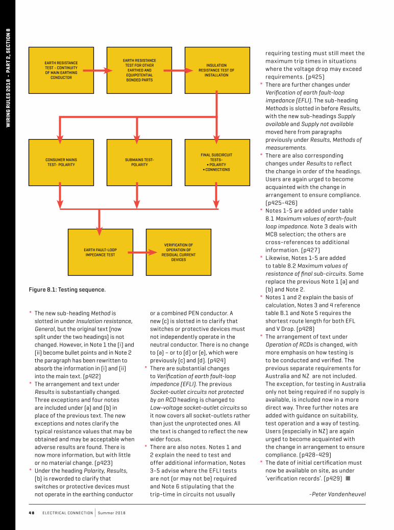
4 8 ELEC TRICAL CONNEC TION Summer 2018
* The new sub-heading Method is slotted in under Insulation resistance, General, but the original text (now split under the two headings) is not changed. However, in Note 1 the (i) and (ii) become bullet points and in Note 2 the paragraph has been rewritten to absorb the information in (i) and (ii) into the main text. (p422)
* The arrangement and text under Results is substantially changed. Three exceptions and four notes are included under (a) and (b) in place of the previous text. The new exceptions and notes clarify the typical resistance values that may be obtained and may be acceptable when adverse results are found. There is now more information, but with little or no material change. (p423)
* Under the heading Polarity, Results, (b) is reworded to clarify that switches or protective devices must not operate in the earthing conductor
or a combined PEN conductor. A new (c) is slotted in to clarify that switches or protective devices must not independently operate in the neutral conductor. There is no change to (a) – or to (d) or (e), which were previously (c) and (d). (p424)
* There are substantial changes to Verifi cation of earth fault-loop impedance (EFLI). The previous Socket-outlet circuits not protected by an RCD heading is changed to Low-voltage socket-outlet circuits so it now covers all socket-outlets rather than just the unprotected ones. All the text is changed to refl ect the new wider focus.
* There are also notes. Notes 1 and 2 explain the need to test and offer additional information, Notes 3-5 advise where the EFLI tests are not (or may not be) required and Note 6 stipulating that the trip-time in circuits not usually
requiring testing must still meet the maximum trip times in situations where the voltage drop may exceed requirements. (p425)
* There are further changes under Verifi cation of earth fault-loop impedance (EFLI). The sub-heading Methods is slotted in before Results, with the new sub-headings Supply available and Supply not available moved here from paragraphs previously under Results, Methods of measurements.
* There are also corresponding changes under Results to refl ect the change in order of the headings. Users are again urged to become acquainted with the change in arrangement to ensure compliance. (p425-426)
* Notes 1-5 are added under table 8.1 Maximum values of earth-fault loop impedance. Note 3 deals with MCB selection; the others are cross-references to additional information. (p427)
* Likewise, Notes 1-5 are added to table 8.2 Maximum values of resistance of fi nal sub-circuits. Some replace the previous Note 1 (a) and (b) and Note 2.
* Notes 1 and 2 explain the basis of calculation, Notes 3 and 4 reference table B.1 and Note 5 requires the shortest route length for both EFL and V Drop. (p428)
* The arrangement of text under Operation of RCDs is changed, with more emphasis on how testing is to be conducted and verifi ed. The previous separate requirements for Australia and NZ are not included. The exception, for testing in Australia only not being required if no supply is available, is included now in a more direct way. Three further notes are added with guidance on suitability, test operation and a way of testing. Users (especially in NZ) are again urged to become acquainted with the change in arrangement to ensure compliance. (p428-429)
* The date of initial certifi cation must now be available on site, as under ‘verifi cation records’. (p429) �
-Peter Vandenheuvel
WIR
ING
RU
LES
2018
- P
ART
2, S
ECTI
ON
8
Figure 8.1: Testing sequence.
S-CLICK TIME SWITCHES & PRESENCE DETECTORSIntroducing our new range of German manufactured Digital and Analogue Time Switches featuring large screw terminals, better suited for stranded conductors over DUO FIX spring terminals.
A complete range of Presence Detectors are also available. Choose from; Ceiling recessed flush mount PIR in either one or two channel variants, two channel surface mount PIR, high performance PIR with a 30 meter detection range, or a dual tech sensor featuring ultrasonic and PIR combination. They are also available in black.
www.sclick.com.au
In support of our policy of continuous product improvement we reserve the right to change materials and specifications without notice. Drawings, where shown, may not be to scale. Dimensions are metric and size maybe approximate. Where possible data sheets including MSDS are made available on our website and APPs. All products should be installed and used in accordance to manufacturer’s instruction provided. Warning: products may be subject of registered designs and patents. Refer to our website or APPs for terms and conditions on warranty. Every effort has been made to ensure accuracy of content. However no liability will be met by Legend Corporation or its suppliers for any errors or omissions. Product data and information is no binding. All brands and logos are registered trademarks and are subject to copyright laws. No part of this catalogue can be reproduced without the consent of Legend Corporation.
Smart Switch Technology. The Smartest Lighting Solution.
EARTH RESISTANCE TEST - CONTINUITY OF MAIN EARTHING
CONDUCTOR
CONSUMER MAINS TEST- POLARITY
EARTH FAULT-LOOP IMPEDANCE TEST
EARTH RESISTANCE TEST FOR OTHER
EARTHED AND EQUIPOTENTIAL BONDED PARTS
SUBMAINS TEST- POLARITY
VERIFICATION OF OPERATION OF
RESIDUAL CURRENT DEVICES
INSULATION RESISTANCE TEST OF
INSTALLATION
FINAL SUBCIRCUIT TESTS-
∫ POLARITY∫ CONNECTIONS

5 0 ELEC TRICAL CONNEC TION Summer 2018
TesTing Times
V erification is a term we know the meaning of but don’t do enough about.
We have grown accustomed to things changing rapidly and have developed a mindset of faster, stronger and better.
The key thing we look for is ‘better’. It leads us to believe that something is of higher quality or meets or exceeds our requirements and/or expectations.
This may be true on a product level but does it equate to the quality or correctness of your work?
In the world of Standards, verification is defined as: “confirmation, through the provision of objective evidence, that specified requirements have been fulfilled”; where objective evidence can be obtained by observation, measurement, test or other means.
With the recent publication of AS/NZS 3000:2018, it is a good time to remind ourselves about the objective evidence needed in relation to an electrical installation.
Clear requirements are set out in Section 8 of the Wiring Rules. In summary, the Standard provides
a checklist for observations and a mandatory series of tests. To assist with this process, the regulator for each state requires contractors to complete a legal document usually in the form of a certificate of compliance.
Referring to the definition above – other than ticking a box to say something was done, what objective evidence is there to show that it actually was done? Are your readings correct? What are the implications?
In the commercial world there is a common saying: “If it wasn’t written, it wasn’t done.” Government websites have clear guidelines and recommendations for business-related documents. Legally, records are to be kept for seven years.
Although inspectors check an installation before authorising the supply of power, is the responsibility of verification and liability on their shoulders? The answer is no.
Records in all states have shown that people have died due to installation errors – where power has been supplied – and it is always the electrician who must answer the questions.
If the relevant evidence of installation records can be provided on request, this mitigates many of the installation issues in the industry today. Section 8.4 of the Standard calls for the necessity of proper record keeping: “In order to enable re-verification of an installation, it is necessary to know the details of the original verification.”
Using an exaggerated example, when you go to the doctor for a test, you trust the results and hope they give you good news. How would you feel if the doctor told you the results were good but you later found out that the readings were wrong?
In the field of measurement, your results are only as good as the accuracy of your tools and methods. Which brings a question to light: when were your tools of trade last calibrated? Although it is not stated in AS/NZS 3000, it is stipulated in AS/NZS 3017 Electrical installations - Verification guidelines, which the wiring rules references in the event of verification.
The unfortunate attitude of ‘she’ll be right’ is often the main reason for neglect in this area. Contractors are generally unaware of the possible legal repercussions when something goes wrong because of an incorrect reading.
Calibration is an adjustment of a meter/device to a known reference. Checking against another meter is a good start, but how do you know which reading is correct? And both devices might have been inaccurate to start with.
Due to the environment in which electrical contractors work, the equipment is subjected to harsher treatment than it would in a test lab.
Modern instruments are more robust, and are much more advanced and accurate than ever before, yet many things may affect measurement quality. These include exposure to magnetic fields, temperature, humidity, shock and vibration, frequency of use, etc.
According to the Wiring Rules, verification is a legal requirement and should be integral to a contractor’s work. Vincent Law from Hager Electro explains.
WiR
ing
RU
Les
2018
- p
aRT
2, s
ecTi
on
8

w w w.electr icalconnection.com.au 5 1
If unchecked, an instrument may be ‘off’ without the user realising until something goes wrong.
In many fields of work, commissioning and installation verification is unfortunately often viewed and treated as a tick of the box. With the effort taken to design and install the equipment, why is installation testing seen as an inconvenience?
One of the biggest changes in the latest revision of AS/NZS 3000 is the requirement for a residual current device (RCD) on every sub-circuit.
With the extra equipment required for an installation, it is crucial to ensure that each aspect has been tested and verified. The Standard mandates that checks on RCDs be performed as part of the verification process.
Reputable product manufacturers jump through hoops and walk through fire to ensure their products are safe, and compliant to national and international Standards as well as local rules and regulations.
Quite often, the design and testing process begins years in advance so that a product is available as soon as rule changes are implemented. It is a rigorous and robust process, but at times manufacturers are let down by customers. There are contractors who fail to check their own work and misuse a product, which may lead to the unnecessary banning of perfectly functional products.
The role of the regulator in the electrical installation environment is to enforce the rules and issue penalties for non-compliances. Examples are seen in regular bulletins where offences are published with the corresponding penalty. Some lists clearly show the lack of regard for testing on the contractor side.
On a wider note, this is not just a matter of monetary penalties, it is a blatant lack of duty of care for co-workers and end users. It harms the people involved – and gives the industry a bad name.
From the issues highlighted in this article, the key point is that verification should not be treated as an afterthought. Verification is a legal requirement and it should be integral to the work you do.
Your actions (or lack of) have a greater effect than you may think. ■
WIRIN
G RU
LES 2018 - paRt 2, SEctIo
N 8
Vincent Law is quality and compliance manager at Hager Electro. Previously, he was the verification and validation manager for a supplier in the HVAC industry. He has a Masters is Engineering Science.
Lindsay Lucas is engineering manager for Eaton’s ANZ Power Distribution business and has a long tenure with Eaton, Cutler-Hammer and Email-Westinghouse. He is a member of Standards Australia committees EL-001 Wiring Rules, EL-004 Electrical Accessories, and EL-006 Industrial Switchgear and Controlgear.
Legrand technical director Dennis Galvin is an Australian Industries Group representative of the EL-001 committee responsible for changes to the Standards covering installation requirements.
Since 1997, Gary Busbridge has been involved with the development of various Australian Standards in the electrical sector. He is standardisation manager at Clipsal and is the chairman of EL-001.
Principal of Vandenheuvel Consulting, Peter Vandenheuvel is the past managing director of Nilsen and former president of NECA. He is a member of EL-001.
ElEctrical connEction WoULd LIkE to makE SpEcIaL mENtIoN of thE foLLoWING INdUStRy LEadERS foR thEIR
coNtRIbUtIoN to thIS WIRING RULES SUppLEmENt. WIthoUt thEm, It WoULdN’t ExISt.
Being a member of the EL-001 Committee, which is responsible for producing the Wiring Rules, is a largely-thankless task. For the 35 members of the committee,
it involves painstakingly combing through associated reference standards, public comments and hours of debate and discussion (which at times, presumably,
becomes quite heated). The process is lengthy, spanning many years from inception to publication, and the members of the Committee aren’t often compensated
for their time (in addition to their usual employment, that is). Well, at Electrical Connection, we would like to thank the members of
EL-001 for all of the hard work they have done to ensure the creation of a document that embraces modern technologies and best practices.
It’s not an easy feat, so congratulatIons on a job well done!