aspect-oriented evolution of legacy information … · alap has been implemented in the aspectual...
TRANSCRIPT

ASPECT-ORIENTED EVOLUTION OFLEGACY INFORMATION SYSTEMS
a thesis
submitted to the department of computer engineering
and the institute of engineering and science
of bilkent university
in partial fulfillment of the requirements
for the degree of
master of science
By
Yasemin Satıroglu
August, 2004

I certify that I have read this thesis and that in my opinion it is fully adequate,
in scope and in quality, as a thesis for the degree of Master of Science.
Prof. Dr. H. Altay Guvenir (Advisor)
I certify that I have read this thesis and that in my opinion it is fully adequate,
in scope and in quality, as a thesis for the degree of Master of Science.
Asst. Prof. Dr. Bedir Tekinerdogan
I certify that I have read this thesis and that in my opinion it is fully adequate,
in scope and in quality, as a thesis for the degree of Master of Science.
Asst. Prof. Dr. Ali Aydın Selcuk
Approved for the Institute of Engineering and Science:
Prof. Dr. Mehmet B. BarayDirector of the Institute
ii

ABSTRACT
ASPECT-ORIENTED EVOLUTION OF LEGACYINFORMATION SYSTEMS
Yasemin Satıroglu
M.S. in Computer Engineering
Supervisor: Prof. Dr. H. Altay Guvenir
August, 2004
A legacy information system is an old system that typically has been developed
several years ago, and remains in operation within an organization. Since the soft-
ware requirements change, legacy systems must be evolved accordingly. Various
approaches such as wrapping, migration and redevelopment have been proposed
to maintain legacy information systems. Unfortunately, these approaches have
not explicitly considered the concerns that are difficult to capture in single com-
ponents, and tend to crosscut many components. Examples of such crosscutting
concerns include distribution, synchronization, persistence, security, logging and
real-time behavior. The crosscutting property of concerns seriously complicates
the maintenance of legacy systems because the code of the system needs to be
changed at multiple places, and conventional maintenance techniques fall short
to do this effectively.
Aspect-Oriented Software Development (AOSD) provides explicit mechanisms
for coping with these crosscutting concerns. However, current AOSD approaches
have primarily focused on coping with crosscutting concerns in software systems
that are developed from scratch. Hereby, the crosscutting concerns are imple-
mented as aspects at the beginning, hence localized in single modules. In this
way the implementation and maintenance of crosscutting concerns can be pre-
pared to a large extent so that the maintenance of these systems will be easier
later on. Unfortunately, legacy systems impose harsher requirements, because
crosscutting concerns in legacy systems are neither explicitly identified nor have
been prepared before.
We provide a systematic process for analyzing the impact of crosscutting con-
cerns on legacy systems. The process, which is called Aspectual Legacy Analysis
Process (ALAP), consists of three sub-processes, Feasibility Analysis, Aspectual
iii
iv
Analysis and Maintenance Analysis. All the three sub-processes consist of a set of
heuristic rules and the corresponding control. Feasibility Analysis, which consists
of two phases, describes rules for categorizing legacy systems, in the first phase;
and describes the rules for evaluating legacy systems with respect to the ability
to implement static crosscutting and ability to implement dynamic crosscutting,
in the second phase. The rules of the first phase are based on the categories of
legacy systems that we have defined after a thorough study to legacy information
systems, and the rules of the second phase are based on our discussion of these
categories with respect to crosscutting implementation. Once the legacy system
has been categorized and evaluated with respect to crosscutting implementation,
the Aspectual Analysis sub-process describes rules for identifying and specifying
aspects in legacy systems. Based on the results of the Feasibility Analysis and
Aspectual Analysis sub-processes, the Maintenance Analysis describes the rules
for the selection of the appropriate legacy maintenance approach.
ALAP has been implemented in the Aspectual Legacy Analysis Tool (ALAT),
which implements the rules of the three sub-processes and as such helps to sup-
port the legacy maintainer in analyzing the legacy system and identifying the
appropriate maintenance approach.
Keywords: Legacy Information Systems, Aspect-Oriented Software Development,
Heuristic Rule Modelling.

OZET
MIRAS BILGI SISTEMLERININ ILGIYE-YONELIKGELISTIRIMI
Yasemin Satıroglu
Bilgisayar Muhendisligi, Yuksek Lisans
Tez Yoneticisi: Prof. Dr. H.Altay Guvenir
Agustos, 2004
Miras sistem, bircok yıl once gelistirilen ve bir kurulusta kullanılmaya de-
vam edilen sistemdir. Yazılım gereksinimleri degistikce miras sistemler de uy-
gun olarak gelistirilmelidir. Miras sistemlerin bakımı icin sarma, tasıma ve
yeniden gelistirme gibi bircok yontem onerilmistir. Maalesef, bu yontemler tek
bir bilesende yakalanması guc, ve bircok bileseni enine kesme egiliminde olan
ozellikleri acıkca goz onunde bulundurmamıslardır. Dagıtım, es zamanlama, de-
vamlılık, guvenlik, kayıt tutma ve gercek zaman davranısı, enine kesen ozellik
ornekleri arasındadır. Bu ozelliklerin enine kesme niteligi miras sistemlerin
bakımını ciddi anlamda karmasıklastırır, cunku, sistemin kodunun birden fazla
yerde degistirilmesini gerektirir ve geleneksel bakım teknikleri bu islemi etkili
olarak gerceklestirmede yetersiz kalmaktadır.
Ilgiye-Yonelik Yazılım Gelistirme enine kesen ozellikler ile basa cıkmak icin
kesin mekanizmalar saglar. Fakat gecerli Ilgiye-Yonelik Yazılım Gelistirme
teknikleri, esas olarak, sıfırdan gelistirilen yazılım sistemleri icerisindeki enine
kesen ozellikler ile bas etmek uzerine odaklanmıs durumdadır. Bu sistemlerde
enine kesen ozellikler baslangıcta birer ilgi olarak gerceklestirilerek tek bir bilesen
icerisine yerlestirilebilir. Bu sekilde, enine kesen ozelliklerin gerceklestirim ve
bakımı buyuk capta duzenlenebilir, ki bu da sistemin ilerideki bakımını ko-
laylastıracaktır. Ne yazık ki, miras sistemler daha sert gereksinimler yuklerler,
cunku miras sistemlerde enine kesen ozellikler onceden acık olarak tanımlanamaz
ve duzenlenemez. Bununla beraber, enine kesen ozellikler ile bas etmek icin uygun
tekniklerin eksikligi miras sistemlerin bakımını carpıcı bir bicimde engeller.
Bu tezde, miras sistemlerin analizi icin sistematik bir surec tanımlanmaktadır.
Ilgiye-Yonelik Miras Analiz Sureci isimli bu surec, Olurluk Analizi, Ilgiye-Yonelik
Analiz ve Bakım Analizi olmak uzere uc alt surecten olusur. Herbir alt surec, bir
v

vi
bulussal kurallar kumesi ve bunlara iliskin kontrol mekanizmasından olusur. Iki
asamadan olusan Olurluk Analizi, birinci asamada miras sistemlerin kategoriza-
syonu ile ilgili kuralları, ikinci asamada da miras sistemlerin, statik ve dinamik
enine kesme gerceklestirim yetenegine gore degerlendirilmesi ile ilgili kuralları
tanımlar. Ilk asamada tanımlanan kurallar, miras sistemler hakkında derinleme-
sine bir calısma sonrasında tanımladıgımız miras sistem kategorilerine dayan-
maktadır. Ikinci asamada tanımlanan kurallar da bu kategorilerin enine kesme
gerceklestirimi uzerine yaptıgımız tartısmaya dayanmaktadır. Miras sistem kate-
gorize edilip enine kesme gerceklestirimine gore degerlendirildikten sonra, Ilgiye-
Yonelik Analiz, miras sistemdeki ilgilerin teshis edilmesi ve belirtilmesi ile ilgili
kuralları tanımlar. Bakım Analizi, Olurluk Analizi ve Ilgiye-Yonelik Analiz alt
sureclerinin sonuclarına dayanarak miras sistem icin uygun bakım yaklasımının
secimi ile ilgili kuralları tanımlar.
Bu alt surecler, herbir alt surecle ilgili kuralları gerceklestiren, ve bu
sekilde, miras sistemin bakımını yapan kisiye, miras sistemin analizi ve uygun
bakım yaklasımının belirlenmesinde yardım saglayan Ilgiye-Yonelik Miras Anal-
izi Aracı’nda gerceklestirilmistir.
Anahtar sozcukler : Miras Bilgi Sistemleri, Ilgiye-Yonelik Yazılım Gelistirme,
Bulussal Kural Modellemesi.

Acknowledgement
I am deeply grateful to my de facto supervisor Asst. Prof. Dr. Bedir Tekin-
erdogan, who has guided me with his invaluable suggestions and criticisms, and
provided me a great support. He encouraged and helped me a lot, in all the time
of research for and writing of this thesis. It was a great pleasure for me to have
a chance of working with such a valuable and kind person.
I would also like to express my special thanks to Prof. Dr. H. Altay Guvenir
and Asst. Prof. Dr. Ali Aydın Selcuk, for their valuable comments.
Above all, I would like to express my deep sense of gratitude to my precious
family; my mother Emine, my father Adnan, and my elder sister Esra; for their
endless love. Without their great support and encouragement, I could never
complete this thesis. I love them and I thank God every day for being a member
of such a lovely family.
vii

Contents
1 Introduction 1
1.1 Problem Statement . . . . . . . . . . . . . . . . . . . . . . . . . . 1
1.2 Contribution . . . . . . . . . . . . . . . . . . . . . . . . . . . . . . 3
1.3 Outline of Thesis . . . . . . . . . . . . . . . . . . . . . . . . . . . 5
2 Categorization of Legacy Systems 6
2.1 Background . . . . . . . . . . . . . . . . . . . . . . . . . . . . . . 6
2.2 Legacy System Categories . . . . . . . . . . . . . . . . . . . . . . 9
2.2.1 Categorization Based on Criticality . . . . . . . . . . . . . 10
2.2.2 Categorization Based on Health State . . . . . . . . . . . . 10
2.2.3 Categorization Based on Accessibility . . . . . . . . . . . . 11
2.3 Legacy System Maintenance Approaches . . . . . . . . . . . . . . 12
2.3.1 Wrapping . . . . . . . . . . . . . . . . . . . . . . . . . . . 12
2.3.2 Migration . . . . . . . . . . . . . . . . . . . . . . . . . . . 14
2.3.3 Redevelopment . . . . . . . . . . . . . . . . . . . . . . . . 14
viii

CONTENTS ix
2.4 Analysis of Legacy System Maintenance Approaches . . . . . . . . 15
2.4.1 Wrapping . . . . . . . . . . . . . . . . . . . . . . . . . . . 15
2.4.2 Migration . . . . . . . . . . . . . . . . . . . . . . . . . . . 16
2.4.3 Redevelopment . . . . . . . . . . . . . . . . . . . . . . . . 21
2.5 Legacy System Design Space . . . . . . . . . . . . . . . . . . . . . 22
2.6 Summary . . . . . . . . . . . . . . . . . . . . . . . . . . . . . . . 23
3 Crosscutting Concerns in Legacy Systems 24
3.1 Case Study: Drugstore Information System . . . . . . . . . . . . . 24
3.2 Enhancing the Legacy System . . . . . . . . . . . . . . . . . . . . 26
3.3 Problem Statement . . . . . . . . . . . . . . . . . . . . . . . . . . 28
4 Aspect-Oriented Software Development 30
4.1 Introduction . . . . . . . . . . . . . . . . . . . . . . . . . . . . . . 30
4.2 Basics of AOP . . . . . . . . . . . . . . . . . . . . . . . . . . . . . 32
4.3 AOSD Approaches . . . . . . . . . . . . . . . . . . . . . . . . . . 33
4.3.1 AspectJ . . . . . . . . . . . . . . . . . . . . . . . . . . . . 34
4.3.2 Composition Filters . . . . . . . . . . . . . . . . . . . . . . 39
4.3.3 Hyper/J . . . . . . . . . . . . . . . . . . . . . . . . . . . . 49
4.3.4 DJ . . . . . . . . . . . . . . . . . . . . . . . . . . . . . . . 59
5 ALAP: Aspectual Legacy Analysis Process 64

CONTENTS x
5.1 Top-Level Process . . . . . . . . . . . . . . . . . . . . . . . . . . . 64
5.2 Feasibility Analysis . . . . . . . . . . . . . . . . . . . . . . . . . . 65
5.2.1 Categorization phase . . . . . . . . . . . . . . . . . . . . . 67
5.2.2 Crosscutting evaluation phase . . . . . . . . . . . . . . . . 70
5.3 Aspectual Analysis . . . . . . . . . . . . . . . . . . . . . . . . . . 73
5.3.1 Rules . . . . . . . . . . . . . . . . . . . . . . . . . . . . . . 74
5.3.2 Evaluation . . . . . . . . . . . . . . . . . . . . . . . . . . . 75
5.3.3 Control of the Rules . . . . . . . . . . . . . . . . . . . . . 75
5.4 Maintenance Analysis . . . . . . . . . . . . . . . . . . . . . . . . . 76
5.4.1 Rules . . . . . . . . . . . . . . . . . . . . . . . . . . . . . . 76
5.5 Summary . . . . . . . . . . . . . . . . . . . . . . . . . . . . . . . 78
6 ALAT: Aspectual Legacy Analysis Tool 79
6.1 General Structure . . . . . . . . . . . . . . . . . . . . . . . . . . . 79
6.2 Interface Part . . . . . . . . . . . . . . . . . . . . . . . . . . . . . 80
6.2.1 Analysis Data Tool . . . . . . . . . . . . . . . . . . . . . . 80
6.2.2 Add/Update/Remove Rule Tool . . . . . . . . . . . . . . . 85
6.2.3 Analysis Processes Tool . . . . . . . . . . . . . . . . . . . 87
6.2.4 Reports Tool . . . . . . . . . . . . . . . . . . . . . . . . . 90
6.3 Application Logic Part . . . . . . . . . . . . . . . . . . . . . . . . 93
6.4 Database Part . . . . . . . . . . . . . . . . . . . . . . . . . . . . . 94

CONTENTS xi
6.5 Summary . . . . . . . . . . . . . . . . . . . . . . . . . . . . . . . 96
7 Aspectual Refactoring 97
7.1 Definition . . . . . . . . . . . . . . . . . . . . . . . . . . . . . . . 97
7.2 Aspectual Refactoring Techniques . . . . . . . . . . . . . . . . . . 99
7.2.1 Extract method calls . . . . . . . . . . . . . . . . . . . . . 100
7.2.2 Extract introduction . . . . . . . . . . . . . . . . . . . . . 101
7.2.3 Extract interface implementation . . . . . . . . . . . . . . 102
7.2.4 Extract exception handling . . . . . . . . . . . . . . . . . . 103
7.2.5 Replace override with advice . . . . . . . . . . . . . . . . . 103
8 Conclusions 108

List of Figures
2.1 Classic decision matrix . . . . . . . . . . . . . . . . . . . . . . . . 9
2.2 Wrapping technique . . . . . . . . . . . . . . . . . . . . . . . . . . 13
2.3 Chicken Little strategy . . . . . . . . . . . . . . . . . . . . . . . . 20
3.1 Class diagram of Drugstore Information System . . . . . . . . . . 26
4.1 Components of the CF model [7] . . . . . . . . . . . . . . . . . . 39
4.2 Structure of a filter specification . . . . . . . . . . . . . . . . . . . 40
4.3 Message evaluation by filters . . . . . . . . . . . . . . . . . . . . . 43
4.4 Class diagram of the Mail System . . . . . . . . . . . . . . . . . . 45
4.5 Aggregation-based composition of multiple views . . . . . . . . . 46
4.6 Inheritance-based composition of multiple views . . . . . . . . . . 47
4.7 Filter definition for class USViewMail . . . . . . . . . . . . . . . . 48
4.8 Personnel Software class diagram . . . . . . . . . . . . . . . . . . 54
4.9 Addition of export functionality . . . . . . . . . . . . . . . . . . . 56
4.10 Hyperspace solution - Step 1 . . . . . . . . . . . . . . . . . . . . . 56
xii

LIST OF FIGURES xiii
4.11 Hyperspace solution - Step 2 . . . . . . . . . . . . . . . . . . . . . 57
4.12 Hyperspace solution - Step 3 . . . . . . . . . . . . . . . . . . . . . 57
4.13 Hyperspace solution - Step 4 and Step 5 . . . . . . . . . . . . . . 58
4.14 Hyperspace solution - Step 6 . . . . . . . . . . . . . . . . . . . . . 58
4.15 An example traversal strategy . . . . . . . . . . . . . . . . . . . . 61
4.16 An example adaptive method . . . . . . . . . . . . . . . . . . . . 63
5.1 Aspectual Legacy Analysis Process (ALAP) . . . . . . . . . . . . 66
5.2 Feasibility Analysis rules (Categorization phase) . . . . . . . . . . 68
5.3 Evaluation approach for the Categorization phase of Feasibility
Analysis . . . . . . . . . . . . . . . . . . . . . . . . . . . . . . . . 69
5.4 Feasibility Analysis rules (Crosscutting evaluation phase) . . . . . 73
5.5 Aspectual Analysis rules . . . . . . . . . . . . . . . . . . . . . . . 74
5.6 Evaluation approach for the rules of Aspectual Analysis . . . . . . 75
5.7 Maintenance Analysis rules . . . . . . . . . . . . . . . . . . . . . . 78
6.1 Structure of the Interface part of the ALAT . . . . . . . . . . . . 80
6.2 Launcher of ALAT . . . . . . . . . . . . . . . . . . . . . . . . . . 81
6.3 Analysis Data Tool . . . . . . . . . . . . . . . . . . . . . . . . . . 81
6.4 Criteria Definition Tool . . . . . . . . . . . . . . . . . . . . . . . . 82
6.5 Criteria Evaluation Tool . . . . . . . . . . . . . . . . . . . . . . . 83
6.6 Rule Order Tool . . . . . . . . . . . . . . . . . . . . . . . . . . . . 84

LIST OF FIGURES xiv
6.7 Maintenance Activity Tool . . . . . . . . . . . . . . . . . . . . . . 85
6.8 Add/Update/Remove Rule Tool . . . . . . . . . . . . . . . . . . . 86
6.9 Add Rule Tool . . . . . . . . . . . . . . . . . . . . . . . . . . . . 86
6.10 Update Rule Tool . . . . . . . . . . . . . . . . . . . . . . . . . . . 87
6.11 Remove Rule Tool . . . . . . . . . . . . . . . . . . . . . . . . . . 88
6.12 Analysis Processes Tool . . . . . . . . . . . . . . . . . . . . . . . 88
6.13 Analysis Tool (Feasibility Analysis performed) . . . . . . . . . . . 89
6.14 Analysis Tool (Aspectual Analysis performed) . . . . . . . . . . . 90
6.15 Reports Tool . . . . . . . . . . . . . . . . . . . . . . . . . . . . . 90
6.16 View Report Tool (Feasibility Report) . . . . . . . . . . . . . . . 91
6.17 View Report Tool (Concern Report) . . . . . . . . . . . . . . . . 91
6.18 View Report Tool (Maintenance Report) . . . . . . . . . . . . . . 92
6.19 Class diagram of the ALAT . . . . . . . . . . . . . . . . . . . . . 93
7.1 Doctor, Drugstore and Patient classes before any refactoring . . . 98
7.2 Doctor, Drugstore and Patient classes after conventional refactoring 99
7.3 Extract method calls refactoring [23] . . . . . . . . . . . . . . . . 100
7.4 Doctor, Drugstore and Patient classes after aspectual refactoring . 101
7.5 LoggerAspect.java . . . . . . . . . . . . . . . . . . . . . . . . . . . 102
7.6 Class MainSystem before applying any aspectual refactoring . . . 104

LIST OF FIGURES xv
7.7 FrmDoc, FrmDS and FrmPres classes before applying any aspec-
tual refactoring . . . . . . . . . . . . . . . . . . . . . . . . . . . . 105
7.8 FrmDoc, FrmDS and FrmPres classes after applying extract ex-
ception handling aspectual refactoring . . . . . . . . . . . . . . . 106
7.9 Class MainSystem after applying extract exception handling as-
pectual refactoring . . . . . . . . . . . . . . . . . . . . . . . . . . 107
7.10 ExceptionHandlerAspect.java . . . . . . . . . . . . . . . . . . . . 107
List of Tables
2.1 Legacy system categories vs. evolution approaches . . . . . . . . . 23
5.1 Evaluation of legacy system categories with respect to static and
dynamic crosscutting . . . . . . . . . . . . . . . . . . . . . . . . . 72
6.1 Rules table . . . . . . . . . . . . . . . . . . . . . . . . . . . . . . 94
6.2 Criteria table . . . . . . . . . . . . . . . . . . . . . . . . . . . . . 95
6.3 Approach table . . . . . . . . . . . . . . . . . . . . . . . . . . . . 95
xvi
Chapter 1
Introduction
A legacy software system may be defined informally as an old system that re-
mains in operation within an organization [41]. Legacy systems typically have
been developed several years ago, sometimes without anticipating that they would
be still running much later. Inevitably the software requirements for legacy sys-
tems might change and legacy systems must be evolved accordingly. Maintaining
legacy systems, however, is, in general, difficult because legacy systems very often
run on obsolete, slow hardware that is hard to maintain, the documentation of
the legacy system is lacking or incomplete, the interfaces of the legacy system
components are limited for integration and/or adaptation, etc. Organizations
dealing with legacy systems can either decide to replace the system or maintain
the system. A simple replacement, if possible at all, might be desirable but too
expensive to consider because of the huge volumes of necessary changes, or too
risky because of the continuous demand for on-line operation.
1.1 Problem Statement
Several viable solutions such as reengineering [39] and system reengineering pat-
terns [34] have been proposed for maintaining legacy systems. In principle, legacy
systems are enhanced using one of the three techniques: wrapping, migration, and
1

CHAPTER 1. INTRODUCTION 2
redevelopment [9]. The possible maintenance approaches differ according to the
type of the legacy system. Given a concrete legacy system problem, it is not,
however, always possible to categorize the solution according to one problem [9]
and often combinations of these techniques are used.
Conventional maintenance approaches have generally focused on, or are basi-
cally good at, coping with non-crosscutting concerns. Hereby, the maintenance
and evolution requirements impact single components and can be more easily
localized. However, it appears that several concerns cannot be easily localized in
single components and tend to be scattered over multiple components. These so-
called crosscutting concerns severely hinder the maintenance and the adaptability
of software systems.
In contrast, crosscutting evolution requirements have to deal with evolution
of concerns that tend to crosscut several components. Required changes to these
concerns are difficult because these changes need to be performed at multiple
places impeding even further the maintainability. One basic reason why legacy
systems are usually associated with high maintenance costs is because of the
inflexibility of the adopted techniques [6]. In case crosscutting concerns are not
appropriately addressed, the continuous maintenance of legacy systems might
thus easily lead to a degradation of its structure and as such its maintainability.
This might manifest itself in the following ways:
• Updating existing concerns
If existing concerns such as for example, synchronization, recovery, logging,
are not modularized in the legacy system, then they will be scattered over
different components. The maintenance of these concerns will therefore
need to take place at several places. For this all the affected components in
the legacy system must be identified first, which is definitely not a trivial
task. Furthermore, the affected components need to be changed appropri-
ately. This whole process does not only seriously impede updating these
concerns, but also is a tedious and error-prone activity.
CHAPTER 1. INTRODUCTION 3
• Inserting new crosscutting concerns
Inserting concerns that crosscut over multiple components results in a sim-
ilar effect as updating existing concerns. In this case, inserting crosscutting
concerns requires finding the components in the legacy system which are
affected, but do not include the concern yet. This lack of additional in-
formation might even further complicate the identification of the affected
components. Once the components have been identified, similar to updating
concerns the legacy code must be enhanced.
The Aspect-Oriented Software Development (AOSD) community has provided
several general purpose solutions for coping with aspects in software systems.
Unfortunately, existing AOSD approaches seem to have primarily focused on
identifying, specifying and implementing aspects for systems that are developed
from scratch. Identifying, updating and specifying aspects in legacy information
systems impose common but also different requirements and constraints on the
maintenance. As such, the application of aspect-oriented techniques to maintain-
ing legacy systems seems to be a worthwhile attempt.
1.2 Contribution
The contribution of this thesis is as follows:
• Categorization of legacy systems
To reason about legacy systems we provide a categorization on the various
legacy systems as described in the literature. Based on our literature survey
and the existing categorizations, we categorize legacy systems according to
the criteria of criticality to business needs, health state and accessibility.
• Selecting the maintenance approaches for legacy system categories
In parallel with the categorization of legacy systems, we provide an analysis
of existing legacy maintenance approaches. For each legacy system category,
the required (conventional) legacy maintenance techniques are described.
CHAPTER 1. INTRODUCTION 4
• Identification of crosscutting concerns problem in legacy systems
We identify the crosscutting concerns problem in legacy information sys-
tems, utilizing a general case study, Drugstore Information System. Since
existing maintenance approaches do not explicitly consider crosscutting con-
cerns they fall short to maintain the legacy system appropriately.
• Defining a process for analyzing legacy systems in case of crosscutting con-
cerns
Existing legacy maintenance approaches do not explicitly consider the pro-
cess for maintaining the legacy system (also) based on crosscutting con-
cerns. We provide a process called ALAP, for analyzing legacy systems
both for crosscutting concerns and non-crosscutting concerns. ALAP con-
sists of Feasibility Analysis, Aspectual Analysis and Maintenance Analysis
sub-processes. Feasibility Analysis, which consists of two phases, defines
a categorization of the legacy system in the first phase, and evaluates the
legacy system with respect to the ability to implement static and dynamic
crosscutting in the second phase. Aspectual Analysis provides a systematic
analysis on the impact of the concern on the corresponding legacy system,
and determines whether the concern is crosscutting or not. Finally, Mainte-
nance Analysis provides the required maintenance techniques which might
include conventional techniques or aspectual techniques, according to the
results of the first two sub-processes.
• Explicit reasoning on modularizing aspects of legacy systems
In the second phase of Feasibility Analysis sub-process of ALAP, we explain
how different legacy systems behave differently with respect to crosscutting
implementation. For each category of the legacy system we provide an anal-
ysis of the implementation of crosscutting concerns. We describe explicit
rules for identifying and specifying aspects in legacy systems, in the Aspec-
tual Analysis sub-process of ALAP. Also, aspectual refactoring of legacy
systems, which apply aspectual techniques to integrate or update new con-
cerns is explained by some examples.

CHAPTER 1. INTRODUCTION 5
1.3 Outline of Thesis
The thesis is organized as follows: Chapter 2 provides an overview and the catego-
rization of legacy systems, and the conventional legacy maintenance approaches.
Chapter 3 explains the crosscutting concern problem, and introduces an example
case, Drugstore Information System. Chapter 4 provides an overview of AOSD,
and explains how AOSD deals with crosscutting concerns. Chapter 5 explains
the ALAP, the systematic process we have defined. Chapter 6 presents ALAT,
the tool we have developed in order to automate the ALAP. Chapter 7 explains
several aspectual refactoring techniques. Finally, Chapter 8 presents the conclu-
sions.
Chapter 2
Categorization of Legacy Systems
In this chapter we provide the background on legacy systems and analyze the
various legacy maintenance approaches. Section 2.1 provides a general overview
of legacy systems. Section 2.2 describes the criteria for categorization that we
apply. Section 2.3 presents the conventional maintenance approaches. Section
2.4 provides the analysis of conventional legacy maintenance approaches. Finally,
Section 2.5 explains the design space of legacy systems.
2.1 Background
Legacy systems are the software systems that typically have been developed sev-
eral years ago (sometimes 20-30 years ago), sometimes without anticipating that
they would be still running decades later. They have been constructed without
having the ability to change as a first-class design goal. Many of these systems
were developed using technologies that are now obsolete. These systems are still
business critical, that is, they are essential for the normal functioning of the busi-
ness. They are typically the backbone of an organization’s information flow and
their failure can have serious impact on business [9].
It is possible to collect a large number of definitions of legacy systems:
6
CHAPTER 2. CATEGORIZATION OF LEGACY SYSTEMS 7
• A legacy software system may be defined informally as an old system that
remains in operation within an organization [41].
• Legacy systems are large software systems that we do not know how to cope
with but that are vital to our organization [6].
• A legacy software system is a computer system or an application program,
which continues to be used because of the prohibitive cost of replacing or
redesigning it and despite its poor competitiveness and compatibility with
modern equivalents. The implication is that the system is large, monolithic,
and difficult to modify [2].
• A legacy system is any information system that significantly resists mod-
ification and evolution to meet new and constantly changing business re-
quirements [12].
Inevitably the software requirements for legacy systems might change and
legacy systems must be evolved accordingly. This is however easier said than
done because legacy systems significantly resist change, in general. The reasons
for this might be because legacy systems run on obsolete, slow hardware that
is hard to maintain; the documentation of the legacy system is lacking, incom-
plete or out of date; the interfaces of the legacy system components are limited
for integration and/or adaptation; different parts are implemented by different
teams without any consistent programming style; the system structure may be
corrupted by many years of maintenance; techniques to save space or increase
speed at the expense of understandability may have been used, etc. Maintenance
and understanding of legacy software can pose problems, particularly when the
original programmers have left, and replacement staff do the modifications. Due
to individual programming styles, developed programs could be difficult to under-
stand and maintain. Over time, source code maintenance has changed the original
software specification and design. However, as is often the case, the specifications
and design have not been updated. Thus, program design and understanding is
lost, and the only documentation of the system is the source code itself.
It is inappropriate to always assume that legacy systems are bad. In many

CHAPTER 2. CATEGORIZATION OF LEGACY SYSTEMS 8
situations, the legacy leftover can be very important and valuable. In particular,
legacy systems have typically evolved over many years to reflect subtle and tacit
business process knowledge, unlikely to be recaptured in a replacement system
without years of debugging effort. This hard-won robustness makes a legacy
system a troublesome burden. Here lies the legacy system dilemma: a legacy
system is both a business asset and a business liability; businesses cannot afford
to keep them, and cannot afford to do without them.
The overriding problem for the industry is deciding what to do with its legacy
software. Organizations dealing with legacy systems can either decide to replace
the system or maintain the system. A simple replacement, if possible at all,
might be desirable but too expensive to consider because of the huge volumes
of necessary changes, or too risky because of the continuous demand for on-line
operation. There is a significant business risk in simply scrapping a legacy system
and replacing it with a system that has been developed using modern technology
since business processes are reliant on the legacy system. Also, the processes
involved in a legacy system have generally been there for some time and have
widespread usage and acceptance within the organization. It is very unlikely
that the benefits of legacy systems, like widespread usage and acceptance can
be transferred instantly. Because of these reasons, legacy systems are continu-
ously adapted to cope with the evolution requirements. A successful sustainment
and modernization program can keep systems current with changing business
and technology requirements while saving time, money, and IT staff resources.
Preventing systems from slowly becoming legacy systems requires active sustain-
ment. Sustainment means taking time to repair defects correctly and not simply
patching the code. By this way, maintainability and evolvability of the code may
be retained even as modification requests are satisfied. Sustainment may require
technology refresh and architectural evolution. To avoid obsolescence, the sus-
tainment budget must exceed that used for simple maintenance and let the IT
team keep pace with changing technology and evolving business needs.
The classic decision matrix, which is shown in Figure 2.1, shows the options
that can be considered when deciding what to do with a legacy system [34]:

CHAPTER 2. CATEGORIZATION OF LEGACY SYSTEMS 9
System quality
Maintain Enhance
Discard Reengineer
Business value
Figure 2.1: Classic decision matrix
• Systems that are very valuable for the business but are too hard to change
to be enhanced without restructuring are good candidates for reengineer-
ing. These make an important business contribution but are expensive to
maintain. They should be reengineered.
• Systems with low business value and low quality are candidates for replace-
ment with commercial packages. They can be discarded.
• Systems with high quality and low business value can be maintained with
continued low level maintenance activities.
• Systems with high quality and high business value should be actively sus-
tained to avoid degradation. They should be enhanced.
2.2 Legacy System Categories
Legacy Systems can be categorized in different ways based on various adapted
criteria. In the following, we will categorize legacy systems based on the criteria
of criticality, health state and accessibility. These criteria have been derived from
the literature on legacy systems.

CHAPTER 2. CATEGORIZATION OF LEGACY SYSTEMS 10
2.2.1 Categorization Based on Criticality
This categorization is done according to the business criticality criterion. The
legacy system types in this categorization are mission critical and replaceable
legacy system types.
Mission critical systems are the systems that are essential to the continued
operation of the business, and, that provide service on which the organization is
highly dependent. A failure in this type of systems may have a serious impact
on the business [13]. If a mission critical system stops working, the business may
grind to a halt. Also, these systems hold mission critical business knowledge
which cannot be easily replaced [44].
Replaceable systems are the systems that no longer meet business needs or
that are technically inefficient. These systems are ineffective in support of the
business, and they are constantly falling over or becoming expensive to maintain.
2.2.2 Categorization Based on Health State
This categorization is done according to the health state criterion. In this cate-
gorization, legacy systems are compared to living organisms. Their environment
can affect their state of health; they can be more or less healthy depending on
the changes in their environment and the treatment they receive from the organi-
zation they reside in. The legacy system types that are in this categorization are
healthy, ill, and terminally ill legacy system types [42]. Healthy legacy systems
are the systems that satisfy the current enterprise needs and are kept healthy
by routine maintenance. Routine maintenance is the incremental and iterative
process in which small changes are made to the system. These small changes are
usually bug corrections or small functional enhancements. Healthy systems do
not need major structural changes in order to support business needs [14]. For
these systems, either the legacy system is satisfactorily handling current enter-
prise needs or the needs are changing in relatively minor ways that the legacy
system can be updated or maintained in a timely and economical fashion [42].
CHAPTER 2. CATEGORIZATION OF LEGACY SYSTEMS 11
Ill legacy systems are the systems whose health has deteriorated to the point
that some kind of non routine intervention is required [42]. For these systems,
routine maintenance falls behind the business needs and a modernization effort is
required. An ill legacy system requires more extensive changes than those possi-
ble during maintenance. These changes include system restructuring, important
functional enhancements, or new software attributes [14].
Terminally ill legacy systems are the systems that cannot keep pace with the
business needs. The life of these systems can be prolonged by extraordinary
life support, but heroic measures are required and are often not economically
justified. That is, for these systems, modernization is either not possible or not
cost effective, and these systems must be replaced. Also, if there is nobody left
that knows anything about the system and there is no source code available for
the system, the system is terminally ill [42].
2.2.3 Categorization Based on Accessibility
This categorization is done according to the accessibility criterion. The legacy
system types in this categorization are black box, white box decomposable and
white box non-decomposable legacy system types.
Black box legacy systems are the systems that are like a black box; we have
no detail on the internal structure of these systems. For these systems, only the
externally visible behavior is considered, not the implementation. Source code
of the system is either not available or inscrutable. Also, a software component
may be defined as a black box, if all the interactions occur through a published
interface [13].
White box decomposable legacy systems are the systems, for which the system
internals, such as module interfaces, system components and their relationships,
domain models are visible. The source code is available for these systems, and it
is possible to extract information from the code in order to create abstractions
that help in the understanding of the underlying system structure. In addition,

CHAPTER 2. CATEGORIZATION OF LEGACY SYSTEMS 12
the applications, interfaces, and database services can be considered as distinct
components; and there are well defined interfaces for all these three components.
The interface component is separated from the business logic and data model
components. In this type of systems, application modules are independent of each
other (e.g. have no hierarchical structure), and interact only with the database
service. It is possible to make changes to one module without a need to change
others.
White box non-decomposable legacy systems are the systems, in which the
system internals are visible but not separable. In essence, it is hard to derive the
structure of these systems.
2.3 Legacy System Maintenance Approaches
Several viable solutions, such as reengineering [39] have been proposed for main-
taining legacy systems. In principle, legacy systems are enhanced using one of
the three techniques: wrapping, migration, and redevelopment [9].
2.3.1 Wrapping
Wrapping provides a new interface to a legacy component so that it can be more
easily accessed by other components, and legacy applications can be used by new
applications in modern architectures. This gives old components new operations
or a new and improved look. The wrapped component acts as a server, performing
some function required by an external client that does not need to know how the
service is implemented [9].
Wrapping requires the identification of business logic at a level of granularity
that is sufficient for providing benefit to new applications without reinventing the
wheel. Wrappers are generally used to access legacy core functionalities from a
new environment. In wrapping, you encapsulate a legacy system, so it can be used
as a whole under a new execution environment or within a new system. It isolates
CHAPTER 2. CATEGORIZATION OF LEGACY SYSTEMS 13
calling processes from all changes to the called legacy systems. The system is
surrounded with a software layer that hides the complexity of the system. By
this way, the mismatches between the interface exported by the legacy system
and the interface required by the new applications are removed.
Wrapping has some attractive features. One of them is safety. Since there is no
software change, original functionalities are preserved. Wrapping permits reusing
well-tested components trusted by the organization; and by this way, benefiting
from the massive investment done in the legacy system for several years [10].
Since we do not alter anything in the legacy code, we do not introduce any bugs
to the core functionality of the system. There may be bugs in the wrapper parts,
but since the only new code is in the wrapper part we know where to look for these
errors. Another good feature is low cost. Since the system still runs on its original
platform, no new hardware or equipment is necessary. Also, there is no need for
deep analysis and understanding of system structures and code. As well as these
good features, wrapping has certain limitations. No performance gain is one of
them. Since the system still runs on its original, possibly slow, and outdated
platform, it cannot take full advantage of the new computing environment. Also,
flexibility is low, since in this technique, a legacy system can only be reused as a
whole, and it is impossible to reuse its individual parts [28].
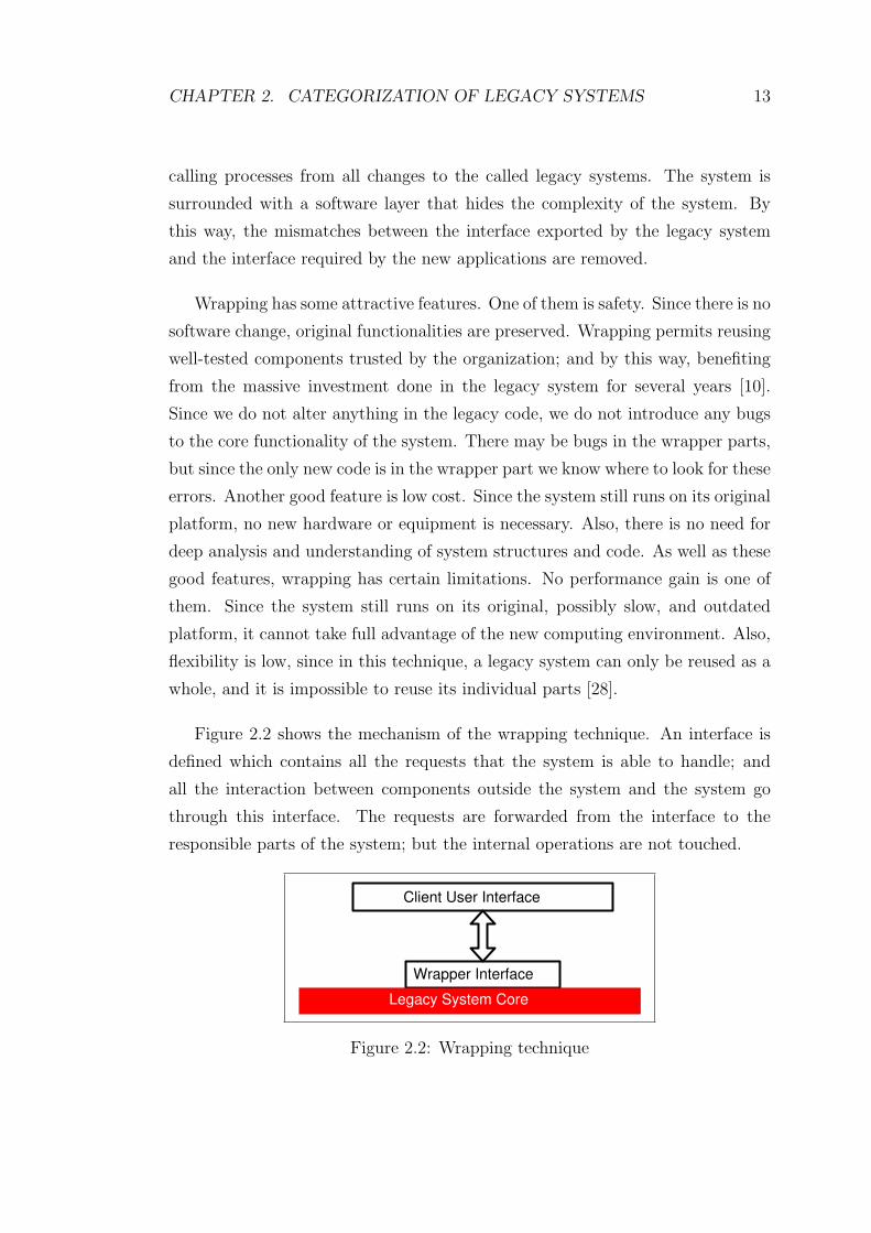
Figure 2.2 shows the mechanism of the wrapping technique. An interface is
defined which contains all the requests that the system is able to handle; and
all the interaction between components outside the system and the system go
through this interface. The requests are forwarded from the interface to the
responsible parts of the system; but the internal operations are not touched.
Client User Interface
Wrapper Interface
Legacy System Core
Figure 2.2: Wrapping technique

CHAPTER 2. CATEGORIZATION OF LEGACY SYSTEMS 14
2.3.2 Migration
Migration moves the legacy system to a more flexible environment that allows
the system to be easily maintained and adapted to new business requirements.
In migration, the system’s original functionality is retained, and the disruption
caused to the existing operational and business environment is as little as possible.
The methodology for migrating legacy code lies between a wrap and a full
rewrite. Migration is much more complex then wrapping, but if successful, it
offers greater long-term benefits. On the other hand, it aims to avoid a com-
plete redevelopment of the legacy system. If most of the legacy system must
be discarded, the developer will be facing a redevelopment project, not a migra-
tion project. Migration aims to reuse as much of the legacy system as possible,
including implementation, design, specification, and requirements [9].
The target system, which is the result of the migration process, runs in a
different computing environment. This may be a different programming language
or a completely new architecture and technology [9]. For example, a system
may be migrated from mainframe environment to a UNIX server; or procedural
COBOL code may be migrated to object-oriented technology.
2.3.3 Redevelopment
Redevelopment is the legacy system maintenance approach that leads to most im-
portant changes. It requires rewriting the existing code, and involves developing
a system from scratch.
Redevelopment requires a thorough understanding of the existing system and
thus involves many reengineering activities [9]. Reengineering is the examination
and modification of a system to reconstitute it in a new form and the subsequent
implementation of the new form. Reengineering consists of two stages: (1) reverse
engineering, and (2) forward engineering. Reverse engineering is the process of

CHAPTER 2. CATEGORIZATION OF LEGACY SYSTEMS 15
discovering software design and specification from source code. In reengineer-
ing, initially, the current program is reverse engineered to recover the high-level
abstraction or design of the software. The recovered design is then forward engi-
neered with a low level implementation of the high level abstraction. The result
is a new program with either the same functionality, or enhanced functionality
to meet new requirements.
The redevelopment of legacy systems is widely recognized as one of the most
significant challenges facing software engineers. Legacy systems are well-tested
and encapsulate considerable business expertise; but there is no guarantee that
the new system, which is the result of the redevelopment process, will be as robust
and functional as the old one. Redevelopment needs extensive testing of the new
system. Also, since the technology and the business requirements are constantly
changing, the developers may come across a situation where the new system no
longer meets the business needs when they have finished redeveloping the system.
2.4 Analysis of Legacy System Maintenance
Approaches
In this section, we define the possible legacy maintenance activities for each legacy
system type, as it is presented in the literature.
2.4.1 Wrapping
Wrapping only requires the knowledge of the external interfaces of the legacy
system. In wrapping, only the legacy interface is analyzed, inputs and outputs of
the system are examined; and legacy system internals are ignored. The system
is treated as a black box. For a successful wrapping, a good black-box model of
the existing source code must be available. The input and output routines of the
legacy code must be well defined. Since this technique doesn’t require insight on
the legacy system internals, it is suitable for both black box and white box legacy
CHAPTER 2. CATEGORIZATION OF LEGACY SYSTEMS 16
systems.
Wrapping may be applicable to mission critical systems, because they allow
an organization to benefit from the new technologies without having to interrupt
the operation of their mission critical legacy system [32].
If a legacy system does not function properly, wrapping the system cannot
be recommended. Wrappers are useful for gaining access to legacy code, not for
repairing it. So, wrapping is not applicable to terminally ill systems.
2.4.2 Migration
Legacy system migration process is divided into five phases [10]:
1. The first phase is the justification phase. Since the legacy system migration
process is an expensive procedure and carries a risk of failure, an intensive
study should be undertaken in order to be able to weigh the risks and
benefits of migrating the system, before taking any decision.
2. The second phase is called legacy system understanding phase. This phase
consists of the analysis and assessment of the legacy system to understand
its operations and interactions. Since a legacy system already meets some
of the business and user requirements demanded of the target system, poor
legacy system understanding can lead to incorrect target system require-
ment specifications and to failed migration projects [9]. For the success
of migration, it is essential that the functionalities of the legacy system,
and how it interacts with its domain must be understood. The issues of
understanding the source code of legacy applications, and understanding
the structure of legacy data are central to all migration projects. Typically,
at the beginning of the migration process, stock of all application artifacts
such as source code must be taken; a complete database analysis includ-
ing tables, views, indexes, procedures, and triggers, and data profiling is
required; and also, it is necessary to identify and map out the core business

CHAPTER 2. CATEGORIZATION OF LEGACY SYSTEMS 17
logic, to show the interrelationships of the code performing the application’s
business function.
3. The third phase is the target system development phase. This phase consists
of developing a target system according to the requirements specification
prepared in the legacy system understanding phase. The target system
must be fully operative, and functionally equivalent to the legacy system.
4. The fourth phase is the testing phase. Since in most cases the legacy system
is mission critical, target system outputs must be completely consistent with
those of the legacy system. So, testing activity takes the most time during
migration. Migration projects are often expected to add functionality to
justify the project’s expense and risk. If this is the case, the legacy system
should be migrated first, and, new functionality should be introduced to
the target system after the initial migration. Because, when functionality
is the same, engineers can directly compare outputs to determine the target
system’s validity, in the testing phase.
5. The last step is the migration phase, and it is concerned with the cutover
from the legacy system to the target system. Three different strategies [33]
have been proposed for this step:
• The first one is the cut-and-run strategy, which consists of cutting
over to the target system in a single step. This is unrealistic and risky
because the target system is untried and thus untrustworthy.
• The second strategy, which is called phased interoperability, is highly
complex. In this strategy, the cut over is performed in small, incremen-
tal steps, and each step replaces a few components of the legacy system
with corresponding target components. To be successful, legacy sys-
tem applications must be split into functionally separate modules, or
the data must be separated into portions that can be independently
migrated. But such a step-wise approach is difficult because of the
monolithic and unstructured nature of most legacy systems.
• The best is the last strategy, which is called parallel operations. In

CHAPTER 2. CATEGORIZATION OF LEGACY SYSTEMS 18
this strategy, the legacy system and the target system operate simul-
taneously, with both systems performing all operations. During this
period, the target system is continually tested; once it is fully tested,
the legacy system is retired.
As can be understood from the explanations of the phases of migration pro-
cess, in order to be able to apply migration to a system, information on the
internal structure of the system must be available; in other words, the legacy
system must be a white box system. Migration is not applicable to black box
legacy systems.
Different migration techniques, that are explained in [10], [11], [32], [44], and
[43], are examined below, according to their applicabilities to different categories
of legacy systems. Note that, the first three of the techniques must be considered
for the legacy systems which contain a database. We admit that not all of the
legacy systems have a database; there may be a legacy system which consists
only of Java code, for example. Hence, in Table 2.1, we do not focus on specific
techniques but the migration approach in general.
• Forward Migration (Database First) : Forward Migration involves the initial
migration of legacy data to a modern, probably relational Database Man-
agement System and then incrementally migrating the legacy applications
and interfaces. In this method, while legacy applications and interfaces are
being redeveloped, the legacy system remains operable. The interoperabil-
ity between the legacy and target systems is allowed, and provided by a
module known as Gateway. Forward Gateway enables the legacy applica-
tions to access the database environment in the target side of the migration
process. Here, the legacy system can remain operational while legacy ap-
plications and interfaces are rebuilt and migrated to the target system one
by one. When migration is complete, the gateway is no longer required
[32] [44]. The migration of legacy data may take a significant amount of
time during which the legacy system will be inaccessible; so, this method is
not applicable to mission critical systems [44]. This approach is applicable

CHAPTER 2. CATEGORIZATION OF LEGACY SYSTEMS 19
to legacy systems which are white box decomposable, and where a clean
interface to the legacy database service exists [32].
• Reverse Migration (Database Last Approach) : In this approach, legacy
applications are gradually migrated to the target platform while the legacy
database remains on the original platform. Legacy database migration is
the final process. As in Forward Migration, a gateway allows the interop-
erability between old and new systems. A reverse gateway enables target
applications to access the legacy data management environment [32] [44].
This method is not applicable to mission critical legacy systems because of
the unacceptability of the period of time during which the legacy system
will be shut down during the migration process. This approach is suitable
for white box decomposable legacy systems as is the case with Forward
Migration [32].
• Composite Database Approach : Here, the legacy and target information
systems are operated in parallel throughout the migration project. The old
legacy system and the target system form a composite information system
during the migration process. A combination of forward and reverse gate-
ways is used. A transaction coordinator is employed to provide consistency
between the legacy and target databases [32]. This approach eliminates the
need for a single large migration of legacy data during which the legacy
system is inaccessible, so it is not inapplicable to mission critical systems,
as Forward and Reverse Migration methods were [32].
• Chicken Little Strategy : In this method [11], the legacy system is migrated
in small incremental steps until the desired objective is reached. The re-
source allocation is small for each incremental step. If one of the steps fails,
only that step needs to be repeated, not the entire migration process. The
incremental steps are designed to be inexpensive so do not cause any prob-
lems with the management to be funded. The legacy and the target systems
operate in parallel during the migration process, and they are connected by
a gateway. This method is applicable to both white box decomposable, and
white box non-decomposable systems [32]. Also, it is applicable to mission
critical systems, because it takes into account that mission critical legacy

CHAPTER 2. CATEGORIZATION OF LEGACY SYSTEMS 20
systems cannot be out of operation for any significant amount of time,
and thus provides a mechanism for the legacy system to remain operable
throughout the migration process [10].
Figure 2.3 shows the mechanism of Chicken Little strategy. The gateway
maintains the interface that the legacy user interface (UI) expects of the
legacy system even though the system is being changed behind the scenes.
This transparency permits the developer to alter one part of the legacy IS
at a time. This capability is critical to the Chicken Little strategy. As the
target graphical user interface (GUI) is iteratively introduced, the gateway
makes transparent to the GUI and UI whether the legacy information sys-
tem or the target information system or both are supporting a particular
function. Hence, the gateway can insulate a component that is not being
changed (e.g., the UI) from changes that are being made (e.g., migrating
the legacy database to the target database). Legacy applications are grad-
ually rebuilt on the target platform. When the target system can perform
all the functionality of the legacy system, the legacy system can be retired.
UI GUI
Gateway
Legacy IS Target IS
Figure 2.3: Chicken Little strategy
• Butterfly Methodology : This method assumes that the target and legacy
systems need not interoperate during the migration process, eliminating
the need for gateways [10] [32] [44] [43]. It separates the target system
development and data migration phases. Using this methodology, the mi-
gration process is reversible prior to the cut-over phase; and migration can
be safely stopped. This method is applicable to mission critical systems

CHAPTER 2. CATEGORIZATION OF LEGACY SYSTEMS 21
as the Chicken Little Strategy, since the legacy system will remain in full
production during the migration process [44].
2.4.3 Redevelopment
The most widely researched and best-understood approach to redeveloping legacy
systems is the cold turkey approach [12]. In this approach, the legacy system is
replaced by a new system with the same or improved functionality, that is, the
system is completely rewritten. This is done in two phases: in the first phase, a
new set of requirements is constructed and some aspects of the existing design
such as overall architecture are identified and retained, using reverse engineering
and domain analysis techniques. Then in the second phase, the new system is
built using an appropriate software development methodology. It requires the
system to be shut down either during development or during replacement.
Unfortunately, for a high proportion of large legacy systems, this approach
is infeasible. Making such a huge change in a single step is rather risky, and
also, the downtime required for the cutover from the legacy system to the target
system is unacceptable for mission critical legacy systems [34]. So, this method is
applicable to legacy systems which are not mission critical, which are relatively
small in size, and which have a well defined stable functionality [32].
Development of such massive systems takes years, so business requirements
may change during the redevelopment project itself. Then unintended business
processes will have to be added to come up with the changing business require-
ments and this will increase the risk of failure. Some other factors working against
cold turkey approach are listed in [11] as follows: In most of the organizations,
management rarely approves a major expenditure if the only result is lower main-
tenance costs, instead of additional business functionality. So, in order to get the
required sources for the redevelopment process, a better system and additional
features must be promised. Also, the redevelopment process generally takes longer
than planned and ends up costing much more than anticipated. While the legacy
redevelopment proceeds, some changes occur in the business processes that the

CHAPTER 2. CATEGORIZATION OF LEGACY SYSTEMS 22
target system will support; and this leads to significant changes in the require-
ments of the target system during the redevelopment process, increasing the risk
of failure.
2.5 Legacy System Design Space
Given the different types of legacy systems, it is not trivial to identify the ap-
propriate maintenance approach for a legacy system type. To provide a more
systematic interpretation on legacy systems, we utilize design space modelling
[38] to define the design space of legacy systems. We can model a legacy system
as follows: Legacy System = (Criticality, Health, Accessibility)
Hereby a legacy system is modelled as a Cartesian product of the vectors
(dimensions) criticality, health, and accessibility. Each dimension includes its
own set of values (coordinates). Criticality dimension includes the coordinates
mission critical and replaceable; health state dimension includes the coordinates
healthy, ill and terminally ill ; and finally accessibility dimension includes the
coordinates black box, white box non-decomposable and white box decomposable.
In this way all the set of alternative legacy systems can be represented. Given
the three categorization dimensions, we could have 2(for criticality) x 3(for health
state) x 3(for accessibility) = 18 possible kind of legacy systems. In general legacy
systems which are not business critical are usually not considered for maintenance
activities. For this, we will consider only mission critical legacy systems which
will lead to 3x3=9 possible kinds of legacy systems.
In finding the right evolution approach for a legacy system, we should first
characterize the corresponding legacy system, and then identify the necessary
legacy evolution technique. The kind of evolution approach usually depends on
all of the three legacy categorization criteria. For example, a legacy system
could be mission critical because it is important from a business perspective, ill
since it has deteriorated and white box decomposable because of a clear accessible
structure. In this case, by looking at Table 2.1, we can say that both wrapping

CHAPTER 2. CATEGORIZATION OF LEGACY SYSTEMS 23
and migration may be applicable for maintaining the legacy system.
Health State Accessibility Maintenance Approach1 Healthy Black box Wrapping2 Healthy White box decomposable Wrapping3 Healthy White box non decomposable Wrapping4 Ill Black box Wrapping5 Ill White box decomposable Wrapping,Migration6 Ill White box non decomposable Wrapping,Migration7 Terminally ill Black box Redevelopment8 Terminally ill White box decomposable Redevelopment9 Terminally ill White box non decomposable Redevelopment
Table 2.1: Legacy system categories vs. evolution approaches
2.6 Summary
In this chapter we have defined the legacy system categories according to the
criticality, health state and accessibility criteria. Then we have explained the
three legacy maintenance approaches wrapping, migration and redevelopment,
and evaluated these approaches for the legacy system categories we have defined.
As a result, we have defined appropriate legacy maintenance techniques for each
legacy system category. These information is presented in Table 2.1.
Chapter 3
Crosscutting Concerns in Legacy
Systems
In this chapter we explain the so-called crosscutting concerns that cut across the
natural units of modularity. These concerns cannot be specified in a single module
and they tend to be scattered over the whole code. In Section 3.1, we describe
an example case, Drugstore Information System, which is implemented in Java
and that we consider as legacy code for illustration purposes. The example case
is analyzed using evolution scenarios, which are described in Section 3.2. Finally,
in Section 3.3 we describe the problem statement.
3.1 Case Study: Drugstore Information System
The Drugstore Information System (DIS) is an information system for supporting
the retail of medicine. It is implemented in Java.
DIS consists mainly of the classes Drugstore, Drug, Doctor, Patient, Sale and
Prescription. In this system, a drugstore sells drugs to patients. Some of the
drugs are only sold to a patient having a prescription, while others can be sold to
every patient. Also drugs have some other characteristics, such as expiration date,
24
CHAPTER 3. CROSSCUTTING CONCERNS IN LEGACY SYSTEMS 25
contained active elements, and critical level, which represents the least amount
that must be in the stock of a drugstore.
A doctor in our system has patients. When a patient visits a doctor, the
doctor examines the patient and gives a prescription.
Patients may be a member of a Turkish social security association (SSA) such
as SSK, Bag Kur, or Emekli Sandigi. This allows the patients to pay only a
certain amount of the payment when buying drugs from a drugstore. In this
situation, the drugstore gets the rest of the payment from the associated social
security association.
Figure 3.1 shows the class diagram of DIS. Most important classes are briefly
explained below.
Doctor is a person qualified to give a prescription to a patient.
Drug contains the properties of drugs, like active elements in it, price, expi-
ration date, sold with/without prescription, critical level, stock level, etc.
Drugstore is a store that sells drugs to patients with or without prescription,
if the drugs they want to buy are available.
Patient is a person that buys drugs from a drugstore with or without pre-
scription, and that goes to doctor for taking prescription.
Prescription is a document given to a patient by a doctor and it specifies
properties such as prescription id, date, names and amount of drugs prescribed,
name of patient, name of doctor, social security association.
Sale contains the information of the sales of a drugstore, such as the patient
name, drug names, and if with prescription, doctor name.

CHAPTER 3. CROSSCUTTING CONCERNS IN LEGACY SYSTEMS 26
Figure 3.1: Class diagram of Drugstore Information System
3.2 Enhancing the Legacy System
Scenarios have been used in various ways like, for requirements elicitation [15],
for analysis of software architecture [19], etc. In this section, we use scenarios
for analyzing the enhancement of DIS with new concerns. The scenarios for
enhancing the DIS are explained below.
Scenario 1. Adding logging concern
The system has a new requirement that, doctors, drugstores and patients
must keep track of their operations; i.e. the operations of the classes Doctor,
Drugstore and Patient must be logged. For example, a doctor keeps information
of the patients, drugstore keeps the information on the drugs and the sales, and
also a patient keeps the information of prescriptions given to him. The logs must
be written to a file.

CHAPTER 3. CROSSCUTTING CONCERNS IN LEGACY SYSTEMS 27
Scenario 2. Updating exception handling concern
In DIS, whenever a public method call returns throwing an exception, an error
message is given. Suppose that there is a new requirement that the way of excep-
tion handling must be updated in a way that the program must be terminated if
a public method call returns throwing an exception. In order to implement this
update it is required to change the code in multiple places in the system. Because
the exception handling concern is scattered over the whole system.
Scenario 3. Updating allergy checking concern
Patients may have allergies to some active elements contained in drugs. In
DIS, the allergies of the patient are taken into account by the doctors and drug-
stores when giving a prescription and selling a drug to a patient. That is, if the
patient has allergy to any of the active elements contained in the drug he/she
wants to buy, the drugstore does not sell that drug to him/her. Or a doctor
checks if the patient has allergy to any of the active elements of the drug before
giving prescription to the patient for that drug. If he/she has, the doctor does
not give prescription. Suppose that an update is required for this allergy checking
concern, such that, if the patient is allergic to the drug he/she wants to buy, the
drugstore will find a drug with equal effect and sell it to the patient. Also, the
doctor will prescribe a drug which has equal effect to a patient, if the patient is
allergic to the drug he/she has initially prescribed.
Scenario 4. Removing tracing code
In order to increase the visibility of the internal workings of the program for
simplifying debugging, trace statements were added at specified method calls.
Suppose that the debugging is complete, and these trace statements need to be
removed from the DIS code.
Scenario 5. Removing security concern
In DIS, doctors and druggists must be registered to the system, and provide

CHAPTER 3. CROSSCUTTING CONCERNS IN LEGACY SYSTEMS 28
valid ID-password information in order to use the system. Suppose that the log
in operation is no longer needed, and needs to be removed.
3.3 Problem Statement
In this section we analyze the above scenarios, and explain the problem with
these scenarios.
• Adding new concerns
In Scenario 1, the expectation is the addition of a new concern to the
system. The logging concern is related to Doctor, Patient and Drugstore
classes. Hence, in order to add this concern, we must change the code of
some methods of multiple classes, which is a time consuming task. Also,
when we add this concern to the related methods of the related classes, it
will not be related to the main concern of the methods it is added to; but
it will be tangled with their main logic. As a result, it will get harder to
understand these methods.
• Updating existing concerns
In Scenarios 2 and 3, it is required to update an existing concern. Im-
plementing the requirements are difficult, because the concerns of both of
the scenarios are scattered over the whole system. Therefore the update
needs to be done in several places. First the points to be updated must
be identified. Then the code must be changed in these points in order to
implement the update. In order to realize Scenario 2, the points where
an exception is handled must be identified first, and then the code must
be changed to terminate the program at these points. On the other hand,
for realizing Scenario 3, the related methods of both the Doctor and the
Drugstore classes must be changed. This is not only a tedious work, but
also error-prone, since not managing to define all the points where the code
must be changed results in the wrong way of working of the program.

CHAPTER 3. CROSSCUTTING CONCERNS IN LEGACY SYSTEMS 29
• Removing existing concerns
In Scenario 4 and 5 , the expectation is the removal of an existing concern.
In Scenario 4, the involved concern is the tracing concern, which crosscuts
a large part of the system. As in the update of this type of concerns,
the removal is tiring. Removing the tracing code completely results in the
waste of the considerable effort spent for figuring out the trace points, and
adding print statements to these points. On the other hand, commenting
out the tracing code may result in bad looking code, and confusion of the
statements of one kind of debugging with the statements of another kind
[3]. On the other hand, the removal of the security concern in Scenario 5
is also difficult, since the removal of the code must be performed in two
different places.
Above scenarios are in general crosscutting. Dealing with these types of sce-
narios is difficult, because the system must be changed at many places in order to
realize these scenarios. The concerns they are related to are spread throughout
the program in an undisciplined way, and cut across the natural units of mod-
ularity. If not appropriately coped with, the addition, update and removal of
crosscutting concerns result in code tangling, which means multiple concerns are
interleaved in a single module; and code scattering, which means a single concern
affects multiple modules.
To the best of our knowledge, existing legacy maintenance approaches do
not provide mechanisms to cope with crosscutting concerns. This increases the
complexity and reduces the maintainability of the system even further. The
system must be extended to cope with the crosscutting concerns.

Chapter 4
Aspect-Oriented Software
Development
In this chapter, we give a background on Aspect-Oriented Software Development
(AOSD). We first explain the basics of Aspect-Oriented Programming (AOP)
in Section 4.1, and then the basic AOP approaches, AspectJ in Section 4.3.1,
Composition Filters in Section 4.3.2, HyperJ in Section 4.3.3 and DJ in Section
4.3.4.
4.1 Introduction
One of the most important principles in software engineering for coping with
complexity and achieving quality software is the separation of concerns principle.
This principle states that a given design problem involves different kinds of con-
cerns, which should be identified and separated in different modules; and tries
to separate the basic algorithm from special purpose concerns. It minimizes and
clarifies the dependencies between concerns at the conceptual and implementation
level.
The history of software development has experienced an evolution of different
30
CHAPTER 4. ASPECT-ORIENTED SOFTWARE DEVELOPMENT 31
programming languages and design paradigms that have provided useful modular-
ity mechanisms. Object-Oriented Programming (OOP) has been the mainstream
over the last decade, and has almost completely replaced the procedural approach.
Object orientation has the central idea that each concern of a software system
should be implemented as a separate module, and a software system can be seen
as being built of a collection of discrete classes each implementing a different
concern. In OOP, each class has a well defined task and clearly defined respon-
sibilities. They altogether achieve the application’s overall goal by collaboration
[40].
Software development techniques used, including procedural programming
and OOP, have made significant improvements in modularity [20]. However,
as it is experienced in practice and generally acknowledged by researchers, it ap-
pears that these approaches are inherently unable to modularize all concerns of
complex software systems. There are some concerns, such as synchronization,
recovery and logging that tend to be more systemic, and crosscut a broader set
of modules. They cannot be easily specified in a single module, they need to
be addressed in many modules. For the OOP case, there are parts of a system
that cannot be viewed as a responsibility of only one class, because they affect
many classes and crosscut the complete system. The code to handle these parts
must be added to each class separately, resulting in the violation of separation
of concerns principle. Hence, even OOP techniques are not sufficient to clearly
capture the concerns that inherently crosscut the modularity of the rest of the
implementation [20]. If these crosscutting concerns are not appropriately coped
with, their implementation is scattered throughout the whole system, and the
code to handle these concerns is mixed in with the core logic of a huge number of
modules, resulting in tangled code. These increase complexity and reduce several
quality factors of software, such as adaptability, maintainability and reusability.
AOP has been proposed to deal with the problem of improving separation
of concerns in software. It is a technique that builds on previous technologies
including procedural programming and OOP, and provides better separation of
concerns by explicitly considering crosscutting concerns as well. AOP makes it
possible to implement crosscutting concerns in a modular way, and achieve the
CHAPTER 4. ASPECT-ORIENTED SOFTWARE DEVELOPMENT 32
usual benefits of improved modularity: simpler code that is easier to develop
and maintain, and has greater potential for reuse [20]. Using AOP, one can
implement individual concerns in a loosely-coupled fashion, and combine these
implementations to form the final system. AOP provides explicit abstractions for
representing crosscutting concerns, such as aspects; and for composing these into
programs, such as aspect weaving.
4.2 Basics of AOP
The AOP based implementation of an application consists of: (1) a component
language with which to program components (components are properties which
can be cleanly encapsulated in a generalized procedure); (2) one or more as-
pect languages with which to program the aspects; (3) an aspect weaver for the
combined languages; (4) a component program that implements the components
using the component language; (5) one or more aspect programs that implement
the aspects using the aspect languages. The aspect weaver corresponds to the
compiler (or interpreter) in the object oriented implementation. It accepts the
component and aspect programs as input, and emits a program as output [21].
Development steps of AOP are explained in [22] as follows:
1. Aspectual decomposition: In this step, requirements are decomposed in or-
der to identify crosscutting system level concerns and module level common
concerns.
2. Concern implementation: In this step, each concern is implemented sepa-
rately.
3. Aspectual recomposition: In this step, an aspect integrator specifies recom-
position rules by creating modularization units which are called aspects.
Recomposition process which is also known as weaving, or integrating, uses
recomposition rules to compose the final system.
CHAPTER 4. ASPECT-ORIENTED SOFTWARE DEVELOPMENT 33
AOP helps to overcome code tangling and code scattering problems. It also
brings some other advantages [22]:
• Even in the presence of crosscutting concerns, AOP implements a system
in a modularized way, by addressing each concern separately with minimal
coupling.
• It is easy to evolve systems by AOP. Newer functionalities can be added to
a system easily, by creating new aspects.
• With AOP, an architect can delay making design decisions for future re-
quirements, since he/she can implement those as separate aspects.
AOP has also some disadvantages. For example, there are few experiments
about the AOP, hence the technique is not mature yet. Also, AOP approaches
like AspectJ are language dependent. Furthermore, less focus has been put on
the design of aspect-oriented systems.
4.3 AOSD Approaches
AOP is a concept and it is not bound to a certain programming language, or a pro-
gramming paradigm. Several aspect-oriented approaches have been introduced
providing different solutions to the problems caused by crosscutting concerns. In
particular, we will consider the following approaches:
• AspectJ, developed by XEROX PARC
• Composition Filters, developed by University of Twente
• HyperJ, developed by IBM
• DJ, developed by Northeastern University.
CHAPTER 4. ASPECT-ORIENTED SOFTWARE DEVELOPMENT 34
4.3.1 AspectJ
AspectJ [3] [20] is a simple and practical aspect-oriented extension to Java. As-
pectJ uses Java as the language for implementing individual concerns, and it
specifies extensions to Java for the weaving rules. Every valid Java program is
also a valid AspectJ program. The AspectJ compiler, which is called weaver,
produces class files that comply with Java byte code specification, hence any
compliant Java virtual machine can interpret the produced class files. By choos-
ing Java as the base language, AspectJ passes on all the benefits of Java, and
makes it easy for Java programmers to use it [22].
AspectJ depends on a powerful set of constructs; joinpoints, pointcuts, advice,
introduction, and aspects. Below, these constructs are examined one by one.
Joinpoints
The joinpoint model is a critical element in the design of any aspect oriented
language. A joinpoint is a well-defined point in a program’s execution. Examples
of joinpoints include calls to a method, a loop’s beginning, etc. A joinpoint is
first reached just before the action described begins executing, and control passes
back through the joinpoint when the action described returns. AspectJ provides
the following kinds of joinpoints:
• Method call and constructor call: a method or constructor is called.
• Method call reception and constructor call reception: an object receives a
method or constructor call.
• Method execution and constructor execution: an individual method or a
constructor is invoked.
• Field get: a field of an object, class or interface is read.
• Field set: a field of an object or class is set.
• Exception handler execution: an exception handler is invoked.

CHAPTER 4. ASPECT-ORIENTED SOFTWARE DEVELOPMENT 35
• Class initialization: static initializers for a class, if any, are run.
• Object initialization: dynamic initializers for a class, if any, are run during
object creation.
Only a few kinds of these joinpoints suffice for many programs. thisJoinPoint
is a special variable which is bound, within advice bodies, to an object that
describes the current joinpoint.
Pointcuts
Pointcuts identify collections of certain joinpoints in the program flow. As-
pectJ includes several primitive pointcut designators [22]. The following are some
examples:
• Receptions(void Class1.method1(String)): Matches all method call reception
joinpoints at which the Java signature of the method call is void
Class1.method1(String). Represents call to method1 in class Class1, taking
a String argument.
• Call(int Class1.method1(..)): Represents call to method1 in class Class1, taking
any arguments, with int return type.
• Call(* Class1.method1(..)): Represents call to method1 in class Class1, taking
any arguments, with any return type.
• Call(int Class1.method1*(..)): Represents call to any method with name start-
ing with method1 in class Class1.
• Call(Class1.new(..)): Represents call to Class1 ’s constructor, with any argu-
ments.
• Execution(void Class1.method1(double)): Represents execution of method1 in
Class1, taking a double argument, returning void.
• Set(int Class1.field1): Represents execution of write access to field field1 of
type int, in Class1.

CHAPTER 4. ASPECT-ORIENTED SOFTWARE DEVELOPMENT 36
• Get(String Class1.field1): Represents execution of read access to field field1 of
type String, in Class1.
• InstanceOf(Class1): Matches joinpoints of any kind, at which, the currently
executing object is of type Class1.
• Handler(Exception1): Represents evolution of catch block handling exception
types with the name Exception1.
• Within(Class1): Matches joinpoints of any kind inside Class1’s lexical scope.
• Cflow(call(* Class1.method1(..))): Matches all the joinpoints in the control
flow(the flow of program instructions) of the call to any method1 in Class1,
including call to the specified method itself.
• Target(Class1): Matches all the joinpoints where, the object on which the
method is called, is of type Class1.
• Args(String): Matches all the joinpoints, where there is only one argument,
and it is of type String.
Programmers can compose these primitive pointcuts to define user-defined
pointcut designators. User-defined pointcut designators are defined within the
Pointcut declaration. Pointcuts can be combined using &&, ‖, and ! operators.
An example pointcut declaration is shown below.
e.g. Pointcut myPointcut():
receptions(void Class1.method1(int,int)) ‖receptions(void Class2.method2(double));
Advice
Advice is a method like mechanism that declares the code to be executed when
reaching the joinpoints in a pointcut. AspectJ provides different ways to associate
additional code to the joinpoints, by using different kinds of advice: Before advice
runs when a joinpoint is reached, and before the computation associated with the
joinpoint proceeds. After advice runs after the computation associated with the
CHAPTER 4. ASPECT-ORIENTED SOFTWARE DEVELOPMENT 37
joinpoint finishes. Around advice runs when a joinpoint is reached, and it has
explicit control over whether the computation associated with the joinpoint is
allowed to run.
e.g. before(): myPointcut() { System.out.println(”Entering ”+thisJoinPoint); }
e.g. after(): call(int Class1.method1(String)){ System.out.println(”After executing
method1...”);}
e.g. void around(): Class1.method1(){ if (enabled) proceed();}
Introduction
AspectJ provides the introduction mechanism for modifying classes and their
hierarchy. Introduction may add new members to classes, and alter the inheri-
tance relationship between classes. Unlike advice that operates dynamically, at
run time, introduction operates statically, at compile time. In the example below,
the aspect Aspect1 introduces an instance field of type Vector, into class Class1.
e.g. aspect Aspect1{private Vector Class1.myVector=new Vector();
....
}
Aspects
Aspects are modular units of crosscutting implementation. AspectJ’s aspects
correspond to Java’s classes. An aspect can contain methods and fields, extend
other classes or aspects, and implement interfaces. However, we cannot create an
object for an aspect using new [22].
Aspects can be divided into two categories as development aspects and pro-
duction aspects. Development aspects are used during development of Java ap-
plications. They facilitate debugging, tracing, testing work. Production aspects
implement crosscutting functionality common in Java applications. They tend to
add functionality to an application rather than only adding more visibility of the

CHAPTER 4. ASPECT-ORIENTED SOFTWARE DEVELOPMENT 38
internals of a program.
Some Additional Notes
AspectJ allows classes to declare pointcuts. However, AspectJ doesn’t allow
classes to contain advices; only aspects can contain advices. Any aspect and
any pointcut can be declared as abstract. Abstract pointcuts act in the way a
class’s abstract methods do. They let you defer the implementation details to
the derived aspects. A concrete aspect extending an abstract aspect can provide
concrete definitions of abstract pointcuts [22].
Using AspectJ results in clean, well-modularized implementations of cross-
cutting concerns. When written as an aspect, the structure of a crosscutting
concern is explicit and easy to understand. Aspects are highly modular, making
it possible to develop plug and play implementations of crosscutting functional-
ity. For example, consider a tracing aspect which prints messages before certain
operations. Here, the tracing functionality is modularized, that is, the code is
localized, and has a clear interface with the rest of the system. In order to change
the set of method calls that are traced, the only thing to be done is editing the
tracing aspect and recompiling. The individual methods traced do not need to be
edited. Let’s consider another example, debugging. When debugging, program-
mers invest a considerable effort to determine a good set of trace points to use
for looking for a particular kind of a problem. When debugging is complete, it’s
frustrating to have to lose that investment by deleting the trace statements from
the code. Commenting them out, as an other alternative, makes the code look
bad. However, programmers don’t experience these problems when implementing
debugging functionality with AspectJ. The thing to be done is to write an aspect
specifically for that tracing mode, and remove the aspect from the compilation
when it’s not needed. Just as with these development aspects, the functionality
provided by production aspects may need to be removed from the system, either
because the functionality is no longer needed at all, or because it’s not needed in
certain configurations of a system. This is easy to do because the functionality
is modularized in a single aspect [3].

CHAPTER 4. ASPECT-ORIENTED SOFTWARE DEVELOPMENT 39
4.3.2 Composition Filters
Basic Structure
Composition Filters (CF) is an AOP approach, in which, different aspects
are expressed in filters as declarative and orthogonal message transformation
specifications [37]. CF model is a modular extension to the conventional object
oriented model, and the aim of this model is to improve the expression power
of object oriented model without having to modify the underlying structure. In
CF model, the behaviors of objects are enhanced through the manipulation of
incoming and outgoing messages. Messages are captured and manipulated by the
filters that are attached to the objects. Each individual filter is responsible for a
specific manipulation, and the filters together compose the behavior of an object
[7].
A CF object consists of two parts: an interface part and an implementation
part. The interface part consists of input and output filters, and deals with incom-
ing and outgoing messages. Implementation part, which is also referred to as the
inner object, contains operation definitions, variable declarations and definition
of conditions. Figure 4.1, taken from [7], shows the components of the CF model.
Figure 4.1: Components of the CF model [7]

CHAPTER 4. ASPECT-ORIENTED SOFTWARE DEVELOPMENT 40
Message filtering mechanism
Input filters specify conditions for message acceptance or rejection, and de-
termine the subsequent action; on the other hand, output filters handle outgoing
messages. Each filter is declared as an instance of an arbitrary filter class. Each
filter can either accept or reject a message, depending on the semantics of ac-
ceptance or rejection associated with that type of filter. An arbitrary number
of filters may be defined for an object, and they are defined in an ordered set.
When a message is received by an object, it is reified, that means, a first-class
representation of the message is created. The reified message passes through all
the filters in the order they are defined. At the end, the message is either re-
jected; or dispatched, that is, activated again or delegated to another object. A
message itself contains information that determines how it should be dispatched.
For input filters, when a filter causes a message to be dispatched, this triggers
the execution of a method. For output filters, when a filter causes a message to
be dispatched, the message is submitted to the target object.
Filter specification and message evaluation
The structure of a filter specification is explained in [8], using the template
shown in Figure 4.2:
aFilterName : aFilterClass = { aCond1 => aTarget1.aSelector1, aCond2 => aTarget2.aSelector2, …};
The first filter element The second filter element
Filter initialization expression Filter declaration
Figure 4.2: Structure of a filter specification
In this template, aFilterName denotes the name of the filter, and aFilterClass
denotes the Filter class that the filter with name aFilterName is an instance of.
The filter elements, in the filter initialization expression, define specific conditions
for accepting particular sets of messages. A filter element consists of a condition
identifier and a target-selector pair. The evaluation of a filter element consists of
two stages:
CHAPTER 4. ASPECT-ORIENTED SOFTWARE DEVELOPMENT 41
• Condition evaluation stage: In this stage, the condition identifier is evalu-
ated. If it evaluates to True, the next step will be carried out; otherwise,
the filter element is skipped.
• Matching stage: In this stage, the selector of the received message is
matched with the selector specified by the filter element. If the match
is successful, then the target specified by the filter element is bound to the
message, and the message is accepted by the filter. If the match operation
fails, the filter element is skipped, and message will be checked against the
next filter element.
If the evaluation of none of the filter elements becomes successful, then the
message is rejected by the filter.
The following are some extra features of the basic filter specification mecha-
nism [8]:
• If no condition is explicitly specified in a filter element, the condition iden-
tifier is assumed to be True.
• If the character “*” is used in the target-selector pair, this denotes a don’t
care condition.
• If the target is omitted in the target-selector pair, the target is assumed to
be the pseudo-variable self.
• Several filter elements can be combined together to shorten filter expres-
sions. For example, when a single condition corresponds to several target-
selector pairs, the shorthand notation
condition1=>aTarget1.aSelector1,aTarget2.aSelector2
can be used instead of the notation
condition1=>aTarget1.aSelector1,condition1=>aTarget2.aSelector2.
Also, when several conditions correspond to a single target-selector pair,
the shorthand notation
CHAPTER 4. ASPECT-ORIENTED SOFTWARE DEVELOPMENT 42
condition1,condition2=>aTarget1.aSelector1
can be used instead of the notation
condition1=>aTarget1.aSelector1, condition2=>aTarget1.aSelector1.
• The implication operator “=>” has a counterpart, expressed as “∼>”.
They have opposite meanings. “=>” means that if the condition identifier
evaluates to True and the message matches on the target-selector pair, the
filter element will accept the message. Just the opposite, “∼>” means that
if the condition identifier evaluates to True and the message matches on
the target-selector pair, the filter element will reject the message.
Message evaluation is explained in [5] with the help of Figure 4.3. The example
consists of three filters. A received message M has to pass through all the filters
in order to be dispatched successfully. Here, the structure of filter elements is a
little bit different from the structure explained in [8], and consists of three parts.
The condition part is the same with the condition identifier explained before, and
it specifies the necessary condition to be fulfilled in order to continue evaluating
a filter element. The matching part specifies a pattern against which the message
will be matched. The substituting part specifies the pattern, with which, the
message can be replaced. Both the matching and substituting parts consist of
target-selector pairs.
In Filter A, the first filter element is skipped because the selector of the first
filter element doesn’t match with the selector of the message. For the second
filter element, this matching is successful and there is no restriction for the target
part. Hence, the message is accepted by the filter, and proceeds to the next filter.
In Filter B, the first filter element is skipped because the selectors and targets
don’t match. The selector and target matchings are successful for both the second
and third filter elements, but the message matches the second filter element, due
to the left-to-right ordering. Then the message proceeds to the third filter.
In Filter C, the first filter element is skipped again, because it doesn’t match.
The second filter element is also skipped, because it has a condition False. For
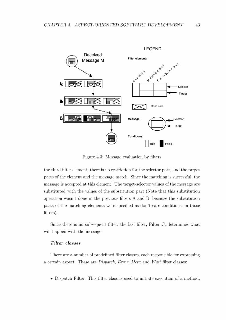
CHAPTER 4. ASPECT-ORIENTED SOFTWARE DEVELOPMENT 43
LEGEND:
C o
n d
i t i o
n
M a
t c h
i n g
p a r
t
S u b s
t i t u
t i o n
p a
r t
Selector
Target
Don't care
Filter element:
Message: Selector
Target
Conditions:
True False
Received
Message M
Figure 4.3: Message evaluation by filters
the third filter element, there is no restriction for the selector part, and the target
parts of the element and the message match. Since the matching is successful, the
message is accepted at this element. The target-selector values of the message are
substituted with the values of the substitution part (Note that this substitution
operation wasn’t done in the previous filters A and B, because the substitution
parts of the matching elements were specified as don’t care conditions, in those
filters).
Since there is no subsequent filter, the last filter, Filter C, determines what
will happen with the message.
Filter classes
There are a number of predefined filter classes, each responsible for expressing
a certain aspect. These are Dispatch, Error, Meta and Wait filter classes:
• Dispatch Filter: This filter class is used to initiate execution of a method,

CHAPTER 4. ASPECT-ORIENTED SOFTWARE DEVELOPMENT 44
if the message successfully passes it. If a filter, which is an instance of
Dispatch Filter accepts the received message, then the message is executed.
• Error Filter: This filter class is used for the selection and rejection of mes-
sages only. If a message is accepted by a filter, which is an instance of Error
Filter, the message proceeds to the next filter. Otherwise (if the message
is rejected by the filter), the filter raises an error condition and this causes
the abortion of the received message [8].
• Meta Filter: Meta filter is used to reify a message. To reify a message
means to make an object of the message. If the received message matches,
it is reified. The resulting object is sent as the argument of a newly created
message, with a target-selector pair as specified by the second part of the
filter element. If the received message doesn’t match, the filter rejects the
message, and no message reification is done.
• Wait Filter: This filter type is used to express synchronization. If a filter
is an instance of Wait Filter, it performs synchronization of messages by
queuing all messages as long as they cannot match with any of the filter
elements. If a Wait filter matches a message, then the message is forwarded
to the next filter. Otherwise, the message is queued until it can be accepted.
New filter types can be introduced, provided that they fulfil a number of
requirements. For example, in [4], Aksit et al. introduced the RealTime Filter,
which can be used to express the timing constraints on message executions. An
input filter of type RealTime is used to affect the timing attribute of the message
when corresponding message matches with the filter. If the message doesn’t
match with the filter, then it will pass to the next filter without receiving the
timing attribute.
Example Case: Email System
CF model is introduced in order to cope with the problem of reusing and
extending software with certain concerns, such as adding multiple views, history
sensitive behavior, synchronization, etc. Conventional OOP techniques cannot

CHAPTER 4. ASPECT-ORIENTED SOFTWARE DEVELOPMENT 45
deal with such extensions without unnecessary redefinitions, which lead to com-
position anomalies. In object orientation, composition of concerns is realized in
two different ways; either through aggregation, or through inheritance. In [7], it is
shown that neither aggregation based composition nor inheritance based compo-
sition can adequately express certain aspects of evolving software, with the help of
an example. A simple mail system is presented; and, aggregation and inheritance
mechanisms are applied in order to realize a change case. In each evolution step
in the change case, certain aspects are added to existing classes. The concerns,
that are addressed, are adding multiple views, view partitioning, view extension,
history sensitive behavior, and synchronization to multiple classes. The appli-
cation of both aggregation and inheritance mechanisms required a considerable
amount of method redefinitions. Here, we will look at the discussion for the first
evolution step: adding multiple views to the mail system.
Figure 4.4: Class diagram of the Mail System
Figure 4.4 shows the class diagram of the simple Mail System presented in
[37] [7]. Class Email represents the electronic messages sent in this system, and
provides methods for defining, delivering and reading mails. In the current im-
plementation of class Email, any client object is allowed to access the contents
of a mail. In the first evolution step, the class Email is specialized into class
USViewMail (User/System-View), and access to its methods is restricted based
on the class of the client object. Execution of the methods putOriginator(), pu-
tReceiver(), putContents(), getContents(), send() and reply() is allowed if the

CHAPTER 4. ASPECT-ORIENTED SOFTWARE DEVELOPMENT 46
client is of User type. Execution of the methods approve(), putRoute(), and de-
liver() is allowed if the client is of System type. There are no restrictions for the
execution of other methods.
In the following, realization of the change case by conventional OOP tech-
nologies (Aggregation-Inheritance) and by CF approach, is examined.
1. Aggregation-based composition
In this strategy, the USViewMail object encapsulates an instance of class
Email. The method implementations in class Email are reused by invoking
the appropriate method in the encapsulated Email object; but additional
code must be inserted for the methods that require a view constraint to be
checked. For example, the following pseudocode shows the implementation
of the method approve():
USViewMail :: approve()
if self.systemView() //returns true if client is of system type
then return imp.approve()
else self.viewError();
Figure 4.5 shows the aggregation-based composition of multiple views. As
can be seen from the figure, aggregation-based composition strategy requires
the redefinition of all methods of class Email, in class USViewMail.
Figure 4.5: Aggregation-based composition of multiple views

CHAPTER 4. ASPECT-ORIENTED SOFTWARE DEVELOPMENT 47
2. Inheritance-based composition
In this strategy, class USViewMail inherits from class Email ; and method
implementations in class Email are reused through super calls. View check-
ing is implemented for view constrained methods, as the same with the
previous strategy. Only those methods that require view checking have to
be redefined, other methods can be inherited from the super class. For ex-
ample, the pseudocode for the implementation of the method approve() is
as follows:
USViewMail :: approve()
if self.systemView() //returns true if client is of system type
then return super.approve()
else self.viewError();
Inheritance-based composition strategy is shown in Figure 4.6.
Figure 4.6: Inheritance-based composition of multiple views
3. Evaluation
The aggregation-based composition strategy requires 16 method redefini-
tions:
• 9 redefinitions for view checking and forwarding
• 5 redefinitions for forwarding only
• 2 redefinitions for implementing the views.
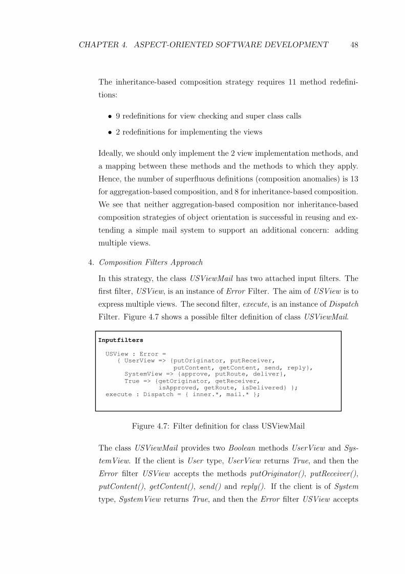
CHAPTER 4. ASPECT-ORIENTED SOFTWARE DEVELOPMENT 48
The inheritance-based composition strategy requires 11 method redefini-
tions:
• 9 redefinitions for view checking and super class calls
• 2 redefinitions for implementing the views
Ideally, we should only implement the 2 view implementation methods, and
a mapping between these methods and the methods to which they apply.
Hence, the number of superfluous definitions (composition anomalies) is 13
for aggregation-based composition, and 8 for inheritance-based composition.
We see that neither aggregation-based composition nor inheritance-based
composition strategies of object orientation is successful in reusing and ex-
tending a simple mail system to support an additional concern: adding
multiple views.
4. Composition Filters Approach
In this strategy, the class USViewMail has two attached input filters. The
first filter, USView, is an instance of Error Filter. The aim of USView is to
express multiple views. The second filter, execute, is an instance of Dispatch
Filter. Figure 4.7 shows a possible filter definition of class USViewMail.
Inputfilters
USView : Error =
{ UserView => {putOriginator, putReceiver,
putContent, getContent, send, reply}, SystemView => {approve, putRoute, deliver},
True => {getOriginator, getReceiver,
isApproved, getRoute, isDelivered} };
execute : Dispatch = { inner.*, mail.* };
Figure 4.7: Filter definition for class USViewMail
The class USViewMail provides two Boolean methods UserView and Sys-
temView. If the client is User type, UserView returns True, and then the
Error filter USView accepts the methods putOriginator(), putReceiver(),
putContent(), getContent(), send() and reply(). If the client is of System
type, SystemView returns True, and then the Error filter USView accepts

CHAPTER 4. ASPECT-ORIENTED SOFTWARE DEVELOPMENT 49
the methods approve(), putRoute() and deliver(). The condition is specified
as True for the other 5 methods, so their execution isn’t restricted by the
Error filter USView. The Dispatch filter execute accepts all the methods
declared by the class USViewMail (inner.*) and the class of the internal
mail object Email (mail.*).
This implementation strategy requires only 3 new definitions:
• 2 view implementations: UserView and SystemView
• 1 CF specification
No superfluous definitions are required. As can be understood from this
example, although aggregation and inheritance mechanisms of object ori-
entation are unable to adequately express certain concerns of evolving soft-
ware, CF model is capable of expressing various different kinds of aspects
in a uniform manner [37].
4.3.3 Hyper/J
Multi-dimensional separation of concerns
Separation of concerns, as explained in the previous sections, is the key prin-
ciple of software engineering, and it provides many benefits such as reduced com-
plexity, improved comprehension and reusability, simpler evolution. It helps to
achieve the ultimate goal of faster, safer, cheaper, better software [1]. These ben-
efits are well known, and all modern software formalisms provide mechanisms for
achieving separation of concerns. But, many problems that complicate software
engineering still remain, mainly because of the limitations and unfulfilled require-
ments related to separation of concerns. Existing formalisms generally provide
only one dominant dimension along which concerns can be separated; that is, they
permit the separation and encapsulation of only one kind of concern at a time.
This problem, termed as tyranny of the dominant decomposition, is explained in
[35].

CHAPTER 4. ASPECT-ORIENTED SOFTWARE DEVELOPMENT 50
In order to be able to achieve the primary goals of software engineering, a
formalism must support multi-dimensional separation of concerns : simultaneous
separation of overlapping concerns in multiple dimensions. Multi-dimensional
separation of concerns denotes the separation of concern mechanisms that satisfy
the following requirements [31]:
• It must be possible to identify and encapsulate any kinds (dimensions)
of concern, simultaneously. All dimensions must be created equal; that is,
there must be no tyrant dimension that prevents decomposition along other
dimensions.
• It must be possible to identify new concerns and new dimensions of con-
cern, at any time. For example, developers must be able to identify some
dimensions at the beginning, and then identify others as they are needed,
without having to rearchitect the software or make invasive modifications.
• Developers must be required to pay attention to only the concerns, or di-
mensions of concern, that affect their particular activities. This reduces the
amount of complexity a developer must deal with.
• It must be possible to represent and manage overlapping and interacting
concerns, because concerns are rarely independent or orthogonal in practice.
Also, it must be possible to identify the points of interaction and maintain
the appropriate relationships across these concerns as they evolve.
The hyperspace approach
The hyperspace approach [30] [31], which is developed in order to achieve
multi-dimensional separation of concerns, permits the explicit identification and
encapsulation of any concerns of importance, identification and management of
relationships among these concerns, and integration of concerns; and aims to
achieve limited impact of change and simplified evolution.

CHAPTER 4. ASPECT-ORIENTED SOFTWARE DEVELOPMENT 51
• Concern space
The aim of a software system is to address some problem or provide some
service within a problem domain. A software system consists of a set of
artifacts such as requirements specifications, designs and code. Artifacts
comprise descriptive material in suitable languages. A unit is a syntactic
construct in such a language, in other words, it is convenient to think of
the descriptive material in each artifact as being made up of units. What
constitutes a unit depends on the formalism and the context. A unit might
be a declaration, state chart, requirement specification, class, interface etc.
For example, in object oriented design formalisms, class is a kind of a unit.
Primitive units which are treated as atomic, are distinguished from com-
pound units, which group units together. For example, an instance variable
might be treated as a primitive unit, while a class may be treated as a
compound unit. A concern space encompasses all units in some body of
software, such as a set of software systems. It contains the set of units
making up this software, and the set of all concerns currently considered of
importance in this domain. A concern space organizes the units in the body
of software. It separates all important concerns, and provides means for
building and integrating software components and systems from the units
that address these concerns. The detailed structure of a concern space, and
the flexibility with which its concerns can be used for modularization, will
depend upon the mechanism(s) in use for achieving separation and inte-
gration of concerns. For example, standard object oriented programming
languages support a one-dimensional space: all concerns are class concerns,
which interact in the standard ways provided by the language. Beyond
the fact that they include units and concerns, concern spaces can differ
significantly in terms of structure, detail and capability [18].
• Identification of concerns: The concern matrix
A hyperspace is a concern space, which is specially structured to support
multi-dimensional separation of concerns. The units of a hyperspace are
organized in a multi-dimensional matrix. Each axis represents a dimension
of concern which is a set of concerns that are disjoint. Each point on an axis

CHAPTER 4. ASPECT-ORIENTED SOFTWARE DEVELOPMENT 52
represents a concern in that dimension. The coordinate of a unit indicate
all the concerns it affects. A unit projects onto exactly one coordinate in
each axis, which means that each unit affects exactly one concern in each
dimension. Any single concern within some dimension defines a hyperplane
that contains all the units affecting that concern.
Each dimension in a hyperspace has a special concern which is called none
concern. All units that do not address any concern in a dimension, address
the none concern of that dimension. In other words, a none concern of a
dimension contains the units that are not of interest at all from the perspec-
tive of that dimension. The units that are contained in the none concern
are unaffected by evolutionary changes that occur within its dimension. By
examining the concern matrix, one can see directly which units in the hy-
perspace affect a chosen concern, or each concern in a chosen dimension.
Hyperspaces can be used to organize and manipulate units written in any
language(s).
• Encapsulation of concerns: Hyperslices
A hyperslice is a set of units. Hyperslices are not bound by any formalism;
they can include any units. Each unit in a hyperspace belongs to at least one
hyperslice. When new units are added, they must be added in hyperslices.
There are a variety of relationships between units; for example, a function
unit may invoke another, or use a variable declaration unit. These kinds
of relationships between units in different concerns result in high coupling
and this is not desirable. To decouple the units, hyperslices must be defined
declaratively complete; they must themselves declare everything to which
they refer. The new declaration must be bound to a unit in some hyper-
slice that provides a suitable implementation. A hyperslice doesn’t need
to provide the full definition of a declaration. For example, a hyperslice
must declare every function that is invoked by any of its members, but it
doesn’t need to provide the implementations of these functions. The cou-
pling between hyperslices is eliminated by declarative completeness, so it
is an important issue. A hyperslice states what it needs by means of ab-
stract declarations, so it remains self-contained, instead of depending on

CHAPTER 4. ASPECT-ORIENTED SOFTWARE DEVELOPMENT 53
another specific hyperslice. Declarative completeness is crucial to achieving
limited impact of change. The difference between hyperslices and concerns
is that concerns need not be declaratively complete. Hyperslices occur in
distinguished dimensions, called hyperslice dimensions.
• Integration of concerns: Hypermodules
Hyperslices can be grouped into hypermodules. A hypermodule comprises a
set of integration relationships. These relationships specify how the hyper-
slices relate to one another, and how they should be integrated. Correspon-
dence is an important integration relationship between units. It indicates
which specific units within the different hyperslices are to be integrated
with one another. Correspondence represents a fairly loose form of bind-
ing, and this improves evolvability. There is no direct dependence between
hyperslices. Instead, all artifacts are subject to a completeness constraint.
According to this constraint, some hyperslice(s) must contain compatible
definition(s) or implementation(s), corresponding to each declaration unit.
Replacing a definition or implementation doesn’t require invasive changes
on hyperslices, it only requires the redefinition of integration relationships.
Thus, correspondence provides flexibility and supports substitutability. Hy-
permodules are building blocks, and are not, in general, complete, exe-
cutable programs. A system is a hypermodule that is complete, and can
therefore run independently.
Hyper/J
Hyper/J [31] [1] is a tool that supports hyperspaces. The tool permits the
identification, encapsulation and integration of multiple dimensions of concern,
and realizes the model of hyperspaces. It takes the following as input:
• a project specification, which identifies the units in a given hyperspace;
• a concern mapping, which describes how the units are organized in the
concern matrix;

CHAPTER 4. ASPECT-ORIENTED SOFTWARE DEVELOPMENT 54
• a hypermodule specification, which describes hypermodules and controls
composition.
Hyper/J can be used at all stages of the software development life cycle;
for initial development as well as for extension or evolution of software initially
developed with or without it. It works on Java class files, so it can be used on any
off-the-shelf Java software, even when source code is not available. It requires no
special compilers, development tools, or processes.
Example case
In this section, we will explain Hyper/J by an example taken from [36]. The
example uses Personnel Software. The class hierarchy of the software is shown
in Figure 4.8.
Figure 4.8: Personnel Software class diagram
Suppose that we have a new requirement: adding export functionality, which
refers to XML streaming of employee objects. Figure 4.9 shows the code for ad-
dition of export functionality. As it can be seen, the code for export functionality
is scattered over multiple classes and tangled with the basic functionality in these
classes. In [36], two other approaches, subclassing and design patterns are tried,
but they were also problematic, they needed invasive changes.
CHAPTER 4. ASPECT-ORIENTED SOFTWARE DEVELOPMENT 55
There are many kinds of concerns in the software:
• Feature (for example, export, payroll, agenda, management, etc.)
• Class (for example, Employee, Regular, etc.)
• Aspect (for example, distribution, concurrency, etc.)
• Artifact (for example, requirements, design, etc.)
• Business rules
• Variant, unit of change, customization, and use case, etc
But, there are a few kinds of modules. In object orientation, the modules
are classes, interfaces and packages. Modules encapsulate concerns, for example,
the class module encapsulates the class (data) concern. But many concerns,
such as feature and aspect, cannot be encapsulated and this leads to scattering
and tangling. As we explained in previous sections, these problems are caused
by tyranny of the dominant decomposition, and multi-dimensional separation
of concerns addresses these problems, by identification and encapsulation of all
kinds of concerns of importance.
The hyperspace solution is non-invasive and consists of the following stages:
• Step 1: Insert existing code into hyperspace
• Step 2: Implement new features as separate Java code
• Step 3: Insert new feature code into hyperspace
• Steps 4 and 5: Create a hypermodule and add desired concerns. Then
indicate composition relationships between the appropriate concerns in the
hypermodule
• Step 6: Use relationships to produce composed software

CHAPTER 4. ASPECT-ORIENTED SOFTWARE DEVELOPMENT 56
public class Research extends Employee { public boolean check() {
return ( super.check() && (_salary >= _floor) && (_salary <= _ceiling) );
}
public float pay() {
return _salary;
}
public void export( PrintStream s) {
// Stream out XML: <Research>… } …
}
public abstract class Tracked extends Employee { public boolean check() {
return ( super.check() && pay() >= minPay() ...);
}
…
}
public class public class Regular extends Tracked { public boolean check() { … }
public float pay() { … }
public void export( PrintStream s) {
// Stream out XML: <Regular>… } …
}
Figure 4.9: Addition of export functionality
Employee
name()
check()
print()
positn()
pay()
Research
name()
check()
print()
posi tn()
pay()
Tracked
name()
check()
print()
positn()
pay()
Regular
name()
check()
print()
positn()
pay()
Class
Employee Research Tracked Regular
Figure 4.10: Hyperspace solution - Step 1

CHAPTER 4. ASPECT-ORIENTED SOFTWARE DEVELOPMENT 57
Package Personnel (original)
public abstract class Employee {
public String name() {…} …
}
public class Research extends Employee {
public boolean check() {
return ( super. check() && (_salary >= _floor) && (_salary <= _ceiling));
}
public float pay() {
return _salary;
}
...
}
Package Personnel.Export (new)
public abstract class Employee {
public abstract void export(PrintStream s);
}
public abstract class Research extends Employee{
public void export(PrintStream s){
s.println(“<Research name=”+name()+...);
)
public abstract String name();
...
}
Original package
untouched. New code in a
separate “feature
package”
Figure 4.11: Hyperspace solution - Step 2
Employee
name()
check()
print()
positn()
pay()
Research
name()
check()
print()
positn()
pay()
Tracked
name()
check()
print ()
positn()
pay()
Regular
name()
check()
print()
positn()
pay()
Employee
export(...)
name()
Research
export(...)
name()
Regular
export(...)
name()
Class
Feature
Export
Personnel
Employee Research Tracked Regular
package Personnel Feature.Personnel
package Personnel.Export Feature.Export
Concern mapping
Figure 4.12: Hyperspace solution - Step 3

CHAPTER 4. ASPECT-ORIENTED SOFTWARE DEVELOPMENT 58
Employee
name()
check()
print()
positn()
pay()
Research
name()
che ck()
print()
positn()
pay()
Tracked
name()
check()
print()
positn()
pay()
Regular
name()
check()
print()
positn()
pay()
Employee
export(...)
name()
Regular
export(...)
name()
Personnel
Export
Feature Hyperslice
Hypermodule
Research
export(...)
name()
Class
Employee Research Tracked Regular
Merge by name
Figure 4.13: Hyperspace solution - Step 4 and Step 5
Hyper/J Control: Export.hjc
- hyperspace
composable class Personnel.*;
composable class Personnel.Export;
- concerns
package Personnel:
Feature.Personnel package Personnel.Export: Feature.Export
- hypermodules
hypermodule ExportPersonnel hyperslices: Feature.Personnel;
Feature.Export; relationships:
mergeByName; end hypermodule;
Figure 4.14: Hyperspace solution - Step 6

CHAPTER 4. ASPECT-ORIENTED SOFTWARE DEVELOPMENT 59
4.3.4 DJ
Law of Demeter
The Law of Demeter [26] [25] is a simple object-oriented programming style
rule, which encodes the ideas of encapsulation and modularity in an easy to follow
manner for the object-oriented programmer. The aim of the rule is to reduce the
behavioral dependencies between classes and performing loose coupling.
The primary form of the law is based on the preferred suppliers concept whose
definition is as follows: A supplier object to a method M is an object to which
a message is sent in M. The preferred supplier objects to method M are: the
immediate parts of this, the argument objects of M, the objects which are either
objects created directly in M or objects in global variables.
The Law of Demeter says that a method M should only call methods (and
access fields) on objects which are: immediate parts on this; objects passed as
arguments to M ; objects which are created directly in M ; and objects which are
global variables.
The motivation behind the law is to make the software as modular as possi-
ble. The Law of Demeter limits the number of methods that can be called inside
a given method, hence reduces the coupling and raises the software’s abstrac-
tion level. The law provides loose coupling between the structure and behavior
concerns.
According to the law, a method should have limited knowledge of an object
model; it must be able to traverse links to obtain its neighbors and must be able to
call operations on them, but it shouldn’t traverse a second link from the neighbor
to a third class. Thus, the application of the law avoids code tangling. However,
following the Law of Demeter has a drawback of scattering an operation over
class structure. Following the law can result in a large number of small methods
scattered throughout the program, which can make it hard to understand the
high level picture of what a program does [29]. Thus, there is the dilemma:
encapsulating an operation in one method avoids scattering but results in tangling

CHAPTER 4. ASPECT-ORIENTED SOFTWARE DEVELOPMENT 60
of class structure concern in method; on the other hand, dividing operation in
different methods avoids tangling but results in scattering of operation over class
structure. Traversal strategies are the solution to this dilemma, and explained in
the following section.
Adaptive programming
Adaptive programming encapsulates the behavior of an operation into one
place, thus avoiding the scattering problem, but also abstracts over the class
structure, thus avoiding the tangling problem as well [24]. In adaptive program-
ming, the programmer specifies a traversal strategy. A traversal strategy describes
a traversal at a high level, only referring to the minimal number of classes in the
program’s object model: the root of the traversal, the target classes, and way-
points and constraints in between to restrict the traversal to follow only the
desired set of paths. In other words, traversal strategy is a high level description
of how to reach the participants of a computation. If the object model changes,
the traversal strategy doesn’t need to be changed, the traversal methods are sim-
ply regenerated according to the new model, and the behavior adapts to the new
structure [29].
A traversal strategy specifies the end points of the traversal, using the from
keyword for the source and the to keyword for the target. In between, any number
of constraints can be specified with via or through, and bypassing. Figure 4.15
shows an example traversal strategy.
The following advantages stem from the use of adaptive programming:
• It is considerably easy to incorporate changes, in adaptive programming.
This is because, adaptive programs offer the ability to specify only those
elements that are essential, and specify them in a way that allows them to
adapt to new environments. This means that the extensibility of object-
oriented programs can be significantly improved by expressing them as
adaptive programs.
• Adaptive programs focus on the essence of a problem to be solved and are

CHAPTER 4. ASPECT-ORIENTED SOFTWARE DEVELOPMENT 61
BusRoute
BusRoute
BusRoute
BusRoute
BusRoute
0..*
buses
passengers
0..*
BusStop
BusStopList
busStops
waiting
0..*
BusRoute
BusList
Bus
Person
PersonList
0..*
buses
passengers
0..*
A traversal strategy for
finding all persons
waiting at any bus stop
on a bus route:
from BusRoute
through BusStop
to Person
Figure 4.15: An example traversal strategy
therefore simpler and shorter than conventional object-oriented programs.
• Adaptive programs promote reuse.
• There is no run-time performance penalty over object-oriented programs.
By using appropriate inlining techniques, traversal methods can be opti-
mized, eliminating apparent performance penalties.
DJ
DJ [29] [24] is a pure Java package supporting dynamic adaptive program-
ming. DJ allows Java programmers to follow the Law of Demeter in an optimal
way, loosening the coupling between the structure and behavior concerns, and
adapting to changes in the object model.
A ClassGraph object is a simplified representation of a UML class diagram
with is-a and has-a relationships between existing classes. The nodes show classes
and primitive types, and the edges show associations and generalizations. The
class structure is computed in ClassGraph’s constructor using reflection. A traver-
sal is done by calling the traverse method on a ClassGraph object. Traverse
CHAPTER 4. ASPECT-ORIENTED SOFTWARE DEVELOPMENT 62
method of class ClassGraph takes three arguments: the root of the object struc-
ture to be traversed; a string specifying the traversal strategy to be used; and
an adaptive visitor object describing what to do at points in the traversal. The
signature of the traverse method is shown below:
traverse ( root: Object, traversal strategy: String, visitor: Visitor) :traverse navigates
through Object root following traversal strategy and executing the before and
after methods in visitor.
During a traversal with adaptive visitor V, when an object o of type T is
reached in the traversal, if there is a method on V named before whose parameter
is type T, that method is called with o as the argument. Then, each field on the
object is traversed if needed. Finally, before returning to the previous object, if
there is a method on V named after whose parameter is type T, that method is
called with o as the argument [29].
Figure 4.16 shows the code of a simple adaptive method taken from [24]. The
method is written in Java using the DJ library, and its purpose is to sum the
values of all the Salary objects of a Company object. The static variable cg is
a ClassGraph object and presents the program’s class structure. The traverse
method of ClassGraph is called on the ClassGraph object cg. It starts in the
cg object, and traverses from Company to Salary. During the traverse, visitor
method is executed as follows: at the beginning the double variable sum is ini-
tialized to 0, then at each Salary object the value of the object is added to the
sum, and at the end, the value of the sum variable is returned.

CHAPTER 4. ASPECT-ORIENTED SOFTWARE DEVELOPMENT 63
import edu.neu.ccs.demeter.dj.ClassGraph; import edu.neu.ccs.demeter.dj.Visitor;
class Company {
static ClassGraph cg = new ClassGraph(); // class structure
Double sumSalaries() {
String s = "from Company to Salary"; // traversal strategy
Visitor v = new Visitor() { // adaptive visitor private double sum; public void start() { sum = 0.0 }; public void before(Salary host) { sum += host.getValue(); }
public Object getReturnValue() { return new Double(sum); } }; return (Double) cg.traverse(this, s, v);
} // ... rest of Company definition ... }
Figure 4.16: An example adaptive method

Chapter 5
ALAP: Aspectual Legacy
Analysis Process
In the previous chapters, we have categorized legacy systems according to criti-
cality, health state and accessibility criteria, and we have explained the mainte-
nance approaches different types of legacy systems require. In addition we have
explained the crosscutting concerns problem in legacy systems. In this chapter,
we present the Aspectual Legacy Analysis Process (ALAP), which is a systematic
analysis process for analyzing legacy systems that need to be enhanced with new
concerns, and deciding the suitable maintenance approach for enhancing the sys-
tem with the new concerns, utilizing the information derived from the previous
chapters. In Section 5.1, we explain the process in general terms. The three sub-
processes of ALAP, Feasibility Analysis, Aspectual Analysis, and Maintenance
Analysis, are discussed in Section 5.2, Section 5.3 and Section 5.4, respectively.
5.1 Top-Level Process
In order to decide the maintenance approach for a legacy system that needs to
be enhanced with a set of concerns, the legacy system and the concerns must
be analyzed. For this, we propose a process for analyzing legacy systems. The
64

CHAPTER 5. ALAP: ASPECTUAL LEGACY ANALYSIS PROCESS 65
process is called Aspectual Legacy Analysis Process (ALAP). ALAP is presented
in Figure 5.1. Hereby, the rounded rectangles represent the artifacts in the system,
the rectangles represent the sub-processes, and the arrows represent the data
flows. The Feasibility Analysis gets as input a legacy system that needs to be
enhanced, and it consists of two phases. In the Categorization phase, the legacy
system is analyzed based on its business criticality, health state and accessibility.
Based on the analysis, a characterization of the legacy system is defined. In the
Crosscutting evaluation phase, the categorization, which is determined in the first
phase is taken as input, and the ability of the system with respect to static and
dynamic crosscutting is determined accordingly. The results of both phases are
represented in the Feasibility Report. In the Aspectual Analysis sub-process, the
input is the legacy system and a set of concerns. In Aspectual Analysis, the
concerns that need to be enhanced are analyzed. This sub-process results in the
Concern Report that characterizes the given concerns. In particular the Concern
Report defines whether the given concerns crosscut the given legacy system, or
not. Finally, Maintenance Analysis sub-process takes as input the Feasibility
Report and the Concern Report, and, based on these two reports, describes the
appropriate maintenance techniques, in the Maintenance Report. In all the three
sub-processes, the analysis is based on a set of heuristic rules. The subsequent
sections below explain the sub-processes of the ALAP in detail.
5.2 Feasibility Analysis
Feasibility Analysis sub-process consists of two phases. In the Categorization
phase, the input is the legacy system that needs to be enhanced. The legacy
system is analyzed according to the criticality, health state and accessibility crite-
ria, which have been explained in Section 2.2. The rules of this phase have been
derived from a study to legacy systems [13] [14] [42] [44]. They are represented
in the form:
IF <condition> THEN <select category>

CHAPTER 5. ALAP: ASPECTUAL LEGACY ANALYSIS PROCESS 66
Feasibility
Report
Feasibility
Analysis
Legacy System
Aspectual
Analysis
New
Concerns
Concern
Report
Maintenance
Analysis
Maintenance
Report
Figure 5.1: Aspectual Legacy Analysis Process (ALAP)
The <condition> part defines the condition and the constraints for the catego-
rization of the legacy system in the <select category> part.
The second phase, Crosscutting evaluation, takes the results of the first phase,
and determines the ability of the legacy system to implement static crosscutting
and dynamic crosscutting. The rules of this phase have been derived by utilizing
some guidelines that evaluate a legacy system category with respect to the ease
and possibility of the application of aspectual refactoring. They are represented
in the form:
IF <legacy system category> AND <legacy system category> THEN
<select ability to implement static crosscutting>
<select ability to implement dynamic crosscutting>
The <select ability to implement static crosscutting> part defines the ability of imple-
menting static crosscutting, and the <select ability to implement dynamic crosscutting>
part defines the ability of implementing dynamic crosscutting, for a legacy system
of types specified in <legacy system category> parts.
CHAPTER 5. ALAP: ASPECTUAL LEGACY ANALYSIS PROCESS 67
5.2.1 Categorization phase
Rules
The rules of this phase are based on the initial analysis of the legacy system
types that we have performed in Section 2.2. As a short reminder, there are
two types of legacy systems according to criticality to business needs, which are
mission critical and replaceable systems. The types according to the health state
criterion are healthy, ill and terminally ill systems. On the other hand, the
legacy system types according to the accessibility criterion are black box, white
box non-decomposable and white box decomposable legacy systems.
The first three of the rules are related to the criticality criterion, and try
to determine if the system is critical to the organization, by exploring whether
the system is essential to the continued operation of the business and continues
important business knowledge, or not.
The next six rules are related to the health state criterion. These rules explore
whether the system satisfies current business needs by routine maintenance or by
modernization, or not; whether it is maintained timely and economically, etc.
The remaining rules are related to the accessibility criterion. In these, it is
explored whether the code and documentation of the system are available, the
relationships and interactions of the components are known, the components are
independent and separable, etc.
Figure 5.2 shows the rules of the Categorization phase of Feasibility Analysis.
Evaluation
Figure 5.3 shows how the rules of the Categorization phase of Feasibility
Analysis are evaluated. For the evaluation, we use the following form:
IF <conditions> THEN <the category of the system>
ELSE <the category of the system>
<according to the criteria>

CHAPTER 5. ALAP: ASPECTUAL LEGACY ANALYSIS PROCESS 68
1. IF <the system critical to the organization in which it operates> THEN <the
system is mission critical>
2. IF <it is not acceptable for the business if the system is out of operation for a
while> THEN <the system is mission critical>
3. IF <the system holds important business knowledge> THEN <the system is mission
critical>
4. IF <the system can satisfy current enterprise needs with the help of routine
maintenance> THEN <the system is healthy>
5. IF <the system can be updated in a timely and economical fashion> THEN <the
system is healthy>
6. IF <the system can satisfy current enterprise needs with a modernization effort>
THEN <the system is ill>
7. IF <the people, who implemented the system, are no longer within the
organization, and there aren't any other people who have information about the
system> THEN <the system is terminally ill>
8. IF <the technology used in the legacy system, such as the hardware platform, no
supported> THEN <the system is terminally ill>
9. IF <the system needs extraordinary life support in order to satisfy business
needs, and modernization is either not possible or very difficult> THEN <the system
is terminally ill>
10. IF <the source code of the system available, and understandable> THEN <the
system is white box>
11. IF <the documentation of the system available> THEN < the system is white box >
12. IF <there is information available about the system components and their
relationships> THEN < the system is white box >
13. IF <interactions between the system and other information systems and resources
can be identified> THEN < the system is white box >
14. IF <the applications, interfaces and (if exist) database services can be
considered as distinct components> THEN <the system is decomposable>
15. IF <the components are independent from each other (e.g. have no hierarchical
structure), and the application modules interact only with the database service (not
the interface)> THEN <the system is decomposable>
16. IF <it is easy to identify the main components of the system> THEN <the system
is decomposable>
17. IF <it is necessary to change others when making changes to one module> THEN
<the system is non decomposable>
Figure 5.2: Feasibility Analysis rules (Categorization phase)

CHAPTER 5. ALAP: ASPECTUAL LEGACY ANALYSIS PROCESS 69
1. Criticality
IF <Rule 1 is satisfied> AND
<Rule 3 is satisfied> AND
<Rule 2 is not satisfied> THEN < the system is mission critical>
ELSE <the system is replaceable>
<according to criticality criteria>
2. Health State
IF <Rule 4 is satisfied> AND
<Rule 5 is satisfied> THEN < the system healthy>
ELSE IF <Rule 6 is satisfied> AND
<Rule 7 is satisfied> AND
<Rule 8 is satisfied> THEN < the system is ill>
ELSE IF <Rule 9 is satisfied> THEN < the system is terminally ill>
ELSE <the category of the system cannot be determined>
<according to health state criteria>
3. Accessibility
IF <Rule 10 is satisfied> AND
<Rule 11 is satisfied> AND
<Rule 12 is satisfied> AND
<Rule 13 is satisfied> AND
<Rule 14 is satisfied> THEN
IF <Rule 15 is satisfied> AND
<Rule 16 is satisfied> AND
<Rule 17 is satisfied> AND
<Rule 18 is NOT satisfied> THEN
< the system white box decomposable>
ELSE < the system white box non decomposable>
ELSE <the system is blackbox>
<according to accessibility criteria>
Figure 5.3: Evaluation approach for the Categorization phase of Feasibility Anal-ysis

CHAPTER 5. ALAP: ASPECTUAL LEGACY ANALYSIS PROCESS 70
Control of execution of the rules
In this phase, the rules belonging to different criteria are independent from
each other, and after the execution of the rules of a criterion, the rules of the
next criterion are executed. But, the execution of the rules belonging to the
same criterion needs to follow some ordering. For example, after each answer of
the user during the execution of the rules belonging to a criterion, it must be
checked if the category of the system according to that criterion can be decided
according to the answers given up to that time. If this is the case, the next rules
are not executed. The execution must continue from the rules belonging to the
next criterion.
As an example, we will explain the control of rule ordering with the rules
belonging to health state criterion. The execution begins with the 4th rule. Then
the 5th rule is executed. If the answers for 4th and 5th rules are yes, the category
of the system according to the health state criterion is decided to be healthy, as
is shown in Figure 5.3. So, the next rules of health state criterion need not be
executed. The execution of the rules must continue with the rules belonging to
the next criterion. Otherwise, the execution must continue with the subsequent
rules of health state criterion.
5.2.2 Crosscutting evaluation phase
Rules
The rules of this phase are derived from the analysis of legacy system types
with respect to the ability to implement crosscutting. The analysis, which is
explained below, utilizes the information from Chapter 2 for legacy system cate-
gorization, and Chapter 4 for crosscutting implementation and AOP.
The aim of applying AOSD to legacy systems is to improve the maintenance of
the system with respect to crosscutting concerns. Crosscutting in AOSD can be
categorized as static crosscutting and dynamic crosscutting, which we will abbre-
viate as SC and DC respectively. Static crosscutting enables the developer to add

CHAPTER 5. ALAP: ASPECTUAL LEGACY ANALYSIS PROCESS 71
fields and methods to existing classes, to extend an existing class with another.
Dynamic crosscutting enables the developer to define additional implementation
to run at well defined points in the program.
In essence both types of crosscutting require some visibility of the legacy
system. If the legacy system is black box, applying AOSD is not possible at all.
For dynamic crosscutting it is important to have some visibility to represent for
example the pointcut specification. Without a proper view on the structure it
is hard to identify the joinpoints and as such to specify the pointcuts. Dynamic
crosscutting will be, of course, the easiest if the legacy system is redeveloped in
which case the whole structure will be known in the future.
For static crosscutting the visibility of the structure of the system is even
more important, especially when it is, for example, needed to extend the classes
with new classes or to introduce new methods and fields to classes. In that case
it is important that the separate components of the systems can be viewed and
accessed separately. This implies that we need deal with a legacy system that is
white box and also decomposable. Decomposability affects the ease of applying
AOSD.
Health state criterion affects the success of applying AOSD. Healthy systems
are easier to adapt, because implementing crosscutting concerns using aspects
is easier for these systems. If the system is ill, aspects might help to recover
the system, but this highly depends on the aspect that is implemented. On
the other hand, terminally ill systems have no use to extend with aspects, since
implementing aspects for such systems will be difficult, and not sufficient for the
recovery of the system.
Based on these guidelines, we have assessed each legacy system type using
the (increasing) scale - -, -, 0, +, ++, with the meanings very low, low, fair,
high, and very high, respectively. For example, in case the implementation of the
crosscutting is not possible at all it was assigned a - -. A ++ on the other hand
means that the legacy system is very suitable for enhancing crosscutting concerns
using AOSD techniques. Table 5.1 is another version of Table 2.1, showing the
ability to implement dynamic and static crosscutting, for different types of legacy

CHAPTER 5. ALAP: ASPECTUAL LEGACY ANALYSIS PROCESS 72
systems. Note that, we do not consider the criticality criterion for the analysis
of the ability to implement crosscutting, since replaceable systems need not be
considered for being enhanced using AOSD and it is better to redevelop such a
system from scratch, using AOSD techniques as well as conventional techniques.
CrosscuttingHealth State Accessibility Implementation
Healthy Black box DC:- SC:- -Healthy White box decomposable DC:+ SC:+Healthy White box non decomposable DC:+ SC:0Ill Black box DC:- - SC:- -Ill White box decomposable DC:- SC:-Ill White box non decomposable DC:- SC:-Terminally Ill Black box DC:- - SC:- -Terminally Ill White box decomposable DC:- - SC:- -Terminally Ill White box non decomposable DC:- - SC:- -
Table 5.1: Evaluation of legacy system categories with respect to static anddynamic crosscutting
The rules of the Crosscutting evaluation phase of Feasibility Analysis, which
have been derived by looking at Table 5.1, are shown in Figure 5.4.
Evaluation
This phase takes the results of the previous phase as input. Hence, the valid
categories for the system, according to health state and accessibility criteria, are
known. According to these information, only one of the 9 rules must be applicable,
since all the rules are independent from each other in this phase. The result of the
phase is the information in the <select ability> part of the rule that is applicable.
Control of execution of the rules
The rules are executed sequentially. When one of them is satisfied, the exe-
cution stops there because the result is found to be in the <select ability> part
of the satisfied rule.

CHAPTER 5. ALAP: ASPECTUAL LEGACY ANALYSIS PROCESS 73
1. IF health state is <healthy> AND
accessibility is <black box>
THEN
ability for dynamic crosscutting is LOW AND
ability for static crosscutting is VERY LOW.
2.IF health state is <healthy> AND
accessibility is <white box decomposable>
THEN
ability for dynamic crosscutting is VERY HIGH AND
ability for static crosscutting is VERY HIGH.
3. IF health state is <healthy> AND
accessibility is <white box non-decomposable>
THEN
ability for dynamic crosscutting is HIGH AND
ability for static crosscutting is FAIR.
4. IF health state is <ill> AND
accessibility is <black box>
THEN
ability for dynamic crosscutting is VERY LOW AND
ability for static crosscutting is LOW.
5. IF health state is <ill> AND
accessibility is <white box decomposable>
THEN
ability for dynamic crosscutting is MEDIUM AND
ability for static crosscutting is LOW.
6. IF health state is <ill> AND
accessibility is <white box non-decomposable>
THEN
ability for dynamic crosscutting is VERY LOW AND
ability for static crosscutting is VERY LOW.
7. IF health state is <terminally ill> AND
accessibility is <black box>
THEN
ability for dynamic crosscutting is VERY LOW AND
ability for static crosscutting is VERY LOW.
8. IF health state is <terminally ill> AND
accessibility is <white box decomposable>
THEN
ability for dynamic crosscutting is VERY LOW AND
ability for static crosscutting is VERY LOW.
9. IF health state is <terminally ill> AND
accessibility is <white box non-decomposable>
THEN
ability for dynamic crosscutting is VERY LOW AND
ability for static crosscutting is VERY LOW.
Figure 5.4: Feasibility Analysis rules (Crosscutting evaluation phase)
5.3 Aspectual Analysis
In this phase, the type of the discussed concern is determined. The concern is
either crosscutting or non crosscutting. This is dependent both on the legacy
system and the concern itself. If the concern is crosscutting, it may be related to
either static crosscutting or dynamic crosscutting.
The rules of this phase have been derived from a study to the AOSD [20] [21].
All rules are represented in the form:
IF <condition> THEN <select type of concern>

CHAPTER 5. ALAP: ASPECTUAL LEGACY ANALYSIS PROCESS 74
The <condition> part defines the condition and the constraints for the type of
the concern in the <select type of concern> part.
5.3.1 Rules
The rules of the Aspectual Analysis are based on the study to crosscutting con-
cerns in Chapter 3, and the study to AOSD in Chapter 4.
The first three rules try to decide whether the given concern is crosscutting
concern or not, utilizing the information that the concerns which cannot be easily
localized in one module but scattered throughout a big part of the system are
crosscutting, and the system must be changed in multiple places in order to be
enhanced with respect to such concerns.
The aim of the next two rules is to decide whether the concern is related to
static crosscutting or dynamic crosscutting, utilizing the information that static
crosscutting enables the developer to add new methods and fields to an exist-
ing class, and dynamic crosscutting enables the developer to define additional
implementation to run at some points.
The rules of Aspectual Analysis are shown in Figure 5.5.
1. IF <the concern is a systemic concern such as synchronization, recovery, logging,
etc., which cannot be specified in a single module> THEN <the concern is
crosscutting>
2. IF <the system has to be changed at more than one places in order to add the
concern> THEN <the concern is crosscutting>
3. IF <it is possible to see the concern as a responsibility of only one class, and
as a responsibility of only one method in that class> THEN <the concern is non
crosscutting>
4. IF <it is necessary to alter the structure of an existing class by adding fields
or methods to it, or extending it with another one, in order to add the concern>
THEN <the concern is related to static crosscutting>
5. IF <it is necessary to define additional implementation in order to run at some
points in the program, in order to add the concern> THEN <the concern is related to
dynamic crosscutting>
Figure 5.5: Aspectual Analysis rules

CHAPTER 5. ALAP: ASPECTUAL LEGACY ANALYSIS PROCESS 75
5.3.2 Evaluation
For the evaluation of the rules of Aspectual Analysis, we use the following form:
IF <conditions> THEN <the type of concern>
ELSE IF <conditions> THEN <the type of crosscutting the concern is related to>
ELSE IF <conditions> THEN <the type of crosscutting the concern is related to>
Figure 5.6 shows how the rules for Aspectual Analysis are evaluated. Like
the rules, evaluation is based on Chapters 3 and 4. For a concern to be non-
crosscutting, it should not be a systemic concern which must be addressed in
multiple modules, and it should be seen as the responsibility of only one method
in only one class. If the concern is crosscutting, it is related to either static
crosscutting or dynamic crosscutting. For a concern to be related to static cross-
cutting, it must be the case that the addition of the concern does not modify the
execution behavior of an object, but requires altering the structure of an existing
class. On the other hand, for a concern to be related to dynamic concern, the
addition of the concern should require creating behavior at some place in the
code.
IF <Rule 1 is not satisfied> AND
<Rule 2 is not satisfied> AND
<Rule 3 is satisfied> THEN <the concern is non crosscutting>
ELSE IF <Rule 4 is satisfied> THEN < the concern is related to
static crosscutting>
ELSE IF <Rule 5 is satisfied> THEN < the concern is related to
dynamic crosscutting>
Figure 5.6: Evaluation approach for the rules of Aspectual Analysis
5.3.3 Control of the Rules
The controlling mechanism is similar to the controlling mechanism of the Catego-
rization phase of Feasibility Analysis, explained in Section 5.2.1. The difference
is that here we have only one criterion, which is the crosscutting nature. The
execution of the rules needs to follow some ordering. For example, after each
answer of the user during the execution of the rules, it must be controlled if the

CHAPTER 5. ALAP: ASPECTUAL LEGACY ANALYSIS PROCESS 76
crosscutting nature of the concern can be decided according to the answers given
up to that time. If this is the case, the next rules should not be executed.
5.4 Maintenance Analysis
In this phase, the Feasibility report and the Concern report are examined, and
suitable maintenance actions are provided. Rules are mainly represented in the
form:
IF <legacy system categorization> AND
<ability of legacy system to implement crosscutting> AND
<concern type>
THEN <select maintenance approach>
However, for the first two rules, the <ability to implement crosscutting> and the
<concern type> conditions need not be used; and for the third rule, the <ability
to implement crosscutting> condition need not be used. Because, in these rules, the
other conditions in the IF part are sufficient for determining the <select maintenance
approach> part.
The <legacy system categorization> part defines the results of the Categorization
phase of Feasibility Analysis, the <ability to implement crosscutting> part defines
the results of the Crosscutting evaluation phase of Feasibility Analysis, and the
<concern type> part defines the results of Aspectual Analysis. The <select mainte-
nance approach> part defines the suitable maintenance actions.
5.4.1 Rules
The rules of the Maintenance Analysis are shown in Figure 5.7.
The first two rules examine the Feasibility report for the results of the Cat-
egorization phase of Feasibility Analysis. If the system is characterized as a
replaceable system in the report, the first rule suggests redeveloping the system as

CHAPTER 5. ALAP: ASPECTUAL LEGACY ANALYSIS PROCESS 77
the maintenance approach. Because, a replaceable system can no longer satisfy
the business needs and the organization does not require the operation of the
system any more, and hence redeveloping the system from scratch is better than
trying to enhance the system, from the business perspective.
If the system is characterized as a terminally ill system in the report, the sec-
ond rule suggests redeveloping the system as the maintenance approach. Because,
the other conventional approaches are either not possible or not cost effective for
a terminally ill system. Also, as explained in Section 5.2.2, this type of systems
cannot be recovered by applying AOSD.
The remaining rules examine the Feasibility report for the results of the Cat-
egorization phase of Feasibility Analysis, in order to decide whether the system
is not terminally ill, and whether the system is a mission critical system. If the
system is a mission critical system and it is not terminally ill, it means that the
system is still maintainable. In this case, the Concern report is examined.
If the concern is decided to be a non-crosscutting concern in the Concern
report, the third rule suggests the conventional maintenance techniques that are
applicable for the legacy system and the concerns. For the discussion of main-
tenance approaches applicable to different legacy system categories, we refer to
Section 2.4.
If the concern is decided to be a crosscutting concern, which is related to
static or dynamic crosscutting, in the Concern report, the fourth, fifth, sixth and
seventh rules examine the Feasibility report for the results of the Crosscutting
evaluation phase of the Feasibility Analysis. If the ability of the system for the
type of crosscutting that is needed is FAIR, HIGH or VERY HIGH, then the
rules suggest applying aspectual refactoring, declaring the type of crosscutting
that is needed. Otherwise, the rules state that aspectual refactoring must be
applied, but it requires more effort.

CHAPTER 5. ALAP: ASPECTUAL LEGACY ANALYSIS PROCESS 78
1. IF <the system is categorized as a replaceable system in the Feasibility report>
THEN <it need not be considered for maintenance activities, and it's better to
redevelop or dismiss the system>
2. IF <the system is categorized as a terminally ill system in the Feasibility
report>
THEN <it is not maintainable, it must be either redeveloped or dismissed>
3. IF <the system is determined to be still maintainable in the Feasibility report>
AND <the concern is determined to be a non-crosscutting concern in the Concern
Report>
THEN <conventional legacy maintenance techniques can be used>
4. IF <the system is determined to be still maintainable in the Feasibility report>
AND <the ability of the system to implement static crosscutting is FAIR or HIGH or
VERY HIGH>
AND <the concern is determined to be related to static crosscutting in the Concern
Report>
THEN < aspectual refactoring techniques (static crosscutting) must be applied>
5. IF <the system is determined to be still maintainable in the Feasibility report>
AND <the ability of the system to implement dynamic crosscutting is FAIR or HIGH or
VERY HIGH>
AND <the concern is determined to be related to dynamic crosscutting in the Concern
Report>
THEN < aspectual refactoring techniques (dynamic crosscutting) must be applied>
6. IF <the system is determined to be still maintainable in the Feasibility report>
AND <the ability of the system to implement static crosscutting is VERY LOW or LOW>
AND <the concern is determined to be related to static crosscutting in the Concern
Report>
THEN < aspectual refactoring techniques must be applied, but requires great effort >
7. IF <the system is determined to be still maintainable in the Feasibility report>
AND <the ability of the system to implement dynamic crosscutting is VERY LOW or LOW>
AND <the concern is determined to be related to dynamic crosscutting in the Concern
Report>
THEN < aspectual refactoring techniques must be applied, but requires great effort >
Figure 5.7: Maintenance Analysis rules
5.5 Summary
In this chapter we have described the ALAP, which consists of three sub-processes,
Feasibility Analysis, Aspectual Analysis and Maintenance Analysis. Feasibility
Analysis consists of two phases. The Categorization phase makes the catego-
rization of the legacy system according to the rules derived from the study to
legacy system categories, the Crosscutting evaluation phase determines the sys-
tem’s ability to implement crosscutting, according to the guidelines explained in
Section 5.2.2. Aspectual Analysis characterizes the concern that will be added to,
or updated in the system. Finally, Maintenance Analysis defines the maintenance
technique appropriate for enhancing the legacy system with the new concern.

Chapter 6
ALAT: Aspectual Legacy
Analysis Tool
In this chapter, we present the Aspectual Legacy Analysis Tool (ALAT) that we
implemented for guiding the legacy maintainer in analyzing a legacy system and
applying AOSD. ALAT automates the ALAP which is defined in the previous
chapter.
6.1 General Structure
In the previous chapter, we have defined a process called ALAP, which can be used
to decide the appropriate maintenance approach for enhancing a legacy system
with a set of concerns. In order to automate the process, we have developed the
Aspectual Legacy Analysis Tool (ALAT).
In ALAT, we have implemented the rules of ALAP, and in addition, the
user can add/update/remove the rules and the information related to legacy
categorization. Two user types have been defined: the domain and the system
analyst.
The tool consists of three main parts: User Interface, Application Logic and
79

CHAPTER 6. ALAT: ASPECTUAL LEGACY ANALYSIS TOOL 80
Database. The User Interface consists of a set of tools for implementing the
legacy analysis process. The tools apply the classes of the Application Logic
part. Finally, the Database part persistently stores the data that is operated on
in the rules. These parts are explained in detail in the following sections.
6.2 Interface Part
Figure 6.1 shows the structure of the Interface Part. The launcher provides access
to the other tools in this part, and it is shown in Figure 6.2.
Analysis Data
Tool
Analysis Processes
Tool
Rules
Tool
Reports
Tool
Criteria
Definition Tool
Criteria
Evaluation Tool
Rule Order Tool
Maintenance
Activity
Tool
Add Rule Tool
Update Rule
Tool
Remove Rule
Tool
Analysis Tool View Report
Tool
LAUNCHER OF ALAT
Figure 6.1: Structure of the Interface part of the ALAT
6.2.1 Analysis Data Tool
Analysis Data Tool is a means to access the tools, which are responsible for the
definition of and the determination of the evaluation conditions for the analysis

CHAPTER 6. ALAT: ASPECTUAL LEGACY ANALYSIS TOOL 81
Figure 6.2: Launcher of ALAT
criteria; the determination of the execution order of the rules; and the determi-
nation of the maintenance activities for different conditions. This tool is reached
by clicking the Analysis Data button in the launcher, and it is shown in Figure
6.3. The tools, accessed through the Analysis Data tool are explained below.
Figure 6.3: Analysis Data Tool

CHAPTER 6. ALAT: ASPECTUAL LEGACY ANALYSIS TOOL 82
• Criteria Definition Tool
The aim of the Criteria Definition Tool is to give the user the ability to
define new criteria for both the Feasibility and Aspectual Analysis. The
information required for defining a criterion consists of the name of the
criterion, the names and the explanations of the categories belonging to
that criterion, and the answer for whether more than one category of the
criterion can be valid at the same time, or not. This tool is shown in Figure
6.4, and can be reached by clicking the Criteria Definition button of the
Analysis Data Tool.
Figure 6.4: Criteria Definition Tool
• Criteria Evaluation Tool
The aim of the Criteria Evaluation Tool is to provide a means for defining
the conditions for belonging to each of the categories of each of the analysis
criteria. For this, the user selects the analysis type, one of the criteria

CHAPTER 6. ALAT: ASPECTUAL LEGACY ANALYSIS TOOL 83
of that analysis type, and one of the categories of that criterion, in turn.
Then the rules belonging to the selected criterion are shown to the user.
The user defines the conditions for the selected category, by selecting the
related rules and the required answers (yes, no or don’t know) for that rules.
The Criteria Evaluation Tool is shown in Figure 6.5, and can be reached by
clicking the Criteria Evaluation button of the Analysis Data Tool.
Figure 6.5: Criteria Evaluation Tool
• Rule Order Tool
The Rule Order Tool is used for defining the order, in which the rules are
executed in the analysis processes. After the user selects the analysis type
and one of the criteria of that analysis type, the related rules are listed.
Then the user selects these rules one by one, in the order he/she wants
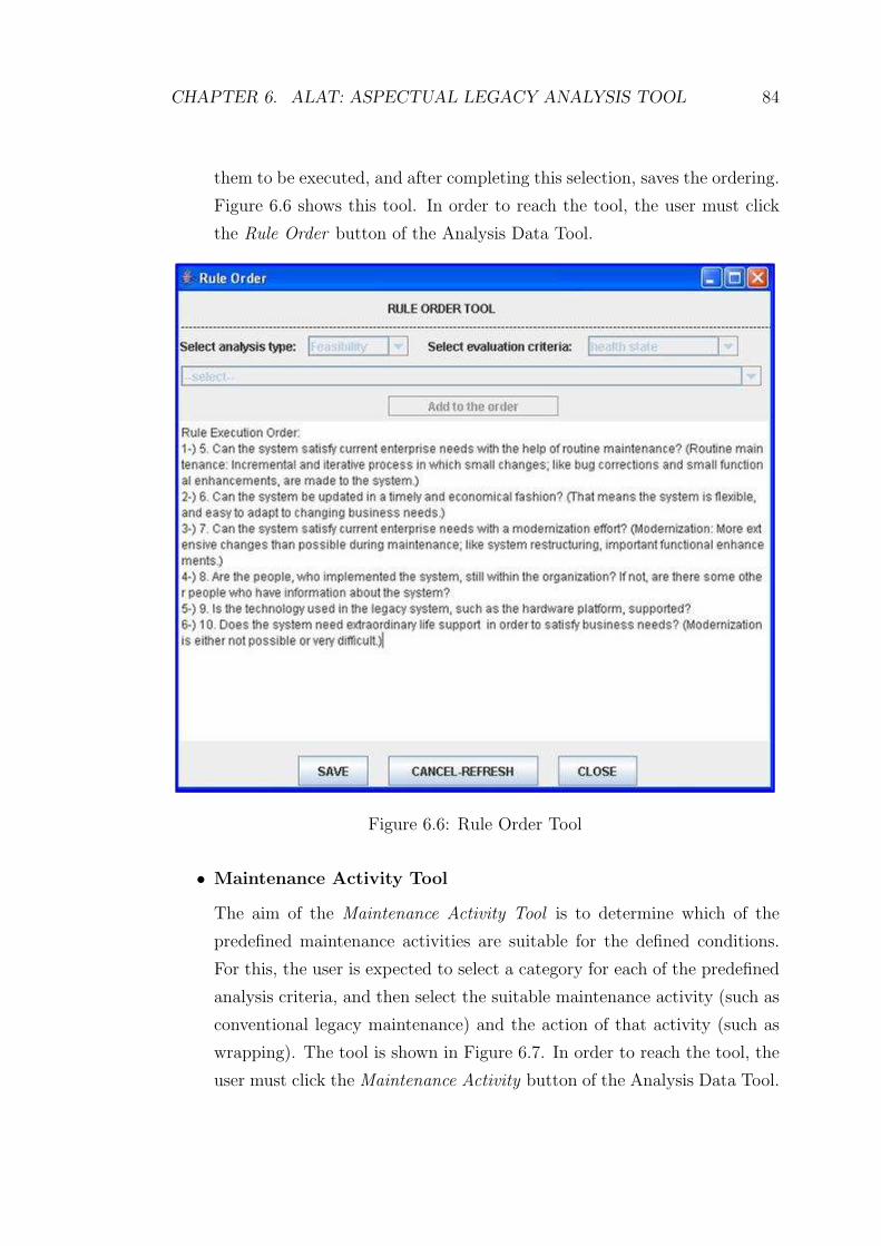
CHAPTER 6. ALAT: ASPECTUAL LEGACY ANALYSIS TOOL 84
them to be executed, and after completing this selection, saves the ordering.
Figure 6.6 shows this tool. In order to reach the tool, the user must click
the Rule Order button of the Analysis Data Tool.
Figure 6.6: Rule Order Tool
• Maintenance Activity Tool
The aim of the Maintenance Activity Tool is to determine which of the
predefined maintenance activities are suitable for the defined conditions.
For this, the user is expected to select a category for each of the predefined
analysis criteria, and then select the suitable maintenance activity (such as
conventional legacy maintenance) and the action of that activity (such as
wrapping). The tool is shown in Figure 6.7. In order to reach the tool, the
user must click the Maintenance Activity button of the Analysis Data Tool.
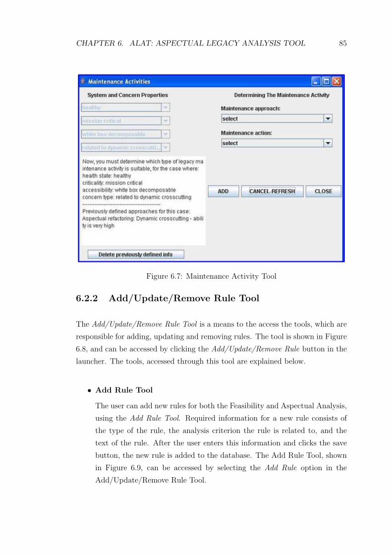
CHAPTER 6. ALAT: ASPECTUAL LEGACY ANALYSIS TOOL 85
Figure 6.7: Maintenance Activity Tool
6.2.2 Add/Update/Remove Rule Tool
The Add/Update/Remove Rule Tool is a means to the access the tools, which are
responsible for adding, updating and removing rules. The tool is shown in Figure
6.8, and can be accessed by clicking the Add/Update/Remove Rule button in the
launcher. The tools, accessed through this tool are explained below.
• Add Rule Tool
The user can add new rules for both the Feasibility and Aspectual Analysis,
using the Add Rule Tool. Required information for a new rule consists of
the type of the rule, the analysis criterion the rule is related to, and the
text of the rule. After the user enters this information and clicks the save
button, the new rule is added to the database. The Add Rule Tool, shown
in Figure 6.9, can be accessed by selecting the Add Rule option in the
Add/Update/Remove Rule Tool.

CHAPTER 6. ALAT: ASPECTUAL LEGACY ANALYSIS TOOL 86
Figure 6.8: Add/Update/Remove Rule Tool
Figure 6.9: Add Rule Tool
• Update Rule Tool
The user has the ability to update the information of the previously defined
rules, using the Update Rule Tool. For this, the user selects a rule from the
list of all rules, and then the information of that rule is shown. If the user
clicks the update button, he/she is allowed to modify the information, and
when he/she clicks the save button, the rule information is updated in the
database. The Update Rule Tool, shown in Figure 6.10, can be accessed by
selecting the Update Rule option in the Add/Update/Remove Rule Tool.
• Remove Rule Tool
The Remove Rule Tool gives the user the ability to remove a predefined
rule. In the tool, the information is shown for the rule selected from the
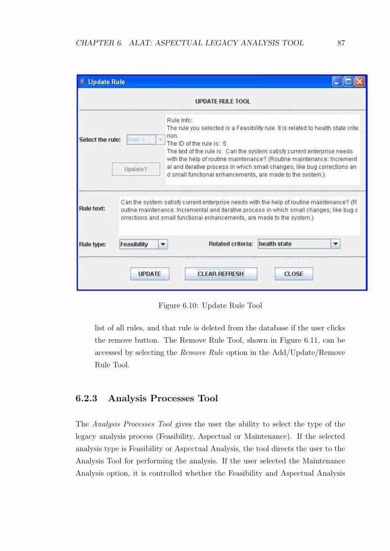
CHAPTER 6. ALAT: ASPECTUAL LEGACY ANALYSIS TOOL 87
Figure 6.10: Update Rule Tool
list of all rules, and that rule is deleted from the database if the user clicks
the remove button. The Remove Rule Tool, shown in Figure 6.11, can be
accessed by selecting the Remove Rule option in the Add/Update/Remove
Rule Tool.
6.2.3 Analysis Processes Tool
The Analysis Processes Tool gives the user the ability to select the type of the
legacy analysis process (Feasibility, Aspectual or Maintenance). If the selected
analysis type is Feasibility or Aspectual Analysis, the tool directs the user to the
Analysis Tool for performing the analysis. If the user selected the Maintenance
Analysis option, it is controlled whether the Feasibility and Aspectual Analysis
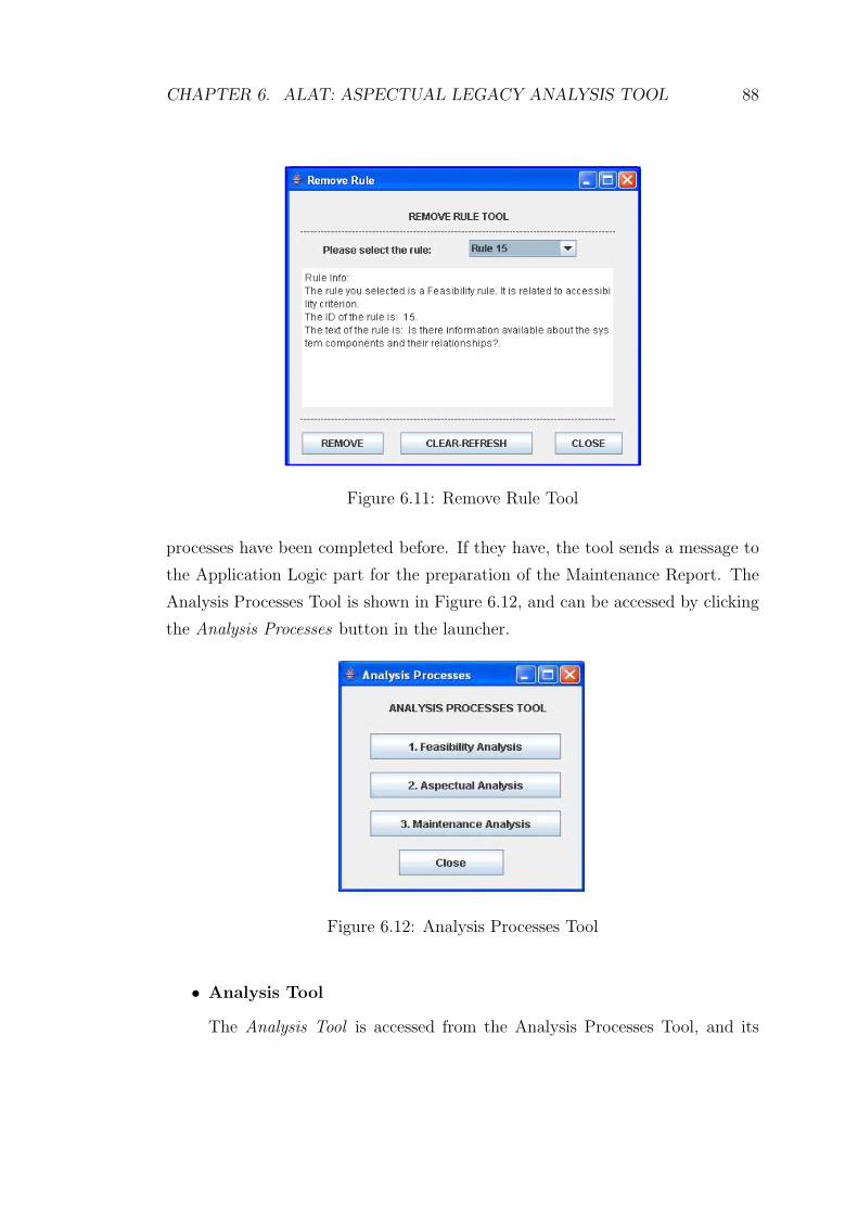
CHAPTER 6. ALAT: ASPECTUAL LEGACY ANALYSIS TOOL 88
Figure 6.11: Remove Rule Tool
processes have been completed before. If they have, the tool sends a message to
the Application Logic part for the preparation of the Maintenance Report. The
Analysis Processes Tool is shown in Figure 6.12, and can be accessed by clicking
the Analysis Processes button in the launcher.
Figure 6.12: Analysis Processes Tool
• Analysis Tool
The Analysis Tool is accessed from the Analysis Processes Tool, and its

CHAPTER 6. ALAT: ASPECTUAL LEGACY ANALYSIS TOOL 89
aim is to perform the analysis of the type selected at that tool. Remem-
ber the rule representation form: IF <condition> THEN <select category> for
Feasibility Analysis, and IF <condition> THEN <select type of concern> for As-
pectual Analysis. The condition part of the rules related to the selected
analysis type are shown to the user one by one, and the user is expected to
provide the answers for these as: yes (meaning the condition is satisfied),
no (meaning the condition is not satisfied), and don’t know (meaning it
isn’t known whether the condition is satisfied or not). When this process is
completed, the tool sends a message to the Application Logic part for the
preparation of the corresponding report. Figures 6.13 and 6.14 show the
Analysis Tool, for which the analysis types are Feasibility and Aspectual
Analysis, respectively.
Figure 6.13: Analysis Tool (Feasibility Analysis performed)
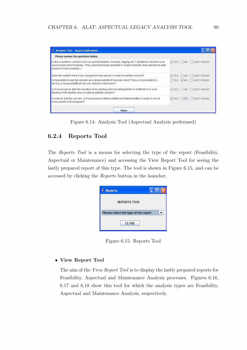
CHAPTER 6. ALAT: ASPECTUAL LEGACY ANALYSIS TOOL 90
Figure 6.14: Analysis Tool (Aspectual Analysis performed)
6.2.4 Reports Tool
The Reports Tool is a means for selecting the type of the report (Feasibility,
Aspectual or Maintenance) and accessing the View Report Tool for seeing the
lastly prepared report of this type. The tool is shown in Figure 6.15, and can be
accessed by clicking the Reports button in the launcher.
Figure 6.15: Reports Tool
• View Report Tool
The aim of the View Report Tool is to display the lastly prepared reports for
Feasibility, Aspectual and Maintenance Analysis processes. Figures 6.16,
6.17 and 6.18 show this tool for which the analysis types are Feasibility,
Aspectual and Maintenance Analysis, respectively.
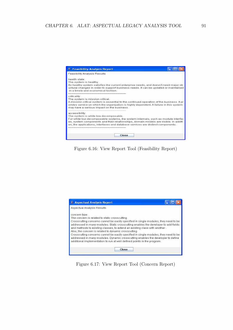
CHAPTER 6. ALAT: ASPECTUAL LEGACY ANALYSIS TOOL 91
Figure 6.16: View Report Tool (Feasibility Report)
Figure 6.17: View Report Tool (Concern Report)

CHAPTER 6. ALAT: ASPECTUAL LEGACY ANALYSIS TOOL 92
Figure 6.18: View Report Tool (Maintenance Report)

CHAPTER 6. ALAT: ASPECTUAL LEGACY ANALYSIS TOOL 93
6.3 Application Logic Part
The most important classes of the Application Logic part are the Analysis and
MaintenanceAnalysis classes. The class Analysis is responsible for: (1) arranging
the rule execution during the analysis operations, (2) evaluating the answers
given by the user during the analysis operations, in order to reach the analysis
results, and (3) preparing the analysis reports. The class MaintenanceAnalysis is
responsible for the coordination of the relations of the Interface part, Application
Logic, and the Database part. The class diagram of the ALAT is shown in Figure
6.19.
Figure 6.19: Class diagram of the ALAT

CHAPTER 6. ALAT: ASPECTUAL LEGACY ANALYSIS TOOL 94
6.4 Database Part
In the system, the JDBC technology is used in order to interact with the database.
The data are stored in tables named Rules, Criteria and Approach. The designs of
these tables are shown in Table 6.1, Table 6.2 and Table 6.3, respectively. Primary
keys of the tables are as follows: RuleID field for the Rules Table, AnalysisType-
CriterionName-CategoryName fields for the Criteria Table, and No field for the
Approach Table.
Field Name Data Type Description
RuleID Number Identifier of the ruleIndicates the analysis type to which
AnalysisType Text the rule belongs
Indicates the name of the analysisCriterion Text criterion that the rule is related to
Indicates the rule text that is shownRuleText Text to the user during the analysis processes
Indicates in which order the rule isexecuted during the analysis process
ExecutionOrder Number (the rules of a criterion are ordered in between)
Table 6.1: Rules table

CHAPTER 6. ALAT: ASPECTUAL LEGACY ANALYSIS TOOL 95
Field Name Data Type Description
Indicates the analysis type to whichAnalysisType Text the criterion belongs
CriterionName Text Indicates the name of the criterionIndicates name of the category
CategoryName Text of the criterion
Explains the meaning ofExplanation Text belonging to the category
Indicates the conditions for belonging to thecategory. The conditions consist of the IDsof the related rules and the answers that
Requirements Text must be given for these rules
Indicates if more than one categoryMoreThanOneValid Yes/No of the criterion can be valid at the same time
Table 6.2: Criteria table
Field Name Data Type Description
No Number The identifier of the maintenance activityIndicates the name of the maintenance
MaintenanceApproach Text approach
Indicates the name of one of theActivity Text techniques of the maintenance approach
Indicates the information aboutwhen this technique is suitable. Thisinformation consists of the name of thecriterion and its corresponding category,
Properties Text for all types of analysis criteria
Indicates the ability of performing themaintenance activity, for the case with the
Ability Text properties specified in the Properties field
Table 6.3: Approach table

CHAPTER 6. ALAT: ASPECTUAL LEGACY ANALYSIS TOOL 96
6.5 Summary
In this chapter we presented the ALAT, which implements the rules of the ALAP.
We explained the three main parts of the tool, Interface, Application Logic and
Database parts, in detail. The legacy maintainer can utilize the tool in order to
analyze a legacy system that he/she wants to enhance with a set of concerns, and
decide which maintenance approach to use.
Chapter 7
Aspectual Refactoring
In Chapter 5, we have defined a process that analyzes a legacy system that needs
to be enhanced and the concern, and produces a Maintenance report which pro-
vides the maintenance approach suitable for enhancing the legacy system with
the concern. In the process, the maintenance approach, suggested in the Main-
tenance report, for enhancing a maintainable system with a crosscutting concern
was aspectual refactoring. In this chapter, in Section 7.1 we explain what as-
pectual refactoring is, and in Section 7.2 we explain several aspectual refactoring
techniques, and give examples for some techniques.
7.1 Definition
Aspectual refactoring is a technique, which combines AOP and refactoring in
order to refactor an object-oriented legacy system in an aspect-oriented way; and
makes it possible to reorganize code containing crosscutting concerns to get rid
of code tangling and code scattering.
In order to understand aspectual refactoring, we must first clarify what refac-
toring means. Refactoring [16] is a technique to restructure object-oriented code
in a disciplined way. In refactoring, the software system is changed in such a way
97

CHAPTER 7. ASPECTUAL REFACTORING 98
that the external behavior of the code is not changed but its internal structure is
improved, and the code becomes easier to understand and maintain.
We will use the Logging Scenario, which is explained in Section 3.2, as an
example implementation of refactoring. In order to add the logging concern, we
write a class Logger, with a log method; and call this method from the related
methods of classes Drugstore, Patient and Doctor. Figure 7.1 shows the code of
these classes after the addition of logging concern.
public class Drugstore {
...
public String makeSale(String pName,ArrayList drugs,int payment,
Date sDate) {
...
Logger.log ("Store",this.name,"Sale Information: "+ "Date: "+ sDate.toString()+
" Patient name: "+pName+
" Total payment: "+ payment);
}
}
public class Patient {
...
public void addPrescription(Prescription pres){
...
Logger.log ("Patient",this.name,"Prescription Information: "+ "Date: "+pres.getDate().toString()+
" Doctor name: "+ pres.getDoctorName());
}
}
public class Doctor {
...
public String givePrescription(String pname, ArrayList presDrugs,
Date date){
...
Logger.log ("Doctor",this.name,"Prescription Information: "+ "Date: "+date.toString()+" Patient name: "+pname);
}
}
Figure 7.1: Doctor, Drugstore and Patient classes before any refactoring
One of the refactoring techniques explained in [16] is Extract method refactor-
ing, which involves turning a code fragment into a method whose name explains
its purpose. Figure 7.2 shows the code of the classes after applying extract method
refactoring. Although the logic of logging is encapsulated in a separate method,
by this refactoring; the code-tangling problem, explained in Section 3.3, still re-
mains because of the call to the log method of class Logger, in multiple places. As
can be seen from the example, refactoring is not sufficient for dealing with cross-
cutting concerns, since it is a technique for restructuring code; not a technology
for modularizing crosscutting concerns. In order to modularize the crosscutting

CHAPTER 7. ASPECTUAL REFACTORING 99
concerns in legacy systems, aspectual refactoring techniques must be applied.
public class Drugstore {
...
public String makeSale(String pName,ArrayList drugs,int payment,Date
sDate){
...
log ("Store",this.name,"Sale Information: "+"Date: "+
sDate.toString()+" Patient name: "+pName+" Total payment: "+
payment);
}
public void log(String logType,String typeName,String fileInfo){
Logger.log(logType,typeName,fileInfo);
}
}
public class Patient {
...
public void addPrescription(Prescription pres){
...
log ("Patient",this.name,"Prescription Information: "+"Date: "+
pres.getDate().toString()+" Doctor name: "+
pres.getDoctorName());
}
public void log(String logType,String typeName,String fileInfo){
Logger.log(logType,typeName,fileInfo);
}
}
public class Doctor {
...
public String givePrescription(String pname, ArrayList
presDrugs,Date date){
...
log ("Doctor",this.name,"Prescription Information: "+"Date: "+
date.toString()+" Patient name: "+pname);
}
public void log(String logType,String typeName,String fileInfo){
Logger.log(logType,typeName,fileInfo);
}
}
Figure 7.2: Doctor, Drugstore and Patient classes after conventional refactoring
7.2 Aspectual Refactoring Techniques
Aspectual refactoring can be applied to improve the understandability and the
structure of either non-aspect code, as explained in [17], [23] and [27], or existing
aspect-oriented code, as explained in [18]. In this study we are interested in the
first one, and in particular, refactoring of object-oriented legacy code. Several
aspectual refactoring patterns have been identified. These are briefly explained
below.

CHAPTER 7. ASPECTUAL REFACTORING 100
7.2.1 Extract method calls
When different parts of a program include similar behavior and so that the pro-
gram has a duplicated piece of code in multiple places; the extract method refac-
toring can be used to encapsulate the duplicated logic in a new method, and
replace each original piece of code with a call to the new method. But then there
will be calls to the new method in multiple places of the program. Extract method
calls refactoring [23] can be used to encapsulate those calls in an aspect, which
contains a pointcut capturing all the points where the method must be called and
advises this pointcut with the call to the refactored method. Figure 7.3, taken
from [23], shows the application of extract method calls refactoring.
Figure 7.3: Extract method calls refactoring [23]
Consider the Logging scenario explained in Section 3.2. Logging concern
must be added to a legacy system. We have applied the ALAP, the process
we explained in Chapter 5, for finding the best approach for adding the logging
concern to the system. The process has produced a Maintenance report as the
result. Suppose the results of the Maintenance report are as follows: The legacy
system is mission critical, healthy and white box decomposable, and the concern
logging is a crosscutting concern, which is related to dynamic crosscutting. Also
the ability of the legacy system for implementing dynamic crosscutting is very
high. Finally, the suggested maintenance approach is aspectual refactoring. Here,
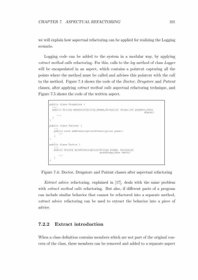
CHAPTER 7. ASPECTUAL REFACTORING 101
we will explain how aspectual refactoring can be applied for realizing the Logging
scenario.
Logging code can be added to the system in a modular way, by applying
extract method calls refactoring. For this, calls to the log method of class Logger
will be encapsulated in an aspect, which contains a pointcut capturing all the
points where the method must be called and advises this pointcut with the call
to the method. Figure 7.4 shows the code of the Doctor, Drugstore and Patient
classes, after applying extract method calls aspectual refactoring technique, and
Figure 7.5 shows the code of the written aspect.
public class Drugstore {
...
public String makeSale(String pName,ArrayList drugs,int payment,Date
sDate){
...
}
}
public class Patient {
...
public void addPrescription(Prescription pres){ ...
}
}
public class Doctor {
...
public String givePrescription(String pname, ArrayList
presDrugs,Date date){
...
}
}
Figure 7.4: Doctor, Drugstore and Patient classes after aspectual refactoring
Extract advice refactoring, explained in [17], deals with the same problem
with extract method calls refactoring. But also, if different parts of a program
can include similar behavior that cannot be refactored into a separate method,
extract advice refactoring can be used to extract the behavior into a piece of
advice.
7.2.2 Extract introduction
When a class definition contains members which are not part of the original con-
cern of the class, these members can be removed and added to a separate aspect

CHAPTER 7. ASPECTUAL REFACTORING 102
public aspect LoggerAspect {
//logging the operation of drugstore pointcut DrugstoreLog(Drugstore ds,String pname,ArrayList drugs,
int payment,Date sdate): execution(String Drugstore.makeSale (String,ArrayList,int,Date))
&& target(ds) && args(pname,drugs,payment,sdate);
after(Drugstore ds,String pname,ArrayList drugs,int payment,
Date sdate): DrugstoreLog(ds,pname,drugs,payment,sdate){ log("Store",ds.getName(),"Sale Information: "+ "Date: "+ sdate.toString()+" Patient name: "+pname+
" Total payment: "+ payment); }
//logging the operation of doctor
pointcut DoctorLog(Doctor d,String pname,ArrayList presDrugs, Date date): execution(String Doctor.givePrescription(String,ArrayList,Date))
&& target(d) && args(pname,presDrugs,date);
after(Doctor d,String pname,ArrayList presDrugs,Date date):
DoctorLog(d,pname,presDrugs,date){ log("Doctor",d.getName(),"Prescription Information: "+
"Date: "+ date.toString()+" Patient name: "+pname); }
//logging the operation of patient pointcut PatientLog(Patient p,Prescription pres): execution(void Patient.addPrescription(Prescription))
&& target(p) && args(pres);
after(Patient p,Prescription pres): PatientLog(p,pres){ log("Patient",p.getName(),"Prescription Information: "+ "Date: "+ pres.getDate().toString()+
" Doctor name: "+pres.getDoctorName()); }
public void log(String logType,String typeName,String fileInfo){ Logger.log(logType,typeName,fileInfo); }
}
Figure 7.5: LoggerAspect.java
by extract introduction refactoring [17]. This technique corresponds to the two
techniques explained in [27]: move field from class to inter-type declaration tech-
nique for fields, and move method from class to inter-type declaration technique
for methods.
7.2.3 Extract interface implementation
When more than one class implements an interface, this may result in duplicated
code required to implement this interface. This problem can be solved by extract
interface implementation [23] refactoring, by writing an aspect that introduces

CHAPTER 7. ASPECTUAL REFACTORING 103
the default implementation to the interface.
7.2.4 Extract exception handling
Exception handling is a crosscutting concern; and in many cases, the exception
handling code, which consists of try/catch blocks, is duplicated in many places.
The aspectual refactoring technique extract exception handling may be used to
extract the duplicated code into a separate aspect [23].
We will give an example for the implementation of this technique from the DIS
code. Consider the Exception Handling scenario explained in Section 3.2. The
scenario requires to update the way of exception handling in DIS code. Figures
7.6 and 7.7 show the code of the classes MainSystem, FrmDoc, FrmDS, FrmPres.
There are duplicated try/catch blocks in all three frames, and duplicated throw
logic in many methods of class MainSystem.
In order to be able to simply update the exception handling concern, we must
modularize the exception handling code. For this, we write an aspect and extract
exception handling code to this aspect. Then realizing the scenario gets easier,
and the only thing to do is to change the aspect code. Figures 7.8 and 7.9 show
the code of FrmDoc, FrmDS, FrmPres and MainSystem classes after applying
extract exception handling aspectual refactoring. Figure 7.10 shows the code of
the written aspect.
7.2.5 Replace override with advice
When there is a need to add additional common behavior to many methods of a
class, this can be done by replace override with advice refactoring [23], by creating
a subclass of the class that is dealt with, and writing an aspect which advises the
methods of the subclass with the additional behavior.

CHAPTER 7. ASPECTUAL REFACTORING 104
public class MainSystem {
...
public ArrayList getDrugNames() throws Exception { ArrayList names=new ArrayList();
for (int i=0;i<this.drugs.size();i++){
names.add(((Drug)drugs.get(i)).getName());
}
if (names.size()==0) throw new Exception("No drugs have been added to the system."); return names;
}
public ArrayList getPatientNames() throws Exception {
ArrayList names=new ArrayList();
for (int i=0;i<this.patients.size();i++){
names.add(((Patient)patients.get(i)).getName());
} if (names.size()==0) throw new Exception("No patients have been
registered to the system."); return names;
}
public ArrayList getPatientNamesOfDoc(String doc) throws Exception {
ArrayList arr=findDoctor(doc).getPatientNames();
if (arr.size()==0){ String s="No patients are registered to the doctor! In
order to give prescription to a patient, he/she must be registered to the doctor."); throw new Exception(s);
} return arr;
}
...
}
Figure 7.6: Class MainSystem before applying any aspectual refactoring

CHAPTER 7. ASPECTUAL REFACTORING 105
public class FrmDoc extends JFrame {
...
public boolean loadComboPatient() throws Exception{
jComboBox1.removeAllItems();
try{
ArrayList names=FrmMain.coordinator.getPatientNames();
for (int i=0;i<names.size();i++){
jComboBox1.addItem((String)names.get(i));
}
return true;
this.show();
}catch(Exception ex){
giveError(ex.toString());
return false;
}
}
...
}
public class FrmDS extends JFrame {
...
public boolean loadComboDrug(){
jComboBox1.removeAllItems();
try{
ArrayList names=FrmMain.coordinator.getDrugNames();
for (int i=0;i<names.size();i++){
jComboBox1.addItem((String)names().get(i));
}
return true;
}catch(Exception ex){
giveError(ex.toString());
return false;
} }
public boolean loadComboPatient(){
jComboBox5.removeAllItems();
try{
ArrayList names=FrmMain.coordinator.getPatientNames();
for (int i=0;i<names.size();i++){
jComboBox5.addItem((String)FrmMain.names.get(i));
}
return true;
}catch(Exception ex){
giveError(ex.toString());
return false;
}
}
}
public class FrmPres extends JFrame {
...
public void loadComboPatient(){
try{
ArrayList names=FrmMain.coordinator.getPatientNamesOfDoc(docName);
int c=jComboBox2.getItemCount()-1;
for (int i=c;i<pnames.size();i++){
jComboBox2.addItem((String)pnames.get(i));
}
}catch(Exception ex) {
giveError(ex.toString());
this.dispose();
this.setVisible(false);
}
}
}
Figure 7.7: FrmDoc, FrmDS and FrmPres classes before applying any aspectualrefactoring

CHAPTER 7. ASPECTUAL REFACTORING 106
public class FrmDoc extends JFrame { //no exception handling code ...
public boolean loadComboPatient() throws Exception{
jComboBox1.removeAllItems();
ArrayList names=FrmMain.coordinator.getPatientNames();
for (int i=0;i<names.size();i++){
jComboBox1.addItem((String)names.get(i));
}
return true;
this.show();
}
...
}
public class FrmDS extends JFrame { //no exception handling code
...
public boolean loadComboDrug(){
jComboBox1.removeAllItems();
ArrayList names=FrmMain.coordinator.getDrugNames();
for (int i=0;i<names.size();i++){
jComboBox1.addItem((String)names().get(i));
} return true;
}
public boolean loadComboPatient(){
jComboBox5.removeAllItems();
ArrayList names=FrmMain.coordinator.getPatientNames();
for (int i=0;i<names.size();i++){
jComboBox5.addItem((String)FrmMain.names.get(i));
}
return true;
}
}
public class FrmPres extends JFrame { //no exception handling code ...
public void loadComboPatient(){
ArrayList names=FrmMain.coordinator.getPatientNamesOfDoc(docName);
int c=jComboBox2.getItemCount()-1;
for (int i=c;i<pnames.size();i++){
jComboBox2.addItem((String)pnames.get(i));
}
}
}
Figure 7.8: FrmDoc, FrmDS and FrmPres classes after applying extract exceptionhandling aspectual refactoring

CHAPTER 7. ASPECTUAL REFACTORING 107
public class MainSystem{ //no exception handling code
…
public ArrayList getDrugNames(){
ArrayList names=new ArrayList();
for (int i=0;i<this.drugs.size();i++){
names.add(((Drug)drugs.get(i)).getName());
}
return names;
}
public ArrayList getPatientNames(){
ArrayList names=new ArrayList();
for (int i=0;i<this.patients.size();i++){
names.add(((Patient)patients.get(i)).getName());
}
return names;
}
public ArrayList getPatientNamesOfDoc(String doc){
return findDoctor(doc).getPatientNames();
}
…
}
Figure 7.9: Class MainSystem after applying extract exception handling aspectualrefactoring
public aspect ExceptionHandlerAspect {
after(MainSystem ms) returning(ArrayList arr) throws Exception:
target(ms) && execution (ArrayList getPatientNames()){ if (arr.size()==0)
throw new Exception("No patients are registered to the system."); }
after(MainSystem ms) returning(ArrayList arr) throws Exception: target(ms) && execution (ArrayList getDrugNames()){
if (arr.size()==0) throw new Exception("No drugs are added to the system.");
}
after(MainSystem ms) returning(ArrayList arr) throws Exception:
target(ms) && execution (ArrayList getPatientNamesOfDoc(String)){ if (arr.size()==0) throw new Exception("No patients are registered to the doctor! In order to give prescription to a patient, he/she must
be registered to the doctor."); }
after (MainSystem ms) throwing(Exception e): ( execution (ArrayList getPatientNames()) ||
execution (ArrayList getDrugNames()) || execution (ArrayList getPatientNamesOfDoc(String)) ) && target(ms){
giveError(e); }
void giveError(Exception e){ MsgDialog msg = new MsgDialog();
msg.jTextArea1.append(e.toString()); msg.show(); }
}
Figure 7.10: ExceptionHandlerAspect.java
Chapter 8
Conclusions
This thesis provides a systematic approach for analyzing legacy systems and pro-
viding direct guidelines for coping with crosscutting concerns in legacy systems.
The results of the research are the following:
Domain analysis of legacy systems
Based on a thorough literature study to legacy systems, we have categorized
the legacy systems according to business criticality, health state and accessibil-
ity criteria. It appears that for each category of the legacy systems, different
legacy maintenance approaches are required. We have discussed the three ba-
sic legacy maintenance approaches wrapping, migration and redevelopment, and
described the relation between these maintenance approaches and the different
legacy system types.
After a thorough domain analysis on legacy systems, we have investigated the
impact of crosscutting concerns on legacy systems. We have adapted an exam-
ple case, Drugstore Information System for this purpose. We have analyzed the
example case with respect to a set of scenarios that could typically be adapted.
The analysis showed that several scenarios could not be easily integrated in the
legacy example because of the crosscutting property. An example concern is log-
ging the patient information, which had to be added to many places of the system.
108
CHAPTER 8. CONCLUSIONS 109
Existing legacy maintenance approaches do not explicitly consider maintenance
of crosscutting concerns, and likewise adding or updating crosscutting concerns
causes a degradation in the structure of the system, increases complexity, and
reduces the quality factors such as maintainability and understandability of the
system.
ALAP: Aspectual Legacy Analysis Process
As a solution to handling the crosscutting concerns in legacy systems problem,
we have defined a systematic process called Aspectual Legacy Analysis Process
(ALAP) for maintaining legacy systems. The process consists of the three basic
sub-processes Feasibility Analysis, Aspectual Analysis and Maintenance Analysis.
The Feasibility Analysis of the overall process consists of two phases. The first
phase describes the rules for the categorization of the legacy system, and the
second phase describes the rules for evaluating the legacy system with respect to
the ability to implement static and dynamic crosscutting. The Aspectual Analysis
sub-process describes the rules for identifying and specifying aspects in legacy
systems, and finally the Maintenance Analysis provides the rules for determining
the convenient maintenance approaches for the legacy system, using the results
of the previous two sub-processes.
From the Feasibility Analysis sub-process of ALAP we could derive the fol-
lowing basic conclusions:
• Visibility and decomposability of legacy systems determine the possibility of
the application of aspectual refactoring.
In dynamic crosscutting, the aim is to define additional implementation,
that is, to create new behavior at some points in the system. These points
are defined as joinpoints, and these joinpoints are collected in pointcuts. If
we do not know the whole structure of the system, identifying the joinpoints
and hence the pointcuts gets hard, therefore we may fail in defining the right
points to add behavior. In that case, we will also have failed in implementing
the required dynamic crosscutting.
In static crosscutting, the aim is to alter the structure of an existing class,

CHAPTER 8. CONCLUSIONS 110
by adding fields or methods to it, or by extending it with another class, etc.
The visibility is even more important here, since in order to be able to alter
something, firstly you should know it. In order for a static crosscutting, the
system must also be decomposable, which means that the components of
the system can be accessed and viewed separately and independently. The
components must be independent from each other, in a way that making
changes to one module does not require making changes to another module.
As a result, neither dynamic nor static crosscutting seems to be possible for
black box systems, for which, it is the case that we do not know anything
about the internal structure of the system, and source code and documen-
tation of the system are not available. The system that is dealt with needs
to be white box and also decomposable, in order to be able to apply static
and dynamic crosscutting successfully.
• The suitability of a legacy system for extending with AOSD heavily depends
on the system’s health state.
We explained in Section 2.2.2, that healthiness determines to which ex-
tent the system can be maintained. That is why the success of AOSD is
dependent on the system’s health state. Healthy systems are mostly suit-
able for extending with AOSD, since implementing crosscutting is easier for
these systems. Healthy systems satisfy the business needs successfully, and
the changes they need are usually small functional enhancements, which
can be easily done by applying AOSD. On the other hand, ill systems need
important functional enhancements or system restructuring. Functional en-
hancements can be done by dynamic crosscutting, and system restructuring
can be done by static crosscutting, but the recovery of the system highly
depends on the aspects that are implemented. Terminally ill systems have
no use to extend with AOSD, because these systems are no longer main-
tainable, and cannot be recovered by applying AOSD.
• Replaceable systems need not be considered for aspectual refactoring.
Replaceable systems no longer meet business needs and they are technically
inefficient. Their operation is not crucial for the continued operation of the
business they reside in. Hence, as explained in Section 2.4.3, the best thing
CHAPTER 8. CONCLUSIONS 111
to do is to redevelop a replaceable system. Looking from the business per-
spective, it is usually more beneficial and easier to redevelop a replaceable
system from scratch, than trying to modernize it using AOSD techniques.
Based on the analysis guidelines, we have derived some useful heuristics to be
applied during legacy maintenance activities. Although these heuristics cannot
always be very strictly applied, they can help the legacy maintainer in deciding
whether AOSD can be applied to enhance the concerns.
ALAT: Aspectual Legacy Analysis Tool
ALAP has been implemented in the Aspectual Legacy Analysis Tool (ALAT).
In ALAT, the user is given the ability to add, update and remove the rules. In
addition, he/she can change the information related to the analysis criteria used
in the Feasibility Analysis sub-process. The tool we have implemented consists
of three main parts: User Interface part, which consists of a set of tools for
implementing the legacy analysis process; Application Logic part, which defines
the application logic and contains the classes applied by the tools of the User
Interface part, and finally the Database part, which persistently stores the data
that is operated on in the rules.
The future work to this research could be basically deriving rules for selecting
appropriate aspectual refactoring techniques, for different types of legacy systems
and concerns.

Bibliography
[1] Hyperspace web site (http://www.research.ibm.com/hyperspace).
[2] Free on-line dictionary of computing (http://wombat.doc.ic.ac.uk/), 1996.
[3] Xerox corporation. the aspectj programming guide
(http://www.aspectj.org/), 2002.
[4] M. Aksit, J. Bosch, W. Sterren, and L. Bergmans. Real-time specification
inheritance anomalies and real-time filters. Lecture Notes in Computer Sci-
ence, pages 386–407, 1994.
[5] M. Aksit, K. Wakita, J. Bosch, L. Bergmans, and A. Yonezawa. Abstracting
object interactions using composition filters. In Proceedings of the Workshop
on Object-Based Distributed Programming, pages 152–184. Springer-Verlag,
1994.
[6] K. Bennet. Legacy systems: Coping with success. IEEE Software, pages
19–23, 1995.
[7] L. Bergmans, M. Aksit, and B. Tekinerdogan. Aspect composition using
composition filters. In Software Architectures and Component Technology:
The State of the Art in Research and Practice.
[8] L. Bergmans, M. Aksit, K. Wakita, and A. Yonezawa. An object-oriented
model for extensible concurrent systems: The composition filters approach,
1995.
[9] J. Bisbal, D. Lawless, B. Wu, and J. Grimson. Legacy information systems:
Issues and directions. IEEE Software, 16(5):103–111, 1999.
112
BIBLIOGRAPHY 113
[10] J. Bisbal, D. Lawless, B. Wu, and J. Grimson. Legacy information sys-
tems migration: A brief review of problems, solutions, and research issues.
Technical Report TCD-CS-1999-38, Computer Science Department, Trinity
College Dublin, 1999.
[11] M. L. Brodie and M. Stonebraker. DARWIN: On the incremental migration
of legacy information systems. DOM Technical Report TR-0222-10-92-165,
GTE Laboratories Inc., Waltham, Massachusetts 02254, 1993.
[12] M. L. Brodie and M. Stonebraker. Migrating legacy systems: Gateways,
interfaces, and the incremental approach, 1995.
[13] S. Comella-Dorda. Black box modernization of information systems. Techni-
cal report, Carnegie Mellon University Software Engineering Institute, 2001.
[14] S. Comella-Dorda, K. Wallnau, R. C. Seacord, and J. Robert. Survey of
legacy system modernization approaches. Technical Report CMU/SEI-00-
TR-003, Carnegie Mellon University, Software Engineering Institute, 2000.
[15] A. Dardenne. On the use of scenarios in requirements acquisition. CIS-
TR-93-17, Department of Computer and Information Science, University of
Oregon, 1993.
[16] M. Fowler, K. Beck, J. Brant, W. Opdyke, and D. Roberts. Refactoring:
Improving the Design of Existing Code. Addison-Wesley, 1st edition, 1999.
[17] S. Hanenberg and R. U. Christian Oberschulte. Refactoring of aspect-
oriented software. In Proceedings of the NetObject Days, 2003.
[18] M. Iwamoto and J. Zhao. Refactoring aspect-oriented programs. In The 4th
AOSD Modeling With UML Workshop, 2003.
[19] R. Kazman, G. Abowd, L. Bass, and P. Clements. Scenario-based analysis
of software architectures. IEEE Software, pages 47–55, 1996.
[20] G. Kiczales, E. Hilsdale, J. Hugunin, M. Kersen, J. Palm, and W. G. Gris-
wold. An overview of AspectJ. In Proceedings of the European Conference
on Object-Oriented Programming, volume 2072 of Lecture Notes in Computer
BIBLIOGRAPHY 114
Science, pages 327–353, Berlin, Heidelberg, and New York, 2001. Springer-
Verlag.
[21] G. Kiczales, J. Lamping, A. Menhdhekar, C. Maeda, C. Lopes, J.-M. Lo-
ingtier, and J. Irwin. Aspect-oriented programming. In M. Aksit and S. Mat-
suoka, editors, Proceedings of the European Conference on Object-Oriented
Programming, volume 1241, pages 220–242. Springer-Verlag, Berlin, Heidel-
berg, and New York, 1997.
[22] R. Laddad. I want my AOP. Javaworld, 2002.
[23] R. Laddad. Aspect-oriented refactoring series. TSS, 2003.
[24] K. Lieberherr, D. Orleans, and J. Ovlinger. Aspect-oriented programming
with adaptive methods. Communications of the ACM, 44(10):39–41, 2001.
[25] K. J. Lieberherr, I. Holland, and A. J. Riel. Object-oriented programming:
An objective sense of style. In OOPSLA Conference, Special Issue of SIG-
PLAN Notices, pages 323–334, San Diego, CA, 1998.
[26] K. J. Lieberherr and I. M. Holland. Assuring good style for object-oriented
programs. IEEE Software, 6(5):38–48, 1989.
[27] M. P. Monteiro and J. M. Fernandes. Object-to-aspect refactorings for
feature extraction. In Proceedings of the 3rd International Conference on
Aspect-Oriented Software Development (AOSD 2004), Lancaster, United
Kingdom, 2004.
[28] J. Q. Ning, A. Engberts, and W. Kozaczynski. Automated support for legacy
code understanding. Communications of the ACM, 37(5):50–57, 1994.
[29] D. Orleans and K. Lieberherr. Dj: Dynamic adaptive programming in Java.
In Reflection 2001: Meta-level Architectures and Separation of Crosscutting
Concerns, Kyoto, Japan, 2001.
[30] H. Ossher and P. Tarr. Multi-dimensional separation of concerns using hy-
perspaces. Research Report 21452, IBM, 1999.

BIBLIOGRAPHY 115
[31] H. Ossher and P. Tarr. Multi-dimensional separation of concerns and the
hyperspace approach. In Proceedings of the Symposium on Software Ar-
chitectures and Component Technology: The State of the Art in Software
Development, Kluwer, 2000.
[32] R. Richardson, D. Lawless, J. Bisbal, B. Wu, J. Grimson, and V. Wade. A
survey of research into legacy system migration. Technical Report TCD-CS-
1997-01, Computer Science Department, Trinity College, Dublin, 1997.
[33] A. Simon. Systems Migration - A Complete Reference. New York : Van
Nostrand Reinhold, 1st edition, 1992.
[34] P. Stevens and R. Pooley. Systems reengineering patterns. In Proceedings of
the ACM-SIGSOFT Foundations of Software Engineering, 1998.
[35] P. Tarr, H. Ossher, W. Harrison, and S. Sutton. N degrees of separation:
Multi-dimensional separation of concerns. In Proceedings of the International
Conference on Software Engineering (ICSE’99), 1999.
[36] P. Tarr, H. Ossher, and S. M. Sutton. Hyperj: Multi-
dimensional separation of concerns for java. Presentation Slides
(http://www.netobjectdays.org/pdf/01/slides/tutorial/sutton.pdf).
[37] B. Tekinerdogan and M. Aksit. Solving the modeling problems of object-
oriented languages by composing multiple aspects using composition filters.
1998.
[38] B. Tekinerdogan and M. Aksit. Deriving design aspects from conceptual
models. In: S. Demeyer and J. Bosch (eds.), Object-Oriented Technology,
ECOOP ’98 Workshop Reader, LNCS 1543, Springer-Verlag, pages 410-414,
1999.
[39] S. R. Tilley and D. B. Smith. Perspectives on legacy system reengineer-
ing. Software Engineering Institute, Carnegie Mellon University, Pittsburgh,
1996.
[40] M. Voelter. AOP in Java. Java Report (www.adtmag.com), 2000.

BIBLIOGRAPHY 116
[41] I. Warren. The renaissance of legacy systems. Practitioner Series. Springer
Verlag, 2000.
[42] N. Weiderman, L. Northrop, D. Smith, S. Tilley, and K. Wallnau. Implica-
tions of distributed object technology for reengineering. Technical Report
CMU/SEI-97-TR-005, Carnegie Mellon University, Software Engineering In-
stitute, 1997.
[43] B. Wu, D. Lawless, J. Bisbal, J. Grimson, R. Richardson, V. Wade, and
D. O’Sullivan. The butterfly methodology : A gateway-free approach for
migrating legacy information systems. In Proceedings of the 3rd IEEE Con-
ference on Engineering of Complex Computer Systems (ICECCS ’97), pages
200–205, Villa Olmo, Como, Italy, 1997.
[44] B. Wu, D. Lawless, J. Bisbal, J. Grimson, V. Wade, D. O’Sullivan, and
R. Richardson. Legacy system migration: A legacy data migration engine.
In Proceedings of the 16th International Database Conference, pages 129–138,
Brno, Czech Republic, 1997.