assembly of drive shaft (006). -...
TRANSCRIPT


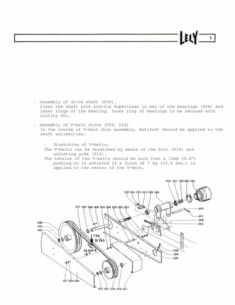
Assembly of drive shaft (006). Clean the shaft with Loctite Superclean in way of the bearings (004) and inner rings of the bearing. Inner ring of bearings to be secured with Loctite 601.
Assembly of V belt discs (009, 018) In the course of V belt disc assembly. Antifret should be applied to the shaft estremities.
Stretching of V belts. The V belts can be stretched by means of the bolt (016) and
adjusting yoke (012). The tension of the V belts should be such that a 15mm (0.6 )
pushing in is achieved if a force of 7 kg (15.4 lbs.) is applied to the center of the V belt.

Bearing (112) to be mounted on shaft (110) with Loctite 601. Take care that surfaces to be glued are properly degreased first.
Adjustment of the gears (106) and (116). Flank clearance and tooth pattern to be adjusted with shims (106) and (118). Flank clearance: 0.12
0.25 mm (0.03
0.06 ).
Bearing (122) to be mounted in bearing cover (124), with the gasket (G) fitted as indicated. Replace the gasket (123) by a new one after dismounting of the bearing cover. Bolts (127) to be mounted on gearbox with fluid gasket.
Dismounting of the shaft (130) from the intermediate gear (132). Mind: The shaft has a left-hand screw thread. After the shaft has been loosened, it can be pulled out of the gearbox by means of a bolt or threaded end (Mb), which can be screwed into the shaft after removal of the plug (128). During assembly, the shaft should be fixed with a torque of 5 kgm/37 ft/lbs.
Attention: Since during disassembly of the shaft, the sealing rings (138) of the lowermost gear may incur damage, these rings should always be replaced.
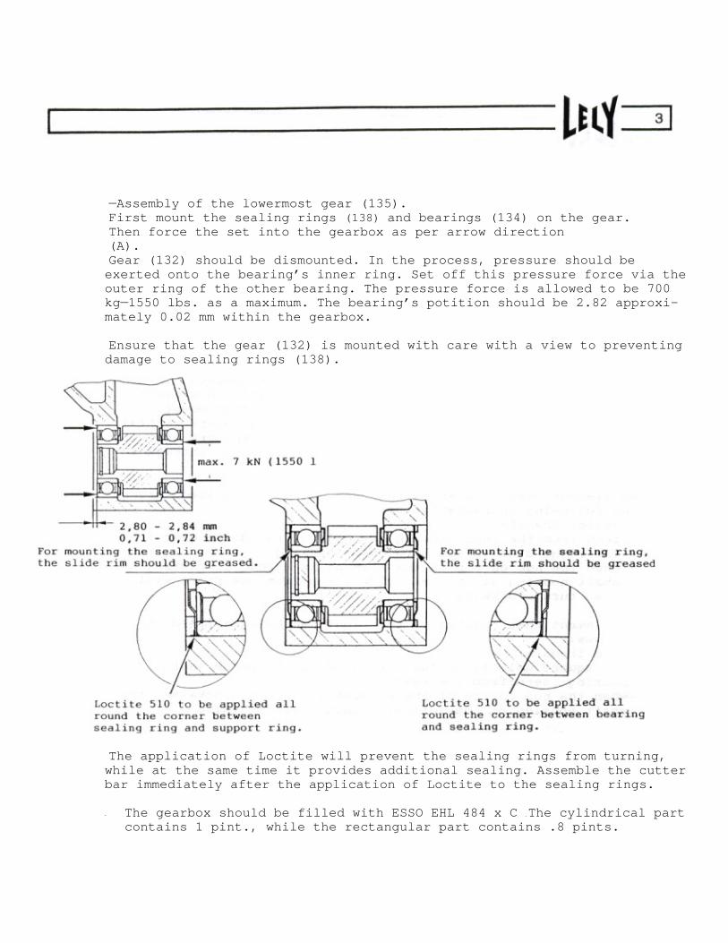
Assembly of the lowermost gear (135). First mount the sealing rings (138) and bearings (134) on the gear. Then force the set into the gearbox as per arrow direction (A). Gear (132) should be dismounted. In the process, pressure should be exerted onto the bearing s inner ring. Set off this pressure force via the outer ring of the other bearing. The pressure force is allowed to be 700 kg 1550 lbs. as a maximum. The bearing s potition should be 2.82 approxi-mately 0.02 mm within the gearbox.
Ensure that the gear (132) is mounted with care with a view to preventing damage to sealing rings (138).
The application of Loctite will prevent the sealing rings from turning, while at the same time it provides additional sealing. Assemble the cutter bar immediately after the application of Loctite to the sealing rings.
- The gearbox should be filled with ESSO EHL 484 x C . The cylindrical part contains 1 pint., while the rectangular part contains .8 pints.

The Lely Mower is built up of 4,5,6,or 7 independent elements, each of which drive a mowing disc. These elements rotate either to the right or to the left. The elements are interspaced by intermediate spacers. A non standard spacer is mounted between the 1st and 2nd element (both rotating to the right) of the 5 and 7 -disc mower. The elements are driven from the gearbox by a square central shaft. (282). The elements and intermediate spacers are linked up by a connecting bar (283), pre strajned through a nut (280).
An element that rotates to the left can be recognized through the following characteristics:
yellow transfer;
seen from the rear, the square hole of the drive gear is on the right side in the born shaft housing;
when the hub on top of the element is turned clockwise, the shaft housing at the left side (seen from the rear) will also turn clockwise.
An element that rotates to the right can be identified as follows: blue transfer the square hole is on the left side in the borne shaft housing (seen from the rear): when the hub on top of the element is turned clockwise, the shaft housing on the left will turn ant-clockwise

Replacement of an element
Place the mower, after thorough cleaning, on a clean floor. Make sure that during dismounting dirt, dust, etc. cannot gain access to the separation surfaces of the components.
Remove the swathboard. Also, remove the securing plate (278).
The M30 nut (280) is subsequently removed. Now the end component (277), the intermediate components, and the elements can be pushed off the connecting bar and the square central shaft, as far as required in order to reach the element to be dismounted.
Now mount the new element and thereafter the intermediate components, all
in reversed order.
During remounting the following points should be attended to:
Before remounting, clean the separation surfaces of the elements and intermediate components. ESSO Rustbam 397 to be applied to all contact surfaces, to the drive shaft and connecting rod. The drive shaft should be assembled into the cutter bar in such a way ,
that the extremity that has a hole in it is arranged in way of the outer mowing element.
Mount the elements rotating to left and right places and in the proper position (see fig. A). Do not forget the centring ring (260 and 284). The knife fixations on the mowing discs should be turned 90 degrees in respect of the adjacent mowing disc. Hence, the mowing disc should be turned into its right position before the element is pushed onto the square shaft.
If the element does not immediately fit on the square shaft, the mowing disc should be turned 180 degrees (a semi rotation) one or a few times, until finally the element will fit onto the shaft, always showing a 90 degree turn in respect of the adjacent mowing discs.
If an element is mounted without the disc, it should be so adjusted that the square plane on the hub is in line with the bar if the discs are lined up as shown in fig. A. Then mount the disc.
The outer element has been fitted with a small plate (275) with retaining ring (276), which secure the square shaft. This plate + retaining ring are not supplied together withthe elements and should be transposed (or ordered separately) in case of replacement of the outer element.
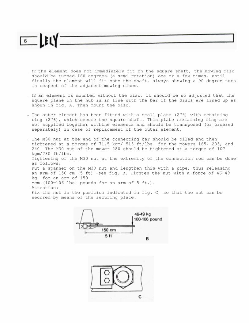
- The M30 nut at the end of the connecting bar should be oiled and then tightened at a torque of 71.5 kgm/ 515 ft/lbs. for the mowers 165, 205, and 240. The M30 nut of the mower 280 should be tightened at a torque of 107 kgm/780 ft/lbs. Tightening of the M30 nut at the extremity of the connection rod can be done as follows: Put a spanner on the M30 nut and lengthen this with a pipe, thus releasing an arm of 150 cm (5 ft)
see fig. B. Tighten the nut with a force of 46 49 kg, for an arm of 150 cm (100 106 lbs. pounds for an arm of 5 ft.).
Attention: Fix the nut in the position indicated in fig. C, so that the nut can be secured by means of the securing plate.

Replacement of Knives
The knives are in LH and RH design. The knives are reversible, so they can be used on both sides. The knife is mounted in the direction of rotation, with the chamber of the cutting side upwards (see figure D). Depending on the disc, the RH or LH knife is mounted. The knives should always be replaced pair and pair, per disc, in order to avoid unbalance in the disc.
Before mounting new knives, check if the knife bolt (257) and stop (259) are not damages or worn off. Always mount new, self securing nuts.
Make sure that the cam of the knife bolt is lodged within the recess of the stop.

Assembly of the slide bearings (329): Bearing outsides to be roughnened with a steel wire brush or sandpaper. Contact surfaces to be cleaned with Loctite Superclean. Loctite 601 to be applied to both surfaces. Assemble bearing with locating rim R (as indicated) and ensure aligning of orifice in bearing with hole for grease nipple.
Molykote BR-2 Plus or Longterm 2 Plus to be applied to sliding surfaces.
Assemble of bearing plate (328). First arrange the cutter bar gearbox in the slide bearing of the chasis beam (311). Then fit the bearing plate on the gearbox. Depending upon the machine s batch specification, the grease nipple is fitted on the front, resp. bottom side. Bolts (331) to be tightened with a torque of 33 ± 2 kgm/240 ± 15 ft/lbs. For the Mower 240 this torque is 35 ± 2 kgm/255 ± 15 ft/lbs., after which securing should be done while using a second nut.

- Adjustment of breakback device (351 360).
Proper adjustment of the breakback device is ensured by pre-straining the spring (357) at
150 mm (5,9 inch) - Mower 165 Mower 205
161 mm (6,3 inch) - Mower 205 (as of S/N 930-2549) Mower 240 Mower 280

Disassembly
Gears
Bearings
Mower
Element
Dismount bearing housing (207). The conical gear (213) can now be taken from the hub (209), after which the hub can be pulled from the bearing housing (207). Two bearings (202) to be removed from the bearing housing. Nilos ring (205) to be removed from hub. Retaining rings (217 and 219) to be taken from housing (201). The pinion and bearings can now be taken from the housing. Shims (206) to be removed.
Assembly
and
Adiustment of Mower
Elements
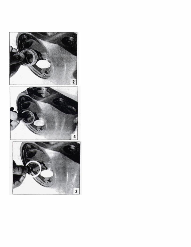
Before proceeding to assembly, all parts should be thoroughly cleaned. Retaining ring (219) to be mounted in the LH and RH orifice in the housing (see photo 1, page 12), according to the required direction of rotation of the mower element. It should be noted that all further photos shown in this instruction set relate to the assembly of an element which rotates to the right.
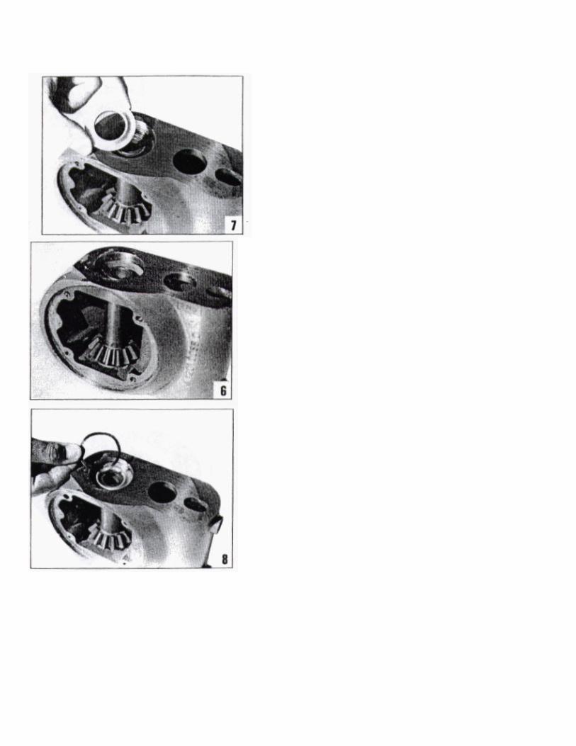
Place two shims (218) with a 0.3 mm thickness on the retaining ring (photo 2). Then the aluminum ring (220) should be placed on the shims (photo 3). Apply an ample quantity of grease (ESSO FIBRAX EP 370) to the Nibs ring (215) and place it on the ring (220) photo 4. Mount the bearing (214) photo 5. Pinion (212) to be mounted photo 6. Bearing (214) to be mounted. Bearing to be pressed to such an extent, that there is no play between the rings, bearings, and pinion. NOTE: If the bearing is put into position by means of a press, the pressure force should amount to 600 700 kg.
Place the Nibs ring (215), after having applied an ample quantity of grease (ESSO EHL 484xC) on it, on the bearing (photo 7). Then fit the spring washer (216) photo 8 and retaining ring (217) - photo 9.
Check the retaining ring (204) for damages and also if it is lodged properly in the groove in the bearing housing (207). Mount one bearing (202), place the support ring (203) photo 10
and fit the second bearing. Apply an ample quantity of grease (ESSO EHL 484 x C) on the Nibs ring (205) and place it in the hub (209).

Mount the hub on the bearing housing (see photo 11). Make sure that the support ring (203) is centered in respect of the bearings (202). Mount the gear (213) in the hub. Secure all parts good and firmly by placing the pressure block (A) on the hub and by tightening with the nut (B) -see photo 12.
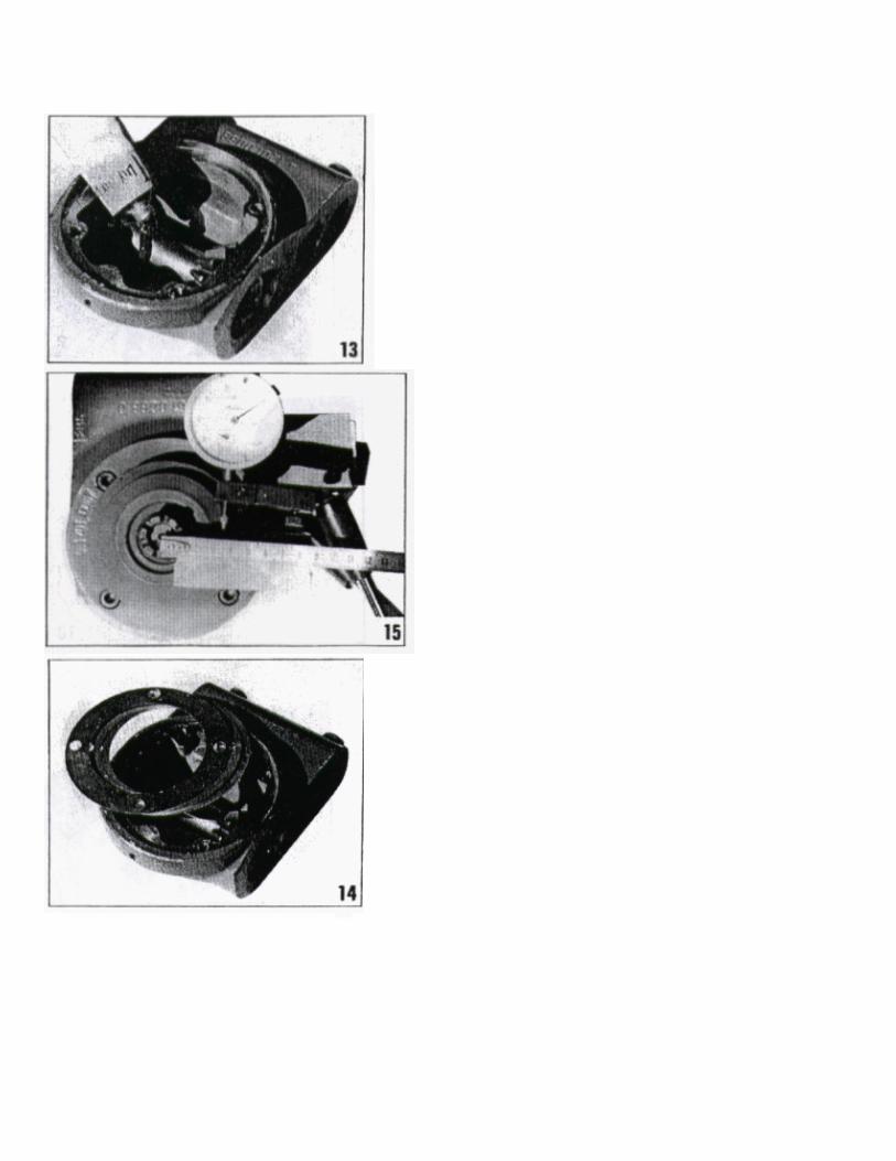
Fill the housing with 3.3 ounces of grease ESSO EHL 484 x C photo 13.
Place shims (206) with a thickness of 0.1
0.25
0.5 mm on the housing (photo 14) and mount the bearing housing. Tighten the cylinder headed screws (208) to a torque of 14.5 ft/lbs.
Turn the hub a few times and measure the flank clearance. This clearance should be between 0.1 and 0.2 mm.
Measuring can be done as follows:
fit a small plate on the gear s threaded end and measure the clearance by means of a micrometer at a distance of 35 mm from the heart of the gear (see photo 15).
Should the clearance be too substantial, resp. too small, then shims (206) should be removed resp. added.