assessment of shear stresses from shrinkage and thermal
TRANSCRIPT

ASSESSMENT OF SHEAR STRESSES FROM SHRINKAGE AND THERMAL DEFORMATION IN WOOD-CONCRETE
BRIDGE BEAMS
K. FURTAK 1,
The aim of the paper is to assess the values of shear (delaminating) stress in the composition plane
between the concrete (RC) deck slab and wood girder from concrete shrinkage, and shrinkage and
swelling of wood, as well as difference in temperature between the wood web and concrete slab.
1. INTRODUCTION
Composite structures have been used for over a hundred years. The classical solution of the steel-
concrete type is composed of the steel girder and concrete (reinforced concrete) slab interacting
with it [4]. Over the years other compositions of materials were used, including the best known
concrete-concrete structures. Sometimes the slab of prestressed concrete was used. The classical
concrete was replaced with fibre concrete [7] or lightweight concrete [10]. Instead of steel,
aluminium [11] and timber girders [1, 4, 6, 8, 9, 12] were applied. Wood-concrete composite beams
are not frequently used in engineering practice. It cannot be stated, however, that it is a closed
subject in civil engineering, particularly in view of the increased use of glued laminated timber in
construction. The special areas of their application are floors in buildings (especially for the purpose
of strengthening the existing ones) and bridges. The use of composite wood-concrete in the floor
structures usually requires increasing their load bearing capacity. In the case of bridges such
compositions are chiefly used in new objects [1, 5, 12]. The quoted solutions are characteristic of
just such objects. Their features include the great height of composite beams, considerable
slenderness and height of the wooden web relative to the thickness of the concrete (RC) slab. Some
examples f the cross-section of such bridges are shown in Fig. 1.
1 Prof., DSc., PhD., Eng., Cracow University of Technology, Faculty of Civil Engineering, Warszawska 24, 31-155Cracow, Poland, e-mail.: [email protected]

In the traditional format the format the design of wood-concrete composite beams focuses first of
all on gravity loads [2, 3]. In such calculations the forces acting in the composition plane are
assumed to be constant, equal to maximum ones. Such an approach is acceptable at the design
stage, when it is necessary to ensure the bearing capacity under extreme load. However, it is not
sufficient for a detailed analysis of the structure. In real life the problem in question is more
complex. In the composition plane – apart from the stresses from gravity loads – there are residual
stresses from the shrinkage of concrete and wood, as well as from the difference in temperature
between the wood girder and concrete (RC) slab. The stresses from shrinkage (of concrete and
wood) are accompanied by the creep in these materials. The present paper is focused on the analysis
of the impact of concrete shrinkage deformations on the state of stress in the wood-concrete beams.
Concrete creep as well as shrinkage and creep of wood were also taken into account. A separate
solution is given for the impact of the temperature difference between the two component parts of
the composite beams discussed. The deformations of beams induced by the shrinkage of concrete
and wood and wood swelling are shown schematically in Fig. 2. Similarly, schematic diagrams of
deformations caused by the temperature difference are given in Fig. 3.
38 K. FURTAK

Fig.1. Examples of cross-sections of glued laminated timber – concrete composite bridges [1]:
a – standard cross-section, b – girders from glulam, c – girders from prestressed glulam
ASSESSMENT OF SHEAR STRESSES FROM SHRINKAGE AND THERMAL DEFORMATION... 39

Fig. 2. Deformations of composite beams induced by: a – concrete shrinkage, b – wood shrinkage,
c – wood swelling
Fig. 3. Deformations of composite beams caused by temperature difference between wood girder
and concrete (RC) beam
2. GENARAL ASSUMPTIONS
For the solution of the problem of the stress from shrinkage and thermal deformations, in the wood-
concrete beams the validity of the principle of superposition and plane section was adopted. Thus,
work in the elastic range was assumed. It was also assumed that the neutral axis of the composite
section passes through the wood girder (cf. Fig. 4). The last of the assumptions are satisfied by the
high beams interacting with a relatively thin concrete slab, characteristic of bridges.
40 K. FURTAK
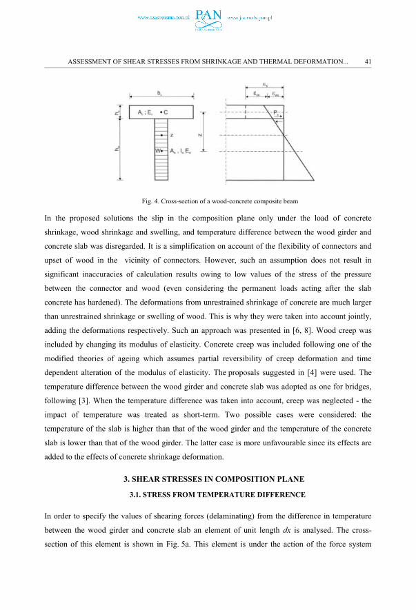
Fig. 4. Cross-section of a wood-concrete composite beam
In the proposed solutions the slip in the composition plane only under the load of concrete
shrinkage, wood shrinkage and swelling, and temperature difference between the wood girder and
concrete slab was disregarded. It is a simplification on account of the flexibility of connectors and
upset of wood in the vicinity of connectors. However, such an assumption does not result in
significant inaccuracies of calculation results owing to low values of the stress of the pressure
between the connector and wood (even considering the permanent loads acting after the slab
concrete has hardened). The deformations from unrestrained shrinkage of concrete are much larger
than unrestrained shrinkage or swelling of wood. This is why they were taken into account jointly,
adding the deformations respectively. Such an approach was presented in [6, 8]. Wood creep was
included by changing its modulus of elasticity. Concrete creep was included following one of the
modified theories of ageing which assumes partial reversibility of creep deformation and time
dependent alteration of the modulus of elasticity. The proposals suggested in [4] were used. The
temperature difference between the wood girder and concrete slab was adopted as one for bridges,
following [3]. When the temperature difference was taken into account, creep was neglected - the
impact of temperature was treated as short-term. Two possible cases were considered: the
temperature of the slab is higher than that of the wood girder and the temperature of the concrete
slab is lower than that of the wood girder. The latter case is more unfavourable since its effects are
added to the effects of concrete shrinkage deformation.
3. SHEAR STRESSES IN COMPOSITION PLANE
3.1. STRESS FROM TEMPERATURE DIFFERENCE
In order to specify the values of shearing forces (delaminating) from the difference in temperature
between the wood girder and concrete slab an element of unit length dx is analysed. The cross-
section of this element is shown in Fig. 5a. This element is under the action of the force system
ASSESSMENT OF SHEAR STRESSES FROM SHRINKAGE AND THERMAL DEFORMATION... 41

presented in Fig. 5b. To enable marking the acting forces, in the figure a space was left between
elements of the section, with an explanation that its value is zero. The force system shown in
Fig. 5b can be reduced to a system presented in Fig. 5c. Using the condition of equilibrium of forces
projection onto the horizontal axis we obtain:
(1)
hence:
(2)
Assuming the inseparability of the deformations of slab concrete and wood girder in the
composition plane, it can be assumed that shear stress tT (it can be defined as the intensity of an
elastic composition) is:
(3)
where:
cT – coefficient of the composition flexibility; it can be adopted as cT = 0,85 Ec [4],
uT – shift in the direction of the longitudinal axis of analysed section x in the composition plane.
Fig. 5. Composite beam: a – cross-section, b – forces system, c – reduced forces system
42 K. FURTAK

Using the given dependencies and taking into account the fact that the slab cross section is under
the action of a force applied to its edge (at the level of the composition plane) we obtain after
transformations:
(4)
Unit unrestrained thermal deformation is:
(5)
where:
αT - coefficient of thermal expansion,
ΔT – difference in the temperature between the concrete (RC) slab and wood girder.
The solution of equation (4) is the formula [4]:
(6)
where:
(7)
(8)
δw – stiffness index of the wood girder
(9)
δc – stiffness index of the concrete slab
(10)
Ew, Aw, Iw – modulus of elasticity of wood, cross section and moment of inertia of the wood girder,
Eco, Ac – initial modulus of elasticity of concrete (at time t = 0) and cross-sectional area of the concrete slab, z
– arm of interior forces.
The steady stress in the composition plane from the difference in temperature is:
(11)
The highest value of the above stress occurs at the ends of element (x = 0, x = 2l) and is:
(12)
ASSESSMENT OF SHEAR STRESSES FROM SHRINKAGE AND THERMAL DEFORMATION... 43

where:
l – half length of the element,
m – coefficient equal [4]:
(13)
k3c – coefficient covering the impact of time dependent change of modulus of elasticity of concrete:
(14)
c – concrete creep coefficient (time-dependent; consequently, also k3c is time-dependent).
3.2. STRESS FROM CONCRETE SHRINKAGE
The procedure of the calculation of stress from concrete shrinkage is similar to that of calculating
the stress from temperature difference. Then we obtain:
(15)
and
(16)
where:
(17)
(18)
k2c – coefficient covering concrete creep:
(19)
– unit unrestrained shrinkage deformation.
Taking into account the flexibility of the wood girder and concrete creep we finally obtain:
(20)
(21)
44 K. FURTAK

3.3. DEFORMATION FROM WOOD SHRINKAGE
Deformation from the shrinkage (and swelling) of wood can be calculated in a similar way as in the
calculation of deformation from concrete shrinkage. Another method (more favourable) is to add
algebraically the deformations from the unrestrained shrinkage of concrete and wood . Then,
the shrinkage deformation of wood is adopted with a sign opposite to the shrinkage deformation of
concrete, in the case of swelling with the same sign. Wood creep can be included by inserting in
formulae (20) and (21) the modified modulus of elasticity of wood Ewt
(22)
instead of the modulus of elasticity of concrete, where :
Ew0 – modulus of elasticity of wood at time t = 0,
k3w – coefficient the value of which can be calculated from formula:
(23)
creep coefficient for wood (its value is time dependent, so, consequently, coefficient k3w also is time
dependent).
4. ANALYSIS OF THE PROPOSED SOLUTION
The analysis of the proposed solutions was performed with the initial assumptions on the geometry
of the investigated composite girder as follows: bc = 1,00 m, hc = 0,20 m, Ec0 = 34 GPa,bw = 0,30
m, hw = 2,00 m, Ew0 = 12 GPa, Hence, Ac = 0,20 m2, Aw = 0,60 m2, Iw = 0,20 m4, z = 1,10 m.
The adopted boundary value of the creep coefficient of concrete was = 3,20, that of wood
= 0,60. The value of unrestrained shrinkage of concrete was adopted as equal to ,
that of wood (parallel to the fibres) . The same value can be adopted for wood
swelling. The assumption made in drawing the diagrams – which should be treated as an illustration
of the problem rather than a presentation of precise results of the analysis – was a similar time
course of the deformations from concrete shrinkage, and creep of concrete and wood, although the
real course is different (cf. Fig. 6). From the practical point of view, the adopted assumption is not
significant for the final values, for . With these assumptions we obtain:
, ,
,
m = 4,123.
ASSESSMENT OF SHEAR STRESSES FROM SHRINKAGE AND THERMAL DEFORMATION... 45

Fig. 6. Time course of relative (referred to the maximum ones) values of shrinkage deformations of concrete,
and the creep coefficient of concrete and wood [8]
A detailed analysis was performed for beams of the length of 2l = 15,00 m, 2l = 20,00 m, 2l = 25,00
m. The results of the analysis are shown in Fig. 7, 8 and 9. Fig. 7 illustrates the dependence of the
shear (delaminating) stresses between the concrete slab and wood girder depending on the beam
span. Fig. 8 illustrates a similar dependence, but on the X-axis a relative distance of the analysed
cross-section referred to the half span was adopted.
Fig. 7. Impact of beam span on shear (delaminating) stresses
46 K. FURTAK

Fig . 8. Impact of the location of the analysed cross-section relative to beam span on shear (delaminating) stresses
Fig . 9. Impact of the location of the analysed cross-section relative to beam span on the relative value (referred to the maximum one) of the shear (delaminating) stress
The diagram shown in Fig. 9 illustrates the dependence of the relative value of the delaminating
stress referred to the maximum value (for x = 0) depending on the relative distance (referred to
beam half span) of the analysed cross-section. It is practically a graphic presentation of the final
fraction of formula (11). Based on the results of the analysis of the proposed solutions it can be
stated that the value of the delamination stress highly depends on the beam span. The impact of the
parameters related to concrete shrinkage and creep and creep, shrinkage or swelling of wood
follows directly from the provided formulae. The effect of deformations from shrinkage or swelling
of wood can be added algebraically to the effect of shrinkage deformations of concrete. A separate
analysis was performed in the range of the impact of creep of concrete and wood. This impact can
be easily interpreted by the analysis of the second fraction of formula (11), with coefficients δ and
k2 in the denominator. If the results of calculations excluding creep are adopted as basic, then if
creep and the time-changed modulus of elasticity of concrete and wood are included, the value of
ASSESSMENT OF SHEAR STRESSES FROM SHRINKAGE AND THERMAL DEFORMATION... 47

the delaminaing stress will be reduced by 37,85%. The effect of the creep of wood is but minor and
is less than 10% . The thermal deformations are According to [3], the difference in
temperature is 13oC when the slab is heated 3,5oC at the slab load relative to the wood girder.
Although in the case of slab heating higher values of ΔT are adopted, it should be noted that this
effect is not subtracted from the shrinkage deformation of the concrete slab. The reliable value of
the thermal deformation is This deformation is considerably lower than
that from concrete shrinkage. The value of the shear stress between the concrete slab and glulam
girder is also affected by the girder’s height. The results of analysis in this area are shown in
Fig. 10. The curves were plotted for the beam span of 2l = 15,00 m. The solid line indicates the
girder of hw = 2,00 m in height, while the broken line refers to the girder of the height of hw = 1,50
m. The values of the stress lower by ca. 18% are found in the case of a lower girder. This results
from a lower resistance of the girder against concrete shrinkage.
Fig. 10. Shear (delaminating) stress for various heights of wood girders
5. REMARKS AND FINAL CONCLUSIONS
The aim of the paper is to assess the values of shear (delaminating) stress in the composition plane
between the concrete (RC) deck slab and wood girder from concrete shrinkage, and shrinkage and
swelling of wood, as well as difference in temperature between the wood web and concrete slab.
The analysis was performed for concrete-wood composite beams, on elements characteristic of
bridges. The creep of concrete and wood were also taken into account. The study has shown that the
value of the stresses discussed is heavily affected by the composite beam span. Moreover, based on
the analysis of the provided formulae, the impact of geometric parameters and the value of
unrestrained shrinkage on delaminating stresses can be specified. These may be higher than the
natural adhesion of concrete to wood (glued laminated timber). The reduction in the value of the
48 K. FURTAK

stresses from concrete shrinkage results from concrete creep. The effect of wood creep and the
stress from the shrinkage or swelling of wood is significantly lower. In practical applications the
deformation from concrete shrinkage can be added to that from wood swelling. The case is reverse
for wood shrinkage, where these deformations should be subtracted from those from concrete
shrinkage. The impact of the difference in temperature ΔT between the concrete (RC) slab and
wood girder is much lower than that of concrete shrinkage. This results from the values of ΔT
recommended in the Eurocode [3]. In the case of delaminating stresses from ΔT the creep of
concrete and wood is disregarded assuming that the impact of temperature difference is short-term
although repeated many times.
REFERENCES
[1] Biliszczuk J., Bień J., Maliszkiewicz P.: Mosty z drewna klejonego. [Bridges from glued laminated timber.] Wydawnictwa Komunikacji i Łączności. Warszawa, 1988 [in Polish]. [2] EN 1995-1-1. Projektowanie konstrukcji drewnianych. Zasady generalne i zasady dla budynków. [Design of timber structures. General - Common rules and rules for buildings.][3] EN 1995-2. Projektowanie mostów drewnianych. [Design of timber structures.] [4] Furtak K.: Mosty zespolone. [Composite bridges.] PWN. Warszawa 1999 [in Polish]. [5] Furtak K.: Mosty drewniane.[ Timbers bridges.] Politechnika Krakowska 2002 [in Polish]. [6] Gelfi P., Giuriani E., Marini A.: Stud Shear Connection Design for Composite Concrete Slab and Wood Beams. Journal of Structural Engineering. December 2002. [7] Holschemacher K., Klotz S., Köhler S.: Verbunddecken aus Stahlfaserbeton und Holz. Beton- und Stahlbetonbau, 99 (2004), Heft 1. [8] Kuhlmann U., Schänzlin J., Michelfelder B.: Berechnung von Holz-Beton-Verbunddecken. Beton- und Stahlbetonbau, 99 (2004), Heft 4. [9] Resch E., Schmidt J., Kaliske M., Schneider W.: Betrachtungen zur Verkehrslastannahme bei Holzbalken/Beton-Verbunddecken. Beton- und Stahlbetonbau, 99 (2004), Heft 10. [10] Steinberg E., Selle R.,Faust T.: Connectors for Timber-Lightweight Concrete Composite Structures. Journal of Structural Engineering. November 2003. [11] Szumigała M., Chybiński M., Polus Ł.: Preliminary Analysis of the Aluminum-Timber Composite Beams. Civil and Environmental Engineering Reports. 2017. [12] Zobel H., Alkhafaji T.: Mosty drewniane. [Timbers bridges.] Wydawnictwa Komunikacji i Łączności.
Warszawa 2006 [in Polish].
LIST OF FIGURES
Figure 1. Examples of cross-sections of glued laminated timber – concrete composite bridges [1]: a –standard cross-section, b – girders from glulam, c – girders from prestressed glulam Rysunek 1. Przykładowe przekroje poprzeczne mostów o konstrukcji zespolonej typu drewno klejone –beton [1]: a – przekrój typowy, b – dźwigary drewniane z drewna klejonego, c – dźwigary ze sprężonego
drewna klejonego
ASSESSMENT OF SHEAR STRESSES FROM SHRINKAGE AND THERMAL DEFORMATION... 49

Figure 2. Deformations of composite beams induced by: a – concrete shrinkage, b – wood shrinkage, c –wood swelling Rysunek 2. Odkształcenia belek zespolonych pod wpływem: a – skurczu betonu, b – skurczu drewna, c –pęcznienia drewna
Figure 3. Deformations of composite beams caused by temperature difference between wood girder and concrete (RC) beamRysunek 3. Odkształcenia belek zespolonych pod wpływem różnicy temperatury między dźwigarem
drewnianym i płytą betonową
Figure 4. Cross-section of a wood-concrete composite beam Rysunek 4. Przekrój poprzeczny belki zespolonej typu drewno-beton Figure 5. Composite beam: a – cross-section, b – forces system, c – reduced forces system Rysunek 5. Belka zespolona: a – przekrój poprzeczny, b – układ sił, c – zredukowany układ sił
Figure 6. Time course of relative (referred to the maximum ones) values of shrinkage deformations of concrete, and the creep coefficient of concrete and wood. Rysunek 6. Przebieg w czasie względnych (odniesionych do maksymalnych) wartości odkształceń
skurczowych betonu oraz współczynnika pełzania betonu i drewna
Figure 7. Impact of beam span on shear (delaminating) stresses Rysunek 7. Wpływ rozpiętości belki na wartość naprężeń ścinających (rozwarstwiających)
Figure 8. Impact of the location of the analysed cross-section relative to beam span on shear (delaminating) stresses Rysunek 8. Wpływ położenia rozpatrywanego przekroju względem rozpiętości belki na wartość naprężeń
ścinających (rozwarstwiających)
Figure 9. Impact of the location of the analysed cross-section relative to beam span on the relative value (referred to the maximum one) of the shear (delaminating) stress Rysunek 9. Wpływ położenia przekroju względem rozpiętości belki na wartość względną (odniesioną do
maksymalnej) naprężenia ścinającego (rozwarstwiającego)
Figure 10. Shear (delaminating) stress for various heights of wood girders Rysunek 10. Porównanie wartości naprężeń ścinających (rozwarstwiających) dla różnych wysokości
dźwigarów drewnianych
Received 15.06.2019
Revised 26.06.2019
50 K. FURTAK