at control operation manual gb - aqua medic system set-manual-eng_13764624632.pdf · at control...
TRANSCRIPT
1
AT Control
Operation Manual GB
AT Control is a measuring and controlling system with nearly unlimited possibilities for the electronic
control of aquariums and terrariums. The basic version comprises a temperature controller, multiple
timer functions and a PC connection for programming and data display. Optional accessories are a
pH control, Redox (ORP) control, density control (for marine aquariums), conductivity control (for
pure and fresh water) and a level control. The parameter can be connected and set points can be
adjusted as fix points or as a curve in the day-night-cycle. The complete programming can be made
via the Controller or directly via the keyboard of the PC.
GmbH
Gewerbepark 24, 49143 Bissendorf, Germany ____________________________________________________________________________________________
2
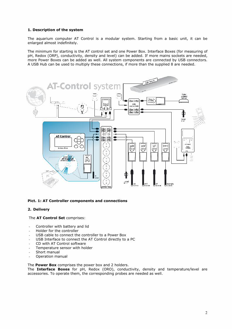
1. Description of the system
The aquarium computer AT Control is a modular system. Starting from a basic unit, it can be
enlarged almost indefinitely.
The minimum for starting is the AT control set and one Power Box. Interface Boxes (for measuring of
pH, Redox (ORP), conductivity, density and level) can be added. If more mains sockets are needed,
more Power Boxes can be added as well. All system components are connected by USB connectors.
A USB Hub can be used to multiply these connections, if more than the supplied 8 are needed.
Pict. 1: AT Controller components and connections
2. Delivery The AT Control Set comprises:
- Controller with battery and lid
- Holder for the controller
- USB cable to connect the controller to a Power Box
- USB Interface to connect the AT Control directly to a PC
- CD with AT Control software
- Temperature sensor with holder
- Short manual
- Operation manual
The Power Box comprises the power box and 2 holders. The Interface Boxes for pH, Redox (ORO), conductivity, density and temperature/level are accessories. To operate them, the corresponding probes are needed as well.
3
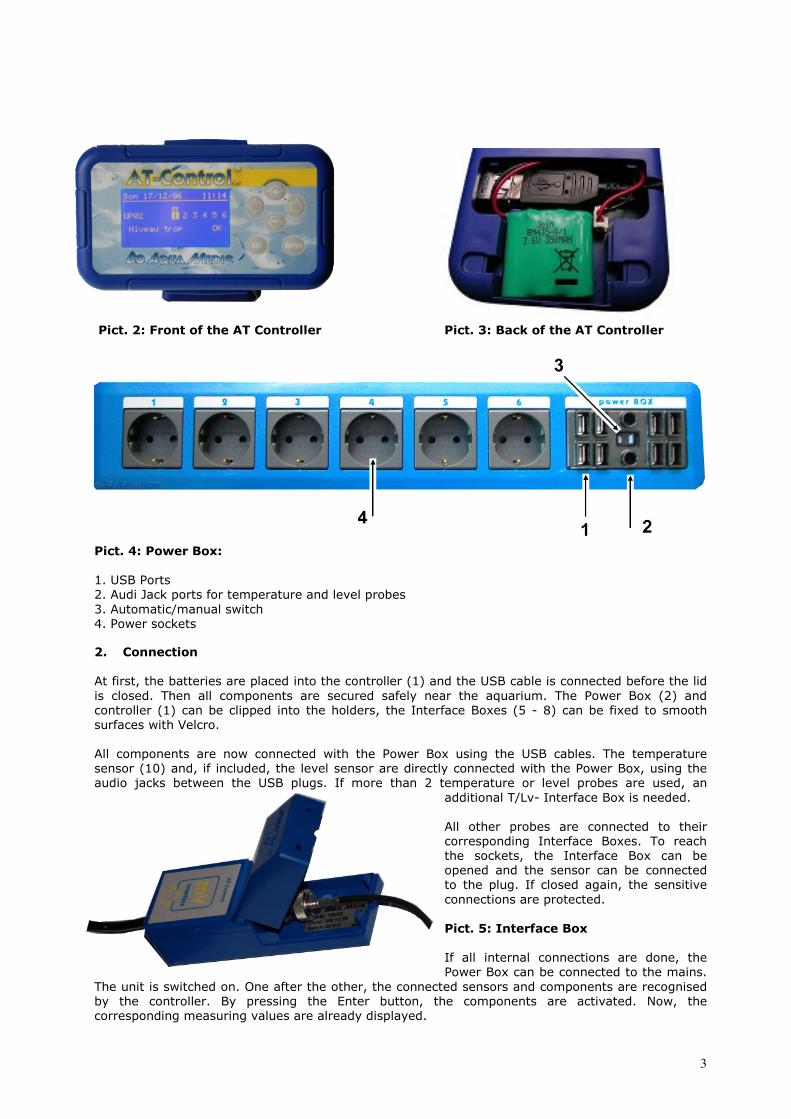
Pict. 2: Front of the AT Controller Pict. 3: Back of the AT Controller
Pict. 4: Power Box:
1. USB Ports
2. Audi Jack ports for temperature and level probes
3. Automatic/manual switch
4. Power sockets
2. Connection At first, the batteries are placed into the controller (1) and the USB cable is connected before the lid
is closed. Then all components are secured safely near the aquarium. The Power Box (2) and
controller (1) can be clipped into the holders, the Interface Boxes (5 - 8) can be fixed to smooth
surfaces with Velcro.
All components are now connected with the Power Box using the USB cables. The temperature
sensor (10) and, if included, the level sensor are directly connected with the Power Box, using the
audio jacks between the USB plugs. If more than 2 temperature or level probes are used, an
additional T/Lv- Interface Box is needed.
All other probes are connected to their
corresponding Interface Boxes. To reach
the sockets, the Interface Box can be
opened and the sensor can be connected
to the plug. If closed again, the sensitive
connections are protected.
Pict. 5: Interface Box
If all internal connections are done, the
Power Box can be connected to the mains.
The unit is switched on. One after the other, the connected sensors and components are recognised
by the controller. By pressing the Enter button, the components are activated. Now, the
corresponding measuring values are already displayed.

4
3. List of Icons used in the controller The Icons are displayed in the screen of the controller directly above the sockets and at the left
lower corner.
Attention, an alarm value is over/under
the limits. Socket wave effect
Manual operation.
Socket tide effect
Function button is activated.
Socket
RX Redox (ORP) socket is active (on).
Agenda
pH pH socket is active (on).
Agenda with sound alarm
µS Conductivity or density socket is active
(on).
Summer mode
Timer socket active (on).
Sound alarm activated
Temperature socket is active (on).
Power Box manually blocked (switch on
“man”).
Level socket is active (on).
Socket blocked by blackout
Level socket is blocked. ? Unknown accessory
5. Connection of the AT Control to a PC
For connecting the AT Control to a PC, an IBM compatible PC is needed.
The USB Interface is connected to the Power Box with the USB cable that is included in the Interface
Box and the other side to the USB socket of a PC or laptop. Do not mix the USB cables. They are
marked on the Interface. A standard USB cable, up to 10 m of length may be used as well.
Now, the AT Control Software has to be installed on the PC by the delivered CD. The program
creates an icon on the desktop. After the start of the program, the display shows at the lower edge:
“not connected”. At the upper edge of the display, a row of icons is placed among the AB logo. By
pressing this button, the connection between AT Control and PC is performed. Make sure that the AT
control is showing the basic screen with the measuring values. If other screens are active, the
connection is not successful. The rest of the programming is self explaining and explained in a
special manual.
6. Overview about the menu of the AT Control
Main menu
Page
• Language
•
German
English
7
• Date/Time Time
Date
7
• Graphic period Temperature
pH value
Redox (ORP)
Density
Conductivity
7
• Password 8
• Display Brightness
Contrast
Screen Mode
Scrolling Time
8
8
8
9
• Reset settings 9
Settings
• About 9

5
• Change Name Power Box
Plugs
10
11
• Manual Commands 11
• Program Timer 12
• Wave effect 13
• Tide effect 14
• Power Cut 14
• Summer function 14
Power Box
• About 14
Function Keys 15
Agenda 17
Temperature* • Change name
• Programs
• Data record
• Alarm
• Calibrate Sensor
• Measuring unit
• Remove temperature
sensor
• About
18
18
19
20
20
20
21
21
Level * • Change name
• Programs
• Alarm
• Measuring unit
• Remove level sensor
• About
21
22
22
22
23
24
pH value* • Change name
• Programs
• Data record
• Alarm
• Calibrate Sensor
• Remove pH sensor
• About
25
25
26
26
26
27
27
Redox (ORP)* • Change name
• Programs
• Data record
• Alarm
• Calibrate Sensor
• Remove Redox sensor
• About
28
28
29
29
29
30
30
Density* Conductivity*
• Change name
• Programs
• Data record
• Alarm
• Calibrate Sensor
• Measuring unit
• Remove density sensor
• About
31
31
32
32
32
33
33
33
Ethernet Module
• 33
Water leakage • Interface
• Sensor
41
44
* Is only displayed if the corresponding sensor is connected.
6
7. Programming There are 2 possibilities to program the AT Control. If The AT Control is connected to a PC, the
complete programming can be performed via the keyboard of the PC. The AT Control Software has
to be installed before the unit can be connected to the PC. It is also possible to program the AT
control via the buttons of the controller.
Programming the AT Control via the buttons on the controller
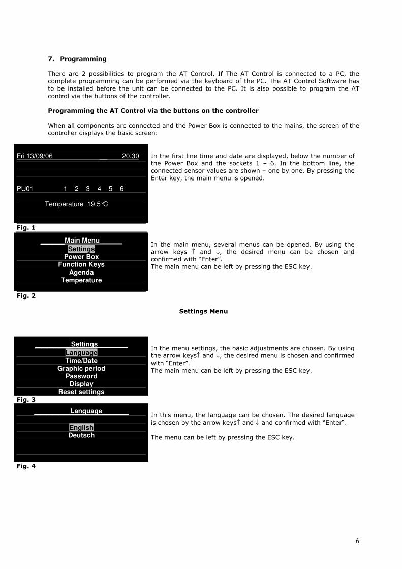
When all components are connected and the Power Box is connected to the mains, the screen of the
controller displays the basic screen:
Fri 13/09/06 __ 20.30
PU01 1 2 3 4 5 6 Temperature 19,5°C
In the first line time and date are displayed, below the number of
the Power Box and the sockets 1 – 6. In the bottom line, the
connected sensor values are shown – one by one. By pressing the
Enter key, the main menu is opened.
Fig. 1
____Main Menu______
Settings Power Box
Function Keys Agenda
Temperature
In the main menu, several menus can be opened. By using the
arrow keys ↑ and ↓, the desired menu can be chosen and
confirmed with “Enter”.
The main menu can be left by pressing the ESC key.
Fig. 2
Settings Menu
______Settings________
Language Time/Date
Graphic period Password
Display Reset settings
In the menu settings, the basic adjustments are chosen. By using the arrow keys↑ and ↓, the desired menu is chosen and confirmed
with “Enter”.
The main menu can be left by pressing the ESC key.
Fig. 3
______Language_______
English Deutsch
In this menu, the language can be chosen. The desired language is chosen by the arrow keys↑ and ↓ and confirmed with “Enter“.
The menu can be left by pressing the ESC key.
Fig. 4

7
____Time/Date______
Time: 19: 55 Date: 02/10/06
In this menu, time and date can be adjusted. With the arrow keys ↑ and ↓ the desired values can be chosen. The cursor is moved
with the ← and → keys to the next number.
The menu can be left by pressing the ESC key.
Fig. 5
_Graphic period
Temperature pH
Redox (ORP) Density
In this menu, it is confirmed how long the data of the single
parameters are saved. With the arrow keys, the desired
parameter is chosen (e.g. temperature) and confirmed with
“Enter”. The saved values can be displayed in the menus of the
parameter (temperature menu, pH menu) in the line “Data
Record”.
Fig. 6
_____Graphic period ___
Days: 07
In this screen, the period can be chosen from 3 different standard
periods: 1 day, one week (7 days) or one month (30 days). This
period can be adjusted individually for each parameter. For the
better display at the screen (esp. if connected to a PC) we
recommend to use the same period for all parameters.
The menu can be left by pressing the ESC key.
Fig. 7
______Password_______
Activated PIN
With this menu, the AT control can be protected with a password
against undesired changes by accident or on purpose!
Move the cursor to “activate PIN” and press “Enter”.
The menu can be left by pressing the ESC key.
Fig. 8
Activate PIN
Off
Waiting Time 01 Minute
By pressing the ↑ - key and confirming with “Enter“, a screen is
opened asking for a PIN. With the arrow keys, the PIN can be
created as a combination of the numbers 0, 1, 2 and 3. After
pressing “Enter”, the key has to be repeated and then it is
activated.
Fig. 9
_____Display_______
Brightness Contrast
Screen Mode Scrolling Time
In this menu, the different properties of the display can be
adjusted. The cursor is moved to the desired line and confirmed
with “Enter”.
The menu can be left by pressing the ESC key.
Fig. 10

8
______Brightness______
In this menu, the brightness of the screen can be adjusted. Therefore, the ↑ and↓ keys are pressed until the desired
brightness is reached. Confirm with “Enter”.
The menu can be left by pressing the ESC key.
Fig. 11
____Contrast_____
In this menu, the contrast of the screen can be adjusted. Therefore, the ↑ and↓ keys are pressed until the desired contrast
is reached. Confirm with “Enter”.
The menu can be left by pressing the ESC key.
Fig. 12
____ Screen Mode_____
Always on Stand by
In this menu, the display mode can be adjusted. In the “always
on” mode, the display is illuminated continuously, in the stand-by
mode the screen is switched off after 3 minutes after the last
pressing of a key. To switch it on again, press any key. You can choose between “always on” and “stand by” with the ↑ and↓ keys
and confirm with “Enter”.
The menu can be left by pressing the ESC key.
Fig. 13
_____Scrolling time____
Seconds: 05
In the basic screen, the display switches from one parameter to
the next every some seconds – the scrolling time. In this menu,
this time can be adjusted. The basic setting is 5 sec. It can be
changed with the arrow keys, confirmed with Enter.
The menu can be left by pressing the ESC key.
Fig. 14
Would you like to reset all settings?
Enter: confirm Esc: cancel
In this menu, all settings can be re-set to the pre-set values. Just
move the arrow keys to confirm and press Enter.
The menu can be left by pressing the ESC key.
Fig. 15
Version FW 1.1 Version HW: 1.23
Press any key to continue
“About“
This last screen of the settings menu shows the firmware and
hardware versions that are installed.
Fig. 16
9
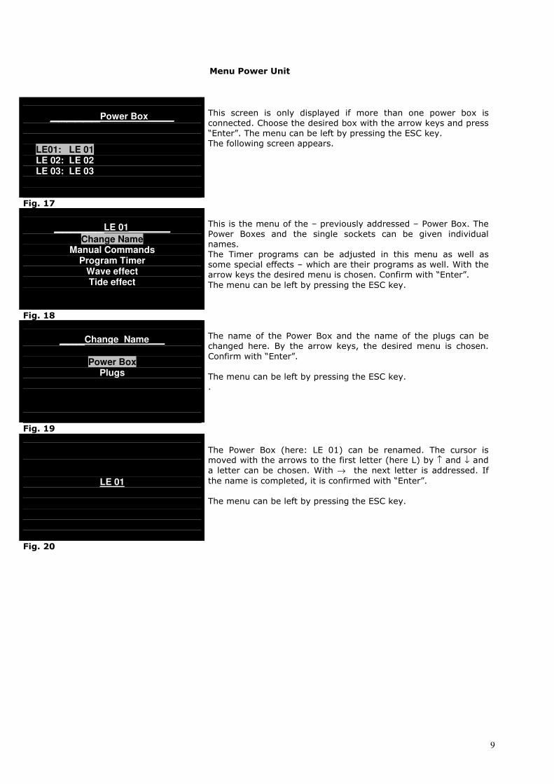
Menu Power Unit
______Power Box_____
LE01: LE 01 LE 02: LE 02 LE 03: LE 03
This screen is only displayed if more than one power box is
connected. Choose the desired box with the arrow keys and press
“Enter”. The menu can be left by pressing the ESC key.
The following screen appears.
Fig. 17
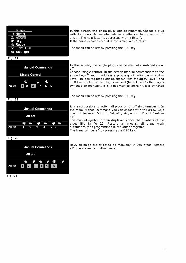
______LE 01________
Change Name Manual Commands
Program Timer Wave effect Tide effect
This is the menu of the – previously addressed – Power Box. The
Power Boxes and the single sockets can be given individual
names.
The Timer programs can be adjusted in this menu as well as
some special effects – which are their programs as well. With the
arrow keys the desired menu is chosen. Confirm with “Enter”.
The menu can be left by pressing the ESC key.
Fig. 18
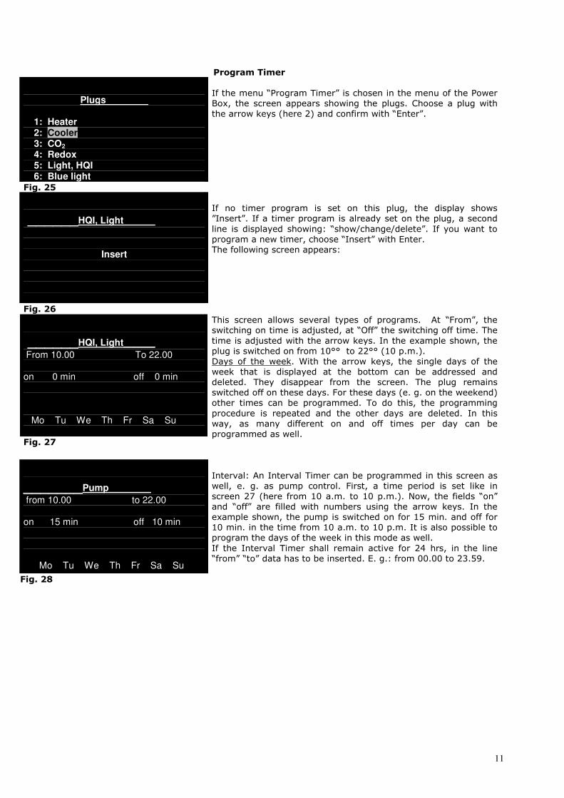
___Change Name___
Power Box
Plugs
The name of the Power Box and the name of the plugs can be
changed here. By the arrow keys, the desired menu is chosen.
Confirm with “Enter”.
The menu can be left by pressing the ESC key.
.
Fig. 19
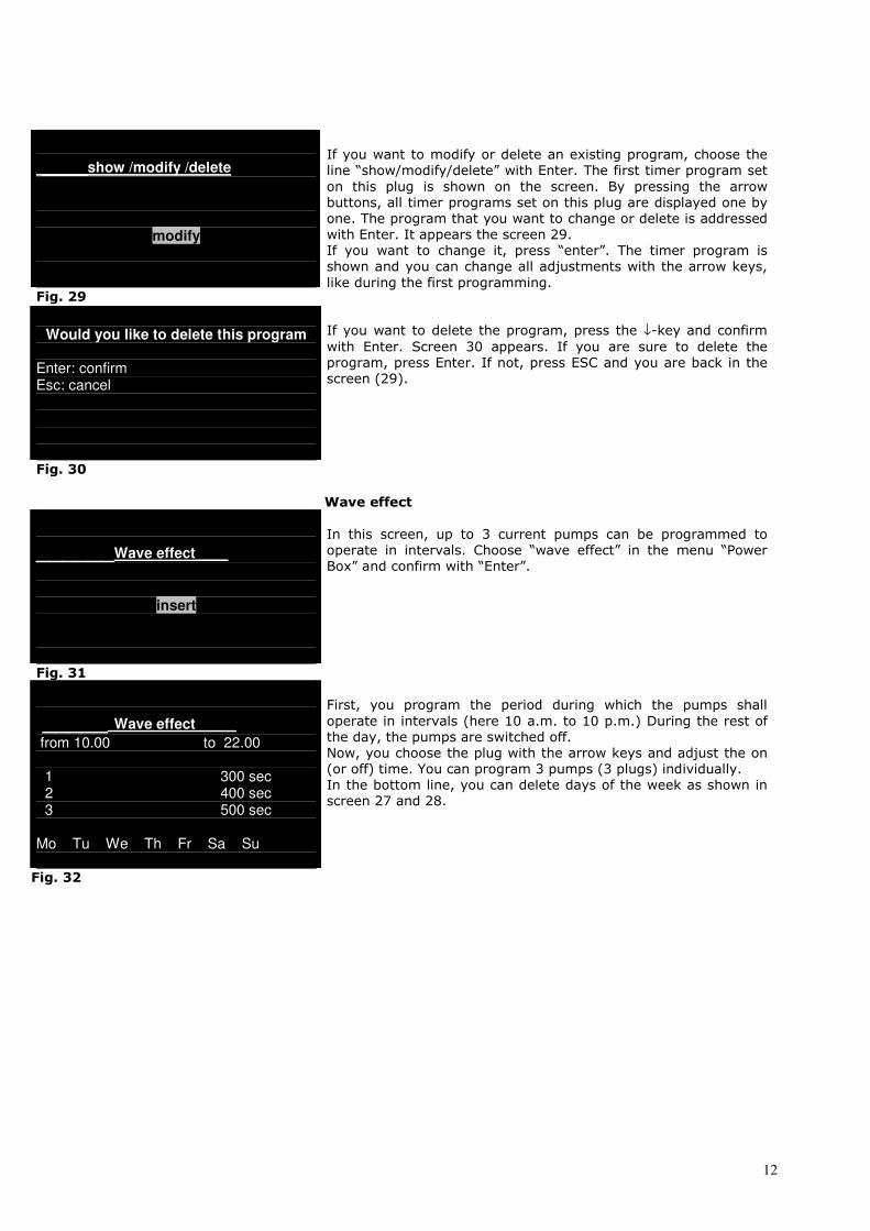
LE 01
The Power Box (here: LE 01) can be renamed. The cursor is moved with the arrows to the first letter (here L) by ↑ and ↓ and
a letter can be chosen. With → the next letter is addressed. If
the name is completed, it is confirmed with “Enter”.
The menu can be left by pressing the ESC key.
Fig. 208
10
Plugs____ 1: Heater 2: Cooler 3: CO2 4: Redox 5: Light, HQI 6: Bluelight
In this screen, the single plugs can be renamed. Choose a plug with the cursor. As described above, a letter can be chosen with ↑
and ↓ . The next letter is addressed with → Enter“.
If the name is completed, it is confirmed with “Enter”.
The menu can be left by pressing the ESC key.
Fig. 21
Manual Commands
Single Control
PU 01 1 2 3 4 5 6
In this screen, the single plugs can be manually switched on or
off.
Choose “single control” in the screen manual commands with the
arrow keys ↑ and ↓. Address a plug e.g. (1) with the → and ←
keys. The desired mode can be chosen with the arrow keys ↑ and
↓: If the number of the plug is marked (here 1 and 3) the plug is
switched on manually, if it is not marked (here 4), it is switched
off.
The menu can be left by pressing the ESC key.
Fig. 22
Manual Commands
All off
PU 01 1 2 3 4 5 6
It is also possible to switch all plugs on or off simultaneously. In
the menu manual command you can choose with the arrow keys ↑ and ↓ between “all on”, “all off”, single control” and “restore
all”.
The manual symbol in then displayed above the numbers of the
plugs like in fig 22. Restore all means, all plugs work
automatically as programmed in the other programs.
The Menu can be left by pressing the ESC key.
Fig. 23
Manual Commands
All on
PU 01 1 2 3 4 5 6 1
Now, all plugs are switched on manually. If you press “restore
all”, the manual icon disappears.
Fig. 24
11
Program Timer
Plugs________
1: Heater 2: Cooler 3: CO2 4: Redox 5: Light, HQI 6: Blue light
If the menu “Program Timer” is chosen in the menu of the Power
Box, the screen appears showing the plugs. Choose a plug with
the arrow keys (here 2) and confirm with “Enter”.
Fig. 25
______HQI, Light______
Insert
If no timer program is set on this plug, the display shows
”Insert”. If a timer program is already set on the plug, a second
line is displayed showing: “show/change/delete”. If you want to
program a new timer, choose “Insert” with Enter.
The following screen appears:
Fig. 26
______HQI, Light______
From 10.00 To 22.00 on 0 min off 0 min Mo Tu We Th Fr Sa Su Fig. 27
This screen allows several types of programs. At “From”, the
switching on time is adjusted, at “Off” the switching off time. The
time is adjusted with the arrow keys. In the example shown, the
plug is switched on from 10°° to 22°° (10 p.m.).
Days of the week. With the arrow keys, the single days of the
week that is displayed at the bottom can be addressed and
deleted. They disappear from the screen. The plug remains
switched off on these days. For these days (e. g. on the weekend)
other times can be programmed. To do this, the programming
procedure is repeated and the other days are deleted. In this
way, as many different on and off times per day can be
programmed as well.
_______Pump________
from 10.00 to 22.00 on 15 min off 10 min Mo Tu We Th Fr Sa Su
Interval: An Interval Timer can be programmed in this screen as
well, e. g. as pump control. First, a time period is set like in
screen 27 (here from 10 a.m. to 10 p.m.). Now, the fields “on”
and “off” are filled with numbers using the arrow keys. In the
example shown, the pump is switched on for 15 min. and off for
10 min. in the time from 10 a.m. to 10 p.m. It is also possible to
program the days of the week in this mode as well.
If the Interval Timer shall remain active for 24 hrs, in the line
“from” “to” data has to be inserted. E. g.: from 00.00 to 23.59.
Fig. 28
12
____show /modify /delete
modify
Fig. 29
If you want to modify or delete an existing program, choose the
line “show/modify/delete” with Enter. The first timer program set
on this plug is shown on the screen. By pressing the arrow
buttons, all timer programs set on this plug are displayed one by
one. The program that you want to change or delete is addressed
with Enter. It appears the screen 29.
If you want to change it, press “enter”. The timer program is
shown and you can change all adjustments with the arrow keys,
like during the first programming.
Would you like to delete this program
Enter: confirm Esc: cancel
If you want to delete the program, press the ↓-key and confirm
with Enter. Screen 30 appears. If you are sure to delete the
program, press Enter. If not, press ESC and you are back in the
screen (29).
Fig. 30
Wave effect
______Wave effect____
insert
In this screen, up to 3 current pumps can be programmed to
operate in intervals. Choose “wave effect” in the menu “Power
Box” and confirm with “Enter”.
Fig. 31
_____ Wave effect_____
from 10.00 to 22.00
1 300 sec 2 400 sec 3 500 sec
Mo Tu We Th Fr Sa Su
First, you program the period during which the pumps shall
operate in intervals (here 10 a.m. to 10 p.m.) During the rest of
the day, the pumps are switched off.
Now, you choose the plug with the arrow keys and adjust the on
(or off) time. You can program 3 pumps (3 plugs) individually.
In the bottom line, you can delete days of the week as shown in
screen 27 and 28.
Fig. 32
13
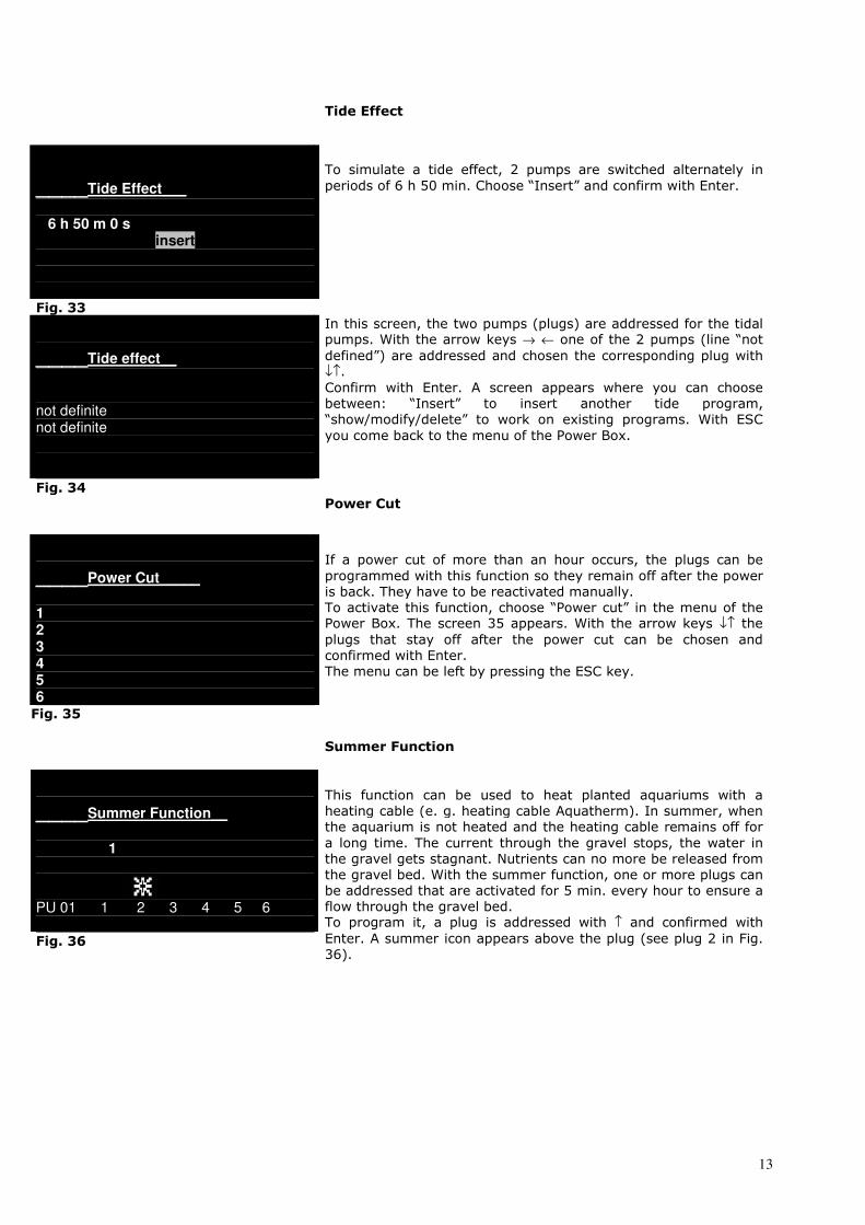
Tide Effect
____Tide Effect___
6 h 50 m 0 s insert
To simulate a tide effect, 2 pumps are switched alternately in
periods of 6 h 50 min. Choose “Insert” and confirm with Enter.
Fig. 33
____Tide effect__
not definite not definite
In this screen, the two pumps (plugs) are addressed for the tidal pumps. With the arrow keys → ← one of the 2 pumps (line “not
defined”) are addressed and chosen the corresponding plug with ↓↑.
Confirm with Enter. A screen appears where you can choose
between: “Insert” to insert another tide program,
“show/modify/delete” to work on existing programs. With ESC
you come back to the menu of the Power Box.
Fig. 34
Power Cut
____Power Cut_____
1 2 3 4 5 6
If a power cut of more than an hour occurs, the plugs can be
programmed with this function so they remain off after the power
is back. They have to be reactivated manually.
To activate this function, choose “Power cut” in the menu of the Power Box. The screen 35 appears. With the arrow keys ↓↑ the
plugs that stay off after the power cut can be chosen and
confirmed with Enter.
The menu can be left by pressing the ESC key.
Fig. 35
Summer Function
____Summer Function__
1
PU 01 1 2 3 4 5 6
Fig. 36
This function can be used to heat planted aquariums with a
heating cable (e. g. heating cable Aquatherm). In summer, when
the aquarium is not heated and the heating cable remains off for
a long time. The current through the gravel stops, the water in
the gravel gets stagnant. Nutrients can no more be released from
the gravel bed. With the summer function, one or more plugs can
be addressed that are activated for 5 min. every hour to ensure a
flow through the gravel bed. To program it, a plug is addressed with ↑ and confirmed with
Enter. A summer icon appears above the plug (see plug 2 in Fig.
36).

14
Function keys
____Func. Keys______
↓ :
↑↑↑↑ :
→ :
← :
In the menu function keys, functions can be defined and addressed to arrow keys → ← and ↓↑. These functions are the
switching on and off of plugs or groups of plugs for a defined time
period (e. g. feeding break) or up to a manual command
(maintenance break).
The functions can be activated by pressing the corresponding
arrow key for 2 sec.
To insert them, the function “Function Key” is addressed with the
cursor and confirmed with Enter. The screen (Fig 37) appears. With the arrow keys ↓↑- the cursor is moved to the desired arrow,
where a function shall be inserted. Fig. 37
____Feeding break_____
Mode: off PU 01 1 2 3 4 5 6
Fig. 38 ____ Feeding break_____
Mode: time Max time : 0 h:20 m:0 s
PU 01 1 2 3 4 5 6
Fig. 39
In this screen, the function is first named here: “feeding break”. To name it, the arrow keys ↓↑ are used to define the letter and
the → ← keys to switch to the next letter. Confirm the name with
Enter.
The Cursor jumps to “off”. Here, the mode of the function can be chosen with the ↓↑ keys: “off”, “time”, “switch”, “hold”.
- off: The function key is switched off. - Time: By pressing the function key, a plug or a combination
of plugs will be switched off or on for a certain period of time.
If the time is over, it switches back automatically. With this
function, pumps can be switched off for some minutes for
feeding the fish without currents. If the mode is confirmed with →, the cursor jumps to “Max. Time”. Now, the period can
be chosen with the ↓↑-keys that the plugs shall be switched
on or off. If the time period is adjusted, press → to go to the
line with the plugs. The desired plug can be addressed with the → ← keys. The desired function can be chosen with the ↓↑
keys. An arrow icon appears above the chosen plug. If the
number of the plug is marked, the plug is switched on when
you press the function key. If it is not marked, the plug is
switched on for the programmed period when the function
key is activated. In our example (Fig. 39), the plugs 1 and 2 are switched on for 20 min. and the plugs 4 and 6 are switched off for 20 min. when the function key ↑ is activated.
____Light on ______
Mode: Hold
PU 01 1 2 3 4 5 6
- Switch: If the mode for the function key is adjusted to “switch”, the defined plugs are switched on or off -
depending, if the number below the arrow is marked or not -
after pressing the function key.
- Hold: If the mode is switched to hold, the plugs are activated (or deactivated, depending if the number below the arrow is
marked or not) only as long as the function key is pressed.
Fig. 40 If the function key is activated, the function icon is shown in
the main menu in the left corner at the bottom.
15
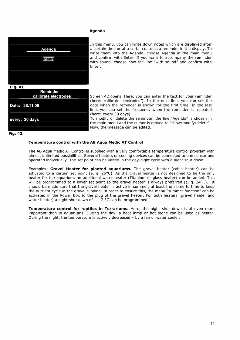
Agenda
____Agenda ______
Insert
In this menu, you can write down notes which are displayed after
a certain time or at a certain date as a reminder in the display. To
write them into the Agenda, choose Agenda in the main menu
and confirm with Enter. If you want to accompany the reminder
with sound, choose now the line “with sound” and confirm with
Enter.
Fig. 41 Reminder
______calibrate electrodes___ Date: 28.11.06 every: 30 days
Screen 42 opens. Here, you can enter the text for your reminder
(here: calibrate electrodes”). In the next line, you can set the
date when the reminder is shown for the first time. In the last
line, you can set the frequency when the reminder is repeated
(here: every 30 days).
To modify or delete the reminder, the line “Agenda” is chosen in
the main menu and the cursor is moved to “show/modify/delete”.
Now, the message can be edited.
Fig. 42 Temperature control with the AB Aqua Medic AT Control
The AB Aqua Medic AT Control is supplied with a very comfortable temperature control program with
almost unlimited possibilities. Several heaters or cooling devices can be connected to one sensor and
operated individually. The set point can be varied in the day-night cycle with a night shut down.
Examples: Gravel Heater for planted aquariums. The gravel heater (cable heater) can be adjusted to a certain set point (e. g. 25°C). As the gravel heater is not designed to be the only
heater for the aquarium, an additional water heater (Titanium or glass heater) can be added. This
will be programmed to a lower set point so the gravel heater is always preferred (e. g. 24°C). It
should be made sure that the gravel heater is active in summer, at least from time to time to keep
the nutrient cycle in the gravel running. In order to ensure this, the menu “summer function” can be
activated in the Power Box to the plug of the gravel heater. For both heaters (gravel heater and
water heater) a night shut down of 1 – 2 °C can be programmed.
Temperature control for reptiles in Terrariums. Here, the night shut down is of even more important than in aquariums. During the day, a heat lamp or hot stone can be used as heater.
During the night, the temperature is actively decreased – by a fan or water cooler.

16
Temperature menu
____Temperature______
Change Name Programs
Data Record Alarm
Calibrate Sensor Measuring units
About
Fig. 43
To enter the temperature menu, choose the corresponding line in
the main menu and confirm with Enter. In this menu, you can
program a temperature control – if you have connected at lest
one temperature sensor. Screen 43 opens. With the arrow keys
↓↑ you can choose the desired line and confirm with Enter.
“Change Name”. Here, you can change the name (e. g. to “temp aquarium1”). To do this, choose the first line and confirm.
“Temperature” is displayed. The first letter flashes. With the arrow keys ↓↑ you can choose a new letter. With the → ←- keys,
you get to the next letter. If the new name is completed, confirm
with Enter.
____Temperature______
Insert
Fig. 44
______Programs_______
Ref. 23.4°C
∆ MIN: ∆Max: 0.0°C 0.0°C plugs confirm
Programs: Choose in the upper screen “programs” and screen 44 opens. Choose “Insert” to insert a program. If programs are
already existing, a second line “show/modify/delete” is displayed.
Choose this line to edit an existing temperature program.
Insert a set point for temperature: If you choose “Insert screen 45 opens, the line “Ref.” is flashing.
Here, you can edit the desired value for the set point. The actual
temperature is displayed in °C. With Enter, you come to the
reference value. You can change the value to the desired point with the arrow keys ↓↑. Confirm with Enter.
Now, the line ∆ min. flashes. With the arrow keys ↓↑ , you can
add a value for the minimum deviation e. g. 0.2°C. If the actual
temperature decreases below the set point for 0.2°C, the plug is switched on for the heater. With the → ←- keys, you get to the ∆
max. value for the cooler. If you have these 2 values (the
hysteresis), confirm with Enter. Now, you can program the plugs
(see screen 46).
Fig. 45

17
2
UP01 1 2 3 4 5 6
UP01 1 2 3 4 5 6
Fig. 46
______Programs________
curve
∆ MIN: ∆Max: 0.0°C 0.0°C plugs confirm
In screen 46, the plugs for the heater or cooler are programmed. The chosen plug is marked (here No. 2). With the arrow keys →
← you can move the cursor to the desired plug. The upper line of
plugs is for the cooler, the lower line for the heater.
To program a heater on plug 2, press the arrow key ↓. The
thermometer icon appears above plug 2, lower line. The cooler
can be programmed in the same way: choose a plug, confirm
with ↑. Now, the thermometer icon appears above the No. of the
plug in the upper line (here No. 5). Now, a heater can be
connected to plug 2, a cooler to plug 5.
Temperature curve in the day-night cycle - night shut down. If the set point shall not remain constant in the day-night-cycle, a
temperature curve can be programmed. This is of special
importance in terrariums. But in aquariums, a night shut down of
1.5. - 2 °C gives often positive effects, too.
Fig. 47
____________________________________
∆ 0.00 24,5°C
Choose in the menu temperature “programs” (fig. 45) the “ref.”. With the ↓↑ keys, choose “curve”. Move the cursor with the →
key to and confirm with Enter. Screen 48 opens. The
cursor ∆ holds below the line at 00.00 h. With the ↓↑ keys, you
can move the line at this point up and down. The corresponding temperature is shown at the right bottom. With the → ←- you
move the cursor on the line to the left and the right. The
corresponding time of the day is displayed at the bottom left.
Fig. 48
∆
20.00 23,0°
Fig. 49 Data Record
In this way, you can create e curve. The cursor is shown as
triangle with the corresponding temperature and time. In the
example, the temperature at 20°° (8 pm) is decreased for
approx. 2 °C - compared with the temperature in the afternoon.
You can save the edited curve with Enter. The AT Control will now
use the curve as set point and switch the heater and the cooler in
a way that the actual temperature is close to the curve (+/- the
edited hysteresis).
Leave the screen with ESC and you go back into the main menu.
If a temperature menu shall be edited, choose “show/modify”
delete” in the temperature menu. The program can now be
edited.
If you choose insert again, another temperature menu can be
inserted.
∆
Current date 11/08 10:00 23,5°C
Move the cursor in the temperature menu to “Data Record” and
confirm with Enter. The temperature curve of the last 24 hours is shown. With the ↓↑ keys, the minimum and the maximum
temperature can be displayed. With the → ←keys, the cursor can
be moved through the day-night-cycle. The time of the day and
the corresponding temperatures are displayed in the line below.
18
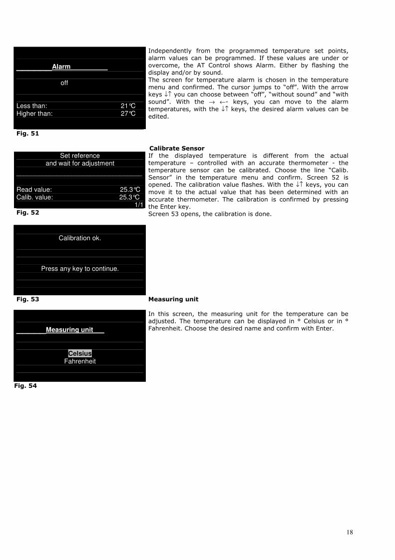
______Alarm__________
off Less than: 21°C Higher than: 27°C
Independently from the programmed temperature set points,
alarm values can be programmed. If these values are under or
overcome, the AT Control shows Alarm. Either by flashing the
display and/or by sound.
The screen for temperature alarm is chosen in the temperature
menu and confirmed. The cursor jumps to “off”. With the arrow keys ↓↑ you can choose between “off”, “without sound” and “with
sound”. With the → ←- keys, you can move to the alarm
temperatures, with the ↓↑ keys, the desired alarm values can be
edited.
Fig. 51
Calibrate Sensor Set reference
and wait for adjustment
__________________________________
Read value: 25.3°C Calib. value: 25.3°C
1/1 Fig. 52
If the displayed temperature is different from the actual
temperature – controlled with an accurate thermometer - the
temperature sensor can be calibrated. Choose the line “Calib.
Sensor” in the temperature menu and confirm. Screen 52 is opened. The calibration value flashes. With the ↓↑ keys, you can
move it to the actual value that has been determined with an
accurate thermometer. The calibration is confirmed by pressing
the Enter key.
Screen 53 opens, the calibration is done.
Calibration ok.
Press any key to continue.
Fig. 53
Measuring unit
_____Measuring unit___
Celsius Fahrenheit
In this screen, the measuring unit for the temperature can be
adjusted. The temperature can be displayed in ° Celsius or in °
Fahrenheit. Choose the desired name and confirm with Enter.
Fig. 54

19
Disconnect temperature sensor
Device disconnected
S02: Temperature
If the temperature sensor is disconnected from the Power Box (or
the cable is damaged), the screen device connected is shown.
Confirm with Enter. The display switches to the basic screen and
a flashing? is shown at the left bottom.
If the temperature sensor is reconnected, the? sign disappears
and the sensor is automatically recognised. If the component
shall be removed from the system completely, choose the
temperature menu - if the sensor is already removed. Choose the
line”disconnect”. Screen 56 appears.
Fig. 55
Disconnect
Temperature Enter: confirm ESC: Cancel
In this screen, the removal of the temperature sensor is
confirmed with Enter – or everything is stopped with ESC. The
temperature sensor is now removed from the system. In the main
menu, the line “Temperature” disappears. If a temperature
sensor is reconnected after some time, it will be automatically be
recognised as new component.
Fig. 56
About
AT Control SW Version: 5.0 Press any key to continue
The last screen of the temperature menu shows the software and
the hardware version installed.
Fig. 57
Level menu
New device connected S02
level
The menu for the level sensor is programmed similar to the
temperature menu. The level sensors can either be connected
directly to the Power Box – using the Audio Jack – or via a T/LV
Interface Box (temperature/level). Anyway, screen 58 will be
shown. Confirm with Enter.
Now, you can choose the line “Level” in the main menu. Confirm
with Enter to program the level sensor.
Fig. 58
_______Level_________
Change Name Programs
Alarm Measuring units
About
“Change Name”. Here, you can change the name (e.g. to “level aquarium 1”). To do this, choose the first line and confirm, “level” is displayed. The first letter flashes. With the arrow keys ↓↑ you
can choose a new letter. With the → ←- keys, you get to the next
letter. If the new name is completed, confirm with Enter.
Fig. 59
20
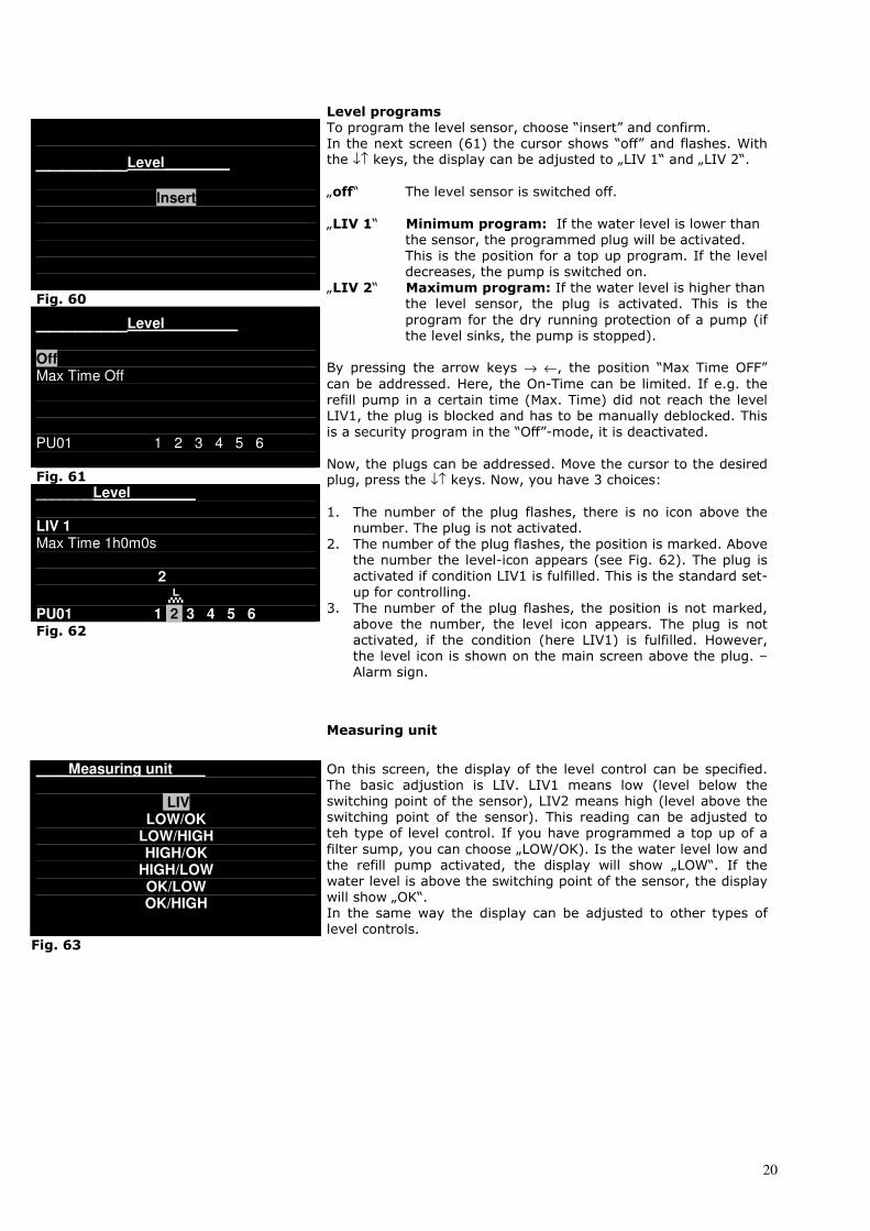
Level programs
_______Level________
Insert
Fig. 60
_______Level_________
Off Max Time Off PU01 1 2 3 4 5 6
Fig. 61 _______Level________
LIV 1 Max Time 1h0m0s 2
PU01 1 2 3 4 5 6 Fig. 62
To program the level sensor, choose “insert” and confirm.
In the next screen (61) the cursor shows “off” and flashes. With the ↓↑ keys, the display can be adjusted to „LIV 1“ and „LIV 2“.
„off“ The level sensor is switched off.
„LIV 1“ Minimum program: If the water level is lower than the sensor, the programmed plug will be activated.
This is the position for a top up program. If the level
decreases, the pump is switched on.
„LIV 2“ Maximum program: If the water level is higher than the level sensor, the plug is activated. This is the
program for the dry running protection of a pump (if
the level sinks, the pump is stopped).
By pressing the arrow keys → ←, the position “Max Time OFF”
can be addressed. Here, the On-Time can be limited. If e.g. the
refill pump in a certain time (Max. Time) did not reach the level
LIV1, the plug is blocked and has to be manually deblocked. This
is a security program in the “Off”-mode, it is deactivated.
Now, the plugs can be addressed. Move the cursor to the desired plug, press the ↓↑ keys. Now, you have 3 choices:
1. The number of the plug flashes, there is no icon above the
number. The plug is not activated.
2. The number of the plug flashes, the position is marked. Above
the number the level-icon appears (see Fig. 62). The plug is
activated if condition LIV1 is fulfilled. This is the standard set-
up for controlling.
3. The number of the plug flashes, the position is not marked,
above the number, the level icon appears. The plug is not
activated, if the condition (here LIV1) is fulfilled. However,
the level icon is shown on the main screen above the plug. –
Alarm sign.
Measuring unit
____Measuring unit____
LIV LOW/OK
LOW/HIGH HIGH/OK
HIGH/LOW OK/LOW OK/HIGH
On this screen, the display of the level control can be specified.
The basic adjustion is LIV. LIV1 means low (level below the
switching point of the sensor), LIV2 means high (level above the
switching point of the sensor). This reading can be adjusted to
teh type of level control. If you have programmed a top up of a
filter sump, you can choose „LOW/OK). Is the water level low and
the refill pump activated, the display will show „LOW“. If the
water level is above the switching point of the sensor, the display
will show „OK“.
In the same way the display can be adjusted to other types of
level controls. Fig. 63
21
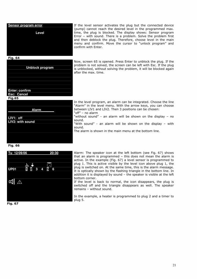
Sensor program error
Level
If the level sensor activates the plug but the connected device
(pump) cannot reach the desired level in the programmed max.
time, the plug is blocked. The display shows: Sensor program
Error – with sound. There is a problem. Solve the problem first
and then deblock the plug. Therefore, choose level in the main
menu and confirm. Move the cursor to “unlock program” and
confirm with Enter.
Fig. 64
Unblock program
Enter: confirm Esc: Cancel
Now, screen 65 is opened. Press Enter to unblock the plug. If the
problem is not solved, the screen can be left with Esc. If the plug
is unblocked, without solving the problem, it will be blocked again
after the max. time.
Fig.65
________Alarm_______
LIV1: off LIV2: with sound
In the level program, an alarm can be integrated. Choose the line
“Alarm” in the level menu. With the arrow keys, you can choose
between LIV1 and LIV2. Then 3 positions can be chosen:
“off” – no alarm
“without sound” - an alarm will be shown on the display – no
sound.
“With sound” - an alarm will be shown on the display – with
sound.
The alarm is shown in the main menu at the bottom line.
Fig. 66
Tu 12/09/06 20:30
UP01 1 2 3 4 5 6
Alarm: The speaker icon at the left bottom (see Fig. 67) shows
that an alarm is programmed – this does not mean the alarm is
active. In the example (Fig. 67) a level sensor is programmed to
plug 1. This is active visible by the level icon above plug 1, the
plug is switched on. At the same time, this is the alarm message.
It is optically shown by the flashing triangle in the bottom line. In
addition it is displayed by sound – the speaker is visible at the left
bottom corner.
If the level is back to normal, the icon disappears, the plug is
switched off and the triangle disappears as well. The speaker
remains – without sound.
In the example, a heater is programmed to plug 2 and a timer to
plug 5.
Fig. 67
22
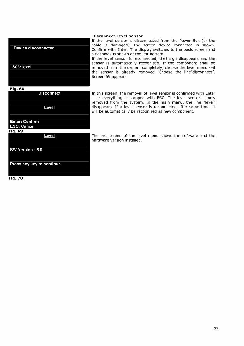
Disconnect Level Sensor
Device disconnected
S03: level
If the level sensor is disconnected from the Power Box (or the
cable is damaged), the screen device connected is shown.
Confirm with Enter. The display switches to the basic screen and
a flashing? is shown at the left bottom.
If the level sensor is reconnected, the? sign disappears and the
sensor is automatically recognised. If the component shall be
removed from the system completely, choose the level menu -–if
the sensor is already removed. Choose the line”disconnect”.
Screen 69 appears.
Fig. 68
Disconnect
Level Enter: Confirm ESC: Cancel
In this screen, the removal of level sensor is confirmed with Enter
– or everything is stopped with ESC. The level sensor is now
removed from the system. In the main menu, the line “level”
disappears. If a level sensor is reconnected after some time, it
will be automatically be recognized as new component.
Fig. 69 Level
SW Version : 5.0 Press any key to continue
The last screen of the level menu shows the software and the
hardware version installed.
Fig. 70
23
pH control with AT Control
With the connection of a pH Interface Box and a pH electrode, the AT control can be supplied with a pH control.
If both is connected to the Power Box, the pH control is automatically recognised. Like the temperature control,
the pH control offer many varieties. The main purpose is the connection of a solenoid valve to control the pH
value with CO2.
pH Menu
________pH________
Change Name
Programs Data Record
Alarm Calibrate Sensor Measuring units
About Fig. 71
To get to the pH Menu, choose “pH” in the main menu. In this
menu, you can program a pH control – if you have connected a
pH Interface and a pH electrode. Screen 71 opens. With the arrow
keys, you can address the desired line and confirm.
“Change Name”. Here, you can change the name (e.g. to “pH aquarium 1”). To do this, choose the first line and confirm. “pH”
is displayed. The first letter flashes. With the arrow keys ↓↑ you
can choose a new letter. With the → ←- keys, you get to the next
letter. If the new name is completed, confirm with Enter.
pH Programs
________pH_______
insert
Fig. 72
______Programs________
ref. pH 6,8
∆ MIN: ∆Max: 0,05 0,05 plugs confirm Fig. 73
2 pH UP01 1 2 3 4 5 6 pH UP01 1 2 3 4 5 6
Programs: Choose in the upper screen “programs” and screen 44 opens. Choose “Insert” to insert a program. If programs
already exist, a second line “show/modify/delete” is displayed.
Choose this line to edit an existing pH program.
Insert a set point for pH: If you choose “Insert, screen 73 opens, the line “Ref.” is flashing.
Here, you can edit the desired value for the set point. The actual
pH value is displayed in °C. With Enter, you come to the
reference value. You can change the value to the desired point with the arrow keys ↓↑. Confirm with Enter.
Now, the line ∆ min. flashes. With the arrow keys ↓↑ , you can
add a value for the minimum deviation, e. g. 0.2. If the actual pH
value decreases below the set point for 0.2, the plug is switched
on. With the → ←- keys, you get to the ∆ Max value. If you have
these 2 values (the hysteresis), confirm with Enter. Now, you can
program the plugs (see screen 46).
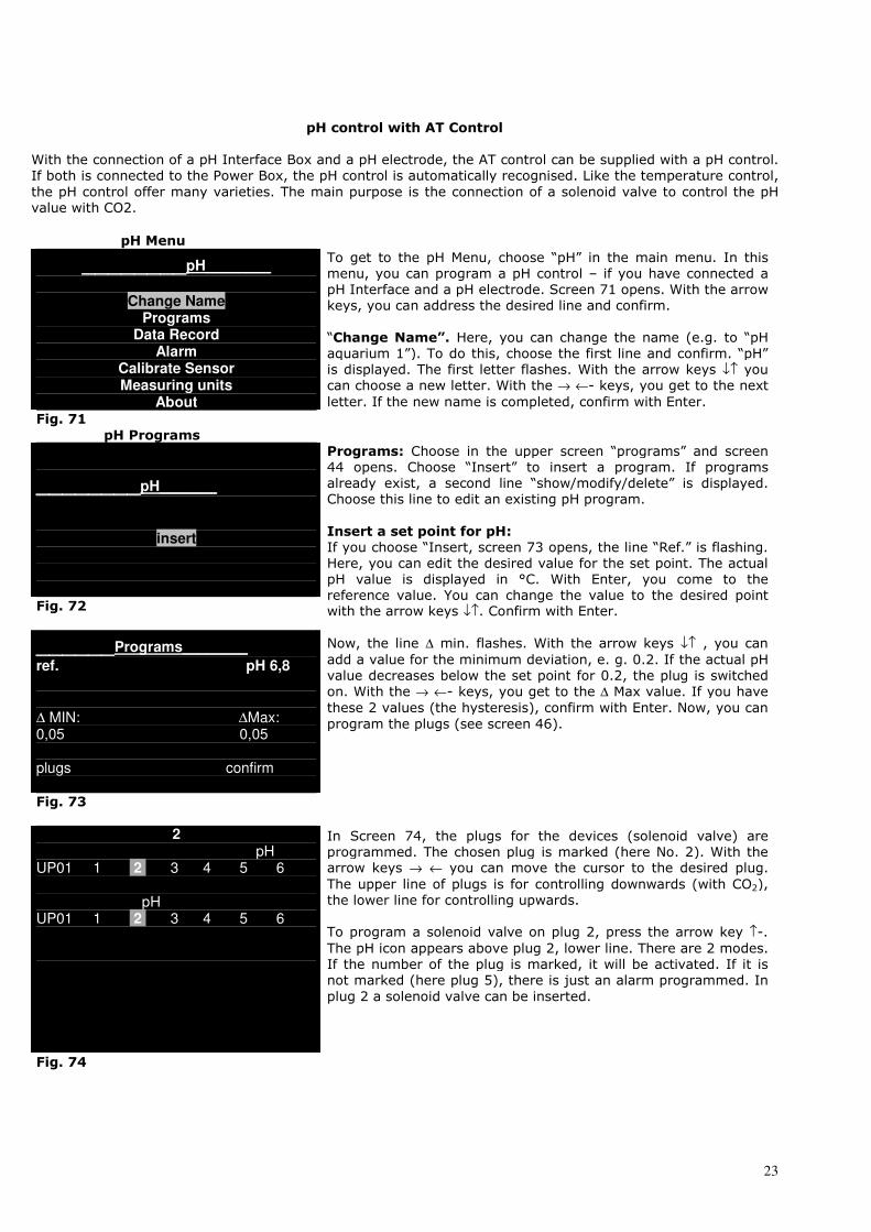
In Screen 74, the plugs for the devices (solenoid valve) are
programmed. The chosen plug is marked (here No. 2). With the arrow keys → ← you can move the cursor to the desired plug.
The upper line of plugs is for controlling downwards (with CO2),
the lower line for controlling upwards.
To program a solenoid valve on plug 2, press the arrow key ↑-.
The pH icon appears above plug 2, lower line. There are 2 modes.
If the number of the plug is marked, it will be activated. If it is
not marked (here plug 5), there is just an alarm programmed. In
plug 2 a solenoid valve can be inserted.
Fig. 74
24
______Programs________
curve
∆ MIN: ∆Max: 0,05 0,05 plugs confirm
pH-in the day-night cycle –
If the pH value shall not be hold constant, a pH curve can be
programmed. For the programming, see temperature menu
(Fig. 46 – 48).
Fig. 75 Data Record
∆
Current Date 11/08 10:00 6,55
Choose the line “Data Record” in the pH menu. The curve appears
with the saved data (see Fig. 7 and 47).
Fig. 76
______Alarm__________
off Less than: pH 7.8 Greater than: pH 8.4
Independently from the programmed pH set points, alarm values
can be programmed. If these values are under or overcome, the
AT Control shows alarm. Either by flashing the display and/or by
sound.
The screen for pH- alarm is chosen in the pH-menu and confirmed. The cursor jumps to “off”. With the arrow keys ↓↑ you
can choose between “off”, “without sound” and “with sound”.
With the → ←- keys, you can move to the alarm values, with the
↓↑ keys, the desired alarm values can be edited.
Fig. 77
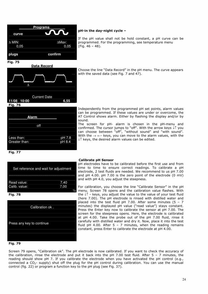
Calibrate pH Sensor
Set reference and wait for adjustment
__________________________________
Read value: 7,40 Calib. value: 7,00
½ Fig. 78
Calibration ok .
Press any key to continue
Fig. 79
pH electrodes have to be calibrated before the first use and from
time to time to ensure correct readings. To calibrate a pH
electrode, 2 test fluids are needed. We recommend to us pH 7.00
and pH 4.00. pH 7.00 is the zero point of the electrode (0 mV)
and with pH 4.0, you adjust the steepness.
For calibration, you choose the line “Calibrate Sensor” in the pH
menu. Screen 78 opens and the calibration value flashes. With the ↓↑ - keys, you adjust the value to the value of your test fluid
(here 7.00). The pH electrode is rinsed with distilled water and
placed into the test fluid pH 7.00. After some minutes (5 – 7
minutes) the displayed pH value (“read value”) stays constant.
Press the Enter key now to calibrate the sensor at pH 7.00. The
screen for the steepness opens. Here, the electrode is calibrated
at pH 4.00. Take the probe out of the pH 7.00 fluid, rinse it
carefully with distilled water and dry it. Now, place it into the test
fluid pH 4.00. After 5 – 7 minutes, when the reading remains
constant, press Enter to calibrate the electrode at pH 4.00.
Screen 79 opens, “Calibration ok”. The pH electrode is now calibrated. If you want to check the accuracy of
the calibration, rinse the electrode and put it back into the pH 7.00 test fluid. After 5 – 7 minutes, the
reading should show pH 7. If you calibrate the electrode when you have activated the pH control (e.g.,
connected a CO2- supply) shut off the plug for the pH control during calibration. You can use the manual
control (fig. 22) or program a function key to the pH plug (see Fig. 37).
25
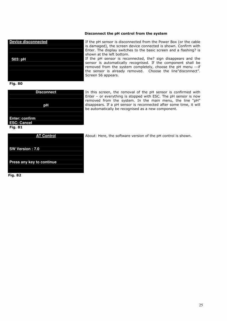
Disconnect the pH control from the system
Device disconnected
S03: pH
If the pH sensor is disconnected from the Power Box (or the cable
is damaged), the screen device connected is shown. Confirm with
Enter. The display switches to the basic screen and a flashing? is
shown at the left bottom.
If the pH sensor is reconnected, the? sign disappears and the
sensor is automatically recognised. If the component shall be
removed from the system completely, choose the pH menu -–if
the sensor is already removed. Choose the line”disconnect”.
Screen 56 appears.
Fig. 80
Disconnect
pH Enter: confirm ESC: Cancel
In this screen, the removal of the pH sensor is confirmed with
Enter – or everything is stopped with ESC. The pH sensor is now
removed from the system. In the main menu, the line “pH”
disappears. If a pH sensor is reconnected after some time, it will
be automatically be recognised as a new component.
Fig. 81
AT Control
SW Version : 7.0 Press any key to continue
About: Here, the software version of the pH control is shown.
Fig. 82
26
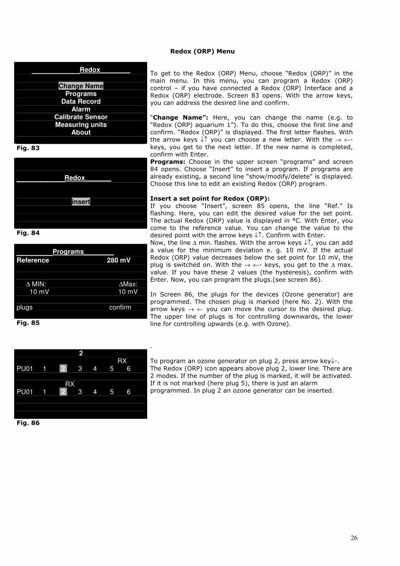
Redox (ORP) Menu
________Redox________
Change Name
Programs Data Record
Alarm Calibrate Sensor Measuring units
About
Fig. 83
To get to the Redox (ORP) Menu, choose “Redox (ORP)” in the
main menu. In this menu, you can program a Redox (ORP)
control – if you have connected a Redox (ORP) Interface and a
Redox (ORP) electrode. Screen 83 opens. With the arrow keys,
you can address the desired line and confirm.
“Change Name”: Here, you can change the name (e.g. to “Redox (ORP) aquarium 1”). To do this, choose the first line and
confirm. “Redox (ORP)” is displayed. The first letter flashes. With
the arrow keys ↓↑ you can choose a new letter. With the → ←-
keys, you get to the next letter. If the new name is completed,
confirm with Enter.
________Redox_______
insert
Fig. 84
______Programs________
Reference 280 mV
∆ MIN: ∆Max: 10 mV 10 mV plugs confirm Fig. 85
Programs: Choose in the upper screen “programs” and screen 84 opens. Choose “Insert” to insert a program. If programs are
already existing, a second line “show/modify/delete” is displayed.
Choose this line to edit an existing Redox (ORP) program.
Insert a set point for Redox (ORP): If you choose “Insert”, screen 85 opens, the line “Ref.” Is
flashing. Here, you can edit the desired value for the set point.
The actual Redox (ORP) value is displayed in °C. With Enter, you
come to the reference value. You can change the value to the desired point with the arrow keys ↓↑. Confirm with Enter.
Now, the line ∆ min. flashes. With the arrow keys ↓↑, you can add
a value for the minimum deviation e. g. 10 mV. If the actual
Redox (ORP) value decreases below the set point for 10 mV, the plug is switched on. With the → ←- keys, you get to the ∆ max.
value. If you have these 2 values (the hysteresis), confirm with
Enter. Now, you can program the plugs.(see screen 86).
In Screen 86, the plugs for the devices (Ozone generator) are
programmed. The chosen plug is marked (here No. 2). With the arrow keys → ← you can move the cursor to the desired plug.
The upper line of plugs is for controlling downwards, the lower
line for controlling upwards (e.g. with Ozone).
.
2 RX PU01 1 2 3 4 5 6 RX PU01 1 2 3 4 5 6
Fig. 86
To program an ozone generator on plug 2, press arrow key↓-.
The Redox (ORP) icon appears above plug 2, lower line. There are
2 modes. If the number of the plug is marked, it will be activated.
If it is not marked (here plug 5), there is just an alarm
programmed. In plug 2 an ozone generator can be inserted.

27
______Programs_______
curve
∆ MIN: ∆Max: 0mV 0 mV plugs confirm
Redox in the day - night cycle
If the Redox value shall not be held constant, a Redox curve can
be programmed. For the programming, see the temperature
menu (Fig. 46 – 48).
Fig. 87
Data Record
∆
current data 11/08 10:00 250 mV
Choose the line “Data Record” in the pH menu The curve appears
with the saved data. See Fig. 88.
Fig. 88
______Alarm
off less than: 200 mV greater than: 500 mV
Independently from the programmed Redox set points, alarm
values can be programmed. If these values are under or
overcome, the AT Control shows Alarm. Either by flashing the
display and/or by sound.
The screen for Redox- alarm is chosen in the Redox-menu and
confirmed. The cursor jumps to “off”. With the arrow keys ↓↑ you
can choose between “off”, “without sound” and “with sound”. With the → ←- keys, you can move to the alarm values, with the
↓↑ keys, the desired alarm values can be edited.
Fig. 89
Calibrate Redox Sensor
Set Reference and wait for adjustment
__________________________________
read value: 260 mV calibration value: 230 mV
1/1 Fig. 90
Redox electrodes should be calibrated before the first use and
from time to time to ensure correct readings. To calibrate a
Redox electrode, a test fluid is needed. The Redox electrode is
rinsed with distilled water and placed into the test fluid e. g. 230
mV. After some minutes (5 – 7 minutes) the displayed Redox
value (“read value”) stays constant. Press the Enter key now to
calibrate the sensor at 230 mV. Screen 91 opens – the calibration
is ok.
Calibration ok.
Press any key to continue
Fig. 91
28
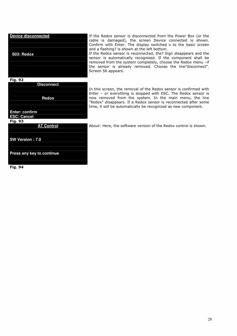
Device disconnected
S03: Redox
If the Redox sensor is disconnected from the Power Box (or the
cable is damaged), the screen Device connected is shown.
Confirm with Enter. The display switched s to the basic screen
and a flashing? is shown at the left bottom.
If the Redox sensor is reconnected, the? Sign disappears and the
sensor is automatically recognised. If the component shall be
removed from the system completely, choose the Redox menu –if
the sensor is already removed. Choose the line”disconnect”.
Screen 56 appears.
Fig. 92
Disconnect
Redox Enter: confirm ESC: Cancel
In this screen, the removal of the Redox sensor is confirmed with
Enter – or everything is stopped with ESC. The Redox sensor is
now removed from the system. In the main menu, the line
“Redox” disappears. If a Redox sensor is reconnected after some
time, it will be automatically be recognized as new component.
Fig. 93 AT Control
SW Version : 7.0 Press any key to continue
About: Here, the software version of the Redox control is shown.
Fig. 94
29
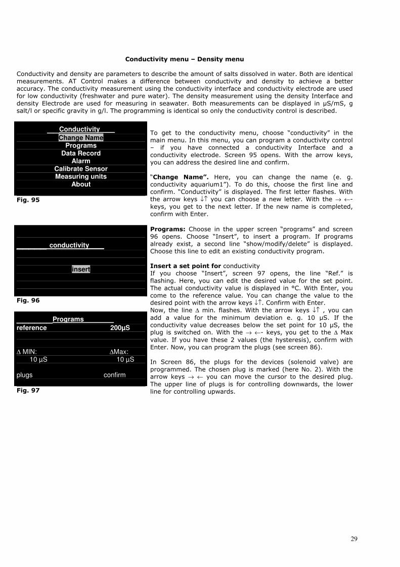
Conductivity menu – Density menu
Conductivity and density are parameters to describe the amount of salts dissolved in water. Both are identical
measurements. AT Control makes a difference between conductivity and density to achieve a better
accuracy. The conductivity measurement using the conductivity interface and conductivity electrode are used
for low conductivity (freshwater and pure water). The density measurement using the density Interface and
density Electrode are used for measuring in seawater. Both measurements can be displayed in µS/mS, g
salt/l or specific gravity in g/l. The programming is identical so only the conductivity control is described.
__Conductivity____
Change Name Programs
Data Record Alarm
Calibrate Sensor Measuring units
About
Fig. 95
To get to the conductivity menu, choose “conductivity” in the
main menu. In this menu, you can program a conductivity control
– if you have connected a conductivity Interface and a
conductivity electrode. Screen 95 opens. With the arrow keys,
you can address the desired line and confirm.
“Change Name”. Here, you can change the name (e. g. conductivity aquarium1”). To do this, choose the first line and
confirm. “Conductivity” is displayed. The first letter flashes. With
the arrow keys ↓↑ you can choose a new letter. With the → ←-
keys, you get to the next letter. If the new name is completed,
confirm with Enter.
_____ conductivity____
insert
Fig. 96
______Programs________
reference 200µS
∆ MIN: ∆Max: 10 µS 10 µS plugs confirm Fig. 97
Programs: Choose in the upper screen “programs” and screen 96 opens. Choose “Insert”, to insert a program. If programs
already exist, a second line “show/modify/delete” is displayed.
Choose this line to edit an existing conductivity program.
Insert a set point for conductivity If you choose “Insert”, screen 97 opens, the line “Ref.” is
flashing. Here, you can edit the desired value for the set point.
The actual conductivity value is displayed in °C. With Enter, you
come to the reference value. You can change the value to the desired point with the arrow keys ↓↑. Confirm with Enter.
Now, the line ∆ min. flashes. With the arrow keys ↓↑ , you can
add a value for the minimum deviation e. g. 10 µS. If the
conductivity value decreases below the set point for 10 µS, the plug is switched on. With the → ←- keys, you get to the ∆ Max
value. If you have these 2 values (the hysteresis), confirm with
Enter. Now, you can program the plugs (see screen 86).
In Screen 86, the plugs for the devices (solenoid valve) are
programmed. The chosen plug is marked (here No. 2). With the arrow keys → ← you can move the cursor to the desired plug.
The upper line of plugs is for controlling downwards, the lower
line for controlling upwards.

30
2 µS PU01 1 2 3 4 5 6 µS PU01 1 2 3 4 5 6
Fig. 98
In Screen 98, the plugs for the devices are programmed. The chosen plug is marked (here No. 2). With the arrow keys → ←
you can move the cursor to the desired plug. The upper line of
plugs is for controlling downwards, the lower line for controlling
upwards.
To program a reverse osmosis unit on plug 2, press the arrow key
↓-. The conductivity icon appears above plug 2, lower line. There
are 2 modes. If the number of the plug is marked, it will be
activated. If it is not marked (here plug 5), there is just an alarm
programmed.
______Programs_______
curve
∆ MIN: ∆Max: 0µS 0µSV plugs confirm
Conductivity in the day - night cycle If the conductivity value shall not be held constant, a conductivity
curve can be programmed. For the programming, see the
temperature menu (Fig. 46 – 48).
Fig. 99
Data Record
∆
current date 11/08 10:00 250 µS
Choose the line “Data Record” in the conductivity menu. The
curve appears with the saved data. See Fig. 100.
Fig. 100
______Alarm_______
off Less than: 200 µS Greater than: 500 µS
Independently from the programmed conductivity set points,
alarm values can be programmed. If these values are under or
overcome the AT Control shows alarm either by flashing the
display and/or by sound.
The screen for conductivity-alarm is chosen in the conductivity -
menu and confirmed. The cursor jumps to “off”. With the arrow keys ↓↑ you can choose between “off”, “without sound” and “with
sound”. With the → ←- keys, you can move to the alarm values,
with the ↓↑ keys, the desired alarm values can be edited.
Fig. 101
Calibrate Conductivity Sensor
Set reference and wait for adjustment
__________________________________
Read value: 260 µS Calibration value: 230 µS
1/1 Fig. 102
Conductivity electrodes should be calibrated before the first use
and from time to time to ensure correct readings. To calibrate a
conductivity electrode, a test fluid is needed. The conductivity
electrode is rinsed with distilled water and placed into the test
fluid, e. g. 250 µS. After some minutes (5 – 7 minutes) the
displayed conductivity value (“read value”) stays constant. Press
the Enter key now to calibrate the sensor at 250µ. Screen 103
opens – the calibration is ok.
31
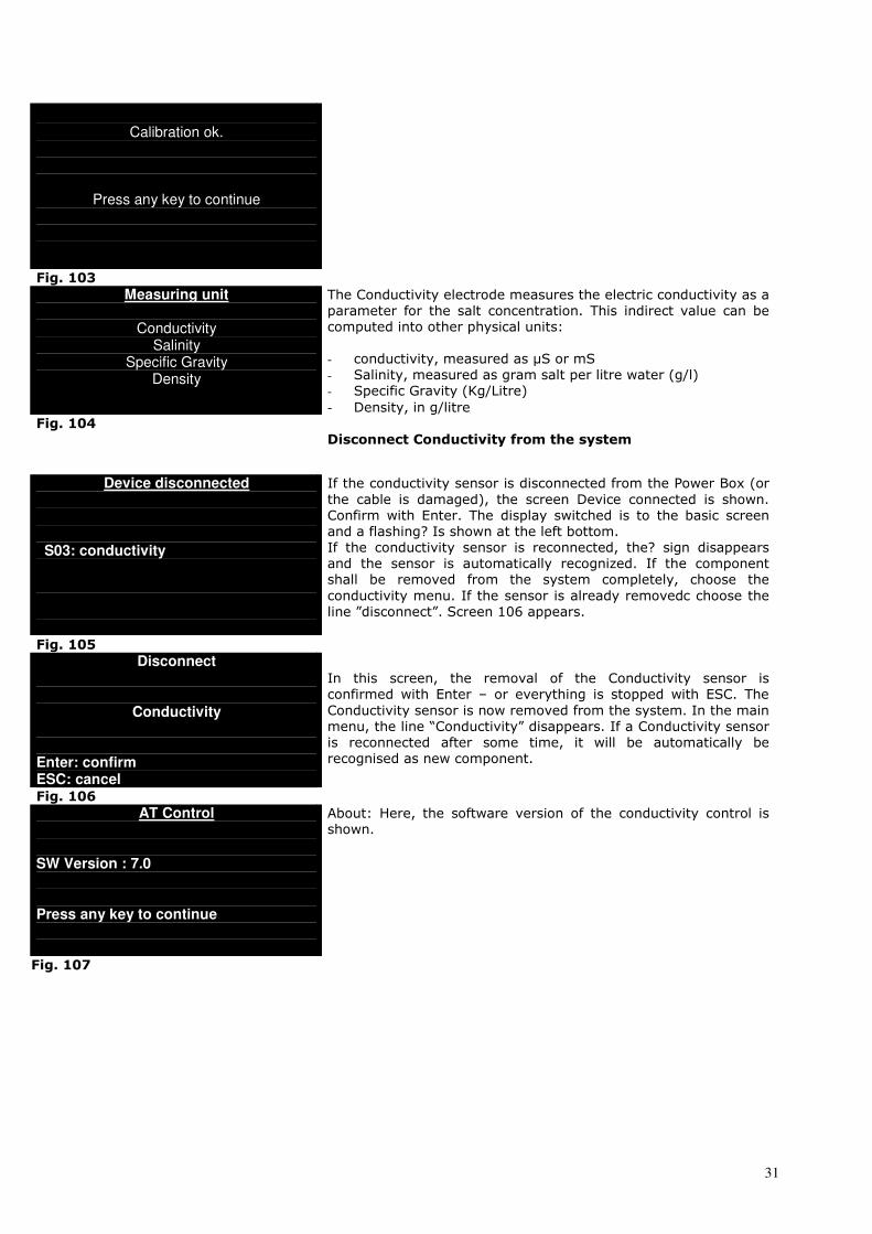
Calibration ok.
Press any key to continue
Fig. 103 Measuring unit
Conductivity
Salinity Specific Gravity
Density
The Conductivity electrode measures the electric conductivity as a
parameter for the salt concentration. This indirect value can be
computed into other physical units:
- conductivity, measured as µS or mS
- Salinity, measured as gram salt per litre water (g/l)
- Specific Gravity (Kg/Litre)
- Density, in g/litre Fig. 104
Disconnect Conductivity from the system
Device disconnected
S03: conductivity
If the conductivity sensor is disconnected from the Power Box (or
the cable is damaged), the screen Device connected is shown.
Confirm with Enter. The display switched is to the basic screen
and a flashing? Is shown at the left bottom.
If the conductivity sensor is reconnected, the? sign disappears
and the sensor is automatically recognized. If the component
shall be removed from the system completely, choose the
conductivity menu. If the sensor is already removedc choose the
line ”disconnect”. Screen 106 appears.
Fig. 105
Disconnect
Conductivity Enter: confirm ESC: cancel
In this screen, the removal of the Conductivity sensor is
confirmed with Enter – or everything is stopped with ESC. The
Conductivity sensor is now removed from the system. In the main
menu, the line “Conductivity” disappears. If a Conductivity sensor
is reconnected after some time, it will be automatically be
recognised as new component.
Fig. 106 AT Control
SW Version : 7.0 Press any key to continue
About: Here, the software version of the conductivity control is
shown.
Fig. 107

32
Ethernet Module
The Ethernet module allows to connect the AT control to the Internet to control the aquarium and
read the measuring values online.
Contents
• Information • Safety advice • Contents • Minimum requirements of the system • Connection of the Ethernet module to a local LAN-Net • Connection of the Ethernet module through the Internet • Main menu Menu parameter Menu address Menu mail on/off Menu alarms Menu info • Display of the Homepage • Homepage • Problem shooting • Warranty 3 - 17 IsACQ225C-0 DEURev.270607-0 Please read these instructions carefully before using the Ethernet module.
Technical data Ethernet module: Voltage: 12 V/DC
Current: 150 mA
Dimensions: 105 (l) x 80 (w) x 35 (h) mm
Sich
- Use the module only for the purpose it has been designed for. Every other application that is not
listed in the manual may irreversibly damage the module.
- Do not try to dismantle the unit. It contains no parts that can be repaired by the user. Any repairs
may only be done by authorized workshops and personal. No warranty will be taken for any
damages for persons or goods caused by opening the unit.
- Use only original accessories from Aqua Medic to connect it to the module. The connection of not
original accessories may result in damages like fire, electrical hazards or even injuries of people.
Keep the module out of reach of children. The warranty is excluded if the damage is caused by
misuse of the module.
- The module is not water tight. It may not have direct contact to any liquids. For indoor use only.
Do not use inflammable liquids for cleaning,when they may contact electrical parts.
33
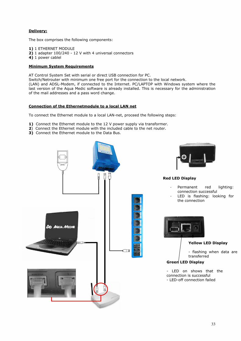
Delivery: The box comprises the following components:
1) 1 ETHERNET MODULE 2) 1 adapter 100/240 - 12 V with 4 universal connectors 4) 1 power cablel Inhalt de Minimum System Requirements AT Control System Set with serial or direct USB connection for PC.
Switch/Netrouter with minimum one free port for the connection to the local network.
(LAN) and ADSL-Modem, if connected to the Internet. PC/LAPTOP with Windows system where the
last version of the Aqua Medic software is already installed. This is necessary for the administration
of the mail addresses and a pass word change.
Connection of the Ethernetmodule to a local LAN net
To connect the Ethernet module to a local LAN-net, proceed the following steps:
1) Connect the Ethernet module to the 12 V power supply via transformer. 2) Connect the Ethernet module with the included cable to the net router. 3) Connect the Ethernet module to the Data Bus.
Red LED Display
- Permanent red lighting:
connection successful
- LED is flashing: looking for
the connection
Yellow LED Display - flashing when data are
transferred
Green LED Display - LED on shows that the
connection is successful
- LED-off connection failed
34
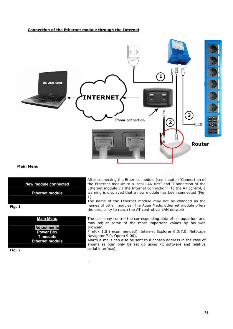
Connection of the Ethernet module through the Internet
Main Menu
New module connected
Ethernet module
Fig. 1
After connecting the Ethernet module (see chapter:“Connection of
the Ethernet module to a local LAN Net” and “Connection of the
Ethernet module via the Internet connection”) to the AT control, a
warning is displayed that a new module has been connected (Fig.
1).
The name of the Ethernet module may not be changed as the
names of other modules. The Aqua Medic Ethernet module offers
the possibility to reach the AT control via LAN network.
Main Menu
Adjustments Power Box Time/date
Ethernet module Fig. 2
The user may control the corresponding data of his aquarium and
may adjust some of the most important values by his web
browser.
Firefox 1.5 (recommended), Internet Explorer 6.0/7.0, Netscape
Navigator 7.0, Opera 9.00).
Alarm e-mails can also be sent to a chosen address in the case of
anomalies (can only be set up using PC software and relative
serial interface).
.
Phone connection
35
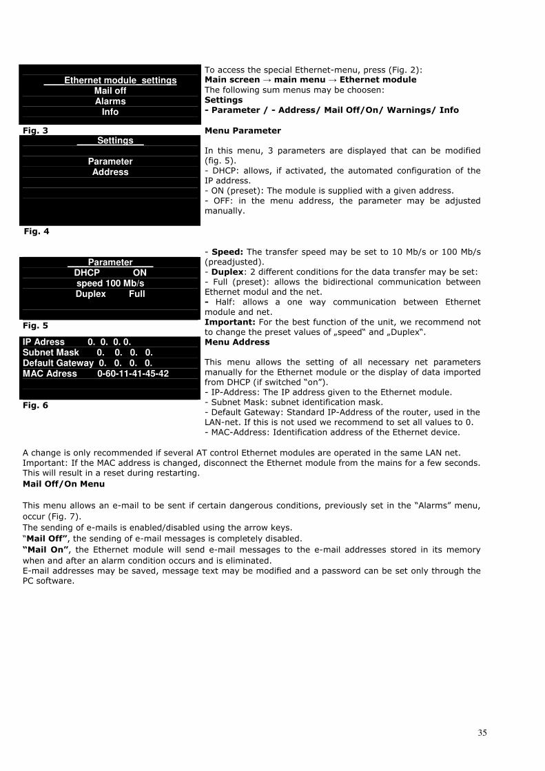
____Ethernet module_settings
Mail off Alarms
Info
To access the special Ethernet-menu, press (Fig. 2): Main screen → main menu → Ethernet module The following sum menus may be choosen:
Settings - Parameter / - Address/ Mail Off/On/ Warnings/ Info
Fig. 3 ____Settings__
Parameter Address
Menu Parameter In this menu, 3 parameters are displayed that can be modified
(fig. 5).
- DHCP: allows, if activated, the automated configuration of the
IP address.
- ON (preset): The module is supplied with a given address.
- OFF: in the menu address, the parameter may be adjusted
manually.
Fig. 4
____Parameter____
DHCP ON speed 100 Mb/s Duplex Full
Fig. 5
- Speed: The transfer speed may be set to 10 Mb/s or 100 Mb/s (preadjusted).
- Duplex: 2 different conditions for the data transfer may be set: - Full (preset): allows the bidirectional communication between
Ethernet modul and the net.
- Half: allows a one way communication between Ethernet module and net.
Important: For the best function of the unit, we recommend not to change the preset values of „speed“ and „Duplex“.
IP Adress 0. 0. 0. 0. Subnet Mask 0. 0. 0. 0. Default Gateway 0. 0. 0. 0. MAC Adress 0-60-11-41-45-42 Fig. 6
Menu Address This menu allows the setting of all necessary net parameters
manually for the Ethernet module or the display of data imported
from DHCP (if switched “on”).
- IP-Address: The IP address given to the Ethernet module.
- Subnet Mask: subnet identification mask.
- Default Gateway: Standard IP-Address of the router, used in the
LAN-net. If this is not used we recommend to set all values to 0.
- MAC-Address: Identification address of the Ethernet device.
A change is only recommended if several AT control Ethernet modules are operated in the same LAN net.
Important: If the MAC address is changed, disconnect the Ethernet module from the mains for a few seconds.
This will result in a reset during restarting.
Mail Off/On Menu
This menu allows an e-mail to be sent if certain dangerous conditions, previously set in the “Alarms” menu,
occur (Fig. 7).
The sending of e-mails is enabled/disabled using the arrow keys.
“Mail Off”, the sending of e-mail messages is completely disabled. “Mail On”, the Ethernet module will send e-mail messages to the e-mail addresses stored in its memory when and after an alarm condition occurs and is eliminated.
E-mail addresses may be saved, message text may be modified and a password can be set only through the
PC software.
36
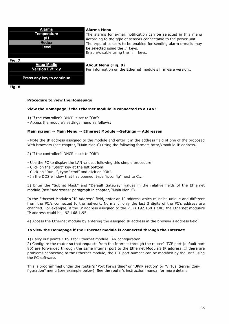
Alarms Temperature
pH Redox Level
Alarms Menu The alarms for e-mail notification can be selected in this menu
according to the type of sensors connectable to the power unit.
The type of sensors to be enabled for sending alarm e-mails may
be selected using the ↓↑ keys.
Enable/disable using the →← keys.
Fig. 7 Aqua Medic
Version FW: x.y
Press any key to continue
About Menu (Fig. 8) For information on the Ethernet module’s firmware version..
Fig. 8 - 17 IsACQ225C-0 DEU Rev. 270607-0 Procedure to view the Homepage View the Homepage if the Ethernet module is connected to a LAN:
1) If the controller’s DHCP is set to “On”: - Access the module’s settings menu as follows:
Main screen → Main Menu → Ethernet Module →Settings → Addresses
- Note the IP address assigned to the module and enter it in the address field of one of the proposed
Web browsers (see chapter, “Main Menu”) using the following format: http://module IP address.
2) If the controller’s DHCP is set to “Off”:
- Use the PC to display the LAN values, following this simple procedure:
- Click on the “Start” key at the left bottom.
- Click on “Run…”, type “cmd” and click on “OK”.
- In the DOS window that has opened, type “ipconfig” next to C...
3) Enter the “Subnet Mask” and “Default Gateway” values in the relative fields of the Ethernet module (see “Addresses” paragraph in chapter, “Main Menu”).
In the Ethernet Module’s “IP Address” field, enter an IP address which must be unique and different
from the PC/s connected to the network. Normally, only the last 3 digits of the PC’s address are
changed. For example, if the IP address assigned to the PC is 192.168.1.100, the Ethernet module’s
IP address could be 192.168.1.95.
4) Access the Ethernet module by entering the assigned IP address in the browser’s address field.
To view the Homepage if the Ethernet module is connected through the Internet:
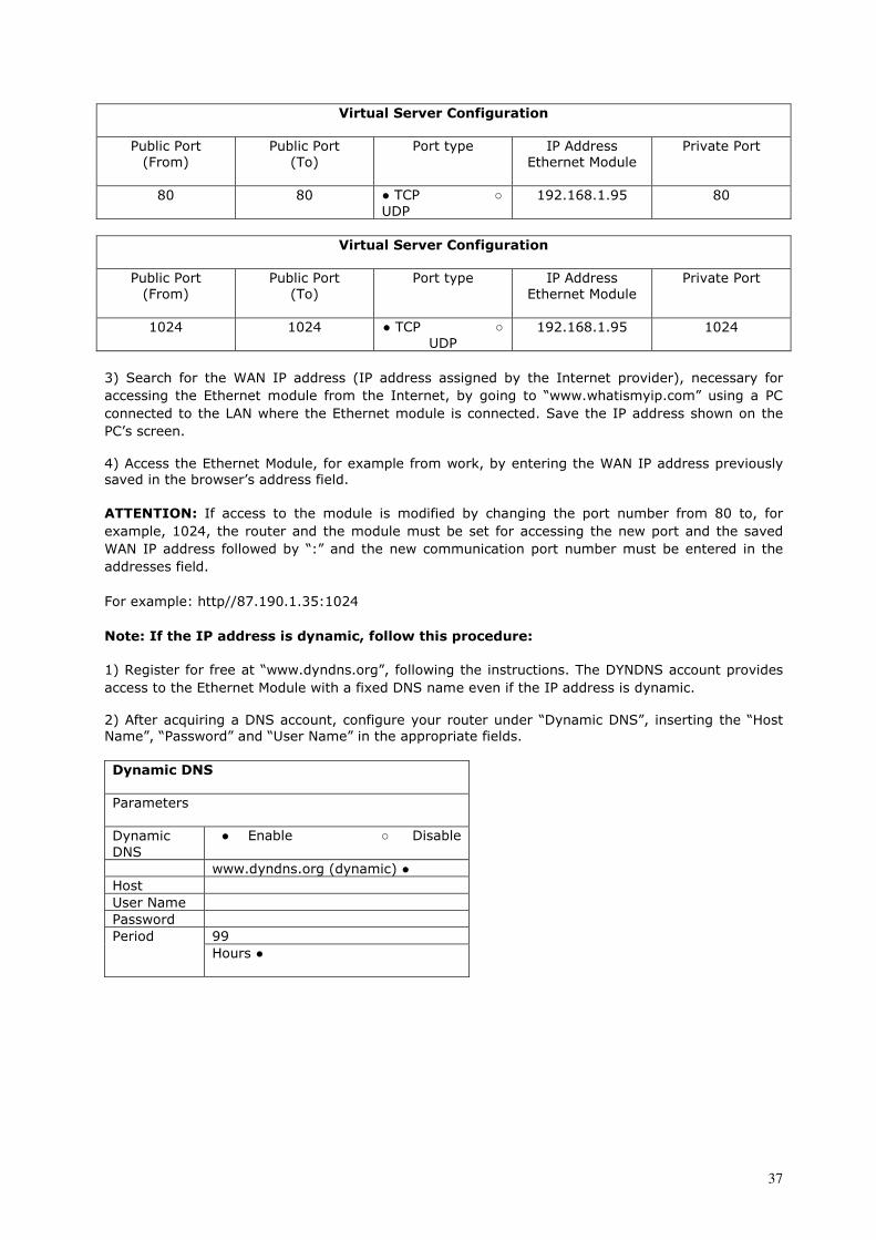
1) Carry out points 1 to 3 for Ethernet module LAN configuration. 2) Configure the router so that requests from the Internet through the router’s TCP port (default port 80) are forwarded through the same internal port to the Ethernet Module’s IP address. If there are
problems connecting to the Ethernet module, the TCP port number can be modified by the user using
the PC software.
This is programmed under the router’s “Port Forwarding” or “UPnP section” or “Virtual Server Con-
figuration” menu (see example below). See the router’s instruction manual for more details.
37
Virtual Server Configuration
Public Port
(From)
Public Port
(To)
Port type
IP Address
Ethernet Module
Private Port
80 80 ● TCP ○
UDP
192.168.1.95 80
Virtual Server Configuration
Public Port
(From)
Public Port
(To)
Port type IP Address
Ethernet Module
Private Port
1024 1024 ● TCP ○
UDP
192.168.1.95 1024
3) Search for the WAN IP address (IP address assigned by the Internet provider), necessary for accessing the Ethernet module from the Internet, by going to “www.whatismyip.com” using a PC
connected to the LAN where the Ethernet module is connected. Save the IP address shown on the
PC’s screen.
4) Access the Ethernet Module, for example from work, by entering the WAN IP address previously saved in the browser’s address field.
Anzeige der Homepage10 - 17 IsACQ225C-0DEU Rev. 270607-0 ATTENTION: If access to the module is modified by changing the port number from 80 to, for example, 1024, the router and the module must be set for accessing the new port and the saved
WAN IP address followed by “:” and the new communication port number must be entered in the
addresses field.
For example: http//87.190.1.35:1024
Note: If the IP address is dynamic, follow this procedure:
1) Register for free at “www.dyndns.org”, following the instructions. The DYNDNS account provides access to the Ethernet Module with a fixed DNS name even if the IP address is dynamic.
2) After acquiring a DNS account, configure your router under “Dynamic DNS”, inserting the “Host Name”, “Password” and “User Name” in the appropriate fields.
Dynamic DNS Parameters
Dynamic
DNS ● Enable ○ Disable
www.dyndns.org (dynamic) ●
Host
User Name
Password
99 Period
Hours ●
Anzeige der Homepage 11 –
38
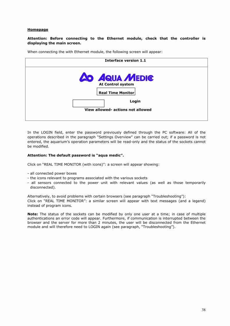
Homepage Attention: Before connecting to the Ethernet module, check that the controller is displaying the main screen.
When connecting the with Ethernet module, the following screen will appear:
Ethernet Interface version 1.1
At Control system
Real Time Monitor
Login View allowed- actions not allowed
In the LOGIN field, enter the password previously defined through the PC software: All of the
operations described in the paragraph “Settings Overview” can be carried out; if a password is not
entered, the aquarium’s operation parameters will be read-only and the status of the sockets cannot
be modified.
Attention: The default password is “aqua medic”.
Click on “REAL TIME MONITOR (with icons)”: a screen will appear showing:
- all connected power boxes
- the icons relevant to programs associated with the various sockets
- all sensors connected to the power unit with relevant values (as well as those temporarily
disconnected).
Alternatively, to avoid problems with certain browsers (see paragraph “Troubleshooting”):
Click on “REAL TIME MONITOR”: a similar screen will appear with text messages (and a legend)
instead of program icons.
Note: The status of the sockets can be modified by only one user at a time; in case of multiple authentications an error code will appear. Furthermore, if communication is interrupted between the
browser and the server for more than 2 minutes, the user will be disconnected from the Ethernet
module and will therefore need to LOGIN again (see paragraph, “Troubleshooting”). Überblick über die Einstellungen
39
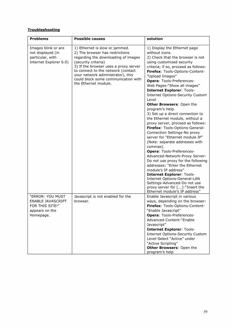
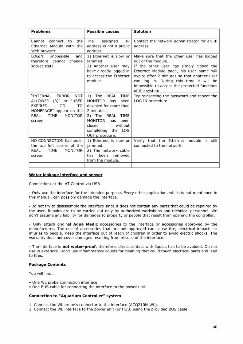
Troubleshooting
Problems Possible causes solution
Images blink or are
not displayed (in
particular, with
Internet Explorer 6.0)
1) Ethernet is slow or jammed.
2) The browser has restrictions
regarding the downloading of images
(security criteria)
3) If the browser uses a proxy server
to connect to the network (contact
your network administrator), this
could block some communication with
the Ethernet module.
1) Display the Ethernet page
without icons.
2) Check that the browser is not
using customized security
criteria; if so, proceed as follows:
Firefox: Tools-Options-Content-”Upload Images”
Opera: Tools-Preferences- Web Pages-“Show all images”
Internet Explorer: Tools-Internet Options-Security Custom
Level
Other Browsers: Open the program’s Help.
3) Set up a direct connection to
the Ethernet module, without a
proxy server, proceed as follows:
Firefox: Tools-Options-General-Connection Settings-No proxy
server for “Ethernet module IP”
(Note: separate addresses with
commas).
Opera: Tools-Preferences-Advanced-Network-Proxy Server-
Do not use proxy for the following
addresses: “Enter the Ethernet
module’s IP address”
Internet Explorer: Tools-Internet Options-General-LAN
Settings-Advanced-Do not use
proxy server for [...]-“Insert the
Ethernet module’s IP address”
“ERROR: YOU MUST
ENABLE JAVASCRIPT
FOR THIS SITE!”
appears on the
Homepage.
Javascript is not enabled for the
browser.
Enable Javascript in various
ways, depending on the browser:
Firefox: Tools-Options-Content-“Enable Javascript”
Opera: Tools-Preferences-Advanced-Content-“Enable
Javascript”
Internet Explorer: Tools-Internet Options-Security Custom
Level-Select “Active” under
“Active Scripting”
Other Browsers: Open the program’s help
40
Problems Possible causes Solution
Cannot connect to the
Ethernet Module with the
Web browser.
The assigned IP
address is not a public
address.
Contact the network administrator for an IP
address.
LOGIN impossible and
therefore cannot change
socket state.
1) Ethernet is slow or
jammed.
2) Another user may
have already logged in
to access the Ethernet
module.
Make sure that the other user has logged
out of the module.
If the other user has simply closed the
Ethernet Module page, his user name will
expire after 2 minutes so that another user
can log in. During this time it will be
impossible to access the protected functions
of the system.
“INTERNAL ERROR NOT
ALLOWED (3)” or “USER
EXPIRED GO TO
HOMEPAGE” appear on the
REAL TIME MONITOR
screen.
1) The REAL TIME
MONITOR has been
disabled for more than
2 minutes.
2) The REAL TIME
MONITOR has been
closed without
completing the LOG
OUT procedure.
Try reinserting the password and repeat the
LOG IN procedure.
NO CONNECTION flashes in
the top left corner of the
REAL TIME MONITOR
screen.
1) Ethernet is slow or
jammed.
2) The network cable
has been removed
from the module.
Verify that the Ethernet module is still
connected to the network.
Water leakage interface and sensor Connection: at the AT Control via USB
Sicherheitshinweise - Only use the interface for the intended purpose. Every other application, which is not mentioned in
this manual, can possibly damage the interface.
- Do not try to disassemble the interface since it does not contain any parts that could be repaired by
the user. Repairs are to be carried out only by authorized workshops and technical personnel. We
don’t assume any liability for damages to property or people that result from opening the controller.
- Only attach original Aqua Medic accessories to the interface or accessories approved by the manufacturer. The use of accessories that are not approved can cause fire, electrical impacts or
injuries to people. Keep the interface out of reach of children in order to avoid electric shocks. The
warranty does not cover damages resulting from misuse of the interface.
- The interface is not water-proof, therefore, direct contact with liquids has to be avoided. Do not use in exteriors. Don’t use inflammatory liquids for cleaning that could touch electrical parts and lead
to fires.
Package Contents You will find:
• One WL probe connection interface.
• One BUS cable for connecting the interface to the power unit.
Connection to “Aquarium Controller” system 1. Connect the WL probe’s connector to the interface (ACQ210N-WL).
2. Connect the WL interface to the power unit (or HUB) using the provided BUS cable.
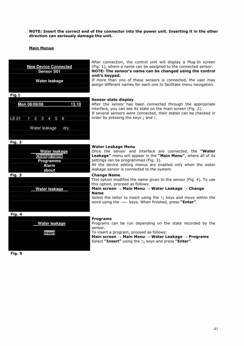
41
NOTE: Insert the correct end of the connector into the power unit. Inserting it in the other direction can seriously damage the unit. .
Main Menue
New Device Connected
Sensor S01
Water leakage
Fig.1
After connection, the control unit will display a Plug-In screen
(Fig. 1), where a name can be assigned to the connected sensor.
NOTE: The sensor’s name can be changed using the control unit’s keypad. If more than one of these sensors is connected, the user may
assign different names for each one to facilitate menu navigation.
___________________________ Mon 08/09/08 13.10
LE 01 1 2 3 4 5 6
Water leakage dry Fig. 2
Sensor state display After the sensor has been connected through the appropriate
interface, you can see its state on the main screen (Fig. 2).
If several sensors were connected, their states can be checked in order by pressing the keys ↓ and ↑.
____Water leakage
Change name Programms
Alarm about
Water Leakage Menu Once the sensor and interface are connected, the “Water Leakage” menu will appear in the “Main Menu”, where all of its settings can be programmed (Fig. 3).
All the device setting menus are enabled only when the water
leakage sensor is connected to the system.
Fig. 3
__Water leakage__
Change Name This option modifies the name given to the sensor (Fig. 4). To use
this option, proceed as follows: Main screen → Main Menu → Water Leakage → Change Name Select the letter to insert using the ↑↓ keys and move within the
word using the →← keys. When finished, press “Enter”.
Fig. 4
__Water leakage
insert
Programs Programs can be run depending on the state recorded by the
sensor.
To insert a program, proceed as follows: Main screen → Main Menu → Water Leakage → Programs Select “Insert” using the ↑↓ keys and press “Enter”.
Fig. 5
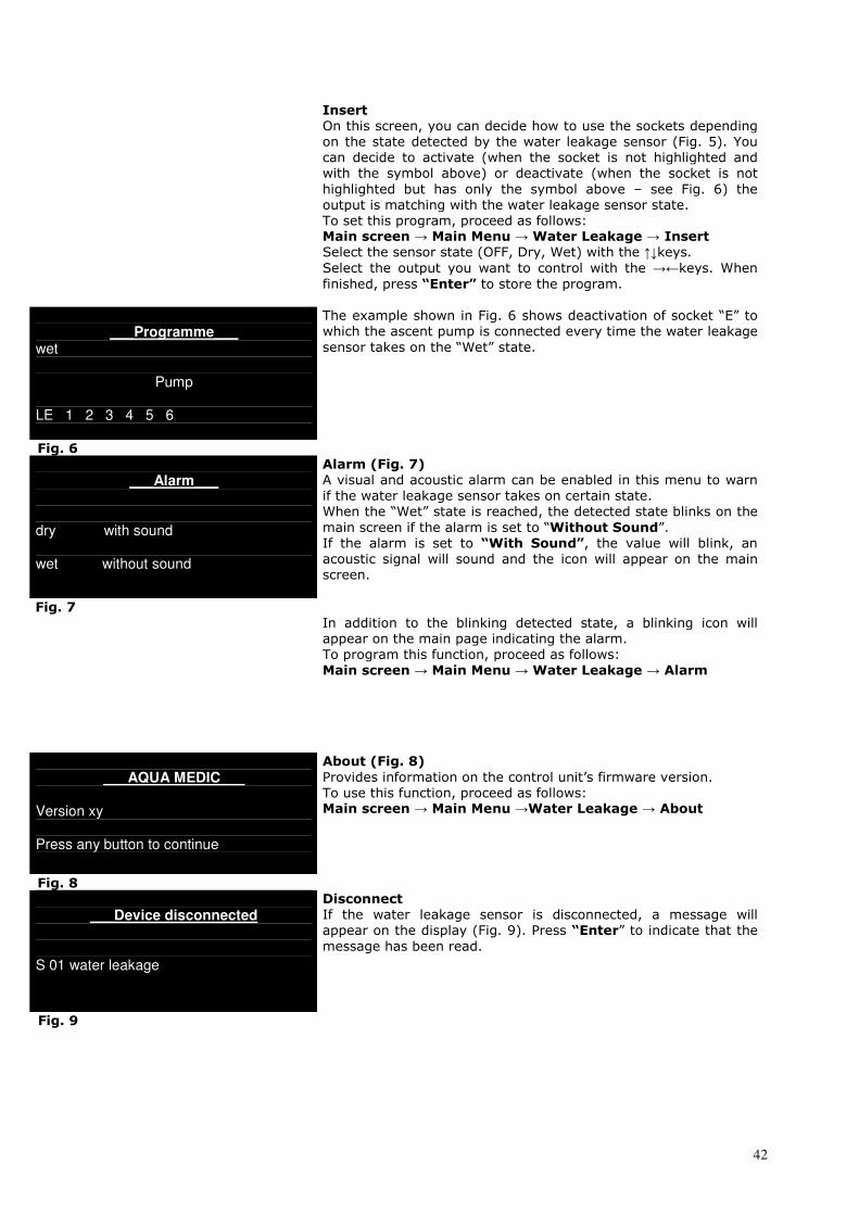
42
Insert On this screen, you can decide how to use the sockets depending
on the state detected by the water leakage sensor (Fig. 5). You
can decide to activate (when the socket is not highlighted and
with the symbol above) or deactivate (when the socket is not
highlighted but has only the symbol above – see Fig. 6) the
output is matching with the water leakage sensor state.
To set this program, proceed as follows: Main screen → Main Menu → Water Leakage → Insert Select the sensor state (OFF, Dry, Wet) with the ↑↓keys.
Select the output you want to control with the →←keys. When
finished, press “Enter” to store the program.
___Programme___
wet
Pump
LE 1 2 3 4 5 6
The example shown in Fig. 6 shows deactivation of socket “E” to
which the ascent pump is connected every time the water leakage
sensor takes on the “Wet” state.
Fig. 6
___Alarm___
dry with sound wet without sound
Alarm (Fig. 7) A visual and acoustic alarm can be enabled in this menu to warn
if the water leakage sensor takes on certain state.
When the “Wet” state is reached, the detected state blinks on the
main screen if the alarm is set to “Without Sound”. If the alarm is set to “With Sound”, the value will blink, an acoustic signal will sound and the icon will appear on the main
screen.
Fig. 7
In addition to the blinking detected state, a blinking icon will
appear on the main page indicating the alarm.
To program this function, proceed as follows:
Main screen → Main Menu → Water Leakage → Alarm
___AQUA MEDIC___
Version xy Press any button to continue
About (Fig. 8) Provides information on the control unit’s firmware version.
To use this function, proceed as follows: Main screen → Main Menu →Water Leakage → About
Fig. 8
___Device disconnected
S 01 water leakage
Disconnect If the water leakage sensor is disconnected, a message will
appear on the display (Fig. 9). Press “Enter” to indicate that the message has been read.
Fig. 9

43
___________________________ Mon 08/09/08 13.10
LE 01 1 2 3 4 5 6
Water leakage ?
?
On the main screen the “?” icon will appear next to the word “Water Leakage” and in the lower left corner (Fig. 10). If the water leakage sensor is reconnected, the control unit will
automatically begin displaying the read state again.
Fig. 10
Water Leakage Sensor The sensor will be mounted below the aquarium or in the cabinet. To make sure that the sensor
works right, it may not get contact to a metal or electrical conducting surface. Salt build ups or other
residues may influence the function as well. As soon as an electrical contact is detected between the
metal pins (e.g. water), the sensor gives alarm.
Position of the sensors

44
Warranty
Should any defect in material or workmanship be found within 12 months of the date of purchase AB
Aqua Medic undertakes to repair or, at our option, replace the defective part free of charge – always
provided the product has been installed correctly, is used for the purpose that was intended by us, is
used in accordance with the operating instructions and is returned to us carriage paid. The warranty
term is not applicable on the all consumable products. Proof of Purchase is required by presentation
of an original invoice or receipt indicating the dealer’s name, the model number and date of
purchase, or a Guarantee Card if appropriate. This warranty may not apply if any model or
production number has been altered, deleted or removed, unauthorised persons or organisations
have executed repairs, modifications or alterations, or damage is caused by accident, misuse or
neglect. We regret we are unable to accept any liability for any consequential loss. Please note that
the product is not defective under the terms of this Warranty where the product, or any of its
component parts, was not originally designed and / or manufactured for the market in which it is
used. These statements do not affect your statutory rights as a customer. If your AB Aqua Medic
product does not appear to be working correctly or appears to be defective please contact your
dealer in the first instance. Before calling your dealer please ensure you have read and understood
the operating instructions. If you have any questions your dealer cannot answer please contact us
Our policy is one of continual technical improvement and we reserve the right to modify and adjust
the specification of our products without prior notification.
AB AQUA MEDIC GmbH - Gewerbepark 24 - 49143 Bissendorf/Germany- - Technical changes reserved – 07/2011