atlantis® atlantis® editor - atlantis weborderatlantis® editor atlantis editor is an enhancement...
TRANSCRIPT
Atlantis®
Atlantis® Editor– User guide

Atlantis®
CONTENTS
Introduction 4
System requirements 4
Installation 4
Google Chrome 8
Viewing feature 10
Toolbar 10
Controls 1 1
Virtual crown 12
Measurement 13
Screenshots 13
Design approval 13
Troubleshooting 14
Editing feature 15
Toolbar 16
Margin adjustments 17
Core adjustments 18
Shoulder and Cut-back adjustments 19
3D handles 20
Advanced controls 21
Atlantis® Crown, Cut-back 22
Atlantis® Crown, Full-contour 23
Atlantis® CustomBase – Core File 24
Atlantis® CustomBase – Crown, Cut-back 25
Atlantis® CustomBase – Crown, Full-contour 26
Atlantis® Conus Abutment, overdenture 27
Reverting changes 28
Design approval 29
Sharing 3D images 29
Violation messages 30
Questions and answers 32
Abutment design terminology 34
This manual is designed as a guide for users of Atlantis WebOrder.
To improve readability for our customers, Dentsply Sirona Implants does not use ® or ™ in body copy. However, Dentsply Sirona Implants does not waive any right to the trademark and nothing herein shall be interpreted to the contrary.
3
Installation
Atlantis® Editor Atlantis Editor is an enhancement of the Atlantis 3D Viewer software that allows the possibility to both view and make limited edits to the proposed abutment design, which can be visualized in realtime.
A proposed abutment design, that is either approved or further modified via Atlantis Editor and submitted, can be processed directly for manufacturing, which can further reduce turnaround time for the case.
The Atlantis Editor also allows for changes to the most common and basic design aspects. It does not allow for changes in the abutment design that might compromise the functional integrity and/or the ability to produce the product. If changes are made outside of acceptable design requirements, the abutment will turn red to indicate that it cannot be accepted for production.
If desired changes cannot be made within the Atlantis Editor functionality, a request can be sent to Dentsply Sirona so an Atlantis Abutment Design Technician can make the change(s) for you. In this case, an updated abutment design will be sent to you for review and approval prior to production. Atlantis abutment design images can still be shared with Atlantis Editor. Click-to-share recipients will be able to view the case images in 3D (software installation required), but the editing feature will not be available to them.
System requirements The minimum system requirements for running Atlantis Editor:
■ A PC running Windows Vista, or higher.
Note: Effective as of April 2014, Windows XP is no longer supported by Microsoft. As a result, technical support and future system updates for Atlantis Editor running in Windows XP will no longer be provided.
■ A 3D-capable graphics card
Compatible web browsers: ■ Internet Explorer (32-bit versions only, IE 6 or newer) ■ Google Chrome (see page 8) ■ Mozilla Firefox
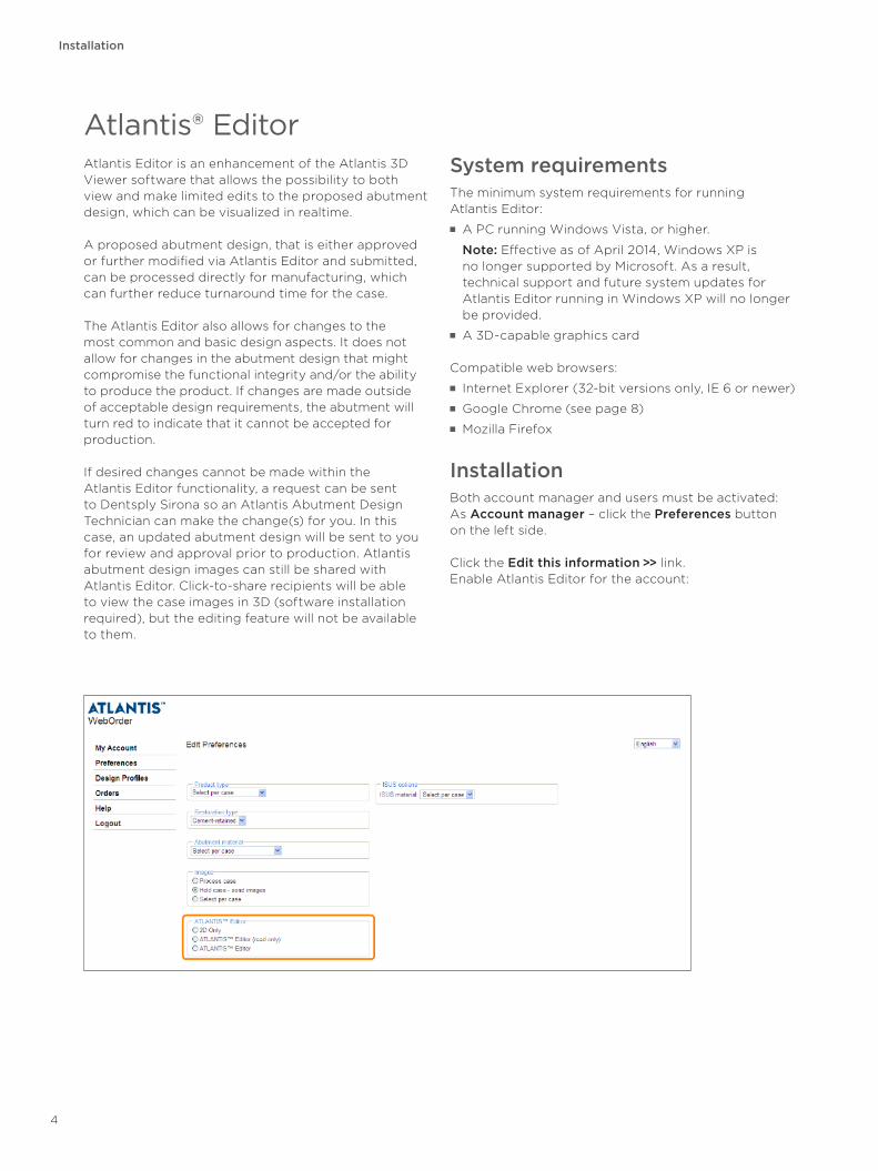
Installation Both account manager and users must be activated:As Account manager – click the Preferences button on the left side.
Click the Edit this information >> link.Enable Atlantis Editor for the account:
4
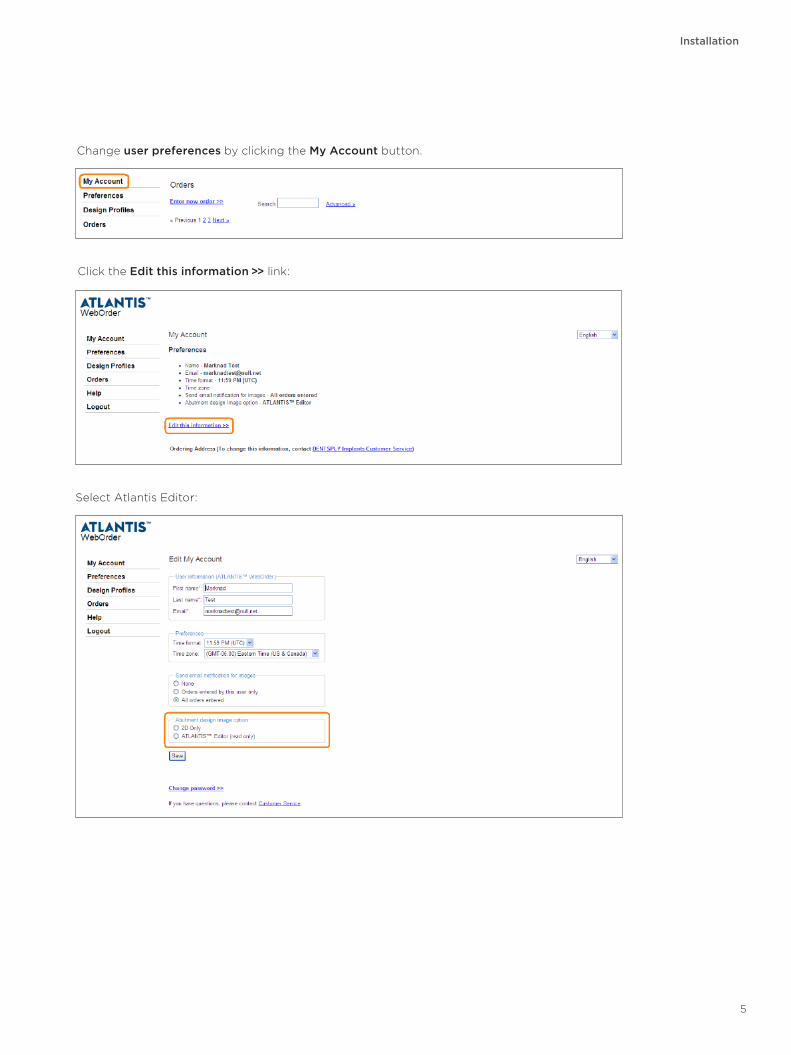
Change user preferences by clicking the My Account button.
Installation
Select Atlantis Editor:
Click the Edit this information >> link:
5
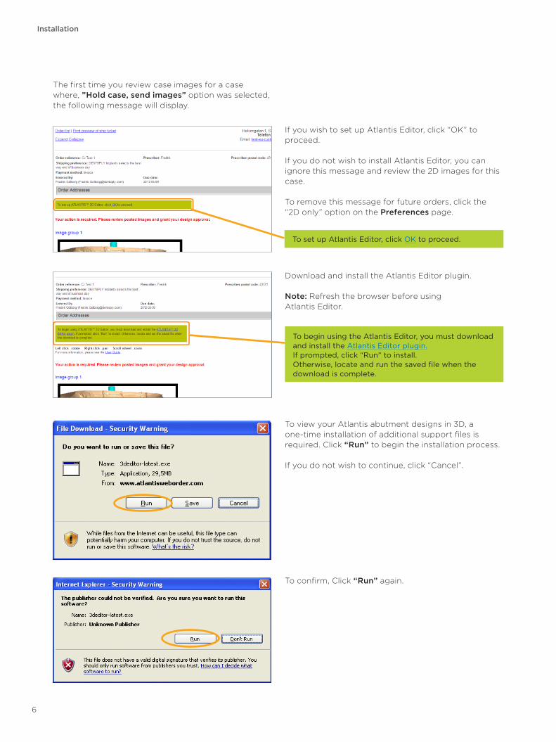
If you wish to set up Atlantis Editor, click “OK” to proceed.
If you do not wish to install Atlantis Editor, you can ignore this message and review the 2D images for this case.
To remove this message for future orders, click the “2D only” option on the Preferences page.
Installation
The first time you review case images for a case where, ”Hold case, send images” option was selected, the following message will display.
To view your Atlantis abutment designs in 3D, a one-time installation of additional support files is required. Click “Run” to begin the installation process.
If you do not wish to continue, click “Cancel”.
To set up Atlantis Editor, click OK to proceed.
To confirm, Click “Run” again.
Download and install the Atlantis Editor plugin.
Note: Refresh the browser before using Atlantis Editor.
To begin using the Atlantis Editor, you must download and install the Atlantis Editor plugin. If prompted, click “Run” to install. Otherwise, locate and run the saved file when the download is complete.
6
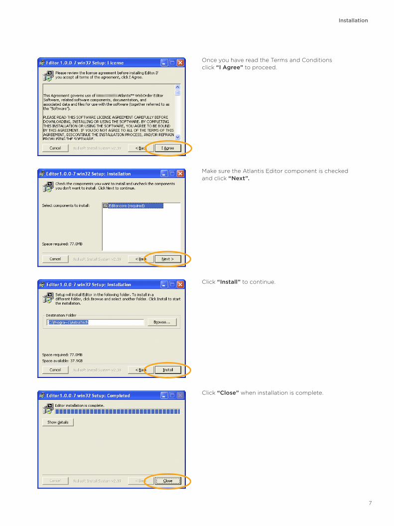
Click “Install” to continue.
Once you have read the Terms and Conditions click “I Agree” to proceed.
Installation
Make sure the Atlantis Editor component is checked and click “Next”.
Click “Close” when installation is complete.
7
Google Chrome
Google Chrome
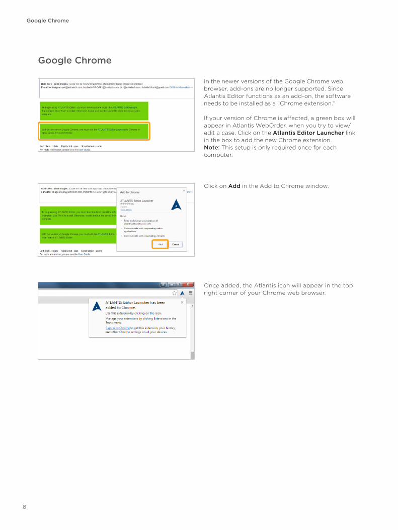
Click on Add in the Add to Chrome window.
Once added, the Atlantis icon will appear in the top right corner of your Chrome web browser.
In the newer versions of the Google Chrome web browser, add-ons are no longer supported. Since Atlantis Editor functions as an add-on, the software needs to be installed as a “Chrome extension.”
If your version of Chrome is affected, a green box will appear in Atlantis WebOrder, when you try to view/edit a case. Click on the Atlantis Editor Launcher link in the box to add the new Chrome extension. Note: This setup is only required once for each computer.
8
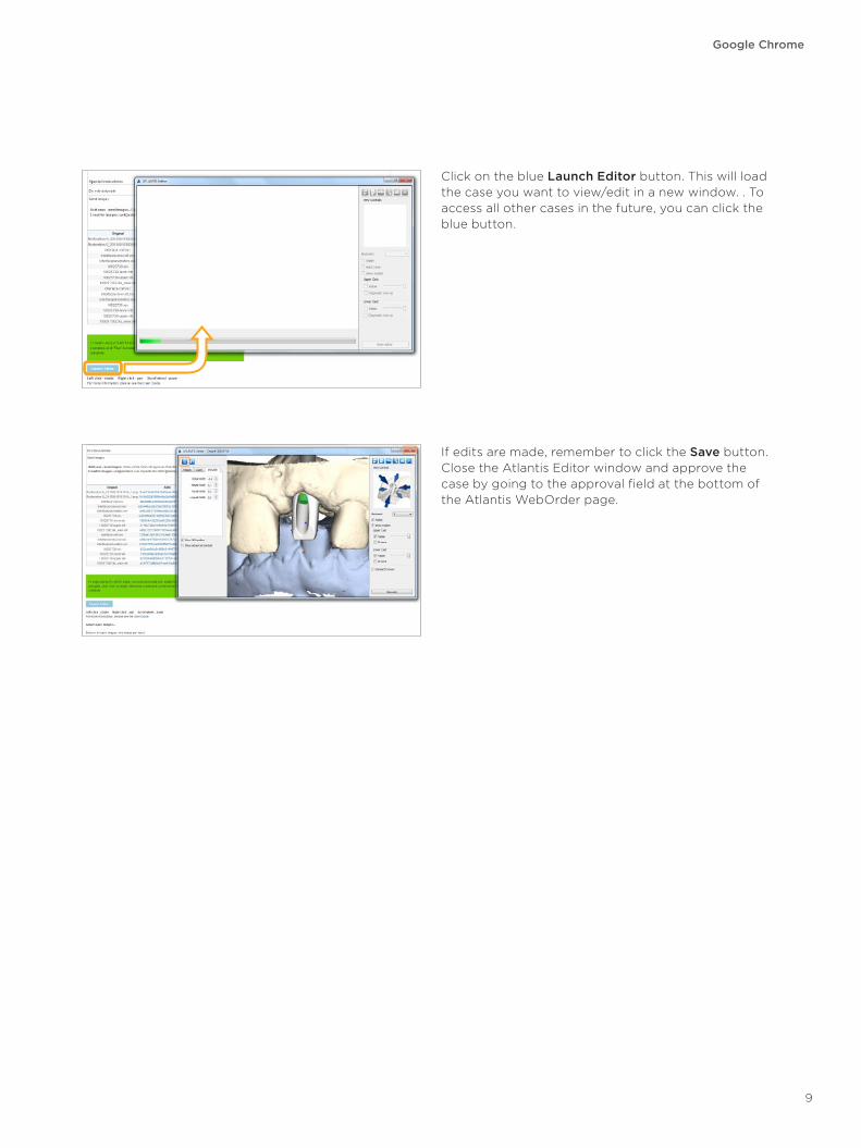
Click on the blue Launch Editor button. This will load the case you want to view/edit in a new window. . To access all other cases in the future, you can click the blue button.
Google Chrome
If edits are made, remember to click the Save button. Close the Atlantis Editor window and approve the case by going to the approval field at the bottom of the Atlantis WebOrder page.
9
Getting started
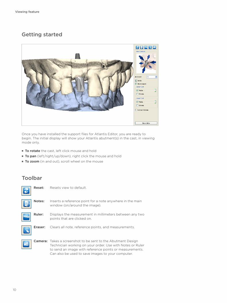
Once you have installed the support files for Atlantis Editor, you are ready to begin. The initial display will show your Atlantis abutment(s) in the cast, in viewing mode only.
■ To rotate the cast, left click mouse and hold ■ To pan (left/right/up/down), right click the mouse and hold ■ To zoom (in and out), scroll wheel on the mouse
Reset: Resets view to default.
Notes: Inserts a reference point for a note anywhere in the main window (on/around the image).
Ruler: Displays the measurement in millimeters between any two points that are clicked on.
Eraser: Clears all note, reference points, and measurements.
Camera: Takes a screenshot to be sent to the Abutment Design Technician working on your order. Use with Notes or Ruler to send an image with reference points or measurements. Can also be used to save images to your computer.
Toolbar
Viewing feature
10
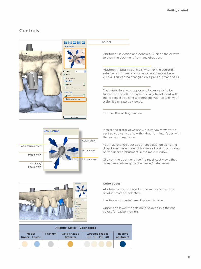
Mesial view
Facial/buccal view
Occlusal/ incisal view
Distal view
Apical view
Lingual view
Controls
Mesial and distal views show a cutaway view of the cast so you can see how the abutment interfaces with the surrounding tissue.
You may change your abutment selection using the dropdown menu under this view or by simply clicking on the desired abutment in the main window.
Click on the abutment itself to reset cast views that have been cut-away by the mesial/distal views.
Getting started
Abutment visibility controls whether the currently selected abutment and its associated implant are visible. This can be changed on a per abutment basis.
Cast visibility allows upper and lower casts to be turned on and off, or made partially translucent with the sliders. If you sent a diagnostic wax-up with your order, it can also be viewed.
Abutment selection and controls. Click on the arrows to view the abutment from any direction.
Toolbar
Enables the editing feature.
Color codes
Abutments are displayed in the same color as the product material selected.
Inactive abutment(s) are displayed in blue.
Upper and lower models are displayed in different colors for easier viewing.
Atlantis® Editor – Color codes
ModelUpper Lower
Titanium Gold-shaded titanium
Zirconia shades00 10 20 30
Inactive abutment
11
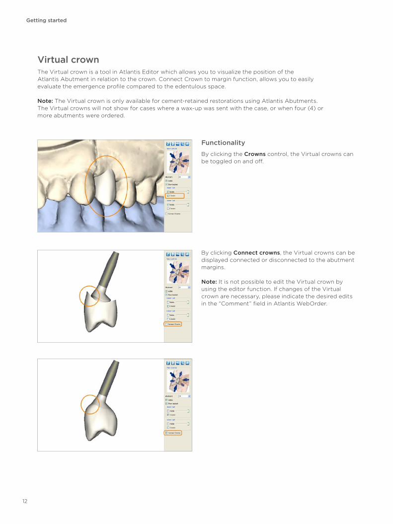
Virtual crownThe Virtual crown is a tool in Atlantis Editor which allows you to visualize the position of the Atlantis Abutment in relation to the crown. Connect Crown to margin function, allows you to easily evaluate the emergence profile compared to the edentulous space.
Note: The Virtual crown is only available for cement-retained restorations using Atlantis Abutments. The Virtual crowns will not show for cases where a wax-up was sent with the case, or when four (4) or more abutments were ordered.
Functionality
By clicking the Crowns control, the Virtual crowns can be toggled on and off.
By clicking Connect crowns, the Virtual crowns can be displayed connected or disconnected to the abutment margins.
Note: It is not possible to edit the Virtual crown by using the editor function. If changes of the Virtual crown are necessary, please indicate the desired edits in the “Comment” field in Atlantis WebOrder.
Getting started
12
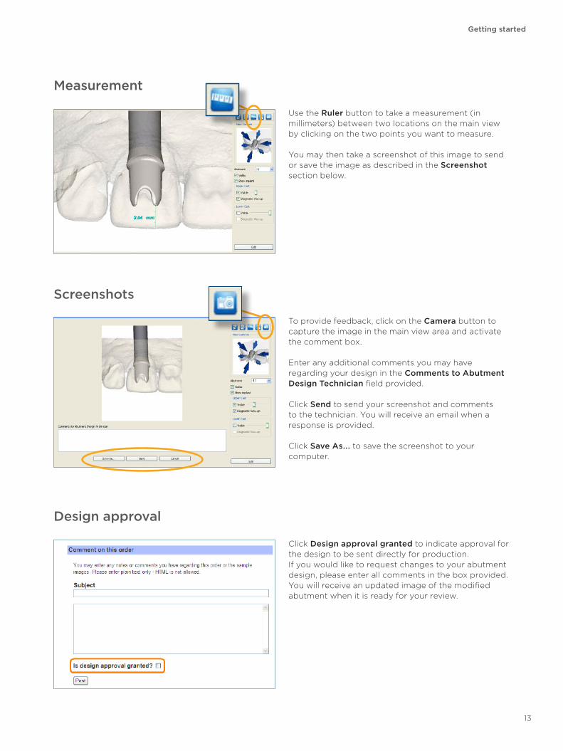
Screenshots
To provide feedback, click on the Camera button to capture the image in the main view area and activate the comment box.
Enter any additional comments you may have regarding your design in the Comments to Abutment Design Technician field provided.
Click Send to send your screenshot and comments to the technician. You will receive an email when a response is provided.
Click Save As... to save the screenshot to your computer.
Measurement
Use the Ruler button to take a measurement (in millimeters) between two locations on the main view by clicking on the two points you want to measure.
You may then take a screenshot of this image to send or save the image as described in the Screenshot section below.
Design approval
Click Design approval granted to indicate approval for the design to be sent directly for production.If you would like to request changes to your abutment design, please enter all comments in the box provided. You will receive an updated image of the modified abutment when it is ready for your review.
Getting started
13
Troubleshooting
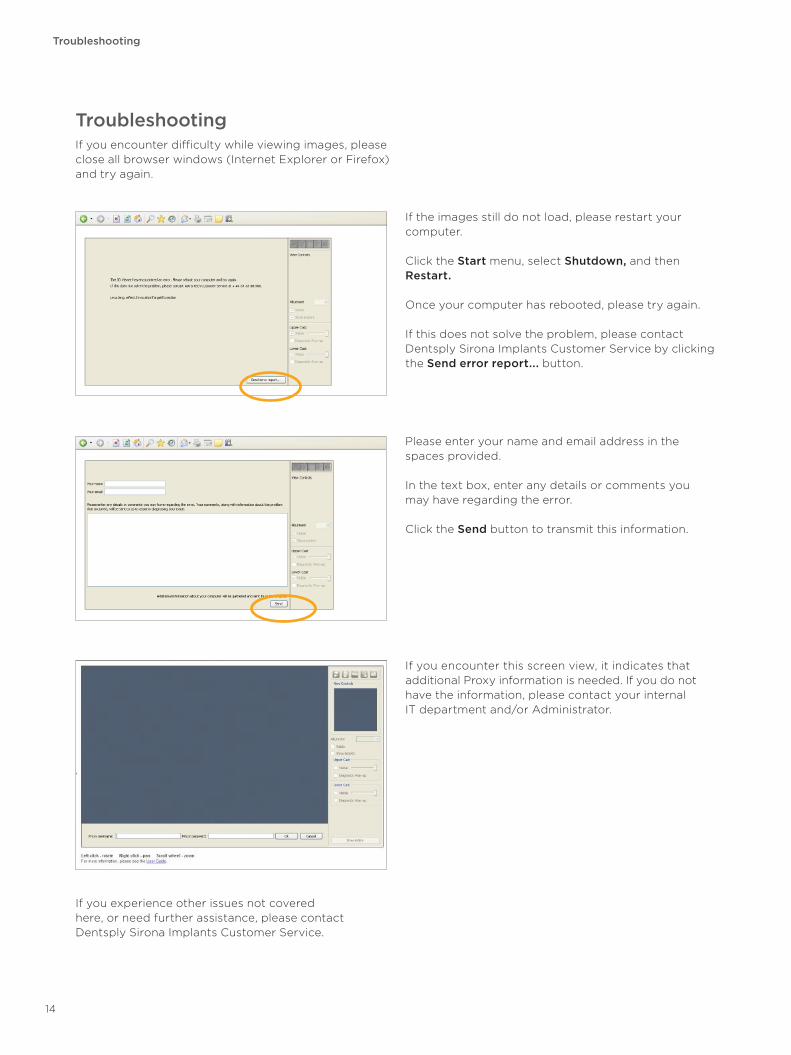
TroubleshootingIf you encounter difficulty while viewing images, please close all browser windows (Internet Explorer or Firefox) and try again.
Please enter your name and email address in the spaces provided.
In the text box, enter any details or comments you may have regarding the error.
Click the Send button to transmit this information.
If you encounter this screen view, it indicates that additional Proxy information is needed. If you do not have the information, please contact your internal IT department and/or Administrator.
If the images still do not load, please restart your computer.
Click the Start menu, select Shutdown, and then Restart.
Once your computer has rebooted, please try again.
If this does not solve the problem, please contact Dentsply Sirona Implants Customer Service by clicking the Send error report... button.
If you experience other issues not covered here, or need further assistance, please contact Dentsply Sirona Implants Customer Service.
14
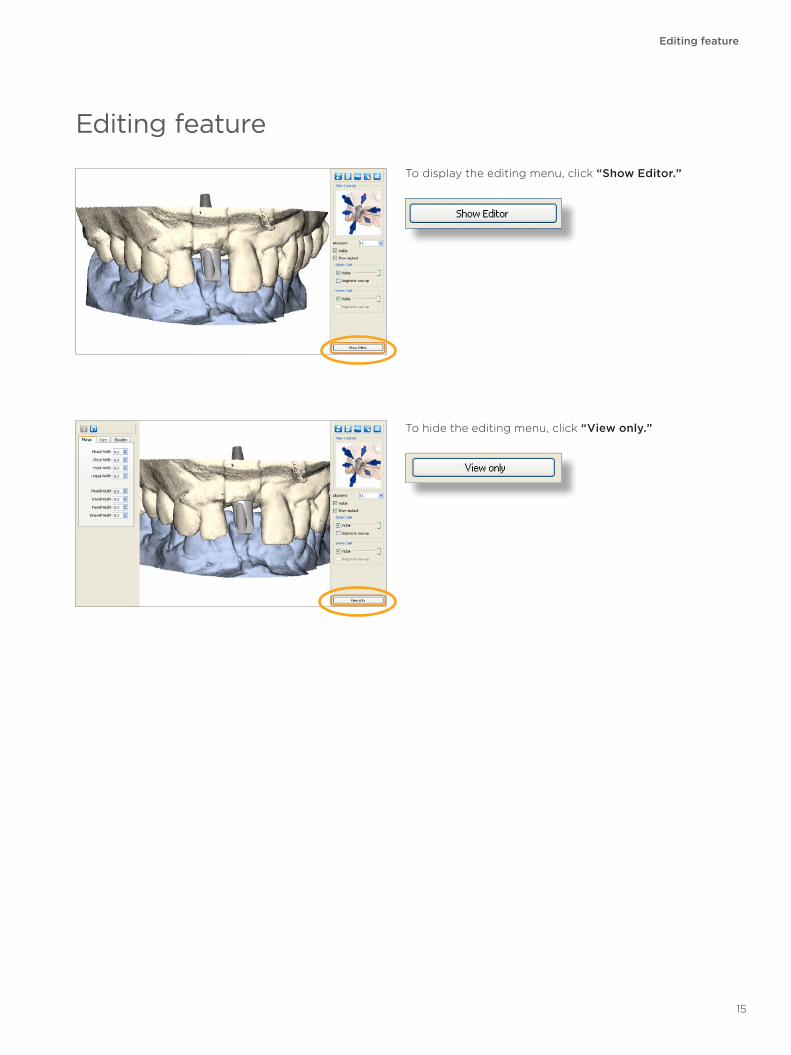
To display the editing menu, click “Show Editor.”
Editing feature
To hide the editing menu, click “View only.”
Editing feature
15
Editing feature
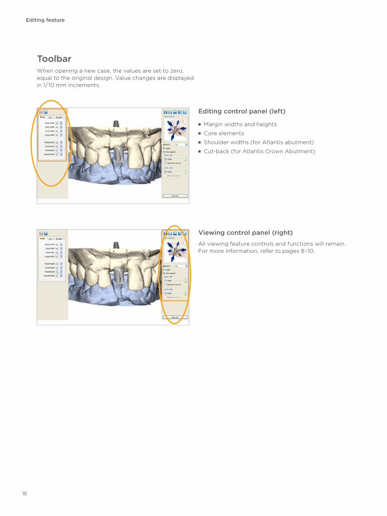
ToolbarWhen opening a new case, the values are set to zero, equal to the original design. Value changes are displayed in 1/10 mm increments.
Editing control panel (left)
■ Margin widths and heights ■ Core elements ■ Shoulder widths (for Atlantis abutment) ■ Cut-back (for Atlantis Crown Abutment)
Viewing control panel (right)
All viewing feature controls and functions will remain. For more information, refer to pages 8–10.
16
Margin adjustments
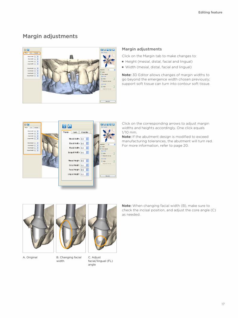
Click on the Margin tab to make changes to: ■ Height (mesial, distal, facial and lingual) ■ Width (mesial, distal, facial and lingual)
Note: 3D Editor allows changes of margin widths to go beyond the emergence width chosen previously; support soft tissue can turn into contour soft tissue.
Editing feature
Click on the corresponding arrows to adjust margin widths and heights accordingly. One click equals 1/10 mm.Note: If the abutment design is modified to exceed manufacturing tolerances, the abutment will turn red. For more information, refer to page 20.
Note: When changing facial width (B), make sure to check the incisal position, and adjust the core angle (C) as needed.
Margin adjustments
A. Original C. Adjust facial/lingual (FL) angle
B. Changing facial width
17
Editing feature
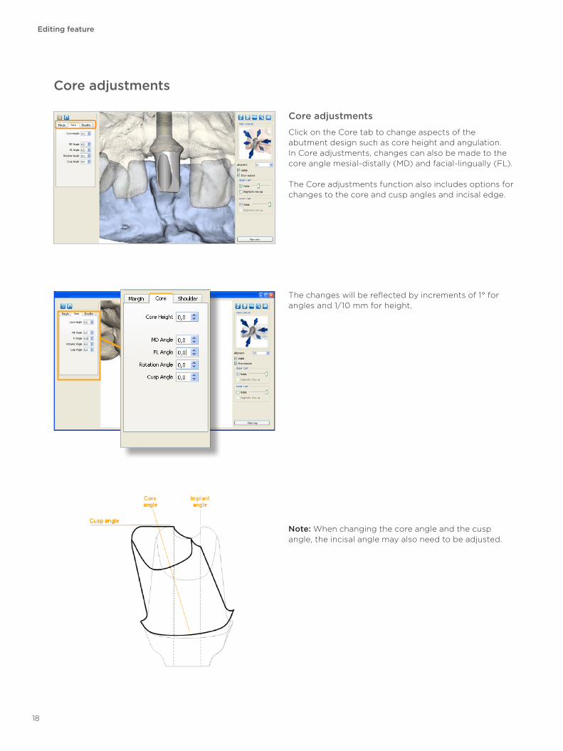
Core adjustments
Core adjustments
Click on the Core tab to change aspects of the abutment design such as core height and angulation. In Core adjustments, changes can also be made to the core angle mesial-distally (MD) and facial-lingually (FL).
The Core adjustments function also includes options for changes to the core and cusp angles and incisal edge.
The changes will be reflected by increments of 1° for angles and 1/10 mm for height.
Note: When changing the core angle and the cusp angle, the incisal angle may also need to be adjusted.
18
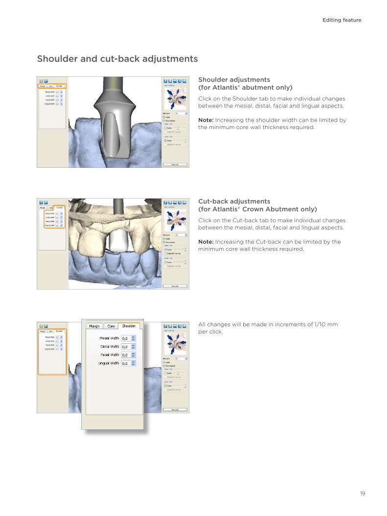
Shoulder adjustments (for Atlantis® abutment only)
Click on the Shoulder tab to make individual changes between the mesial, distal, facial and lingual aspects.
Note: Increasing the shoulder width can be limited by the minimum core wall thickness required.
Editing feature
Shoulder and cut-back adjustments
All changes will be made in increments of 1/10 mm per click.
Cut-back adjustments (for Atlantis® Crown Abutment only)
Click on the Cut-back tab to make individual changes between the mesial, distal, facial and lingual aspects.
Note: Increasing the Cut-back can be limited by the minimum core wall thickness required.
19
Editing feature
3D handles
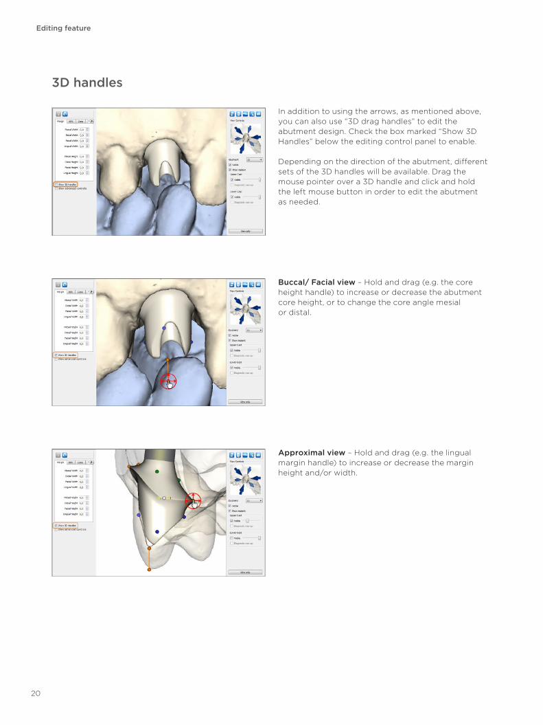
In addition to using the arrows, as mentioned above, you can also use “3D drag handles” to edit the abutment design. Check the box marked “Show 3D Handles” below the editing control panel to enable.
Depending on the direction of the abutment, different sets of the 3D handles will be available. Drag the mouse pointer over a 3D handle and click and hold the left mouse button in order to edit the abutment as needed.
Buccal/ Facial view – Hold and drag (e.g. the core height handle) to increase or decrease the abutment core height, or to change the core angle mesial or distal.
Approximal view – Hold and drag (e.g. the lingual margin handle) to increase or decrease the margin height and/or width.
20
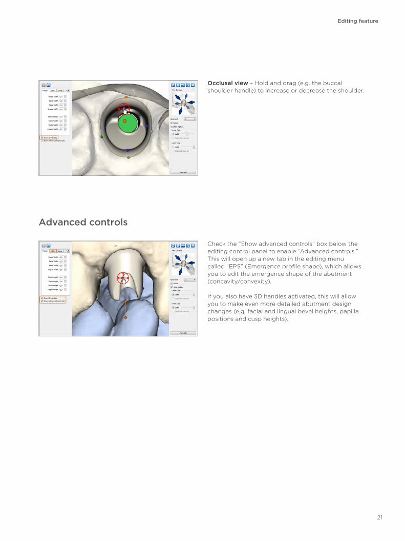
Advanced controls
Check the “Show advanced controls” box below the editing control panel to enable “Advanced controls.” This will open up a new tab in the editing menu called “EPS” (Emergence profile shape), which allows you to edit the emergence shape of the abutment (concavity/convexity).
If you also have 3D handles activated, this will allow you to make even more detailed abutment design changes (e.g. facial and lingual bevel heights, papilla positions and cusp heights).
Occlusal view – Hold and drag (e.g. the buccal shoulder handle) to increase or decrease the shoulder.
Editing feature
21
Atlantis® Crown, Cut-back
Atlantis® Crown, Cut-back
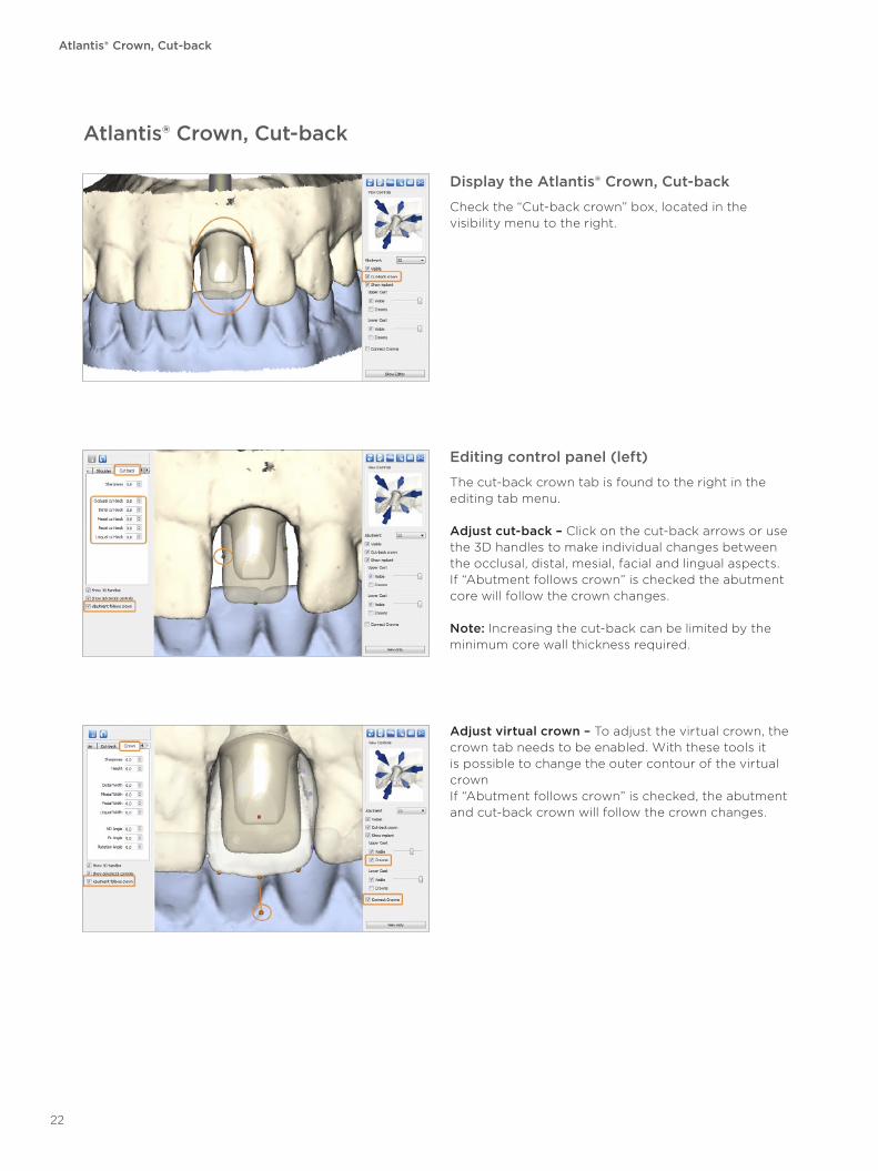
Display the Atlantis® Crown, Cut-back
Check the “Cut-back crown” box, located in the visibility menu to the right.
Editing control panel (left)
The cut-back crown tab is found to the right in the editing tab menu.
Adjust cut-back – Click on the cut-back arrows or use the 3D handles to make individual changes between the occlusal, distal, mesial, facial and lingual aspects. If “Abutment follows crown” is checked the abutment core will follow the crown changes.
Note: Increasing the cut-back can be limited by the minimum core wall thickness required.
Adjust virtual crown – To adjust the virtual crown, the crown tab needs to be enabled. With these tools it is possible to change the outer contour of the virtual crown If “Abutment follows crown” is checked, the abutment and cut-back crown will follow the crown changes.
22
Atlantis® Crown, Full-contour
Atlantis® Crown, Full-contour
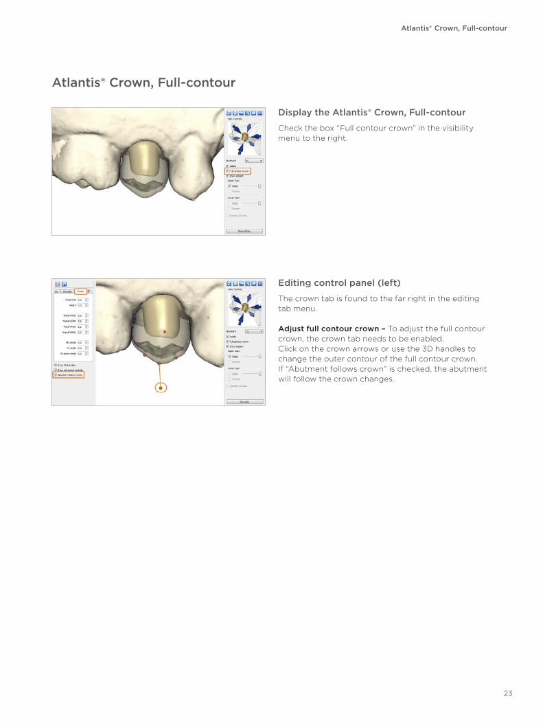
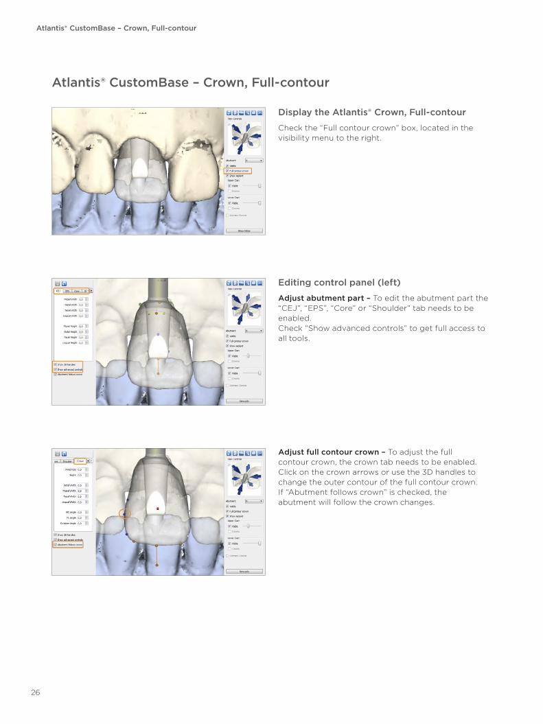
Display the Atlantis® Crown, Full-contour
Check the box “Full contour crown” in the visibility menu to the right.
Editing control panel (left)
The crown tab is found to the far right in the editing tab menu.
Adjust full contour crown – To adjust the full contour crown, the crown tab needs to be enabled. Click on the crown arrows or use the 3D handles to change the outer contour of the full contour crown. If “Abutment follows crown” is checked, the abutment will follow the crown changes.
23
Atlantis® CustomBase – Core File
Atlantis® CustomBase – Core File
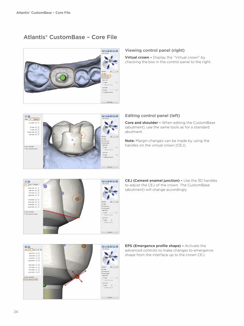
Viewing control panel (right)
Virtual crown – Display the “Virtual crown” by checking the box in the control panel to the right.
Editing control panel (left)
Core and shoulder – When editing the CustomBase (abutment), use the same tools as for a standard abutment.
Note: Margin changes can be made by using the handles on the virtual crown (CEJ).
CEJ (Cement enamel junction) – Use the 3D handles to adjust the CEJ of the crown. The CustomBase (abutment) will change accordingly.
EPS (Emergence profile shape) – Activate the advanced controls to make changes to emergence shape from the interface up to the crown CEJ.
24
Atlantis® CustomBase – Crown, Cut-back
Atlantis® CustomBase – Crown, Cut-back
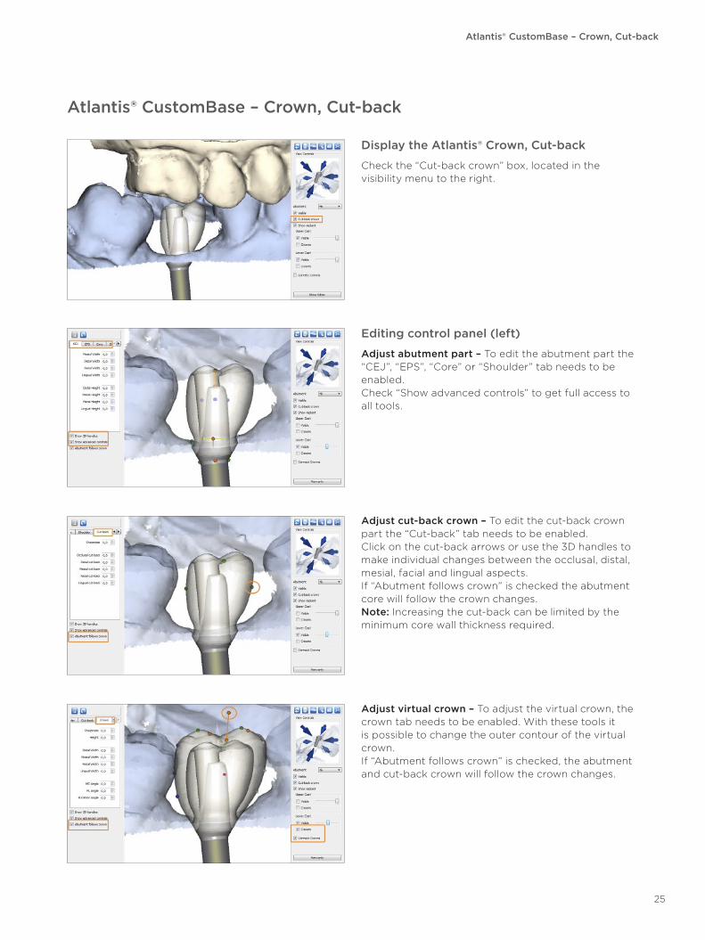
Display the Atlantis® Crown, Cut-back
Check the “Cut-back crown” box, located in the visibility menu to the right.
Editing control panel (left)
Adjust abutment part – To edit the abutment part the “CEJ”, “EPS”, “Core” or “Shoulder” tab needs to be enabled.Check “Show advanced controls” to get full access to all tools.
Adjust cut-back crown – To edit the cut-back crown part the “Cut-back” tab needs to be enabled.Click on the cut-back arrows or use the 3D handles to make individual changes between the occlusal, distal, mesial, facial and lingual aspects.If “Abutment follows crown” is checked the abutment core will follow the crown changes.Note: Increasing the cut-back can be limited by the minimum core wall thickness required.
Adjust virtual crown – To adjust the virtual crown, the crown tab needs to be enabled. With these tools it is possible to change the outer contour of the virtual crown. If “Abutment follows crown” is checked, the abutment and cut-back crown will follow the crown changes.
25
Atlantis® CustomBase – Crown, Full-contour
Atlantis® CustomBase – Crown, Full-contour
Display the Atlantis® Crown, Full-contour
Check the “Full contour crown” box, located in the visibility menu to the right.
Editing control panel (left)
Adjust abutment part – To edit the abutment part the “CEJ”, “EPS”, “Core” or “Shoulder” tab needs to be enabled.Check “Show advanced controls” to get full access to all tools.
Adjust full contour crown – To adjust the full contour crown, the crown tab needs to be enabled. Click on the crown arrows or use the 3D handles to change the outer contour of the full contour crown. If “Abutment follows crown” is checked, the abutment will follow the crown changes.
26
Atlantis® Conus Abutment, overdenture
Atlantis® Conus Abutment, overdenture
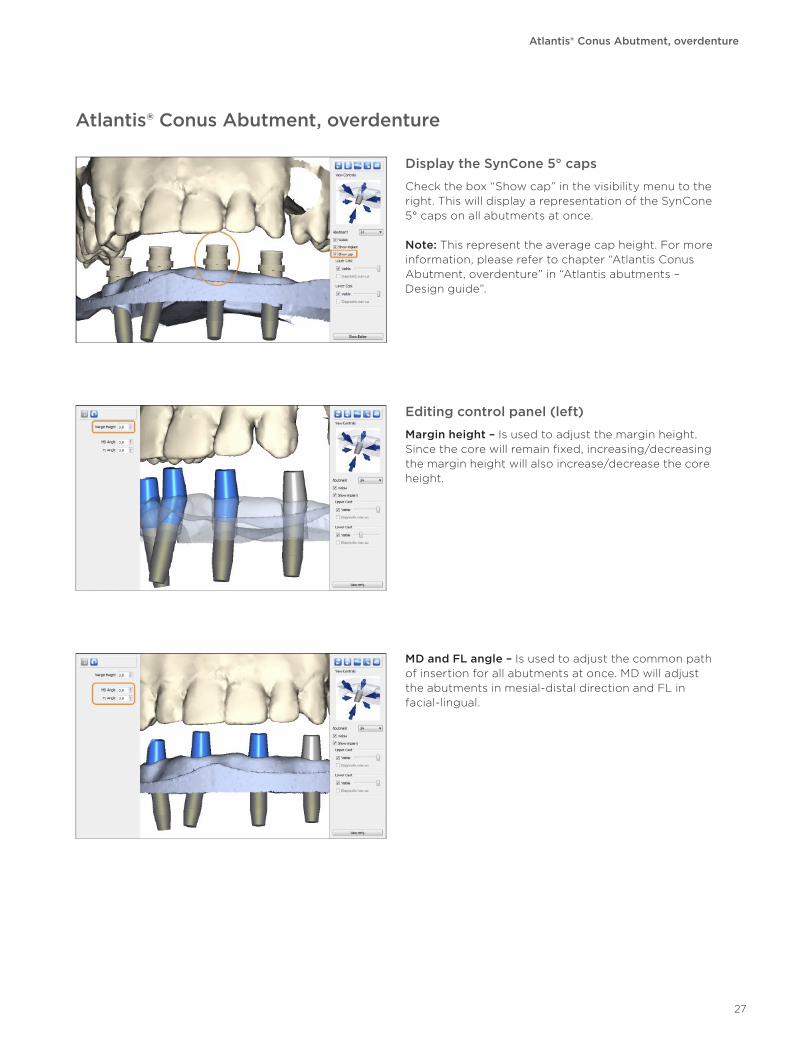
Display the SynCone 5° caps
Check the box “Show cap” in the visibility menu to the right. This will display a representation of the SynCone 5° caps on all abutments at once.
Note: This represent the average cap height. For more information, please refer to chapter “Atlantis Conus Abutment, overdenture” in “Atlantis abutments – Design guide”.
Editing control panel (left)
Margin height – Is used to adjust the margin height. Since the core will remain fixed, increasing/decreasing the margin height will also increase/decrease the core height.
MD and FL angle – Is used to adjust the common path of insertion for all abutments at once. MD will adjust the abutments in mesial-distal direction and FL in facial-lingual.
27
Editing feature
Reverting and saving changes
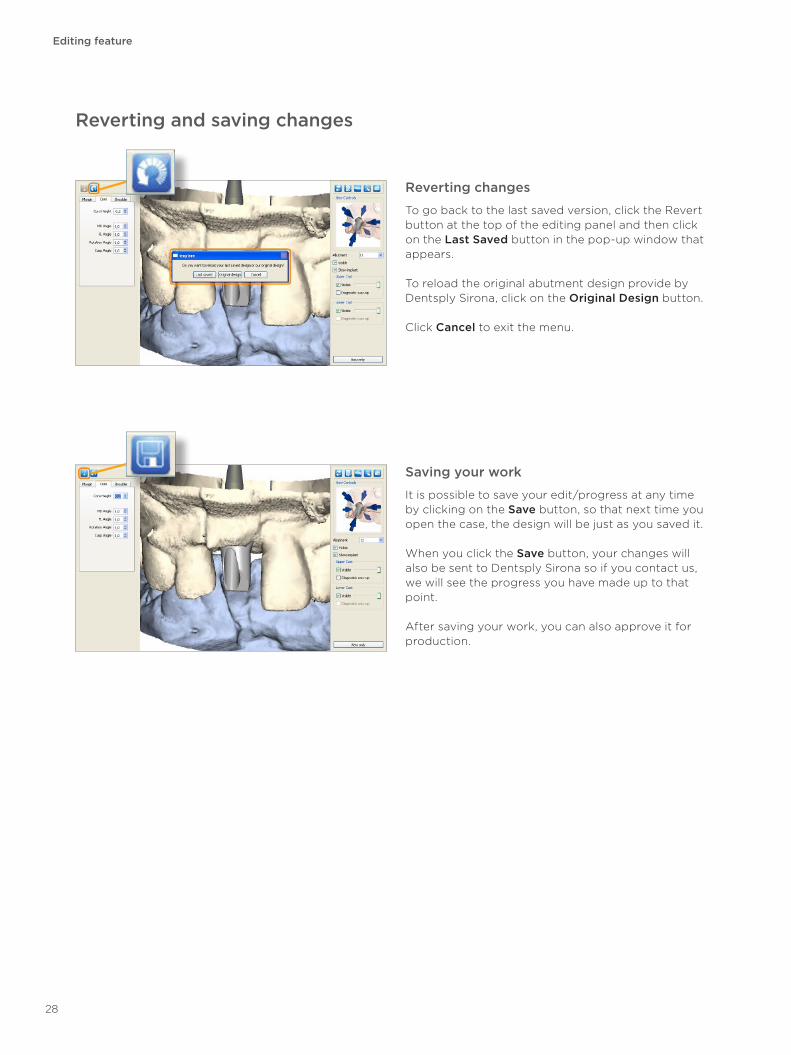
Saving your work
It is possible to save your edit/progress at any time by clicking on the Save button, so that next time you open the case, the design will be just as you saved it.
When you click the Save button, your changes will also be sent to Dentsply Sirona so if you contact us, we will see the progress you have made up to that point.
After saving your work, you can also approve it for production.
Reverting changes
To go back to the last saved version, click the Revert button at the top of the editing panel and then click on the Last Saved button in the pop-up window that appears.
To reload the original abutment design provide by Dentsply Sirona, click on the Original Design button.
Click Cancel to exit the menu.
28
Design approval
Editing feature
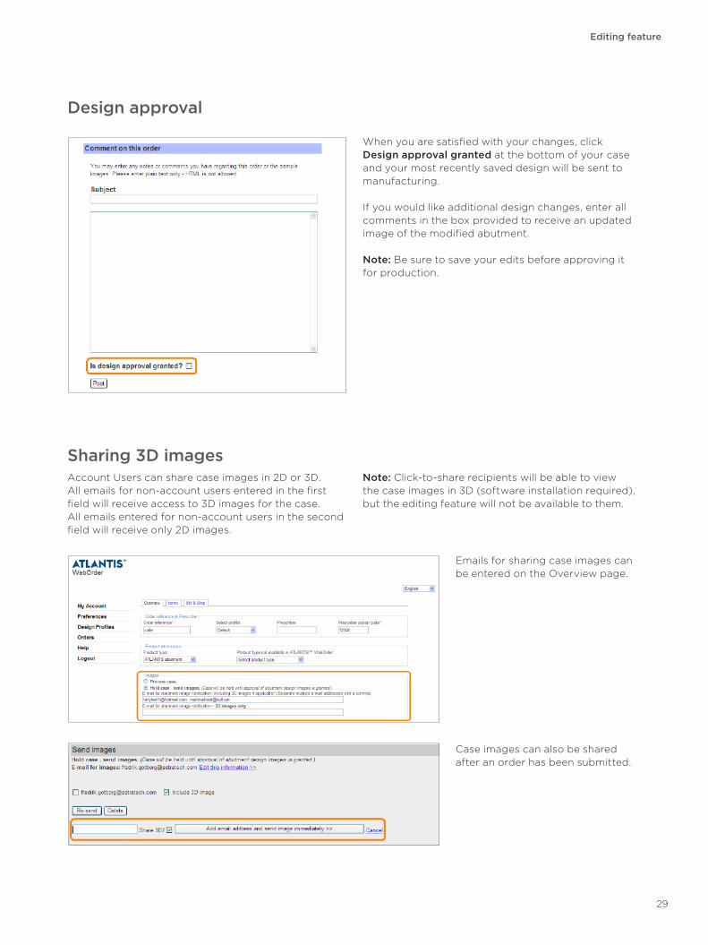
When you are satisfied with your changes, click Design approval granted at the bottom of your case and your most recently saved design will be sent to manufacturing.
If you would like additional design changes, enter all comments in the box provided to receive an updated image of the modified abutment.
Note: Be sure to save your edits before approving it for production.
Emails for sharing case images can be entered on the Overview page.
Case images can also be shared after an order has been submitted.
Sharing 3D imagesAccount Users can share case images in 2D or 3D. All emails for non-account users entered in the first field will receive access to 3D images for the case. All emails entered for non-account users in the second field will receive only 2D images.
Note: Click-to-share recipients will be able to view the case images in 3D (software installation required), but the editing feature will not be available to them.
29
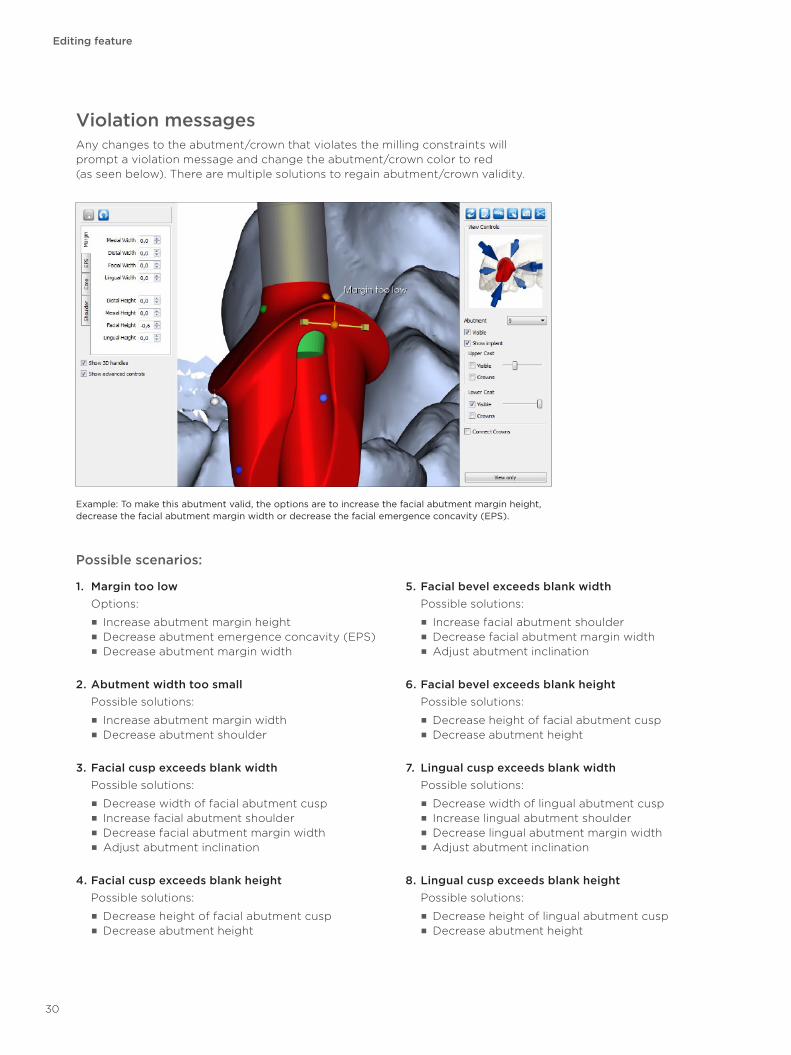
Example: To make this abutment valid, the options are to increase the facial abutment margin height, decrease the facial abutment margin width or decrease the facial emergence concavity (EPS).
Violation messagesAny changes to the abutment/crown that violates the milling constraints will prompt a violation message and change the abutment/crown color to red (as seen below). There are multiple solutions to regain abutment/crown validity.
Possible scenarios:
1. Margin too low Options:
■ Increase abutment margin height ■ Decrease abutment emergence concavity (EPS) ■ Decrease abutment margin width
2. Abutment width too small Possible solutions:
■ Increase abutment margin width ■ Decrease abutment shoulder
3. Facial cusp exceeds blank width Possible solutions:
■ Decrease width of facial abutment cusp ■ Increase facial abutment shoulder ■ Decrease facial abutment margin width ■ Adjust abutment inclination
4. Facial cusp exceeds blank height Possible solutions:
■ Decrease height of facial abutment cusp ■ Decrease abutment height
5. Facial bevel exceeds blank width Possible solutions:
■ Increase facial abutment shoulder ■ Decrease facial abutment margin width ■ Adjust abutment inclination
6. Facial bevel exceeds blank height Possible solutions:
■ Decrease height of facial abutment cusp ■ Decrease abutment height
7. Lingual cusp exceeds blank width Possible solutions:
■ Decrease width of lingual abutment cusp ■ Increase lingual abutment shoulder ■ Decrease lingual abutment margin width ■ Adjust abutment inclination
8. Lingual cusp exceeds blank height Possible solutions:
■ Decrease height of lingual abutment cusp ■ Decrease abutment height
Editing feature
30
Editing feature
9. Lingual bevel exceeds blank width Possible solutions:
■ Increase lingual abutment shoulder ■ Decrease lingual abutment margin width ■ Adjust abutment inclination
10. Lingual bevel exceeds blank height Possible solutions:
■ Decrease height of lingual abutment cusp ■ Decrease abutment height
11. Core exceeds blank width Possible solutions:
■ Increase abutment shoulder ■ Decrease abutment margin width ■ Adjust abutment inclination
12. Margin exceeds blank width Solution:
■ Decrease abutment margin width
13. Screw head exposed Possible solutions:
■ Increase abutment margin width ■ Decrease shoulder width
14. Abutment too high for machining Solution:
■ Decrease abutment height
15. Abutment is too angled from implant Solution:
■ Decrease abutment inclination
16. Margin width too small Solution:
■ Increase abutment margin width
17. Margin height too low Possible solutions:
■ Increase abutment margin height ■ Decrease abutment emergence concavity (EPS) ■ Decrease abutment margin width
18. Invalid core surface Possible solutions:
■ Increase abutment margin width ■ Decrease abutment shoulder width
19. Counterbore may self-intersect Possible solutions:
■ Increase abutment margin width ■ Decrease abutment shoulder width
20. Tool shank interferes with counterbore (Zirconia specific) Possible solutions:
■ Decrease abutment height ■ Adjust cusp angle
21. Core tip too far from counterbore seating (Zirconia specific) Possible solutions:
■ Decrease abutment height ■ Adjust cusp angle
22. Crown exceeds blank width Solution:
■ Decrease crown width
23. Crown exceeds blank height Solution:
■ Decrease crown height
24. Cemented crown exceeds blank width Solution:
■ Decrease crown width
25. Cemented crown exceeds blank height Solution:
■ Decrease crown height
26. Cemented crown wall is too thin Possible solutions:
■ Increase crown width ■ Increase abutment shoulder width ■ Decrease abutment margin width
27. Abutment taper angle below limit for cemented crown Solution:
■ Increase abutment taper angle
28. Keep out violation Possible solutions:
■ Increase abutment margin width ■ Decrease shoulder width
31
Questions and answers
Questions and answers
Editing features
Q: Can I stop working on changes and come back to them later?
A: Yes. You can save your work at any time by clicking on the Save button. Next time you open the case, the abutment design will include any changes you have previously saved.
Q: What should I do if I can’t make the changes I want?
A: Some elements of the abutment design that cannot be modified using Atlantis Editor. If you cannot achieve the design changes you are looking for, please request changes to your case by writing your request in the comment box and sending it in to Dentsply Sirona.
Q: If I’ve made some changes but need help, can Dentsply Sirona see what I’ve done so far?
A: Yes. Once you click the Save button, your changes are registered with Dentsply Sirona. When you contact us, we will see the progress you have made up to that point.
Q: Can I share Atlantis Editor with my clinician?
A: Yes. You will still be able to share case images as usual. If you are sharing 3D case images with someone who has not previously downloaded the viewing software, they will be required to download Atlantis Editor in order to view the images that you have sent. Please note however, that click-to-share recipients can only view case images and will not have editing capabilities.
Q: Does the Atlantis Editor software have safe guards built in that help prevent improper design edits?
A: Yes. There are various parameters within the Atlantis Editor software that help to ensure optimal strength and function of your abutment design:
■ As you change one parameter, other design parameters are changed accordingly to maintain the most proper abutment shape achievable. All elements of the Atlantis abutment design are set to allow for an optimal clinical result. For example, the abutment core taper angle and path of insertion are tightly maintained to ensure the absence of undercuts and a precise fit.
■ All change are monitored as they are made against manufacturing standards. This allows proper control of minimum angles and ensures that abutments are not designed to be larger than the material blank.
If you exceed the blank limit, for example, the abutment will turn red to indicate that the requested design does not meet manufacturing requirements. Note that the blank limit has two elements, a length, which controls the maximum height of the abutment, and a radius, which controls how far the design can go from the screw hole.
Q: Why can’t I see the shape of the planned tooth when I make design changes to the abutment design?
A: For Atlantis Abutment cases ordered without any type of Atlantis Crowns, with 4 or more abutments included in the order, we require you to send in a wax-up. Hence the reason why you cannot see the planned crowns.
Q: Why can’t I control parallelism in Atlantis Editor?
A: To ensure efficiency in your abutment design editing process, certain elements such as parallelism and adjustments to the path of insertion are not included in the Editor because they concern issues about working with multiple teeth. We are always looking for ways to add features, while keeping this tool easy to use for the majority of our customers. In the meantime, you can achieve parallelism by simply requesting it in the parallelism section of Atlantis WebOrder. You can also make adjustments to the path of insertion by noting it in your request to the Atlantis Abutment Design Technician.
Q: Why does one side of my abutment core not move as I change the core angle?
A: For single unit cases, or cases where the units are not splinted, the path of insertion will follow the core angle. In multi-unit cases, however, where the multiple units are to be splinted together, the path of insertion angle for the splinted units also factors into the calculation of the abutment core shape. In these cases, the new core angle is in conflict with the path of insertion, and the tool tries to maintain an optimal balance between the new core angle and the path of insertion. In other words, one side of the abutment matches the core angle, while the other side is limited by the path of insertion.
Q: I want to be able to create curved versus straight base shape. Is that possible?
A: You are able to create concave and convex emergence shapes individually on each side of the abutment by enabling “Advanced controls” in the Atlantis Editor.
32
Q: I want to make the cusps rounder and also change their position and height, is that possible?
A: By enabling “Advanced controls” you are able to do this.
Q: What is a “keep out zone”?
A: There are numerous design parameters built into the sophisticated Atlantis VAD (Virtual Abutment Design) software that help to ensure at the mechanical integrity of the abutment is maintained. The “keep out zone” is the parameter that helps preserve the minimum core thickness needed at the base of an abutment.
Optimizing your Atlantis® abutment designs
Q: How do I adjust the cut-back for an Atlantis crown abutment with the Editor?
A: You adjust the cut-back for a Atlantis Crown Abutment the same way you adjust the shoulder for an Atlantis abutment, but via the Cut-back tab instead. The Cut-back tab (page 19) controls the porcelain support. To find out more about Atlantis Crown Abutment, refer to Atlantis Design Guide.
Q: How do I solve insufficient core retention?
A: If the software determines that the core of the abutment is too small to hold a crown, the abutment will be displayed in red, indicating that it cannot be manufactured to the specifications requested. Changes to the margin position and shoulder widths are good ways to fix this problem.
Q: How do I solve thin core walls?
A: Certain shape combinations result in thin core walls, which the software automatically reshapes to avoid fractures or sharp edges. This can appear as less core height than expected along one of the walls. You can increase the thickness in that area by reducing the corresponding shoulder width, widening the margin position, and sometimes by moving the core angle away from the thin area.
Q: How do I make my margins lower?
A: If you are unable to lower the margin further, this indicates that you have reached the minimum margin height requirement needed for the abutment-to-implant interface.
Q: How do I adjust the height to fit within the blank?
A: When you increase the height of the abutment beyond the maximum manufacturing height limits, the abutment will turn red to indicate that it no longer meets manufacturing requirements. If this happens while you are increasing the abutment height, simply reduce the height until the abutment color changes back to normal. This will also happen if the abutment exceeds the maximum manufacturing width or angle, and/or other design parameters. In all these cases, undo the change you made until the abutment color changes back to normal.
Q: What do nomenclatures such as “core” and “base” mean?
A: Please refer to the “Abutment design terminology” section on page 22.
Q: Does the Atlantis warranty cover changes I made to the original design?
A: The Atlantis warranty covers all Atlantis products that are manufactured.
Q: Is Atlantis Editor compatible with the Mac?
A: No. Mac compatibility for Atlantis Editor is currently not available.
For other questions or issues, please contact Dentsply Sirona Implants Customer Service.
Questions and answers
33
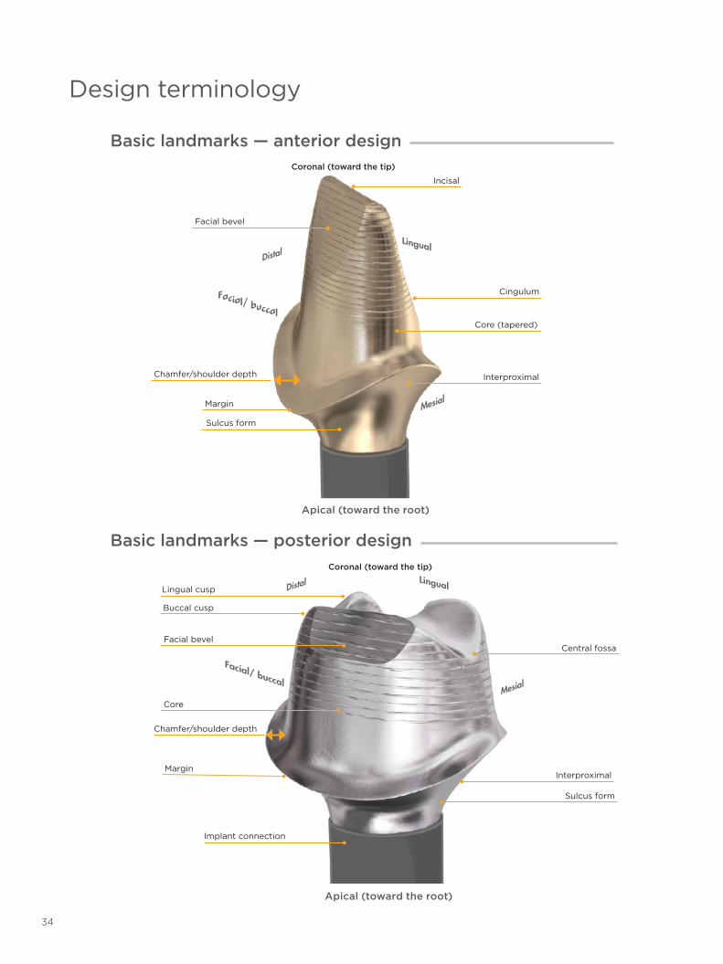
Design terminology
Basic landmarks — anterior designCoronal (toward the tip)
Apical (toward the root)
Facial bevel
Incisal
Margin
Chamfer/shoulder depth
Sulcus form
Interproximal
Core (tapered)
Cingulum
Distal
Mesial
Lingual
Facial/ buccal
Basic landmarks — posterior design
Buccal cusp
Chamfer/shoulder depth
Coronal (toward the tip)
Apical (toward the root)
Lingual cusp
Facial bevel
Core
Margin
Implant connection
Central fossa
Interproximal
Sulcus form
Distal
Mesial
Lingual
Facial/ buccal
34

35
Den
tsp
ly S
iro
na d
oes
no
t w
aive
any
rig
ht t
o it
s tr
adem
arks
by
not
usin
g t
he s
ymb
ols
® o
r ™
. 32
60
46
3-U
SX-1
612
© 2
016
Den
tsp
ly S
iro
na. A
ll ri
ght
s re
serv
ed.
About Dentsply Sirona Implants
Dentsply Sirona Implants offers comprehensive solutions for all phases of implant therapy, including Ankylos®, Astra Tech Implant System® and Xive® implant lines, digital technologies, such as Atlantis® patient-specific solutions and Simplant® guided surgery, Symbios® regenerative solutions, and professional and business development programs, such as STEPPS™. Dentsply Sirona Implants creates value for dental professionals and allows for predictable and lasting implant treatment outcomes, resulting in enhanced quality of life for patients.
About Dentsply Sirona
Dentsply Sirona is the world’s largest manufacturer of professional dental products and technologies, with a 130-year history of innovation and service to the dental industry and patients worldwide. Dentsply Sirona develops, manufactures, and markets a comprehensive solutions offering including dental and oral health products as well as other consumable medical devices under a strong portfolio of world class brands. As The Dental Solutions Company™, Dentsply Sirona’s products provide innovative, high-quality and effective solutions to advance patient care and deliver better, safer and faster dentistry. Dentsply Sirona’s global headquarters is located in York, Pennsylvania, and the international headquarters is based in Salzburg, Austria. The company’s shares are listed in the United States on NASDAQ under the symbol XRAY.
Visit www.dentsplysirona.com for more information about Dentsply Sirona and its products.
THE DENTAL SOLUTIONS COMPANY™