att7023 user’s guide - szaray.com · actions semiconductor co.,ltd single-phase multifunctional...
TRANSCRIPT

ACTIONS SEMICONDUCTOR CO.,LTD Single-phase Multifunctional Energy Metering IC――ATT7023
1
ATT7023 User’s Guide

ACTIONS SEMICONDUCTOR CO.,LTD Single-phase Multifunctional Energy Metering IC――ATT7023
2
TABLE OF CONTENTS
1 Introduction …………………………………………………………………………… 3
§1.1 FEATURES ………………………………………………………………………… 3
§1.2 MAIN TEST PARAMETER …………………………………………………………… 3
§1.3 TYPICAL APPLICATION …………………………………………………………… 3
§1.4 ELECTRIC PARAMETER …………………………………………………………… 4
Electric characteristics …………………………………………………… 4
Ultimate parameter …………………………………………………………… 5
§1.5 FUNCTIONAL BLOCK DIAGRAM …………………………………………………… 6
§1.6 MEASURE BLOCK DIAGRAM ………………………………………………………… 7
§1.7 PIN CONFIGURATION ……………………………………………………………… 8
§1.8 PIN FUNCTION DESCRIPTIONS …………………………………………………… 8
§1.9 APPLICATION SKETCH MAP ……………………………………………………… 10
2 8051 ……………………………………………………………………………………… 11
§2.1 8051 resource …………………………………………………………………… 11
§2.2 Programmed ……………………………………………………………………… 11
3 ENERGY MEASUREMENT …………………………………………………………………… 13
§3.1 Measurement elements ………………………………………………………… 13
§3.2 Data transmission between measure block and 8051 …………………… 13
§3.3 Energy measurement register ……………………………………………… 14
§3.4 Pulse output control ………………………………………………………… 19
4 LCD FUNCTION …………………………………………………………………………… 20
§4.1 LCD driver ……………………………………………………………………… 20
§4.2 Programmed ……………………………………………………………………… 20
§4.3 LCD register …………………………………………………………………… 20
5 LED FUNCTION …………………………………………………………………………… 22
§5.1 LED function introduce ……………………………………………………… 22
§5.2 Programmed ……………………………………………………………………… 22
6 UART FUNCTION …………………………………………………………………………… 24
§6.1 UART function introduce …………………………………………………… 24
§6.2 Programmed ……………………………………………………………………… 24
§6.3 UART register ………………………………………………………………… 24
7 SPI FUNCTION …………………………………………………………………………… 26
§7.1 SPI function introduce ……………………………………………………… 26
§7.2 Programmed ……………………………………………………………………… 26
§7.3 SPI register …………………………………………………………………… 27
8 POWER MANAGE …………………………………………………………………………… 28
§8.1 Power manage introduce ……………………………………………………… 28
§8.2 Standby mode …………………………………………………………………… 28
§8.3 Idle mode ……………………………………………………………………… 28
9 CLOCK CONTROL …………………………………………………………………………… 29
§9.1 Clock control function introduce ………………………………………… 29
§9.2 Programmed ……………………………………………………………………… 29
§9.3 Clock control function register ………………………………………… 29
10 IC ENCAPSULATION …………………………………………………………………… 32
APPENDIX:CORRELATIVE DATUM ABOUT 8051 …………………………………………… 33

ACTIONS SEMICONDUCTOR CO.,LTD Single-phase Multifunctional Energy Metering IC――ATT7023
3
Chapter 1 introduction
§1.1 FEATURES
High accuracy, Supports IEC687/1036, Less than 0.1% error over a dynamic range of 1000
to 1;
Supplies active/reactive energy, voltage RMS, current RMS, and line-voltage frequency;
Supplies active average real power on the programmable frequency output F1/F2 and F3/F4,
or FA1/FA2/FA3/FA4 and FB1/FB2/FB3/FB4;
Supplies active and reactive power output in CF1 and CF2 with programmable frequency;
Uses the one or the sum of the two current to prevent fault condition;
On-chip creep protection (No load threshold);
On-chip reference 2.5V±8%(30ppm/℃ typical) with external overdrive capability;
A PGA in the current channel allows the use of small values of shunt and burden resistance;
Embedded 8051 MCU;
Direct addressing 2K+256byte SRAM, and 32Kbyte OTP ROM;
Two 16-bit timer/counter in 8051, and two 8-bit timer/counter in ATT7023;
Supplies 256byte low-power-consuming SRAM(Standby SRAM), could save data on power cut;
Embedded full-duplex UART serial ports, and a 4-lines SPI serial ports;
Embedded power supply voltage detector, could switch the task mode, reset MCU and
peripherally circuit according to the power supply voltage;
Supplies sufficient I/O ports which could driver EEPROM, etc;
Special 4Common×40Segment LCD driver;
A low-power-consuming real time clock unit, could identify leap year and number of days
in each month automatic; could adjust time precision base on external 32768Hz clock;
Supplies programmable clock pulse output with 1/2/4/8/32/128/1024/32768Hz;
Embedded watch dog;
Supplies 38K frequency wave output, could modulate infrared signal;
Encapsulation: LQFP 100;
Typical current: 7mA;
ATT7023 turn into standby mode when power voltage low to 4.1V±5%, in standby mode, the
typical current is 5uA.
§1.2 MAIN TEST PARAMETER
Voltage RMS
Current RMS
Line-voltage frequency
Active/reactive power
Active/reactive energy
§1.3 TYPICAL APPLICATION
Single-phase watthour metering
Single-phase multi-rate watthour metering
Single-phase multifunctional watthour metering
Single-phase prevent fault watthour metering

ACTIONS SEMICONDUCTOR CO.,LTD Single-phase Multifunctional Energy Metering IC――ATT7023
4
§1.4 ELECTRIC PARAMETER
Electric characteristics (Ta=25℃,AVCC =5V, VCC=5V, fOSC=6.0MHz)
Test object symbol Test condition Test point minimum typ maximum unit
Positive power supply
current
Idd Vv=0.248V
Vi=1.75mV
Power output 7 mA
Standby mode current Idd Power output 5 uA
Reference voltage Vref Vv,Vi=0 Pin5 2.3 2.5 2.7 V
Reference voltage
temperature coefficient
δ Pin5 20 30 60 ppm/℃
Analog input V1P V1N V2P
V2N V3P V3N
±1 V
Maladjustment error
Channel 1
Channel 2
Channel 3
G=1
V1P V1N
V2P V2N
V3P V3N
20
20
20
mV
mV
mV
Plus error
Channel 1
Channel 2
±4%
±4%
Plus matching error
Channel 1
Channel 2
±0.3%
±0.3%
Active power
Error%
e Dynamic
range 1000:1
PF=1
±0.1%
Active power
error%
e Dynamic
range 1000:1
PF=0.5
±0.2 %
Active power
error%
e Dynamic
range 1000:1
PF=0.5
freq=45~65Hz
±0.5 %
Clock input 1 6.0 10 MHz CF1,CF2 VOH
VOL
IOH=5mA
IOL=5mA
Pin8,
Pin9
4.5
0.4
V V
F1 F2 F3 F4
VOH
VOL
IOH=10mA
IOL=10mA
Pin93
Pin96
4.5
0.4
V
V
FA1/FA2/FA3/FA4
FB1/FB2/FB3/FB4
V IOH=10Ma
IOL=10mA
Pin85-92 4.5
0.4
V
V

ACTIONS SEMICONDUCTOR CO.,LTD Single-phase Multifunctional Energy Metering IC――ATT7023
5
Logic input
Input high-level
Input low-level
Input current
Input capacitance
VINH
VINL
IIN
CIN
Other logic
input pin
2.4
0.8
3
10
V
V
uA
pF
Logic output
Output high-level
Output low-level
VOH
VOL
IOH=5mA
IOL=0.8mA
Other logic
output pin
4
0.4
V
V
Ultimate parameter
Object symbol extremum unit
Digital power supply voltage VCC + 7(max) V
analog power supply voltage AVCC + 7(min) V
Current sampling voltage VV -6 ~ +6 V
Voltage sampling voltage Vi -6 ~ +6 V
Working temperature Topr -40 ~ +85 OC
Storage temperature Tstr -65 ~ +150 OC

ACTIONS SEMICONDUCTOR CO.,LTD Single-phase Multifunctional Energy Metering IC――ATT7023
6
§1.5 FUNCTIONAL BLOCK DIAGRAM
MCU
SRAM
ROM
Watch Dog
PowerManagement
Metering Block
LCD Driver
2 sets8-bit Timer
RTC
LED/GPIO
MCU TimingGenarator
SPI
UART2
V2N
V2P
V3P
V3N
VREF
SPICS
SPICKSPIDI
SPIDO
SEG[0:39]
COM[0:3]
GPIO[G/H]
CF2F1F2F3F4
V1N
CF1
StandbySRAM
V1P
XLO
XLI
OSCO
OSCI
LED/GPIO
GPIO
38K
TO
TX2
RX2
TX1
RX1
REVP

ACTIONS SEMICONDUCTOR CO.,LTD Single-phase Multifunctional Energy Metering IC――ATT7023
7
§1.6 MEASURE BLOCK DIAGRAM current channel1
current channel2
voltage channel
current 1 RMS
current 2 RMS
voltage RMS
I1 data
I2 data I data
U data line-voltage freq
I data
U data active power
Reactive power
ADC
LPF
HPF
LPF
SQRT
I1 data I data = I2 data I1 data + I2 data
Zero Cross Calculate Frequency
Samples Counter
90°
LPF
LPF
Reactive energy plus
Active energy plus
Phase emendation
Base on register option

ACTIONS SEMICONDUCTOR CO.,LTD Single-phase Multifunctional Energy Metering IC――ATT7023
8
§1.7 PIN CONFIGURATION
§1.8 PIN FUNCTION DESCRIPTIONS
Pin No. I/O Description
V3P 1 I
V3N 2 I
Analog inputs for channel 3(voltage transducer). The maximum input
signal level is ±660mV and with respect to AGND is ±1V. Both inputs
have internal ESD protection circuitry and in addition an over voltage
of ±6V can be sustained without risk of permanent damage.
V2P 3 I
V2N 4 I
V1P 5 I
V1N 6 I
Analog inputs for channel 1 and channel 2(current transducer). The
maximum input signal level is ±660mV. The maximum signal level at
these pins with respect to AGND is ±1V. Both inputs have internal
ESD protection circuitry and in addition an over voltage of ±6V can
be sustained on these inputs without risk of permanent damage.
VREF 7 I/O This pin provides input/output to the on-chip voltage reference. The
on-chip reference has a nominal value of 2.5V±8% and a typical
temperature coefficient 30ppm/℃。
AGND 8 PWR
This pin provides the ground reference for the analog circuitry in the
ATT7023. This pin should be tied to the analog ground plane or the
quietest ground reference in the system. In order to keep ground noise
around the ATT7023 to a minimum, the quiet ground plane should only
be connected to the analog ground plane at one point.
REVP 9 O This logic output will go logic high when negative power is deteced.

ACTIONS SEMICONDUCTOR CO.,LTD Single-phase Multifunctional Energy Metering IC――ATT7023
9
CF1 10 O Calibration frequency logic output. The CF1 logic output gives active
power information. The driving current is 5mA.
CF2 11 O Calibration frequency logic output. The CF2 logic output gives
reactive power information. The driving current is 5mA.
SPIDO SPIDI SPICK SPICS_
12 13 14 15
O I I I
The four lines of SPI serial interface. There have 300K resistances
to pull high for the input pins.
RX1 16 I Data input for the UART1 serial interface.
TX1 17 O Controlled by register 883AH[bit6](SharpIRDis):
SharpIRDis = 1,Data output for the UART1 serial interface.
SharpIRDis = 0,Data output for the UART1 which modulated by the 38K.
VCC VDD
18/90 30/49/76
PWR
Digital power supply. These pins provide the supply voltage for the
digital circuitry in the ATT7023. The supply voltage should be
maintained at 5V±5% for specified operation. These pins should be
decoupled to digital GND with a 10uF capacitor in parallel with a
ceramic 100nF capacitor.
HOSCI 19 I Master clock input for the system. The clock frequency for specified
operation is 6.000MHz. A 22pF capacitor is built in the ATT7023.
HOSCO 20 O System clock output. A 22pF capacitor is built in the ATT7023.
GND 21/50 75/99
PWR These provide the ground reference for the digital circuitry in the
ATT7023. Which should be connected to the digital ground on the PCB.
LOSCO 22 O Low frequency clock output. A 22pF capacitor is built in the ATT7023.
LOSCI 23 I Low frequency clock input which for RTC and idle mode. This clock
frequency is 32768Hz. A 22pF capacitor is built in the ATT7023.
SBSW_ 24 I Power supplied by mothball battery when power cut. This pin could be
used for awakening internal circuitry.
VBAT 25 PWR This pin is input for 3.6V lithium battery. 38K 26 O This is 38KHz pulse output for infrared modulated wave which from 6MHz.
MODE0 MODE1
27 28
I Working mode control for ATT7023.
TEST_ 29 I Test pin, which is connected to logic high.
GPIOH0~3 31-34 I/O General I/O port H.
TO 35 O This is pulse output for time calibration which from 32768Hz.
GPIOG0~7 36-43 I/O General I/O port G.
TX0 44 O Data output for the UART0 serial interface.
RX0 45 I Data input for the UART0 serial interface. EIRQ1_ 46 I External interrupt 1, active low. Configurable as level-sensitive.
EIRQ0_ 47 I External interrupt 0, active low. Configurable as level-sensitive.
RES_ 48 I Reset pin for the ATT7023, active low. Schmitt Trigger.
VPP 51 PWR Programmed input voltage for OTP ROM. SEG0~7/
NO0~NO7/ GPIOA
52~59
O
Segment 0-7 driver pin.
LED scan bit 0~7 signal output.
General I/O port A.

ACTIONS SEMICONDUCTOR CO.,LTD Single-phase Multifunctional Energy Metering IC――ATT7023
10
SEG8~15/ A~P/
GPIOB 60~67 O
Segment 8-15 driver pin.
LED scan sect 0~7 signal output. General I/O port B.
SEG16~31/ GPIOC GPIOD
68-77 78-85
O
I/O
Segment 16-31 driver pin.
General I/O port C. General I/O port D.
FA1~FA4, FB1~FB4/
GPIOE/ SEG32~39
86-89 91-94
O
I/O O
Low frequency pulse output. Be used for driving 2-phase 4-step meter.
The driving current is 10mA.
General I/O port E.
Segment 32-39 driver pin.
COM0~3/
F1~F4/
GPIOF0~3
95-98
O O
I/O
Common 8-15 driver pin.
Low frequency pulse output. Be used for driving 2-phase 2-step meter.
The driving current is 10mA.
General I/O port F.
AVCC 100 PWR Analog power supply. This pin provides the supply voltage for the
analog circuitry in the ATT7023. The supply should be maintained at
5V±5% for specified operation.
Notice: There have 300K resistances to pull high for the input pins. §1.9 APPLICATION SKETCH MAP
V1P
V1N
V2P
V2N
V3P
V3N
ATT7023
COM[0:3]
SEG[1:40]
LCD
SPI datatransmisson
CF1
CF2
IL+
IL-
IN+
IN-
VL+
VL- emendation
ACTIONS SEMICONDUCTOR CO.,LTD Single-phase Multifunctional Energy Metering IC――ATT7023
11
Chapter 2 8051
§2.1 8051 resource
The external clock frequency for 8051 is 6.000MHz, and the internal work frequency for 8051
is optional via register 884AH:Bit[5,4]. The default value is 6.000MHz. The 8051 provide one
UART serial interface (UART0), two counter/timer (Timer0 and Timer1), and five interrupt sources.
Internal SRAM: 256 byte(00H ~ FFH), hereinto, 80H~FFH are special function registers;
External SRAM: 2K byte(8000H ~ 87FFH);
Registers: 256 byte(8800H ~ 88FFH);
Standby SRAM: 256 byte(8900H ~ 89FFH). Power supplied by mothball battery when power cut,
could be used for saving data;
OTP ROM: 32K byte (0000H ~ 7FFFH);
Reset address: 0000H
§2.2 Programmed
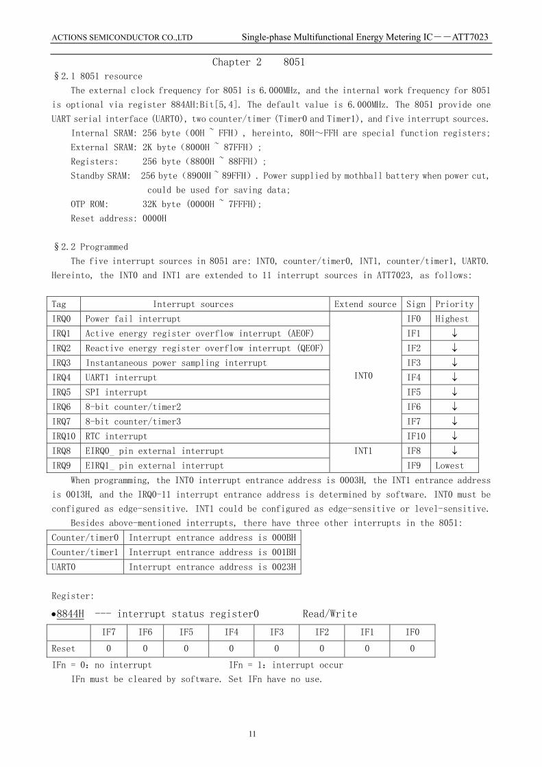
The five interrupt sources in 8051 are: INT0, counter/timer0, INT1, counter/timer1, UART0.
Hereinto, the INT0 and INT1 are extended to 11 interrupt sources in ATT7023, as follows:
Tag Interrupt sources Extend source Sign Priority
IRQ0 Power fail interrupt IF0 Highest
IRQ1 Active energy register overflow interrupt (AEOF) IF1 ↓ IRQ2 Reactive energy register overflow interrupt (QEOF) IF2 ↓ IRQ3 Instantaneous power sampling interrupt IF3 ↓ IRQ4 UART1 interrupt IF4 ↓ IRQ5 SPI interrupt IF5 ↓ IRQ6 8-bit counter/timer2 IF6 ↓ IRQ7 8-bit counter/timer3 IF7 ↓ IRQ10 RTC interrupt
INT0
IF10 ↓ IRQ8 EIRQ0_ pin external interrupt IF8 ↓ IRQ9 EIRQ1_ pin external interrupt
INT1
IF9 Lowest
When programming, the INT0 interrupt entrance address is 0003H, the INT1 entrance address
is 0013H, and the IRQ0-11 interrupt entrance address is determined by software. INT0 must be
configured as edge-sensitive. INT1 could be configured as edge-sensitive or level-sensitive.
Besides above-mentioned interrupts, there have three other interrupts in the 8051:
Counter/timer0 Interrupt entrance address is 000BH
Counter/timer1 Interrupt entrance address is 001BH
UART0 Interrupt entrance address is 0023H
Register:
•8844H --- interrupt status register0 Read/Write
IF7 IF6 IF5 IF4 IF3 IF2 IF1 IF0
Reset 0 0 0 0 0 0 0 0
IFn = 0:no interrupt IFn = 1:interrupt occur
IFn must be cleared by software. Set IFn have no use.
ACTIONS SEMICONDUCTOR CO.,LTD Single-phase Multifunctional Energy Metering IC――ATT7023
12
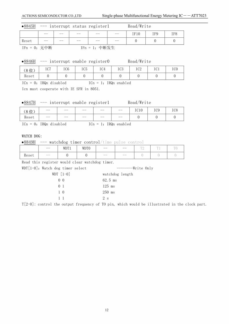
•8845H --- interrupt status register1 Read/Write
-- -- -- -- -- IF10 IF9 IF8
Reset -- -- -- -- -- 0 0 0
IFn = 0:无中断 IFn = 1:中断发生
•8846H --- interrupt enable register0 Read/Write
(8 位) IC7 IC6 IC5 IC4 IC3 IC2 IC1 IC0
Reset 0 0 0 0 0 0 0 0
ICn = 0:IRQn disabled ICn = 1:IRQn enabled
Icn must cooperate with IE SFR in 8051.
•8847H --- interrupt enable register1 Read/Write
(8 位) -- -- -- -- -- IC10 IC9 IC8
Reset -- -- -- -- -- 0 0 0
ICn = 0:IRQn disabled ICn = 1:IRQn enabled
WATCH DOG:
•8849H --- watchdog timer control ///tttiiimmmeee pppuuulllssseee cccooonnntttrrrooolll -- WDT1 WDT0 -- -- TTT222 TTT111 TTT000
Reset -- 0 0 -- -- 000 000 000
Read this register would clear watchdog timer.
WDT[1-0]:Watch dog timer select --------Write Only
WDT [1-0] watchdog length
0 0 62.5 ms
0 1 125 ms
1 0 250 ms
1 1 2 s
T[2-0]: control the output frequency of TO pin, which would be illustrated in the clock part.

ACTIONS SEMICONDUCTOR CO.,LTD Single-phase Multifunctional Energy Metering IC――ATT7023
13
Chapter 3 ENERGY MEASUREMENT
§3.1 Measurement elements
Sampling frequency: 31.25KHz
Pulse output: active energy CF1
Reactive energy CF2
Active meter output F1 F2/FA1 FA2 FA3 FA4
Active meter output F3 F4/FB1 FB2 FB3 FB4
Calibration mode:
Simple mode: change the resistivity of voltage channel.
Software mode: write the calibration register via software.
Threshold: judge the current threshold base on the active power.
Elements: Multiplication, addition and digital filtering of input voltage and current
signals achieve calculation of active power. The over sampling of sigma-delta
ADC guarantees sampling rate of input signals. And the active power is
calculation according to the formula P= ∑=
•N
nnInU
N 0
)()(1.
Calculation of active power is similar to the calculation of active power. The
only difference is that the voltage signals are 90-degree phase shifted.
There have two current channels are sampling. The calculation use current channel
1 or current channel 2, or their sum, which is determined by software.
§3.2 Data transmission between measure block and 8051
Within the ATT7023, the measure block and 8051 communicate with parallel interface. The
8051 could access measure register directly.
Measure register consists of control register, calibration register, data register.
Control register: control the working mode of measure block
ADC plus select Prevent fault mode Instantaneous power sampling velocity select (1.95K/3.90K/7.81K/15.62K/31.25K) CF frequency programmable select Energy addition mode select:
MODE1: absolute value addition
MODE2: positive/negative addition
Fault sign/reverse active power register Measure reset and start/stop which controlled by software
Calibration register:8051 write calibration data to calibration register
Active energy plus (channel 1) Gp1 16-bits Reactive energy plus (channel 1) Gq1 16-bits Phase calibration (channel 1) Gphs1 16-bits Active energy plus (channel 2) Gp2 16-bits
Reactive energy plus (channel 2) Gq2 16-bits Phase calibration (channel 2) Gphs2 16-bits HF high frequency output HF 16-bits F1/F2 low frequency output LF 8-bits

ACTIONS SEMICONDUCTOR CO.,LTD Single-phase Multifunctional Energy Metering IC――ATT7023
14
The plus and phase calibration register are both use binary complement system, the MSB
is symbol bit.
Data register:transmit data to 8051
Current channel 1 RMS Irms1 24-bits (Unsigned)
Current channel 2 RMS Irms2 24-bits (Unsigned)
Voltage RMS Urms 24-bits (Unsigned) Line-voltage frequency Freq 16-bits (Unsigned) Active energy Ep 40-bits (Signed)
Reactive energy Eq 40-bits (Signed)
Active power wave P 24-bits (Signed)
Reactive power wave Q 24-bits (Signed)
Interrupt:
Active energy register overflow interrupt (AEOF)
Reactive energy register overflow interrupt (AEOF)
Instantaneous power sampling interrupt
§3.3 Energy measurement register
Sampling control/ADC plus select register 88D0H Read/Write
PGA1 PGA0 -- QMODE PMODE Spl2 Spl1 Spl0
Reset 0 0 -- 0 0 0 0 0
Power sampling velocity:
PMode=0:Active energy addition mode: absolute value addition
=1:Active energy addition mode: positive/negative addition
QMode=0:Reactive energy addition mode: absolute value addition
=1:Reactive energy addition mode: positive/negative addition
PAG1,PAG0:Adjust to the PGA plus of channel 1 and channel 2.
Measure reset and start/stop control register 88D1H Write Only
-- -- -- -- -- -- Run/Stop Reset
Spl2 Spl1 Spl0 Power sampling velocity
0 0 0 1.75k Hz
0 0 1 3.49k Hz
0 1 0 6.99k Hz
0 1 1 13.98k Hz
1 X X 27.97k Hz
Bit address Bit symbol explain
7,6 PGA1,PGA0 PGA1 and PGA2 (current channel) plus select:
00=x1 01=x8 10=x16 11=x32

ACTIONS SEMICONDUCTOR CO.,LTD Single-phase Multifunctional Energy Metering IC――ATT7023
15
Reset -- -- -- -- -- -- 0 0
Reset:Set this bit would clear energy register (Ep/Eq), cleared by hardware.
Run/Stop=0:seart measure Run/Stop=1:stop measure active/reactive energy.
Fault sign/reverse active power register 88D4H
-- -- -- -- -- CIADD Revp Fault
Reset -- -- -- -- -- 0 0 0
Fault: Read/Write
Fault =0:Select channel 1 as current input channel
Fault =1:Select channel 2 as current input channel
Revp: Will be set to 1 when negative power is detected till positive power is detected again.
Read Only
CIADD: CIADD =0:channel 1 and channel 2 don’t add. Read/Write
CIADD =1:channel 1 and channel 2 add as current channel.
CIADD Fault
0 0 Select channel 1 as current input channel
0 1 Select channel 2 as current input channel
1 X Select the sum of channel 1 and channel 2 as current input channel
HF frequency control register
High Byte 88D5H Read/Write
--- --- --- --- HF11 HF10 HF09 HF08
Reset --- --- --- --- 0 1 0 0
Low Byte 88D6H Read/Write
HF07 HF06 HF05 HF04 HF03 HF02 HF01 HF00
Reset 0 0 0 0 0 0 0 0
Control the output frequency of CF1.
Active energy plus (channel 1) Gp1
High Byte 88D7H Read/Write
GPD15 GPD14 GPD13 GPD12 GPD11 GPD10 GPD09 GPD08
Reset 0 0 0 0 0 0 0 0
Low Byte 88D8H Read/Write
GPD07 GPD06 GPD05 GPD04 GPD03 GPD02 GPD01 GPD00
Reset 0 0 0 0 0 0 0 0
Reactive energy plus (channel 1) Gq1
High Byte 88D9H Read/Write
GQD15 GQD14 GQD13 GQD12 GQD11 GQD10 GQD09 GQD08

ACTIONS SEMICONDUCTOR CO.,LTD Single-phase Multifunctional Energy Metering IC――ATT7023
16
Reset 0 0 0 0 0 0 0 0
Low Byte 88DAH Read/Write
GQD07 GQD06 GQD05 GQD04 GQD03 GQD02 GQD01 GQD00
Reset 0 0 0 0 0 0 0 0
Phase calibration (channel 1) Gphs1
High Byte 88DBH Read/Write
GPFD15 GPFD14 GPFD13 GPFD12 GPFD11 GPFD10 GPFD09 GPFD08
Reset 0 0 0 0 0 0 0 0
Low Byte 88DCH Read/Write
GPFD07 GPFD06 GPFD05 GPFD04 GPFD03 GPFD02 GPFD01 GPFD00
Reset 0 0 0 0 0 0 0 0
Active energy plus (channel 2) Gp2
High Byte 88DDH Read/Write
GPD15 GPD14 GPD13 GPD12 GPD11 GPD10 GPD09 GPD08
Reset 0 0 0 0 0 0 0 0
Low Byte 88DEH Read/Write
GPD07 GPD06 GPD05 GPD04 GPD03 GPD02 GPD01 GPD00
Reset 0 0 0 0 0 0 0 0
Reactive energy plus (channel 2) Gq2
High Byte 88DFH Read/Write
GQD15 GQD14 GQD13 GQD12 GQD11 GQD10 GQD09 GQD08
Reset 0 0 0 0 0 0 0 0
Low Byte 88E0H Read/Write
GQD07 GQD06 GQD05 GQD04 GQD03 GQD02 GQD01 GQD00
Reset 0 0 0 0 0 0 0 0
Phase calibration (channel 2) Gphs2
High Byte 88E1H Read/Write
GPFD15 GPFD14 GPFD13 GPFD12 GPFD11 GPFD10 GPFD09 GPFD08
Reset 0 0 0 0 0 0 0 0
Low Byte 88E2H Read/Write
GPFD07 GPFD06 GPFD05 GPFD04 GPFD03 GPFD02 GPFD01 GPFD00
Reset 0 0 0 0 0 0 0 0
LF frequency control register 88E3H Read/Write
LF7 LF6 LF5 LF4 LF3 LF2 LF1 LF0
Reset 0 0 1 0 0 0 0 0
Current channel 1 RMS I1rms

ACTIONS SEMICONDUCTOR CO.,LTD Single-phase Multifunctional Energy Metering IC――ATT7023
17
High Byte 88E4H Read Only
I1D23 I1D22 I1D21 I1D20 I1D19 I1D18 I1D17 I1D16
Reset 0 0 0 0 0 0 0 0
Mid Byte 88E5H Read Only
I1D15 I1D14 I1D13 I1D12 I1D11 I1D10 I1D09 I1D08
Reset 0 0 0 0 0 0 0 0
Low Byte 88E6H Read Only
I1D07 I1D06 I1D05 I1D04 I1D03 I1D02 I1D01 I1D00
Reset 0 0 0 0 0 0 0 0
Current channel 2 RMS I2rms
High Byte 88E7H Read Only
I2D23 I2D22 I2D21 I2D20 I2D19 I2D18 I2D17 I2D16
Reset 0 0 0 0 0 0 0 0
Mid Byte 88E8H Read Only
I2D15 I2D14 I2D13 I2D12 I2D11 I2D10 I2D09 I2D08
Reset 0 0 0 0 0 0 0 0
Low Byte 88E9H Read Only
I2D07 I2D06 I2D05 I2D04 I2D03 I2D02 I2D01 I2D00
Reset 0 0 0 0 0 0 0 0
Voltage RMS Urms
High Byte 88EAH Read Only
UD23 UD22 UD21 UD20 UD19 UD18 UD17 UD16
Reset 0 0 0 0 0 0 0 0
Mid Byte 88EBH Read Only
UD15 UD14 UD13 UD12 UD11 UD10 UD09 UD08
Reset 0 0 0 0 0 0 0 0
Low Byte 88ECH Read Only
UD07 UD06 UD05 UD04 UD03 UD02 UD01 UD00
Reset 0 0 0 0 0 0 0 0
Active power wave P
High Byte 88EDH Read Only
PD23 PD22 PD21 PD20 PD19 PD18 PD17 PD16
Reset 0 0 0 0 0 0 0 0
Mid Byte 88EEH Read Only
PD15 PD14 PD13 PD12 PD11 PD10 PD09 PD08
Reset 0 0 0 0 0 0 0 0

ACTIONS SEMICONDUCTOR CO.,LTD Single-phase Multifunctional Energy Metering IC――ATT7023
18
Low Byte 88EFH Read Only
PD07 PD06 PD05 PD04 PD03 PD02 PD01 PD00
Reset 0 0 0 0 0 0 0 0
Reactive power wave Q
High Byte 88F0H Read Only
QD23 QD22 QD21 QD20 QD19 QD18 QD17 QD16
Reset 0 0 0 0 0 0 0 0
Mid Byte 88F1H Read Only
QD15 QD14 QD13 QD12 QD11 QD10 QD09 QD08
Reset 0 0 0 0 0 0 0 0
Low Byte 88F2H Read Only
QD07 QD06 QD05 QD04 QD03 QD02 QD01 QD00
Reset 0 0 0 0 0 0 0 0
Active energy Ep
Byte4 88F3H Read Only
EPD39 EPD38 EPD37 EPD36 EPD35 EPD34 EPD33 EPD32
Reset 0 0 0 0 0 0 0 0
Byte3 88F4H Read Only
EPD31 EPD30 EPD29 EPD28 EPD27 EPD26 EPD25 EPD24
Reset 0 0 0 0 0 0 0 0
Byte2 88F5H Read Only
EPD23 EPD22 EPD21 EPD20 EPD19 EPD18 EPD17 EPD16
Reset 0 0 0 0 0 0 0 0
Byte1 88F6H Read Only
EPD15 EPD14 EPD13 EPD12 EPD11 EPD10 EPD09 EPD08
Reset 0 0 0 0 0 0 0 0
Byte0 88F7H Read Only
EPD07 EPD06 EPD05 EPD04 EPD03 EPD02 EPD01 EPD00
Reset 0 0 0 0 0 0 0 0
Reactive energy Eq
Byte4 88F8H Read Only
EQD39 EQD38 EQD37 EQD36 EQD35 EQD34 EQD33 EQD32
Reset 0 0 0 0 0 0 0 0
Byte3 88F9H Read Only
EQD31 EQD30 EQD29 EQD28 EQD27 EQD26 EQD25 EQD24
Reset 0 0 0 0 0 0 0 0

ACTIONS SEMICONDUCTOR CO.,LTD Single-phase Multifunctional Energy Metering IC――ATT7023
19
Byte2 88FAH Read Only
EQD23 EQD22 EQD21 EQD20 EQD19 EQD18 EQD17 EQD16
Reset 0 0 0 0 0 0 0 0
Byte1 88FBH Read Only
EQD15 EQD14 EQD13 EQD12 EQD11 EQD10 EQD09 EQD08
Reset 0 0 0 0 0 0 0 0
Byte0 88FCH Read Only
EQD07 EQD06 EQD05 EQD04 EQD03 EQD02 EQD01 EQD00
Reset 0 0 0 0 0 0 0 0
Line-voltage frequency Freq
High Byte 88FDH Read Only
FD7 FD6 FD5 FD4 FD3 FD2 FD1 FD0
Reset 1 1 1 1 1 1 1 1
Low Byte 88FEH Read Only
FD7 FD6 FD5 FD4 FD3 FD2 FD1 FD0
Reset 1 1 1 1 1 1 1 1
§3.4 Pulse output control
ATT7023 supplies driving 2-phase 2-step electromechanical counter and 2-phase 4-step meter.
Asynchronous energy could be exported to another electromechanical counter by software.
(1) 2-phase 2-step meter
Drive PIN: F1, F2, F3, F4. Control bit: 884AH[Bit3] D/NC
D/NC: =0 Pulse export to F1/F2; =1 Pulse export to F3/F4
F12/F34
FA1234/FB1234
MUX
MUX
Pulsecontrol
D/NC
F12
F34
FA1234
FB1234
(2) 2-phase 4-step meter
Drive PIN: FA1, FA2, FA3, FA4, FB1, FB2, FB3, FB4
Control bit: 884AH[Bit3] D/NC
D/NC: =0 Pulse export to FA1/FA2/FA3/FA4
=1 Pulse export to FB1/FB2/FB3/FB4

ACTIONS SEMICONDUCTOR CO.,LTD Single-phase Multifunctional Energy Metering IC――ATT7023
20
Chapter 4 LCD FUNCTION
§4.1 LCD driver
The ATT7023 supplies integrated LCD driver for 160 segments (4Common × 40Segment), adopts
1/4 duty and 1/3bias display mode. Auspices two kinds of LCD (VLCD=3V or 5V) and four frame
frequencies software.
§4.2 Programmed
The data buffer of LCD driver is 8810H – 8823H. When set to 1, the correlative segment
would display. If you select LCD display mode, you must write correct data to 884AH and 8824H
first of all.
§4.3 LCD register
•8810H~8823H --- LCD data buffer register Read/Write Data Bit7 Bit6 Bit5 Bit4 Bit3 Bit2 Bit1 Bit0 REG COM0 COM1 COM2 COM3 COM0 COM1 COM2 COM3 8810H SEG1 SEG0 8811H SEG3 SEG2 8812H SEG5 SEG4 8813H SEG7 SEG6 8814H SEG9 SEG8 8815H SEG11 SEG10 8816H SEG13 SEG12 8817H SEG15 SEG14 8818H SEG17 SEG16 8819H SEG19 SEG18 881AH SEG21 SEG20 881BH SEG23 SEG22 881CH SEG25 SEG24 881DH SEG27 SEG26 881EH SEG29 SEG28 881FH SEG31 SEG30 8820H SEG33 SEG32 8821H SEG35 SEG34 8822H SEG37 SEG36 8823H SEG39 SEG38
•8824H --- LCD control register Write Only
---- ---- ---- ---- DIS LCDC1 LCDC0 LCDN
Reset X X X X 0 0 0 0
LCDN = 0:disable LCD Driver ; =1:enable LCD Driver。 LCDC1 LCDC0 select LCD driver frequency。 0 0 512Hz 0 1 256Hz 1 0 128Hz

ACTIONS SEMICONDUCTOR CO.,LTD Single-phase Multifunctional Energy Metering IC――ATT7023
21
1 1 64Hz
DIS: =0: LCD drive voltage VLCD=5V; =1:VLCD=3V。
•884AH --- display mode register Read/Write
---- ---- SPC1 SPC0 D/NC DisMode2 DisMode1 DisMode0
Reset X X 0 0 0 0 0 0
D/NC:Switch F1/F2 and F3/F4 when use 2-phase 2-step electromechanical counter. Peradventure
switch FA1/FA2/FA3/FA4 and FB1/FB2/FB3/FB4 when use 2-phase 4-step electromechanical
counter.
0 when 2-phase 2-step, export pulse to F1、F2; when 2-phase 4-step, export pulse to FA1、
FA2、FA3、FA4.
1 when 2-phase 2-step, export pulse to F3、F4; when 2-phase 4-step, export pulse to FB1、
FB2、FB3、FB4.
DisMode 210 iterative use of corresponding PIN
000 LCD display mode,Pin93~96 used as Com0~3,Pin52~92 used as Segment 0~39。
001 LED display mode,Pin52~67 used as bit/segment scan output,Pin68~75 used as
GPIO PortC,Pin76~79、81~84 used as GPIO PortD,Pin85~92 used as GPIO
PortE,Pin93~96 used as GPIO PortF(PF0~PF3)。
010 pulse export to 2-phase 2-step electromechanical counter,Pin93~96 used as F1~
F4,Pin52~92 used as GPIO PortA~E。
011 pulse export to 2-phase 4-step electromechanical counter,Pin85~92 used as FA1、
FA2、FA3、FA4、FB1、FB2、FB3、FB4, Pin93~96 used as GPIO PortF(PF0~PF3),
Pin52~84 used as GPIO PortA、B、C、D。
1XX Pin52~96 used as GPIO Port。
Notice: D/NC is valid when DisMode[210] is [010] or [011]. The internal work frequency for 8051 is optional via register SPC1 and SPC0. SPC1 SPC0
0 0 divide frequency coefficient = 1 (6M) 0 1 divide frequency coefficient = 2 (3M)
1 0 divide frequency coefficient = 4 (1.5M)

ACTIONS SEMICONDUCTOR CO.,LTD Single-phase Multifunctional Energy Metering IC――ATT7023
22
Chapter 5 LED FUNCTION §5.1 LED function introduce
The ATT7023 supplies 8-bit (NO0~NO7) 8-segment (A,B,C,D,E,F,G,P) LED coding scan driver, which need external dynatron drive circuitry. The scan frequency is 512Hz. LED display could
use communal earthing mode, as follows:
§5.2 Programmed
If you select LED display mode, you must write correct data to 884AH first of all. The
data buffer of LED driver is 8828H – 882FH. Directly write data to corresponding register (8828H
– 882FH) would display this data. The 882FH could display eight symbol in all.
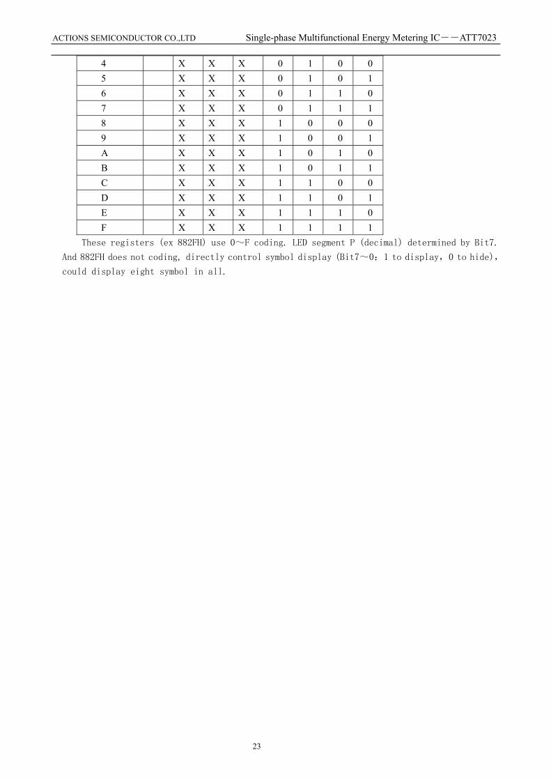
•8828H~882FH --- LED display data buffer Write Only 8828H Display bit 1 data 8829H Display bit 2 data 882AH Display bit 3 data 882BH Display bit 4 data 882CH Display bit 5 data 882DH Display bit 6 data 882EH Display bit 7 data 882FH P G F E D C B A
Data in register LED display
Bit7 Bit6 Bit5 Bit4 Bit3 Bit2 Bit1 Bit00 X X X 0 0 0 0 1 X X X 0 0 0 1 2 X X X 0 0 1 0 3 X X X 0 0 1 1
ACTIONS SEMICONDUCTOR CO.,LTD Single-phase Multifunctional Energy Metering IC――ATT7023
23
4 X X X 0 1 0 0 5 X X X 0 1 0 1 6 X X X 0 1 1 0 7 X X X 0 1 1 1 8 X X X 1 0 0 0 9 X X X 1 0 0 1 A X X X 1 0 1 0 B X X X 1 0 1 1 C X X X 1 1 0 0 D X X X 1 1 0 1 E X X X 1 1 1 0 F X X X 1 1 1 1
These registers (ex 882FH) use 0~F coding. LED segment P (decimal) determined by Bit7.
And 882FH does not coding, directly control symbol display (Bit7~0:1 to display,0 to hide),
could display eight symbol in all.

ACTIONS SEMICONDUCTOR CO.,LTD Single-phase Multifunctional Energy Metering IC――ATT7023
24
Chapter 6 UART FUNCTION §6.1 UART function introduce
The ATT7023 have two hardware universal asynchronous full- duplex receive transmit (UART0
and UART1) peripheral module that is used for serial data communication. The UART0 is built in
the 8051, UART1 is substantive ectad the 8051.
In the UART1 module, the FIFO is data buffer that could be put into 8-bytes data. The
communication protocol includes one start bit, 5-8 data bit, one odd-even parity bit, and 1-2
stop bit. The baud rate of UART1 could up to 1.5MB/s. The LSB is exported firstly when transmits.
The ATT7023 have 38KHz pulse output for infrared modulated wave which from 6MHz, which could
cooperate with TX1 output of UART1, which control by 883AH[Bit6] (SharpIRDis).
§6.2 Programmed
Before use UART1 to transmit data, aptotic protocol (baud, bit number, odd-even parity ect)
must be intercalated.
The needed recourse:
1、 interrupt control/status register:8844H,8846H;
2、 UART1 baud rate select register:8838H,8839H;
3、 UART1 control/FIFO data/status register:883AH, 883BH, 883CH.
Working approach:
1、 Enact the correlative bit of interrupt priority SFR (IP) and enable SFR (IE) in 8051. 2、 Enact baud rate: write correct data to 8838H and 8839H. 3、 Enact the correlative bit of 883AH and 883CH. 4、 Enable UART1: set the interrupt control register 8846H[bit4]. 5、 When transmits, write data to 883BH, the 883CH[bit4] would be set when transmit complete. 6、 When receive, the 883CH[bit5] would be set when one frame data receive complete.
§6.3 UART register •8838H --- UART1 baud rate select register low byte Read/Write
8 位 BDCoe7 BDCoe6 BDCoe5 BDCoe4 BDCoe3 BDCoe2 BDCoe1 BDCoe0
Reset 0 0 0 0 0 0 0 0
The timing circuitry comes into being the baud rate of UART1, which could be adjusted by software.
For example, if the baud is 1200bps, these registers should be write: 6000000/(1200×8)=625.
•8839H --- UART1 baud rate select register high byte Read/Write
8 位 BDCoe15 BDCoe14 BDCoe13 BDCoe12 BDCoe11 BDCoe10 BDCoe9 BDCoe8
Reset 0 0 0 0 0 0 0 0
•883AH --- UART1 control register Read/Write (8 位) TIE RIE STKP EPS PEN SharpIRDis WL1 WL0
Reset 0 0 0 0 0 0 0 0
Bit 7: UART2 TX IRQ enabled

ACTIONS SEMICONDUCTOR CO.,LTD Single-phase Multifunctional Energy Metering IC――ATT7023
25
Bit 6: UART2 RX IRQ enabled Note:Disable UART2 clock when both TIE and RIE are zero.
Bit 5: STKP, Stick parity Bit 4: EPS, Even parity Bit 3: PEN, Parity enable
PEN EPS STKP Selected Parity 0 x x None 1 0 0 Odd 1 1 0 Even 1 0 1 logic 1 1 1 1 logic 0
Bit 2: SharpIRDis =0, TX2 Output modulated by IR 38K pulse. =1, TX2 Output haven’t modulated by IR 38K pulse. Bit 1~0: WL[1:0], bits per transmission
WL1 0 Bit per transmission 0 0 5 bits 0 1 6 bits 1 0 7 bits 1 1 8 bits
•883BH --- UART1 FIFO DATA register Read/Write
DATA7 DATA6 DATA5 DATA4 DATA3 DATA2 DATA1 DATA0
Reset X X X X X X X X
UART FIFO Data, write to this port will write data to UART2 TX FIFO, read from this port will read data from UART2 RX FIFO. •883CH --- UART1\FIFO status register Read/Write
R_ERR IRQMD R_IRQ T_IRQ RFIFOE TFIFOF RFIFOERR TFIFOERR
Reset 0 0 0 0 1 0 0 0
Bit 7: UART2 receive error, 0 receive OK, 1 receive error occurs. Write 1 to this bit will clear the bit, otherwise the bit is unchanged.
Bit 6: UART2 FIFO mode control 0 issue IRQ when vacancy in TX FIFO or at least 1 data in RX FIFO 1 issue IRQ when TX FIFO is half empty or RX FIFO is half full
Bit 5: UART2 RX IRQ is pending, write 1 to the bit to clear it. Write 0 to the bit, unchanged. Bit 4: UART2 TX IRQ is pending, write 1 to the bit to clear it. Write 0 to the bit, unchanged. Bit 3: UART2 RX FIFO EMPTY, read only Bit 2: UART2 TX FIFO FULL, read only Bit 1: RX FIFO error, write 1 to this bit will clear the bit and reset the FIFO. Bit 0: TX FIFO error, write 1 to this bit will clear the bit and reset the FIFO.

ACTIONS SEMICONDUCTOR CO.,LTD Single-phase Multifunctional Energy Metering IC――ATT7023
26
Chapter 7 SPI FUNCTION §7.1 SPI function introduce
The ATT7023 have one hardware universal synchronous receive transmit peripheral module that
is used for serial data communication. The SPI have no error parity, use 4 PIN: SPIDO,SPIDI,
SPICK,SPICS.
The SPI is disabling when SPICS is logic high. When SPICS is active logic low, the SPI could
transmit data basing on SPICK. A frame consists of 32 bits, the first 8 bits is command and the
rest is data. The MSB is transmitted firstly.
Frame format:
Bit 0: =0, SPI transmit data to exterior
=1, SPI receive data from exterior
Bit 1~7: command Bit 8~31: Data
SPI working process: (When SPICS is logic low, the SPI write command to 8033H automatically)
1) ATT7023 receive: When SPICS is logic low and SPICK have clock input, the SPI start
receive data. Command format: ‘1xxxxxxx’. The interrupt bring when one frame data
transmission complete. Heretofore, the SPI has already write command and data to
corresponding register (8830H – 8833H).
2) ATT7023 transmit: When SPICS is logic low and SPICK have clock input, the SPI start
receive data. Command format: ‘0xxxxxxx’. The SPI bring a interrupt to 8051 after
received 8-bit command data. By a period of time (Tmid), the SPI start transmit the
data of corresponding register (8830H – 8832H).
Timing:
SPICS
SPICK
SPIDO
SPIDI
Tmid
When the ATT7023 receive, Tmid= clk/2. When the ATT7023 transmit, Tmid bases on the disposal
rate of 8051: respond the interrupt, write needed data to SPI data buffer.
§7.2 Programmed
1、 Define the transport protocols. 2、 Enact the terminal control register, enable SPI interrupt (include the INT0 enable of
8051 and 8846H).
3、 Check-up the SPI command register and respond interrupt when SPI interrupt occurred. 4、 Clear the interrupt flag.

ACTIONS SEMICONDUCTOR CO.,LTD Single-phase Multifunctional Energy Metering IC――ATT7023
27
§7.3 SPI register •8830H --- SPI Data Buffer low byte Read/Write
SD7 SD6 SD5 SD4 SD3 SD2 SD1 SD0
Reset X X X X X X X X
•8831H --- SPI Data Buffer middle byte Read/Write
SD15 SD14 SD13 SD12 SD11 SD10 SD9 SD8
Reset X X X X X X X X
•8832H --- SPI Data Buffer high byte Read/Write
SD23 SD22 SD21 SD20 SD19 SD18 SD17 SD16
Reset X X X X X X X X
•8833H --- SPI command register Read Only
COM7 COM6 COM5 COM4 COM3 COM2 COM1 COM0
Reset 0 0 0 0 0 0 0 0
COM7:(read or write) =0, SPI transmit data to exterior
=1, SPI receive data from exterior
COM6~COM0: command format determined by software.

ACTIONS SEMICONDUCTOR CO.,LTD Single-phase Multifunctional Energy Metering IC――ATT7023
28
Chapter 8 POWER MANAGE §8.1 Power manage introduce
The ATT7023 contains an on-chip power supply monitor. The analog supply (AVCC) is continuously
monitored by the ATT7023. If the supply is less than 4.1V±5%, the ATT7023 would come into being
an internal interrupt signal which as INT0 input for 8051, that will result in the power fail
interrupt.
The ATT7023 will enter into standby mode when power cut. In standby mode, the ATT7023 should
be power supplied by mothball battery and is activable from external signal(come from SBSW_ PIN).
After activated, the ATT7023 enter into idle mode.
§8.2 Standby mode characteristic
① Standby SRAM (256byte) retention;
② Measure block is power cut;
③ RTC module retention. The lowest working voltage is 3.0V and typical is 3.5V.
④ The power supply of other circuitry is shut off.
⑤ The 8051 could be activated by external signal form SBSW_ PIN.
⑥ The power consumption of integrated circuitry is lower to 5uA.
§8.3 Idle mode characteristic
① The 8051 and correlative RAM/ROM resume power supply by mothball battery;
② The LCD could display when display mode is LCD;
③ Measure block, SPI and UART is power cut;
④ Come back to standby mode which decided by software;
⑤ The signal from SBSW_ PIN is invalid;
⑥ The power consumption of integrated circuitry is lower to 40uA.
ACTIONS SEMICONDUCTOR CO.,LTD Single-phase Multifunctional Energy Metering IC――ATT7023
29
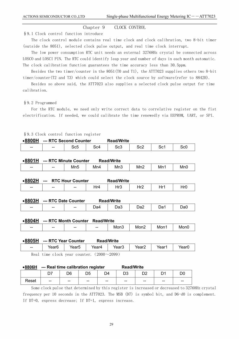
Chapter 9 CLOCK CONTROL §9.1 Clock control function introduce
The clock control module contains real time clock and clock calibration, two 8-bit timer
(outside the 8051), selected clock pulse output, and real time clock interrupt.
The low power consumption RTC unit needs an external 32768Hz crystal be connected across
LOSCO and LOSCI PIN. The RTC could identify leap year and number of days in each month automatic.
The clock calibration function guarantees the time accuracy less than 30.5ppm.
Besides the two timer/counter in the 8051(T0 and T1), the ATT7023 supplies others two 8-bit
timer/counter(T2 and T3) which could select the clock source by software(refer to 8842H).
Besides so above said, the ATT7023 also supplies a selected clock pulse output for time
calibration.
§9.2 Programmed
For the RTC module, we need only write correct data to correlative register on the fist
electrification. If needed, we could calibrate the time renewedly via EEPROM, UART, or SPI.
§9.3 Clock control function register •8800H --- RTC Second Counter Read/Write
-- -- Sc5 Sc4 Sc3 Sc2 Sc1 Sc0
•8801H --- RTC Minute Counter Read/Write
-- -- Mn5 Mn4 Mn3 Mn2 Mn1 Mn0
•8802H --- RTC Hour Counter Read/Write
-- -- -- Hr4 Hr3 Hr2 Hr1 Hr0
•8803H --- RTC Date Counter Read/Write
-- -- -- Da4 Da3 Da2 Da1 Da0
•8804H --- RTC Month Counter Read/Write
-- -- -- -- Mon3 Mon2 Mon1 Mon0
•8805H --- RTC Year Counter Read/Write
-- Year6 Year5 Year4 Year3 Year2 Year1 Year0
Real time clock year counter.(2000~2099)
•8806H --- Real time calibration register Read/Write
D7 D6 D5 D4 D3 D2 D1 D0
Reset -- -- -- -- -- -- -- --
Some clock pulse that determined by this register is increased or decreased to 32768Hz crystal
frequency per 10 seconds in the ATT7023. The MSB (D7) is symbol bit, and D6-d0 is complement.
If D7=0, express decrease; If D7=1, express increase.

ACTIONS SEMICONDUCTOR CO.,LTD Single-phase Multifunctional Energy Metering IC――ATT7023
30
•8809H --- RTC interrupt interval select register Read/Write
---- ---- ---- ---- ---- ---- RTC1 RTC0
Reset X X X X X X 0 0
Determine the interval of RTC interrupt (IRQ13).
RTC1, 0 = 00,1 second;
= 01,1 minute;
= 10,1 hour;
= 11,1 day.
•8840H --- 8 bit Timer2 Reload Data Write Only
STA7 STA6 STA5 STA4 STA3 STA2 STA1 STA0
Reset 0 0 0 0 0 0 0 0
This is an 8-bit count down counter。When counter reaches zero,IRQ occurs,and counter reload
this data and continue counting until this timer is disabled。The period between 2 contiguous
IRQ is: ∆T=(Data+1)/(Clock Source).
•8841H --- 8 bit Timer3 Reload Data Write Only
STB7 STB6 STB5 STB4 STB3 STB2 STB1 STB0
Reset 0 0 0 0 0 0 0 0
This is a countdown timer,when written a data after enable IRQ7,it starts the countdown
procedure;when counts to 0,it stops and IRQ7 occurs. It will be disabled when IRQ7 is disabled.
Total T= (data +1) / (Clock Source).
•8842H --- Timer/counter control register Write Only
TSS31 TSS30 TSS21 TSS20 ITS11 ITS10 ITS01 ITS00
Reset 0 0 0 0 0 0 0 0
TSS31 TSS30 Timer3 Clock source
0 0 4Hz
0 1 64Hz
1 0 32768Hz
1 1 8051 frequency
TSS21 TSS20 Timer2 Clock source
0 0 4Hz
0 1 64Hz
1 0 32768Hz
1 1 8051 frequency
ITS11 ITS10 Timer1 Clock source
0 0 8051Pin T1 connect 4Hz
0 1 8051Pin T1 connect 64Hz
1 0 8051Pin T1 connect 32768Hz
1 1 T1 connect 8051 frequency/8

ACTIONS SEMICONDUCTOR CO.,LTD Single-phase Multifunctional Energy Metering IC――ATT7023
31
ITS01 ITS00 Timer0 Clock source
0 0 8051Pin T0 connect 4Hz
0 1 8051Pin T0 connect 64Hz
1 0 8051Pin T0 connect 32768Hz
1 1 T1 connect 8051 frequency/8
•8849H --- Watch Dog Timer control/ Time pulse control register -- WDT1 WDT0 -- -- T2 T1 T0
Reset -- 0 0 -- -- 0 0 0
Read this register would clear watchdog timer.
WDT[1-0]:Watch dog timer select --------Write Only
WDT [1-0] watchdog length
0 0 62.5 ms
0 1 125 ms
1 0 250 ms
1 1 2 s
T[2-0]: control the output frequency of TO pin.
T2 T1 T0 (TO PIN output frequency) --------Write Only 0 0 0 1Hz pulse output——(1S)
0 0 1 2Hz pulse output——(0.5S) 0 1 0 4Hz pulse output——(0.25S) 0 1 1 8Hz pulse output——(0.125S) 1 0 0 32Hz pulse output——(31.25ms) 1 0 1 128Hz pulse output 1 1 0 1024Hz pulse output 1 1 1 32768Hz pulse output (clock calibration)

ACTIONS SEMICONDUCTOR CO.,LTD Single-phase Multifunctional Energy Metering IC――ATT7023
32
Chapter 10 IC ENCAPSULATION

ACTIONS SEMICONDUCTOR CO.,LTD Single-phase Multifunctional Energy Metering IC――ATT7023
33
APPENDIX:CORRELATIVE DATUM ABOUT 8051
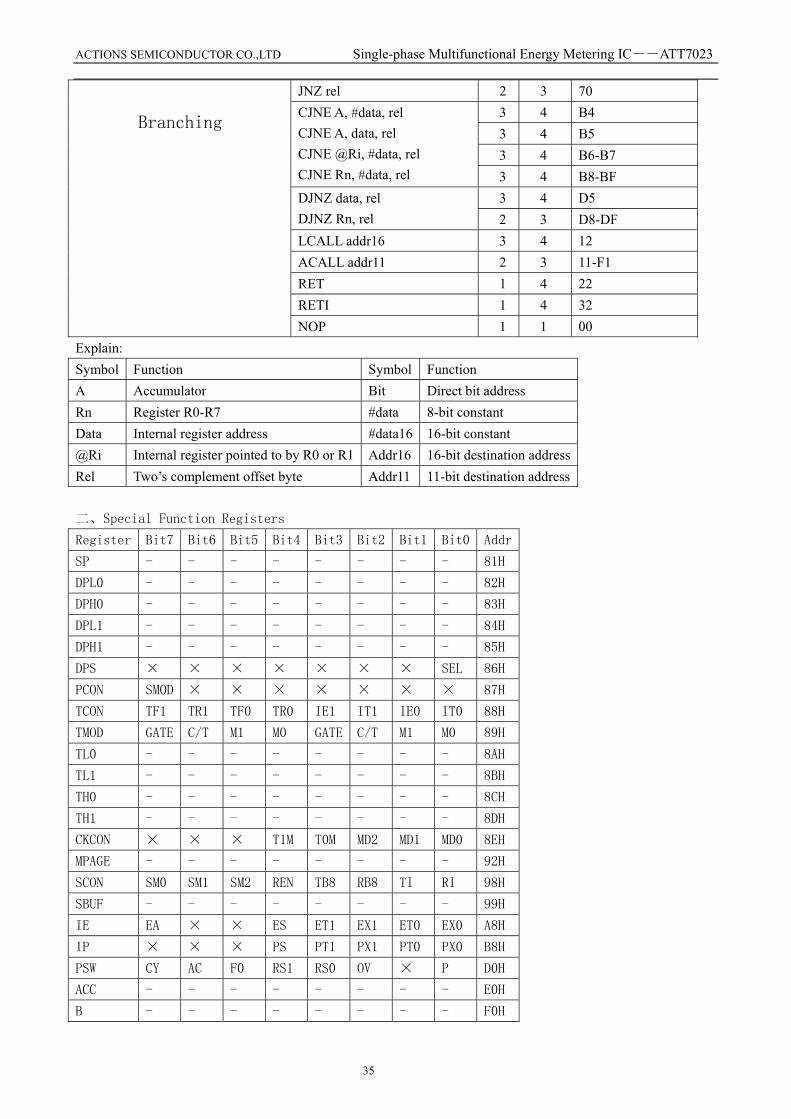
一、Instruction Set
Instruction style Mnemonic Byte Instr.
Cycles Hex Code
2 2 74 3 3 75 2 2 76-77
MOV A, #data MOV data, #data MOV @Ri, #data MOV Rn, #data 2 2 78-7F
2 2 E5 1 1 E6-E7 1 1 E8-EF 2 2 F5 1 1 F6-F7
MOV A, data MOV A, @Ri MOV A, Rn MOV data, A MOV @Ri, A MOV Rn, A 1 1 F8-FF
3 3 85 2 2 86-87 2 2 8-8F 2 2 A6-A7
MOV data, data MOV data, @Ri MOV data, Rn MOV @Ri, data MOV Rn, data 2 2 A8-AF MOV DPTR, #data16 3 3 90 MOVX A, @DPTR 1 2-9 E0 MOVX A, @Ri 1 2-9 E2-E3 MOVX @DPTR, A 1 2-9 F0 MOVX @Ri, A 1 2-9 F2-F3 MOVC A, @A+PC 1 3 83
MOVC A, @A+DPTR 1 3 93 XCH A, data 2 2 C5 XCH A, @Ri 1 1 C6-C7 XCH A, Rn 1 1 C8-CF XCHD A, @Ri 1 1 D6-D7 PUSH data 2 2 C0
Data Transfer
POP data 2 2 D0 1 1 E4 CLR A
CPL A 1 1 F4 1 1 23 1 1 33 1 1 03 1 1 13
RL A RLC A RR A RRC A SWAP A 1 1 C4
2 2 54(44,64) 2 2 55(45,65) 1 1 56-57(46-47,66-67)
Logical
ANL(ORL, XRL) A, #data ANL(ORL, XRL) A, data ANL(ORL, XRL) A, @Ri ANL(ORL, XRL) A, Rn 1 1 58-5F(48-4F,68-6F)

ACTIONS SEMICONDUCTOR CO.,LTD Single-phase Multifunctional Energy Metering IC――ATT7023
34
2 2 52(42,62) ANL(ORL, XRL) data, A ANL(ORL, XRL) data, #data 3 3 53(43,63)
2 2 24 2 2 25 1 1 26-27
ADD A, #data ADD A, data ADD A, @Ri ADD A, Rn 1 1 28-2F
2 2 34 2 2 35 1 1 36-37
ADDC A, #data ADDC A, data ADDC A, @Ri ADDC A, Rn 1 1 38-3F
2 2 94 2 2 95 1 1 96-97
SUBB A, #data SUBB A, data SUBB A, @Ri SUBB A, Rn 1 1 98-9F MUL AB 1 5 A4 DIV AB 1 5 84 INC(DEC) A 1 1 04(14) INC(DEC) data 2 2 05(15) INC(DEC) @Ri 1 1 06-07(16-17) INC(DEC) Rn 1 1 08-0F(18-1F) INC DPTR 1 3 A3
Arithmetic
DA A 1 1 D4 MOV C, bit 2 2 A2 MOV bit, C 2 2 92
2 2 C2 CLR bit CLR C 1 1 C3
2 2 B2 CPL bit CPL C 1 1 B3
2 2 D2 SETB bit SETB C 1 1 D3 ANL C, bit 2 2 82 ANL C, /bit 2 2 B0 ORL C, bit 2 2 72 ORL C, /bit 2 2 A0 JC rel 2 3 40 JNC rel 2 3 50 JB bit, rel 3 4 20 JNB bit, rel 3 4 30
Boolean
JBC bit, rel 3 4 10 LJMP addr16 3 4 02 AJMP addr11 2 3 01-E1 SJMP rel 2 3 80 JMP @A+DPTR 1 3 73
JZ rel 2 3 60
ACTIONS SEMICONDUCTOR CO.,LTD Single-phase Multifunctional Energy Metering IC――ATT7023
35
JNZ rel 2 3 70 3 4 B4 3 4 B5 3 4 B6-B7
CJNE A, #data, rel CJNE A, data, rel CJNE @Ri, #data, rel CJNE Rn, #data, rel 3 4 B8-BF
3 4 D5 DJNZ data, rel DJNZ Rn, rel 2 3 D8-DF LCALL addr16 3 4 12 ACALL addr11 2 3 11-F1 RET 1 4 22 RETI 1 4 32
Branching
NOP 1 1 00 Explain: Symbol Function Symbol Function A Accumulator Bit Direct bit address Rn Register R0-R7 #data 8-bit constant Data Internal register address #data16 16-bit constant @Ri Internal register pointed to by R0 or R1 Addr16 16-bit destination address Rel Two’s complement offset byte Addr11 11-bit destination address 二、Special Function Registers
Register Bit7 Bit6 Bit5 Bit4 Bit3 Bit2 Bit1 Bit0 Addr
SP - - - - - - - - 81H
DPL0 - - - - - - - - 82H
DPH0 - - - - - - - - 83H
DPL1 - - - - - - - - 84H
DPH1 - - - - - - - - 85H
DPS × × × × × × × SEL 86H
PCON SMOD × × × × × × × 87H
TCON TF1 TR1 TF0 TR0 IE1 IT1 IE0 IT0 88H
TMOD GATE C/T M1 M0 GATE C/T M1 M0 89H
TL0 - - - - - - - - 8AH
TL1 - - - - - - - - 8BH
TH0 - - - - - - - - 8CH
TH1 - - - - - - - - 8DH
CKCON × × × T1M T0M MD2 MD1 MD0 8EH
MPAGE - - - - - - - - 92H
SCON SM0 SM1 SM2 REN TB8 RB8 TI RI 98H
SBUF - - - - - - - - 99H
IE EA × × ES ET1 EX1 ET0 EX0 A8H
IP × × × PS PT1 PX1 PT0 PX0 B8H
PSW CY AC F0 RS1 RS0 OV × P D0H
ACC - - - - - - - - E0H
B - - - - - - - - F0H
ACTIONS SEMICONDUCTOR CO.,LTD Single-phase Multifunctional Energy Metering IC――ATT7023
36
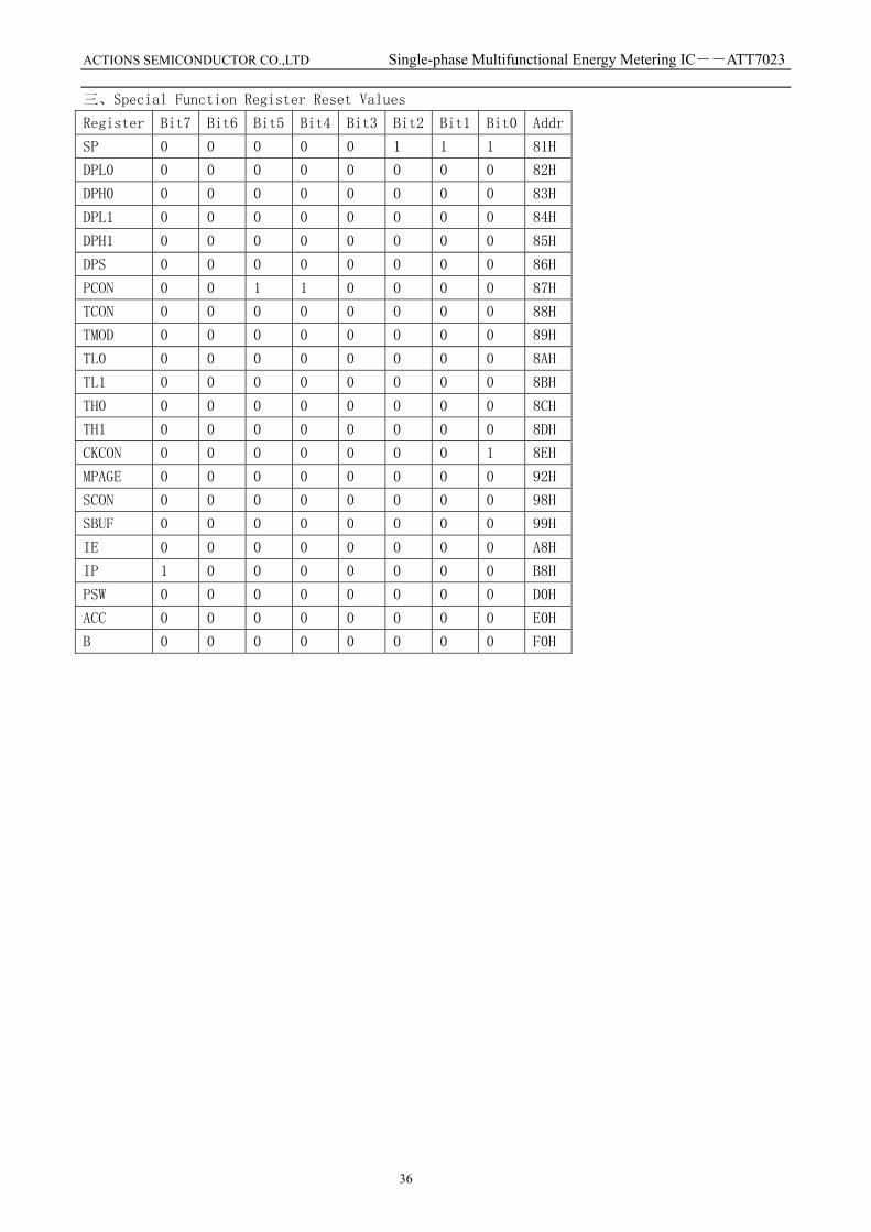
三、Special Function Register Reset Values
Register Bit7 Bit6 Bit5 Bit4 Bit3 Bit2 Bit1 Bit0 Addr
SP 0 0 0 0 0 1 1 1 81H
DPL0 0 0 0 0 0 0 0 0 82H
DPH0 0 0 0 0 0 0 0 0 83H
DPL1 0 0 0 0 0 0 0 0 84H
DPH1 0 0 0 0 0 0 0 0 85H
DPS 0 0 0 0 0 0 0 0 86H
PCON 0 0 1 1 0 0 0 0 87H
TCON 0 0 0 0 0 0 0 0 88H
TMOD 0 0 0 0 0 0 0 0 89H
TL0 0 0 0 0 0 0 0 0 8AH
TL1 0 0 0 0 0 0 0 0 8BH
TH0 0 0 0 0 0 0 0 0 8CH
TH1 0 0 0 0 0 0 0 0 8DH
CKCON 0 0 0 0 0 0 0 1 8EH
MPAGE 0 0 0 0 0 0 0 0 92H
SCON 0 0 0 0 0 0 0 0 98H
SBUF 0 0 0 0 0 0 0 0 99H
IE 0 0 0 0 0 0 0 0 A8H
IP 1 0 0 0 0 0 0 0 B8H
PSW 0 0 0 0 0 0 0 0 D0H
ACC 0 0 0 0 0 0 0 0 E0H
B 0 0 0 0 0 0 0 0 F0H