attachment 8 containers - michigan · 2016-02-26 · pallets. storage of the containers on pallets...
TRANSCRIPT
US ECOLOGY MICHIGAN MID 074 259 565
ATTACHMENT 8
CONTAINERS
GLOSSARY
Effective April 22, 2019, the Michigan Department of Environmental Quality (DEQ), Waste Management and Radiological Protection Division (WMRPD), became the Michigan Department of Environment, Great Lakes, and Energy (EGLE), Materials Management Division (MMD). 40 CFR Title 40 of the Code of Federal Regulations ABR Adopted by reference Act 207 Michigan Fire Protection Act, PA 207, as amended Act 451 Natural Resources and Environmental Protection Act,
1994 PA 451, as amended Dynecol former name of facility, now known as US Ecology Detroit North, Inc US Ecology Michigan? EPA United States Environmental Protection Agency HWSA Hazardous and Solid Waste Amendments of 1984 Part 111 Part 111, Hazardous Waste Management, of Act 451 Part 111 Rules Administrative rules promulgated pursuant to Part 111, Hazardous
Waste Management, of Act 451 R Rule (example: R 299.9504)
Use and Management of Containers, Revision 2/28/13 EPA ID No. MI D074259565
Page 1 of 13 Form EQP5111 Attachment Module C1 (04/03/02)
FORM EQP5111 ATTACHMENT TEMPLATE MODULE C1
USE AND MANAGEMENT OF CONTAINERS
The Administrative Rules for Part 111, Hazardous Waste Management, of the Michigan Natural Resources and Environmental Protection Act, 1994 PA 451, as amended (Act 451) Rule 299.9614 of the Part 111 Rules; R 29.4101 to R 29.4505 pursuant to the provisions of the Michigan Fire Protection Act, PA 207, as amended (Act 207); and Title 40 Code of Federal Regulations (40 CFR) 270.14(d), 270.15, and Part 264, Subpart I, which are adopted by reference (ABR) in R 299.11003, establish requirements for the use and management of containers. This license application module addresses requirements for the use and management of containers at Dynecol, Inc. in Detroit, Michigan. This module addresses the condition of containers, compatibility of waste with containers, management of containers, inspections, containment, special requirements for ignitable or reactive waste, special requirements for incompatible wastes, and closure. (Check as appropriate) Operating License Applicant:
R 299.9614 Use and Management of Containers Construction Permit Applicant: R 299.9614 Use and Management of Containers
More than one box may be checked, if the facility has an existing container storage area and will construct a new container storage area.
This module is organized as follows: C1.A Description of Containers C1.B Condition of Containers C1.C Compatibility of Waste with Containers C1.D Management of Containers C1.E Inspections C1.F Containment
C1.F (1) Secondary Containment System Design and Operation for Containers with Free Liquids

Use and Management of Containers, Revision 2/28/13 EPA ID No. MI D074259565
Page 2 of 13 Form EQP5111 Attachment Module C1 (04/03/02)
C1.F (1)(a) Requirement for Base or Liner C1.F (1)(b) Containment System Drainage C1.F (1)(c) Containment System Capacity C1.F (1)(d) Control of Run-on C1.F (1)(e) Removal of Liquids from Containment System
C1.F (2) Secondary Containment System Design and Operation for Containers
with No Free Liquids
C1.F (2)(a) Containment System Drainage C1.F (2)(b) Container Management
C1.G Special Requirements of Ignitable or Reactive Waste C1.H Special Requirements for Incompatible Wastes C1.I Closure
Use and Management of Containers, Revision 2/28/13 EPA ID No. MI D074259565
Page 3 of 13 Form EQP5111 Attachment Module C1 (04/03/02)
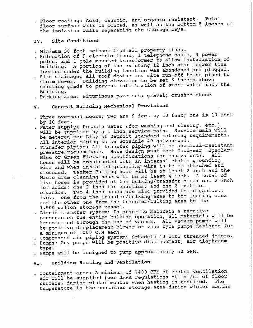
C1.A DESCRIPTION OF CONTAINERS {R 299.9614 and 40 CFR 264.171, which is ABR in R299.11003} Dynecol, Inc. stores containers of hazardous waste in a facility which is specifically designed for this type of hazardous waste storage. The containers that are stored in the facility are of various sizes up to and including large volume totes. The waste is temporarily stored within the facility until they are transferred for off-site treatment and/or disposal or on-site treatment. The primary containment devices that are used to store hazardous wastes in the storage facility are 500-gallon totes, 55-gallon drums, or smaller containers as appropriate. Containerized hazardous wastes that are received by Dynecol may be consolidated by compatibility. The contents of any container that is in unsatisfactory condition or incompatible with the container are promptly placed in a compatible container in good condition. CONTAINER MANAGEMENT FACILITY The hazardous waste CMF is centrally located area to the east of the bulk treatment facility and has a minimum 50 foot set back from all property lines (refer to Figure A1-4). The 95-foot by 122-foot structure is designed to meet all applicable BOCA, NFPA, and NEC codes for storage of flammable liquid wastes (Class I, II, III liquids). All concrete walls are rated for four-hour fire protection. The service and garage doors are three-hour fire rated. Access to the building is limited to vehicles at the loading docks within the southeastern corner of the structure and the garage door at the south corner of the building, and to pedestrians at four locations along the north, southeast, and south sides of the facility. The interior areas of the building are heated between 50 and 60 degrees F in the winter with 7400 cfm of air flow per NFPA standards, and are cooled by ventilation fan in the summer with an increased air flow of 10,000 cfm. The CMF consists of two loading docks, eight isolation storage bays, a waste bulking and transfer area, and a drum washing bay. The 32-foot by 60-foot loading/unloading area located in the southeastern corner of the facility is roofed but without side walls. Wall skirting is provided as a barrier against precipitation infiltration. Spill containment is provided in this area to contain any spills or leaks. The floor coating is acid-, caustic-, and organic-resistant in the containment area as well as in the required section of the truck well area. The loading docks are equipped with truck bumpers, mechanical levelers, and an access ladder. The CMF consists of eight, 19-foot by 21.5-foot isolation bays constructed from poured concrete designed to provide for the separate storage of incompatible or reactive wastes (see Drawing A.1 of Appendix C1-2). Each bay holds up to 120 drums (6,600 gallons) of a maximum of two levels of pallets. Storage of the containers on pallets facilitates inspection of the container storage area for leaks. Aisle space is provided to facilitate the unobstructed movement of personnel, fire protection equipment, and spill control/decontamination equipment to any area of the facility operation during and emergency. Containers with flammable wastes are placed no further than 12 feet from the main aisle. Each bay is constructed to contain a spill or leak of approximately 1,221 gallons (more than 10% of maximum stored volume). Each bay contains a blind sump that can be used to remove spilled wastes from the bay. The total floor surface area in each bay is constructed of concrete with a continuous chemical-resistant coating including the bottom eight inches of the walls separating the storage bays. The bay divider walls are six feet high to inhibit any releases from containers stored on the second level of pallets from exiting the storage bay.

Use and Management of Containers, Revision 2/28/13 EPA ID No. MI D074259565
Page 4 of 13 Form EQP5111 Attachment Module C1 (04/03/02)
The waste bulking and transfer area is used to consolidate small quantities of certain compatible wastes into containers and to bulk any containerized wastes into bulk tankers for transport off-site or treatment on site. The bulking/transfer area and the drum washing bay are equipped with fume hoods which are connected to an air emission control system consisting of a blower (a minimum of 1,000 cfm), two activate carbon vessels (a minimum of 1,800 pounds of carbon each), and a 5,000 cfm caustic scrubber. The bulking/transfer area is coated with a continuous chemical-resistant coating and connected to a blind sump for collecting any spills. Transfer of materials from the bulking/transfer area to the tanker truck is achieved through one of three separate hoses with appropriate couplings; one each for acids, alkalines, and organics. Ventilation air within the bulking/transfer area is supplied at a rate of a minimum of 1,000 cfm whenever bulking is performed. There are no stored containers in this area. All electrical components within the container storage area are explosion-proof. A grounding system is installed in the bulking and transfer area to allow containers to be grounded during transfer operations. Electrical service lines and conduits are routed overhead with no conduits or wiring penetrating the walls of the storage bays. A separate room (the mechanical room) for the facility’s controls is isolated from any potential explosion area since the equipment in this room is not explosion-proof. Compressed air piping is a schedule 40 galvanized system with threaded joints and is supplied by an existing compressor in another on-site building. Potable water supply to the storage facility is provided through a service main, metered according to the City of Detroit standard metering requirements. Interior water piping is schedule 40 galvanized steel pipe. Fire protection water supply to the sprinkler system is from an eight-inch water main. Below-grade piping is ductile iron while above-grade piping is schedule 40 galvanized steel. The fire protection for Bay #1 is a dry chemical system with standard heat detection and six 50 pound dry chemical cylinders. The storage area and loading dock area is provided with a closed head foam/water sprinkler system proportioned at 3% or 16 gallons design rate based on a maximum of 2000 square feet for a 15 minute run time with a bladder tank. Short-term parking for vehicles that load or unload hazardous waste containers into or out of the storage facility is provided adjacent to the storage facility. All roof drains and site runoff are piped to storm sewers. The adjacent concrete areas to the building are sloped away from the building to direct drainage towards the site storm sewers. BUILDING 4 Building 4 is located on the west side of Dynecol’s Treatment Facility. The proposed hazardous waste storage and treatment will be conducted in an enclosed 20,250 square foot building within three in-ground concrete steel lined stabilization/processing pits totaling approximately 90,000 gallons. The process pits are constructed of 24-inch thick reinforced concrete with a ¾-inch plate steel liner. Spill containment is provided in this area to contain any spills or leaks. The floor coating is acid-, caustic- and organic-resistant in the containment area as well as in the required section of the truck well area. See Appendix C1-6 for general layout and drawings for Building 4. The pits receive liquid and solid wastes from bulk tankers and containers. Mixing within the pits, if required, is accomplished by mechanical means and is placed into dump trailers/roll off boxes for

Use and Management of Containers, Revision 2/28/13 EPA ID No. MI D074259565
Page 5 of 13 Form EQP5111 Attachment Module C1 (04/03/02)
storage and/or transport to the final disposal facility. Building 4 will have a container staging area that will receive, transfer, and store hazardous and non-hazardous wastes in containers of various sizes up to 500 gallons in capacity. In additional there is a bulk container staging area that will store hazardous wastes. The maximum number of drums containing waste material that may be stored in this building is 1,120. This capacity was calculated assuming that the drums will be staged on pallets, 4 feet by 4 feet (16 square feet area). Eight total drums are stored on each pallet (4 drums stacked 2 drums high) in the container storage area which is approximately 70 feet by 32 feet (2,240 square feet area) on the northwest side of the building. Several different waste types may be stored in the same area based on the Compatibility Matrix. Incompatible wastes are segregated in accordance with Table A3-3 in separate storage areas. PROPOSED BUILDING 5A The proposed Building 5A will be located adjoining east of Building 4. The proposed Building 5A will be used for the storage, bulking and consolidation of wastes. The storing, bulking and consolidation of wastes will be conducted in an enclosed approximately 20,000 square foot building within three recessed containment areas approximately 30 yards each. Dynecol receives waste in a variety of container sizes, for example, small glass or plastic bottles, pails, drums, totes, boxes and cubic yard sacks. Containerized wastes that are bulked and consolidated are subject to the same compatibility and waste code evaluation as wastes that are handled in other parts of the Treatment Facility. Consolidation of waste will occur once the compatibility is determined prior to bulking operations. See Appendix C1-6 for general layout and drawings for Proposed Building 5A and Building 5B. The maximum number of drums containing waste material that may be stored in this building is 4,160. This capacity was calculated assuming that the drums will be staged on pallets, 4 feet by 4 feet (16 square feet area). Eight total drums are stored on each pallet (4 drums stacked 2 drums high) in the container storage area which is approximately 8,350 square feet in area. Other hazardous wastes may be treated at Dynecol’s Treatment Facility or transferred on-site for storage and/or bulking/consolidation. Several different waste types may be stored in the same area based on the Compatibility Matrix. Incompatible wastes are segregated in accordance with Table A3-3 in separate storage areas. PROPOSED BUILDING 5B The containerized hazardous waste in roll-off boxes or trailers, if needed will be stored in the designated, additional storage area, approximately 6,000 square feet in area. The maximum quantity of roll-off boxes/trailers containing waste material that may be stored in this area is 600 yards. This capacity was calculated assuming that the roll-off boxes will be staged on the concrete floor in ten rows of two each. No bulking, mixing or processing of wastes will be performed in the area. The area will be utilized for storage in closed containers until they are shipped off site to an appropriate disposal, recovery, or recycling facility or transferred to and treated in Dynecol’s treatment facility.
Air Emission Control System

Use and Management of Containers, Revision 2/28/13 EPA ID No. MI D074259565
Page 6 of 13 Form EQP5111 Attachment Module C1 (04/03/02)
Dynecol has installed and operates air control systems for all storage tanks, storage areas, and bulking equipment in compliance with current MDEQ-AQD permits. The permit issued by MDEQ-AQD complies with requirements 40 CFR 264.1050 through 40 CFR 1065. Delivery and Receipt of Materials Hazardous wastes are delivered to the CMF in bulk trailers and containers. Prior to receiving a shipment of hazardous waste, the accompanying manifest and LDR notification (if applicable) are inspected. A sample of bulk shipment is then taken and fingerprinted (see Module A3). The fingerprint process is completed within 24 hours from the time the hazardous waste was off-loaded. The total volume of hazardous waste staged for fingerprinting and/or stored in the CMF, Building 4, Proposed Building 5A and Building 5B will not exceed the permitted capacity of the Facility. C1.B CONDITION OF CONTAINERS {R 299.9614 and 40 CFR 264.171, which is ABR in R299.11003} All containers are inspected for their conditions on a daily basis. If the condition of the container is not in good condition, Dynecol will transfer contents into a new container in good condition using a transfer pump and hose. All containers that are stored within the CMF (95-foot by 122-foot structure) are designed to meet all applicable BOCA, NFPA, and NEC codes for storage of flammable liquid wastes. All drums containing hazardous wastes are clearly and accurately labeled. Following waste bulking operations, the empty containers are generally rinsed, crushed, and taken off-site for disposal or recycling. Rinsates from the container washing process are containerized for proper disposal. For containers holding non-hazardous wastes, a “Non-Hazardous Waste” label is affixed to the container to indicate its contents. In the event that container repackaging is necessary due to container corrosion, damage, or leakage, the hazardous waste from this container will be transferred to a container in good condition. An 85-gallon recovery (overpack) drum may also be used to contain a leaking or potentially leaking drum. C1.C COMPATIBILITY OF WASTE WITH CONTAINERS {R.299.9614 and 40 CFR 264.172, which is ABR in R299.11003} Many containerized wastes which may be potentially stored at Dynecol are considered incompatible with each other and must be properly segregated during storage to minimize or eliminate the potential release of toxic gases, explosion, or fire. Dynecol adheres to the segregation scheme as described below to maintain proper segregation of containerized wastes stored in the container management facility. All containers are typically constructed of steel, fiberboard and/or plastic. Since the waste characteristics must be fully defined prior to acceptance of a waste, Dynecol’s Waste Approval Form which is completed by the generator is the primary source of waste characterization information. Table A3-2 summarizes the chemical characterization hierarchy that is used by Dynecol for waste identification. Segregation Scheme
Use and Management of Containers, Revision 2/28/13 EPA ID No. MI D074259565
Page 7 of 13 Form EQP5111 Attachment Module C1 (04/03/02)
Wastes are stored according to the following scheme:
1. Cyanide wastes are define as those wastes containing greater than 250 ppm reactive cyanide and are stored in a separate bay labeled “Poison”. Acid-bearing wastes are not stored within the cyanide bay.
2. Wastes that are characterized as oxidizers per 49 CFR 172.101 are considered
to be oxidizing wastes and will be stored in a bay labeled “Oxidizer”.
3. Waste with a pH less than or equal to two will be stored in a bay labeled “Corrosive Acid”. Wastes having a pH of 12.5 or higher are stored in a bay labeled “Corrosive Base”.
4. Flammable wastes are defined as wastes with flash point less than 100 degrees
F. All flammable wastes are stored in a bay labeled “Flammable Waste”.
5. All wastes which exhibit reactive characteristics with water are stored in a bay labeled “Dangerous When Wet”
6. All other hazardous wastes which are not identified above are stored in a bay
labeled “Hazardous Waste”.
Several different waste types may be stored in the same bay based on the Compatibility Matrix (see Table A3-3). When more than one waste type is stored within the same bay, placards/signs indicating each waste type will be posted. In addition, for ease of managing and checking storage within bays, different wastes types will always be separated by row (different waste types will not be mixed within a row). C1.D MANAGEMENT OF CONTAINERS {R.299.9614 and 40 CFR 264.173, which is ABR in R299.11003} Hazardous containerized wastes destined for storage at Dynecol are properly characterized to ensure that the wastes can be safely stored, and eventually transferred or bulked for outside disposal or on-site treatment. A detailed description of the compatibility testing procedures and characterization scheme is contained in Module A2, Chemical and Physical Analyses. Rejected waste shipments are returned to the generator. Accepted containers are placed in storage where they will remain sealed until they are removed for shipment or bulking, unless unusual circumstances require that the drum be opened again. Containers holding hazardous waste are always closed during storage, except when it is necessary to add or remove waste. Containers will be opened, handled, and stored in such a way that will not rupture the containers or cause them to leak. Those waste shipments that are to be combined and transferred to other containers or are to be bulked into tankers are taken to the waste bulking area. In the event that the transfer is to another container, the newly filled container is appropriately labeled for further processing. Container Management Facility
Use and Management of Containers, Revision 2/28/13 EPA ID No. MI D074259565
Page 8 of 13 Form EQP5111 Attachment Module C1 (04/03/02)
Incompatible and reactive wastes are segregated in accordance with Table A3-3 in separate storage bays. During storage, sufficient aisle space is maintained to provide unobstructed movement of personnel, fire protection equipment, and spill control/decontamination equipment to any area of facility operation during an emergency. Container labels face the aisle and are clearly visible. In order to detect spills or leaks and to prevent the containers from contacting any standing liquids, the containers are stored directly on top of pallets in good condition, stacked no more than two high. In addition, this drum stacking arrangement along with a six-foot high bay dividing wall prevent a punctured drum that has been elevated above the containment structure from overshooting the secondary containment system and contaminating areas outside of the storage bay. The storage bays, waste bulking area, and loading/unloading areas regularly undergo routine inspections to detect any actual releases or any conditions that could result in a release. If the inspection identifies an unsatisfactory condition, such as an actual release or the potential for release, remedial actions as specified in the Contingency Plan (Module A7) will be promptly implemented. Building 4 Incompatible waste in Building 4 will be segregated based on compatibility and management methods. The container storage area of the building has an impervious epoxy coating that is compatible with the types of waste handled by Dynecol. Incoming wastes will be sorted in compatible waste groups as applicable and stored in accordance with the DOT hazard classifications. RCRA-empty containers are generally rinsed and crushed for recycling/disposal. Rinsates from the container washing process are properly managed in accordance with applicable regulations. The container storage areas and containment areas are inspected at least once per day. Containers are stored in a manner that will contain potential leaks/spills within the containment area. Accumulated liquids observed in the containment structure are removed within 24 hours, or in as timely a manner as is possible to prevent harm to human health and the environment. Liquids may be removed by vacuum truck or suitable pumps. Removed liquids are managed properly by the facility or in accordance with applicable regulations Proposed Building 5A The storing, bulking and consolidation of wastes in the Proposed Building 5A will be conducted in an enclosed approximately 20,000 square foot building within four recessed containment areas approximately 30 yards each. Dynecol receives waste in a variety of container sizes, for example, small glass or plastic bottles, pails, drums, totes, boxes and cubic yard sacks. Dynecol may elect to consolidate these containers as a means to more efficiently manage these wastes for further processing or preparation for shipment to the treatment facility or permitted disposal facility. Bulking or consolidation may include the transfer of the smaller containers (e.g. 55-gallon drums) into larger containers such as roll off boxes for shipment to an off-site disposal facility and/or storage. Containerized wastes that are bulked and consolidated are subject to the same compatibility and waste code evaluation as wastes that are handled in other parts of the Treatment Facility. Consolidation of waste will occur once the compatibility is determined prior to bulking operations.

Use and Management of Containers, Revision 2/28/13 EPA ID No. MI D074259565
Page 9 of 13 Form EQP5111 Attachment Module C1 (04/03/02)
The container storage areas and containment areas are inspected at least once per day. Containers are stored in a manner that will contain potential leaks/spills within the containment area. Accumulated liquids observed in the containment structure are removed within 24 hours, or in as timely a manner as is possible to prevent harm to human health and the environment. Liquids may be removed by vacuum truck or suitable pumps. Removed liquids are managed properly by the facility or in accordance with applicable regulations Proposed Building 5B
The containerized hazardous waste in roll-off boxes or trailers, if needed will be stored in the Proposed Building 5B, approximately 6,000 square feet in area. The Proposed Building 5B will be enclosed on three sides with a curb on the fourth side. The maximum number of roll-off boxes/trailers containing waste material that may be stored in this area is 600 yards and roll-off boxes will be staged on the concrete floor in ten rows of two each. No bulking, mixing or processing of wastes will be performed in this area. The area typically will be utilized for storage in closed containers until they are shipped off site to an appropriate disposal, recovery, or recycling facility or transferred to and treated in Dynecol’s treatment facility.
C1.E INSPECTIONS {R.299.9614 and 40 CFR 264.174, which is ABR in R299.11003}
The containment areas are inspected daily to detect any spills or leaks. If any accumulated liquids are detected, they will be promptly sampled, analyzed, characterized, and removed within 24-hours. These liquids will be placed in containers and stored in an appropriate bay for ultimate disposal. Storage of the containers on pallets facilitates inspection of the container storage area for leaks. See Module A5 and Appendix A5-1. C1.F CONTAINMENT {R.299.9614 and 40 CFR 264.175, which is ABR in R299.11003, and 40 CFR
270.15, which is ABR in R299.9504(2)} Container secondary containment information is provided in Section C1.A and Appendices C1-1 and C1-4. C1.F (1) Secondary Containment System Design and Operation for Containers with
Free Liquids {R.299.9614 and 40 CFR 264.175(a), which is ABR in R299.11003 and 40 CFR 270.15(a), which is ABR in R299.9504(2)}
See Appendix C1-1.
C1.F (1)(a) Requirement for Base or Liner
{R.299.9614 and 40 CFR 264.175(b)(1), which is ABR in R299.11003 and 40CFR 270.15(a)(1), which is ABR in R299.9504(2)}
A secondary containment system is provided for each of the eight storage bays, the waste bulking area, and the loading/unloading areas in the hazardous waste CMF. These secondary containment

Use and Management of Containers, Revision 2/28/13 EPA ID No. MI D074259565
Page 10 of 13 Form EQP5111 Attachment Module C1 (04/03/02)
systems are constructed of concrete and are maintained free of cracks or gaps to the extent possible and sufficiently impervious to contain any leaks or spills until the release is detected. The presence and location of cracks (excluding minor cracks or fractures in the surficial coatings), gaps, gouges, chips, spalling etc observed during daily inspections will be documented on inspection records. Minor cracks and fractures are defined as cracks or fractures in the surficial coatings with a width of 1/8” or less. Whenever possible, corrective measures will be implemented on the same day a discrepancy is observed and documented. All floor surfaces, including the secondary containment structures, are covered with a continuous chemical-resistant coating. The coating goes up 8-inches on the bay walls. Secondary containment system in Building 4 are constructed of concrete and are maintained free of cracks or gaps to the extent possible and sufficiently impervious to contain any leaks or spills until the release is detected. The presence and location of cracks (excluding minor cracks or fractures in the surficial coatings), gaps, gouges, chips, spalling etc observed during daily inspections will be documented on inspection records. Minor cracks and fractures are defined as cracks or fractures in the surficial coatings with a width of 1/8” or less. Whenever possible, corrective measures will be implemented on the same day a discrepancy is observed and documented. The storage areas will be covered with a continuous chemical-resistant coating. Secondary containment will be provided for the Proposed Building 5A & Building 5B and the associated loading/unloading areas. These secondary containment systems will be constructed of concrete and will be maintained free of cracks or gaps and will be sufficiently impervious to contain any leaks or spills until the release is detected. All storage areas, including the secondary containment structures, will be covered with a continuous chemical-resistant coating. C1.F (1)(b) Containment System Drainage
{R.299.9614 and 40 CFR 264.175(b)(2), which is ABR in R299.11003 and 40 CFR 270.15(a)(2), which is ABR in R299.9504(2)}
Each of the eight container storage bays measures 19 feet by 21.5 feet and holds no more than 120 - 55-gallon containers. The bays are sloped to drain and remove liquids resulting from any leaks or spills. A blind sump is provided for each storage bay in order to facilitate the removal of spilled or leaked material from the bay. A portable air diaphragm pump can be used, if necessary, to pump out materials in the sumps. Routine inspections of these sumps identify when a release has occurred and appropriate response procedures are then followed in removing this release from the secondary containment system. The waste bulking/transfer area floor is covered with a continuous chemical-resistant coating and is provided with a blind sump for easy removal of spilled or leaked materials. The secondary containment system for the facility’s loading and unloading area consists of a blind sump located in the loading dock. Concrete chemical-resistant floors in this area are sloped toward this sump. The storage areas at Building 4, Proposed Building 5A & Building 5B will be sloped to the drains where applicable; in order to hold prior to removal of any liquids resulting from any leaks or spills. Blind sumps will be provided in order to facilitate the removal of spilled or leaked material from the bays. A portable air diaphragm pump or vacuum truck can be used, if necessary, to pump out materials in the sumps. Inspections per the inspection plan of these sumps identify when a release has occurred and appropriate response procedures will be followed in removing this release from the secondary containment system.

Use and Management of Containers, Revision 2/28/13 EPA ID No. MI D074259565
Page 11 of 13 Form EQP5111 Attachment Module C1 (04/03/02)
The floor in the storage areas will be covered with a continuous chemical-resistant coating for easy removal of spilled or leaked materials. The secondary containment system for the facility’s loading and unloading area consists of a blind sump located in the loading dock. Concrete chemical-resistant floors in this area are sloped toward this sump.
Use and Management of Containers, Revision 2/28/13 EPA ID No. MI D074259565
Page 12 of 13 Form EQP5111 Attachment Module C1 (04/03/02)
C1.F (1)(c) Containment System Capacity {R.299.9614 and 40 CFR 264.175(b)(3), which is ABR in R299.11003 and 40 CFR 270.15(a)(3), which is ABR in R299.9504(2)}
The approximately 1,221-gallon capacity of each storage bay exceeds the requirement for secondary containment to be able to contain 10% of the total maximum volume (6,600 gallons) of waste stored in each bay. The reinforced concrete floor of Building 4 is sloped from the exterior walls towards the center of the building where the process pits are located which would prevent release of material to the environment. The secondary containment at the Proposed Building 5A and the Building 5B will be designed to contain 10% of the total maximum volume. C1.F (1)(d) Control of Run-on
{R.299.9614 and 40 CFR 264.175(b)(4), which is ABR in R299.11003 and 40 CFR 270.15(a)(4), which is ABR in R299.9504(2)}
The approximately 1,221-gallon capacity of each storage bay exceeds the requirement for secondary containment to be able to contain 10% of the total maximum volume (6,600 gallons) of waste stored in each bay. The total floor surface area in each bay is constructed of concrete with a continuous chemical-resistant coating including the bottom eight inches of the walls separating the storage bays. The bay divider walls are six feet high to inhibit any releases from containers stored on the second level from exiting the storage bay. Run-on is prevented from entering the CMF and Building 4 by the roof and walls of the building and by the adjacent concrete areas that are sloped away from the building to direct drainage towards the site storm sewers. Run-on for the Proposed Building 5A and Building 5B will be controlled by enclosure inside a building or enclosed storage structure. The storage area if any exposed to run-off will be inspected daily and pumped out as necessary. C1.F (1)(e) Removal of Liquids from Containment System
{R.299.9614 and 40 CFR 264.175(b)(5), which is ABR in R299.11003 and 40 CFR 270.15(a)(5), which is ABR in R299.9504(2)}
If any accumulated liquids are detected in the bay sumps, they will be promptly sampled, analyzed, characterized, and removed within 24-hours. These liquids will be placed in containers and stored in an appropriate bay for ultimate disposal. Storage of the containers on pallets facilitates inspection of the container storage area for leaks. C1.F (2) Secondary Containment System Design and Operation for Containers with
No Free Liquids {R.299.9614 and 40 CFR 264.175, which is ABR in R299.11003 and 40 CFR 270.15(b) (1), which is ABR in R299.9504(2)}
C1.F (2)(a) Containment System Drainage
{R.299.9614 and 40 CFR 264.175, which is ABR in R299.11003 and 40 CFR 270.15(b)(2), which is ABR in R299.9504(2)}
See Section C1.F(1)(b) of this module.

Use and Management of Containers, Revision 2/28/13 EPA ID No. MI D074259565
Page 13 of 13 Form EQP5111 Attachment Module C1 (04/03/02)
C1.F (2)(b) Container Management
{R.299.9614 and 40 CFR 264.175, which is ABR in R299.11003 and 40 CFR 270.15(b)(2), which is ABR in R299.9504(2)}
All drums at the facility are stored on pallets and no incompatible waste is stored within the same area. The blind sump, where applicable will be used to remove spilled wastes. Concrete chemical-resistant floors in this area are sloped toward this sump. Therefore, containers with waste containing no free liquids are protected from contact with accumulated liquid. C1.G SPECIAL REQUIREMENTS FOR IGNITABLE OR REACTIVE WASTE
{R.299.9614 and 40 CFR 264.176, which is ABR in R299.11003 and 40 CFR 270.15(b)(2), which is ABR in R299.9504(2)}
The hazardous waste within the CMF, Building 4, Proposed Building 5A and Building 5B is centrally located in an area to the east and south of the bulk treatment facility and has a minimum 50 foot set back from all property lines (see Figure A1-4).
C1.H SPECIAL REQUIREMENTS FOR INCOMPATIBLE WASTES
{R.299.9614 and 40 CFR 264.177(c), which is ABR in R299.11003 and 40 CFR 270.15(b)(2), which is ABR in R299.9504(2)}
Procedures to ensure that compatible wastes will not be placed in the same container are included in Section C1.C. Containerized hazardous wastes that are received by Dynecol may be consolidated after the compatibility of these wastes has been clearly determined. The contents of any container that is in unsatisfactory condition or incompatible with the container are promptly placed in a compatible container in good condition. Hazardous waste will not be placed in an unwashed container which previously held an incompatible material. All hazardous wastes which are transferred are placed into either new containers and/or containers which previously held compatible wastes. See Appendix C1-1 for design drawings. C1.I CLOSURE {R.299.9614 and 40 CFR 264.178, which is ABR in R299.11003} All hazardous waste and hazardous waste residues will be removed from the CMF, Building 4, Proposed Building 5A & Building 5B and the associated containment system. In addition, all remaining containers, liners, bases, and soil containing or contaminated with hazardous waste or hazardous waste residues will be decontaminated or removed. See Module A11 for a more detailed description of closure activities.