attitude indicator manual eng 010904 - greenline indicator manual en… · attitude indicator...
TRANSCRIPT
(SERVO, Niet inbegrepen in de Kit)
CONSTRUCTION MANUALATTITUDE INDICATOR
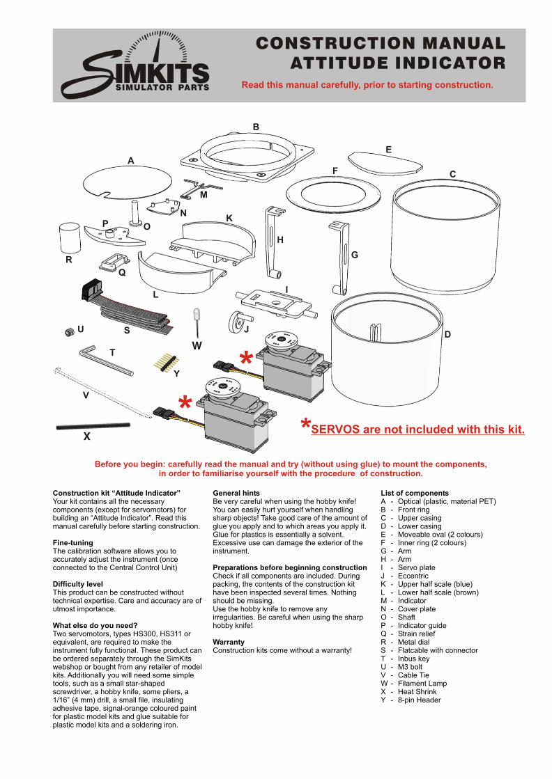
Construction kit “Attitude Indicator” General hints List of componentsYour kit contains all the necessary Be very careful when using the hobby knife! A - Optical (plastic, material PET)components (except for servomotors) for You can easily hurt yourself when handling B - Front ringbuilding an “Attitude Indicator”. Read this sharp objects! Take good care of the amount of C - Upper casingmanual carefully before starting construction. glue you apply and to which areas you apply it. D - Lower casing
Glue for plastics is essentially a solvent. E - Moveable oval (2 colours)Fine-tuning Excessive use can damage the exterior of the F - Inner ring (2 colours)The calibration software allows you to instrument. G - Armaccurately adjust the instrument (once H - Armconnected to the Central Control Unit) Preparations before beginning construction I - Servo plate
Check if all components are included. During J - EccentricDifficulty level packing, the contents of the construction kit K - Upper half scale (blue)This product can be constructed without have been inspected several times. Nothing L - Lower half scale (brown)technical expertise. Care and accuracy are of should be missing. M - Indicatorutmost importance. Use the hobby knife to remove any N - Cover plate
irregularities. Be careful when using the sharp O - ShaftWhat else do you need? hobby knife! P - Indicator guideTwo servomotors, types HS300, HS311 or Q - Strain reliefequivalent, are required to make the Warranty R - Metal dialinstrument fully functional. These product can Construction kits come without a warranty! S - Flatcable with connectorbe ordered separately through the SimKits T - Inbus keywebshop or bought from any retailer of model U - M3 boltkits. Additionally you will need some simple V - Cable Tietools, such as a small star-shaped W - Filament Lampscrewdriver, a hobby knife, some pliers, a X - Heat Shrink1/16” (4 mm) drill, a small file, insulating Y - 8-pin Header adhesive tape, signal-orange coloured paint for plastic model kits and glue suitable for plastic model kits and a soldering iron.
A
B
C
D
E
F
G
H
I
J
K
L
M
N
OP
Q
R
S
SERVOS are not included with this kit.
T
U
V
**
*Before you begin: carefully read the manual and try (without using glue) to mount the components,
in order to familiarise yourself with the procedure of construction.
Read this manual carefully, prior to starting construction.
K
X
W
Y
SSIMULATOR PARTS
B
A
D
C
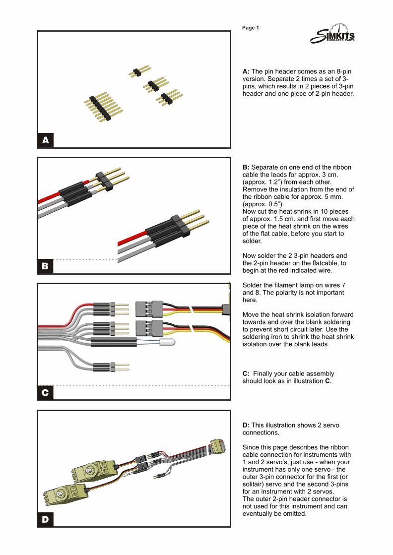
A: The pin header comes as an 8-pin version. Separate 2 times a set of 3-pins, which results in 2 pieces of 3-pin header and one piece of 2-pin header.
B: Separate on one end of the ribbon cable the leads for approx. 3 cm. (approx. 1.2”) from each other. Remove the insulation from the end of the ribbon cable for approx. 5 mm. (approx. 0.5”).Now cut the heat shrink in 10 pieces of approx. 1.5 cm. and first move each piece of the heat shrink on the wires of the flat cable, before you start to solder.
Now solder the 2 3-pin headers and the 2-pin header on the flatcable, to begin at the red indicated wire.
Solder the filament lamp on wires 7 and 8. The polarity is not important here.
Move the heat shrink isolation forward towards and over the blank soldering to prevent short circuit later. Use the soldering iron to shrink the heat shrink isolation over the blank leads
C: Finally your cable assembly should look as in illustration C.
D: This illustration shows 2 servo connections.
Since this page describes the ribbon cable connection for instruments with 1 and 2 servo’s, just use - when your instrument has only one servo - the outer 3-pin connector for the first (or solitair) servo and the second 3-pins for an instrument with 2 servos.The outer 2-pin header connector is not used for this instrument and can eventually be omitted.
Page 1
17
SSIMULATOR PARTS
2
1
4
3
Page 2
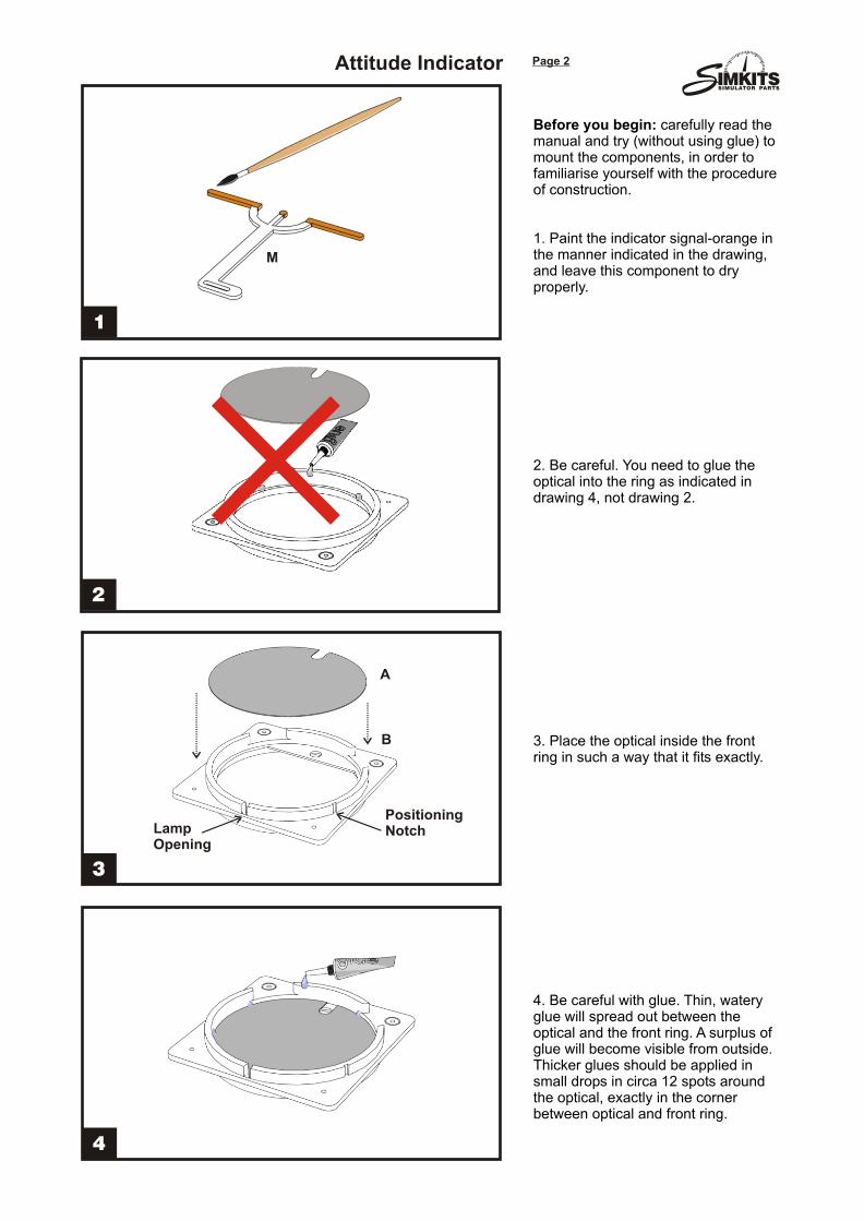
Before you begin: carefully read the manual and try (without using glue) to mount the components, in order to familiarise yourself with the procedure of construction.
1. Paint the indicator signal-orange in the manner indicated in the drawing, and leave this component to dry properly.
2. Be careful. You need to glue the optical into the ring as indicated in drawing 4, not drawing 2.
3. Place the optical inside the front ring in such a way that it fits exactly.
4. Be careful with glue. Thin, watery glue will spread out between the optical and the front ring. A surplus of glue will become visible from outside.Thicker glues should be applied in small drops in circa 12 spots around the optical, exactly in the corner between optical and front ring.
A
B
M
Positioning NotchLamp
Opening
Attitude Indicator
SSIMULATOR PARTS
6
5
8
7
Page 3
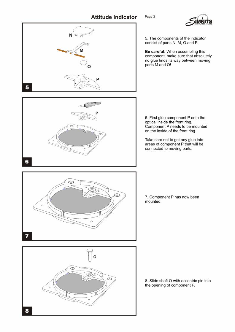
5. The components of the indicator consist of parts N, M, O and P.
Be careful: When assembling this component, make sure that absolutely no glue finds its way between moving parts M and O!
6. First glue component P onto the optical inside the front ring. Component P needs to be mounted on the inside of the front ring.
Take care not to get any glue into areas of component P that will be connected to moving parts.
7. Component P has now been mounted.
8. Slide shaft O with eccentric pin into the opening of component P.
P
O
M
N
P
O
Attitude Indicator
SSIMULATOR PARTS
10
9
12
11
Page 4
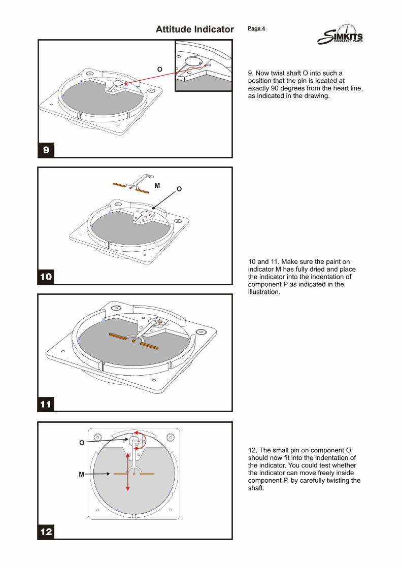
9. Now twist shaft O into such a position that the pin is located at exactly 90 degrees from the heart line, as indicated in the drawing.
10 and 11. Make sure the paint on indicator M has fully dried and place the indicator into the indentation of component P as indicated in the illustration.
12. The small pin on component O should now fit into the indentation of the indicator. You could test whether the indicator can move freely inside component P, by carefully twisting the shaft.
O
M
O
O
M
Attitude Indicator
SSIMULATOR PARTS
14
13
16
15
Page 5
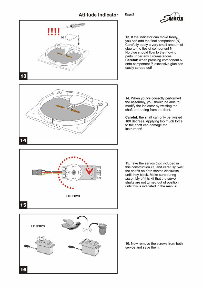
13. If the indicator can move freely, you can add the final component (N).Carefully apply a very small amount of glue to the tips of component N.No glue should flow to the moving parts under any circumstances!Careful: when pressing component N onto component P, excessive glue can easily spread out!
14. When you've correctly performed the assembly, you should be able to modify the indicator by twisting the shaft protruding from the front.
Careful: the shaft can only be twisted 180 degrees. Applying too much force to the shaft can damage the instrument!
15. Take the servos (not included in this construction kit) and carefully twist the shafts on both servos clockwise until they block. Make sure during assembly of this kit that the servo shafts are not turned out of position until this is indicated in the manual.
16. Now remove the screws from both servos and save them.
2 X SERVO
2 X SERVO
!!!!N
Attitude Indicator
SSIMULATOR PARTS
18
17
20
19
Page 6
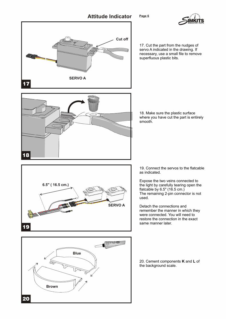
17. Cut the part from the nudges of servo A indicated in the drawing. If necessary, use a small file to remove superfluous plastic bits.
18. Make sure the plastic surface where you have cut the part is entirely smooth.
19. Connect the servos to the flatcable as indicated.
Expose the two veins connected to the light by carefully tearing open the flatcable by 6.5" (16.5 cm.)The remaining 2-pin connector is not used.
Detach the connections and remember the manner in which they were connected. You will need to restore the connection in the exact same manner later.
20. Cement components K and L of the background scale.
Cut off
Blue
Brown
SERVO A
SERVO A
6.5" ( 16.5 cm.)
Attitude Indicator
SSIMULATOR PARTS
22
21
24
23
Page 7
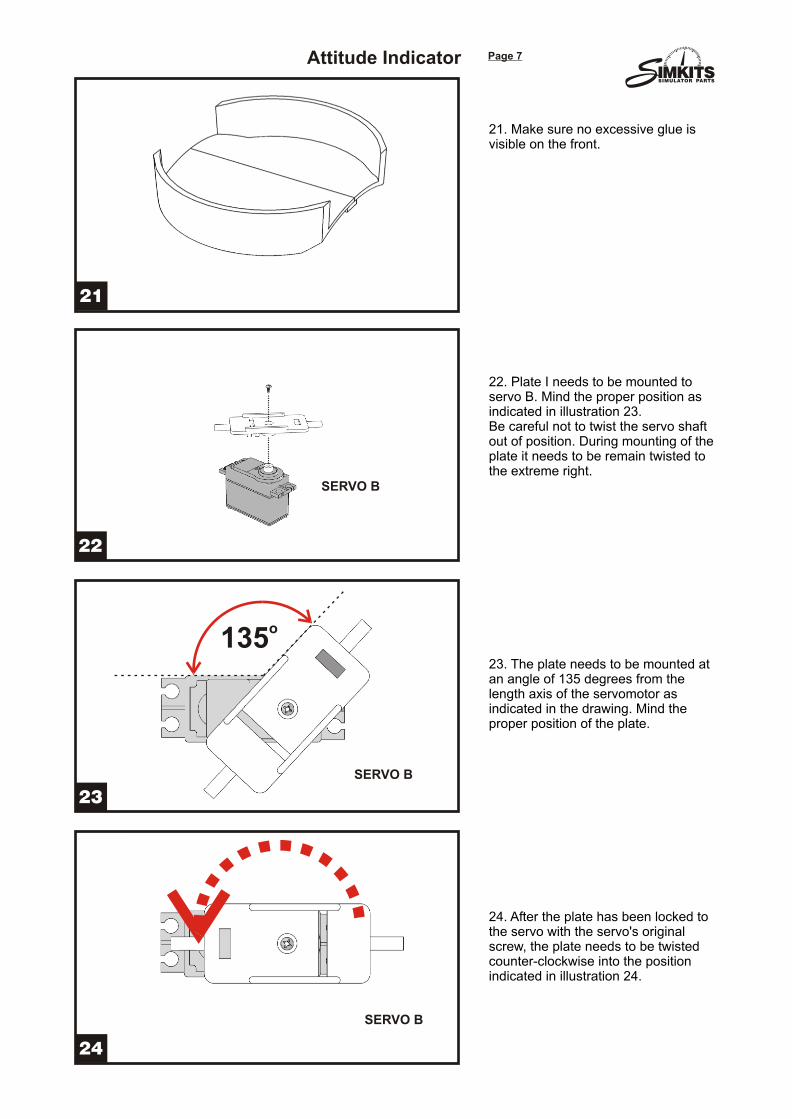
21. Make sure no excessive glue is visible on the front.
22. Plate I needs to be mounted to servo B. Mind the proper position as indicated in illustration 23.Be careful not to twist the servo shaft out of position. During mounting of the plate it needs to be remain twisted to the extreme right.
23. The plate needs to be mounted at an angle of 135 degrees from the length axis of the servomotor as indicated in the drawing. Mind the proper position of the plate.
24. After the plate has been locked to the servo with the servo's original screw, the plate needs to be twisted counter-clockwise into the position indicated in illustration 24.
o135
SERVO B
SERVO B
SERVO B
Attitude Indicator
SSIMULATOR PARTS
26
25
28
27
Page 8
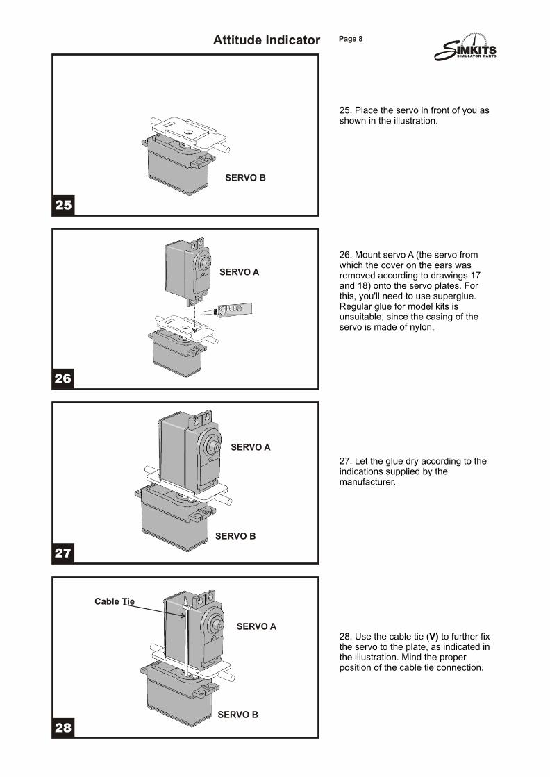
25. Place the servo in front of you as shown in the illustration.
26. Mount servo A (the servo from which the cover on the ears was removed according to drawings 17 and 18) onto the servo plates. For this, you'll need to use superglue. Regular glue for model kits is unsuitable, since the casing of the servo is made of nylon.
27. Let the glue dry according to the indications supplied by the manufacturer.
28. Use the cable tie (V) to further fix the servo to the plate, as indicated in the illustration. Mind the proper position of the cable tie connection.
SERVO B
SERVO A
SERVO A
SERVO A
SERVO B
SERVO B
Cable Tie
Attitude Indicator
SSIMULATOR PARTS
30
29
32
31
Page 9
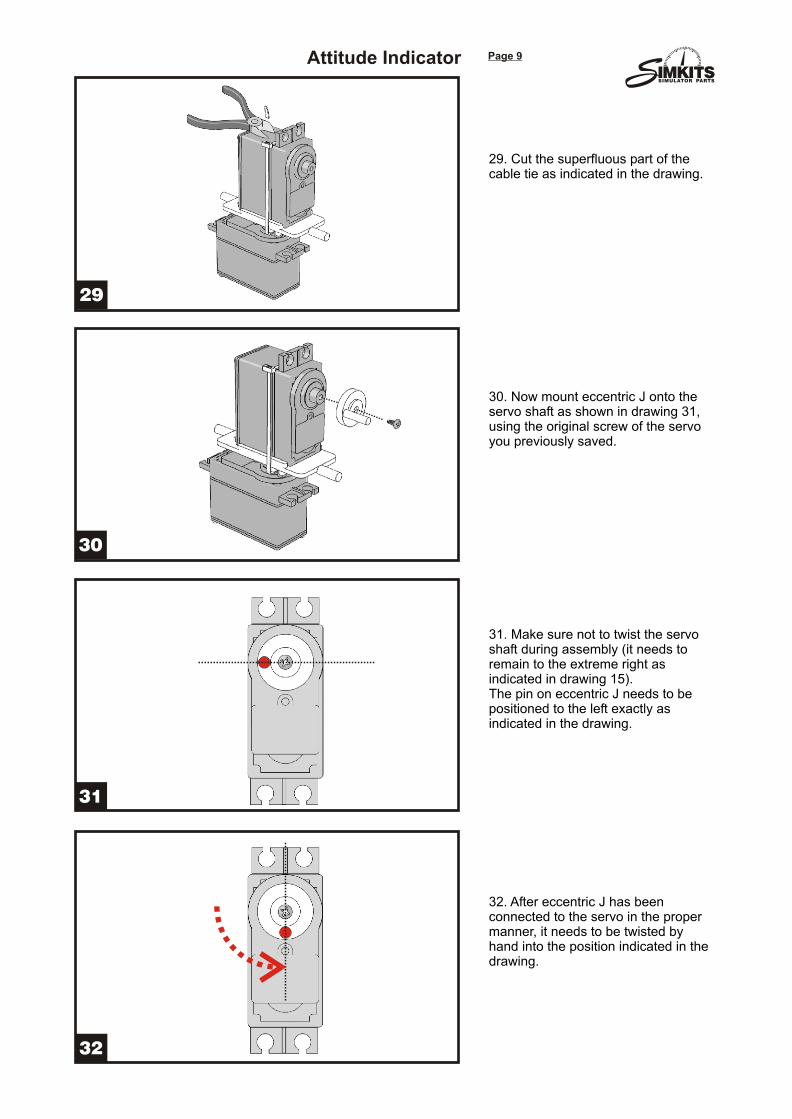
29. Cut the superfluous part of the cable tie as indicated in the drawing.
30. Now mount eccentric J onto the servo shaft as shown in drawing 31, using the original screw of the servo you previously saved.
31. Make sure not to twist the servo shaft during assembly (it needs to remain to the extreme right as indicated in drawing 15).The pin on eccentric J needs to be positioned to the left exactly as indicated in the drawing.
32. After eccentric J has been connected to the servo in the proper manner, it needs to be twisted by hand into the position indicated in the drawing.
Attitude Indicator
SSIMULATOR PARTS
34
33
36
35
Page 10
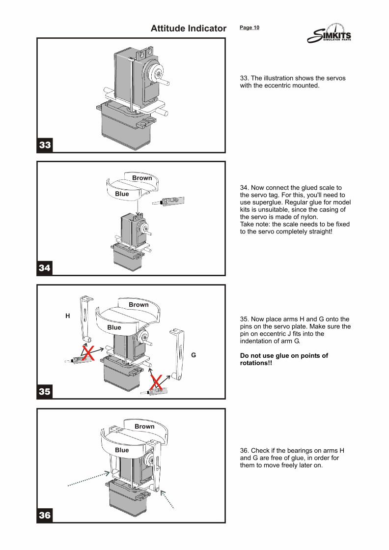
33. The illustration shows the servos with the eccentric mounted.
34. Now connect the glued scale to the servo tag. For this, you'll need to use superglue. Regular glue for model kits is unsuitable, since the casing of the servo is made of nylon.Take note: the scale needs to be fixed to the servo completely straight!
35. Now place arms H and G onto the pins on the servo plate. Make sure the pin on eccentric J fits into the indentation of arm G.
Do not use glue on points of rotations!!
36. Check if the bearings on arms H and G are free of glue, in order for them to move freely later on.
X
X
Brown
Brown
Brown
Blue
Blue
Blue
H
G
Attitude Indicator
SSIMULATOR PARTS
38
37
40
39
Page 11
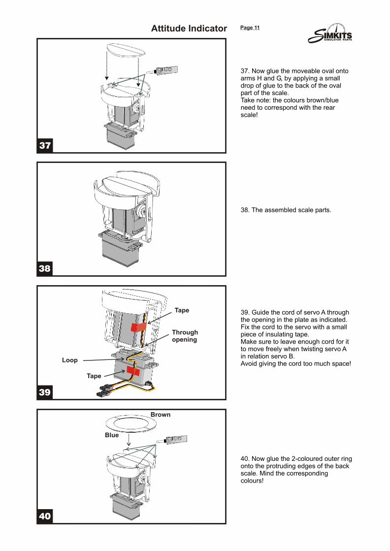
37. Now glue the moveable oval onto arms H and G, by applying a small drop of glue to the back of the oval part of the scale.Take note: the colours brown/blue need to correspond with the rear scale!
38. The assembled scale parts.
39. Guide the cord of servo A through the opening in the plate as indicated. Fix the cord to the servo with a small piece of insulating tape.Make sure to leave enough cord for it to move freely when twisting servo A in relation servo B.Avoid giving the cord too much space!
40. Now glue the 2-coloured outer ring onto the protruding edges of the back scale. Mind the corresponding colours!
Loop
Throughopening
Tape
Tape
Brown
Blue
Attitude Indicator
SSIMULATOR PARTS
42
41
44
43
Page 12
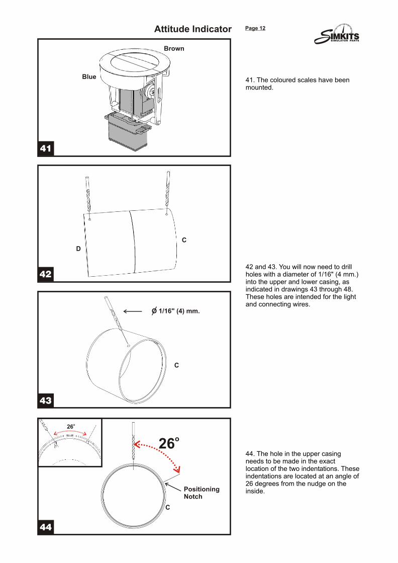
41. The coloured scales have been mounted.
42 and 43. You will now need to drill holes with a diameter of 1/16" (4 mm.) into the upper and lower casing, as indicated in drawings 43 through 48. These holes are intended for the light and connecting wires.
44. The hole in the upper casing needs to be made in the exact location of the two indentations. These indentations are located at an angle of 26 degrees from the nudge on the inside.
C
D
C
C
O 1/16" (4) mm.
o26
PositioningNotch
o26
Blue
Brown
Attitude Indicator
SSIMULATOR PARTS
46
45
48
47
Page 13
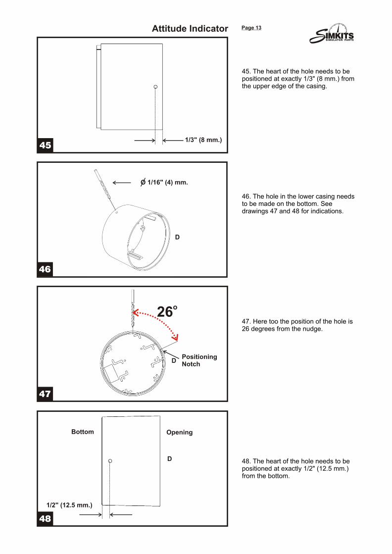
45. The heart of the hole needs to be positioned at exactly 1/3" (8 mm.) from the upper edge of the casing.
46. The hole in the lower casing needs to be made on the bottom. See drawings 47 and 48 for indications.
47. Here too the position of the hole is 26 degrees from the nudge.
48. The heart of the hole needs to be positioned at exactly 1/2" (12.5 mm.) from the bottom.
D
D
D
O 1/16" (4) mm.
1/2" (12.5 mm.)
1/3" (8 mm.)
o26
PositioningNotch
Bottom Opening
Attitude Indicator
SSIMULATOR PARTS
50
49
52
51
Page 14
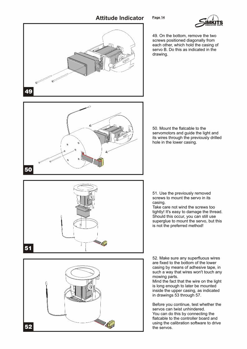
49. On the bottom, remove the two screws positioned diagonally from each other, which hold the casing of servo B. Do this as indicated in the drawing.
50. Mount the flatcable to the servomotors and guide the light and its wires through the previously drilled hole in the lower casing.
51. Use the previously removed screws to mount the servo in its casing.Take care not wind the screws too tightly! It's easy to damage the thread. Should this occur, you can still use superglue to mount the servo, but this is not the preferred method!
52. Make sure any superfluous wires are fixed to the bottom of the lower casing by means of adhesive tape, in such a way that wires won't touch any mowing parts.Mind the fact that the wire on the light is long enough to later be mounted inside the upper casing, as indicated in drawings 53 through 57.
Before you continue, test whether the servos can twist unhindered. You can do this by connecting the flatcable to the controller board and using the calibration software to drive the servos.
Attitude Indicator
SSIMULATOR PARTS
54
53
56
55
Page 15
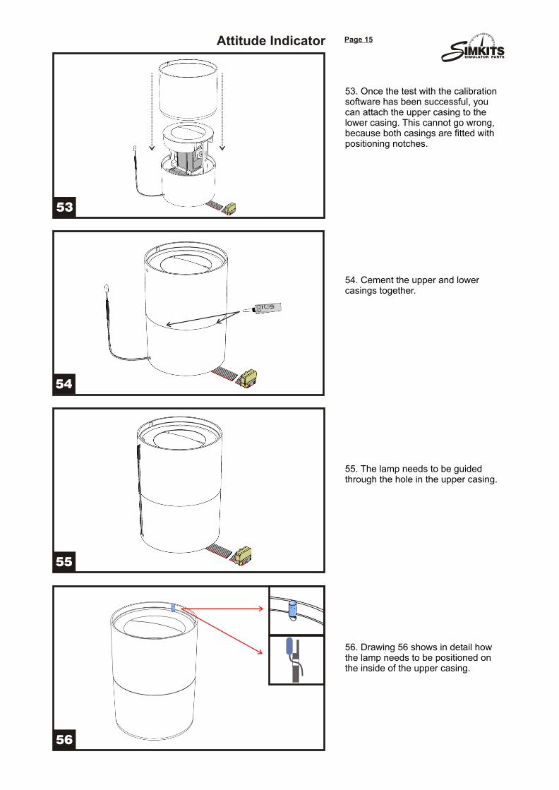
53. Once the test with the calibration software has been successful, you can attach the upper casing to the lower casing. This cannot go wrong, because both casings are fitted with positioning notches.
54. Cement the upper and lower casings together.
55. The lamp needs to be guided through the hole in the upper casing.
56. Drawing 56 shows in detail how the lamp needs to be positioned on the inside of the upper casing.
Attitude Indicator
SSIMULATOR PARTS
58
57
60
59
Page 16
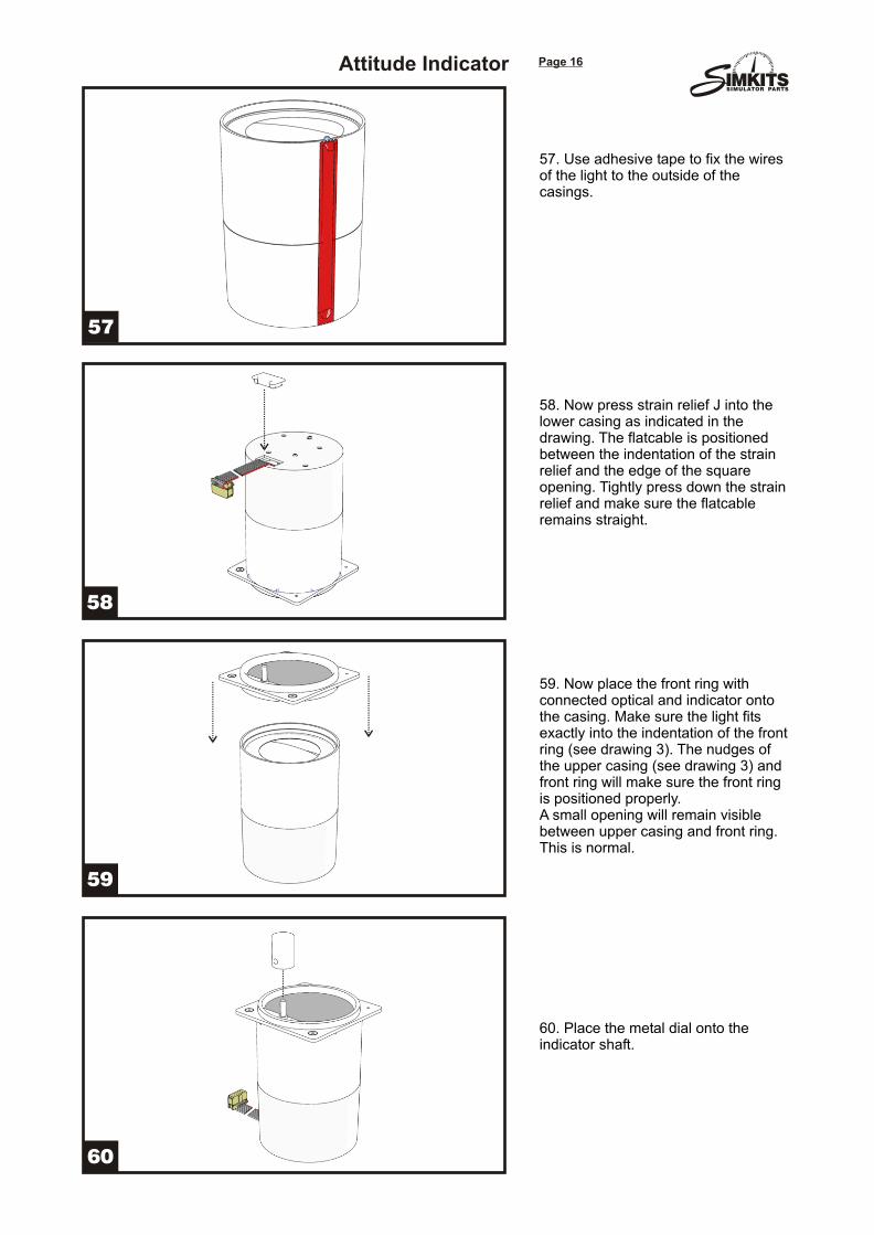
57. Use adhesive tape to fix the wires of the light to the outside of the casings.
58. Now press strain relief J into the lower casing as indicated in the drawing. The flatcable is positioned between the indentation of the strain relief and the edge of the square opening. Tightly press down the strain relief and make sure the flatcable remains straight.
59. Now place the front ring with connected optical and indicator onto the casing. Make sure the light fits exactly into the indentation of the front ring (see drawing 3). The nudges of the upper casing (see drawing 3) and front ring will make sure the front ring is positioned properly.A small opening will remain visible between upper casing and front ring. This is normal.
60. Place the metal dial onto the indicator shaft.
Attitude Indicator
SSIMULATOR PARTS
62
61
Page 17
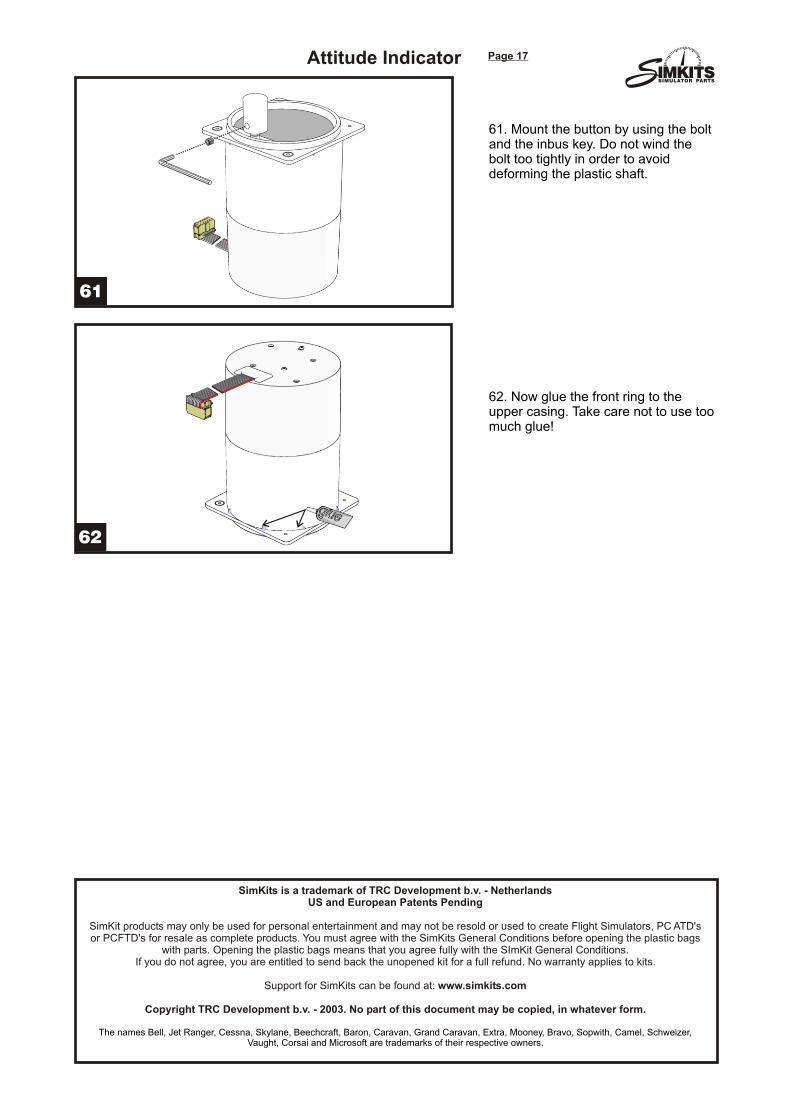
61. Mount the button by using the bolt and the inbus key. Do not wind the bolt too tightly in order to avoid deforming the plastic shaft.
62. Now glue the front ring to the upper casing. Take care not to use too much glue!
SimKits is a trademark of TRC Development b.v. - NetherlandsUS and European Patents Pending
SimKit products may only be used for personal entertainment and may not be resold or used to create Flight Simulators, PC ATD's or PCFTD's for resale as complete products. You must agree with the SimKits General Conditions before opening the plastic bags
with parts. Opening the plastic bags means that you agree fully with the SImKit General Conditions. If you do not agree, you are entitled to send back the unopened kit for a full refund. No warranty applies to kits.
Support for SimKits can be found at: www.simkits.com
Copyright TRC Development b.v. - 2003. No part of this document may be copied, in whatever form.
The names Bell, Jet Ranger, Cessna, Skylane, Beechcraft, Baron, Caravan, Grand Caravan, Extra, Mooney, Bravo, Sopwith, Camel, Schweizer, Vaught, Corsai and Microsoft are trademarks of their respective owners.
Attitude Indicator