atv 31 summary of functions
TRANSCRIPT

2
Variable speed drives for asynchronous motors Altivar 31
Summary of functions Drive factory setting
Presentation page 60270/3
Functions of the display and keysPresentation page 60270/3Remote display terminal option page 60270/4Menu access levels page 60270/4Menu access code page 60270/4
Application functionsOperating speed range page 60270/4Acceleration and deceleration ramp times page 60270/4Acceleration and deceleration ramp profi le page 60270/5Ramp switching page 60270/5Automatic adaptation of deceleration ramp page 60270/6Voltage/frequency ratio page 60270/6Auto-tuning page 60270/6Switching frequency, noise reduction page 60270/6Skip frequencies page 60270/7Speed reference page 60270/7Analog inputs page 60270/7Preset speeds page 60270/7+/- speed page 60270/8Save reference page 60270/8Jog operation page 60270/9Control and reference channels page 60270/9Reference switching page 60270/9Summing inputs page 60270/9PI regulator page 60270/10Current limit switching page 60270/10Limiting low speed operating time page 60270/10Motor switching page 60270/10Control mode switching page 60270/112-wire control page 60270/113-wire control page 60270/11Forced local mode page 60270/11Freewheel stop page 60270/11Fast stop page 60270/11DC injection stop page 60270/11Brake control page 60270/12Management of limit switch page 60270/12Monitoring page 60270/12Fault management page 60270/13Fault reset page 60270/13General reset (disables all faults) page 60270/13Controlled stop on loss of line supply page 60270/13Stop mode in the event of a fault page 60270/13Automatic catching of a spinning load with speed detection page 60270/14Automatic restart page 60270/14Derated operation in the event of an undervoltage page 60270/14Fault relay, unlocking page 60270/14Operating time reset to zero page 60270/14Motor thermal protection page 60270/15Drive thermal protection page 60270/15R1, R2 relay confi guration page 60270/15AOC/AOV analog outputs page 60270/16Saving and retrieving the confi guration page 60270/16
Spooling functionsTraverse Control page 60270/17Counter Wobble page 60270/18
Compatibility of functionsFunction compatibility table page 60270/19
PowerSuite for PC welcome screen
5637
12
PowerSuite for PC welcome screen
5637
12
Presentation:page 60260/2
Characteristics:page 60261/2
References:page 60262/2
Dimensions:page 60263/2
Schemes:page 60264/2
Presentation:page 60260/2
Characteristics:page 60261/2
References:page 60262/2
Dimensions:page 60263/2
Schemes:page 60264/2
Presentation:page 60260/2
Characteristics:page 60261/2
References:page 60262/2
Dimensions:page 60263/2
Schemes:page 60264/2
Presentation:page 60260/2
Characteristics:page 60261/2
References:page 60262/2
Dimensions:page 60263/2
Schemes:page 60264/2
Functions2
60270-EN_Ver5.0.indd
1
2
3
4
5
6
7
8
9
10

3
Variable speed drives for asynchronous motors Altivar 31
Drive factory settingThe drive is supplied ready for use in most applications, with the following functions and settings:
b Nominal motor frequency: 50 Hzb Motor voltage: 230 V (ATV 31HpppM2 and M3X), 400 V (ATV 31HpppN4) or 600 V (ATV 31HpppS6X)b Linear ramp times: 3 secondsb Low speed (LSP): 0 Hz, high speed (HSP): 50 Hzb Normal stop mode on deceleration rampb Stop mode in the event of a fault: Freewheelb Motor thermal current = nominal drive currentb Standstill injection braking current = 0.7 x nominal drive current, for 0.5 secondsb Constant torque operation, with sensorless fl ux vector controlb Logic inputs: v 2 directions of operation (LI1, LI2), 2-wire controlv 4 preset speeds (LI3, LI4): LSP (low speed), 10 Hz, 15 Hz, 20 Hzb Analog inputs: v AI1 speed reference (0 +10 V)v AI2 (0 ± 10 V) summing of AI1v AI3 (4-20 mA) not confi guredb Relay R1: fault relayb Relay R2: not assignedb Analog output AOC: 0-20 mA, image of the motor frequencyb Automatic adaptation of the deceleration ramp in the event of excessive brakingb Switching frequency 4 kHz, random frequency
Functions of the display and keys
1 Information is displayed in the form of codes or values in four 7-segment displays2 Buttons for scrolling through the menus or modifying values.3 ENT: Validation button for entering a menu or confi rming the new value selected.4 ESC: Button for exiting the menus (no confi rmation)5 2 diagnostic LEDs for the CANopen bus
b For ATV 31HppppM2A, ATV 31HpppM3XA and ATV 31HpppN4A drives only:6 Speed reference potentiometer7 RUN: Local control of motor operation8 STOP/RESET: Controls motor stopping locally and resets any faults
7
2
6
3
4
5
7
2
6
3
4
5
Presentation:page 60260/2
Characteristics:page 60261/2
References:page 60262/2
Dimensions:page 60263/2
Schemes:page 60264/2
Presentation:page 60260/2
Characteristics:page 60261/2
References:page 60262/2
Dimensions:page 60263/2
Schemes:page 60264/2
Presentation:page 60260/2
Characteristics:page 60261/2
References:page 60262/2
Dimensions:page 60263/2
Schemes:page 60264/2
Presentation:page 60260/2
Characteristics:page 60261/2
References:page 60262/2
Dimensions:page 60263/2
Schemes:page 60264/2
8
1
Functions (continued)2
60270-EN_Ver5.0.indd
1
2
3
4
5
6
7
8
9
10

4
Variable speed drives for asynchronous motors Altivar 31
b Remote display terminal option The remote display terminal can be mounted on the door of a wall-fi xing or fl oor-standing enclosure.It comprises an LCD display with programming and control keys and a switch for locking access to the menus.Drive control keys:v FWD/RV: reversal of the direction of rotationv RUN: motor run commandv STOP/RESET: motor stop command or fault resetThe speed reference is given by the remote display terminal. Only the freewheel, fast stop and DC injection stop commands remain active on the terminals. If the drive/operator terminal link is broken, the drive locks in fault mode.Its subsequent action depends on the control and reference channel programming.Note: Protection via customer confi dential code has priority over the switch.
b Menu access levelsThere are 3 access levels:v Level 1: access to standard functions. Signifi cantly, this level is interchangeable with the Altivar 28.v Level 2: access to advanced application functions.v Level 3: access to advanced application functions and management of mixed control modes.
b Menu access codeEnables the drive confi guration to be protected using an access code.When access is locked using a code, only the adjustment and monitoring parameters can be accessed.
Application functionsb Operating speed rangeUsed to determine the 2 frequency limits which defi ne the speed range permitted by the machine under actual operating conditions for all applications with or without overspeed.
LSP: low speed, from 0 to HSP, factory setting 0HSP: high speed, from LSP to f max., factory setting 50 Hzx : confi gurable between 0 and 20 mA, factory setting 4 mAy: confi gurable between 4 and 20 mA, factory setting 20 mA
b Acceleration and deceleration ramp times Used to defi ne acceleration and deceleration ramp times according to the application and the machine dynamics.
Linear acceleration ramp Linear deceleration rampt1: acceleration timet2: deceleration timet1 and t2 can be set independently between 0.1 and 999.9 s, factory setting: 3 s
ESC
ENT
RUNFWO
REV
stopreset
5632
20
Remote display terminal
ESC
ENT
RUNFWO
REV
stopreset
5632
20
Remote display terminal
f (Hz)
HSP
LSP
0 Vx mA4 mA
10 Vy mA20 mA
Reference
f (Hz)
HSP
LSP
0 Vx mA4 mA
10 Vy mA20 mA
Reference
Ramp adjustment with PowerSuite for PC
5637
14
Ramp adjustment with PowerSuite for PC
5637
14
50
f (Hz)
0t1
t
50
f (Hz)
0t1
t
50
f (Hz)
0t2
t
50
f (Hz)
0t2
t
Presentation:page 60260/2
Characteristics:page 60261/2
References:page 60262/2
Dimensions:page 60263/2
Schemes:page 60264/2
Presentation:page 60260/2
Characteristics:page 60261/2
References:page 60262/2
Dimensions:page 60263/2
Schemes:page 60264/2
Presentation:page 60260/2
Characteristics:page 60261/2
References:page 60262/2
Dimensions:page 60263/2
Schemes:page 60264/2
Presentation:page 60260/2
Characteristics:page 60261/2
References:page 60262/2
Dimensions:page 60263/2
Schemes:page 60264/2
Functions (continued)2
60270-EN_Ver5.0.indd
1
2
3
4
5
6
7
8
9
10

5
Variable speed drives for asynchronous motors2 Altivar 31
b Acceleration and deceleration ramp profi leUsed to gradually increase the output frequency starting from a speed reference, following a linear ratio or a preset ratio. v For applications such as material handling, packaging, transportation of people: the use of S ramps takes up mechanical play and eliminates jolts, and limits “non-following” of speed during rapid transient operation of high inertia machines.v For pumping applications (installation with centrifugal pump and non-return valve): valve closing can be controlled more accurately if U ramps are used. v Selecting “linear”, “S”, “U” or customized profi les assigns both the acceleration and deceleration ramps.
S ramps U ramps Customized ramps
HSP: high speedt1: ramp time sett2 = 0.6 x t1The curve coeffi cient is fi xed.
HSP: high speedt1: ramp time sett2 = 0.5 x t1The curve coeffi cient is fi xed.
HSP: high speedtA1: can be set between 0 and 100% (of ACC or AC2)tA2: can be set between 0 and (100% - tA1) (of ACC or AC2)tA3: can be set between 0 and 100% (of dEC or dE2)tA4: can be set between 0 and (100% - tA3) (of dEC or dE2)ACC: acceleration ramp 1 timeAC2: acceleration ramp 2 timedEC: deceleration ramp 1 timedE2: deceleration ramp 2 time
b Ramp switchingUsed to switch 2 acceleration and deceleration ramp times, which can be adjusted separately. Ramp switching can be enabled by:v a logic inputv a frequency thresholdv a combination of logic input and frequency threshold
Function suitable for:v material handling with smooth starting and approachv machines with fast steady state speed correction
Example of switching using logic input LI4
f (Hz) f (Hz)
HSP HSP
0 0t tt2
t1
t2
t1
f (Hz) f (Hz)
HSP HSP
0 0t tt2
t1
t2
t1
f (Hz)
HSP
0 tt2
t1
f (Hz)
HSP
0 tt2
t1
f (Hz)
HSP
0 tt2
t1
f (Hz)
HSP
0 tt2
t1
f (Hz)
HSP
0 ttA1
ACC or AC2
f (Hz)
HSP
0 ttA2 tA3 tA4
dEC or dE2
f (Hz)
HSP
0 ttA1
ACC or AC2
f (Hz)
HSP
0 ttA2 tA3 tA4
dEC or dE2
t
t
f(Hz)
0
1
LI4 0
1
t
AC2
ACC
Forwardorreverse
dE2
dEC
Acceleration 1 (ACC) and deceleration 1 (dEC):- adjustment 0.1 to 999.9 s- factory setting 3 sAcceleration 2 (AC2) and deceleration 2 (dE2):- adjustment 0.1 to 999.9 s- factory setting 5 sHSP: high speed
HSP
t
t
f(Hz)
0
1
LI4 0
1
t
AC2
ACC
Forwardorreverse
dE2
dEC
Acceleration 1 (ACC) and deceleration 1 (dEC):- adjustment 0.1 to 999.9 s- factory setting 3 sAcceleration 2 (AC2) and deceleration 2 (dE2):- adjustment 0.1 to 999.9 s- factory setting 5 sHSP: high speed
HSP
Presentation:page 60260/2
Characteristics:page 60261/2
References:page 60262/2
Dimensions:page 60263/2
Schemes:page 60264/2
Presentation:page 60260/2
Characteristics:page 60261/2
References:page 60262/2
Dimensions:page 60263/2
Schemes:page 60264/2
Presentation:page 60260/2
Characteristics:page 60261/2
References:page 60262/2
Dimensions:page 60263/2
Schemes:page 60264/2
Presentation:page 60260/2
Characteristics:page 60261/2
References:page 60262/2
Dimensions:page 60263/2
Schemes:page 60264/2
Functions (continued)2
60270-EN_Ver5.0.indd
1
2
3
4
5
6
7
8
9
10

6
Variable speed drives for asynchronous motors2 Altivar 31
b Automatic adaptation of deceleration rampUsed to automatically adapt the deceleration ramp if the initial setting is too low when the load inertia is taken into account. This function avoids the drive locking in the event of an excessive braking fault. Function suitable for all applications not requiring precise stopping and not using braking resistors.Automatic adaptation must be cancelled if the machine has position control with stopping on a ramp and a braking resistor installed. This function is automatically disabled if the brake sequence is confi gured.
b Voltage/frequency ratio v Motor and power supply characteristicsUsed to determine the limit values for the voltage/frequency ratio according to the line supply, the motor and the application.The following values should be set for variable or constant torque applications with or without overspeed:
- the base frequency corresponding to the supply- the nominal motor frequency (in Hz) given on the motor rating plate- the nominal motor voltage (in V) given on the motor rating plate- the maximum output frequency of the drive (in Hz)
v Type of voltage/frequency ratioUsed to adapt the voltage/frequency ratio to the application in order to optimize performance for the following applications:
- Constant torque applications (machines with average loads operating at low speed) with motors connected in parallel or special motors (e.g.: resistive cage motor): ratio L
- Variable torque applications (pumps, fans): ratio P- Machines with heavy loads operating at low speed, machines with fast cycles,
with (sensorless) fl ux vector control: ratio n- Energy saving, for machines with slow speed and torque variations: ratio nLd
Voltage is automatically reduced to a minimum according to the necessary torque.
Un: Nominal motor voltagefrn: Nominal motor frequency
b Auto-tuningAuto-tuning may be performed: voluntarily by the operator using dialogue tools via local control mode or the serial linkv each time the drive is switched onv on each run commandv by enabling a logic input Auto-tuning is used to optimize application performance.
b Switching frequency, noise reductionThe switching frequency setting permits a reduction in the noise generated by the motor.The switching frequency is modulated randomly in order to avoid resonance. This function can be disabled if it causes instability.Switching the intermediate DC voltage at high frequency is useful for supplying the motor with a current wave having little harmonic distortion. The switching frequency is adjustable during operation to reduce the noise generated by the motor.Value: 2 to 16 kHz, with a factory setting of 4 kHz.For all applications which require low motor noise.
Adjustment of the voltage/frequency ratio with PowerSuite for PC
5637
15
Adjustment of the voltage/frequency ratio with PowerSuite for PC
5637
15
L
nP
U (V)
Un
frnf (Hz)
L
nP
U (V)
Un
frnf (Hz)
Presentation:page 60260/2
Characteristics:page 60261/2
References:page 60262/2
Dimensions:page 60263/2
Schemes:page 60264/2
Presentation:page 60260/2
Characteristics:page 60261/2
References:page 60262/2
Dimensions:page 60263/2
Schemes:page 60264/2
Presentation:page 60260/2
Characteristics:page 60261/2
References:page 60262/2
Dimensions:page 60263/2
Schemes:page 60264/2
Presentation:page 60260/2
Characteristics:page 60261/2
References:page 60262/2
Dimensions:page 60263/2
Schemes:page 60264/2
Functions (continued)2
60270-EN_Ver5.0.indd
1
2
3
4
5
6
7
8
9
10

7
Variable speed drives for asynchronous motors Altivar 31
b Skip frequencies This function suppresses one or two critical speeds that may cause mechanical resonance.It is possible to prohibit the prolonged operation of the motor on 1 or 2 frequency bands (with a bandwidth of ± 1 Hz), which can be set within the operating range.Function suitable for lightweight machines, bulk product conveyors with unbalanced motor, fans and centrifugal pumps.
b Speed referenceThe speed reference can have different sources depending on the drive confi guration:v references provided by 3 analog inputsv the potentiometer reference (for ATV 31pppA drives only)v the +/- speed function via logic input, using the keypad or remote display terminal keysv the remote display terminal referencev speed references provided by the communication bus or networksThese different sources are managed by programming the reference functions and channels.
b Analog inputsThere are 3 analog inputs:v 2 voltage inputs:
- 0-10 V (AI1)- ± 10 V (AI2)
v 1 current input:- X-Y mA (AI3) where X is confi gurable between 0 and 20 mA, and Y is
confi gurable between 4 and 20 mA.
b Preset speeds Used to switch preset speed references.Choose between two, four, eight or sixteen preset speeds.Enabled by means of 1, 2, 3 or 4 logic inputs.The preset speeds can be adjusted in increments of 0.1 Hz from 0 Hz to 500 Hz.Function suitable for material handling and machines with several operating speeds.
Example of operation with 4 preset speeds and 2 logic inputs
2 Hz
Motor speed change depending on the skip frequency reference
Reference
f (Hz)
2 Hz
Motor speed change depending on the skip frequency reference
Reference
f (Hz)
Adjustment of preset speeds with PowerSuite for PC
5637
17
Adjustment of preset speeds with PowerSuite for PC
5637
17
1
101520
1
LI3 0
1
LI4 0
LI2 0
t
t
t
t
f (Hz)
LSP
Forwardor
Reverse
The speed obtained with inputs LI3 and LI4 at state 0 is LSP or the speed reference, depending on the level of analog inputs AI1, AI2 and AI3.
Factory settings:
1st speed: LSP (low speed or speed reference)
2nd speed: 10 Hz
3rd speed: 15 Hz
4th speed: 20 Hz (high speed)
1
101520
1
LI3 0
1
LI4 0
LI2 0
t
t
t
t
f (Hz)
LSP
Forwardor
Reverse
The speed obtained with inputs LI3 and LI4 at state 0 is LSP or the speed reference, depending on the level of analog inputs AI1, AI2 and AI3.
Factory settings:
1st speed: LSP (low speed or speed reference)
2nd speed: 10 Hz
3rd speed: 15 Hz
4th speed: 20 Hz (high speed)
Presentation:page 60260/2
Characteristics:page 60261/2
References:page 60262/2
Dimensions:page 60263/2
Schemes:page 60264/2
Presentation:page 60260/2
Characteristics:page 60261/2
References:page 60262/2
Dimensions:page 60263/2
Schemes:page 60264/2
Presentation:page 60260/2
Characteristics:page 60261/2
References:page 60262/2
Dimensions:page 60263/2
Schemes:page 60264/2
Presentation:page 60260/2
Characteristics:page 60261/2
References:page 60262/2
Dimensions:page 60263/2
Schemes:page 60264/2
Functions (continued)2
60270-EN_Ver5.0.indd
1
2
3
4
5
6
7
8
9
10

8
Variable speed drives for asynchronous motors Altivar 31
b +/- speed Used to increase or decrease a speed reference by means of 1 or 2 logic inputs, with or without the last reference being saved (motorized potentiometer function). This function is suitable for centralized control of a machine with several sections operating in one direction or for control by a pendant control station of a handling crane with two operating directions.
Two types of operation are available:v Use of single action buttons: two logic inputs are required in addition to the operating direction(s).The input assigned to the “+ speed” command increases the speed, the input assigned to the “- speed” command decreases the speed.
Example of “+/- speed” with 2 logic inputs, single action buttons and reference saving
v Use of double action buttons (only one logic input assigned to “+ speed” is necessary):
Logic inputs: Released(- speed)
1st press(speed maintained)
2nd press(+ speed)
Forward button
– a a and b
Reverse button
– c c and d
LSP: low speed, HSP: high speed
Example with double action buttons and 1 logic inputNote: This type of “+/- speed” control is incompatible with 3-wire control.
b Save referenceThis function is associated with “+/- speed” control. Enables the reading and saving of the last speed reference prior to the loss of the run command or line supply. The saved reference is applied at the next run command.
Adjustment of the “+/- speed” function with PowerSuite for PC
5637
18
Adjustment of the “+/- speed” function with PowerSuite for PC
5637
18
1
0
1
0
1
0
f (Hz)
t
t
t
t
Forwardor
Reverse
+ speed
- speed
HSP
LSP
1
0
1
0
1
0
f (Hz)
t
t
t
t
Forwardor
Reverse
+ speed
- speed
HSP
LSP
a c b d
Forward
a and c: 1st pressb and d: 2nd press
Reverse “+ speed”
a c b d
Forward
a and c: 1st pressb and d: 2nd press
Reverse “+ speed”
0
0a a
b ba a a a
c c
d
a
0
f (Hz)
t
t
t
2nd press1st press
Reverse2nd press1st press
HSP
LSP
LSP
HSP
Forward operation
0
0a a
b ba a a a
c c
d
a
0
f (Hz)
t
t
t
2nd press1st press
Reverse2nd press1st press
HSP
LSP
LSP
HSP
Forward operation
Presentation:page 60260/2
Characteristics:page 60261/2
References:page 60262/2
Dimensions:page 60263/2
Schemes:page 60264/2
Presentation:page 60260/2
Characteristics:page 60261/2
References:page 60262/2
Dimensions:page 60263/2
Schemes:page 60264/2
Presentation:page 60260/2
Characteristics:page 60261/2
References:page 60262/2
Dimensions:page 60263/2
Schemes:page 60264/2
Presentation:page 60260/2
Characteristics:page 60261/2
References:page 60262/2
Dimensions:page 60263/2
Schemes:page 60264/2
Functions (continued)2
60270-EN_Ver5.0.indd
1
2
3
4
5
6
7
8
9
10

9
Variable speed drives for asynchronous motors Altivar 31
b Jog operation Used for pulse operation with minimum ramp times (0.1 s), limited speed reference and minimum time between 2 pulses. Enabled by a logic input and pulses given by the operating direction command.
This function is suitable for machines with product insertion in manual mode(example: gradual movement of the mechanism during maintenance operations).
b Control and reference channelsThere are several control and reference channels which can be independent.Commands (forward, reverse, etc.) and speed references can be sent using the following methods:v terminals (logic and analog inputs)v keypad for ATV 31pppA only (RUN/STOP and potentiometer)v ATV 31 keypadv via the serial link
- remote display terminal- Modbus control word- CANopen control word
The control and speed reference channels can be separate.Example: speed reference issued by CANopen and command issued by the remote display terminal.Note: The Stop keys on the keypad and the remote display terminal may retain priority.The summing inputs and PI regulator functions only apply to one reference channel.
b Reference switchingSwitching between 2 speed references can be enabled via:v a logic inputv a bit in a Modbus or CANopen control wordReference 1 is active if the logic input (or control word bit) is at 0, reference 2 is active if the logic input (or control word bit) is at 1.The reference can be switched with the motor running.
b Summing inputsUsed to add up 2 or 3 speed references from different sources.The references to be added together are selected from all the possible types of speed reference.Example: Reference 1 sent by AI1Reference 2 sent by AI2Reference 3 sent by AIPDrive speed reference: reference 1 + reference 2 + reference 3.
1
0
1
0
f (Hz)
Forward or Reverse
Speed reference:can be adjusted from 0 to 10 Hz,factory setting 10 Hz.
t
t
ttm
JOGtm: fi xed time of 0.5 s, minimum time between 2 pulses
Example of jog operation
1
0
1
0
f (Hz)
Forward or Reverse
Speed reference:can be adjusted from 0 to 10 Hz,factory setting 10 Hz.
t
t
ttm
JOGtm: fi xed time of 0.5 s, minimum time between 2 pulses
Example of jog operation
1
0
1
AI2
AI1
LIx 0
f (Hz)
t
t
t
Forwardor
Reverse
Example of reference switching
1
0
1
AI2
AI1
LIx 0
f (Hz)
t
t
t
Forwardor
Reverse
Example of reference switching
LIx
CO
M
AI1
AI2
AI3
+ 24 V
±10 V X-Y
+10
0
Connection diagram for reference switching
(X is adjustable from 0 to 20 mAand Y is adjustable from 4 to 20 mA)
LIx
CO
M
AI1
AI2
AI3
+ 24 V
±10 V X-Y
+10
0
Connection diagram for reference switching
(X is adjustable from 0 to 20 mAand Y is adjustable from 4 to 20 mA)
Presentation:page 60260/2
Characteristics:page 60261/2
References:page 60262/2
Dimensions:page 60263/2
Schemes:page 60264/2
Presentation:page 60260/2
Characteristics:page 60261/2
References:page 60262/2
Dimensions:page 60263/2
Schemes:page 60264/2
Presentation:page 60260/2
Characteristics:page 60261/2
References:page 60262/2
Dimensions:page 60263/2
Schemes:page 60264/2
Presentation:page 60260/2
Characteristics:page 60261/2
References:page 60262/2
Dimensions:page 60263/2
Schemes:page 60264/2
Functions (continued)2
60270-EN_Ver5.0.indd
1
2
3
4
5
6
7
8
9
10

10
Variable speed drives for asynchronous motors2 Altivar 31
b PI regulatorUsed for simple control of a fl ow rate or a pressure with a sensor which supplies a feedback signal adapted to the drive.This function is suitable for pumping and ventilation applications.
v PI reference: - internal regulator reference, adjustable from 0 to 100- regulation reference selected from all the possible types of regulation reference- preset PI references
v 2 or 4 preset PI references, adjustable from 0 to 100, require the use of 1 or 2 logic inputs respectivelyv Manual reference
- speed reference selected from all the possible types of speed reference v PI feedback:
- analog input AI1, AI2 or AI3v Auto/Man:
- logic input LI for switching operation to speed reference (Man) or PI regulation (Auto).During operation in automatic mode it is possible to adapt the process feedback, to correct inverse PI, to adjust the proportional and integral gain and to apply a ramp (time = ACC - DEC) for establishing the PI action on starting and stopping.The motor speed is limited to between LSP and HSP.Note: The PI function is incompatible with the preset speeds and JOG functions. The PI reference can also be transmitted on line via the Modbus RS 485 serial link or via the CANopen bus. b Current limit switching A 2nd current limit can be confi gured between 0.25 and 1.5 times the nominal drive current.Used to limit the torque and the temperature rise of the motor.Switching between 2 current limits can be enabled via:v a logic inputv a bit in a Modbus or CANopen control word
b Limiting low speed operating timeThe motor is stopped automatically after a period of operation at low speed (LSP) with a zero reference and a run command present.This time can be set between 0.1 and 999.9 seconds (0 corresponds to an unlimited time). Factory setting: 0 s. The motor restarts automatically on the ramp when the reference reappears or if the run command is interrupted and then re-established.This function is suitable for automatic stopping/starting on pressure-regulated pumps.
b Motor switchingAllows two motors with different powers to be supplied successively by the same drive. Switching must take place with the drive stopped and locked, using an appropriate sequence at the drive output.The function can be used to adapt the motor parameters. The following parameters are switched automatically:v nominal motor voltagev nominal motor frequencyv nominal motor currentv nominal motor speedv motor cosine Phiv selection of the type of voltage/frequency ratio for motor 2v IR compensation, motor 2v motor frequency loop gainv motor stabilityv motor slip compensationMotor thermal protection is disabled by this function.Motor switching can be enabled by:v a logic inputv a bit in a Modbus or CANopen control wordWith hoisting applications, this function enables a single drive to be used for vertical and horizontal movements.
ACCDEC
RPGRIG
PICX±1
FBS
+PI reference
PIFeed-back
Manual reference
ReferenceAuto
Man
PI inversion
PI regulator
RampMultiplier
Auto/man
ACC: AccelerationDEC: DecelerationFBS: PI feedback multiplication coeffi cientHSP: High speedPIC: Reversal of the direction of correction of the PI regulatorLSP: Low speedRIG: PI regulator integral gainRPG: PI regulator proportional gain
PI regulator
HSP
LSPACCDEC
RPGRIG
PICX±1
FBS
+PI reference
PIFeed-back
Manual reference
ReferenceAuto
Man
PI inversion
PI regulator
RampMultiplier
Auto/man
ACC: AccelerationDEC: DecelerationFBS: PI feedback multiplication coeffi cientHSP: High speedPIC: Reversal of the direction of correction of the PI regulatorLSP: Low speedRIG: PI regulator integral gainRPG: PI regulator proportional gain
PI regulator
HSP
LSP
Confi guration of current switching with PowerSuite for PC
5637
19
Confi guration of current switching with PowerSuite for PC
5637
19
Presentation:page 60260/2
Characteristics:page 60261/2
References:page 60262/2
Dimensions:page 60263/2
Schemes:page 60264/2
Presentation:page 60260/2
Characteristics:page 60261/2
References:page 60262/2
Dimensions:page 60263/2
Schemes:page 60264/2
Presentation:page 60260/2
Characteristics:page 60261/2
References:page 60262/2
Dimensions:page 60263/2
Schemes:page 60264/2
Presentation:page 60260/2
Characteristics:page 60261/2
References:page 60262/2
Dimensions:page 60263/2
Schemes:page 60264/2
Functions (continued)2
60270-EN_Ver5.0.indd
1
2
3
4
5
6
7
8
9
10

11
Variable speed drives for asynchronous motors2 Altivar 31
b Control mode switchingControl channel switching provides a choice of 2 operating modes. Switching can be enabled by:v a logic inputv a bit in a Modbus or CANopen control word
b 2-wire controlUsed to control the direction of operation by means of a stay-put contact.Enabled by means of 1 or 2 logic inputs (one or two directions).This function is suitable for all non-reversing and reversing applications.3 operating modes are possible:v detection of the state of the logic inputsv detection of a change in state of the logic inputsv detection of the state of the logic inputs with forward operation always having priority over reverse
b 3-wire control Used to control the operating direction and stopping by means of pulsed contacts. Enabled by means of 2 or 3 logic inputs (non-reversing or reversing).This function is suitable for all non-reversing and reversing applications.
b Forced local modeForced local mode imposes control via the terminals or operator terminal and prohibits all other control modes.The following references and commands are available for forced local mode: v references AI1, or AI2, or AI3 and control via logic inputsv reference and control via RUN/STOP keys and potentiometer (ATV 31pppA drives only)v reference and control via the remote display terminalThe changeover to forced local mode is enabled by a logic input.
b Freewheel stop This function stops the motor by resistive torque if the motor power supply is cut.A freewheel stop is achieved:v by confi guring a normal stop command as a freewheel stop (on disappearance of a run command or appearance of a stop command)v by enabling a logic input
b Fast stopUsed to achieve a braked stop with an acceptable deceleration ramp time (divided by 2 to 10) for the drive/motor unit to avoid locking on an excessive braking fault.Used for conveyors with emergency stop electrical braking.A fast stop is achieved:v by confi guring a normal stop as a fast stop (on disappearance of a run command or appearance of a stop command)v by enabling a logic input
b DC injection stopUsed to brake (at low speed) high inertia fans, or to maintain torque on stopping in the case of fans located in an airfl ow.A DC injection stop is achieved:v by confi guring a normal stop as a DC injection stop (on disappearance of a run command or appearance of a stop command)v by enabling a logic inputThe DC value and the standstill braking time are adjustable.
24 V LI1 LIx
Altivar 31 control terminalsLI1: ForwardLIx: Reverse
Wiring diagram for 2-wire control
24 V LI1 LIx
Altivar 31 control terminalsLI1: ForwardLIx: Reverse
Wiring diagram for 2-wire control
1
1
1
0
0
0
0
f (Hz)
Stop
Forward
Reverse
t
t
t
t
Example of operation with 3-wire control
1
1
1
0
0
0
0
f (Hz)
Stop
Forward
Reverse
t
t
t
t
Example of operation with 3-wire control
24 V LI1 LI2 LIxAltivar 31 control terminals LI1: Stop
LI2: ForwardLIx: Reverse
Wiring diagram for 3-wire control
24 V LI1 LI2 LIxAltivar 31 control terminals LI1: Stop
LI2: ForwardLIx: Reverse
Wiring diagram for 3-wire control
Presentation:page 60260/2
Characteristics:page 60261/2
References:page 60262/2
Dimensions:page 60263/2
Schemes:page 60264/2
Presentation:page 60260/2
Characteristics:page 60261/2
References:page 60262/2
Dimensions:page 60263/2
Schemes:page 60264/2
Presentation:page 60260/2
Characteristics:page 60261/2
References:page 60262/2
Dimensions:page 60263/2
Schemes:page 60264/2
Presentation:page 60260/2
Characteristics:page 60261/2
References:page 60262/2
Dimensions:page 60263/2
Schemes:page 60264/2
Functions (continued)2
60270-EN_Ver5.0.indd
1
2
3
4
5
6
7
8
9
10

12
Variable speed drives for asynchronous motors2 Altivar 31
b Brake control Used to manage control of an electromagnetic brake in synchronization with the starting and stopping of the motor to avoid jolts and load veering.The brake control sequence is managed by the drive.Values that can be adjusted for releasing the brake: current threshold and time delayValues that can be adjusted for engaging the brake: frequency threshold and time delayEnabled: by relay logic output R2 or logic output AOC assigned to brake control.Function suitable for material handling applications with movements equipped with electromagnetic brakes (hoisting) and machines requiring a parking brake (unbalanced machines).
v Principle:- Vertical lifting movement:
Maintains motor torque in an upward direction when the brake is being released and engaged, in order to hold the load, and start smoothly as soon as the brake is released.
- Horizontal lifting movement:Synchronizes brake release with the build-up torque on starting and brake engage at zero speed on stopping, in order to prevent jerking.Recommended settings for brake control for a vertical lifting application (for a horizontal lifting application set the current threshold to zero):
- Brake release current: Adjust the brake release current to the nominal current indicated on the motor. If, during testing, the torque is insuffi cient, increase the brake release current (the maximum value is imposed by the drive).
- Acceleration time: For lifting applications it is advisable to set the acceleration ramps to more than 0.5 seconds. Ensure that the drive does not change to current limiting.The same recommendation applies for deceleration.Note: For a lifting movement, a braking resistor should be used. Ensure that the settings and confi gurations selected cannot cause a drop or a loss of control of the lifted load.
- Brake release time delay t1: Adjust according to the type of brake. It is the time required for the mechanical brake to release.
- Brake engage frequency: Set to twice the nominal slip then adjust according to the result.
- Brake engage time delay t2: Adjust according to the type of brake. It is the time required for the mechanical brake to engage.
b Management of limit switchUsed to manage the operation of one or two limit switches (with 1 or 2 operating directions).Each limit (forward, reverse) is associated with a logic input. The type of stop that occurs on detection of a limit can be confi gured as normal, freewheel or fast.Following a stop, the motor is permitted to restart in the opposite direction only.
b Monitoring The following data can be displayed:v frequency referencev internal PI referencev frequency reference (absolute value)v output frequency applied to the motor (value signed in two’s complement)v output value in customer unitsv current in the motorv motor power: 100% = nominal powerv line voltagev motor thermal state: 100% : nominal thermal state, 118%: motor overload thresholdv drive thermal state:100% : nominal thermal state, 118%: drive overload thresholdv motor torque: 100% = nominal torquev last faultv operating timev auto-tuning statusv confi guration and state of logic inputsv confi guration of analog inputs
0
0
1
0
1
0
0
Speed reference
t
t
t
t
Accessible settings:t1: Brake release time delayt2: Brake engage time delay
Relay or logic output
Motor current
t
Brake release current
Speed referenceBrake engage frequency
LI forward or reverse
T
t1
t2
State of brake Engaged Released Engaged
Brake control
0
0
1
0
1
0
0
Speed reference
t
t
t
t
Accessible settings:t1: Brake release time delayt2: Brake engage time delay
Relay or logic output
Motor current
t
Brake release current
Speed referenceBrake engage frequency
LI forward or reverse
T
t1
t2
State of brake Engaged Released Engaged
Brake control
Monitoring the different parameters with PowerSuite for PC
5637
21
Monitoring the different parameters with PowerSuite for PC
5637
21
Monitoring the different parameters with the oscilloscope function in PowerSuite for PC
5637
22
Monitoring the different parameters with the oscilloscope function in PowerSuite for PC
5637
22
Presentation:page 60260/2
Characteristics:page 60261/2
References:page 60262/2
Dimensions:page 60263/2
Schemes:page 60264/2
Presentation:page 60260/2
Characteristics:page 60261/2
References:page 60262/2
Dimensions:page 60263/2
Schemes:page 60264/2
Presentation:page 60260/2
Characteristics:page 60261/2
References:page 60262/2
Dimensions:page 60263/2
Schemes:page 60264/2
Presentation:page 60260/2
Characteristics:page 60261/2
References:page 60262/2
Dimensions:page 60263/2
Schemes:page 60264/2
Functions (continued)2
60270-EN_Ver5.0.indd
1
2
3
4
5
6
7
8
9
10

13
Variable speed drives for asynchronous motors2 Altivar 31
b Fault management There are different modes of operation on a resettable fault:v freewheel stopv drive switches to the fallback speedv the drive maintains the speed at which it was operating when the fault occurred until the fault disappearsv stop on rampv fast stopThe detected resettable faults are as follows:v drive overheatingv motor overheatingv CANopen bus faultv Modbus serial link failurev external faultsv loss of 4-20 mA signal
b Fault reset Used to clear the last fault by means of a logic input. The restart conditions after a reset to zero are the same as those of a normal power-up.Resets the following faults: overvoltage, overspeed, external fault, drive overheating, motor phase loss, DC bus overvoltage, loss of 4-20 mA reference, load veering, motor overload if the thermal state is less than 100%, serial link fault.Line supply undervoltage and line supply phase loss faults are reset automatically when the line supply is restored.Function suitable for applications where the drives are diffi cult to access, for example on moving parts in material handling systems.
b General reset (disables all faults)This function can be used to inhibit all faults, including thermal protection (forced operation), and may cause irreparable damage to the drive.This invalidates the warranty.
Function suitable for applications where restarting can be vital (conveyor in a furnace, smoke extraction system, machines with hardening products that need to be removed).The function is enabled by a logic input.Fault monitoring is active if the logic input is at state 1.All faults are reset on a change of state of the logic input.
b Controlled stop on loss of line supplyUsed to control motor stopping on a loss of line supply.Function suitable for material handling, machines with high inertia, continuous product processing machines.Type of stop possible:v locking of the drive and freewheel stopv stop which uses the mechanical inertia to maintain the drive power supply as long as possiblev stop on rampv fast stop (depends on the inertia and the braking ability of the drive)
b Stop mode in the event of a faultThe type of stop that occurs on detection of a fault can be confi gured as normal, freewheel or fast for the following faults:v external fault (detection enabled by a logic input or a bit in a Modbus or CANopen control word)v motor phase loss faultIf a downstream contactor is being used between the drive and the motor, the motor phase loss fault should be inhibited.
Fault management with PowerSuite for PC
5637
23
Fault management with PowerSuite for PC
5637
23
Presentation:page 60260/2
Characteristics:page 60261/2
References:page 60262/2
Dimensions:page 60263/2
Schemes:page 60264/2
Presentation:page 60260/2
Characteristics:page 60261/2
References:page 60262/2
Dimensions:page 60263/2
Schemes:page 60264/2
Presentation:page 60260/2
Characteristics:page 60261/2
References:page 60262/2
Dimensions:page 60263/2
Schemes:page 60264/2
Presentation:page 60260/2
Characteristics:page 60261/2
References:page 60262/2
Dimensions:page 60263/2
Schemes:page 60264/2
Functions (continued)2
60270-EN_Ver5.0.indd
1
2
3
4
5
6
7
8
9
10
14
Variable speed drives for asynchronous motors2 Altivar 31
b Automatic catching of a spinning load with speed detection (“catch on the fl y”)Used to restart the motor smoothly after one of the following events, provided the run command is still present: v loss of line supply or simple switch offv fault reset or automatic restartv freewheel stop
On disappearance of the event, the effective speed of the motor is detected in order to restart on a ramp at this speed and return to the reference speed. The speed detection time can be up to 1 s depending on the initial deviation.This function is automatically disabled if the brake sequence is confi gured.This function is suitable for machines where the speed loss is negligible during the time over which the line supply is lost (machines with high inertia), fans and pumps driven by a residual fl ow, etc.
b Automatic restartEnables the drive to be restarted automatically after locking following a fault if this fault has disappeared and if the other operating conditions permit a restart.This restart is performed by a series of automatic attempts separated by increasingly longer wait periods of 1 s, 5 s, 10 s then 1 minute for the rest.The whole restart procedure can last anywhere between 5 minutes and an unlimited time.If the drive has not restarted after the confi gured time, it will lock and the procedure is abandoned until it has been switched off and on again.
The faults which permit this type of restart are:v line supply overvoltagev motor thermal overloadv drive thermal overloadv DC bus overvoltagev failure of a line supply phasev external faultv loss of 4-20 mA referencev CANopen bus faultv Modbus serial link faultv line supply voltage too low. For this fault, the function is always active, even if it is not confi gured.For these types of fault, the relay confi gured as a fault relay remains activated if the function is confi gured. The speed reference and direction of operation must be maintained for this function.This function is suitable for machines or installations which are in continuous operation or are not monitored, and where a restart will not endanger equipment or personnel in any way.
b Derated operation in the event of an undervoltageThe line voltage monitoring threshold is lowered to 50% of the motor voltage.In this case, a line choke must be used and the performance of the drive cannot be guaranteed.
b Fault relay, unlocking The fault relay is energized when the drive is powered up and is not faulty.It contains a “C/O common point contact.The drive can be unlocked after a fault in one of the following ways:v by powering down until the ON LED extinguishes, then switching the power back onv by assigning a logic input to the reset faults functionv by the automatic restart function, if it has been confi gured
b Operating time reset to zeroThe drive operating time can be reset to zero.
Presentation:page 60260/2
Characteristics:page 60261/2
References:page 60262/2
Dimensions:page 60263/2
Schemes:page 60264/2
Presentation:page 60260/2
Characteristics:page 60261/2
References:page 60262/2
Dimensions:page 60263/2
Schemes:page 60264/2
Presentation:page 60260/2
Characteristics:page 60261/2
References:page 60262/2
Dimensions:page 60263/2
Schemes:page 60264/2
Presentation:page 60260/2
Characteristics:page 60261/2
References:page 60262/2
Dimensions:page 60263/2
Schemes:page 60264/2
Functions (continued)2
60270-EN_Ver5.0.indd
1
2
3
4
5
6
7
8
9
10

15
Variable speed drives for asynchronous motors2 Altivar 31
b Motor thermal protection Indirect motor thermal protection is implemented via continuous calculation of its theoretical temperature rise.Thermal protection can be adjusted from 0.2 to 1.5 times the nominal drive current.This function is suitable for applications with self-cooled motors.
b Drive thermal protectionThermal protection, by a PTC probe mounted on the heatsink or integrated in the power module, ensures that the drive is protected in the event of poor ventilation or excessive ambient temperatures.Locks the drive in the event of a fault.
b R1/R2 relay confi gurationThe following states are signalled when the relay is powered on:v drive faultv drive runningv frequency threshold reachedv high speed reachedv current threshold reachedv frequency reference reachedv motor thermal threshold reachedv brake sequence (R2 only)
10 000( 2 h 45)
1 000
1000,7 0,8 0,9 1 1,1 1,2 1,3 1,4 1,5 1,6
5020101 3 5 Hz
( 16 mn)
Motor thermal protection curvesMotor current/ItH
t
Trip
tim
e in
sec
onds 10 000
( 2 h 45)
1 000
1000,7 0,8 0,9 1 1,1 1,2 1,3 1,4 1,5 1,6
5020101 3 5 Hz
( 16 mn)
Motor thermal protection curvesMotor current/ItH
t
Trip
tim
e in
sec
onds
5000
3000
1000
200
160
100
60
20
1 1,1 1,2 1,3 1,4 1,5 1,6 1,7 1,8 1,9
t
Motor current/Drive In
Trip
tim
e in
sec
onds 5000
3000
1000
200
160
100
60
20
1 1,1 1,2 1,3 1,4 1,5 1,6 1,7 1,8 1,9
t
Motor current/Drive In
Trip
tim
e in
sec
onds
Presentation:page 60260/2
Characteristics:page 60261/2
References:page 60262/2
Dimensions:page 60263/2
Schemes:page 60264/2
Presentation:page 60260/2
Characteristics:page 60261/2
References:page 60262/2
Dimensions:page 60263/2
Schemes:page 60264/2
Presentation:page 60260/2
Characteristics:page 60261/2
References:page 60262/2
Dimensions:page 60263/2
Schemes:page 60264/2
Presentation:page 60260/2
Characteristics:page 60261/2
References:page 60262/2
Dimensions:page 60263/2
Schemes:page 60264/2
Functions (continued)2
60270-EN_Ver5.0.indd
1
2
3
4
5
6
7
8
9
10
16
Variable speed drives for asynchronous motors2 Altivar 31
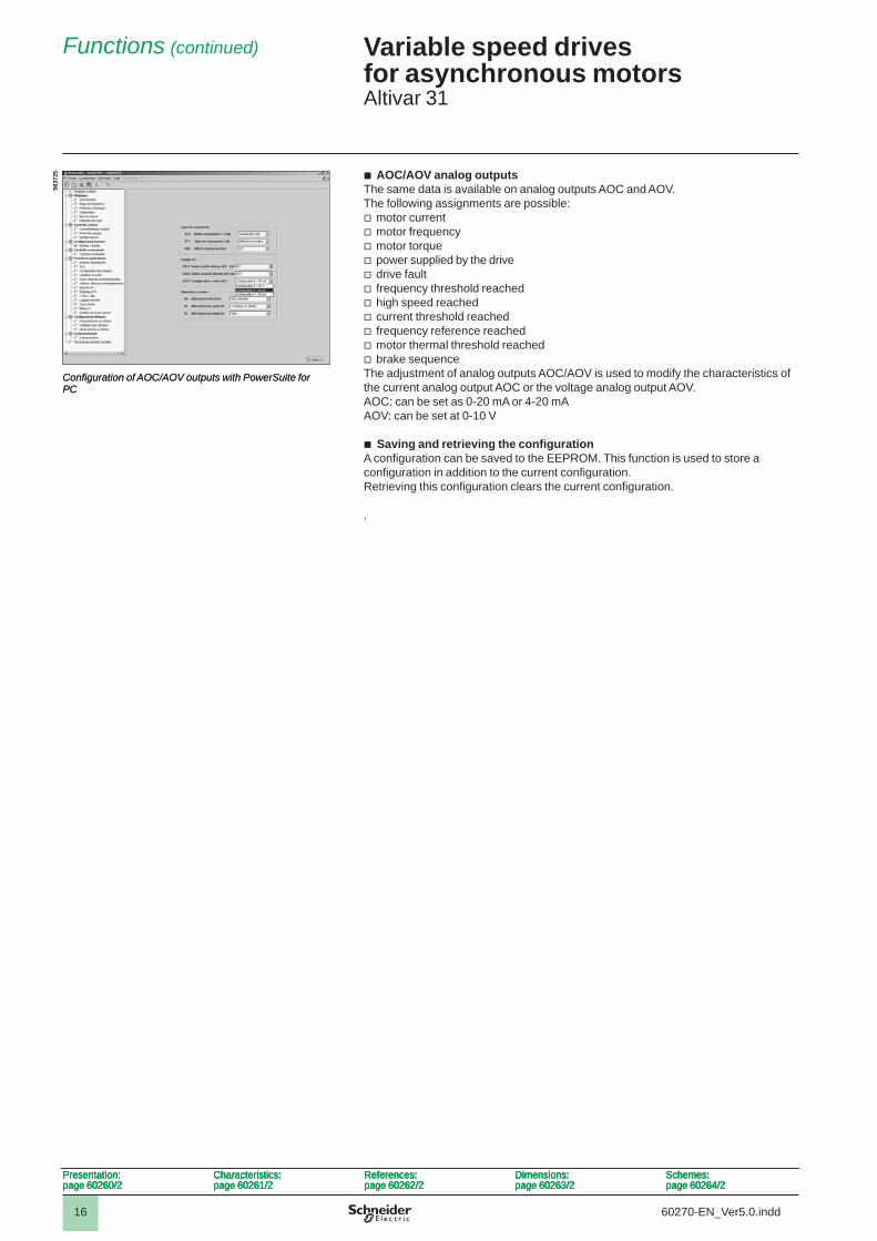
b AOC/AOV analog outputs The same data is available on analog outputs AOC and AOV. The following assignments are possible:v motor currentv motor frequencyv motor torquev power supplied by the drivev drive faultv frequency threshold reachedv high speed reachedv current threshold reachedv frequency reference reachedv motor thermal threshold reachedv brake sequenceThe adjustment of analog outputs AOC/AOV is used to modify the characteristics of the current analog output AOC or the voltage analog output AOV.AOC: can be set as 0-20 mA or 4-20 mAAOV: can be set at 0-10 V
b Saving and retrieving the confi gurationA confi guration can be saved to the EEPROM. This function is used to store a confi guration in addition to the current confi guration.Retrieving this confi guration clears the current confi guration.
.
Confi guration of AOC/AOV outputs with PowerSuite for PC
5637
25
Confi guration of AOC/AOV outputs with PowerSuite for PC
5637
25
Presentation:page 60260/2
Characteristics:page 60261/2
References:page 60262/2
Dimensions:page 60263/2
Schemes:page 60264/2
Presentation:page 60260/2
Characteristics:page 60261/2
References:page 60262/2
Dimensions:page 60263/2
Schemes:page 60264/2
Presentation:page 60260/2
Characteristics:page 60261/2
References:page 60262/2
Dimensions:page 60263/2
Schemes:page 60264/2
Presentation:page 60260/2
Characteristics:page 60261/2
References:page 60262/2
Dimensions:page 60263/2
Schemes:page 60264/2
Functions (continued)2
60270-EN_Ver5.0.indd
1
2
3
4
5
6
7
8
9
10

17
Variable speed drives for asynchronous motors2 Altivar 31
Spooling functions (in textile applications) Function only available with ATV 31ppppT drives
b Traverse ControlFunction for winding reels of thread
The cam rotation speed must follow a precise profi le to ensure a steady, compact, linear reel is obtained.
The function starts when the drive has reached its base reference and the Traverse Control command has been enabled. When the Traverse Control command is no longer enabled, the drive returns to its base reference following the drive ACC or dEC ramp. As soon as this reference is reached, the function stops.
Function parametersUsing certain parameters, it is possible to defi ne the cycle of frequency variations around the base reference, see opposite.
The Traverse Control (thread control) command can be assigned by a logic input or a bit in a Modbus or CANopen control word.
Reel managementVarious parameters are used to manage the reel, such as the reel making time, the decrease in the base reference, reel changes, etc.
Main parameters necessary for reel management:b tbO: time taken to make a reel, in minutes. This parameter is intended to signal the end of winding. When the Traverse Control operating time since the command reaches the value of tbO, the logic output or one of the drive relays changes to state 1, to signal the end of the reel.b dtF: decrease in the base reference. In certain cases, the base reference has to be reduced as the reel increases in size.b rtr: reinitialize Traverse Control. As long as this parameter remains at 1, the Traverse Control function is disabled and the speed is the same as the base reference. This command is used primarily when changing reels.
Traverse Controldrive
Windingdrive
Motor
Thread guide motor Cam
Gearbox
Gearbox
Reel of thread
Main shaft
Thread guide
Thread
Traverse Controldrive
Windingdrive
Motor
Thread guide motor Cam
Gearbox
Gearbox
Reel of thread
Main shaft
Thread guide
Thread
t
t
t
Base reference
LI or bitTraverse Control
command
Run command
Motor speed
ACC ramp
dEC ramp
Start of function
End of function
Bit 15 of word LRS1(Traverse Control active)
t
t
t
t
Base reference
LI or bitTraverse Control
command
Run command
Motor speed
ACC ramp
dEC ramp
Start of function
End of function
Bit 15 of word LRS1(Traverse Control active)
t
t0
tdn: Traverse Control deceleration time, in secondstUP: Traverse Control acceleration time, in secondstrH: Traverse frequency high, in HertztrL: Traverse frequency low, in HertzqSH: Quick step high, in HertzqSL: Quick step low, in Hertz
Defi nition of the cycle of frequency variations around the base reference
tdn tUP
t0
Frequency jump
qSH
trL
trH
qSL
Frequency jump
Base reference
Motor speed
t0
tdn: Traverse Control deceleration time, in secondstUP: Traverse Control acceleration time, in secondstrH: Traverse frequency high, in HertztrL: Traverse frequency low, in HertzqSH: Quick step high, in HertzqSL: Quick step low, in Hertz
Defi nition of the cycle of frequency variations around the base reference
tdn tUP
t0
Frequency jump
qSH
trL
trH
qSL
Frequency jump
Base reference
Motor speed
Presentation:page 60260/2
Characteristics:page 60261/2
References:page 60262/2
Dimensions:page 60263/2
Schemes:page 60264/2
Presentation:page 60260/2
Characteristics:page 60261/2
References:page 60262/2
Dimensions:page 60263/2
Schemes:page 60264/2
Presentation:page 60260/2
Characteristics:page 60261/2
References:page 60262/2
Dimensions:page 60263/2
Schemes:page 60264/2
Presentation:page 60260/2
Characteristics:page 60261/2
References:page 60262/2
Dimensions:page 60263/2
Schemes:page 60264/2
Functions (continued)2
60270-EN_Ver5.0.indd
1
2
3
4
5
6
7
8
9
10
18
Variable speed drives for asynchronous motors2 Altivar 31
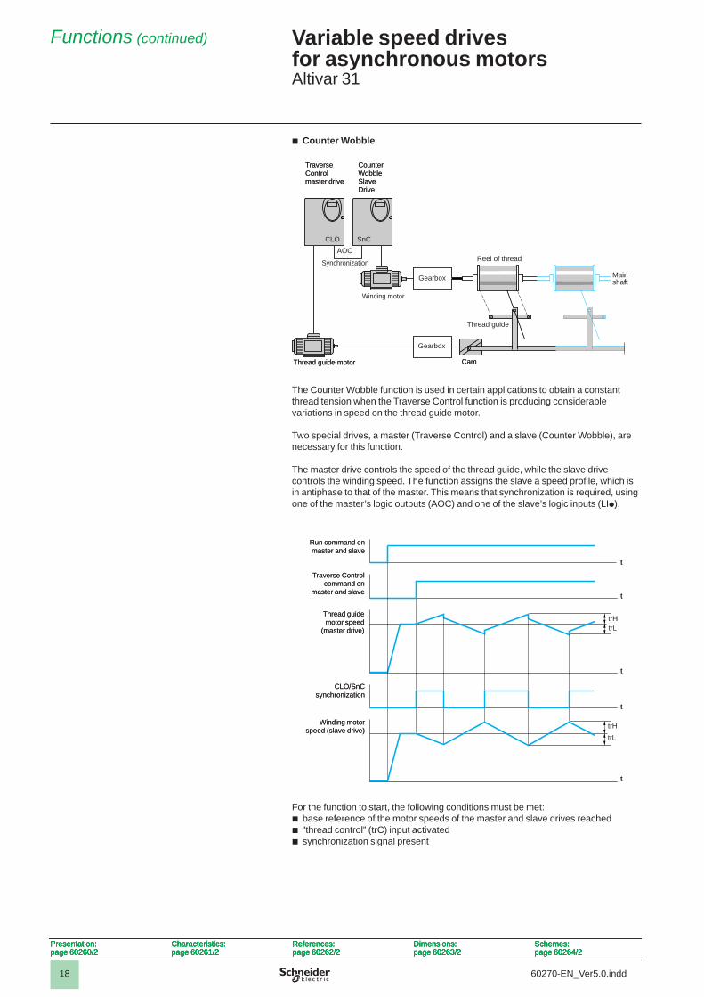
b Counter Wobble
The Counter Wobble function is used in certain applications to obtain a constant thread tension when the Traverse Control function is producing considerable variations in speed on the thread guide motor.
Two special drives, a master (Traverse Control) and a slave (Counter Wobble), are necessary for this function.
The master drive controls the speed of the thread guide, while the slave drive controls the winding speed. The function assigns the slave a speed profi le, which is in antiphase to that of the master. This means that synchronization is required, using one of the master’s logic outputs (AOC) and one of the slave’s logic inputs (LIp).
For the function to start, the following conditions must be met:b base reference of the motor speeds of the master and slave drives reachedb ”thread control” (trC) input activatedb synchronization signal present
TraverseControl master drive
Counter Wobble Slave Drive
Gearbox
Reel of thread
Thread guide
Main
Thread guide motor
Gearbox
Cam
shaft
Winding motor
Synchronization
CLO SnCAOC
TraverseControl master drive
Counter Wobble Slave Drive
Gearbox
Reel of thread
Thread guide
Main
Thread guide motor
Gearbox
Cam
shaft
Winding motor
Synchronization
CLO SnCAOC
Run command onmaster and slave
Traverse Control command on
master and slave
CLO/SnC synchronization
Winding motor speed (slave drive)
Thread guide motor speed
(master drive)
t
t
t
t
t
trHtrL
trLtrH
Run command onmaster and slave
Traverse Control command on
master and slave
CLO/SnC synchronization
Winding motor speed (slave drive)
Thread guide motor speed
(master drive)
t
t
t
t
t
trHtrL
trLtrH
Presentation:page 60260/2
Characteristics:page 60261/2
References:page 60262/2
Dimensions:page 60263/2
Schemes:page 60264/2
Presentation:page 60260/2
Characteristics:page 60261/2
References:page 60262/2
Dimensions:page 60263/2
Schemes:page 60264/2
Presentation:page 60260/2
Characteristics:page 60261/2
References:page 60262/2
Dimensions:page 60263/2
Schemes:page 60264/2
Presentation:page 60260/2
Characteristics:page 60261/2
References:page 60262/2
Dimensions:page 60263/2
Schemes:page 60264/2
Functions (continued)2
60270-EN_Ver5.0.indd
1
2
3
4
5
6
7
8
9
10

19
Variable speed drives for asynchronous motors2 Altivar 31
Function compatibility tableb Confi gurable I/OFunctions which are not listed in this table are fully compatible.Stop functions have priority over run commands.The selection of functions is limited:
- by the number of drive I/O- by the incompatibility of certain functions with one another
Functions Summing inputs
+/- speed Limit switch manage-ment
Preset speeds
PI regulator
Jog operation
Brake sequence
DC injection stop
Fast stop Freewheel stop
Summing inputsA A
+/- speed
Management of limit switch
Preset speedsX A
PI regulator
Jog operationX X
Brake sequence
DC injection stopA
Fast stopA
Freewheel stop X X
Incompatible functions Priority functions (functions which cannot be active at the same time)
Compatible functions X The arrow indicates which function has priority
Not applicable A Example: the Freewheel stop function has priority over the Fast stop function
Presentation:page 60260/2
Characteristics:page 60261/2
References:page 60262/2
Dimensions:page 60263/2
Schemes:page 60264/2
Presentation:page 60260/2
Characteristics:page 60261/2
References:page 60262/2
Dimensions:page 60263/2
Schemes:page 60264/2
Presentation:page 60260/2
Characteristics:page 60261/2
References:page 60262/2
Dimensions:page 60263/2
Schemes:page 60264/2
Presentation:page 60260/2
Characteristics:page 60261/2
References:page 60262/2
Dimensions:page 60263/2
Schemes:page 60264/2
Functions (continued)2
60270-EN_Ver5.0.indd
1
2
3
4
5
6
7
8
9
10