atv310 modbus parameters eav94278 01 - profsector.com · eav94278 2354235 11/2008 altivar 310...
TRANSCRIPT

2354235 11/2008
EAV9
4278
www.schneider-electric.com
Altivar 310Variable speed drives for asynchronous motors
Modbus Communication Manual
06/2014


EAV94278 06/2014 3
Contents
Important Information __________________________________________________________________________________________ 4Before you begin______________________________________________________________________________________________ 5Documentation structure________________________________________________________________________________________ 7Presentation _________________________________________________________________________________________________ 8Connection to RS485 bus_______________________________________________________________________________________ 9Configuration of the Modbus serial port ___________________________________________________________________________ 10IO Scanner configuration parameters_____________________________________________________________________________ 11Modbus Functions ___________________________________________________________________________________________ 13ATV310 state machine ________________________________________________________________________________________ 18Application example __________________________________________________________________________________________ 22Connection to RS485 bus______________________________________________________________________________________ 25
Important Information
NOTICE
Read these instructions carefully, and look at the equipment to become familiar with the device before trying to install, operate, or maintainit. The following special messages may appear throughout this documentation or on the equipment to warn of potential hazards or to callattention to information that clarifies or simplifies a procedure.
PLEASE NOTEThe word "drive" as used in this manual refers to the controller portion of the adjustable speed drive as defined by NEC.
Electrical equipment should be installed, operated, serviced, and maintained only by qualified personnel. No responsibility is assumed bySchneider Electric for any consequences arising out of the use of this material.
© 2014 Schneider Electric. All Rights Reserved
DANGERDANGER indicates an imminently hazardous situation, which, if not avoided, will result in death or serious injury.
WARNINGWARNING indicates a potentially hazardous situation, which, if not avoided, can result in death or serious injury.
CAUTIONCAUTION indicates a potentially hazardous situation, which, if not avoided, can result in minor or moderate injury.
NOTICENOTICE, used without the safety alert symbol, indicates a potentially hazardous situation which, if not avoided, canresult in property damage.
The addition of this symbol to a Danger or Warning safety label indicates that an electrical hazard exists, which will result inpersonal injury if the instructions are not followed.
This is the safety alert symbol. It is used to alert you to potential personal injury hazards. Obey all safety messages that followthis symbol to avoid possible injury or death.
4 EAV94278 06/2014
Before you begin
Read and understand these instructions before performing any procedure with this drive.
DANGERHAZARD OF ELECTRIC SHOCK, EXPLOSION, OR ARC FLASH• Only appropriately trained persons who are familiar with and understand the contents of this manual and all other pertinent product
documentation and who have received safety training to recognize and avoid hazards involved are authorized to work on and with thisdrive system. Installation, adjustment, repair, and maintenance must be performed by qualified personnel.
• The system integrator is responsible for compliance with all local and national electrical code requirements as well as all otherapplicable regulations with respect to grounding of all equipment.
• Many components of the product, including the printed circuit boards, operate with mains voltage. Do not touch. Use only electricallyinsulated tools.
• Do not touch unshielded components or terminals with voltage present.• Motors can generate voltage when the shaft is rotated. Before performing any type of work on the drive system, block the motor shaft
to prevent rotation.• AC voltage can couple voltage to unused conductors in the motor cable. Insulate both ends of unused conductors of the motor cable.• Do not short across the DC bus terminals or the DC bus capacitors or the braking resistor terminals.• Before performing work on the drive system:
- Disconnect all power, including external control power that may be present.- Place a "Do Not Turn On" label on all power switches.- Lock all power switches in the open position.- Wait 15minutes to allow the DC bus capacitors to discharge. The DC bus LED is not an indicator of the absence of DC bus voltage
that can exceed 800Vdc.- Measure the voltage on the DC bus between the DC bus terminals using a properly rated voltmeter to verify that the voltage is
< 42Vdc.- If the DC bus capacitors do not discharge properly, contact your local Schneider Electric representative.
• Install and close all covers before applying voltage.
Failure to follow these instructions will result in death or serious injury.
DANGERUNINTENDED EQUIPMENT OPERATION• Read and understand this manual before installing or operating the ATV310 drive.• Any changes made to the parameter settings must be performed by qualified personnel.
Failure to follow these instructions will result in death or serious injury.
WARNINGDAMAGED DRIVE EQUIPMENTDo not operate or install any drive or drive accessory that appears damaged.
Failure to follow these instructions can result in death, serious injury, or equipment damage.
EAV94278 06/2014 5

Before you begin
a. For USA: Additional information, refer to NEMA ICS 1.1 (latest edition), “Safety Guidelines for the Application, Installation, andMaintenance of Solid State Control” and to NEMA ICS 7.1 (latest edition), “Safety Standards for Construction and Guide for Selection,Installation and Operation of Adjustable Speed Drive Systems.”
WARNINGLOSS OF CONTROL• The designer of any control scheme must consider the potential failure modes of control paths and, for critical control functions,
provide a means to achieve a safe state during and after a path failure. Examples of critical control functions are emergency stop,overtravel stop, power outage, and restart.
• Separate or redundant control paths must be provided for critical control functions.• System control paths may include communication links. Consideration must be given to the implications of unanticipated
transmission delays or failures of the link.• Observe all accident prevention regulations and local safety guidelines. (a)• Each implementation of the product must be individually and thoroughly tested for proper operation before being placed into service.
Failure to follow these instructions can result in death, serious injury or equipment damage.
6 EAV94278 06/2014
Documentation structure
The following Altivar 310 technical documents are available on the Schneider Electric website (www.schneider-electric.com).
ATV310 Quick Start Guide (EAV94272)The Quick Start describes how to wire and configure the drive to start motor quickly and simply for simple applications. This document is delivered with the drive with an Annex (S1A58684) for Short Circuit Current Ratings (SCCR) and branch circuit protection.
ATV310 User manual ( EAV94277)This manual describes how to install, program and operate the drive.
ATV310 Modbus Communication manual (EAV94278)This manual describes the assembly, connection to the bus or network, signaling, diagnostics, and configuration of the communication-specific parameters via the 7 segment LED display.It also describes the communication services of the Modbus protocol.This manual includes all Modbus addresses. It explains the operating mode specific to communication (state chart).
ATV310 Modbus parameters description file ( EAV94279)All the parameters are grouped together in an Excel file with the following data:• Code• Name• Modbus Addresses• Category• Read/write access• Type: signed numerical, unsigned numerical, etc.• Unit• Factory setting• Minimum value• Maximum value• Display on the 7-segment integrated display terminal• Relevant menu• This file offers the option of sorting and arranging the data according to any criterion chosen by the user.
DANGERUNINTENDED EQUIPMENT OPERATION• Read and understand this manual before installing or operating the ATV310 drive.• Any changes made to the parameter settings must be performed by qualified personnel.• The excel file does not describe the behaviour of the parameters. Before any modification, refer to the ATV310 User Manual.
Failure to follow these instructions will result in death or serious injury.
EAV94278 06/2014 7

Presentation
The Modbus socket on the ATV310 can be used for the following functions:
• Configuration• Settings• Control• Monitoring
The ATV310 fc drive supports:• The 2-wire RS485 physical layer• The RTU transmission mode
8 EAV94278 06/2014
Connection to RS485 bus
Connection to ATV310
Connection accessories should be ordered separately (please consult our catalogues).
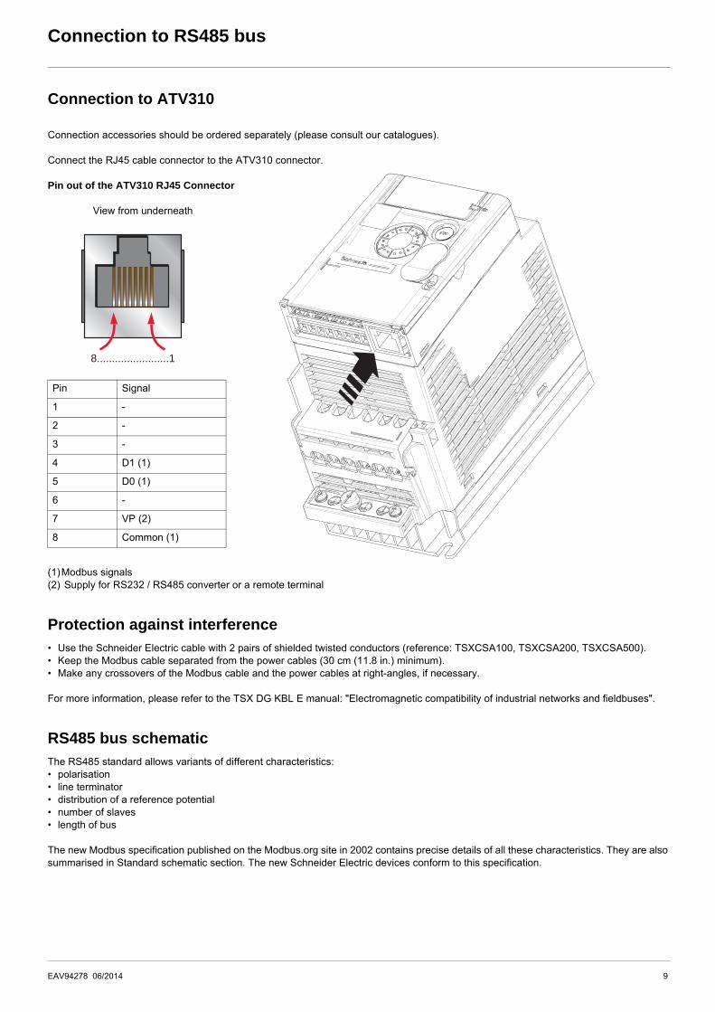
Connect the RJ45 cable connector to the ATV310 connector.
Pin out of the ATV310 RJ45 Connector
View from underneath
(1)Modbus signals(2) Supply for RS232 / RS485 converter or a remote terminal
Protection against interference• Use the Schneider Electric cable with 2 pairs of shielded twisted conductors (reference: TSXCSA100, TSXCSA200, TSXCSA500).• Keep the Modbus cable separated from the power cables (30 cm (11.8 in.) minimum).• Make any crossovers of the Modbus cable and the power cables at right-angles, if necessary.
For more information, please refer to the TSX DG KBL E manual: "Electromagnetic compatibility of industrial networks and fieldbuses".
RS485 bus schematicThe RS485 standard allows variants of different characteristics:• polarisation• line terminator • distribution of a reference potential• number of slaves• length of bus
The new Modbus specification published on the Modbus.org site in 2002 contains precise details of all these characteristics. They are alsosummarised in Standard schematic section. The new Schneider Electric devices conform to this specification.
Pin Signal
1 -
2 -
3 -
4 D1 (1)
5 D0 (1)
6 -
7 VP (2)
8 Common (1)
8........................1
EAV94278 06/2014 9
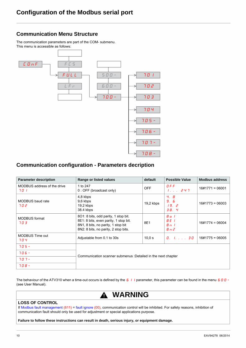
Configuration of the Modbus serial port
Communication Menu StructureThe communication parameters are part of the COM- submenu.This menu is accessible as follows:
Communication configuration - Parameters decription
The behaviour of the ATV310 when a time-out occurs is defined by the 611 parameter, this parameter can be found in the menu 600-
(see User Manual).
Parameter description Range or listed values default Possible Value Modbus address
MODBUS address of the drive701
1 to 2470 : OFF (broadcast only)
OFFOFF
1 ... 24716#1771 = 06001
MODBUS baud rate702
4,8 kbps9,6 kbps19,2 kbps38.4 kbps
19,2 kbps
4.8
9.6
19.2
38.4
16#1773 = 06003
MODBUS format703
8O1: 8 bits, odd parity, 1 stop bit.8E1: 8 bits, even parity, 1 stop bit.8N1, 8 bits, no parity, 1 stop bit8N2: 8 bits, no parity, 2 stop bits.
8E1
8o1
8E1
8n1
8n2
16#1774 = 06004
MODBUS Time out 704
Adjustable from 0.1 to 30s 10,0 s 0.1....30 16#1775 = 06005
705-
Communication scanner submenus :Detailed in the next chapter706-
707-
708-
WARNINGLOSS OF CONTROLIf Modbus fault management (611) = fault ignore (00), communication control will be inhibited. For safety reasons, inhibition of communication fault should only be used for adjustment or special applications purpose.
Failure to follow these instructions can result in death, serious injury, or equipment damage.
COnFCOnF
FULLFULL
FCFCS
LFLFr
500-500-
600-600-
700-700-
701701
702702
703703
704704
705-705-
706-706-
707-707-
708-708-
10 EAV94278 06/2014

IO Scanner configuration parameters
Integrated communication scannerThe communication scanner is useful when used in combination by the Modbus client device with the function "Read/Write Multipleregisters" : 23 (0x17), which provides in a single telegram a read multiple registers and a write multiple registers. The detail of the function23 is described in the supported Modbus functions
Local configuration of the communication scannerThe communication scanner is accessible via the following menus : 700- and 705- 706- submenus.The 4 output variables and the 4 input variables are assigned by means of parameters 706.0 to 706.3and 705.0 to 705.3.An 706 or 705 parameter with a value of zero indicates that the parameter is not active. These 8 parameters are described in the table.
NCA or NMA defines the addresses. All these parameters are Modbus eligible addresses.
Monitoring the communication scannerIt is also possible to monitor the parameters value that have been configured in the communication scanner. This monitored values areaccessible via the following menus : 700- and707- 708- submenu.
The 4 output variable values and the 4 input variable values are located into parameters 708.0 to 708.3and 707.0 to 707.3.
Submenu On the local HMI, it is parameter description Factory setting parameter Modbus address
705- NMA1 (705.0)Source drive address of the 1st input word
Address of ETA=320116#0C81
705.0 address 16#319D = 12701
NMA2 (705.1)Source drive address of the 2nd input word
Address of RFRD=860416#219C
705.1 address 16#319E = 12702
NMA3 (705.2)Source drive address of the 3rd input word
0705.2 address 16#319F = 12703
NMA4 (705.3)Source drive address of the 4th input word
0705.3 address 16#31A0 = 12704
706- NCA1 (706.0)Destination drive address of the 1st output word
Address of CMD=850116#2135
706.0 address 16#31B1 = 12721
NCA2 (706.1)Destination drive address of the 2nd output word
Address of LFRD=860216#219A
706.1 address 16#31B2 = 12722
NCA3 (706.2)Destination drive address of the 3rd output word
0706.2 address 16#31B3 = 12723
NCA4 (706.3)Destination drive address of the 4th output word
0706.3 address 16#31B4 = 12724
Submenu On the local HMI, it is parameter description Factory setting parameter Modbus address
707- NM1 (707.0)Source drive value of the 1st input word
ETA value707.0 address 16#31C5 = 12741
NM2 (707.1)Source drive value of the 2nd input word
RFRD value707.1 address 16#31C6 = 12742
NM3 (707.2)Source drive value of the 3rd input word
0707.2 address 16#31C7 = 12743
NM4 (707.3)Source drive value of the 4th input word
0707.3 address 16#31C8 = 12744
708- NC1 (708.0)Destination drive value of the 1st input word
CMD value708.0 address 16#31D9 = 12761
NC2 (708.1)Destination drive value of the 2nd input word
LFRD value708.1 address 16#31DA = 12762
NC3 (708.2)Destination drive value of the 3rd input word
0708.2 address 16#31DB = 12763
NC4 (708.3)Destination drive value of the 4th input word
0708.3 address 16#31DC = 12764
EAV94278 06/2014 11
IO Scanner configuration parameters
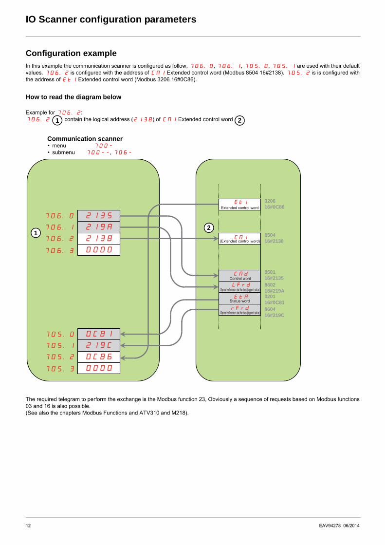
Configuration exampleIn this example the communication scanner is configured as follow, 706.0, 706.1, 705.0, 705.1 are used with their defaultvalues. 706.2 is configured with the address of CMI Extended control word (Modbus 8504 16#2138). 705.2 is is configured withthe address of EtI Extended control word (Modbus 3206 16#0C86).
How to read the diagram below
Example for 706.2:706.2 contain the logical address (2138) of CMI Extended control word
The required telegram to perform the exchange is the Modbus function 23, Obviously a sequence of requests based on Modbus functions03 and 16 is also possible.(See also the chapters Modbus Functions and ATV310 and M218).
Communication scanner• menu 700-
• submenu 700--, 706-
1 2
21352135706.0706.0
706.1706.1
706.2706.2
706.3706.3
219A219A
21382138
00000000
0C810C81705.0705.0
705.1705.1
705.2705.2
705.3705.3
219C219C
0C860C86
00000000
320116#0C81
EtAEtA
860416#219C
rFrdrFrd
EtIEtI
850416#2138
850116#2135
CMdCMd
860216#219A
LFrdLFrd
CMICMI
320616#0C86Extended control word
(Extended control word)
Control word
Speed reference via the bus (signed value)
Speed reference via the bus (signed value)
Status word
12
12 EAV94278 06/2014

Modbus Functions
Modbus ProtocolThe transmission mode used is RTU mode. The frame contains no message header byte, nor end of message bytes. It is defined as follows:
The data is transmitted in binary code.CRC16: cyclical redundancy check.The end of the frame is detected on a silence greater than or equal to 3 characters.
PrincipleThe Modbus protocol is a master-slave protocol.
Direct slave-to-slave communications are not possible.
For slave-to-slave communication, the application software must therefore be designed to interrogate a slave and send back data receivedto the other slave.
Two types of dialogue are possible between master and slaves:• the master sends a request to a slave and waits for its response• the master sends a request to all slaves without waiting for a response (broadcasting principle)
Addresses• The drive Modbus address can be configured from 1 to 247.• Address 0 coded in a request sent by the master is reserved for broadcasting. ATV310 drives take account of the request, but do not
respond to it.
Supported Modbus functionsThe ATV310 supports the following Modbus functions.
Slave address
Request code Data CRC16
Master Only one device can transmit on the line at any time.The master manages the exchanges and only it can takethe initiative.It interrogates each of the slaves in succession.No slave can send a message unless it is invited to do so.The master repeats the question when there is an incorrectexchange, and declares the interrogated slave absent if noresponse is received within a given time period. If a slave does not understand a message, it sends anexception response to the master. The master may or maynot repeat the request.
Slave i Slave j Slave k
Function name Code Description Remarks
Read holding registers 0316#03
Read N output words Max PDU length : 63 words
Write one output word 0616#06
Write one output word
Write multiple registers 1616#10
Write N output word Max PDU length : 61 words
Read/write Multiple registers 2316#17
Read/write multiple registers Max PDU length : 4 words (W), 4 words (R)
(Sub-function)Read device Identification
43/1416#2B16#OE
Encapsulated interface transport/ Read device identification
EAV94278 06/2014 13

Modbus Functions
The following paragraphs describes each supported function.
Read Holding registers
Request
Response
*N: Quantity of Registers
Error
ExampleNote: Hi = high order byte, Lo = low order byte.
This function can be used to read all ATV310 words, both input words and output words.
Request
Response
Example: read 4 words W3102 to W3105 (16#0C1E to 16#0C21) in slave 2, using function 3, where:
• 315 = Switching frequency = 4 kHz (W3102 = 16#0028)• 308 = Maximum output frequency = 60 Hz (W3103 = 16#0258)• 512.2 = High speed = 50 Hz (W3104 = 16#01F4)• LSP = Low speed = 0 Hz (W3105 = 16#0000)
Function code 1 Byte 0x03
Starting Address 2 Bytes 0x0000 to 0xFFFF
Quantity of Registers 2 Bytes 1 to 63 (0x 3F)
Function code 1 Byte 0x03
Byte count 1 Byte 2 x N*
Register value N* x 2 Bytes
Error code 1 Byte 0x83
Exception code 1 Byte 01 or 02 or 03 or 04 (see details on page 17)
Slaveno.
03 No. of first word Number of words CRC16
Hi Lo Hi Lo Lo Hi
1 byte 1 byte 2 bytes 2 bytes 2 bytes
Slaveno.
03 Number of bytes read
First word value ------- Last word value CRC16
Hi Lo Hi Lo Lo Hi
1 byte 1 byte 1 byte 2 bytes 2 bytes 2 bytes
Request 02 03 0C1E 0004 276C
Response 02 03 08 0028 0258 01F4 0000 52B0
Value of: W3102 W3103 W3104 W3105
Parameters: 315 308 512.2 512.0
14 EAV94278 06/2014
Modbus Functions
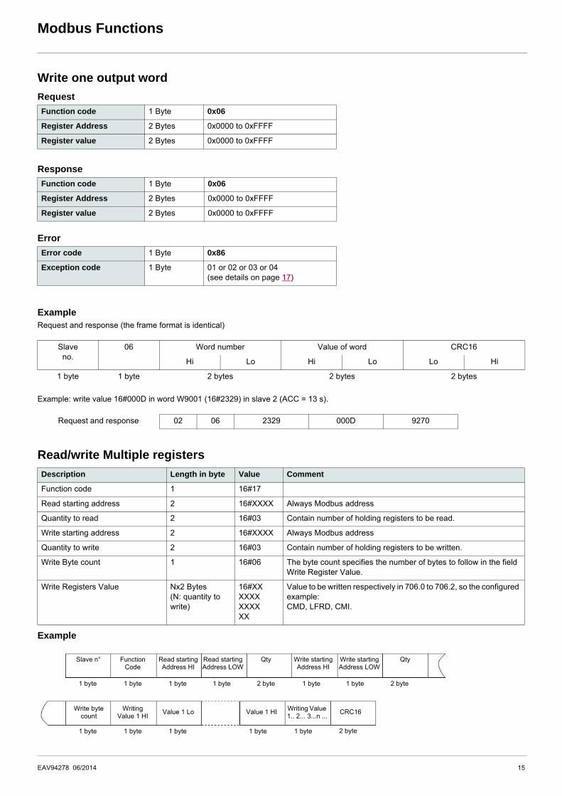
Write one output word
Request
Response
Error
ExampleRequest and response (the frame format is identical)
Example: write value 16#000D in word W9001 (16#2329) in slave 2 (ACC = 13 s).
Read/write Multiple registers
Example
Function code 1 Byte 0x06
Register Address 2 Bytes 0x0000 to 0xFFFF
Register value 2 Bytes 0x0000 to 0xFFFF
Function code 1 Byte 0x06
Register Address 2 Bytes 0x0000 to 0xFFFF
Register value 2 Bytes 0x0000 to 0xFFFF
Error code 1 Byte 0x86
Exception code 1 Byte 01 or 02 or 03 or 04 (see details on page 17)
Slaveno.
06 Word number Value of word CRC16
Hi Lo Hi Lo Lo Hi
1 byte 1 byte 2 bytes 2 bytes 2 bytes
Request and response 02 06 2329 000D 9270
Description Length in byte Value Comment
Function code 1 16#17
Read starting address 2 16#XXXX Always Modbus address
Quantity to read 2 16#03 Contain number of holding registers to be read.
Write starting address 2 16#XXXX Always Modbus address
Quantity to write 2 16#03 Contain number of holding registers to be written.
Write Byte count 1 16#06 The byte count specifies the number of bytes to follow in the field Write Register Value.
Write Registers Value Nx2 Bytes(N: quantity to write)
16#XXXXXXXXXXXX
Value to be written respectively in 706.0 to 706.2, so the configured example:CMD, LFRD, CMI.
Slave n° FunctionCode
Read startingAddress HI
Read startingAddress LOW
Qty Write startingAddress HI
Write startingAddress LOW
Qty
2 byte 1 byte 1 byte 2 byte1 byte1 byte1 byte1 byte
1 byte 1 byte1 byte1 byte1 byte
Write bytecount
Writing Value 1 HI
Value 1 Lo Value 1 HI Writing Value 1.. 2... 3...n ...
CRC16
2 byte
EAV94278 06/2014 15
Modbus Functions
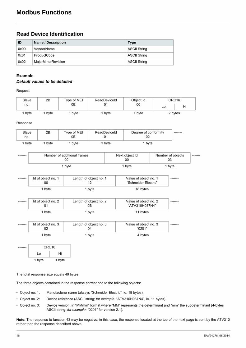
Read Device Identification
Example
Default values to be detailed
Request
Response
The total response size equals 49 bytes
The three objects contained in the response correspond to the following objects:
Note: The response to function 43 may be negative; in this case, the response located at the top of the next page is sent by the ATV310rather than the response described above.
ID Name / Description Type
0x00 VendorName ASCII String
0x01 ProductCode ASCII String
0x02 MajorMinorRevision ASCII String
Slaveno.
2B Type of MEI0E
ReadDeviceId01
Object Id00
CRC16
Lo Hi
1 byte 1 byte 1 byte 1 byte 1 byte 2 bytes
Slaveno.
2B Type of MEI0E
ReadDeviceId01
Degree of conformity02
-------
1 byte 1 byte 1 byte 1 byte 1 byte
------- Number of additional frames00
Next object Id00
Number of objects03
-------
1 byte 1 byte 1 byte
------- Id of object no. 100
Length of object no. 112
Value of object no. 1“Schneider Electric”
-------
1 byte 1 byte 18 bytes
------- Id of object no. 201
Length of object no. 20B
Value of object no. 2“ATV310H037N4”
-------
1 byte 1 byte 11 bytes
------- Id of object no. 302
Length of object no. 304
Value of object no. 3“0201”
-------
1 byte 1 byte 04 bytes
------- CRC16
Lo Hi
1 byte 1 byte
• Object no. 1: Manufacturer name (always “Schneider Electric”, ie. 18 bytes).
• Object no. 2: Device reference (ASCII string; for example: “ATV310H037N4”, ie. 11 bytes).
• Object no. 3: Device version, in “MMmm” format where “MM” represents the determinant and “mm” the subdeterminant (4-bytes ASCII string; for example: “0201” for version 2.1).
16 EAV94278 06/2014
Modbus Functions
Error management
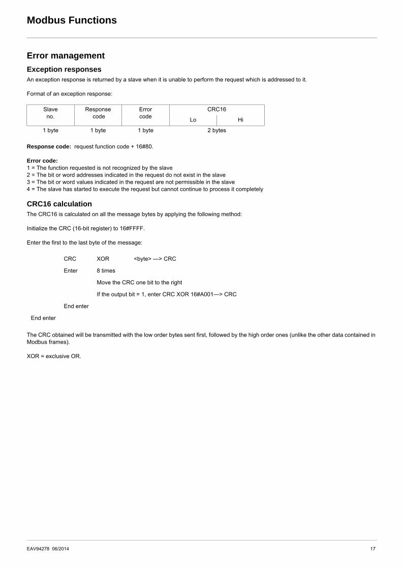
Exception responsesAn exception response is returned by a slave when it is unable to perform the request which is addressed to it.
Format of an exception response:
Response code: request function code + 16#80.
Error code: 1 = The function requested is not recognized by the slave2 = The bit or word addresses indicated in the request do not exist in the slave3 = The bit or word values indicated in the request are not permissible in the slave4 = The slave has started to execute the request but cannot continue to process it completely
CRC16 calculationThe CRC16 is calculated on all the message bytes by applying the following method:
Initialize the CRC (16-bit register) to 16#FFFF.
Enter the first to the last byte of the message:
The CRC obtained will be transmitted with the low order bytes sent first, followed by the high order ones (unlike the other data contained inModbus frames).
XOR = exclusive OR.
Slaveno.
Response code
Errorcode
CRC16
Lo Hi
1 byte 1 byte 1 byte 2 bytes
CRC XOR <byte> —> CRC
Enter 8 times
Move the CRC one bit to the right
If the output bit = 1, enter CRC XOR 16#A001—> CRC
End enter
End enter
EAV94278 06/2014 17
ATV310 state machine
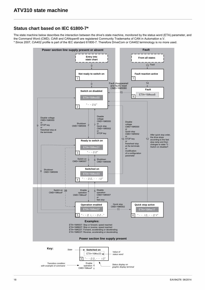
Status chart based on IEC 61800-7*The state machine below describes the interaction between the drive's state machine, monitored by the status word (ETA) parameter, andthe Command Word (CMD). CiA® and CANopen® are registered Community Trademarks of CAN in Automation e.V.*:Since 2007, CiA402 profile is part of the IEC standard 61800-7. Therefore DriveCom or CiA402 terminology is no more used.
“--00,--10”
“--00,--10”
“--00”
“--06”
“--10,--04”“--01,--02...”
FaultPower section line supply present or absent
Power section line supply present
Transition conditionwith example of command
Value ofstatus word
Status display ongraphic display terminal
StateKey:
Examples:ETA=16#0637: Stop or forward, speed reachedETA=16#8637: Stop or reverse, speed reachedETA=16#0237: Forward, accelerating or deceleratingETA=16#8237: Reverse, accelerating or decelerating
Enableoperation
CMD=16#xxxF
Switched on
Ready to switch on
Switched on
Operation enabled
Enableoperation
CMD=16#xxxF
DisableoperationCMD=16#0007orfast stop
Quick stopCMD=16#0002
Quick stop active
Switch onCMD=16#xxxF
ShutdownCMD=16#0006
Switch onCMD=16#0007
ShutdownCMD=16#0006
DisablevoltageCMD=16#0000orQuick stopCMD=16#0002 orSTOP keyorfreewheel stopat the terminalsormodificationof a configurationparameter
DisablevoltageCMD=16#0000orQuick stopCMD=16#0002 orSTOP key
ShutdownCMD=16#0006
Disable voltageCMD=16#0000orSTOP keyorfreewheel stop at the terminals
Switch on disabled
Fault disappeared and faults resetCMD=16#0080
Not ready to switch on
Entry intostate chart
Fault reaction active
From all states
Fault
Fault
After quick stop order, the drive stops according to the fast stop ramp and then changes to state "2 - Switch on disabled".
18 EAV94278 06/2014
ATV310 state machine
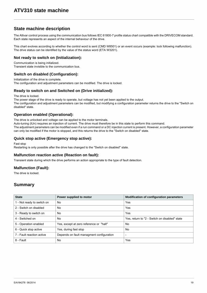
State machine descriptionThe Altivar control process using the communication bus follows IEC 61800-7 profile status chart compatible with the DRIVECOM standard.Each state represents an aspect of the internal behaviour of the drive.
This chart evolves according to whether the control word is sent (CMD W8501) or an event occurs (example: lock following malfunction).The drive status can be identified by the value of the status word (ETA W3201).
Not ready to switch on (Initialization):Communication is being initialized.Transient state invisible to the communication bus.
Switch on disabled (Configuration):Initialization of the drive is complete.The configuration and adjustment parameters can be modified. The drive is locked.
Ready to switch on and Switched on (Drive initialized):The drive is locked.The power stage of the drive is ready to operate, but voltage has not yet been applied to the output.The configuration and adjustment parameters can be modified, but modifying a configuration parameter returns the drive to the "Switch ondisabled" state.
Operation enabled (Operational):The drive is unlocked and voltage can be applied to the motor terminals.Auto-tuning (tUn) requires an injection of current. The drive must therefore be in this state to perform this command.The adjustment parameters can be modified even if a run command or a DC injection current is present. However, a configuration parametercan only be modified if the motor is stopped, and this returns the drive to the "Switch on disabled" state.
Quick stop active (Emergency stop active):Fast stopRestarting is only possible after the drive has changed to the "Switch on disabled" state.
Malfunction reaction active (Reaction on fault):Transient state during which the drive performs an action appropriate to the type of fault detection.
Malfunction (Fault):The drive is locked.
Summary
State Power supplied to motor Modification of configuration parameters
1 - Not ready to switch on No Yes
2 - Switch on disabled No Yes
3 - Ready to switch on No Yes
4 - Switched on No Yes, return to "2 - Switch on disabled" state
5 - Operation enabled Yes, except at zero reference or "halt" No
6 - Quick stop active Yes, during fast stop No
7 - Fault reaction active Depends on fault managment configuration -
8 - Fault No Yes
EAV94278 06/2014 19
ATV310 state machine
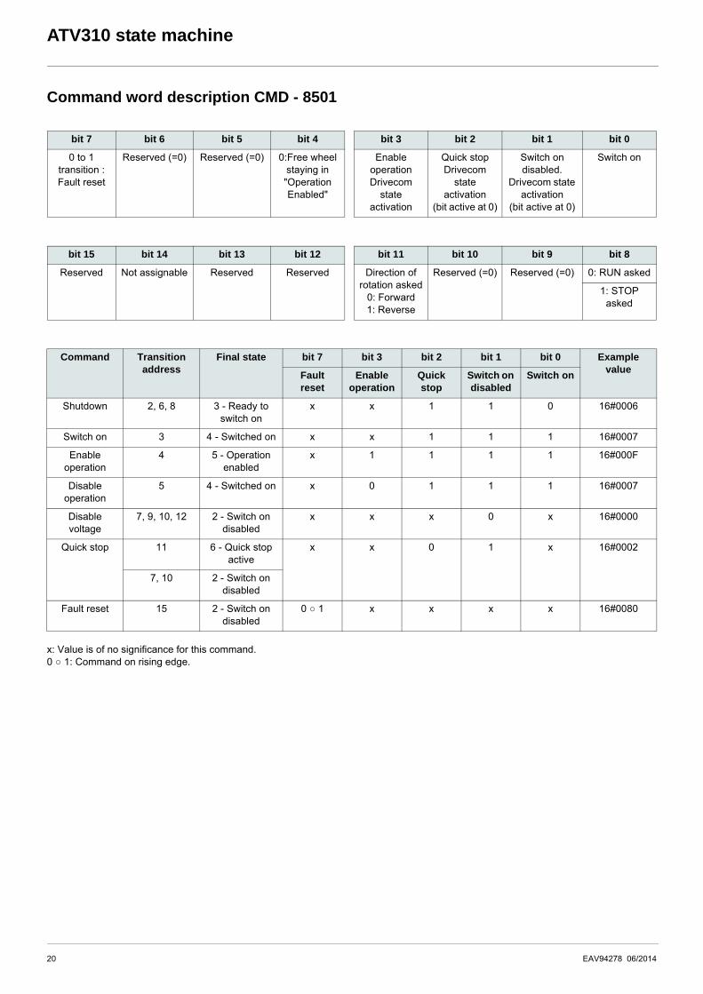
Command word description CMD - 8501
x: Value is of no significance for this command.0 ○ 1: Command on rising edge.
bit 7 bit 6 bit 5 bit 4 bit 3 bit 2 bit 1 bit 0
0 to 1 transition : Fault reset
Reserved (=0) Reserved (=0) 0:Free wheel staying in "Operation Enabled"
Enable operationDrivecom
state activation
Quick stopDrivecom
state activation
(bit active at 0)
Switch on disabled.
Drivecom state activation
(bit active at 0)
Switch on
bit 15 bit 14 bit 13 bit 12 bit 11 bit 10 bit 9 bit 8
Reserved Not assignable Reserved Reserved Direction of rotation asked
0: Forward1: Reverse
Reserved (=0) Reserved (=0) 0: RUN asked
1: STOP asked
Command Transition address
Final state bit 7 bit 3 bit 2 bit 1 bit 0 Example value
Fault reset
Enable operation
Quick stop
Switch on disabled
Switch on
Shutdown 2, 6, 8 3 - Ready to switch on
x x 1 1 0 16#0006
Switch on 3 4 - Switched on x x 1 1 1 16#0007
Enable operation
4 5 - Operation enabled
x 1 1 1 1 16#000F
Disable operation
5 4 - Switched on x 0 1 1 1 16#0007
Disable voltage
7, 9, 10, 12 2 - Switch on disabled
x x x 0 x 16#0000
Quick stop 11 6 - Quick stop active
x x 0 1 x 16#0002
7, 10 2 - Switch on disabled
Fault reset 15 2 - Switch on disabled
0 ○ 1 x x x x 16#0080
20 EAV94278 06/2014
ATV310 state machine
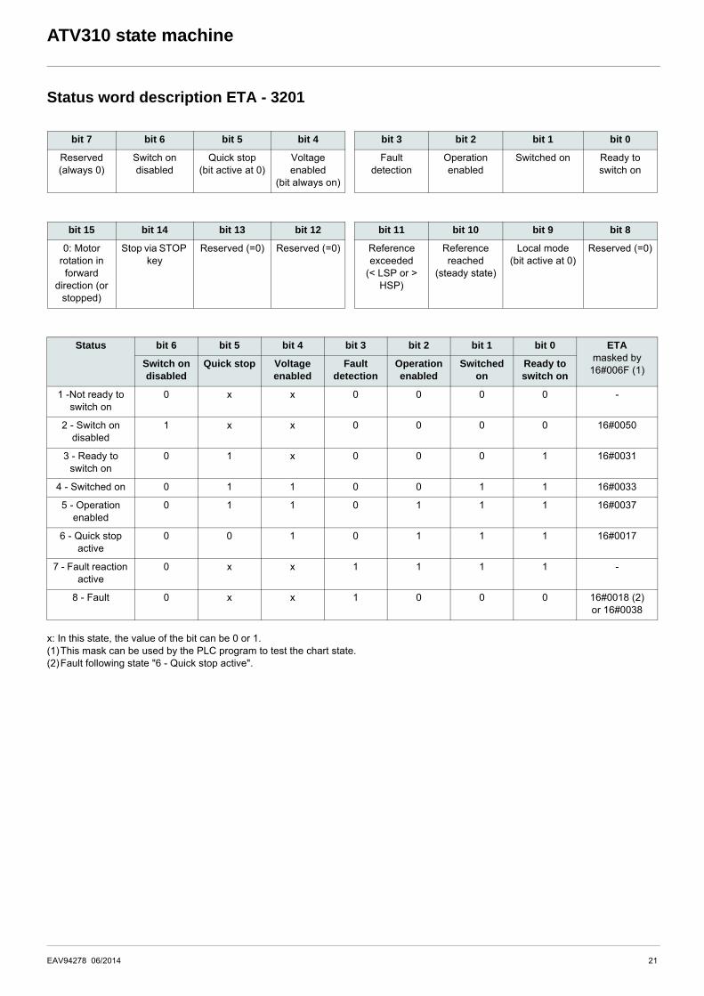
Status word description ETA - 3201
x: In this state, the value of the bit can be 0 or 1.(1)This mask can be used by the PLC program to test the chart state.(2)Fault following state "6 - Quick stop active".
bit 7 bit 6 bit 5 bit 4 bit 3 bit 2 bit 1 bit 0
Reserved (always 0)
Switch on disabled
Quick stop(bit active at 0)
Voltage enabled
(bit always on)
Fault detection
Operation enabled
Switched on Ready to switch on
bit 15 bit 14 bit 13 bit 12 bit 11 bit 10 bit 9 bit 8
0: Motor rotation in forward
direction (or stopped)
Stop via STOP key
Reserved (=0) Reserved (=0) Reference exceeded
(< LSP or > HSP)
Reference reached
(steady state)
Local mode(bit active at 0)
Reserved (=0)
Status bit 6 bit 5 bit 4 bit 3 bit 2 bit 1 bit 0 ETAmasked by
16#006F (1)Switch on disabled
Quick stop Voltage enabled
Fault detection
Operation enabled
Switched on
Ready to switch on
1 -Not ready to switch on
0 x x 0 0 0 0 -
2 - Switch on disabled
1 x x 0 0 0 0 16#0050
3 - Ready to switch on
0 1 x 0 0 0 1 16#0031
4 - Switched on 0 1 1 0 0 1 1 16#0033
5 - Operation enabled
0 1 1 0 1 1 1 16#0037
6 - Quick stop active
0 0 1 0 1 1 1 16#0017
7 - Fault reaction active
0 x x 1 1 1 1 -
8 - Fault 0 x x 1 0 0 0 16#0018 (2)or 16#0038
EAV94278 06/2014 21
Application example
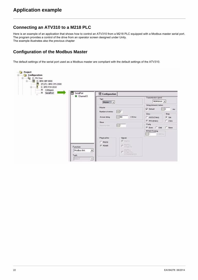
Connecting an ATV310 to a M218 PLCHere is an example of an application that shows how to control an ATV310 from a M218 PLC equipped with a Modbus master serial port.The program provides a control of the drive from an operator screen designed under Unity.The example illustrates also the previous chapter
Configuration of the Modbus Master
The default settings of the serial port used as a Modbus master are compliant with the default settings of the ATV310.
22 EAV94278 06/2014
Application example
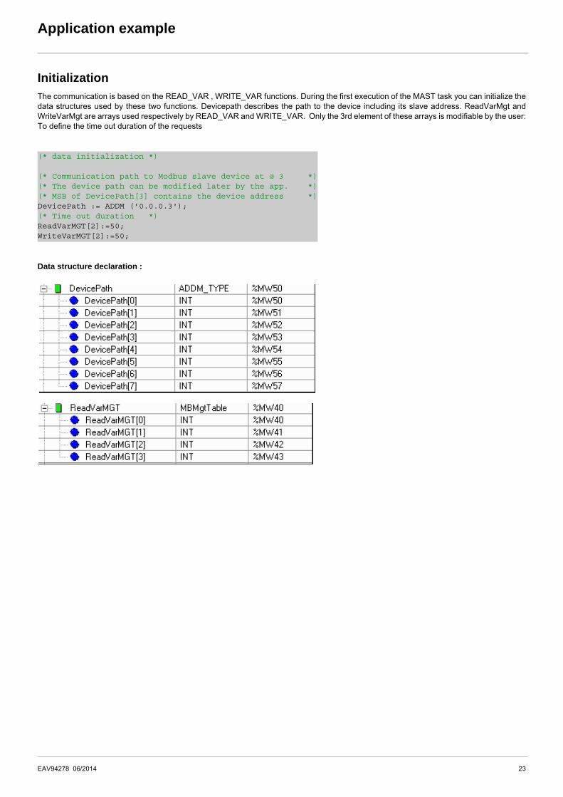
InitializationThe communication is based on the READ_VAR , WRITE_VAR functions. During the first execution of the MAST task you can initialize thedata structures used by these two functions. Devicepath describes the path to the device including its slave address. ReadVarMgt andWriteVarMgt are arrays used respectively by READ_VAR and WRITE_VAR. Only the 3rd element of these arrays is modifiable by the user:To define the time out duration of the requests
Data structure declaration :
(* data initialization *)
(* Communication path to Modbus slave device at @ 3 *)(* The device path can be modified later by the app. *)(* MSB of DevicePath[3] contains the device address *)DevicePath := ADDM ('0.0.0.3');(* Time out duration *)ReadVarMGT[2]:=50;WriteVarMGT[2]:=50;
EAV94278 06/2014 23
Application example
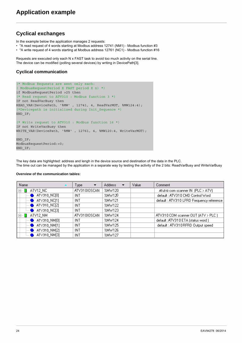
Cyclical exchangesIn the example below the application manages 2 requests:• "A read request of 4 words starting at Modbus address 12741 (NM1) - Modbus function #3• "A write request of 4 words starting at Modbus address 12761 (NC1) - Modbus function #16
Requests are executed only each N x FAST task to avoid too much activity on the serial line. The device can be modified (polling several devices) by writing in DevicePath[3].
Cyclical communication
The key data are highlighted: address and lengh in the device source and destination of the data in the PLC.The time out can be managed by the application in a separate way by testing the activity of the 2 bits: ReadVarBusy and WriteVarBusy
Overview of the communication tables:
(* Modbus Requests are sent only each: ( ModbusRequestPeriod X FAST period X n) *) if ModbusRequestPeriod >25 then(* Read request to ATV310 : Modbus function 3 *)IF not ReadVarBusy thenREAD_VAR(DevicePath, '%MW' , 12741, 4, ReadVarMGT, %MW124:4);(*Devicepath is initialized during Init_Sequence *)END_IF;
(* Write request to ATV310 : Modbus function 16 *)IF not WriteVarBusy thenWRITE_VAR(DevicePath, '%MW' , 12761, 4, %MW120:4, WriteVarMGT); END_IF;ModbusRequestPeriod:=0;END_IF;
24 EAV94278 06/2014
Connection to RS485 bus
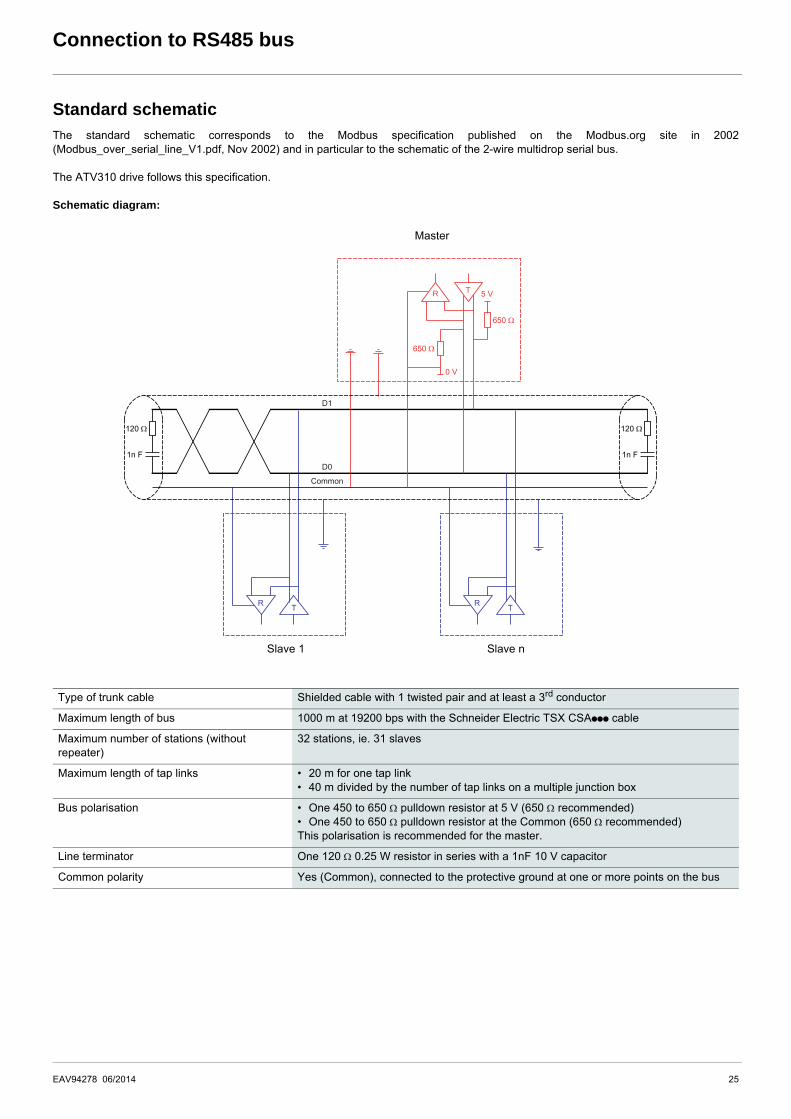
Standard schematicThe standard schematic corresponds to the Modbus specification published on the Modbus.org site in 2002(Modbus_over_serial_line_V1.pdf, Nov 2002) and in particular to the schematic of the 2-wire multidrop serial bus.
The ATV310 drive follows this specification.
Schematic diagram:
Master
Slave 1 Slave n
Type of trunk cable Shielded cable with 1 twisted pair and at least a 3rd conductor
Maximum length of bus 1000 m at 19200 bps with the Schneider Electric TSX CSAppp cable
Maximum number of stations (without repeater)
32 stations, ie. 31 slaves
Maximum length of tap links • 20 m for one tap link• 40 m divided by the number of tap links on a multiple junction box
Bus polarisation • One 450 to 650 pulldown resistor at 5 V (650 recommended)• One 450 to 650 pulldown resistor at the Common (650 recommended)This polarisation is recommended for the master.
Line terminator One 120 0.25 W resistor in series with a 1nF 10 V capacitor
Common polarity Yes (Common), connected to the protective ground at one or more points on the bus
1n F
650
650
120
1n F
120
5 V
0 V
TR
TR
TR
D1
Common
D0
EAV94278 06/2014 25

26 EAV94278 06/2014


EAV94278
ATV310_Modbus_EN_EAV94278_01
06/2014