audio enhancement product instruction manual › ... ›...
TRANSCRIPT

Audio Enhancement Product Instruction Manual

Table of Contents
Introduction……………………………………………….
Safety Instructions……………………………………….
Explanation of Symbols………………………………….
Product Specifications……………………………………
Operating 100W Controls………………………………..
Operating 50W Controls...……………………………….
Operating 20W Controls..………………………………..
Operating RC-07 Controls…………………………….
Operating Sensor Controls…..…………………………...
Operating Handheld Mic Controls……………………….
Operating Teacher Mic Controls…………………………
Operating Charger Controls………………………………
Operating Procedure ……………………………………..
Changing the Battery……………………………………..
Controlling the Volume…………………………………..
Using the Microphone as a Transmitter………………….
Installation………………………………………………..
About the Coaxial Cables………………………………...
Setting the Frequency…………………………………….
Setting the Aux Mute……………………………………..
Setting the PA Aux Mute…………………………………
Setting the EMG Aux Mute………………………………
About External Control…………………………………...
Precautions for Installation……………………………….
Installing the Bracket……………………………………..
Fuse Part Numbers …………………………………...…..
Teacher’s Check List……………………………………..
Troubleshooting…………………………………………..
Repair Form………………………………………………
Notes……………………………………………………...
Warranty Information…………………………………….
Page 3-4
Page 5
Page 6
Page 7
Page 8-9
Page 10-11
Page 12-13
Page 14-15
Page 16-17
Page 18
Page 19-20
Page 21
Page 22
Page 23-24
Page 25
Page 26
Page 27-35
Page 36-37
Page 38
Page 39
Page 40-41
Page 42-43
Page 44
Page 45
Page 46-49
Page 50
Page 51
Page 52-53
Page 54
Page 55-56
Page 57

3 AudioEnhancement.com
(800) 383-9362
Students helping Students
AUDIO ENHANCEMENT has been creating technologically ad-vanced products that exceed expectations for over 25 years. They are designed by caring professionals for those who teach and those who will become the future leaders of America. Se-lecting the infrared classroom sound amplification system is the most important step to improve the learning environment. Your infrared classroom system represents a breakthrough in classroom amplification. It assures you the clarity and interfer-ence free performance you expect; trouble free performance with unlimited numbers of systems used in the same building. Please read through this manual before installing and using the IR systems and refer to it often to become familiar with class-room sound amplification systems. Our staff is available to an-swer any questions that may arise; call 1-800-383-9362.
Introduction

AudioEnhancement.com (800) 383-9362 4
When asked to rank the importance of nine different types of equipment used in classroom instruction, 34% of the teachers in general education ranked class-room amplification most important , even over the overhead projector, which came in second at 18% and the computer at 16%! (1) 45% of the school day is spent by children engaged in listening activities. (2) 90% of a very young child’s knowledge is attributed to incidental reception of a conversation around them. (3) 1. Allen, L. (1993). Promoting the usefulness of classroom amplification equipment. Educational Audiology Monograph 3, 32-34. 2. Berg, F.S. (1987). Facilitating classroom listening: A handbook for teachers of normal and hard of hearing students. Boston: College-Hill Press/Little, Brown. 3. Flexer, Carol (1993). “Classroom Management of Children with Hearing Loss: Preferential Seating is NOT enough” presentation. San Francisco, CA 8/14/93.
Introduction

Warning:
• To reduce the risk of fire or electric shock, do not expose this re-ceiver/amplifier to rain or moisture.
• The apparatus should not be exposed to dripping or splashing and that not objects filled with liquids, such as vases, should be placed on the apparatus.
AudioEnhancement.com (800) 383-9362 5
Safety Instructions
1) Read these instructions. 2) Keep these instructions. 3) Heed all warnings. 4) Follow all instructions. 5) Do not use this apparatus near water. 6) Clean only with dry cloth. 7) Do not block any ventilation openings. Install in accordance with the manufacturer‘s instructions. 8) Do not use near any heat sources such as radiators, heat registers, stoves, or other apparatus (including amplifiers) that produce heat. 9) Do not defeat the safety purpose of the polarized or grounding-type plug. A polar-ized plug has two blades with one wider than the other. A grounding-type plug has two blades and a third grounding prong. The wide blade or the third prong are pro-vided for your safety. If the provided plug does not fit into your outlet, consult an elec-trician for replacement of the obsolete outlet. 10) Protect the power cord from being walked on or pinched particularly at plugs, con-venience receptacles and the points where they exit from the apparatus. 11) Only use attachments/accessories specified by the manufacturer. 12) Use only with the cart, stand, tripod, bracket, or table specified by the manufac-turer, or sold with the apparatus. When a cart is used, use caution when moving the cart/apparatus combination to avoid injury from tip-overs. 13) Unplug this apparatus during lightning storms or when unused for long periods of time. 14) Refer all servicing to qualified service personnel. Servicing is required when the apparatus has been damaged in any way, such as power-supply cord or plug is dam-aged, liquid has been spilled or objects fallen into the apparatus, the apparatus has been exposed to rain or moisture, does not operate normally, or has been dropped.

120 Vac. A.C. Power Only
50 to 60 Hz Rated Mains Frequency
AudioEnhancement.com (800) 383-9362 6
Explanation of Symbols
The date or a dating code not exceeding any three consecutive months of manufacture. The dating code shall be in an established alphanu-meric code affirmed by the manufacturer. The coding system shall have a minimum 10 year repetition cycle.
CAUTION - These servicing instructions are for use by qualified service personnel only. To reduce the risk of electric shock, do not perform any servicing other than that contained in the operating instructions unless you are qualified to do so.

AudioEnhancement.com (800) 383-9362
Transmitter’s Wireless transmitter Sub-carrier frequencies 4 selectable frequencies from 2.0 MHz to 4.0 MHz Intergraded microphone uni-directional electrets Mic gain adjustment Max to -50dB Battery type 2-"AA" alkaline (2 x 1.5V) 2-"AA" rechargeable Ni-MH (2 x 1.2V) Battery life 6 to 8 hours Size 4.0" H x 6.0" W x 2.0" D Handheld transmitter Sub-carrier frequencies 4 selectable frequencies from 2.0 MHz to 4.0 MHz Audio distortion < 1.0% (±15kHz deviation @ 1kHz) Microphone element type uni-directional, dynamic Battery type 2-"AA" alkaline (2 x 1.5V) 2-"AA" rechargeable Ni-MH (2 x 1.2V) Battery life (100mA drain)> 15 hours w/alkaline batteries—low. Size 9.5" x 1.5" Weight 9.1oz (258g) w/alkaline batteries)
External sensor Cable length 50’' Power powered by receiver Size 4.5” Dia x 2.25” D Weight 5.6 oz (113.4g) Mounting included metal bracket
7
Specifications

8 AudioEnhancement.com
(800) 383-9362
(1) Power switch Turns the power on/off. (2) Power indicator Lights "green" when the power is turned ON. (3) Infrared Microphone Volume Control [Teacher 1 to 4] This control is used to adjust the level of the infrared microphones. (4) Infrared Signal Indicator [Teacher 1 to 4] Lights "green" when the infrared wireless receiver is receiving a signal. (5) Auxiliary Input volume [TV/DVD, CD, COMPUTER, and MP3] This Control adjusts the volume of the auxiliary inputs connected to the input terminals (11). (6) Master volume Adjusts overall level of the system. (7) Equalizer [LOW, MID, HIGH] The 3-Band Equalizer allows the teacher to have control over the quality of his or her voice. This adjustment is made by adjusting "LOW", "MID", or "HIGH“ controls until the desired sound quality is achieved. (8) Speaker output volume [FRONT A L/R, FRONT B L/R, REAR A L/R, REAR B L/R ]The level from each speaker can be independently adjusted with these controls . ●AC adapter Use the “PW-150A2-1Y-240E” AC adapter provided to supply power to the "CAE-100W amplifier".
1
2
3
4 5 6
7 8
Operating Controls
Front View
CAE-100 W Amplifier

AudioEnhancement.com (800) 383-9362 9
Operating Controls
9) DC power terminal The AC adapter provided supplies 24 V DC power. (10) Sensor input terminal Connection via F-connector and coaxial cable for the infrared wireless sensors. It also supplies power to the sensors (24 V). (11) Input terminal [TV/DVD, CD, COMPUTER, MP3] Connections for TV/DVD, CD, COMPUTER, and MP3. (12) Line output terminal Provides a line level output for connection of personal FM system, recording de-vices, or video conferencing systems. All input signals, including microphones an auxil-iary inputs are mixed and provided at the line output terminal. (13) AUX mute setting switch [OFF/LOW/HIGH] The Aux mute switch allows selection of whether or not the teachers voice mutes the auxiliary inputs when he or she speaks. The ‘off’ setting provides for no muting. The Low setting provides for a standard level of attenuation. The High setting provides for a faster attenuation. Set the switch to ‘low’ for normal operation. (14) Speaker output terminal Connections for the speakers (8 Ohms). (15) PA input terminal When public announcements are input into the system they are played through the speakers. The user can also select to reduce the auxiliary input levels during PA an-nouncements by switching the EMG input Terminal (17). (16) PA input volume Adjusts the level of the PA system being played through the speakers (18) Serial transmission terminal Provides for remote control of system from a computer (A) Ground screw [SIGNAL GND] (B) Mount for cable clamp - Used to bundle cables and speaker wires with tie-wraps.
12 11
13 17
15 16 10 18 14 9 A
B
Rear View
CAE-100 W Amplifier

10 AudioEnhancement.com
(800) 383-9362
Operating Controls CAE-50 W Amplifier
(1) Power switch. Turns the power on/off. (2) Power indicator. Lights "green" when the power is turned ON. (3) Infrared Microphone Volume Control [Teacher 1 and 2]. This control is used to
adjust the level of the infrared microphones. (4) Infrared Signal Indicator [Teacher 1 and 2]. Lights "green" when the infrared
wireless receiver is receiving a signal. (5) Auxiliary Input volume [TV/DVD, CD, COMPUTER, and MP3]. This Control
adjusts the volume of the auxiliary inputs connected to the input terminals (11). (6) Master volume. Adjusts overall level of the system. (7) Equalizer [LOW, MID, HIGH]. The 3-Band Equalizer allows the teacher to have control over the quality of his or her voice. This adjustment is made by adjusting "LOW", "MID", or "HIGH“ controls until the desired sound quality is achieved. (8) Speaker output volume [FRONT L/R, REAR L/R ] The level from each speaker can be independently adjusted with these controls . ●AC adapter Use the “3A-901DA24” AC adapter provided to supply power to the "CAE-50W".
1
2
3
4
7
6 5
8
Front View

11 AudioEnhancement.com
(800) 383-9362
Operating Controls CAE-50 W Amplifier
Rear View
(9) DC power terminal. The AC adapter provided supplies 24 V DC power. (10) Sensor input terminal. Connection via F-connector and coaxial cable for the infrared wireless sensors. It also supplies power to the sensors (24 V). (11) Input terminal [TV/DVD, CD, COMPUTER, MP3]. Connections for TV/DVD, CD, COMPUTER, and MP3. (12) Line output terminal. Provides a line level output for connection of personal FM sys-tem, recording devices, or video conferencing systems. All input signals, including micro-phones an auxiliary inputs are mixed and provided at the line output terminal. (13) AUX mute setting switch [OFF/LOW/HIGH]The Aux mute switch allows selec-tion of whether or not the teachers voice mutes the auxiliary inputs when he or she speaks. The ‘off’ setting provides for no muting. The Low setting provides for a standard level of attenuation. The High setting provides for a faster attenuation. Set the switch to ‘low’ for normal operation (14) Speaker output terminal. Connections for the speakers (8 Ohms). (A) Ground screw [SIGNAL GND] (B) Mount for cable clamp - Used to bundle cables and speaker wires with tie-wraps.
13
12 11 10 14 9 A
B

12 AudioEnhancement.com
(800) 383-9362
Operating Controls CAE-20 W Amplifier
Front View
(1)Power switch. Turns the power on/off. (2) Power indicator. Lights "green" when the power is turned ON. (3) Infrared Microphone Volume Control [Teacher 1 and 2]. This control is used to adjust the level of the infrared microphones. (4) Infrared Signal Indicator [Teacher 1 and 2]. Lights "green" when the infrared wireless receiver is receiving a signal. (5) Auxiliary Input volume TV/DVD and CD/MP3].This Control adjusts the vol-ume of the auxiliary inputs connected to the input terminals (11). (6 Equalizer [BASS, TREBLE]. The Bass and Treble controls allow the teacher to have control over the quality of his or her voice. This adjustment is made by ad-justing the "BASS" low-range or "TREBLE" high-range until the desired sound qual-ity is achieved. (7) Speaker output volume [SPEAKER L, R ].Output levels from each pair of speakers are adjustable with this volume ●AC adapter. Use the “3A-621DA24” AC adapter provided to supply power to the "CAE-20W".
1
2
3
4 5
6
7

13 AudioEnhancement.com
(800) 383-9362
Operating Controls CAE-20 W Amplifier
Rear View
(9) DC power terminal. The AC adapter provided supplies 24 V DC power. (10) Sensor input terminal. Connection via F-connector and coaxial cable for the infrared wireless sensors. It also supplies power to the sensors (24 V). (11) Input terminal [TV/DVD, CD/MP3]. Connections for TV/DVD, and CD/MP3. (12) Line output terminal. Provides a line level output for connection of personal FM system, recording devices, or video conferencing systems. All input signals, including microphones an auxiliary inputs are mixed and provided at the line out-put terminal. (13) Speaker output terminals. Connections for the speakers (8 Ohms). (A) Ground screw [SIGNAL GND] (B) Mount for cable clamp - Used to bundle cables and speaker wires with tie-wraps. ■IDENTIFICATION The vender’s name, the model number and the nature of supply are marked on bottom of the apparatus.
10
11 12 13 9 A
B

14 AudioEnhancement.com
(800) 383-9362
Operating Controls RC-07 Infrared Receiver
Front View
(1) Power switch Turns the power on/off. (2) Power indicator Lights "green" when the power is turned ON. (3) Infrared Microphone Volume Control [Teacher 1 and 2] This control is used to adjust the level of the infrared microphones. (4) Infrared Signal Indicator [MIC 1 IR SIGNAL, MIC 2 IR SIGNAL] Lights "green" when the infrared wireless receiver is receiving a signal. ●AC adapter Use the “3A-621DA24” AC adapter provided to supply power to the "RC-07".
1
2
3
4

15 AudioEnhancement.com
(800) 383-9362
Operating Controls RC-07 Infrared Receiver
Rear View
(9) DC power terminal The AC adapter provided supplies 24 V DC power. (10) Sensor input terminal Connection via F-connector and coaxial cable for the infrared wireless sensors. It also supplies power to the sensors (24 V). (11)AUX input terminal Connections for TV/DVD, CD, COMPUTER, and MP3 etc. (12) Mixing output terminal Provides selectable line level or microphone level signal for input into external amplifier. Output provides mixed signal from both infrared microphone and auxiliary input. (13) Output Level Selection Allows selection of either line level or microphone level output (A) Ground screw [SIGNAL GND] (B) Mount for cable clamp - Used to bundle cables and speaker wires with tie-wraps.
10
11 12 13 9 A
B

AudioEnhancement.com (800) 383-9362 16
(1) Infrared sensor cover Receives infrared signal – Power supplied by the receiver. (2) Sensor connection terminal Provides connection to the sensor input terminal of the infrared wireless receiver via F-connectors and coaxial cable. Power for the sensor is supplied from the receiver through the coaxial cable. (3) Frequency selection switch [A/B] Switches between A: 1ch/2ch and B: 3ch/4ch by changing the reception fre-quency. (4) Power indicator Lights in the following color when power is being received from the main unit. * Lights "green" when the frequency switch is set to [A]. * Lights "orange" when the frequency switch is set to [B]. (5) Anchor strap Attached to the coaxial cable to prevent the sensor from falling.
1 3 4
2 5
Operating Controls EDS-07
Rear View
Front View

AudioEnhancement.com (800) 383-9362 17
(1) Infrared Sensor Connections [F-connector] Connect Infrared Sensors via F-connector and coaxial cable. (2) Infrared Receiver Connection [F-connector] Mixed infrared sensor output provides signals from the vari-ous infrared sensors. Connect to the sensor input terminal of the infrared wireless receiver via F-connectors and coaxial cable.
Operating Controls AE-DCF
Rear View Front View
1
2

AudioEnhancement.com (800) 383-9362 18
(1) Power switch– turns the power on/off. (2) Power indicator –lights "green" when the power is turned ON. (3) Microphone (audio pickup) - speak into this part of the microphone. (4) Infrared signal emitter — the infrared signals are broadcast from infrared signal emitter. (5) Battery case— turn the battery case to the left to remove it. Two NiMH batteries are required. (6) Charging terminal—charging input for charging the batteries with the AC Adapter or the battery charger (7) Charging indicator—The charging indicator provides a "red" light to indicate the following conditions when the infrared microphone is being charged. ◎Off : The correct re-chargeable batteries are not installed. ◎Flashing slowly : Charging. (Flashing: 0.80 seconds on/0.16 seconds off) ◎On : Charging is finished. ◎Flashing quickly : Indicates an abnormality. (Flashing: 0.16 seconds on/0.16 seconds off) (8) External Auxiliary input terminal (on the side) - Used to connect a CD or MP3 player or other device. Allows the user to wirelessly connect a source to the system. (9) Volume for external input (inside the battery case) - Signals from the external input terminal are adjustable with the volume (10) Frequency switch (inside the battery case) - Set the frequency of the infrared wireless microphone to the desired channel. ◎ “0” = 1ch/“1” = 2ch/“2” = 3ch/“3” = 4ch ●Uses two Panasonic NIMH AA rechargeable batteries. ●Use the specialized battery charger "*****" or the AC adapter for charging "*****" the NIMH batteries. Charging time is approximately four hours but may vary depending on the conditions of the battery.
1
9
7
3
4
8 2
10
5
6
Operating Controls AEH-07

AudioEnhancement.com (800) 383-9362 19
(1) Power switch: Turns the power on/off. (2) Power indicator—Lights green when the power is turned ON. (3) Microphone (audio pickup) - Speak into this part of the microphone. (4) Infrared signal emitter The infrared signals are broadcast from infrared signal emitter. (5) Battery case (on the back) Turn the battery case to the left to remove it. Two NiMH batteries are
required. (6) Charging terminal Charging input for charging the batteries with the AC Adapter or the battery
charger (7) Charging indicator—The charging indicator provides a "red" light to indicate the following condi-
tions when the infrared microphone is being charged. ◎Off : The correct re-chargeable batteries are not installed. ◎Flashing slowly : Charging. (Flashing: 0.80 seconds on/0.16 seconds off) ◎On : Charging is finished. ◎Flashing quickly : Indicates an abnormality. (Flashing: 0.16 seconds on/0.16 seconds off) (8) External Auxiliary input terminal (on the side) Used to connect a CD or MP3 player or other device. Allows the user to wirelessly connect a source to the system
Operating Controls AERC-07
1
4
12
2
8 6
5
7
13
11
3 3
1
6
2 7
8
1
1
1
4
5
9 10
Rear View
Front View

AudioEnhancement.com (800) 383-9362 20
(9) Volume for external input (inside the battery case) Signals from the external input terminal are adjustable with the volume (10) Frequency switch (inside the battery case) Set the frequency of the infrared wireless microphone to the desired channel. (11) Volume controller selector switch [MIC SELECT] Select either [OWN] to control the microphone's volume directly or [OTHER] to control another microphone's volume when the microphone's UP/DOWN volume switch is pressed down. (12) Microphone infrared volume control Adjust the audio level of the infrared wireless receiver in 2 dB steps in a range of +6 dB to -16 dB. ◎Increase volume level when the △ switch is pressed ◎Decrease volume level when the ▽ switch is pressed. (13) Auxiliary input infrared volume control Adjusts the audio level of the infrared wireless receiver in 2 dB steps in a range of +6 dB to -16 dB. This control adjusts the overall level of the mixed auxiliary inputs. ◎Increase volume level when the △ switch is pressed ◎Decrease volume level when the ▽ switch is pressed. ●Uses two Panasonic NIMH AA rechargeable batteries. ●Use the specialized battery charger or the AC adapter for charging the NIMH batteries. Charging time is approximately four hours but may vary depending on the conditions of the battery. ◎ “0” = 1ch/“1” = 2ch/“2” = 3ch/“3” = 4ch
Operating Controls AERC-07
1
4
12
2
8 6
5
7
13
11
3 3
1
6
2 7
8
1
1
1
4
5
9 10
Rear View
Front View

AudioEnhancement.com (800) 383-9362 21
(1) DC power supply terminal (2) Charging slot Infrared wireless microphone can be charged by inserting it here. ◎To charge the hand-held microphone "AEH-07" attach the adapter (3) and then insert the microphone. ◎Insert the Teardrop Microphone "AERC-07" directly to charge. (3) Adapter Inserted in the charging slot (2) to charge the Hand-held Microphone "AEH-07". ●Uses two Panasonic NIMH AA rechargeable batteries. ●Use the specialized battery charger or the AC adapter for charging the NIMH batteries. Charging time is approximately four hours but may vary depending on the con-ditions of the battery.
1
2
3
Operating Controls
2
1
3
CS-07
AudioEnhancement.com (800) 383-9362 22
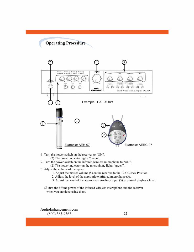
Example: CAE-100W
Example: AEH-07 Example: AERC-07
1. Turn the power switch on the receiver to “ON”. (2) The power indicator lights “green”. 2. Turn the power switch on the infrared wireless microphone to “ON”. (2) The power indicator on the microphone lights “green”. 3. Adjust the volume of the system 1. Adjust the master volume (5) on the receiver to the 12-O-Clock Position 2. Adjust the level of the appropriate infrared microphone (3). 3. Adjust the level of the appropriate auxiliary input (5) to desired playback level ◎Turn the off the power of the infrared wireless microphone and the receiver when you are done using them.
2
1 3
6 5
1 2
2
1
Operating Procedure

AudioEnhancement.com (800) 383-9362 23
1. Turn “off” the power switch (1). Check that the power indicator (2) has gone out. 2. Check that the power indicator (2) has gone out. For the 【AEH-07】, turn the battery case to the left to remove it. For the 【AERC-07】, pull the cover of the battery case, on the back of the mi-crophone, in the direction of the arrow to remove it. 3. Insert the battery. Use two NiMH batteries and be sure to check their polarity. 4. Put it back together. Replace the battery case (5). ●The microphones use two Panasonic nickel- hydrogen batteries HHR-210AAB2B
Changing the Battery
1 2
4
4
2
1

AudioEnhancement.com (800) 383-9362 24
Charging example (2) Charging example (1)
AC adapter AEBC-07 (NSA18EU-
050200) for the Charger Stand
AC adapter AEBC-07 (NSA18EU-050200) for the battery
charger
Charging Stand CS-07
There are two ways to charge the batteries shown below. Use the battery charger or plug the AC adapter directly into the microphone. ●Charge the batteries with the battery charger. (Charging example (1) above) ◎Charge the batteries by inserting the infrared wireless microphone into the bat-tery charger provided specifically for the infrared wireless microphone. ・ To charge the hand-held microphone "AEH-07" attach the adapter (3) and then insert the microphone. ・ Insert the Teardrop Microphone "AERC-07" directly into the charger to charge it. ●Insert directly into the AC adapter. (Charging example (2) above) ◎Charge the infrared wireless microphone by inserting the DC plug of the AC adapter provided for charging the batteries. ●Uses two Panasonic NIMH AA rechargeable batteries. ●Use the specialized battery charger or the AC adapter for charging the NIMH batteries. Charging time is approximately four hours but may vary depending on the con-ditions of the battery.
Charging the Battery
AC 120V
AC 120V

AudioEnhancement.com (800) 383-9362 25
The volume level of the infrared wireless microphones and the auxiliary inputs can be controlled form the teardrop infrared wireless transmitter. To control the level infrared wireless microphones and the signal level from the auxiliary in-puts. First adjust the volume to an appropriate level with the controls that are part of the receiver/amplifier system. Once the initial volume levels are set, the teacher can then adjust the level of either her own microphone, the other infrared wire-less microphone in the classroom, or the auxiliary input volume level. (The "AERC-07" is the only microphone that has infrared remote control of the re-ceiver\amplifier.) ●Adjusting the level of the audio signal output from the receiver. 1. Select which infrared microphone to adjust the volume of with the vol-ume controller selector switch. Select whether to adjust the volume of your "OWN“ microphone or the "OTHER“ microphone by selecting “OWN” or “OTHER” on the ”volume con-troller selector switch" on the "AERC-07". 2. Press the control switch. To increase the volume level press the "△“ button of the "Microphone volume control switch", to decrease the volume level press the "▽" button. ●Adjusting the level of the auxiliary inputs. 1. Press the control switch (13). To increase the volume level press the "△“ button of the "Microphone volume control switch", to decrease the volume level press the "▽" button. 【notes】 ◎The Level is adjusted in 2dB steps from +6dB to –16dB ◎These electronic adjustments are automatically reset to ‘0’ when the receiver/amplifier is turned off. ◎The control switch for aux inputs does not work for 20W amplifier (CAE-20W) and 2 channel receiver (RC-07)
(11) Volume control select switch [MIC SE-LECT]
Own –△ ▽ controls that micro-phones volume level
Other –△ ▽ controls the other infrared microphones vol-ume level
(12) Microphone volume control (13) Line volume control
11
12 13
Controlling the Volume
AudioEnhancement.com (800) 383-9362 26
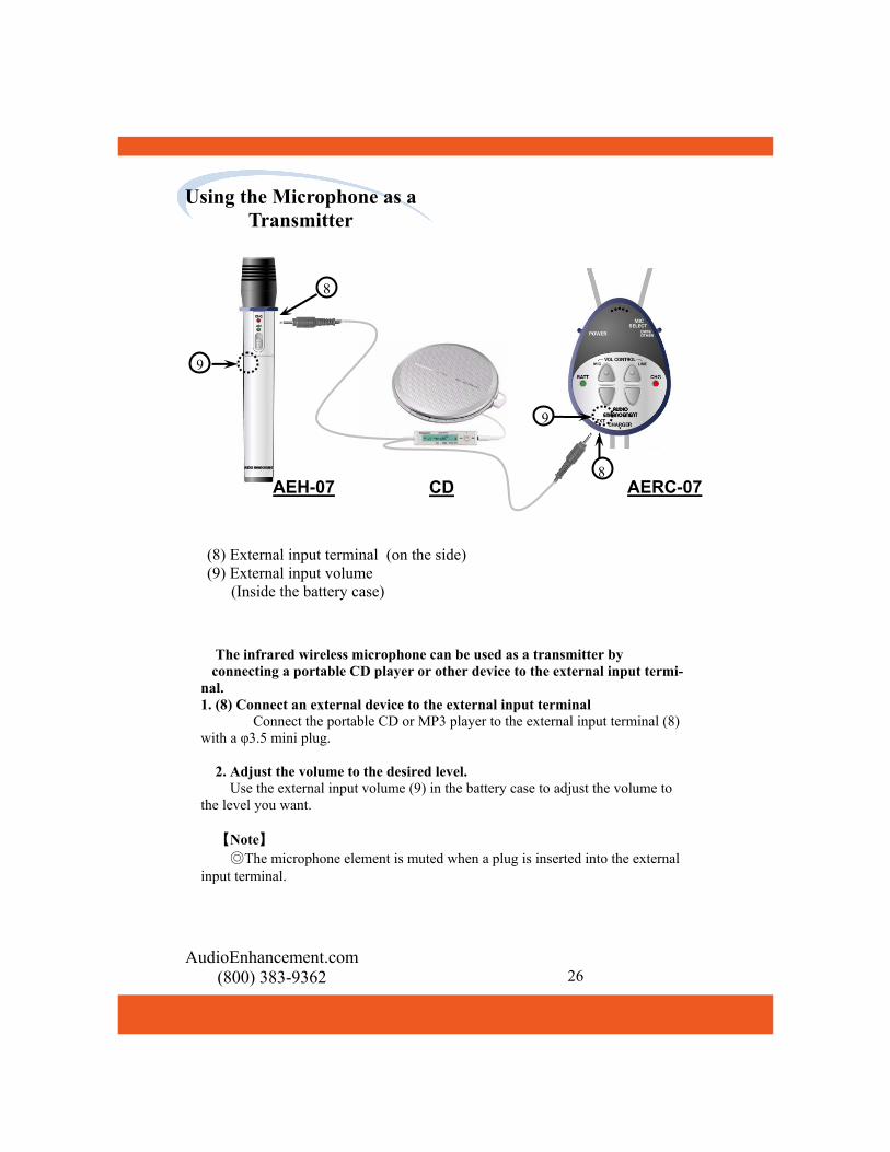
(8) External input terminal (on the side) (9) External input volume (Inside the battery case)
The infrared wireless microphone can be used as a transmitter by connecting a portable CD player or other device to the external input termi-nal. 1. (8) Connect an external device to the external input terminal Connect the portable CD or MP3 player to the external input terminal (8) with a φ3.5 mini plug. 2. Adjust the volume to the desired level. Use the external input volume (9) in the battery case to adjust the volume to the level you want. 【Note】 ◎The microphone element is muted when a plug is inserted into the external input terminal.
AEH-07 AERC-07
CD
9
8
9
8
Using the Microphone as a Transmitter

AudioEnhancement.com (800) 383-9362 27
◎This connection diagram is an example of using 3 to 4 infrared wireless mi-crophones with the "CAE-100W" infrared receiver/amplifier. When using only two microphones, one of the “EDS-07”sensors and the “AE-DCF” mixer are not necessary. In that case, set the "frequency selector switch" on the sensor according to the microphone channels being used. ◎ If you are connecting the "CAE-50W“ receiver amplifier, one or two infra-red wireless microphones can be used. With this configuration one of the "EDS-07" sensors and the "AE-DCF" mixer are not necessary. With this con-figuration, set the "frequency selector switch" on the sensor to A: 1ch/2ch.
CAE-100W
EDS-07
DVD recorder
Specified AC adapter
PW-150A2-1Y-240E
Coaxial cable
Pin plug (stereo type) F-connector
Coaxial cable
Coaxial cable
AE-DCF
A: 1ch/2ch
B: 3ch/4ch
Bundle the cables with tie wraps and fasten them to the "mount for the cable clamp".
Installation
AC 120V

AudioEnhancement.com (800) 383-9362 28
Installation
CAE-20W
DVD recorder etc.
Specified AC adapter
3A-621DA24
・・・ Pin plug ・・・ F-connector
Coaxial cable
A: 1ch/2ch setting
Bundle the cables with tie wraps and fasten them to the "mount for the cable clamp".
AC 120V
■Connections ◎Remove the AC power cord from the power outlet when connecting the system. ◎Use the specified AC adapter. ●Basic Connections for the "CAE-20W" ◎This connection diagram is an example of using 1 or 2 infrared wireless microphones with the "CAE-20W" infrared wireless receiver/amplifier. With this configuration set the "frequency selector switch" on the sensor to A: 1ch/2ch.

AudioEnhancement.com (800) 383-9362 29
Installation
RC-07
EDS-07
DVD recorder etc. Specified AC adapter 3A-621DA24
・・・ Pin plug ・・・ F-connector
Coaxial cable
A: 1ch/2ch setting Bundle the cables with tie wraps and fasten them to the "mount for the cable clamp.”
・・・ TS phone
Amplifier
Switch the level to "MIC/LINE" according to the type of input on the amplifier.
AC 120V
■Connections ◎Remove the AC power cord from the power outlet when connecting the sys-tem. ◎Use the specified AC adapter. ●Basic Connections for the "RC-07" ◎This connection diagram is an example of using 1 or 2 infrared wireless mi-crophone with the "RC-07" infrared receiver. With this configuration set the "frequency selector switch" on the sensor to A: 1ch/2ch.

AudioEnhancement.com (800) 383-9362 30
CAE-100W
EDS-07 Coaxial cable
F-connector
Coaxial cable
Coaxial cable
AE-DCF
A: 1ch/2ch A: 1ch/2ch
EDS-07
B: 3ch/4ch B: 3ch/4ch
EDS-07 EDS-07 Coaxial cable Coaxial cable
●For Reception in Large Areas ◎This connection diagram is an example using from 3 to 4 infrared wire-less microphones with the "CAE-100W“ receiver/amplifier. For reception in large areas, add two "EDS-07" sensors as shown below. ◎Up to 4 "EDS-07" sensors can be added to the CAE-50W receiver ampli-fier. With this configuration, set all the "frequency selector switches" to A: 1ch/2ch.
Installation
Specified AC adapter
PW-150A2-1Y-240E
AC 120V

AudioEnhancement.com (800) 383-9362 31
●Precautions for Installing the Sensors ◎Install the infrared sensors in a position that allows them to receive the infrared signal regardless of the teachers movement around the classroom. ◎Do not install the sensors in direct sunlight or directly in front of strong lighting fix-tures. In particular, in case of the sensor is installed near by a window. Even if the sensor is not in direct sunlight, affections from sunlight may reduce the effective range of the sensor. Install the infrared sensor as far away as possible (more than 5 meters) from a window. In spite of installed far away more than 5 meters from the windows, the effec-tive range of the sensor don’t be improved, try to install more and more far away from a windows, or try to use curtains or blinds for protection from the sun. ◎When using a plasma display in a space that has the infrared sensor, please choose the following guidelines. • Please choose the plasma display which be equipped infrared resonance sheet to
itself. • If using both the infrared sensor and the plasma display equipped no infrared reso-
nance sheet in a same space, it has possibilities of making a noise. • If there is no choice but to use the plasma display equipped no infrared resonance
sheet, please use with attention of the following guidelines. (Continue page 32)
Installation
Mor
e th
an tw
o m
eter
s
Floor
Ceiling
Sensor
Coaxial cable Fix coaxial cable

●Precautions for Installing the Sensors
・Install the infrared sensor in a position from which the screen of the plasma display cannot be seen, in other words, in the zone which is crosswise direction or behind from plasma display, and install the infrared sensor as far away as pos-sible (more than 10 meters) from the plasma display. ・Keep the infrared microphone and the photoreceptor sensor as close as possible (less than 3 meters). ・Please use the infrared microphone keeping no screen (include human body ) between the infrared microphone and the photoreceptor sensor. ◎Install the infrared sensor as far away as possible (more than 1 me-ter) from fluorescent lighting. ◎The sensors may not operate if there is a strong source of electro-magnetic noise (I.e. fluorescent lighting ballasts) causing interference. Install the sensor far enough away from the noise source. ◎The sensors are designed for ceiling-heights from two to four meters. (6 to 12 feet) If the ceiling height exceeds this height the effective range of the sensor may be reduced. Caution: Attach the coaxial cable used to connect the infrared sensor to the receiver to structure above the ceiling. This will prevent the sensor from falling should the screws come out. (Refer to diagram below)
AudioEnhancement.com (800) 383-9362 32
Installation

AudioEnhancement.com (800) 383-9362 33
Anchor strap Coaxial cable
Adjuster
Ceiling panel
Installation bracket
Installation screw
●Installing the Sensors: Part 1 Install the sensors as shown below if the coaxial cables have been routed through the ceiling and the ceiling panels can be removed. 1. Cut a hole in the ceiling panel. Remove the ceiling panel and cut a hole about φ30 mm in it and pull the cable through it. 2. Attach the anchor strap. Put coaxial cable through the anchor strap and tighten the adjuster. 3. Install the sensor. Push the coaxial cable and the safety strap back into the hole. Put the screw through the sensor and screw it into the installation bracket. Tighten the screw 4. After installation, make sure nothing is loose. Do a visual check and make sure that nothing is unsteady and the screws are
tight.
Installation

AudioEnhancement.com (800) 383-9362 34
Installation bracket: dia-gram for bending
Bend it according to the grooves.
Anchor strap
Coaxial cable
Adjuster
Ceiling panel Installation-bracket
Installation screw
Screws
●Installing the Sensors: Part 2 If the coaxial cables cannot be routed through the ceiling. You can install the sensors as shown below if the ceiling panels cannot be removed. 1. Bend the installation bracket. Bend the installation bracket as shown in the diagram below. 2. Attach the installation bracket to the ceiling. Attach the installation bracket to the ceiling with the screws. 3. Attach the anchor strap. Put coaxial cable through the anchor strap and tighten the adjuster. 4. Install the sensor. Put the screw through the sensor and screw it into the in-stallation bracket. Tighten the screws 5. After installation, make sure nothing is loose. Do a visual check and make sure that nothing is unsteady and the screws are tight. Caution: The screws for attaching the installation bracket to the ceiling panel are not provided. Procure these screws separately according to the material, construction and weight of the ceiling panel.
Installation

AudioEnhancement.com (800) 383-9362 35
Receiving from1ch/2ch(3ch/4ch)
●Range and Expansion of the Sensor Reception ◎One dome type infrared sensor has a practical range of approximately 24’. ◎Use the "AE-DCF" mixer to increase the number of sensors to cover a larger room. A total of four sensors can be added by using the "AE-DCF"
Installation
Approximately 24’
Room
For one photoreceptor sensor
For four photoreceptor sensors
For two photoreceptor sensors
Receiving from 1ch to 4ch
For one set of photoreceptor sensors For two sets of photoreceptor sensors
: 1ch/2ch : 3ch/4ch setting
Room Room
Room Room
Approximately 24’ Approximately 24’
Approximately 24’
Approximately 24’ Approximately 24’
Approximately 24’ Approximately 24’
Approximately 24’ Approximately 24’

AudioEnhancement.com (800) 383-9362 36
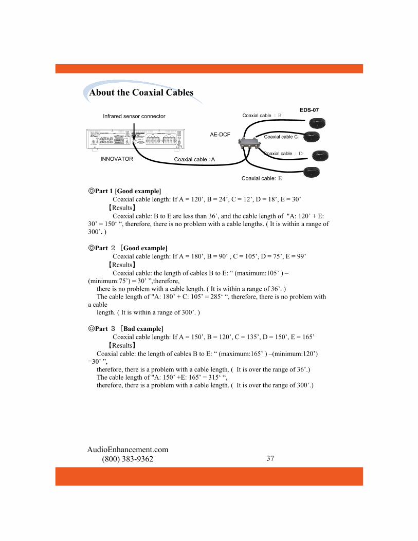
INNOVATOR Coaxial cable
AE-DCF
EDS-07
Coaxial cable :A
Coaxial cable :B
Coaxial cable :E
Infrared sensor connector
Coaxial cable :
●The following types and lengths of coaxial cables are recommended Use the following lengths and types of coaxial cables to connect the main unit and the sensors. ◎Coaxial cable length ・・・・・・・・・ Less than 300’ ◎Coaxial cable type ・・・・・ RG6 ●When using the "AE-DCF" sensor coupler Keep the total length of coaxial cable from the main unit to the coupler "coaxial cable length: A" and from the coupler to each sensor "coaxial cable length: B to E" within a range of 300 feet. 【Caution】 Keep the differences of the length among cables from AE-DCF to EDS-07 (among cables B to E) less than 36’.
About the Coaxial Cables
AudioEnhancement.com (800) 383-9362 37
INNOVATOR Coaxial cable :D
AE-DCF
EDS-07
Coaxial cable :A
Coaxial cable :B
Coaxial cable: E
Infrared sensor connector
Coaxial cable C
◎Part 1 [Good example] Coaxial cable length: If A = 120’, B = 24’, C = 12’, D = 18’, E = 30’ 【Results】 Coaxial cable: B to E are less than 36’, and the cable length of "A: 120’ + E: 30’ = 150‘ “, therefore, there is no problem with a cable lengths. ( It is within a range of 300’. ) ◎Part 2 [Good example] Coaxial cable length: If A = 180’, B = 90’ , C = 105’, D = 75’, E = 99’ 【Results】 Coaxial cable: the length of cables B to E: “ (maximum:105’ ) –(minimum:75’) = 30’ ”,therefore, there is no problem with a cable length. ( It is within a range of 36’. ) The cable length of "A: 180’ + C: 105’ = 285‘ “, therefore, there is no problem with a cable length. ( It is within a range of 300’. ) ◎Part 3 [Bad example] Coaxial cable length: If A = 150’, B = 120’, C = 135’, D = 150’, E = 165’ 【Results】 Coaxial cable: the length of cables B to E: “ (maximum:165’ ) –(minimum:120’) =30’ ”, therefore, there is a problem with a cable length. ( It is over the range of 36’.) The cable length of "A: 150’ +E: 165’ = 315‘ “, therefore, there is a problem with a cable length. ( It is over the range of 300’.)
About the Coaxial Cables

AudioEnhancement.com (800) 383-9362 38
AEH-07
AERC-07
(5) Battery case (10) frequency selector switch (Inside the battery case)
(1) Frequency selector switch
The settings for the frequency of the infrared wireless microphone and the infrared sensor may be different depending on the equipment you are using. ●If the main unit you are using is the "CAE-50W", the "CAE-20W", or the "RC-07“ then the frequency settings for the sensor and the infrared wireless microphone are as follows: 1ch: 2.30 MHz, 2ch: 2.80 MHz ●If the main unit you are using is the "CAE-100W" then the frequency settings for the sensor and the infrared wireless microphone are as follows. 1ch: 2.30 MHz, 2ch: 2.80 MHz, 3ch: 3.20 MHz, 4ch: 3.80 MHz ●Remove the case of the infrared wireless microphone and set the transmission frequency Use the frequency setting switch to select the desired transmission channel. Position [0] = Channel 1: 2.30 MHz, position [1] = Channel 2: 2.80 MHz Position [2] = Channel 3: 3.20 MHz, position [3] = Channel 4: 3.80 MHz ●Setting the sensor's reception frequency. The reception frequency changes when the position of the frequency setting switch is changed. [A] position = Channel 1: (2.30 MHz)/Channel 2: (2.80 MHz) [B] position = Channel 3: (3.20 MHz)/Channel 4: (3.80 MHz)
10
5
10
5
1
Setting the Frequency

AudioEnhancement.com (800) 383-9362 39
(11) Input terminal (13) AUX mute setting switch
●Setting the Mute for the Audio Input of the Infrared Wireless Microphone Reduces the volume of the auxiliary inputs when the teacher speaks into the infrared wireless microphone.
●Set the "(13) AUX MUTE" switch to activate this function. ◎ "OFF" position ・The auxiliary inputs are not muted when the teacher speaks into the infrared wire-less microphone. ◎"LOW" and "HIGH" positions ・Reduces the volume of the auxiliary inputs while the teacher is speaking into the infrared wireless microphone. The Low setting provides for a standard level of attenuation. The High setting provides for a faster attenuation. Set the switch to ‘low’ for normal opera-tion.
13 11
Setting the Aux Mute
[Notes] ◎If extraneous sounds are causing the auxiliary inputs to mute at unwanted times set the "(13) AUX MUTE" switch in the "LOW“ position. This setting will require that a sound source be closer to the microphone to activate the muting function. The Mute functions work as depicted below:
Muting of auxiliary input starts
Muting function ends when teacher stops speaking into the
microphone
Time
Volume
Auxiliary Input level
Auxiliary input levels reduced by
12 dB
Auxiliary Input volume returns to original level after approximately 2 seconds

AudioEnhancement.com (800) 383-9362 40
(11) Auxiliary Inputs (15) PA input terminal (16) PA input volume
PA cold signal PA hot signal
●Setting the Mute for the PA Input The Auxiliary Muting function Reduces the volume of the audio signals that are coming into the auxiliary input terminals every time an announcement over the PA system is made. This is accomplished by wiring the high impedance signal (70 or 25 Volt) from the PA system to the PA input terminals. Adjust the audio level of the PA system that is connected to the ‘hot’ and ‘common’ terminals of the PA input terminal (15) with the PA input volume (16), as shown in the diagram. 【notes】 ◎The AUX mute for the PA input terminal operates independently from the teacher voice mute settings. ◎Every time the PA system is activated, the announcement is reproduced by all of the speakers attached to the main unit. (Continue to next page)
11 15 16 15
16
Setting the PA Aux Mute

AudioEnhancement.com (800) 383-9362 41
Setting the PA Aux Mute
Caution : Wiring for the PA Input are fix the screw terminals.
Be sure to switch the amplifier off before connecting the wires. Carefully check the polarities before connecting it. Connection to the wrong polarity will cause trouble.
Screw terminals
Muting of auxiliary input
Mute finished when inputs turned off
Time
Volume Auxiliary Input
Level
Auxiliary input levels reduced by
12 dB
Auxiliary Input volume returns to original level
after approximately 10 seconds
(Continue from previous page) The mute function works shown as below:

AudioEnhancement.com (800) 383-9362 42
To activate the mute function, use a terminal jumper to connect the "+24 V BIAS“ terminal (17) and the "EMG CNT“ terminal. With the jumper in place, the auxiliary inputs will be muted when a page is received. To de-activate the muting function, connect the EMG termi-nal to the "EMG GND" terminal as shown in the diagram at right.
●Setting the Emergency Mute Function The Emergency Mute Function (EMG) (17) allows selection of whether or not the audio level of the auxiliary inputs (11) is muted when a page is received from the PA system.
【notes】 ◎The AUX mute for the PA input terminal operates independently from the teacher voice mute settings. (Continue to next page)
(11) Input terminal (17) EMG input terminal
17 11
Jumper 17
Setting the EMG Aux Mute

AudioEnhancement.com (800) 383-9362 43
Setting the EMG Aux Mute
Caution : Wiring for the ENG Input are fix the screw terminals. The torque for the screws is 0.98 N・m±0.1 N・m (10 kgf・cm±1 kgf・cm)
Muting of auxiliary input starts
Muting finished when inputs turned off
Time
Volume
Auxiliary Input Level
Auxiliary input levels reduced by
12 dB
Auxiliary Input volume re-turns to original level after approximately 2 seconds
(Continue from previous page) The mute function works shown as below:
Be sure to switch the amplifier off before connecting the wires. Carefully check the polarities before connecting it. Connection to the wrong polarity will cause trouble.
Screw terminals

AudioEnhancement.com 44
Personal computer Cable CAE-100W
(18) Serial transmission
The Audio levels of the "CAE-100W“ can be remotely controlled by connecting it to a per-sonal computer via a serial port. The microphone levels can be controlled independently, the auxiliary inputs are controlled as a single mixed signal. ●About connections Connect the "CAE-100W" and the personal computer with a cable as shown below.
●Serial transmission connection (RS232C) specifications The "INNOVATOR" specifications are shown below.
Signal Level Contents Description Sync.method Asynchronous Synchronizes every 1 character (8 bits) Baud rate 9600bps Data transfer speed Parity None Error detection method
Character length 8bits Number of bit composing 1 character
Stop bit 1bit Uses stop bit when asynchronous method Cable Type : Cross Maximum Cable Length less than 15m (40 feet)
PIN NAME PIN NAME1 N.C. (DCD) 6 N.C. (DSR)2 RXD 7 N.C. (RTS)3 TXD 8 N.C. (CTS)4 N.C. (DTR) 9 N.C. (RI)5 GND ---
●Information about Connectors
About External Control
RXD
GND
TXD
1
9
2
4
5
3
6
7
8
[notes] ◎Contact your local representative for additional information on controlling the CAE-100W from computer via the RS-232C input

AudioEnhancement.com (800) 383-9362 45
● Precautions for Installing the Infrared Receiver and Infrared Receiver/Amplifier ◎Infrared Receiver and Infrared Receiver / Amplifier will produce small amounts of heat. Provide a minimum of 10 cm when installing the amplifier close to the ceiling or wall. ◎ Infrared Receiver and Infrared Receiver / Amplifier are for indoor use only. They cannot be installed and used in any of the situations below.
・In a place where they can get wet. ・Where chemicals are used including under the eaves (ex. pool) ・Places that contain high amounts of steam, oil, or a flammable atmosphere. ・Places where radiation, such as X-ray or high radio waves magnetism are present. ・On the ocean, beach or place where corrosive gas, such as hot spring is present. ・In a place where high levels of vibration are present such as on a vehicle, or marine ves-sel. ◎When using the provided bracket, note the following points. ・Select a sturdy wall to install. ・Insure that the appropriate fasteners or screws are used, and that they are rated appro-priately for the load they will be required to carry. ・Insure that all the all directions from the manufacturer of the anchor, fastener or screw are followed. ・Do a visual check and make sure that nothing is unsteady and the screws are tight. ◎Note the following points when tightening bolts and screws. ・Proper torque must be applied to all bolts and screws. ・A torque wrench or a torque driver are required to set the proper torque. ・It is difficult to get the proper torque with an impact driver or electric driver even if it has a clutch, therefore they should not be used as they may damage the parts for the installation. ◎Note the following points when installing INNOVATOR or CAE-50W Infrared Receiver/Amplifier into a rack ・When mounting to a rack, remove the rubber feet from the base of the unit ・When installing near other heat-sensitive equipment, install the other equipment lower than the receiver/amplifier system. ・Install rack in a such a manner as to provide for sufficient airflow to maintain a tempera-ture of no more than 40℃ in the rack.
More Than 10
cm
More Than 10 cm
More Than 10 cm
Front side
Precautions for Installation

AudioEnhancement.com (800) 383-9362 46
Installing the Bracket
Installing MTBR-07L(STC-98014) for the CAE-50W and CAE-100W Receiver
Amplifier
Please carefully read the following assembly, installation and safety instructions
before installation of MTBR-07L Bracket for CAE-50W and CAE-100W
Receiver Amplifier.
1. Installation Surface – The enclosed accessories are suitable only for
attaching to walls made of solid concrete or wood studs. Do not install
to sheet rock or wood panel.
2. Tighten all the nuts using the wrench supplied with the mount. The nub
must be tightened until the threading of the screw passes the plastic part
of the nut.
3. Make sure that MTBR-07L Bracket is installed so the tray is above
average head height and doesn’t disturb free movement in hallways.
4. You must test the MTBR-07L Bracket before setting CAE-50W or
CAE-100W Receiver Amplifier.
5. Calculate the maximum weight allowed on the mount by
multiplying the specified weight (this weight will be specified in the
packaging of the bracket) by 1.75. (I.e. weight x 1.75).
6. Check that CAE-50W or CAE-100W Receiver Amplifier is securely
fastened to the bracket so it will not fall forward.
7. One month after installation and every six months after that, check that
MTBR-07L Bracket is securely fastened to the wall and the screws
and nuts are not loosening. In case of weakening, remove CAE-50W
or CAE-100W Receiver Amplifier, and strengthen all the points that
have weakened.
8. Before reinstalling MTBR-07L Bracket, remove CAE-50W or
CAE-100W Receiver Amplifier first and then remount according to this
manual instructions.
AudioEnhancement.com (800) 383-9362 47
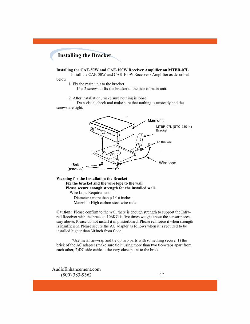
Installing the CAE-50W and CAE-100W Receiver Amplifier on MTBR-07L Install the CAE-50W and CAE-100W Receiver / Amplifier as described below. 1. Fix the main unit to the bracket. Use 2 screws to fix the bracket to the side of main unit. 2. After installation, make sure nothing is loose. Do a visual check and make sure that nothing is unsteady and the screws are tight.
Installing the Bracket
Warning for the Installation the Bracket Fix the bracket and the wire lope to the wall. Please secure enough strength for the installed wall. Wire Lope Requirement Diameter : more thanφ1/16 inches Material : High carbon steel wire rods Caution: Please confirm to the wall there is enough strength to support the Infra-red Receiver with the bracket. 106KG is five times weight about the sensor neces-sary above. Please do not install it in plasterboard. Please reinforce it when strength is insufficient. Please secure the AC adapter as follows when it is required to be installed higher than 30 inch from floor. *Use metal tie-wrap and tie up two parts with something secure, 1) the brick of the AC adapter (make sure tie it using more than two tie-wraps apart from each other, 2)DC side cable at the very close point to the brick.
To the wall
Wire lope
MTBR-07L (STC-98014) Bracket

AudioEnhancement.com (800) 383-9362 48
Installing the Bracket
Installing MTBR-07S(BT77) Bracket for Infrared Receiver RC-07 and
CAE-20W Receiver/Amplifier
Please carefully read the following assembly, installation and safety
instructions before installation of MTBR-07S Bracket for Infrared Receiver
RC-07 and CAE-20W Receiver/Amplifier.
1. Installation Surface – The enclosed accessories are suitable only
for attaching to walls made of solid concrete or wood studs. Do not
install to sheet rock or wood panel.
2. Tighten all the nuts using appropriate wrench.
3. Make sure that MTBR-07S Bracket is installed so the tray is
above average head height and doesn’t disturb free movement in
hallways.
4. You must test the MTBR-07S Bracket before setting Infrared
Receiver RC-07 or CAE-20W Receiver/Amplifier.
5. The maximum weight allowed on the mount is 55 lbs.
6. Check that the Infrared Receiver RC-07 or CAE-20W
Receiver/Amplifier is securely fastened to the bracket so it will not
fall forward.
7. One month after installation and every six months after that, check
that MTBR-07S Bracket is securely fastened to the wall and the
screws and nuts are not loosening. In case of weakening, remove
Infrared Receiver RC-07 or CAE-20W Receiver/Amplifier, and
strengthen all the points that have weakened.
8. Before reinstalling MTBR-07S Bracket, remove the Infrared
Receiver RC-07 or CAE-20W Receiver/Amplifier, first and then
remount according to this manual instructions.

● the Infrared Receiver RC-07,and CAE-20W Receiver/Amplifier on MTBR-07S Install the Infrared Receiver RC-07 and Low end Infrared Receiver / Amplifier CAW-20W as described below. 1. Fix the main unit to the bracket. Use 2 screws to fix the bracket to the side of main unit. The torque for the screws is 1.18 N・m±0.2 N・m (12 kgf・cm±2 kgf・cm) 2. Fix the adjustment bolts. The torque for the screws is 1.18 N・m±0.2 N・m (12 kgf・cm±2 kgf・cm) 3. After installation, make sure nothing is loose. Do a visual check and make sure that nothing is unsteady and the screws are tight. 4. Fix the wire lope to the wall.
Warning for the Installation the Bracket Fix the bracket and the wire lope to the wall. Please secure enough strength for the installed wall. Wire Lope Requirement Diameter : more thanφ1/16 inches Material : High carbon steel wire rods Caution: Please confirm to the wall there is enough strength to support the Infrared Receiver with the bracket. 106KG is five times weight about the sensor necessary above. Please do not install it in plasterboard. Please reinforce it when strength is insufficient. Please secure the AC adapter as follows when it is required to be installed higher than 30 inch from floor. *Use metal tie-wrap and tie up two parts with something secure, 1) the brick of the AC adapter (make sure tie it using more than two tie-wraps apart from each other, 2)DC side cable at the very close point to the brick.
AudioEnhancement.com (800) 383-9362 49
Installing the Bracket
To the wall
Wire lope
MTBR-07S (BT77) Bracket

AudioEnhancement.com (800) 383-9362 50
FUSE
CAE-100W CAE-50W CAE-20W RC-07F101 021806.3MXP 0218004.MXP 021802.5MXP 0218.315MXPF401 0218002.MXP 0218002.MXP 0218002.MXPF402 0218002.MXP 0218002.MXP 0218002.MXPF403 0218002.MXP 0218002.MXPF404 0218002.MXP 0218002.MXPF701 0218002.MXPF702 0218002.MXPF703 0218002.MXPF704 0218002.MXP
Manufacturer: Littelfuse, Inc. Series: 218 TABLE: Part Number of Fuse

AudioEnhancement.com (800) 383-9362 51
TURN on the transmitter (green LED will indicate power, red LED indicates that batteries need to be recharged). POWER on the amplifier (red LED will indicate power; green LED by teacher volume control indicates receipt of IR signal). TRANSMITTER/MICROPHONE needs to be worn in a way as to have a clear path to the receiving sensors. POSITION the transmitter/microphone six inches from your mouth. RELAX and speak at a comfortable level. Remember, you do not have to project your voice. CHARGE the batteries every day. Ni-MH batteries will last for 6-8 hours of continuous use. Recharge for at least 12 hours (overnight). (Ni-MH-Batteries need to be replaced annually.) HAVE ANOTHER PERSON MONITOR your amplified voice from time to time to make sure it is not too loud.
Teacher’s Check List

52
Transmitter is not working Is the battery light on your transmitter green? YES – Is the red light on your external sensor on? YES – Is there anything in the room blocking the sensor? YES – Move the obstruction and retry. If the problem is not fixed please contact Audio Enhancement. NO – Is there anything covering the transmitter?
YES – Free the transmitter from any obstructions. NO – Contact Audio Enhance-ment.
NO – Contact Audio Enhancement for assistance. NO – Have your batteries been charged overnight? YES – Are your batteries over 1 year old? YES – Try a new set of batteries. If the problem persists contact Audio Enhancement.
NO – When charging, verify the charger is fully plugged into outlet. If the problem per-sists contact Audio Enhancement.
NO – Charge the batteries overnight.
AudioEnhancement.com (800) 383-9362
Troubleshooting

AudioEnhancement.com (800) 383-9362 53
No Audio Is your power supply plugged into the amplifier/receiver and the wall out-let? YES – Is the power switch set to “On” and the indicator light red? YES – Is the teacher transmitter turned on with a green battery light? YES – Is the green indicator light on the amplifier/receiver for Teacher 1 or 2 on?
YES – Try another transmitter in your room to determine if it works and contact Audio En-hancement. NO – Verify if a red light is
showing on the dome sensor and contact Audio
Enhancement.
NO – Are your batteries fully charged? YES – If the batteries are more than 1 year old please replace the batteries. If the problem persists contact Audio En-hancement for assistance. NO – Charge the batteries overnight.
NO – Will other items power up in that outlet? YES – If available try another outlet. If the problem persists contact Audio Enhancement. NO – Contact the school NO – Plug in the amplifier/receiver to the wall outlet.
AudioEnhancement.com (800) 383-9362
Troubleshooting

AUDIO ENHANCEMENT Ship Equipment to: Attn: Repairs 14241 S. Redwood Rd PO Box 2000 Bluffdale, UT 84065 800-383-9362 RMA#____________
Repair Form Name:_______________________________________________ School/Company:______________________________________ Shipping Address:______________________________________ Attn:_________________________________________________ City/State/Zip:_________________________________________ Telephone: (____)______________________
Model #/Items Serial # & Channel # Reason for Return Billing Address:________________________________________ Attn:_________________________________________________ City/State/Zip:_________________________________________ Telephone: (____)______________________
Date Purchased:_______________ Invoice #_______________ *Please attach a copy of the invoice for proof of warranty. If out of
warranty, Purchase Order Number must be provided.
Is system under a purchased extended warranty/contract?
Yes No
Purchase Order #:____________________________________________ Credit Card # (Visa/MasterCard/Discover/American Express): __________________________________________________________ Expiration Date:__________________ Name on Card________________ Address for Card:_________________________________________ Authorized Signature:_________________________________________
Please call for RMA# before returning product(s)
Repair Form

AudioEnhancement.com (800) 383-9362 55
Notes

Damage due to misuse, ill treatment, unauthorized modifications and/or repair, are not covered by this warranty. Audio Enhancement is not
liable for consequential damages arising out of any failure of the equipment to perform as intended. Audio Enhancement shall bear no responsibility or obligation with respect to the manner of use of any
equipment sold by Audio Enhancement.
WARRANTY INFORMATION
The 100W, 50W, 20W, and RC-07 carries a two year warranty on parts and labor due to defects in material or workmanship Microphones, cords and chargers carry a 90 day warranty.
Batteries are not covered under warranty.
Audio Enhancement specifically disclaims and negates any war-ranty of fitness for a particular purpose of such equipment including, without limitation, any warranty that the use of such equipment for
any purpose will comply with applicable laws and regulations or over-come any specific hearing/auditory processing deficit. When return-
ing units for service, use adequate packaging to prevent shipping dam-age. If in doubt as to what is defective, return transmitter, receiver and microphone, along with a note indicating the trouble (cuts out, dead, distorted, etc.). Be sure to include your name, phone number, and return address. Most units are returned for service because of
dead batteries.
PLEASE DOUBLE CHECK BATTERIES BEFORE SENDING
UNITS FOR SERVICE. 14241 South Redwood Road
PO Box 2000 Bluffdale UT 84065
Toll Free: (800) 383-9362 Phone: (801) 254-9263 Fax: (801) 254-3802
A u d i o E n h a n c e m e n t . c o m