audio/video entry stations 1 or 4 pushs · pdf fileaudio/video entry stations 1 or 4 pushs...
TRANSCRIPT

AUDIO/VIDEO ENTRY STATIONS 1 OR 4 PUSHS BUTTONS
Range : IP INTERCOM
Series :
Installation � Connection � Programming � Use �
Datasheet n° 604-0013A www.castel.fr Page 1 / 10
PRESENTATION
Products reference: 560.0000 (CAP-IP-1B-P) - 560.1000 (CAP-IP-1B-W) - 560.2000 (CAP-IP-V1B-P) - 560.3000 (CAP-IP-V1B-W) - 560.0100 (CAP-IP-2B-P) - 560.1100 (CAP-IP-2B-W) - 560.2100 (CAP-IP-V2B-P) - 560.3100 (CAP-IP-V2B-W) - 560.0200 (CAP-IP-3B-P) - 560.1200 (CAP-IP-3B-W) - 560.2200 (CAP-IP-V3B-P) - 560.3200 (CAP-IP-V3B-W) - 560.0300 (CAP-IP-4B-P) - 560.1300 (CAP-IP-4B-W) - 560.2300 (CAP-IP-V4B-P) - 560.3300 (CAP-IP-V4B-W) The CAP IP entry station integrates complete and powerful Full IP capabilities. With native SIP, it offers the following principal functions (depending upon the version):
• Establish an audio/video communication over IP • Register on SIP Server (possibility to configure up to two backup servers) • Manage 1 to 4 push buttons • Manage 2 inputs « all or nothing » • A single-pole dry contact to control a keeper or other organ • Compliant with disabled accessibility: 3 LED associated with 3 symbols and 3 speech synthesizers allow a
signal call, communication or opening door • Manage the profiles according to the time • Manage its advanced automation interfaces (logical relations and schedules) • Provides H264 video stream for recording or monitoring • Perform autotests automatically or on demand • Update by TFTP (Trivial File Transfer Protocol) • Integrate SNMP protocol (Simple Network Management Protocol) • Integrate VLANs • Secure the Ethernet network by using the 802.1X protocol (Radius) • Backup on power failure. • POE function (Power Over Ethernet) • Wi-Fi function (option) • Thanks to its embedded web server, it can be configured, monitored and operated from any browser
CAP V2B IP CAP V3B IPCAP IP V1BCAP IP 1B CAP V4B IP
VERSIONS
• Version 6 PB or 10 PB: Audio only • Version 6 PB or 10 PB: Audio and video • All versions can have a Wi-Fi option

AUDIO/VIDEO ENTRY STATIONS 1 OR 4 PUSHS BUTTONS
Datasheet n° 604-0013A www.castel.fr Page 2 / 10
CONNECTION
15-3
0VD
C P
ower
sup
ply
RJ4
5: E
TH
ER
NE
T &
10
/10
0 P
OE
US
B (N
C)
Logi
c in
put 1
Logic input 2
Rel
ay o
utpu
t
Reset Button
Amplifier connectionor magnétic induction loop
R T E C
NO
NF
C
Connecting the power supply A 15-30V power supply is required. The station can be powered by the POE network.
Connecting the IP network The connection is made by Ethernet 10/100 Mbits RJ45.
Connecting the relay outputs The connection is made using a 3-point terminal that provides the "Contact (C) / Rest (R) / Office (W)" interface. If you use one of these relay outputs to control a 12, 24 or 48V AC or DC latch, connect an unpolarized 58V diode in parallel with the dry contact between C and W or C and R depending on the use (diode included).
Connecting the input 2 inputs TOR allows the connection of a dry contact (do not apply power) to be activated, the inputs must be pulled to ground. Contacts can be deported to 1km.
Protection against electrostatic discharge Connect the station to the ground using the supplied terminal (see label holder screw).

AUDIO/VIDEO ENTRY STATIONS 1 OR 4 PUSHS BUTTONS
Datasheet n° 604-0013A www.castel.fr Page 3 / 10
INSTALLATION
Surface mounting: Attach the back with three 3-3.5 mm screws maximum (see drawing below) Attach the front with 6 FHC M3-10 screws.
40
54,5
250
135
26
106
15,8
50
4013
055
210

AUDIO/VIDEO ENTRY STATIONS 1 OR 4 PUSHS BUTTONS
Datasheet n° 604-0013A www.castel.fr Page 4 / 10
Flush mounting Prepare hole of height 215 mm, width 110 mm and depth 45mm in wall. Coat the back of the hole with at least 10 mm fresh cement. Insert the back of the entry station and push it until the front touches the wall. Allow cement to dry at least 24 hours. Connect the entry station. Attach the front with 6 FHC M3-10 screws.
45
215
Fre
sh c
emen
t
Bulkhead mounting in plasterboard Prepare a hole of height 215 mm and width 115 mm in wall. Mount the claw kit in the entry station back. Attach the back of the entry station in the hole with claws. Connect the entry station. Attach the front with 6 FHC M3-10 screws.

AUDIO/VIDEO ENTRY STATIONS 1 OR 4 PUSHS BUTTONS
Datasheet n° 604-0013A www.castel.fr Page 5 / 10
Mounting on post Prepare the opening for mounting the entry station back on the post, as specified below. Attach the entry station back on the post with 4 FZ M3-10 screws (countersunk head). Connect the entry station. Attach the front with 6 FHC M3-10 screws.
15
0=
=
20
0=
=
21
5=
=
98= =
100= =
104= =
4 tapped holes M3
n106
AUDIO/VIDEO ENTRY STATIONS 1 OR 4 PUSHS BUTTONS
Datasheet n° 604-0013A www.castel.fr Page 6 / 10
USE
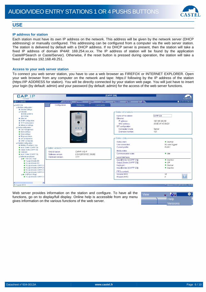
IP address for station Each station must have its own IP address on the network. This address will be given by the network server (DHCP addressing) or manually configured. This addressing can be configured from a computer via the web server station. The station is delivered by default with a DHCP address. If no DHCP server is present, then the station will take a fixed IP address of domain IP4All: 169.254.xx.xx. The IP address of station will be found by the application CastelIPSearch or CastelServer). Otherwise, if the reset button is pressed during operation, the station will take a fixed IP address 192.168.49.251.
Access to your web server station To connect you web server station, you have to use a web browser as FIREFOX or INTERNET EXPLORER. Open your web browser from any computer on the network and tape: https:// following by the IP address of the station (https://IP ADDRESS for station). You will be directly connected by your station web page. You will just have to insert your login (by default: admin) and your password (by default: admin) for the access of the web server functions.
Web server provides information on the station and configure. To have all the functions, go on to display/full display. Online help is accessible from any menu gives information on the various functions of the web server.

AUDIO/VIDEO ENTRY STATIONS 1 OR 4 PUSHS BUTTONS
Datasheet n° 604-0013A www.castel.fr Page 7 / 10
FUNCTIONS
The entry station is designed for dialogue via the IP network with other CAP IP stations, a software phone, an SIP phone or any other item which is compatible with SIP standards.
General entry station functions • Configure a network connection • Configure a SIP account • Set date and time manually or via a NTP server • Manage audio and video communication (depending on the version)
↘ Set a priority level on the station ↘ Set a time-out call and communication ↘ Automatic hanging up with and without delay ↘ Activate de privacy mode on the automatic hang-up
Audio interface functions • Set the loud-speaker and microphone volume • Set the type of phone (full duplex/ half duplex) • Set the level of ambient noise reduction • Configure the RTP port number • Validate/cancel audio codecs • Set the ringtone and tone • Configure DTMF commands for controlling (eg the local relay) • Configure the noise detection to trigger a call eg • Switch to simplex on dtmf commands (for entry stations with keyboard):
↘ '*' allow to switch in listen mode (mute the microphone on the station which receive the dtmf) ↘ '#' allow to switch in spoken mode (mute the microphone on the station which emit the dtmf) ↘ '0' allow to return to the standard mode (full or half duplex)
Video interface functions ↘ Configure the port RTP number ↘ Validate/cancel video codecs ↘ Set the bandwidth
Programmable function buttons Each button is programmable and allows:
↘ To make a call from 1 to 10 stations simultaneous or temporize ↘ Control the local relay, the station relay in communication ↘ Send a DTMF code ↘ End a call
Input interface functions For each input it is possible to:
↘ Configure the input as a “status” or “counter” ↘ Configure the active status of the input (open or closed contact) ↘ Configure timing to take into account status changes (anti-bounce-back function) ↘ Configure the counter threshold ↘ Block the input
Output interface functions The output interface relay is programmable; it is possible to:
↘ Configure the type of output relay; mono-stable, bi-stable or flashing ↘ Configure the type of contact: normally open/normally closed ↘ Control stop/go output ↘ Control force open/force closed output ↘ Configure the time parameters for output
Logical input web server function Logical input allows 2 kinds of functionality:
↘ Create a logic from which it will be possible to condition actions in relations ↘ Create a counter which will be updated as events and depending on the value of this counter start one or
more actions if required

AUDIO/VIDEO ENTRY STATIONS 1 OR 4 PUSHS BUTTONS
Datasheet n° 604-0013A www.castel.fr Page 8 / 10
Function related to the web server The web server is the point of parameters setting of the automatisms also called relations. There is 2 kind of relation:
• Time: Can start actions on identified time slots. There are 3 priority levels for a connection schedule (high, medium, small).
• Logical: ↘ Logical condition: Can start actions depending on the status. A logical relation can be integrated by some
operator as AND, OR, NOT, XOR. In the same way, a logical relation can start several actions. ↘ Numerical condition: Can perform actions by comparing the value of a counter with various thresholds. It
is also possible to add or subtract counter values and compare the results.
Function of the user web server Web server allows the station to grant, modify or delete privileges to users by specifying their login, password and operating language. On the user tab, you can create, import, export and visualize a directory. This directory is the set of users that can be calling from the station.
Function of the web server profile It’s possible to create modify or delete functional profile of the station. Each profile specify a priority of the station, a configuration of the buttons functions, a configuration of the directory (black list/white list) and security right of station. The station can function with a single profile or various profiles according to time slots.
Administration management SNMP The station includes an agent SNMP (Simple Network Management Protocol) to respond to SNMP requests and to send notifications (traps) to a SNMP manager. From web pages, you can:
• Configure different community (read / write) • Configure system data (“sysContact” and “sysLocation”) • Configure notifications (recipient, community ...) • Download “MIB Castel”
It supports SNMPv1 and SNMPv2c versions.
Autotest function The station has several tests to validate its functioning:
• Autotest “Micro and speaker”: to test the remote operation of speakers and microphone. From the page "Advanced Settings", it is possible to adjust levels of the test following the installation environment. This test can be triggered from the web server or an SNMP command. The test result is visible through the history of the web server and an SNMP notification.
• Autotest “keys”: the detection of a blocked mechanical button (contact for over 20s) is indicated by an SNMP notification and an event is reported in the history of the web server.
Safe and restore system setting You can save or restore the system setting of your station (configure, profile, relation, directory…). It’s possible to reset the station by pressing the reset button 10s at start of the station.
Update by TFTP Updating software with TFTP can be very useful when several stations must be updated. The station is looking forward a TFTP server which provides the available software release. If the station is concerned by this update, it downloads it and flashes it independently. The updating software takes place most of the time when the software release on the server is newer than the one installed on the station. It is possible to force an updating process to a specific release of the TFTP server. The TFTP server can request the stations to reset the current configuration, so the data partition is cleared. It is possible to configure the station to detect a new release when the station is starting or cyclically.
Backup on power failure When a power failure occurs, the station must be able to backup the following:
• Counter values • History • Secured events (these events are defined in VDIPServeur) • The states of interfaces
Web server historical function History allows you to view events on the station. They are listed showing the following information:
• Number • Date and time
AUDIO/VIDEO ENTRY STATIONS 1 OR 4 PUSHS BUTTONS
Datasheet n° 604-0013A www.castel.fr Page 9 / 10
• Interface concerned • Description of the event • Info 1 and info 2 (additional information)
Function to meet disabled accessibility (depending of the version) Law: “Any signal related to the operation of access system has to be audible and visual” When the call is made, the station emits a configurable voice message and signal call LED lights. When communication is established, the station emits a configurable voice message and signal communication LED lights. When the inside control relay station, the station emits a configurable voice message and the door opening signal LED lights. Law: “When there is an electric locking device, it must allow a disabled person to reach the door and start the opening operation until the door is locked again.” The latch relay of the station is configurable with a holding time adjustable. Law: Intercoms are equipped with a system allowing viewing their visitors. The station has a video camera. Law: “Intercoms with selectable list name can make a call by a code” Entry station with selectable list name and keypad allow direct call dialing.

AUDIO/VIDEO ENTRY STATIONS 1 OR 4 PUSHS BUTTONS
Environmental protection: Dispose of this product in compliance with environmental preservation regulations.
Datasheet n° 604-0013A www.castel.fr Page 10 / 10
CASTEL: Z.I. Saint Lambert des Levées - 49412 SAUMUR Cedex - France Tel.: +33 2.41.40.41.40 - Fax: +33 2.41.40.41.49
Non-binding photos and document. In constantly striving for improvement, the CASTEL company reserves the right to make any modifications it considers necessary.
TECHNICAL CHARACTERISTICS
Conformity to European Standards • Security rules according to:
↘ CEI/EN 60950-1. • Issuance of CEM according to:
↘ EN 61000-6-3 ↘ EN 55022 class B
• CEM immunity according to: ↘ EN 61000-6-1, EN 61000-4-2 (8 kV), EN
61000-4-3 (3V/m), EN 61000-4-4 (2kV). ↘ EN 55024
Mechanical characteristics • IP65 protection as per EN 60529 • Stainless steel front 316L • Aluminium box with wall mounting • Dimensions box: H 250mm x L 135mm x
Th. 54,5 mm • Weight : 1,4kg
General electrical characteristics • Protection against electrical shock, class 3,
according to EN 60950 • Functional temperature range: -20°C / +50°C • Storage temperature: -20°C / +70°C. • Relative Humidity: <90%, non-condensing • Power supply: 15VDC (15V to 30V) • Consumption: 15V/150mA at rest and
15V/200mA in communication
Button • Acquisition speed: 5Hz (200ms)
Inputs • 2 TOR inputs, protected and filtered • Acquisition speed: 5Hz (200ms)
Output • Relay output, potential-free • Ability to cut the relay 42.4 VAC/60
VDC/5A/150VA • Maximum frequency is 5 Hz (minimum
commutation time: 200ms)
Camera • CMOS 1/6’’ 640*480
Audio codec • G711 Ulaw/Alaw • GSM • G722
Video codec • Video format CIF/QCIF • H263 • H263-1998 • H264
DTMF • RFC-2833 • SIP INFO
Ethernet network 10/100 Mbit • IP fix or DHCP • Wi-Fi wireless network in conformity with IEEE
802.11b/g standard • POE class 2, conforms with IEEE 802.3af
standard • 802.1X protocol (Radius) • SNMP v1 & v2c