aurasense: robot collision avoidance by full surface
TRANSCRIPT

AuraSense: Robot Collision Avoidance by Full Surface Proximity Detection
Xiaoran Fan, Riley Simmons-Edler, Daewon Lee,Larry Jackel, Richard Howard and Daniel Lee
Abstract— Perceiving obstacles and avoiding collisions isfundamental to the safe operation of a robot system, partic-ularly when the robot must operate in highly dynamic humanenvironments. Proximity detection using on-robot sensors canbe used to avoid or mitigate impending collisions. However, ex-isting proximity sensing methods are orientation and placementdependent, resulting in blind spots even with large numbersof sensors. In this paper, we introduce the phenomenon ofthe Leaky Surface Wave (LSW), a novel sensing modality,and present AuraSense, a proximity detection system usingthe LSW. AuraSense is the first system to realize no-dead-spotproximity sensing for robot arms. It requires only a single pairof piezoelectric transducers, and can easily be applied to off-the-shelf robots with minimal modifications. We further introducea set of signal processing techniques and a lightweight neuralnetwork to address the unique challenges in using the LSW forproximity sensing. Finally, we demonstrate a prototype systemconsisting of a single piezoelectric element pair on a robotmanipulator, which validates our design. We conducted severalmicro benchmark experiments and performed more than 2000on-robot proximity detection trials with various potential robotarm materials, colliding objects, approach patterns, and robotmovement patterns. AuraSense achieves 100% and 95.3% truepositive proximity detection rates when the arm approachesstatic and mobile obstacles respectively, with a true negativerate over 99%, showing the real-world viability of this system.
I. INTRODUCTION
As robots and robot manipulators work in dynamic en-vironments, unexpected collisions with people and obstaclesmust be avoided. A robot colliding with the environment candamage itself or its surroundings, and can harm humans inthe workspace. Collision avoidance systems enable the robotto detect approaching obstacles in proximity to the robotbefore collision and take measures to avoid or mitigate im-pact. As such, there has been extensive research on collisionavoidance systems for robotic manipulators.
Unlike collision avoidance systems for automobiles, robotmanipulators usually operate in confined spaces, wherecollision avoidance depends on accurate short range sens-ing in cluttered 3D environments. Many existing collisionavoidance methods use cameras and computer vision-basedobject recognition or 3D shape reconstruction to detect andreact to obstacles. However, these approaches have severallimitations– their performance suffers when faced with ob-stacle occlusions, poor light conditions, and transparent ormirrored objects that are hard to detect visually. Further,camera-based approaches are typically not accurate over very
All authors are with Samsung AI Center NY, 837 Washington Street NewYork, New York 10014
Piezoelectric
Element
CollisionWarning!
No
Obstacle
Piezo Elements
Signal Processing
Neural Network
Robot Controller
DesignedWaveform
Processed Feature
Signal
Surface Wave
Obstacle
NearbyDeformed
Signal
DeformedSurface Wave
ProximityDetection
Fig. 1. AuraSense system configuration and overview.
short ranges (≤ 10cm), depending on camera focal length,and any single camera has a limited field of view.
To address this need for short range detection, proximitysensors such as ultrasonic proximity sensors [1], millimeterwave radar [2], infrared proximity sensors [3], and shortrange LiDAR [4] have been proposed specifically for robotcollision avoidance. These methods also have limitations:LiDAR and millimeter wave radar are expensive, and allthese methods are all highly directional– Effective coveragerequires multiple sensors distributed throughout the robot,and blind spots can be difficult to eliminate entirely withoutvast numbers of sensors. This complicates robotic systemdesign and adds significant sensor management overhead.
In this paper, we propose a novel sensing modality, whichwe term the Leaky Surface Wave (LSW), that enables no-dead-spot short range proximity detection for robots. Wedescribe a proximity detection system using this principle,AuraSense, which is lightweight, economical, can be attachedto an off-the-shelf robotic manipulator or mobile robotbody with minimal modifications, and provides proximitydetection of all objects with sufficient cross-sectional areaacross the entire surface of the robot. AuraSense is to ourknowledge the first system that can perform full surface andomnidirectional on-robot proximity detection for an entirelinkage using only a single sensor pair.
AuraSense uses one or more piezoelectric elements at-tached to a robot arm, and transmits excitation signals fromone element through the robot arm to other elements. Thisacoustic energy travels through the whole surface of the robotarm, which, through its vibration, couples the signal into theair. This acoustic signal decays rapidly with distance fromthe robot surface, forming an “aura” that is disturbed by thepresence of a foreign object in proximity. An approachingobstacle which enters this aura will establish a standing wave
pattern between the obstacle and the surface of the robot,changing the acoustic impedance of the system. This changecan be measured by the source transducer or another attachedelsewhere on the arm, potentially at a point far from theobstacle, allowing us to perform proximity detection.
To realize this concept, we address a number of technicaland implementation challenges. First, the major componentof the signal is received from the surface of the robot ratherthan the leaky over-the-air signal. However, only the leakyover-the-air signal contains information useful for proximitydetection. We employ a set of hardware enhancements andsignal processing techniques to extract this minor leakysignal from the large surface signal. Second, the robot armitself introduces both mechanical and electrical noise whichis received by the attached piezoelectric element. We solvethis issue by customizing the waveform, and further digitallyfiltering the noise. Last but not least, the received signal willvary non-linearly depending on the robot pose (includingself-detection) and relative obstacle position/velocity as therobot moves around. To resolve these issues, we use alightweight one-dimensional convolutional neural networkto identify whether a given received audio sequence corre-sponds to the presence of a non-self obstacle.
We present an end-to-end proximity detection system witha pair of low cost (< $2 ) piezoelectric elements attachedto an off-the-shelf commercial robot arm, and demonstrateno-dead-spot proximity sensing with several practical exper-iments. The simplicity of this design makes it easy to embedinto a robot with minimum modifications. To summarize, thispaper makes the following contributions:• We introduce a novel sensing modality, the Leaky
Surface Wave, which turns the entire robot surfaceinto a tactile skin that allows no-dead-spot proximitysensing on a robot arm. We build a real-world system,AuraSense, to demonstrate this new sensing capability.AuraSense is the first system to realize whole surfacecollision avoidance on a robot linkage.
• We explore the physics behind this new sensing modal-ity in the context of robotic systems. We propose severalsignal processing algorithms, a hardware configuration,and a lightweight 1D-CNN algorithm to specificallyaddress the unique challenges in our scenario.
• We implement an AuraSense prototype on a 7 degree-of-freedom (DOF) manipulator with a 96 kHz samplingrate audio chain, and conduct comprehensive evalua-tions of its real-world performance. Our multi-scenarioexperiments test performance on various approachingobjects with different dielectric and mechanical prop-erties, a range of approaching speeds and angles, andrandom robot movement patterns. AuraSense attains atrue positive rate of over 95% with a less than 1% falsepositive rate for on-robot proximity detection.
II. RELATED WORK
The LSW bares some similarity to surface acoustic waves(SAWs) [5], which also propagate waves along an object’ssurface between transmitter and receiver. However, SAWs
rely on the object itself being piezoelectric, operate at muchhigher frequencies (megahertz range), don’t leak waves intothe air, and are mostly used as signal filters.
On the application side, existing systems for on-robotcollision avoidance can be categorized into three types: 1)Computer vision-based collision detection, 2) Time-of-Flight(ToF) sensor based, and 3) Interference and capacitive sens-ing based. Computer vision-based solutions using monocularcameras [6], stereo cameras [7], and depth cameras [8]have been proposed, which seek to recognize obstacles inthe camera view. However, even with high performanceneural network models and algorithms, computer vision-based solutions are still limited by camera viewing angle,and lighting conditions, and may perform poorly on reflectiveand transparent obstacles. Camera based solutions are alsoin general not well-suited for short range (≤ 10cm) sensing,as such short focal lengths can require specialized lensesto avoid heavy distortion. Next, ToF methods can also beused to help robots avoid nearby obstacles. ToF signals canbe acquired from phased radar [9], lidar [4], or ultrasoundsensors [1]. However, tens or even hundreds of ToF sensorsmay be needed to provide whole surface proximity detectionwithout blind spots. This is impractical due to 1) the highcost of ToF sensors such as lidar or millimeter wave radar,and 2) large numbers of of ToF sensors emitting at the sametime will interfere with each other, which complicates systemdesign. Finally, other type of sensing modalities such asinfrared sensors [3] or capacitive coupling sensors [10] whichleverage signal interference patterns have been proposed foron-robot collision avoidance. However, these sensors areorientation-dependent, and capacitive sensing only works onobstacles that have purposely calibrated dielectric constants,such as water or human tissues.
AuraSense differs practically from these sensing modali-ties as it enables whole surface sensing capability with only asingle transmitter/receiver pair. To our knowledge, AuraSenseis the first system to provide no-dead-zone proximity sensingamong published on-robot proximity sensing systems.
III. METHODS AND SYSTEM DESIGN
In this section, we first introduce the core of our novelsensing modality. Next, we discuss how to leverage thisnew sensing modality for on-robot whole surface proximitydetection, from robot instrumentation to neural network clas-sification. We include proof-of-concept results throughout toillustrate important aspects of the system design.
A. Leaky Surface WaveAt the core of our sensing method is an acoustic signal,
the LSW. By coupling piezoelectric elements to the surfaceof an object with low acoustic loss, such as a robot arm madeof plastic or metal, and applying an excitation signal to thepiezoelectric element, acoustic waves propagate within andalong the surface of the object. As a result, the surface ofthe object will vibrate and couple acoustic energy to the air,making the entire surface an acoustic transducer. Notably,piezoelectric elements couple with the surface instead of theair, and could even be embedded within the object.
Surround leaky
surface wave
Interference
pattern
Piezo
receiver
Piezo
transmitter
Hand
approaching
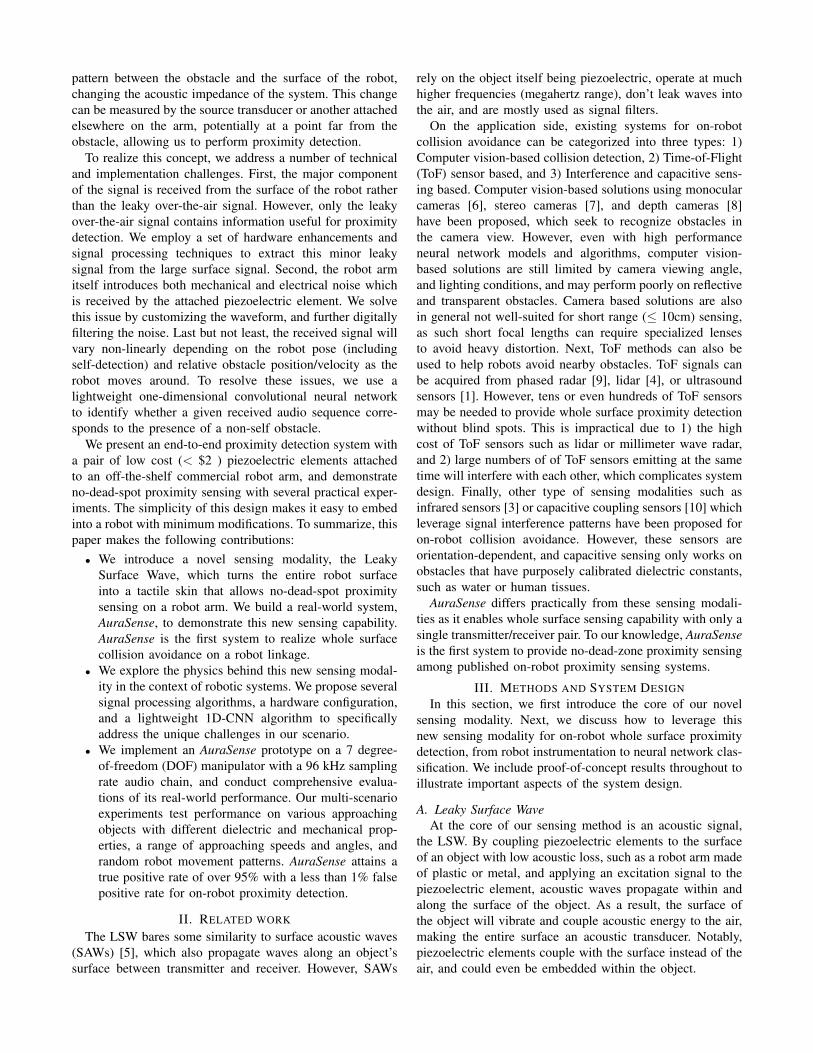
Fig. 2. A schematic of the LSWeffect. Approaching objects forman interference pattern with theLSW, which affects the surface-guided signal detected by the re-ceiver far from the interferencesite.
Hand
approaching
Piezo
receiver
Piezo
transmitter
AD-DA
Amp
Aluminum pipe
Fig. 3. We instrument an alu-minum pipe with two piezoelec-tric elements and apply a contin-uous sinusoidal excitation signalto one the piezo elements. Theother element records the LSWsignal.
TouchApproaching Retreat
(a)
Approaching process zoom in
Detected
Touch
(b)
Fig. 4. The recorded signal from the first proof-of-concept experi-ment, showing responses to proximity and contact. (a) The wholesignal, including approach, touch and retreat. (b) Enlarged windowof when the hand approached the pipe.
A schematic illustrating how the LSW can be distortedis shown in Figure 2. While most of the acoustic energyfrom the transmitter stays on the surface, a small amount“leaks” into the air. This leaky signal decays rapidly withdistance from the surface, resulting in an acoustic pressurefield “aura” that surrounds the object. Obstacles close tothe surface of the object will establish a standing wavepattern between the obstacle and the object surface , whichperturbs the acoustic pressure field and results in an acousticimpedance change across the entire surface. These changescan be detected by a piezoelectric element elsewhere onor within the object, acting as a receiver. As the signalpropagates through the object, obstacles close to any pointon the object’s surface will cause distortions that can bemeasured at other points on or within the object, allowingfor a single transmitter/receiver pair to detect obstacles closeto any part of the coupled object.
Properties of the LSW: This surface acoustic pressure fielddistortion displays a number of useful properties, whichwe will demonstrate in this section. We performed severalsimple experiments, using the setup shown in Figure 3. Weexcite the piezo transmitter with a 20 kHz signal. In the firstexperiment, a person’s hand approaches the pipe, touchesit, and then retreats. Figure 4(a) shows the signal recordedin this experiment; touching the pipe (at 2.2-3 seconds)introduces a major signal perturbation. In addition, if welook closely at the signal when the hand is approaching thepipe, shown in more detail in Figure 4(b), the approach of thehand (at 1.5-2.2 seconds) is detected as well. The peaks anddips reflect the standing wave pattern between the hand and
TouchApproaching
(a)
Location 2
Location 1
Location 3
(b)
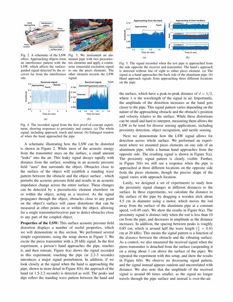
Fig. 5. The signal recorded when the test pipe is approached fromthe side opposite the receiver and transmitter. The hand’s approachis detected without line of sight to either piezo element. (a) Thesignal as a hand approaches the back side of the aluminum pipe. (b)Hand approach signals from approaching three different locationson the pipe.
the surface, which have a peak-to-peak distance of d = λ/2,where λ is the wavelength of the signal in air. Importantly,the amplitude of the distortion increases as the hand getscloser to the pipe. This signal pattern varies depending on thenature of the approaching obstacle and the obstacle’s positionand velocity relative to the surface. While these distortionscan be small and hard to interpret, measuring them allows theLSW to be used for diverse sensing applications, includingproximity detection, object recognition, and tactile sensing.
Next we demonstrate how the LSW signal allows fordetection across whole surface. We performed an experi-ment where we mounted piezo elements on one side of analuminum pipe, while a human hand approaches from theopposite side. The resulting signal is shown in Figure 5(a).The proximity signal pattern is clearly visible. Further,in Figure 5(b) we still see a response when the pipe isapproached at three different locations on the opposite sidefrom the piezo elements, though the precise shape of thesignal varies with approach location.
Lastly, we designed a set of experiments to study howthe proximity signal changes at different distances to thesurface. In these experiments, we calculate the distance tothe surface of the pipe by dragging a wooden stick about4.5 cm in diameter using a motor, which moves the rodaway from the surface of the aluminum pipe at a constantspeed, v=0.49 cm/s. We show the results in Figure 6(a). Theproximity signal is distinct only when the rod is less than 10cm from the pipe, and decreases in amplitude as the distanceincreases. In addition, the spacing between peaks is roughly0.85 cm, which is around half the wave length (λ2 = 0.85cm at 20 kHz). This means the signal pattern is a function ofthe distance between the obstacle and the vibrating surface.As a control, we also measured the received signal when thepiezo transmitter is detached from the surface (suspending iton a string about 1 cm above the surface of the pipe). Werepeated the experiment with this setup, and show the resultsin Figure 6(b). We observe no decreasing signal pattern,and the signal instead appears random and uncorrelated withdistance. We also note that the amplitude of the receivedsignal is around 60 times smaller, as the signal no longertravels through the pipe surface and instead is over-the-air.
Decreasing trend
(a) (b)
Fig. 6. Recordings showing how the LSW signal is affected by thedistance between the pipe and a wood block moving at constantvelocity away from the pipe. (a) As the rod moves further awayfrom the pipe, we see a decreasing amplitude pattern when thetransmitter is attached to the pipe. (b) We do not observe this patternwhen the transmitter is instead suspended 1 cm above the pipe.
(a) (b)
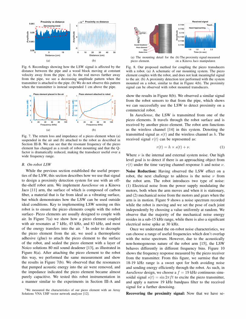
Fig. 7. The return loss and impedance of a piezo element when (a)suspended in the air and (b) attached to the robot as described inSection III-B. We can see that the resonant frequency of the piezoelement has changed as a result of robot mounting and that the Q-factor is dramatically reduced, making the transducer useful over awide frequency range.
B. On-robot LSW
While the previous section established the useful proper-ties of the LSW, this section describes how we use that signalto design a proximity detection system for use with an off-the-shelf robot arm. We implement AuraSense on a KinovaJaco [11] arm, the surface of which is composed of carbonfiber, a material that is far from ideal as a vibrating surface,but which demonstrates how the LSW can be used outsideideal conditions. Key to implementing LSW sensing on thisrobot is to ensure the piezo elements couple with the robotsurface- Piezo elements are usually designed to couple withair. In Figure 7(a) we show how a piezo element coupledwith air resonates at 7 kHz, 45 kHz, and 83 kHz, and mostof the energy transfers into the air. 1 In order to decouplethe piezo element from the air, we used a thermoplasticadhesive (glue) to attach the piezo element to the surfaceof the robot, and sealed the piezo element with a layer ofNoico solutions 80 mil sound deadener [13], as illustrated inFigure 8(a). After attaching the piezo element to the robotthis way, we performed the same measurement and showthe results in Figure 7(b). We observed that the resonancesthat pumped acoustic energy into the air were removed, andthe impedance indicated the piezo element became almostpurely capacitive. We tested this robot instrumentation ina manner similar to the experiments in Section III-A and
1We measured the characteristics of our piezo element with an ArraySolutions VNA UHF vector network analyzer [12].
Robot Arm
Glue
Piezo Element
Sound Deadener
(a) The mounting detail for thepiezo element.
Hand Approaching
Touch
(b) The proximity signal measuredon a Kinova Jaco manipulator.
Fig. 8. Our proposed method for coupling the piezo transducerswith a robot. (a) A schematic of our mounting system. The piezoelement couples with the robot, and does not leak meaningful signalto the air. (b) A proximity detection test performed with the systemmounted on a robot, similar to that in Figure 4(b). The proximitysignal can be observed with robot mounted transducers.
show the results in Figure 8(b). We observed a similar signalfrom the robot sensors to that from the pipe, which showswe can successfully use the LSW to detect proximity on acommercial robot.
In AuraSense, the LSW is transmitted from one of thepiezo elements. It travels through the robot surface and isreceived by another piezo element. The robot arm functionsas the wireless channel [14] in this system. Denoting thetransmitted signal as s(t) and the wireless channel as h. Thereceived signal r(t) can be represented as:
r(t) = h× s(t) + ν. (1)
Where ν is the internal and external system noise. Our highlevel goal is to detect if there is an approaching object fromr(t) under the time varying channel response h and noise ν.
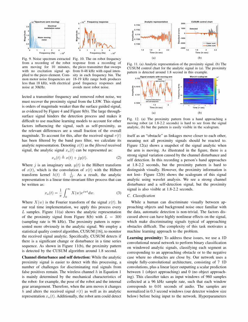
Noise Reduction: Having observed the LSW effect on arobot, the next challenge to address is the noise ν fromthe robot arm. The robot introduces two type of noise:(1) Electrical noise from the power supply modulating themotors, both when the arm moves and when it is stationary,and (2) mechanical noise from the motors and gears when thearm is in motion. Figure 9 shows a noise spectrum recordedwhile the robot is moving and we set the pose of each jointindependently by choosing a value uniformly at random. Weobserve that the majority of the mechanical noise energyresides in a sub-15 kHz range, while there is also a significantelectrical noise spike at 30 kHz.
Once we understand the on-robot noise characteristics, wecan choose a range of useful frequencies which don’t overlapwith the noise spectrum. However, due to the acousticallynon-homogeneous nature of the robot arm [15], the LSWbehaves differently in different frequency bins. Figure 10shows the frequency response measured by the piezo receiverfrom the transmitter. From this figure, we surmise that the18-19 kHz range is a sweet spot for both avoiding noiseand sending energy efficiently through the robot. As such, inAuraSense design, we choose a f = 19 kHz continuous sinu-soidal signal s(t) = sin 2πft to excite the piezo transmitter,and apply a narrow 19 kHz bandpass filter to the receivedsignal for a further denoising.
Recovering the proximity signal: Now that we have se-
Motor moving
noise
Electrical
modulation noise
Fig. 9. Noise spectrum extractedfrom a recording of the robotarm moving for 10 minutes,with no excitation signal ap-plied to the piezo element. Com-mon motor noise frequencies areless than 18 kHz, with electricalnoise at 30kHz.
Fig. 10. The on robot frequencyresponse from a recording ofthe piezo transmitter that sweepsfrom 0-48 kHz with equal inten-sity in each frequency bin. The18-19 kHz range both producesgood frequency responses andavoids most robot noise.
lected a transmitter frequency and removed robot noise, wemust recover the proximity signal from the LSW. This signalis orders of magnitude weaker than the surface guided signal,as evidenced by Figure 4 and Figure 8(b). The large through-surface signal hinders the detection process and makes itdifficult to use machine learning models to account for otherfactors influencing the signal, such as self-proximity, asthe relevant differences are a small fraction of the overallmagnitude. To account for this, after the received signal r(t)has been filtered by the band pass filter, we calculate itsanalytic representation. Denoting x(t) as the filtered receivedsignal, the analytic signal xa(t) can be represented as:
xa(t) , x(t) + jy(t). (2)
Where j is an imaginary unit. y(t) is the Hilbert transformof x(t), which is the convolution of x(t) with the Hilberttransform kernel h(t) , 1
πt . As a result, the analyticrepresentation is a linear time-invariant filter process that canbe written as:
xa(t) =1
π
∫ ∞0
X(w)ejwtdw. (3)
Where X(w) is the Fourier transform of the signal x(t). Inour real time implementation, we apply this process everyL samples. Figure 11(a) shows the analytic representationof the proximity signal from Figure 8(b) with L = 300(sampling rate is 96 kHz). The proximity pattern is repre-sented more obviously in the analytic signal. We employ astatistical quality control algorithm, CUSUM [16], to monitorthe received signal analytic. Specifically, CUSUM detects ifthere is a significant change or disturbance in a time seriessequence. As shown in Figure 11(b), the proximity patternis detected by the CUSUM algorithm around 1.8 second.
Channel disturbance and self detection: While the analyticproximity signal is easier to detect with this processing, anumber of challenges for discriminating real signals fromfalse positives remain. The wireless channel h in Equation 1is mainly determined by the mechanical characteristics ofthe robot- for example, the pose of the robot and the internalgear arrangement. Therefore, when the arm moves it changesh and alters the received signal r(t) as well as its analyticrepresentation xa(t). Additionally, the robot arm could detect
(a)
Detected
(b)
Fig. 11. (a) Analytic representation of the proximity signal. (b) TheCUSUM control chart for the analytic signal in (a). The proximitypattern is detected around 1.8 second in this example.
Channel disturbance
and self detection
Hand
approaching
(a)
Hand
Approaching
(b)
Fig. 12. (a) The proximity pattern from a hand approaching amoving robot (at 1.8-2.2 seconds) is hard to see from the signalanalytic, (b) but the pattern is easily visible in the scalogram.
itself as an “obstacle” as linkages move closer to each other,meaning not all proximity signals should be reacted to.Figure 12(a) shows a snapshot of the signal analytic whenthe arm is moving. As illustrated in the figure, there is astrong signal variation caused by the channel disturbance andself detection. In this recording a person’s hand approachesat 1.8-2.2 seconds, but the proximity pattern is hard todistinguish visually. However, the proximity information isnot lost– Figure 12(b) shows the scalogram of this signalanalytic using wavelet analysis. We see a strong channeldisturbance and a self-detection signal, but the proximitysignal is also visible at 1.8-2.2 seconds.
C. Classification
While a human can discriminate visually between ap-proaching objects and background noise once familiar withthe data, automatic detection is non-trivial. The factors dis-cussed above can have highly nonlinear effects on the signal,which make discriminating signals typical of approachingobstacles difficult. The complexity of this task motivates amachine learning approach to the problem.
Learning proximity: To address these issues, we use a 1Dconvolutional neural network to perform binary classificationon windowed analytic signals, classifying each segment ascorresponding to an approaching obstacle or to the negativecase where no obstacles are close by. Our network uses asimple fully-convolutional architecture, consisting of 7 1Dconvolutions, plus a linear layer outputting a scalar predictionbetween 1 (object approaching) and 0 (no object approach-ing). This classifier takes as input windows of 960 samplescollected at a 96 kHz sample rate, such that each windowcorresponds to 0.01 seconds of audio. The samples arenormalized in 0.3 second windows (our detector window sizebelow) before being input to the network. Hyperparameters
and the training process are discussed in Section IV-B.
Detector: While this classifier achieves high accuracy on0.01 second timescales, for robust detection at humantimescales aggregation across multiple 0.01 second windowsis needed. To make a final decision, we pass N sequential0.01-second window scalar predictions into a larger windowdetector, average them, and make the final determination onwhether an approaching obstacle has been detected or notby thresholding the average. During our on-robot testingwe found the classifier’s predictions are not independentand identically distributed among 0.01 second windows, sothe detector uses N = 30, a 0.3 second sliding window,to compensate. We slide the window in increments of 0.1seconds. When the detector’s threshold is exceeded, a stopsignal is sent to the robot, which freezes in place to avoidor minimize the impact.
IV. IMPLEMENTATION
We describe the implementation details in this section.
A. Hardware Setup
For AuraSense, we deploy two CPT-2065-L100 piezoelements [17] 20 cm apart on a Kinova Jaco Gen 2 7-DoF manipulator. We use a SMSL M100 digital-to-analogconverter (DAC) [18] to decode the digital waveform fromthe computer. We pass this converted analog signal to aCavalli Liquid Carbon X amplifier [19], which directly drivesthe transmitting piezo element. The receiving piezo elementis connected to a Zoom F8n MultiTrack Field Recorder [20].This field recorder is grounded on the robot’s ground toeliminate ground loop capacitive coupling. We use a sam-pling rate Fs of 96 kHz. Signal processing is done onan Intel NUC7i7BNH computer [21]. Both piezo elementsare attached to the surface of the robot with thermoplasticadhesive and covered by a sound deadening material asdescribed in Section III-B.
B. Neural Network Training
To train our classification network, we used the followingimplementation details and hyperparameters. All neural net-works were implemented in PyTorch 1.7.1 [22]. Our networkconsists of 7 1D convolution layers with length 7 kernels and256 hidden channels, with a stride of 2 at each layer. Wetrained this network using softmax cross-entropy with theAdam optimizer [23]. We used ReLU non-linearities, andbatch normalization [24] with a batch size of 32 samples,with 16 positive and 16 negative samples per batch. Networkswere trained at a learning rate of 0.00001. To sample trainingbatches, 32 new random windows were selected from amongall possible contiguous 960-sample windows in the positiveand negative training sequences. Computing predictions fora 0.3 second window using our implementation takes about0.0025 seconds on a 3090 GPU in a high-end workstation.
V. EVALUATION
We present our experiments and evaluation results inthis section. We first describe a set of micro-benchmarkexperiments to deepen our understanding of LSW signals,
followed by realistic on-robot experiments to demonstratehow the LSW can be used for practical proximity detection.
A. Micro-benchmark
In this section, we study the fundamental properties ofthe LSW. We use the motor controlled stick mentioned inSection III-A to approach stationary targets instrumentedwith piezo elements. The stick approaches the target surfaceat a constant speed until the rod hits the surface, allowing usto know the zero distance time point. We use the CUSUMalgorithm (introduced in Section III-B) to detect (1) if there isa significant change in the signal analytic caused by the stickapproaching, and (2) how far away from the target surfacewe can detect the approaching stick.
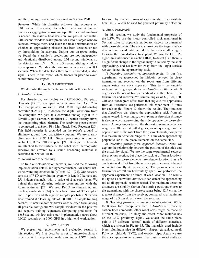
1) Detecting proximity vs. approach angle: In our firstexperiment, we approached the midpoint between the piezotransmitter and receiver on the robot arm from differentangles using our stick apparatus. This tests the omnidi-rectional sensing capabilities of AuraSense. We denote 0degrees as the orientation perpendicular to the plane of thetransmitter and receiver. We sample angles of 60, 120, 180,240, and 300 degrees offset from that angle to test approachesfrom all directions. We performed this experiment 13 timesfor each angle. Figure 13 shows the results. They indicatethat AuraSense can detect the approaching stick from allangles tested. Interestingly, the maximum detection distanceis shorter when approaching the side opposite the piezo ele-ments. Among angles tested, the shortest maximum detectionrange was 10.9 cm at 120 degrees, an oblique angle on theopposite side of the robot from the piezo elements, comparedto a maximum detection range of 18.3 cm when approachingperpendicular to the piezo elements on the same side.
2) Detecting proximity vs. approach location: Next, weexplore the relationship between the position of the stick andthe proximity signal. We use the same experimental setup asthe previous section, but place the stick at different locationsrelative to the piezo elements. We denote location 0 as a 0cm horizontal offset from the receiver piezo element (the rodis pointed directly at the receiver). The piezo receiver andtransmitter are 20 cm horizontally apart. We performed theapproach experiment 13 times at each location. The resultsin Figure 14 show that AuraSense can detect the approachingrod at all approach locations tested. The maximum detectiondistances are slightly shorter for starting positions closer tothe transmitter, with the shortest range being 12.9 cm at thegreatest distance from the receiver, compared to a maximumrange of 18.3 cm directly over the receiver.
3) Detecting proximity vs. dummy robot material: Whilethe Kinova Jaco manipulator used in AuraSense is made ofcarbon fiber composite, other robot arms might be made ofdifferent materials. To study the effect robot material hason the LSW proximity signal, we attach the same piezopair to 17 different “robots” made of different materials,which are shown in Figure 15. The materials used includebrass, aluminum pipe in different shapes, galvanized steel,Polyvinyl chloride (PVC), and wooden pipe. Again we usethe stick apparatus to approach the dummy robot surfaces.
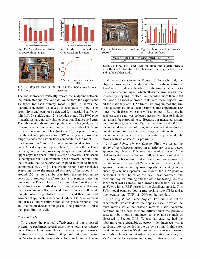
Fig. 13. Max detection distancevs. approaching angle.
Fig. 14. Max detection distancevs. approaching location.
Fig. 15. Materials we used as“robots” .
Fig. 16. Max detection distancevs. “robot” surfaces.
Fig. 17. Objects used in thefield study.
Fig. 18. The ROC curve for ourdetector.
The rod approaches vertically toward the midpoint betweenthe transmitter and receiver pair. We perform the experiment13 times for each dummy robot. Figure 16 shows themaximum detection distances for each dummy robot. Theproximity signal can not be detected for material 4 (a floppythin foil), 7 (a stick), and 12 (a wooden plate). The PVC pipe(material 2) has a notably shorter detection distance (6.5 cm).The other materials we tested produce an LSW signal, with amaximum detection distance among all materials of 37.3 cmfrom a thin aluminum plate (material 13). In practice, mostmetals and rigid plastics allow LSW sensing at a reasonablerange, as does the carbon fiber composite on the robot.
4) Speed limitations: Given a maximum detection dis-tance D and a system response time td (from both mechani-cal delay and system processing delay), we can calculate anupper approach speed limit vmax for AuraSense. This speedis the highest relative movement speed between the robot andthe obstacle that AuraSense can respond to prior to impact,compared as vmax = D
td. The system response time includes
everything up to the measured full stop of the robot, td, isaround 150 ms. As can be seen from the previous microbenchmark studies, AuraSense has a maximum detectionrange on the Kinova Jaco of 18.3 cm. Therefore the upperspeed limit for our testbed is 122 cm/s, which is well abovethe maximum end effector speed of our robot arm (20 cm/s),though fast-moving obstacles could exceed this limit, andadversarial approach vectors could reduce it to 72 cm/s basedon our tests. Future optimization of the system response timeand maximum detection range could be performed to raisethe speed limit as well.
B. Field Study
To evaluate the practical effectiveness of our proposedsystem, we performed several experiments testing AuraSenseon a Kinova Jaco manipulator to assess the performanceof AuraSense in a realistic setting. We tested AuraSenseon 24 objects with various dielectrics, including a human
Static Object TPR Moving Object TPR TNR100% 95.3% 99.1%
TABLE I. Final TPR and TNR for static and mobile objectswith the CNN classifier. The robot arm is moving for both staticand mobile object trials.
hand, which are shown in Figure 17. In each trial, theobject approaches and collides with the arm- the objective ofAuraSense is to detect the object in the time window 0.5 to0.2 seconds before impact, which allows the arm enough timeto react by stopping in place. We recorded more than 2000real world on-robot approach trials with these objects. Wehit the stationary arm 1152 times; we programmed the armto hit a stationary object, and performed that experiment 120times; we hit the moving arm with an object 1152 times. Ineach case, the data was collected across two days to includevariation in background noise. Because our measured systemresponse time td is around 150 ms, we truncate the 0.5-0.2second window before collision, and consider that window asone datapoint. We also collected negative datapoints in 0.3second windows where the arm is stationary or randomlymoves with no obstacles in proximity.
1) Static Robot, Moving Object: First, we tested theability of AuraSense mounted on a stationary arm to detectapproaching objects. This test case avoids many of thechallenges described in Section III-B, such as channel distur-bance from robot motion, and self-detection. We approachedthe stationary arm with all 24 objects with diverse angles,approach locations, and approach speeds deliberately intro-duced by a human operator. We divided the 1152 positivedatapoints in half based on the day it was collected, andused one day for training and the other for testing. As thisexperiment lacks complex non-linear noise factors, we usedan SVM with an RBF kernel for the classification task. ThisSVM model obtained both a true positive rate (TPR) and atrue negative rate (TNR) of 100% on the test data.
2) Moving Robot, Static Object: For our next set ofexperiments, we considered the opposite case, in which therobot moves while the obstacle remains static. Accuratedetection in this case is more difficult than the previouscase, as robot motion introduces complex noise signals asdiscussed in Section III-B. To test this case, we had therobot move on a repeatable trajectory which intersects with acardboard box suspended in the air by a string. In this case,the 0.3 second window SVM classifier performs much worse,and only achieves an inter-day generalization accuracy of75.8%, due to the variation in the signal introduced by robot
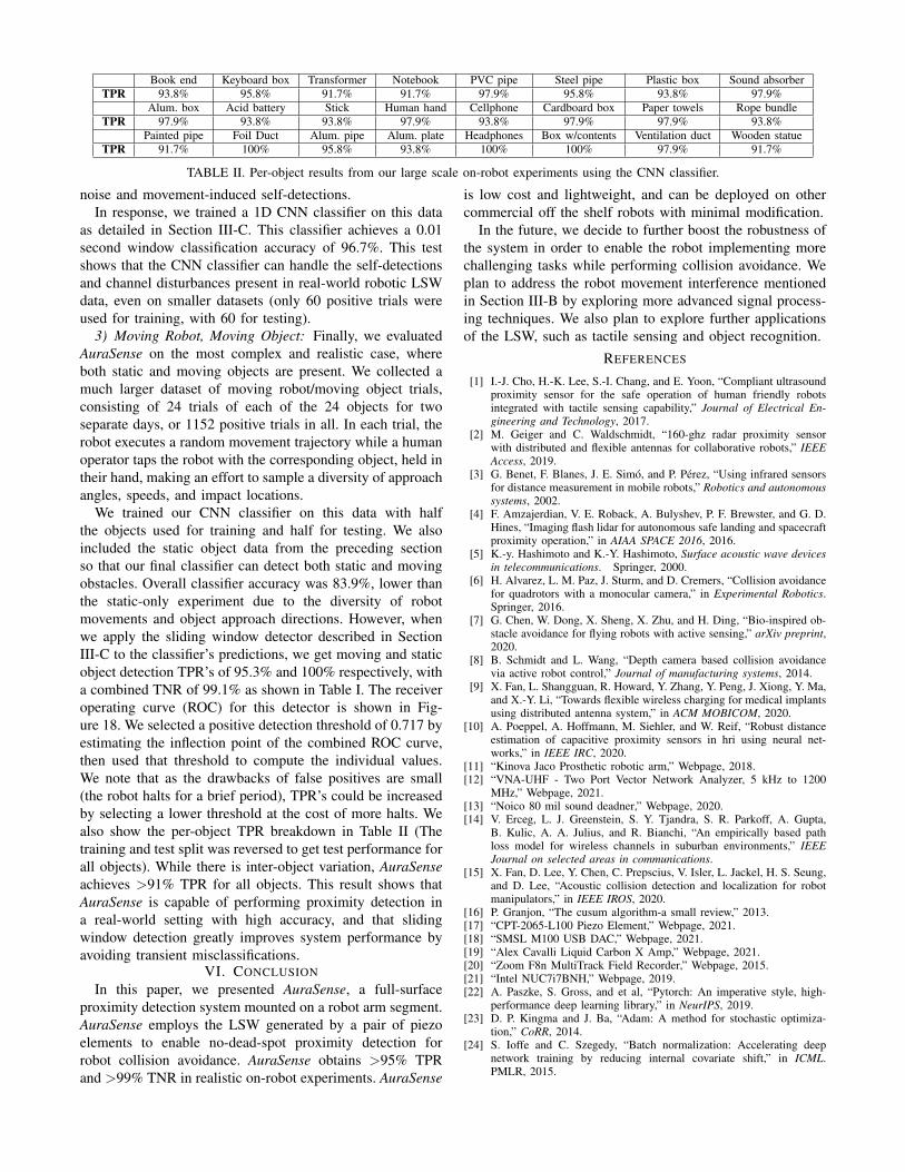
Book end Keyboard box Transformer Notebook PVC pipe Steel pipe Plastic box Sound absorberTPR 93.8% 95.8% 91.7% 91.7% 97.9% 95.8% 93.8% 97.9%
Alum. box Acid battery Stick Human hand Cellphone Cardboard box Paper towels Rope bundleTPR 97.9% 93.8% 93.8% 97.9% 93.8% 97.9% 97.9% 93.8%
Painted pipe Foil Duct Alum. pipe Alum. plate Headphones Box w/contents Ventilation duct Wooden statueTPR 91.7% 100% 95.8% 93.8% 100% 100% 97.9% 91.7%
TABLE II. Per-object results from our large scale on-robot experiments using the CNN classifier.
noise and movement-induced self-detections.In response, we trained a 1D CNN classifier on this data
as detailed in Section III-C. This classifier achieves a 0.01second window classification accuracy of 96.7%. This testshows that the CNN classifier can handle the self-detectionsand channel disturbances present in real-world robotic LSWdata, even on smaller datasets (only 60 positive trials wereused for training, with 60 for testing).
3) Moving Robot, Moving Object: Finally, we evaluatedAuraSense on the most complex and realistic case, whereboth static and moving objects are present. We collected amuch larger dataset of moving robot/moving object trials,consisting of 24 trials of each of the 24 objects for twoseparate days, or 1152 positive trials in all. In each trial, therobot executes a random movement trajectory while a humanoperator taps the robot with the corresponding object, held intheir hand, making an effort to sample a diversity of approachangles, speeds, and impact locations.
We trained our CNN classifier on this data with halfthe objects used for training and half for testing. We alsoincluded the static object data from the preceding sectionso that our final classifier can detect both static and movingobstacles. Overall classifier accuracy was 83.9%, lower thanthe static-only experiment due to the diversity of robotmovements and object approach directions. However, whenwe apply the sliding window detector described in SectionIII-C to the classifier’s predictions, we get moving and staticobject detection TPR’s of 95.3% and 100% respectively, witha combined TNR of 99.1% as shown in Table I. The receiveroperating curve (ROC) for this detector is shown in Fig-ure 18. We selected a positive detection threshold of 0.717 byestimating the inflection point of the combined ROC curve,then used that threshold to compute the individual values.We note that as the drawbacks of false positives are small(the robot halts for a brief period), TPR’s could be increasedby selecting a lower threshold at the cost of more halts. Wealso show the per-object TPR breakdown in Table II (Thetraining and test split was reversed to get test performance forall objects). While there is inter-object variation, AuraSenseachieves >91% TPR for all objects. This result shows thatAuraSense is capable of performing proximity detection ina real-world setting with high accuracy, and that slidingwindow detection greatly improves system performance byavoiding transient misclassifications.
VI. CONCLUSION
In this paper, we presented AuraSense, a full-surfaceproximity detection system mounted on a robot arm segment.AuraSense employs the LSW generated by a pair of piezoelements to enable no-dead-spot proximity detection forrobot collision avoidance. AuraSense obtains >95% TPRand >99% TNR in realistic on-robot experiments. AuraSense
is low cost and lightweight, and can be deployed on othercommercial off the shelf robots with minimal modification.
In the future, we decide to further boost the robustness ofthe system in order to enable the robot implementing morechallenging tasks while performing collision avoidance. Weplan to address the robot movement interference mentionedin Section III-B by exploring more advanced signal process-ing techniques. We also plan to explore further applicationsof the LSW, such as tactile sensing and object recognition.
REFERENCES
[1] I.-J. Cho, H.-K. Lee, S.-I. Chang, and E. Yoon, “Compliant ultrasoundproximity sensor for the safe operation of human friendly robotsintegrated with tactile sensing capability,” Journal of Electrical En-gineering and Technology, 2017.
[2] M. Geiger and C. Waldschmidt, “160-ghz radar proximity sensorwith distributed and flexible antennas for collaborative robots,” IEEEAccess, 2019.
[3] G. Benet, F. Blanes, J. E. Simo, and P. Perez, “Using infrared sensorsfor distance measurement in mobile robots,” Robotics and autonomoussystems, 2002.
[4] F. Amzajerdian, V. E. Roback, A. Bulyshev, P. F. Brewster, and G. D.Hines, “Imaging flash lidar for autonomous safe landing and spacecraftproximity operation,” in AIAA SPACE 2016, 2016.
[5] K.-y. Hashimoto and K.-Y. Hashimoto, Surface acoustic wave devicesin telecommunications. Springer, 2000.
[6] H. Alvarez, L. M. Paz, J. Sturm, and D. Cremers, “Collision avoidancefor quadrotors with a monocular camera,” in Experimental Robotics.Springer, 2016.
[7] G. Chen, W. Dong, X. Sheng, X. Zhu, and H. Ding, “Bio-inspired ob-stacle avoidance for flying robots with active sensing,” arXiv preprint,2020.
[8] B. Schmidt and L. Wang, “Depth camera based collision avoidancevia active robot control,” Journal of manufacturing systems, 2014.
[9] X. Fan, L. Shangguan, R. Howard, Y. Zhang, Y. Peng, J. Xiong, Y. Ma,and X.-Y. Li, “Towards flexible wireless charging for medical implantsusing distributed antenna system,” in ACM MOBICOM, 2020.
[10] A. Poeppel, A. Hoffmann, M. Siehler, and W. Reif, “Robust distanceestimation of capacitive proximity sensors in hri using neural net-works,” in IEEE IRC, 2020.
[11] “Kinova Jaco Prosthetic robotic arm,” Webpage, 2018.[12] “VNA-UHF - Two Port Vector Network Analyzer, 5 kHz to 1200
MHz,” Webpage, 2021.[13] “Noico 80 mil sound deadner,” Webpage, 2020.[14] V. Erceg, L. J. Greenstein, S. Y. Tjandra, S. R. Parkoff, A. Gupta,
B. Kulic, A. A. Julius, and R. Bianchi, “An empirically based pathloss model for wireless channels in suburban environments,” IEEEJournal on selected areas in communications.
[15] X. Fan, D. Lee, Y. Chen, C. Prepscius, V. Isler, L. Jackel, H. S. Seung,and D. Lee, “Acoustic collision detection and localization for robotmanipulators,” in IEEE IROS, 2020.
[16] P. Granjon, “The cusum algorithm-a small review,” 2013.[17] “CPT-2065-L100 Piezo Element,” Webpage, 2021.[18] “SMSL M100 USB DAC,” Webpage, 2021.[19] “Alex Cavalli Liquid Carbon X Amp,” Webpage, 2021.[20] “Zoom F8n MultiTrack Field Recorder,” Webpage, 2015.[21] “Intel NUC7i7BNH,” Webpage, 2019.[22] A. Paszke, S. Gross, and et al, “Pytorch: An imperative style, high-
performance deep learning library,” in NeurIPS, 2019.[23] D. P. Kingma and J. Ba, “Adam: A method for stochastic optimiza-
tion,” CoRR, 2014.[24] S. Ioffe and C. Szegedy, “Batch normalization: Accelerating deep
network training by reducing internal covariate shift,” in ICML.PMLR, 2015.