automated generation of failure modes and effects analyses … · 2012-05-22 · motivation •...
TRANSCRIPT

Automated Generation of Failure Modes and Effects Analyses from AADL Architectural and Error Models
Myron Hecht, Alexander Lam, Russell Howes, and Christopher Vogl, The Aerospace Corporationp p
Presented toSystems and Software Technology Conference
Salt Lake, City, UTApril 2010
© The Aerospace Corporation 2010
April, 2010

Report Documentation Page Form ApprovedOMB No. 0704-0188
Public reporting burden for the collection of information is estimated to average 1 hour per response, including the time for reviewing instructions, searching existing data sources, gathering andmaintaining the data needed, and completing and reviewing the collection of information. Send comments regarding this burden estimate or any other aspect of this collection of information,including suggestions for reducing this burden, to Washington Headquarters Services, Directorate for Information Operations and Reports, 1215 Jefferson Davis Highway, Suite 1204, ArlingtonVA 22202-4302. Respondents should be aware that notwithstanding any other provision of law, no person shall be subject to a penalty for failing to comply with a collection of information if itdoes not display a currently valid OMB control number.
1. REPORT DATE APR 2010 2. REPORT TYPE
3. DATES COVERED 00-00-2010 to 00-00-2010
4. TITLE AND SUBTITLE Automated Generation of Failure Modes and Effects Analyses fromAADL Architectural and Error Models
5a. CONTRACT NUMBER
5b. GRANT NUMBER
5c. PROGRAM ELEMENT NUMBER
6. AUTHOR(S) 5d. PROJECT NUMBER
5e. TASK NUMBER
5f. WORK UNIT NUMBER
7. PERFORMING ORGANIZATION NAME(S) AND ADDRESS(ES) The Aerospace Corporation,2310 E. El Segundo Blvd,El Segundo ,CA,90245-4609
8. PERFORMING ORGANIZATIONREPORT NUMBER
9. SPONSORING/MONITORING AGENCY NAME(S) AND ADDRESS(ES) 10. SPONSOR/MONITOR’S ACRONYM(S)
11. SPONSOR/MONITOR’S REPORT NUMBER(S)
12. DISTRIBUTION/AVAILABILITY STATEMENT Approved for public release; distribution unlimited
13. SUPPLEMENTARY NOTES Presented at the 22nd Systems and Software Technology Conference (SSTC), 26-29 April 2010, Salt LakeCity, UT. Sponsored in part by the USAF. U.S. Government or Federal Rights License
14. ABSTRACT
15. SUBJECT TERMS
16. SECURITY CLASSIFICATION OF: 17. LIMITATION OF ABSTRACT Same as
Report (SAR)
18. NUMBEROF PAGES
25
19a. NAME OFRESPONSIBLE PERSON
a. REPORT unclassified
b. ABSTRACT unclassified
c. THIS PAGE unclassified
Standard Form 298 (Rev. 8-98) Prescribed by ANSI Std Z39-18

Outline
• Motivation• Background on FMEAs• Introduction to AADL• AADL E M d l A• AADL Error Model Annex• Tool Set for Analyzing Risk and Reliability/Availability• Automated FMEA Generation Example• Additional Discussion• Conclusions
2

Motivation
• Failure Modes and Effects Analyses (and related Criticality Analyses) are rigorous and comprehensive reliability and safety design evaluationsevaluations
– Generally required either by industry standards or Government policies– A fundamental element of defense in many product liability lawsuits
• When performed manually, FMEAs are usually done only once during the detailed design phase because of cost and schedule constraints
– Labor intensive– Labor intensive– Require senior level; analysts
• If automated, FMEAs would have significant benefits– Multiple iterations from conceptual to detailed design– Enables early identification of potential problems
• Single points of failureSingle points of failure• Unanticipated effects
– Facilitates tradeoff studies and evaluations of alternatives
3

Failure Modes and Effects Analysis (FMEA)• Purpose
– To determine the effect of hardware and software failures upon the system and equipment failuresand equipment failures. • Classify effects by impact on mission success and personnel/equipment
safety.Id tif i l i t f f il• Identify single points of failure
• History– First defined as Military Procedure MIL-P-1629, “Procedures for PerformingFirst defined as Military Procedure MIL P 1629, Procedures for Performing
a Failure Mode, Effects and Criticality Analysis”, November 1949.– Further developed and applied by NASA in the 1960’s to improve and verify
reliability of space program hardware.– Since the 1980s, a standard of practice in a wide variety of industries
• DoD: MIL-STD-1629A • Industrial: IEC 60812 (1985)• Industrial: IEC 60812 (1985) • Aviation: SAE ARP 5580 (2001) • Automotive: SAE J1739 (2002) • Space: ECSS-Q-30-02A
4
Space: ECSS Q 30 02A
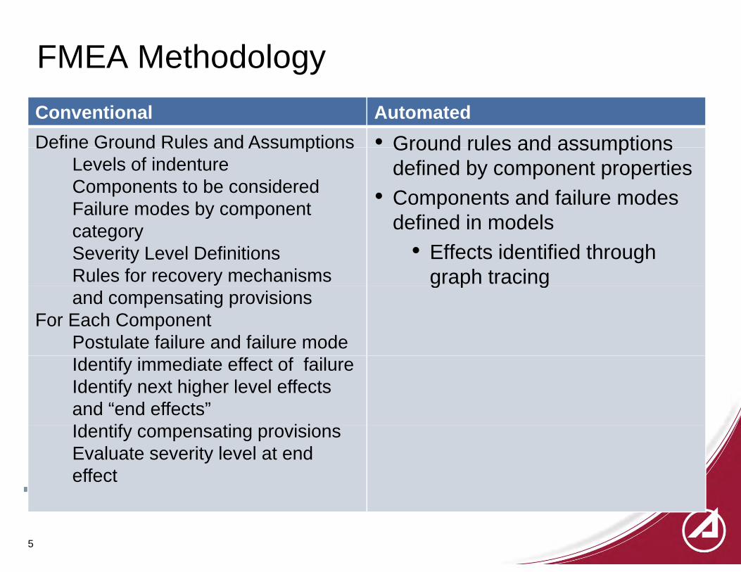
FMEA MethodologyConventional AutomatedDefine Ground Rules and Assumptions • Ground rules and assumptionsDefine Ground Rules and Assumptions
Levels of indentureComponents to be consideredFailure modes by component
Ground rules and assumptions defined by component properties
• Components and failure modes d fi d i d l
y pcategorySeverity Level DefinitionsRules for recovery mechanisms
defined in models• Effects identified through
graph tracingand compensating provisions
For Each ComponentPostulate failure and failure mode
g p g
Identify immediate effect of failureIdentify next higher level effects and “end effects”Id tif ti i iIdentify compensating provisionsEvaluate severity level at end effect
5

FMEA OutputIn Either Worksheet or Tabular Format…
• Identification: Failure Mode identification. • Item: For software, a process in its context.• Failure Mode:
– Immediate Effect: – Intermediate Effect: Second level effect.
• Operator• External networks • Database• Recovery
– End Effect:• System Level (e.g., Individual satellites or the constellation through TT&C functions)• Payload performancey p• Data to outside users through terrestrial interfaces
• Existing Mitigations: Any existing mitigations present in the architecture or design were identified.
• Severity level:• Severity level: – Set under assumption that existing mitigations assumed to work
• Comments:– Additional comments documenting assumptions and uncertainties.
6
Additional comments documenting assumptions and uncertainties.
Introduction to the Architecture Analysis & D i L (AADL)& Design Language (AADL)
• Society of Automotive Engineers (SAE) Aerospace Standard AS5506 y g ( ) p(2004)
– Preceded by more than a decade of development under the DARPA Meta-H programp g
• Provides a standardized textual and graphical notation for describing software and hardware system architectures and their functional interfaces
– architectures (using standard language).– expected program behavior (using behavior annex)– Failure and recovery behavior (using error annex)Failure and recovery behavior (using error annex)
7

AADL vs. other OMG Languages for Stochastic Analysis f Ri k d R li bilitof Risk and Reliability
• AdvantagesAdvantages– Objects directly represent real-time system hardware and software– Standard method for incorporation of quantitative attributes
F il d R P b bili ti Di t ib ti• Failure and Recovery Probabilistic Distributions• Parameters of those distributions• Probabilities and rates for individual transitions
– Standard methods for representing propagation of failures across multiple components• Event ports for failure propagationsEvent ports for failure propagations• Guards to enable conditional propagations (important for abstractions
and reuse)• D b k• Drawbacks
– No commercial quality tools• Public domain tools are available and usable – but not bug free
8

AADL Components (graphical representation)
– text and xml representations also defined
9

AADL Error Model Annex
• AADL annex that supports stochastic analysisAADL annex that supports stochastic analysis• Defines error model
– State transition diagram that represents normal and failed states– Error models can be associated with hardware components, software
components, connections, and “system” (composite) components• Error model consists of
– State definitions– Propagations from and to other components
Probability distribution and parameter definitions– Probability distribution and parameter definitions– Allowed state transitions and probabilities
10

Enabling Features of AADL
• Standard representation of architecture and error modelsStandard representation of architecture and error models• Representation of failure propagation through system
componentscomponents– Event Ports– Guards– Propagations
• Error Model properties– Working status of states– Descriptive information for initial states, effects (subsequent
states) and failure modes (transitions)states), and failure modes (transitions)– Initial states– Terminal States

AADL Error Model Example Faailvisible (in
error model examplefeatures
n)
featuresErrorFree: initial error state;Failed: error state;Fail: error event {Occurrence => poisson lambda};Repair: error event {Occurrence => poisson mu};Failvisible: in out error propagation {Occurrence => fixed p};end example;error model implementation example generalerror model implementation example.generaltransitionsErrorFree-[Fail]->Failed;Failed-[Repair]->ErrorFree; (
ErrorFree-[in Failvisible]->Failed;Failed-[out Failvisible]->Failed;end example.general;
Failvisibleout), prob
12More information: Feiler (2007)
e p

AADL Tool Set
• Eclipse Development Environment (Ganymede) and Eclipse Modeling Framework (EMF)
• Component plug-ins– TopCASED graphical editor to create AADL architecture diagrams (SEI,
Aerospace modifications)Aerospace modifications)– Error Model Editor graphical editor to create AADL error model diagrams
(The Aerospace Corporation newly developed)OSATE AADL t (SEI Th A C ti difi ti )– OSATE AADL generator (SEI, The Aerospace Corporation modifications)
– ADAPT-M Stochastic Petri net to MoBIUS stochastic analysis network tool ((SEI/LAAS Toulouse and The Aerospace Corporation)
– MoBIUS Quantitative Dependability modeling and prediction tool (University of Illinois, Champaign Urbana)
– FMEAGEN FMEA Generator (The Aerospace Corporation newly ( p p ydeveloped)
13

AADL Modeling Tool Chain Data Flow
Qualitative Analysis ChainQualitative Analysis Chain
Quantitative Analysis Chain
14
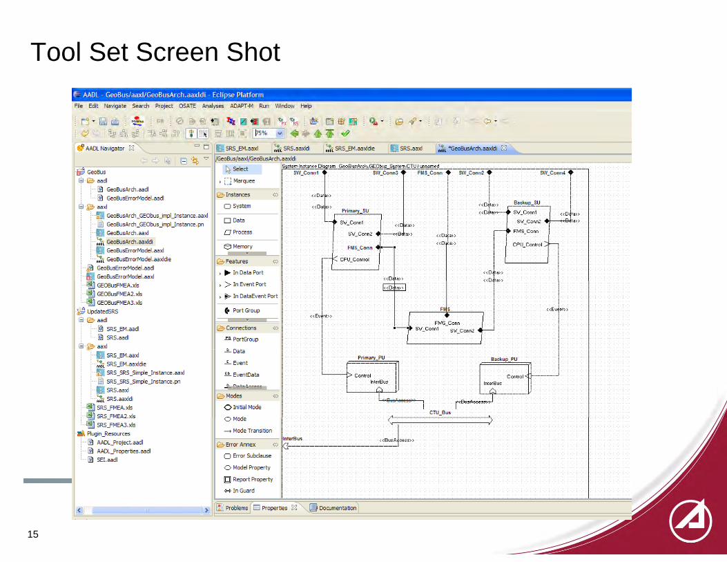
Tool Set Screen Shot
15
~ AADL - GeoBus/aaxl/ GeoBusArch .aaxldi - Eclipse Platform
F~e Edit Navigate Search Project OSATE Analyses ADAPT -M Run Window Help
rj . [g] ~ • ~ ~ ~ ~c. ol' c6~ c~~ c~ ~ 0 c-
.
r ('I AADl Navigator ~ El
<} a ~ ..,.
tJ GeoBus 13 (0. aadl
li!l GeoBusArch. aadl
li!l GeoBusErrorModel.aadl
B/i? aaxl GeoBusArch_GEObus_impi_Instance.aaxl
1£1 GeoBusArch_ GEObus _impi_Instance. pn
R GeoBusArch.aaxl
:!t GeoBusArch. aaxldi
R GeoBusErrorModel.aaxl
:!t GeoBusErrorModel. aaxldie
~ GeoBusErrorModel.aadl
GeoBusErrorModel.aaxl
~ GEOBusFMEA.xls
~ GEOBusFMEA2.xls
~ GEOBusFMEA3.xls
~ UpdatedSRS
13 ~ aadl
li!l SRS_EM.aadl
li!l SRS.aadl
B fi? aaxl
R SRS_EM.aaxl
:!t SRS_EM.aaxldie
SRS_SRS_Simple_lnstance.aaxl
~ SRS_SRS_Simple_lnstance.pn
R SRS.aaxl
:!t SRS.aaxldi
~ SRS_FMEA.xls
~ SRS_FMEA2.xls
~ SRS_FMEA3.xls
a\ Plugin_Resources
li!l AADL_Project.aadl
li!l AADI._Properties.aadl
li!l SEI.aadl
~PX *"'Rs 1"~-5%-v-.,1 ~
SRS_EM.aaxl :!t SRS.aaxldi
/GeoBusfaaxi/GeoBusArch.aaxldi
:!t SRS_EM.aaxldie SRS.aaxl :l._ '"GeoBusArch.aaxldi .!:3
~ Select ~~!...'iiJ~~~!...~~~~.§~~!!:~~~ru-flm~~~rn Cl!:ll.i!!:!~!!!~--------------------------------! SW_Conn1 { SW_Conn:l AIS_Conn + SW_Conu2 ' SW_Coun4 •
• r-~ Marquee I I I L-+ - ! ! I ~Instances <:> ! « !:lit » ! I
! I) 1 Backup SU I 0 System i « Da » « 1ta» r----~--~1 ! I Pn ma_ry_SlJ «0~~-l S\J_Co nn1 «D~ta»
- « ta» 1 0 Data ~ Sw Co nn1 I S\,/_Cor.n~ ta»
0 Process S'w'_Conn2 ~---~a ta» r- FMS_Conn I - -------- I « D•J » ! I
0 Memory
(0. Fe a lures
, .... In Data Port
, > In Event Port
, ~ In DataEvent Port
t PortGroup
.!!l. PortGroup
.l. Data
_. Mode Transition l i
I Fl.IS Conn · - · I u_ ~ontrol I - I I
« D '•» ' CP C ! i ! i r-t CPU_Contlol ! I
I «D1"" I « 0 VI>'~- « D1ta» I ! I i I !
I i I i
«E·J~nl~> I I FMS Conn I I •- j· SV_Conn1 - S\,/_Cono2
I ~,====~~==~ ~Ccntlol
· fn:erBus !
1.--·9 ··--··--··-··
~ CTU_Dus
I
I !
« E..,.,r-t»
i ! i
I -~·--··_J
! 1---------- ilnterBu<ii
wic----(0. Error Annex
0 Error Subclause
0 Model Property
I!J Report Property
** In Guard 1
< 1 > ft Problems ( Ll Proper~ bj Documentation
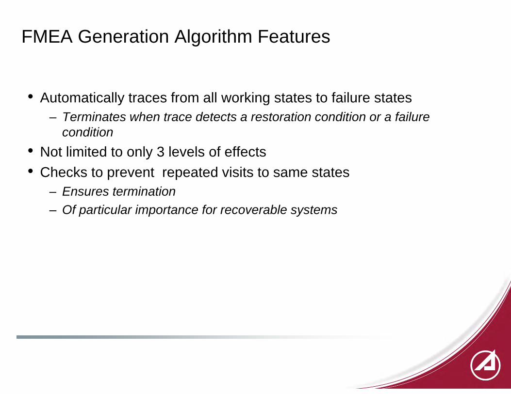
FMEA Generation Algorithm Features
• Automatically traces from all working states to failure statesAutomatically traces from all working states to failure states– Terminates when trace detects a restoration condition or a failure
condition• Not limited to only 3 levels of effects• Not limited to only 3 levels of effects• Checks to prevent repeated visits to same states
– Ensures termination– Of particular importance for recoverable systems

Example: Supplemental Restraint System
Architectural Model
Error Models
Accelerometer ControiUnit
<<Event>> outPort ,:::_ > inPort outPort ,:::_
> Failure
>Failure ~ <l SensorFail
C> SensorFail
Fail re
\
---~ rFail
Airbag
<<Event>>
> inPort
I> IncomingFail a \__/
I
I I I I I
Incom gFail

GenerationGeneration of FMEA f P t ifrom Petri Net of Error Models

Results: Automatically Generated FMEA
Enhanced formatting for presentation purposes

More Complex E M d lError Model
20

Results: Automatically Generated FMEAID Item Initial Failure
Mode 1st Level Effect Transition 2nd Level Effect Transition 3rd Level Effect Transition 4th Level Effect Transition 5th Level Effect
1.1 SBCU.Primary_SU Failure SU.SBCU_Primary ReportDown SBCUSdown from SBCU.Primary_SU to SBCU.Primary_SU SU.SBCU_Primary Down Failure_case_Minor from SBCU.Primary_SU to
SBCU.Primary_SU SU.SBCU_Primary DownMinor RecoverMinor from SBCU.Primary_SU to SBCU.Primary_SU SU.SBCU_Primary ReportRecover SBCUSrecover from SBCU.Primary_SU to
SBCU.Primary_SU SU.SBCU_Primary HotStandby
SBCUSrecover from SBCU.Primary_SU to SBCU.FMS FMS.SBCU UsingPrimary
1.2.1 SBCU.FMS guardin PrimaryDown from SBCU.Primary_SU to SBCU.FMS FMS.SBCU PrimaryisDown
1.2.2.1 Failure_case_Major from SBCU.Primary_SU to SBCU.Primary_SU SU.SBCU_Primary DownMajor RecoverMajor from SBCU.Primary_SU to
SBCU.Primary_SU SU.SBCU_Primary ReportRecover SBCUSrecover from SBCU.Primary_SU to SBCU.Primary_SU SU.SBCU_Primary HotStandby
1.2.2.2 SBCUSrecover from SBCU.Primary_SU to SBCU.FMS FMS.SBCU UsingPrimary
1.3 SBCU.FMS guardin PrimaryDown from SBCU.Primary_SU to SBCU.FMS FMS.SBCU PrimaryisDown
2.1.1 SBCU.Backup_SU Failure SU.SBCU_Backup ReportDown SBCUSdown from SBCU.Backup_SU to SBCU.Backup_SU SU.SBCU_Backup Down Failure_case_Minor from SBCU.Backup_SU to
SBCU.Backup_SU SU.SBCU_Backup DownMinor RecoverMinor from SBCU.Backup_SU to SBCU.Backup_SU SU.SBCU_Backup ReportRecover SBCUSrecover from SBCU.Backup_SU to
SBCU.Backup_SU SU.SBCU_Backup HotStandby
2.1.2 SBCUSrecover from SBCU.Backup_SU to SBCU.FMS FMS.SBCU UsingBackup
2.2 SBCU.FMS guardin BackupDown from SBCU.Backup_SU to SBCU.FMS FMS.SBCU Down
2.3 SPCU.FMS guardin BusDown from SBCU.FMS to SPCU.FMS FMS.SPCU WaitingForBus
2.4 SPCU.Primary_SU guardin FMSstandby from SPCU.FMS to SPCU.Primary_SU SU.SPCU_Primary ColdStandby
2 5 1 Failure case Major from SBCU.Backup SU to SU SBCU Backup DownMajor RecoverMajor from SBCU.Backup SU to SU SBCU Backup ReportRecover SBCUSrecover from SBCU.Backup SU to SU SBCU Backup HotStandby2.5.1 _ _ j p_SBCU.Backup_SU SU.SBCU_Backup DownMajor j p_
SBCU.Backup_SU SU.SBCU_Backup ReportRecover p_SBCU.Backup_SU SU.SBCU_Backup HotStandby
2.5.2 SBCUSrecover from SBCU.Backup_SU to SBCU.FMS FMS.SBCU UsingBackup
2.6 SBCU.FMS guardin BackupDown from SBCU.Backup_SU to SBCU.FMS FMS.SBCU Down
2.7 SPCU.FMS guardin BusDown from SBCU.FMS to SPCU.FMS FMS.SPCU WaitingForBus
2.8 SPCU.Primary_SU guardin FMSstandby from SPCU.FMS to SPCU.Primary_SU SU.SPCU_Primary ColdStandby
3.1 SBCU.Primary_PU Failure PU.SBCU Terminated CPUfail from SBCU.Primary_PU to SBCU.Primary_SU SU.SBCU_Primary Terminated
3.2 SBCU.FMS guardin PrimaryTerminated from SBCU.Primary_SU to SBCU.FMS FMS.SBCU PrimaryisTerminated
4.1 SBCU.Backup_PU Failure PU.SBCU Terminated CPUfail from SBCU.Backup_PU to SBCU.Backup_SU SU.SBCU_Backup Terminated
4.2 SBCU.FMS guardin BackupTerminated from SBCU.Backup_SU to SBCU.FMS FMS.SBCU Down
4.3 SPCU.FMS guardin BusDown from SBCU.FMS to SPCU.FMS FMS.SPCU WaitingForBus
4.4 SPCU.Primary_SU guardin FMSstandby from SPCU.FMS to SPCU.Primary_SU SU.SPCU_Primary ColdStandby
5.1 SPCU.Primary_SU Failure SU.SPCU_Primary ReportDown SPCUSdown from SPCU.Primary_SU to SPCU.Primary_SU SU.SPCU_Primary Down Recover from SPCU.Primary_SU to SPCU.Primary_SU SU.SPCU_Primary ReportRecover SPCUSrecover from SPCU.Primary_SU to
SPCU.Primary_SU SU.SPCU_Primary ColdStandby
SPCUSrecover from SPCU.Primary_SU to SPCU.FMS FMS.SPCU UsingPrimary
5.2 SPCU.FMS guardin PrimaryDown from SPCU.Primary_SU to SPCU.FMS FMS.SPCU Down
6 SPCU B k SU F il SU SPCU B k R tD SPCUSdown from SPCU.Backup SU to SU SPCU B k D R f SPCU B k SU t SPCU B k SU SU SPCU B k R tR SPCUSrecover from SPCU.Backup SU to SU SPCU B k C ldSt db6 SPCU.Backup_SU Failure SU.SPCU_Backup ReportDown p_SPCU.Backup_SU SU.SPCU_Backup Down Recover from SPCU.Backup_SU to SPCU.Backup_SU SU.SPCU_Backup ReportRecover p_
SPCU.Backup_SU SU.SPCU_Backup ColdStandby
7.1 SPCU.Primary_SU Failure SU.SPCU_Primary ReportDown SPCUSdown from SPCU.Primary_SU to SPCU.Primary_SU SU.SPCU_Primary Down Recover from SPCU.Primary_SU to SPCU.Primary_SU SU.SPCU_Primary ReportRecover SPCUSrecover from SPCU.Primary_SU to
SPCU.Primary_SU SU.SPCU_Primary ColdStandby
7.2 SPCU.FMS guardin BackupDown from SPCU.Backup_SU to SPCU.FMS FMS.SPCU Down
8.1 SPCU.Primary_PU Failure PU.SPCU Terminated CPUfail from SPCU.Primary_PU to SPCU.Primary_SU SU.SPCU_Primary Terminated
8.2 SPCU.FMS guardin PrimaryTerminated from SPCU.Primary_SU to SPCU.FMS FMS.SPCU PrimaryisTerminated
8.2 CPUfail from SPCU.Primary_PU to SPCU.Primary_SU SU.SPCU_Primary Terminated
8.4 SPCU.FMS guardin PrimaryTerminated from SPCU.Primary_SU to SPCU.FMS FMS.SPCU PrimaryisTerminatedy_
9.1 SPCU.Backup_PU Failure PU.SPCU Terminated CPUfail from SPCU.Backup_PU to SPCU.Backup_SU SU.SPCU_Backup Terminated
9.2 SPCU.FMS guardin BackupTerminated from SPCU.Backup_SU to SPCU.FMS FMS.SPCU Down
9.3 CPUfail from SPCU.Backup_PU to SPCU.Backup_SU SU.SPCU_Backup Terminated
9.4 SPCU.FMS guardin BackupTerminated from SPCU.Backup_SU to SPCU.FMS FMS.SPCU Down
21

Tool Set Capabilities for Quantitative Evaluation
AADL Architecture and Error Models
Mobius Stochastic Analysis Network Model
Results
22

Conclusions
• A new generation tool set for quantitative stochastic analysis and g q yqualitative Failure Modes and Effects Analysis (FMEAs) for space systems is under development
– Based on use of the Architecture Analysis and Design Language (AADL)y g g g ( )– Graphically oriented– Modularized with reusable components
• Automated Generation of FMEA/CA enables multiple iterationsAutomated Generation of FMEA/CA enables multiple iterations analyses throughout all stages of the design
– Allows design alternatives to be evaluated• Strategies for recovering from computing disruptions• Strategies for recovering from computing disruptions• Handling failure propagation and common mode failures
– Enables safety and reliability problems to be identified earlyOf iti l i t t ll d t k h ld• Of critical importance to all users and stakeholders
• Significant economic value where products liability is an issue because of conforming and exceeding standard of care
23

Acronyms
ADAPT: AADL Architectural models to stochastic Petri nets through model Transformation,AADL: Architecture Analysis & Design Language
FMEA: Failure Mode and Effects Analysis
FMEA/CA: FMEA /Criticality Analysis
OSATE: Open Source AADL Tool Environment (Software tool integrated into Eclipse)OSATE: Open Source AADL Tool Environment (Software tool integrated into Eclipse)
SAE: Society of Automotive Engineers
SAN: Stochastic Analysis Network
TOPCASED T lkit I OP f C iti l A li ti & S tE D l tTOPCASED: Toolkit In OPen source for Critical Applications & SystEms Development
24
References• A. Rugina, K. Kanoun, M Kaaniche, “The ADAPT Tool: From AADL Architectural Models to Stochastic Petri Nets
through Model Transformation,” 7th European Dependable Computing Conference (EDCC), Kaunas : Lituanie (2008)• Peter Feiler and Anna Rugina, Dependability Modeling with the Architecture Analysis & Design Language (AADL),
Software Engineering Institute report CMU/SEI-2007-TN-043, July 2007, available from www.sei.cmu.edu• D. D. Deavours, G. Clark, T. Courtney, D. Daly, S. Derisavi, J. M. Doyle, W. H. Sanders, and P. G. Webster, “The
Mobius framework and its implementation,” IEEE Trans. on Soft. Eng., vol. 28, no. 10, pp. 956–969, October 2002.• IEC 60812 (1985) Analysis techniques for system reliability - Procedures for failure mode and effect analysis (FMEA) ,
International Electrotechnical Commission, SAE AS5506 (2004) A St d d A hit t A l i d D i L il bl li f• SAE AS5506 (2004), Aerospace Standard: Architecture Analysis and Design Language available online from www.sae.org
• SAE ARP 5580 (2001) Recommended Failure Modes and Effects Analysis (FMEA) Practices for Non-Automobile Applications, Society of Automotive Engineers, available online from www.sae.org
• SAE J1739 (2002) Potential Failure Mode and Effects Analysis in Design (Design FMEA) and Potential Failure Mode• SAE J1739 (2002) Potential Failure Mode and Effects Analysis in Design (Design FMEA) and Potential Failure Mode and Effects Analysis in Manufacturing and Assembly Processes (Process FMEA) and Effects Analysis for Machinery (Machinery FMEA) , Society of Automotive Engineers, available online from www.sae.org
• SEMATECH (1992) “Failure Modes and Effects Analysis (FMEA): A Guide for Continuous Improvement for the Semiconductor Equipment Industry”, Technology Transfer #92020963B-ENG, available online at http://www.ismi.sematech.org/docubase/abstracts/92020963B-ENG.htm
All trademarks, service marks, and trade names are the property of their respective ownersowners
25