automated single-pipe systems for conveyance and water
TRANSCRIPT
AUTOMATED SINGLE-PIPE SYSTEMS FOR CONVEYANCE
AND WATER DISTRIBUTION
A. S. HumpherysAgricultural Engineer
Snake River Conservation Research CenterKimberly, Idaho
Introduction
An advantage of gated pipe for irrigation is that it can be used both forwater conveyance and water distribution. A single gated pipeline isnormally used for a number of irrigation sets and this requires that onegroup of gates be closed and another opened at each irrigation set change.Since this requires considerable labor, different methods of automationare being developed to minimize the labor requirement. In most automatedgated pipe systems, a separate pipeline is used for conveyance whilethe gated pipe is used only for distributing water to the field. Thesupply pipe is either buried or placed on the surface and has automatedvalves attached to risers or outlets located along its length. Thisconstitutes a double-pipe system.
Several attempts have been made to automate the opening and closing of agroup of gates of one irrigation set so that the gated pipe can be usedas a single-pipe system. Fischbach (1) used both cables and rods connectedto air cylinders to open and close sliding gates in four 30-foot lengthsof 8-inch diameter aluminum pipe. When tested in the field, it wasnecessary to make frequent adjustments because movement caused by temper-ature related expansion, contraction and deflection of the aluminumpipe and the rods or cables changed the gate openings. A separatecylinder for each 12 gates and again for each 3 gates still did not provesatisfactory. He concluded that each gate or opening must be individuallycontrolled rather than tieing them together mechanically.
Reynolds (2) described a single-pipe system, referred to as "miniwai,"which was used to irrigate sugarcane in Hawaii. This system combinedboth the conveyance and distribution functions in one channel or pipe.The concept was originally applied to an open channel but was extended toinclude pipelines also. The pipe or channel had outlets located in itsbottom corresponding to irrigation furrow spacings. A flexible rubbermembrane was used to cover all of the flow openings that comprise oneirrigation set. The-downstream end of the membrane was attached to thepipe at the downstream end of the set while the upper end was attached
- 228-
- 229 -
to a control rod at the upstream end of the set. When actuated by anoperator, such as an air or hydraulic cylinder, the control rod eitherpressed the rubber membrane down so that water could flow over the topof it or raised it so that water could flow beneath it. During irriga-tion, water flowed beneath the membrane and out of the outlets in thebottom of the pipe. When the membrane was lowered, it covered the out-lets and water was conveyed to the next downstream set. The pipe usedin this system was split lengthwise so that the membrane could be instal-led by clamping its side edges between the two pipe half-sections. Thesides of the membrane were attached to the top of the channel in an openchannel system. This was an effective means of automating a single-pipesystem but has not been commercially exploited because of the difficultyof installing the membrane inside the pipe.
Pneumatically controlled outlets for a single-pipe system were used byliaise et al. (2). One such system used a metal transition box containinga miniature air pillow or bladder to control the flow from an Epp-Fly 1type gated opening. When the pillow was inflated, it seated against theoutside of the gate to stop the flow of water.
Another pneumatic valve developed by Payne (2) was installed on gatedpipe in place of conventional manually operated gates. The valve useda miniature hydraulic cylinder and a spring-loaded disc type closure andseat. It extended into the pipeline and opened when the pressurized aircylinder pushed the disc from its seat. This normally closed valve useda spring to return the disc to its seat when the air cylinder wasdepressurized. These valves were also installed in a reinforced butylrubber flexible pipe or tube but neither installation was entirely satis-factory. Perhaps the most successful automated outlet was a pillow-discvalve which was installed at each gated pipe opening. This valve consistedof a miniature pneumatic pillow which, when inflated, forced a discagainst the valve seat to close the valve. The valve was a normally openvalve and automatically opened when the pneumatic pillow was depressurized.Operational problems in the field included erosion at the outlets, insuf-ficient flow adjustment to compensate for variable furrow intake rates,inability to change set size and movement and twisting of erosion controlsocks by the wind. Most of these and other problems associated with allof the systems that have been tested are inherent in automating a furrowirrigation system.
Some of the problems associated with automating gated pipe systems areovercome by the recent development of the cablegation single-pipe systemby Kemper et al. (5). This system is described in another paper to bepresented at this conference.
Equipment and controls are now becoming more readily available for automat-ing existing double-pipe systems having buried pipeline equipped withrisers. However, there is a need and a large potential use for a simple
1Company and trade names are shown for the benefit of the reader anddo not imply endorsement or preferential treatment of the company orproducts noted.

- 230-
low cost means of automating both existing and new single-line gated pipesystems. The three systems described in this paper are further attemptsto automate single-pipe irrigation systems.
Flo-Thru Gated Pipe System
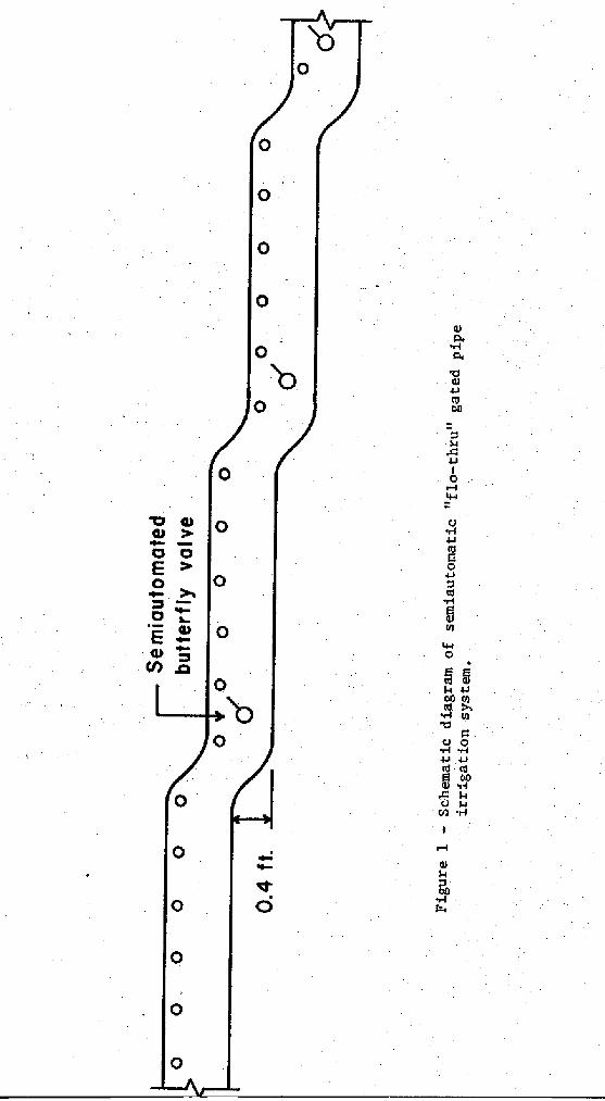
Improvements in irrigation systems are being made in the Grand Valley ofColorado as one component of the Colorado River Basin salinity controlproject. These improvements include the semiautomation of on-farm irri-gation systems. One system used quite extensively since 1979 is the"flow-thru" gated pipe system. This is a single-pipe system designed bytechnicians of the Soil Conservation Service (6,8). The concept, appliedto gated pipe, is an extension of the concrete-lined ported ditch systemwhich is installed on a "stair-step" grade.
System Description
The flo-thru gated pipe system consists of a single gated pipeline instal-led in a series of sections on a stair-step grade at the upper end of afield as shown in Figure 1. Each section comprises one irrigation set andhas a stair-step drop at its lower end. A semiautomatic valve is locateddownstream from the drop. During irrigation, water flows as pipe flowfrom openings in a downstream operating section, and as open channel orfree surface flow in all of the upstream pipe sections or sets.
Design and Operation
Pipe size and slope vary with the field cross slope, available water supplyand furrow stream size. The range of field slopes within which the systemcan be used is approximately 0.004 to 0.02. A minimum slope of about0.004 is necessary to provide the required amount of drop at the end ofeach section. Drop heights are standardized at 0.4 foot as much as pos-sible. However, drops of 0.3 foot are sometimes used with small streams.The flow range for most systems varies from about 0.5 to 1.5 cfs. Systemscan be designed for flows smaller than 0.5 cfs, but farm stream sizes areusually larger than this. Flows larger than 1.5 cfs require larger pipesand steeper field slopes than are usually available.
A program has been developed for a TI-59 calculator to simplify systemdesign (8). Input parameters include supply stream size, furrow streamsize, total length, and total head or elevation difference. The pipe isdesigned so that the free surface flow occupies about 60 to 75% of thepipe cross sectional area. The pipe is placed in the field with thegates approximately 30 degrees from vertical so that the water flowsbeneath the openings as free surface flow for all downstream sets. Thisrequires approximately one increment larger pipe size than would be usedfor a conventional gated pipe system. With the aid of the programmedcalculator, the required pipe diameter and slope and the number of setsare determined for the given field conditions.
0
4cra
arv.
Pd
CI)1JcoOn
Ii
4-1
0
rf
r-I
20
• rf
5COI
4-1
0
g
• +.100
to
U 044 6.44-1 4-1• c0
0054 $4u
•1-o
Ol
$.r
0
0
0
0
0
0
-232-
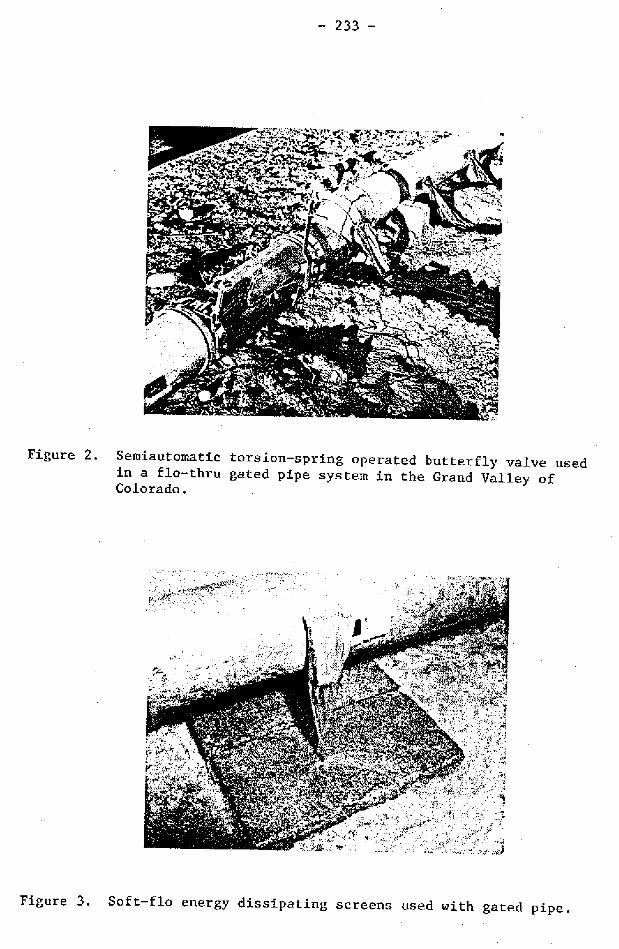
The valve located at each drop either opens or closes to allow irrigationto proceed to the next set in the sequence. The irrigation sequence pro-ceeds in the downstream direction when the valve is of the normally opentype which releases water downstream at the end of its timed period.Irrigation proceeds in the upstream direction if the valve is a normallyclosed type that "checks" the water in the pipeline when it closes at theend of its timed period. Irrigation in the downstream direction with anormally open butterfly valve is preferred. Some of the earlier systemsused a normally closed check valve which created undesirable pressuresurges in the pipeline and caused pipe movement when it closed suddenly.Concrete pillars or pipe supports such as that shown in Figure 2 aredesigned to prevent pipe movement and to maintain pipe grade if the pipeis removed and than later replaced. The pillars are used at each drop,in the center of a section, and as needed so that the distance betweensupports does not exceed 60 feet.
Soil erosion is a problem associated with the pipe gates being locatednear the top of the pipe. An energy dissipating means is needed to pre-vent erosion where streams of emitted water strike the soil surface. Sockssuch as those shown in Figure 2 are often used. However, because of theupturned angle at which they are mounted, they kink, and water sometimescannot flow through them. An alternative practice is to place 5- to 6-footwide plastic sheets on the furrow side of the gated pipe. A more effec-tive method is to use energy dissipating screens 2 located over the gateopening such as that shown in Figure 3.
Valves
A butterfly valve is used at each drop to release water to the nextdownstream set. The valve is preferably located just below the drop, orit may be installed within the drop. Some of the first butterfly valveswere operated with tension springs. However, the improved torsion springoperated valves developed later (4) and shown in Figure 2 are now beingused. A 24-hour mechnical timer is used to trip the valve. Valves in6-, 8-, and 10-inc sizes are now available commercially.3
An automated valve is usually used at the inlet end of the flo-thrusystem to divert water from the supply source into the pipeline. Pneu-matically-operated butterfly valves or water-operated valves (3) may beused for this purpose as well as the spring-operated valves.
Modified Flo-Thru System
A technique similar in principle to the flo-thru gated pipe system is some-times used in the Magic Valley of southern Idaho. Gated pipe is placed
2, 'Softflow" screens are available from Gary McClellan, Rt. 2, Box
303, Vale, Oregon.
3lrrigation Systems Co., Fruita, Colorado 81521.
- 233 -
Figure 2. Semiautomatic torsion-spring operated butterfly valve usedin a flo-thru gated pipe system in the Grand Valley ofColorado.
Figure 3. Soft-flo energy dissipating screens used with gated pipe.
- 234-
in the field with the gates located at the top of the pipe. A homemadepipe-turning tool is used to rotate or roll all of the lengths of pipethat comprise one irrigation set to turn the gates downward. The pipesare rolled or turned slightly different from each other as needed toadjust the amount of flow from the gates. The next set is made by turn-ing the gates downward in the same manner while the gates of the previousset are turned upward to allow water to pass beneath them to the next down-stream set. This procedure is continued to the last set where the gatesin the end pipe length are sometimes turned to the bottom of the pipeso that an end plug is not used. This technique requires less labor tomake an irrigation set than to adjust individual pipe gates. It alsoprevents sediment buildup in the pipes at the end of the line.
Single Pipe with Pneumatically Controlled Outlets
System Description
An experimental 900-foot single-pipe system with pneumatically controlledoutlets was installed in a field near Kimberly, Idaho in 1980. Thissystem, shown in Figure 4, uses 6-, 8-, and 10-inch PVC and fiberglasspipe having one outlet for each two furrows. The outlets are installedin the PVC pipe by first drilling an undersized hole and then using theforming tool shown in Figure 5 to enlarge the hole. The area surroundingthe hole is heated with a heat gun to soften the pipe material beforeinserting the forming tool. The pipe material surrounding the hole formsan inward protruding lip as the hole is enlarged. This lip supports theoutlet pipe and provides a surface contact area for cementing the outletinto the hole. The outlet, a.6-inch long, 111 inch nominal diameter PVCpipe, is inserted into the hole and cemented with an epoxy.
The complete outlet, shown in Figure 6, consists of the outlet pipe withan attached tee, a rubber air pillow or bladder inside the tee, a smallbutterfly flow adjusting valve and corrugated PVC tubing for erosioncontrol. The rectangular miniature air pillows, made special from 11/2-inchdiameter tubing are 5 inches long, with the ends vulcanized closed anda tire inner tube type valve stem attached. The bladders are installedin the tee opposite the side inlet leg of the tee so that when the bladderis inflated, it closes the inlet opening to the tee. For wide furrowspacings, only one side of the tee may be needed while the other side iscapped as shown in Figure 6. All of the outlets comprising one irrigationset are connected in parallel with 1/4-inch O.D. polyethylene air tubing.This size tubing is also used as a manifold line from the compressed airsource to the groups of outlets comprising the individual irrigation sets.Irrigation . proceeds from one set to another in sequence as the air pillowsof one set are exhausted to begin irrigation while those of the precedingset are inflated to terminate irrigation.
Controls
During 1980, the first year that the system was used, an eight horsepowerself-start gasoline engine was used to drive the air compressor and to

- 235-
Figure 4. Single-pipe irrigation system using pneumatically controlledpipe outlets.
Figure 5. Forming tool used to make holes in PVC distribution pipefor discharge outlets.

- 236-
Figure 6. Discharge outlet for single-pipe irrigation system showing abutterfly flow-regulating valve, PVC corrugated tubing usedfor energy dissipation and tubing which supplies air to anair pillow inside the outlet tee.
Figure 7. Photovoltaic solar cell battery charger used to provide powerfor an irrigation controller.
- 237-
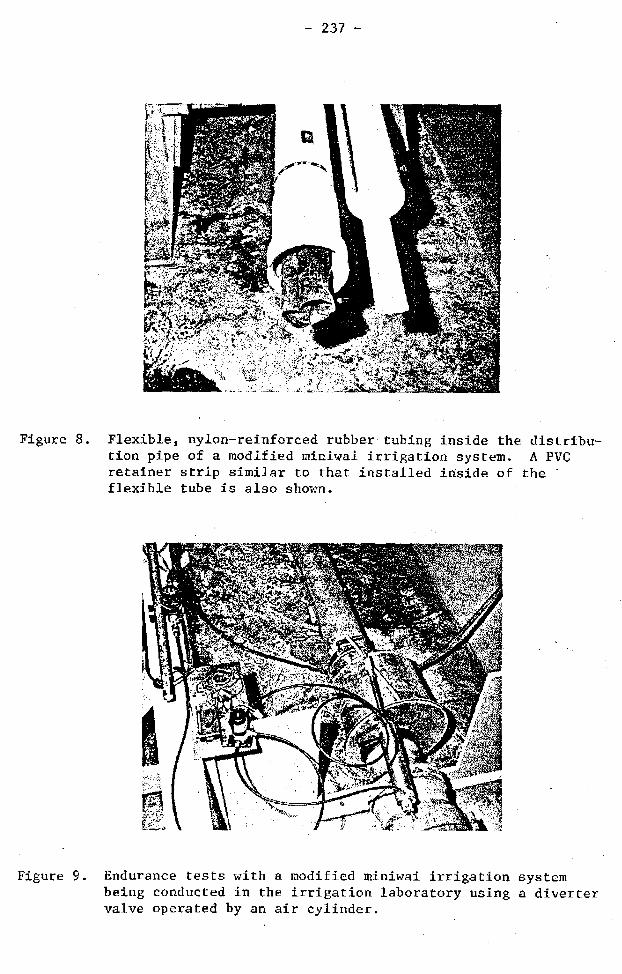
Figure 8. Flexible, nylon-reinforced rubber tubing inside the distribu-tion pipe of a modified miniwai irrigation system. A PVCretainer strip similar to that installed inside of theflexible tube is also shown.
Figure 9. Endurance tests with a modified miniwai irrigation systembeing conducted in the irrigation laboratory using a divertervalve operated by an air cylinder.

- 238 -
charge 12-volt storage batteries used to power the irrigation controller.This was not satisfactory because the self-start engine was unreliable.During 1981, the compressor was located where electrical power is avail-able and is now driven by an electric motor. The photovoltaic solar cellbattery charger shown in Figure 7 was installed to provide power for thesolid state controller located in the field. Air for inflating the airpillows is regulated from 8 to 9 psi.
An experimental, solid state irrigation controller is being developed foruse with this system; however, it is not yet fully operational. Therefore,irrigation set changes were made manually by using a 221/2 volt dry cellbattery to operate the latching solenoid valves which control the airsupply to the pillows of each irrigation set.
gperation
The experimental system has been used for two years with no major problems.None of the air pillows failed during this period. Some difficulty wasexperienced the first year with the latching solenoid valves unlatchingunexpectedly. This was corrected by installing different springs suppliedby the manufacturer.
Because the farmer uses small furrow stream sizes, the butterfly flowregulating valves sometimes became clogged with snails and trash duringthe first year of operation. Since the valves are used for flow regula-tion and are not required to completely shut off the flow, a vee notch wascut in one side of the butterfly disc prior to the 1981 season. The notchwas large enough to discharge most of the required flow while valve adjust-ment provided the balance of the flow needed. The notch provided a wall-to-wall distance large enough to pass debris that was in the water andsolved the clogging problem.
The flexible corrugated tubing attached to each outlet directed the flowinto each furrow and was effective in breaking up the water jet as itemerged from the flow regulating valve so that erosion was effectivelycontrolled.
Modified Miniwai System
System Description
An experimental single-pipe system using the miniwai concept is beingdeveloped.at the Snake River Research Center. Both laboratory and pre-liminary field tests were conducted with prototype systems. Instead ofsplitting a pipe lengthwise as in the original miniwai concept, a nylonreinforced flexible rubber tube is inserted into a conventional gated pipeas shown in Figure 8. Flow is diverted either into, or on the outside of,the flexible tube by a diverter valve. In the irrigation mode, flow isdiverted to the outside of the flexible tube and flows from the gated pipeopenings. When the pipe is used for conveyance, the flow is diverted intothe tube through which it is conveyed to another set or section of pipe.
- 239 -
Flow from gated openings is automatically shut off when water is divertedinto the tube. A diverter valve is installed in the section of pipe atthe upstream end of each set.
The downstream end of the tube is clamped into the pipe so that flow canpass through the tube but not around it at that point. The flexible tubepasses through all of the pipe sections of one irrigation set. A retainerstrip cut lengthwise from a thin-wall PVC pipe is inserted into the tube tohold it to the side of the pipe opposite the flow openings. Otherwise, thetube migrates to the openings and closes them when water is flowing on theoutside of the tube. The retainer strip is fastened to the pipe oppositethe flow openings with pop rivets and "clamps" a portion of the tubebetween it and the wall of the pipe.
Except for endurance tests conducted in the laboratory, the diverter valveswere operated manually during the system's development stage. Eitherpneumatic or spring operators will be used to operate the valves during the1982 field tests.
Laboratory and Field Tests
A number of different diverter valve models were built and tested in the labo-ratory during the process of developing a satisfactory and functional divertervalve. The final prototype valve shown in Figure 9 is relatively simpleand performed well in both laboratory and preliminary field tests. Theprimary element of the valve is a standard female pipe coupling. The tubeis fastened to the downstream end of the coupling and is connected to theupstream inlet pipe when the coupling is positioned so that it fits overthe male end of the inlet pipe.
Two different prototype models were tested in the laboratory after thediverter valve design was finalized. The tests were conducted with bothPVC and aluminum 6-inch gate pipe. An endurance test was conducted withthe aluminum pipe to evaluate the durability of the tube liner with re-peated cycling. We wanted to determine where the wear points are, ifany, and whether the tube would develop leaks near the heads of the poprivets. The system was automatically cycled approximately once everyminute using an air cylinder to operate the diverter valve, Figure 9.The system was cycled 2140 times before failure occurred at the downstreamend where the tube liner was clamped into the pipe. There was no evidenceof wear at any other point on the tube. Failure would have occurred muchlater except that at about 2050 cycles the test was accelerated to hastenfailure by increasing the flow to 1.4 cfs. This is a large flow to dis-tribute through the 17 openings in one 30-foot length of pipe and a smallpressure surge was created at each cycle when the pipe suddenly filled.This would not occur in a full length pipeline.
Preliminary field tests were made with a two-section system totaling 210feet on an experimental plot in 1980 and 1981 to evaluate the concept, totest different diverter valve designs and to evaluate field assembly pro-cedures. The tests using the final diverter valves were very encouraging.The system performed well during three irrigations in 1981 with insignifi-cant leakage from the diverter valves.

-240-
The tests conducted to date are encouraging. One of the disadvantages ofthe system is the amount of labor required for initial assembly. This,however, is a one-time cost, since, once assembled, the system can usuallybe used repeatedly at one location without being moved or disassembled.The potential for this type system is great because of the large acreagein the U.S. that is presently irrigated with gated pipe. These existingsystems can be automated by using the equipment and techniques now beingdeveloped.
Summary
Methods used by previous investigators to automate single-pipe systemsinclude: (1) using air or hydraulic cylinders to actuate cables or rodsconnected to a series of gates comprising one irrigation set, (2) usinga flexible liner to cover gated openings in distribution pipe or channels,and (3) using different types of pneumatically controlled valves onindividual pipe discharge outlets.
Other more recent developments include the flo-thru gated pipe systemwhere gated pipe is installed in a stair-step manner so that water flowsas pipe flow in the irrigating or distribution section of the pipe and asfree surface flow in upstream sections of the pipe. The free water sur-face in open channel flow is below the distribution outlets which arelocated near the top of the pipe. Semiautomatic valves are located ateach stair-step drop.
Another system uses small, lay flat, rectangular air pillows to controlthe flow from individual distribution pipe outlets. Small, butterfly,flow-regulating valves are used on the outlets to control flow dischargeinto individual furrows. A centrally located solid state controllerpowered by solar cells is being developed to control opening and closingof the pneumatic valves in groups that comprise different irrigationsets.
A modified miniwai system is being developed using a flexible rubbertube inside of a length of gated pipe to control flow from all of thedischarge outlets in one irrigation set. A diverter valve has beendeveloped to divert water either into or on the outside of the flexibletube for either conveyance or irrigation from gates or outlets in thepipe.
These systems have a great potential for automating both new and existingpipe systems to conserve both water and energy and to reduce labor.
References
1. Haise, H. R. and P. E. Fischbach. 1970. Auto-mechanization of pipedistribution systems. Proceedings, National Irrigation Symposium,Lincoln, Nebr., November, p. Ml-M15.

- 241-
2. Heise, H. R., E. G. Kruse, M. L. Payne, and H. R. Duke. 1980.Automation of surface irrigation: 15 years of USDA Research andDevelopment at Fort Collins, Col., U.S. Department of Agriculture,Production Research Report No. 179, 60 p.
3. Humpherys, Allan S. 1981. Automated valves for surface irrigationsystems. Paper No. 81-2561 presented at the 1981 ASAE WinterMeeting, Chicago, Ill., Dec. 15-18.
4. Humpherys, A. S., E. Oest and D. A. Young. 1981. Spring-operatedsemiautomatic irrigation valves. Trans. ASAE. (Submitted forpublication.)
5. Kemper, W. D., W. H. Heinemann, D. C. Kincaid and R. V. Worstell.1981. Cablegation: I. Cable controlled plugs in perforated supplypipes for automating furrow irrigation. Trans. ASAE (accepted forpublication).
6. Powers, Allen. USDA-Soil Conservation Service, Yuma, Arizona.Personal communication.
7. Reynolds, William N. 1968. Automatic surface irrigation in Hawaii.In: Automation of Irrigation and Drainage Systems, Proceedingsof the National Irrigation and Drainage Specialty Conference, Amer.Soc. of Civil Engrs., Phoenix, Arizona, November 13-14. pp. 201-218.
8. Torline, Don. USDA-Soil Conservation Service, Grand Junction, Col.Personal communication.