automated substrate cooling system for hvof coating …/media/files/pdf/industries/metals... ·...
TRANSCRIPT

Automated substrate cooling system for HVOF coating operations
Z. Zurecki, R. Ghosh, T. Mebrahtu, M.J. Thayer, and S.R. Stringer, Air Products & Chemicals, Allentown, PA, USA High production rate and feed powder efficiency are critical in the HVOF hardfacing of aircraft landing gear, turbine, and actuator components traditionally electroplated with carcinogenic hard chromium. Desired improvements are hindered by rapid heat build-up in substrate component and thermal expansion mismatch between the carbide coating and steel, titanium or aluminum substrate. A new, cryogenic nitrogen gas (-195
oC) cooling system has
been developed which limits the thermal expansion and substrate softening problems, and enables a non-stop, gun-on-target spraying. Fully automated, the operation of the new AP LIN-Cooling System is based on thermal imaging of the entire substrate and multi-zone cooling with novel, cryofluidic nozzles. Thermal logs and images of components processed are saved by the system for quality auditing purposes. This paper presents results of industrial tests of the system during WC-10Co4Cr coating of Boeing 737 landing gear, demonstrating a 50% reduction in spraying time, corresponding reductions in the consumption of powder and HVOF gases, and additional labor savings due to the use of flexible masking, unfeasible with the traditional cooling methods. Analysis of residual stresses, structures and properties of the coating and AISI 4340 steel substrate shows that the cryogenic nitrogen cooling results in high-quality products.
1 Introduction HVOF technology is known to produce coatings superior to electroplated hard chrome coatings and eliminate releases of toxic hexavalent chromium (Cr
6+)
associated with the latter process. It was quite natural that when EPA and OSHA promulgated stringent rules limiting Cr
6+ emissions, HVOF has been identified as
the best hard-plating substitute by a number of government, academic, and industrial organizations, most prominently the US-Canadian HCAT [1]. To be fully accepted in high-volume/mass-production hardfacing operations, HVOF needs to offer increased throughputs and feed powder utilization efficiencies. This is hindered, primarily, by the heat build-up in the substrate component and temperature control issues. The subject is reviewed in more detail in the next section as it concerns airplane landing gear and the other aerospace components expected to meet fatigue strength specifications.
2 HVOF heat management
Heat input into substrate component is, in most general terms, a function of spraying time, fuel and oxygen flowrates, selected equivalence ratio, i.e. flame stoichiometry, feed powder flowrate, gun-to-surface standoff distance, as well as combustion and gun nozzle characteristics. Typical heat flux into substrate varies between 6 and 8 kW for JetKote spraying guns, 7 and 9 for hydrogen-fuel DJ2600, up to 10 kW for propane-fuel DJ2700, and from 11 to 18 kW for kerosene-fuel JP5000 [2]. Only cooling systems capable of removing these heat fluxes can prevent a local and/or global temperature runaway in more or less massive substrate components. The issue of selecting and maintaining constant substrate temperature during coating operation is critical to HVOF as well as APS and VPS. Typical thermal expansion coefficient of WC-Co is 7 ppm/K while that of high-strength steels most commonly used in aerospace, e.g.: AISI 4340, exceeds 14 ppm/K. Thus, if the substrate is forced to stay at room
temperature during spraying, subject to tension on cooling, the coating tends to crack. If, on the other hand, the substrate is free to overheat during spraying, the coating tends to flake-off on the subsequent cooling due to compressive stress. These effects were examined by Takeda [3] and the later studies. The effect of spraying temperature and the time-at-temperature on thermal degradation of substrate material is just as important. Prior to coating, typical aerospace components are heat treated, e.g.: quenched and tempered at low temperature, which is followed by shot-peening, introducing residual compressive stresses in order to enhance fatigue life. Lee and Su demonstrated that elevated tempering temperature and holding time reduce strength and toughness of AISI 4340 [4]. Holzapfel proposed the Avrami model for quantifying relaxation of the shot-peening resultant residual stress in treated steels [5]:
rs(T,t) /
rso = exp ( -[C exp (-HA / kT) t ]
m) (Eq.1)
where: rs(T,t) is the residual stress after exposing
steel to temperature T during time t, rs
o is the initial
residual stress value, HA is the activation enthalpy, m, C, and k (Boltzmann) are constants. Clearly, minimizing both time and temperature of HVOF spraying helps in preserving substrate properties. Of note, Nascimento compared the effects of chromium plating and HVOF WC-Co coating on fatigue strength of shot-peened AISI 4340 steel to find the spraying more detrimental [6]. We believe that this result was an artifact of experimental procedure where small pin specimens were simply overheated in spraying and prior to the subsequent rotating bending fatigue tests. A consensus has been reached among organizations and companies involved in the evaluation of HVOF for aerospace applications on test and spray deposition procedures [7]. Thus, the substrate for HVOF WC-Co or similar cermet coatings should be preheated to a minimum of 150
oF (66
oC), mainly to drive-off
adsorbates and water. If the substrate is made of Al-alloy, its upper temperature is limited 250
oF (121
oC),
but if this substrate is additionally shot-peened, the
upper limit is reduced to 200oF (93
oC). In case of
steel and Ti-alloy substrates, the upper temperature limit is 350
oF (177
oC) but with shot-peening the
substrate ought to be kept below 300oF (149
oC).
Considering the fact that the carbide coatings are about two times more conductive than the 4340 substrate (~100 W/mK vs. 46 W/mK), and that this thermal conductivity ratio is further doubled in case of Ti-alloy substrates, only effective and precise cooling methods and/or spray pausing assure staying within the outlined temperature limits. Practical temperature control strategies deployed in the field involve a combination of compressed (shop) air cooling, occasionally supplemented with CO2-jets, and inter-pass spray pauses with HVOF gun off the part. Typically, the flow of HVOF gases and feed powder continues during these spraying interruptions in order to prevent subsequent flowrate fluctuations. The combined time of the interruptions ranges usually from 25 to 75 percent of the total spray-coating cycle time in the landing gear hardfacing operations which translates into a significant, 25-75% loss of the feed powder, HVOF gases, labor and booth time.
3 Design of improved cooling system A possibly accurate determination of the temperature over the entire substrate surface during spraying operation is the first step toward protecting the substrate material from time-dependant thermal degradation and minimizing large-scale, interfacial stresses which may lead to cracks or delamination of coating on cooling to room temperature at the end of the operation. This is achieved by the use of thermal imaging camera (2D-IR) or an array of single-point IR-sensors looking at different but more or less uniformly spaced areas over the substrate surface. Averaging these multiple temperature inputs significantly reduces measurement error due to temporal position of HVOF gun, flame blinding, or positioning of cooling nozzles. Temperature sensing from each area, i, is repeated during spraying with preselected frequency, e.g.: 4 Hz, and the temperature averaging can be extended over a number of measurement periods, j. as shown in Eq. 2. This time-geometry averaging method takes into account thermal inertia of the substrate acting as heat sink and smoothens the averages calculated during spray start-ups or when coating extreme edges of the component. Expressed as a percentage of the average temperature Tij, standard deviation of substrate temperatures, Std, is also calculated over the time-geometry input matrix as shown in Eq. 3.
Tavg = (imax jmax)-1
1jmax(1
imax Tij) (Eq.2)
Std = ((imax jmax)-1
1jmax(1
imax Tij2) –Tavg
2)0.5
/Tavg (Eq.3) A PC-based control system compares actual Tij value to the desired target temperature, selected from the range of recommended substrate temperatures, and adjusts the valves of the coolant medium. Plot of Std, along with temperature logs and thermal images
acquired during spraying are saved for post-spray inspection and quality auditing purposes. Large values of Std, e.g.: >30% of Tij, indicate a non-uniform temperature distribution during coating operation, i.e. excessive spatial and temporal thermal stresses. Upon inspection of Std record, HVOF operators may decide if there is a need to modify the process which may include reconfiguration of cooling nozzles, masking, or changing the traverse speed of the gun and powder spray rate.
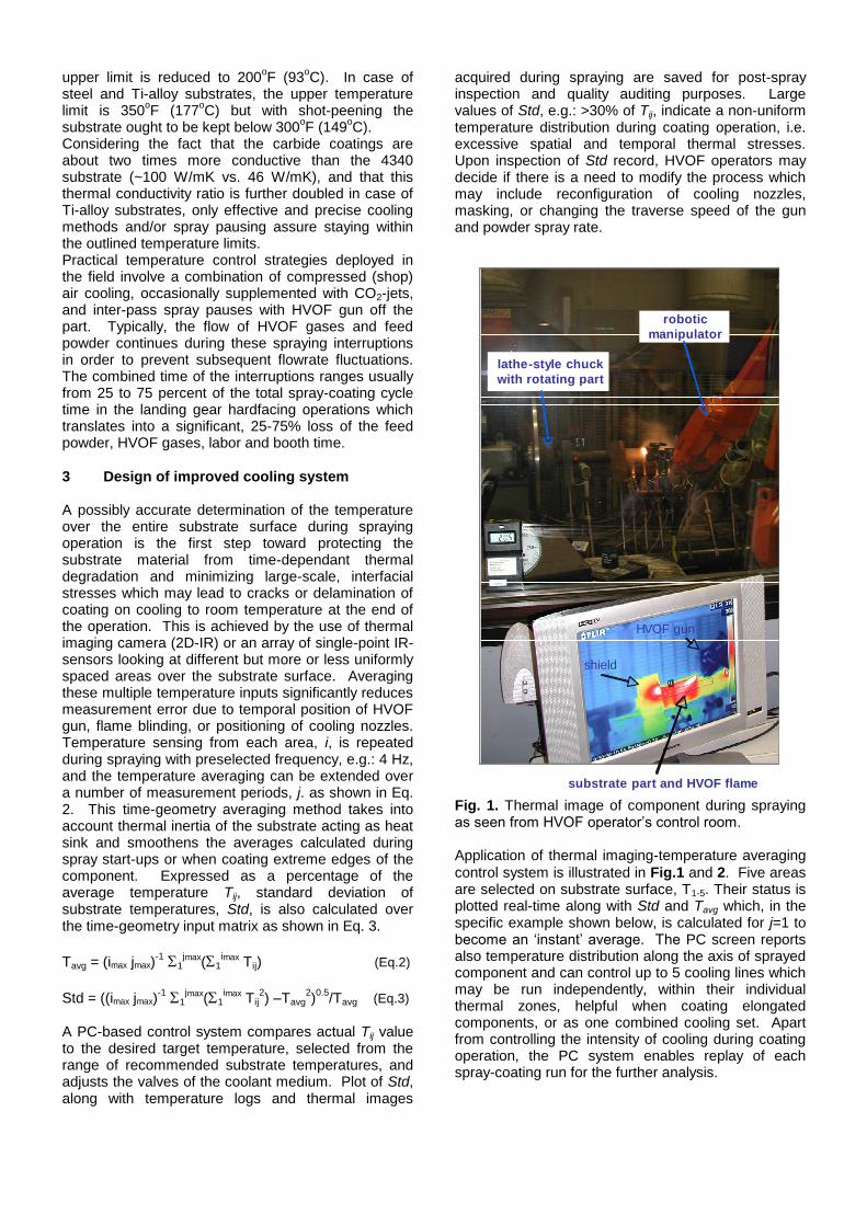
Fig. 1. Thermal image of component during spraying as seen from HVOF operator’s control room. Application of thermal imaging-temperature averaging
control system is illustrated in Fig.1 and 2. Five areas are selected on substrate surface, T1-5. Their status is plotted real-time along with Std and Tavg which, in the specific example shown below, is calculated for j=1 to become an ‘instant’ average. The PC screen reports also temperature distribution along the axis of sprayed component and can control up to 5 cooling lines which may be run independently, within their individual thermal zones, helpful when coating elongated components, or as one combined cooling set. Apart from controlling the intensity of cooling during coating operation, the PC system enables replay of each spray-coating run for the further analysis.
substrate part and HVOF flame
robotic
manipulator
lathe-style chuck
with rotating part
shield
HVOF gun
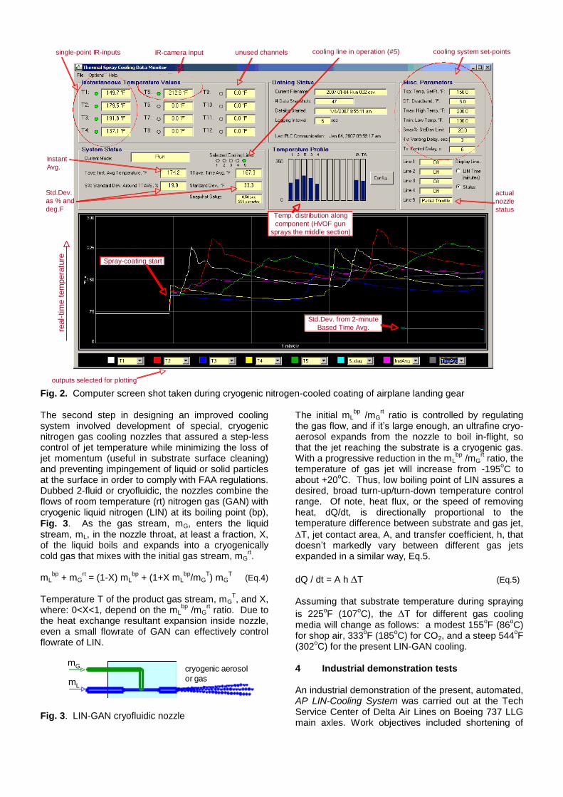
Fig. 2. Computer screen shot taken during cryogenic nitrogen-cooled coating of airplane landing gear The second step in designing an improved cooling system involved development of special, cryogenic nitrogen gas cooling nozzles that assured a step-less control of jet temperature while minimizing the loss of jet momentum (useful in substrate surface cleaning) and preventing impingement of liquid or solid particles at the surface in order to comply with FAA regulations. Dubbed 2-fluid or cryofluidic, the nozzles combine the flows of room temperature (rt) nitrogen gas (GAN) with cryogenic liquid nitrogen (LIN) at its boiling point (bp),
Fig. 3. As the gas stream, mG, enters the liquid stream, mL, in the nozzle throat, at least a fraction, X, of the liquid boils and expands into a cryogenically cold gas that mixes with the initial gas stream, mG
rt.
mL
bp + mG
rt = (1-X) mL
bp + (1+X mL
bp/mG
T) mG
T (Eq.4)
Temperature T of the product gas stream, mG
T, and X,
where: 0<X<1, depend on the mLbp
/mGrt ratio. Due to
the heat exchange resultant expansion inside nozzle, even a small flowrate of GAN can effectively control flowrate of LIN.
Fig. 3. LIN-GAN cryofluidic nozzle
The initial mLbp
/mGrt ratio is controlled by regulating
the gas flow, and if it’s large enough, an ultrafine cryo-aerosol expands from the nozzle to boil in-flight, so that the jet reaching the substrate is a cryogenic gas. With a progressive reduction in the mL
bp /mG
rt ratio, the
temperature of gas jet will increase from -195oC to
about +20oC. Thus, low boiling point of LIN assures a
desired, broad turn-up/turn-down temperature control range. Of note, heat flux, or the speed of removing heat, dQ/dt, is directionally proportional to the temperature difference between substrate and gas jet,
T, jet contact area, A, and transfer coefficient, h, that doesn’t markedly vary between different gas jets expanded in a similar way, Eq.5.
dQ / dt = A h T (Eq.5) Assuming that substrate temperature during spraying
is 225oF (107
oC), the T for different gas cooling
media will change as follows: a modest 155oF (86
oC)
for shop air, 333oF (185
oC) for CO2, and a steep 544
oF
(302oC) for the present LIN-GAN cooling.
4 Industrial demonstration tests An industrial demonstration of the present, automated, AP LIN-Cooling System was carried out at the Tech Service Center of Delta Air Lines on Boeing 737 LLG main axles. Work objectives included shortening of
single-point IR-inputs IR-camera input unused channels cooling line in operation (#5) cooling system set-points
actual
nozzle
status
Instant
Avg.
Std.Dev.
as % and
deg.FTemp. distribution along
component (HVOF gun
sprays the middle section)
real-
tim
e t
em
pera
ture Spray-coating start
Std.Dev. from 2-minute
Based Time Avg.
outputs selected for plotting
mL
mG cryogenic aerosol
or gas
component coating cycle time and saving feed powder and HVOF gases through elimination of interpass cooling breaks necessitated with the conventional forced air cooling due to its limited cooling capacity. The following conditions were used during HVOF coating of these components with WC-10Co4Cr powder sprayed at the constant rate of 45 grams/min:
DJ2600 gun, 1520 scfh H2-fuel (43 m3/hr) and 476
scfh O2 (13.5 m3/hr) producing about 84 kW of
thermal power at = 1.6 equivalence ratio (fuel-rich flame), spraying at 9-inch standoff (229 mm)
45 inch-long component (1143 mm) rotated to reach 150 ft/min. (45.7 m/min.) substrate surface speed using gun traverse feedrate of 1/8-inch/rev. (3.175 mm/rev.)
Cooling: (a) conventional forced air, jetted from 118 psig (0.8 MPa) using an extended, stationary multi-nozzle air header and (b) one LIN-GAN cryofluidic nozzle attached to robotic manipulator, next to the HVOF gun and jetting from 100/120 psig (0.7/0.8 MPa) and 5-inch standoff (127 mm)
5 IR-sensors (i = 5) were used to monitor temperature of the entire substrate surface during spraying, and their readings, recorded with the frequency of 5 Hz, were averaged over a period of 20 sec. (j = 100).
The conventional, forced air cooling practice (a) was benchmarked against the new cooling practice where
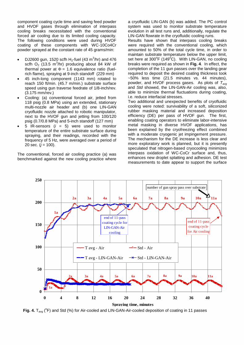
a cryofluidic LIN-GAN (b) was added. The PC control system was used to monitor substrate temperature evolution in all test runs and, additionally, regulate the LIN-GAN flowrate in the cryofluidic cooling runs. Results have shown that interpass cooling breaks were required with the conventional cooling, which amounted to 50% of the total cycle time, in order to maintain substrate temperature below the upper limit, set here at 300
oF (149
oC). With LIN-GAN, no cooling
breaks were required as shown in Fig. 4. In effect, the completion of the 11 gun passes over the landing gear required to deposit the desired coating thickness took ~50% less time (21.5 minutes vs. 44 minutes), powder, and HVOF process gases. As plots of Tavg and Std showed, the LIN-GAN-Air cooling was, also, able to minimize thermal fluctuations during coating, i.e. reduce interfacial stresses. Two additional and unexpected benefits of cryofluidic cooling were noted: survivability of a soft, siliconized rubber masking material and increased deposition efficiency (DE) per pass of HVOF gun. The first, enabling coating operators to eliminate labor-intensive metal masking in diverse HVOF applications, has been explained by the cryofreezing effect combined with a moderate cryogenic jet impingement pressure. The mechanism for the DE increase is less clear and more exploratory work is planned, but it is presently speculated that nitrogen-based cryocooling minimizes interpass oxidation of WC-CoCr surface and, thus, enhances new droplet splatting and adhesion. DE test measurements to date appear to support the surface
0
50
100
150
200
250
0 4 8 12 16 20 24 28 32 36 40
Spraying time, minutes
Tem
pera
ture,
deg
. F
, a
nd
% D
ev
iati
on
.
T avg - Air Std - Air
T avg - LIN-GAN-Air Std - LIN-GAN-Air
3a2a 4a 5a 6a 7a 8a 9a 10a 11a
3a2a 4a 5a 6a 7a 8a 9a 10a 11a
1a
1a
number of gun spray pass over substrate
end of 11-pass
coating cycle
for Air cooling
end of 11-pass
coating cycle for
LIN-GAN-Air
cooling
Fig. 4. Tavg (oF) and Std (%) for Air-cooled and LIN-GAN-Air-cooled deposition of coating in 11 passes
oxidation hypothesis, Table 1.
Table 1: Deposition efficiency vs. cooling
Cooling method: Average coating thickness: Ratio:
(a) Forced Air 0.31 in/pass (7.9 m/pass) 100%
(-) Ambient Air 0.27 in/pass (7.0 m/pass) 88%
(b) LIN-GAN-Air 0.35 in/pass (8.8 m/pass) 111%
4.1 Coating evaluation The forced air (a) and the cryogenically cooled coatings (b) were evaluated by the Delta Air Lines’ quality control laboratory using standard procedures, found to be identical within the measurement error and met all product specifications. The main characteristics of these coatings are as follows: 83-86 MPa bond strength (tensile test), 0.05-0.20% porosity (optical microscope), 1100-1400 HV hardness, and
1.0-1.1 m Ra as-sprayed roughness (stylus test). Additional chemical, structural, and residual stress analysis were run in our laboratory to elucidate effects of cooling. As determined by bulk chemical analysis (Leco) of carbon, oxygen and nitrogen, the LIN-GAN-Air cooling produced the least oxidized coatings,
without nitrogen pick-up, Table 2. Also, the average
microhardness in the 150 m-thick substrate layer immediately under the coating was the highest, i.e. the least thermally softened in the case of LIN-GAN-Air cooling. This result was expected in view Eq.1.
Table 2: Other coating and substrate properties
Cooling method C/O
(ctg.)
N/O
(ctg.)
4340 steel substrate
microhardness, HV
300G
(a) Forced Air 44 0.2 395
(-) Ambient Air 30 0.2 390
(b) LIN-GAN-Air 46 0.2 420
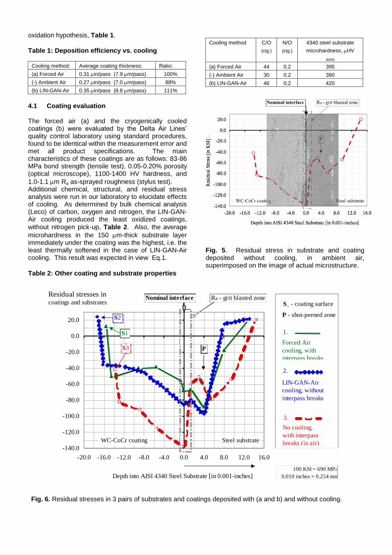
Fig. 5. Residual stress in substrate and coating deposited without cooling, in ambient air, superimposed on the image of actual microstructure.
-140.0
-120.0
-100.0
-80.0
-60.0
-40.0
-20.0
0.0
20.0
-20.0 -16.0 -12.0 -8.0 -4.0 0.0 4.0 8.0 12.0 16.0
Depth into AISI 4340 Steel Substrate [in 0.001-inches]
Res
idual
Str
ess
[in K
SI]
.
1.
Forced Air
cooling, with
interpass breaks
2.
LIN-GAN-Air
cooling, without
interpass breaks
3.
No cooling,
with interpass
breaks (in air)
S_ - coating surface
P - shot-peened zone
S1
S2
S3 P
Nominal interface Ra - grit blasted zone
WC-CoCr coating Steel substrate
Residual stresses incoatings and substrates
100 KSI = 690 MPa
0.010 inches = 0.254 mm
Fig. 6. Residual stresses in 3 pairs of substrates and coatings deposited with (a and b) and without cooling.
Residual stresses were measured across the coatings and substrates using X-ray diffraction and incremental
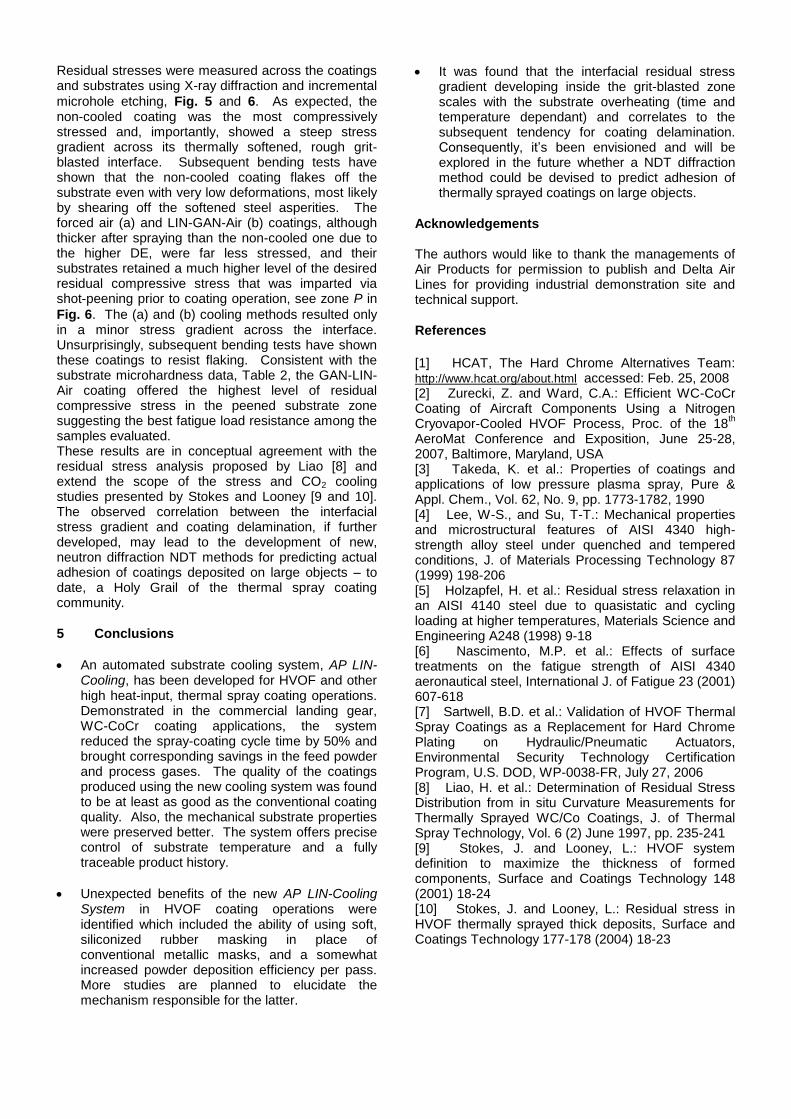
microhole etching, Fig. 5 and 6. As expected, the non-cooled coating was the most compressively stressed and, importantly, showed a steep stress gradient across its thermally softened, rough grit-blasted interface. Subsequent bending tests have shown that the non-cooled coating flakes off the substrate even with very low deformations, most likely by shearing off the softened steel asperities. The forced air (a) and LIN-GAN-Air (b) coatings, although thicker after spraying than the non-cooled one due to the higher DE, were far less stressed, and their substrates retained a much higher level of the desired residual compressive stress that was imparted via shot-peening prior to coating operation, see zone P in
Fig. 6. The (a) and (b) cooling methods resulted only in a minor stress gradient across the interface. Unsurprisingly, subsequent bending tests have shown these coatings to resist flaking. Consistent with the substrate microhardness data, Table 2, the GAN-LIN-Air coating offered the highest level of residual compressive stress in the peened substrate zone suggesting the best fatigue load resistance among the samples evaluated. These results are in conceptual agreement with the residual stress analysis proposed by Liao [8] and extend the scope of the stress and CO2 cooling studies presented by Stokes and Looney [9 and 10]. The observed correlation between the interfacial stress gradient and coating delamination, if further developed, may lead to the development of new, neutron diffraction NDT methods for predicting actual adhesion of coatings deposited on large objects – to date, a Holy Grail of the thermal spray coating community.
5 Conclusions
An automated substrate cooling system, AP LIN-Cooling, has been developed for HVOF and other high heat-input, thermal spray coating operations. Demonstrated in the commercial landing gear, WC-CoCr coating applications, the system reduced the spray-coating cycle time by 50% and brought corresponding savings in the feed powder and process gases. The quality of the coatings produced using the new cooling system was found to be at least as good as the conventional coating quality. Also, the mechanical substrate properties were preserved better. The system offers precise control of substrate temperature and a fully traceable product history.
Unexpected benefits of the new AP LIN-Cooling System in HVOF coating operations were identified which included the ability of using soft, siliconized rubber masking in place of conventional metallic masks, and a somewhat increased powder deposition efficiency per pass. More studies are planned to elucidate the mechanism responsible for the latter.
It was found that the interfacial residual stress gradient developing inside the grit-blasted zone scales with the substrate overheating (time and temperature dependant) and correlates to the subsequent tendency for coating delamination. Consequently, it’s been envisioned and will be explored in the future whether a NDT diffraction method could be devised to predict adhesion of thermally sprayed coatings on large objects.
Acknowledgements The authors would like to thank the managements of Air Products for permission to publish and Delta Air Lines for providing industrial demonstration site and technical support.
References
[1] HCAT, The Hard Chrome Alternatives Team: http://www.hcat.org/about.html accessed: Feb. 25, 2008 [2] Zurecki, Z. and Ward, C.A.: Efficient WC-CoCr Coating of Aircraft Components Using a Nitrogen Cryovapor-Cooled HVOF Process, Proc. of the 18
th
AeroMat Conference and Exposition, June 25-28, 2007, Baltimore, Maryland, USA [3] Takeda, K. et al.: Properties of coatings and applications of low pressure plasma spray, Pure & Appl. Chem., Vol. 62, No. 9, pp. 1773-1782, 1990 [4] Lee, W-S., and Su, T-T.: Mechanical properties and microstructural features of AISI 4340 high-strength alloy steel under quenched and tempered conditions, J. of Materials Processing Technology 87 (1999) 198-206 [5] Holzapfel, H. et al.: Residual stress relaxation in an AISI 4140 steel due to quasistatic and cycling loading at higher temperatures, Materials Science and Engineering A248 (1998) 9-18 [6] Nascimento, M.P. et al.: Effects of surface treatments on the fatigue strength of AISI 4340 aeronautical steel, International J. of Fatigue 23 (2001) 607-618 [7] Sartwell, B.D. et al.: Validation of HVOF Thermal Spray Coatings as a Replacement for Hard Chrome Plating on Hydraulic/Pneumatic Actuators, Environmental Security Technology Certification Program, U.S. DOD, WP-0038-FR, July 27, 2006 [8] Liao, H. et al.: Determination of Residual Stress Distribution from in situ Curvature Measurements for Thermally Sprayed WC/Co Coatings, J. of Thermal Spray Technology, Vol. 6 (2) June 1997, pp. 235-241 [9] Stokes, J. and Looney, L.: HVOF system definition to maximize the thickness of formed components, Surface and Coatings Technology 148 (2001) 18-24 [10] Stokes, J. and Looney, L.: Residual stress in HVOF thermally sprayed thick deposits, Surface and Coatings Technology 177-178 (2004) 18-23