improved coating properties and optimized substrate...
TRANSCRIPT

8th International Tribology Conference, 8. - 10. Oktober 2003., Belgrade, Serbia 3
IMPROVED COATING PROPERTIES AND OPTIMIZED SUBSTRATE DATA, ESSENTIAL CONDITIONS FOR HIGH
PERFORMANCE CUTTING TOOLS
K.–D. BOUZAKIS, I. MIRISIDIS, S. HADJIYIANNIS, G. SKORDARIS, N. MICHAILIDIS, Laboratory for Machine Tools and Manufacturing Engineering, Mechanical Engineering
Department, Aristoteles University of Thessaloniki, 54124 Thessaloniki, Greece
G. ERKENS, R. CREMER CemeCon GmbH, Adenauerstr. 20B1, D-52146 Würselen, Germany
S u m m a r y The fatigue and the wear behavior of coatings with various mechanical strength and thickness, on
cemented carbide substrates are investigated experimentally in milling and analytically using a Finite Elements Method (FEM) simulation. The hereby-required coatings and substrates mechanical properties are determined by means of FEM supported evaluation procedure of nanoindentation test results. The initiation and progress of the coating and tool wear, for all the investigated cases, were studied using scanning electron microscopy and energy dispersive X-ray spectroscopy.
Further investigations using a novel (Ti,Al)N based Supernitride PVD coating, with an AlN content close to the conductivity limit of 65-67mol-% AlN, were conducted and the results extracted are compared to the corresponding ones of an effective state of the art (Ti46Al54)N coating, thus demonstrating a superior performance of the Supernitride coating, especially at elevated cutting temperatures. The oxidation resistance growth, as well as the deterioration of the thermal conductivity though the increasing of the AlN content was taken into account to depict enhanced cutting performance of the examined supernitride coating.
Through the reconditioning of worn coated cutting tools by means of appropriate de-coating, micro-blasting and physical vapour deposition (PVD) recoating procedures, a production cost decreasing is intended. However, the cutting performance of recoated tools may be impaired compared to the corresponding one of new tools, due to the fact that during the reconditioning processes strength properties modifications in the substrates are induced, resulting in a potential wear behaviour deterioration. In this way, the cutting performance reliability and in general the tool cost management could be unfavourably affected. In the investigations described, the previously mentioned procedure based on nanoindentations and a finite elements method (FEM) supported evaluation of the corresponding measurement results is applied. This method enables the determination of related internal stress alterations at every stage of reconditioning procedures. The occurring surface stress modifications in cemented carbides inserts during reconditioning procedures might affect the tool cutting performance. Investigations in milling and gear hobbing showed that the inferiority of the tool wear behaviour when using reconditioning cemented carbides tools, could be drastically reduced. The methodology introduced, contributes to the achievement of this target, since it facilitates the accurate assessment of the reconditioning procedures effect on the tool mechanical properties.
Keywords: PVD coatings, coating thickness, tool reconditioning, micro-blasting, milling.

8th International Tribology Conference, 8. - 10. Oktober 2003., Belgrade, Serbia
4
1. INTRODUCTION The evolution of Physical Vapour Deposition (PVD)
technologies facilitated the development of enhanced cutting tool coating materials in order to improve their productivity in manufacturing processes [1,2]. Coatings, tool materials and tool geometries have a considerable importance due to the increasing requirements of modern and innovative production processes. Furthermore the reconditioning of worn coated cemented carbides tools through electro- chemical coating removal, micro-blasting and physical vapour deposition (PVD) recoating gains a wide industrial interest [3,4].
Figure 1 indicates potential magnitudes influencing the cutting performance of coated tools. In the present paper, the effects of these parameters, i.e. the coating strength properties, thickness and material composition as well as the reconditioning of cutting tools and the micro-blasting, on the wear behavior will be demonstrated.
Besides the parameters listed in the previous figure, further numerous ones affect the cutting performance as shown indicatively in recent publications [5-14]. PVD coatings as well as the Supernitride coating (especially at elevated cutting temperatures) on cemented carbides inserts improve the cutting tool performance. Moreover the inferiority of the tool wear behaviour in milling and gear hobbing when using reconditioning cemented carbides tools, could be drastically reduced.
Figure 1: Parameters affecting the coated tool cutting performance.
2. COATING STRENGTH PROPERTIES
In general, coating microstructure varies with increasing coating thickness. The coating growth mechanisms lead to increased superficial grains size, whereas on an intermediate plane, parallel to the
substrate surface, the corresponding grain size is smaller [15,16,17], as schematically presented in figure 2. This fact is related to the mobility of the adatoms during the film growth, because the deposited coating becomes progressively insulating. In this way it acts as a barrier to the plasma flux and deteriorates the energetic particle bombardment of the film surfaces. [18,19].
Figure 2: Coating microstructures and occurring grain sizes at various coating thickness.
Characteristic probability distributions of PVD coated inserts superficial hardness with different film thickness and common all other technological data are presented in figure 3. Inserts with the same film thickness were coated together, in separated PVD processes, using the same High Ionization Sputtering (HIS), however according to the desired thickness, with different long deposition times. In both coating thickness cases the distributions of the occurring hardness probabilities are similar in magnitude and shape. The reduction of the maximum superficial hardness (Nominal Hardness NH) values at the larger coating thickness occurs, due mainly to the coarser superficial coating microstructure. Hence it is expected that the mechanical strength properties of thin coatings are enhanced in comparison to corresponding ones of thicker films.
The introduced continuous FEM simulation model of the nanohardness procedure presented in [20,21] was appropriately modified in order to extract the stress strain laws of the superficial regions of each investigated coating (see figure 4). In the first step of this procedure, with already determined substrate properties, the “SSCUBONI” algorithm is applied to calculate the mechanical properties of the superficial region of the thinnest of the investigated coatings of 2 µm assuming that these are constant all over the coating thickness. Considering the extracted properties, the “SSCUBONI” algorithm was further applied in order to determine the stress strain curves of the superficial region of the next investigated coating with 4 µm film thickness. Hereupon the coating is considered to consist of two layers each one with film thickness of 2 µm and

8th International Tribology Conference, 8. - 10. Oktober 2003., Belgrade, Serbia 5
own strength properties. This procedure was repeated for all investigated coatings the thickness of which was increased each time for 2 µm. In this way the individual “layer” strength properties of thick coatings can be accurately determined.
Figure 3: Superficial hardness distribution probability at different coating thicknesses.
Figure 4: Coatings stress strain curves determination, by means of the FEM simulation of the nanoindentation procedure and indenter tip form deviations description.
The equivalent stress-strain relation for the coatings was determined from the nanoindentation results. The nanohardness measurement is a precise indentation method to register continuously the course of the applied force versus the occurring penetration depth.
With the aid of the nanoindentation procedure the elastoplastic film laws of the 200 coated cutting inserts were determined through the mentioned FEM supported evaluation method [20,21,22] and properly recorded. The extracted yield and maximum strength and yield strain as a function of the film hardness and indentation depth for the deposited coatings having various thicknesses are shown in figure 5a and 5b. The magnitudes of the parameters th and b in figure illustrated, which describe the indenter tip form deviations from the ideal geometry, are determined using the methodology in [21] introduced. According to these results the film hardness and the coating strength depend on each other. Therefore further investigations in milling were carried out to show how the improved strength affects the cutting behaviour.
Figure 5: The von Mises equivalent yield and maximum stress as well as the equivalent yield strain versus the coating hardness of the investigated coatings.
In the FEM simulations of the coated inserts, in next sections described, the film strength properties versus the film thickness are taken into account. In order to determine these properties the behavior of the coating

8th International Tribology Conference, 8. - 10. Oktober 2003., Belgrade, Serbia
6
hardness as a function of the coating thickness t is considered, as illustrated in figure 6. The coating hardness distribution at a depth di within the surface, is supposed to have the same shape and the corresponding distribution in a coating having thickness ti (≈ t-di). The superficial hardness distributions and furthermore the corresponding film stress-strain laws at various coating thicknesses were determined experimentally, using each time one of the mentioned cutting insert groups, consisting of 40 parts with approximately constant coating thickness. Moreover the stress strain laws of the investigated (Ti46Al54)N films according to measured indentation depths and to dependencies shown in figure 5 can be defined as demonstrated in the figure.
Figure 6: Coating hardness and stress strain curves determination at a depth di by means of the superficial hardness, its occurrence probability p and its dependence on mechanical properties.
3. EFFECT OF COATINGS HARDNESS AND THICKNESS ON THEIR MIL-LING PERFORMANCE
The tool cutting edge wear condition at early tool wear stages, i.e. up to 4x10⁴ cuts, was monitored by means of optical and Scanning Electron Microscopy (SEM) investigations, as well as Energy Dispersive X-ray (EDX) spectroscopy. The experiments were performed using a 3-axis numerically controlled milling centre. A prescribed number of successive cuts was set before every inspection of the cutting insert wear status.
The cutting edge wear status for coatings having a thickness of 10 µm and varying hardness is illustrated in figure 7. It is evident that in all cases up to 5x10³ cuts, no coating fracture, revealing the substrate occurred. The coated insert with the medium hardness (1750 HV15mN) shows an intermediate milling performance in comparison to the other two cases investigated. The coated insert with the increased hardness (2400 HV15mN) possesses a slightly improved milling performance as compared to all others. It is obviously shown that in the case of thick coatings the influence of the hardness is insignificant.
Figure 7: Flank wear development in milling with cemented carbides inserts, coated with various thick but equal hard films.
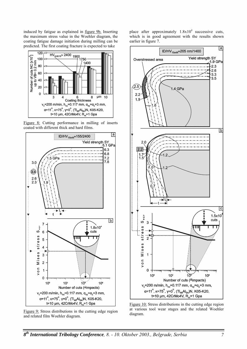
The obtained number of cuts up to a flank wear of 0.2 mm for all coating thickness and hardness cases are illustrated in figure 8. The strength and the hardness affect significantly the cutting performance mainly for thin coatings. For thicker coatings the effect is less significant. Their cutting performance is almost independent of the coating hardness.
In order to explain wear behaviour of the coated inserts a FEM model [23,24,25] of the milling process was used. Taking into account how the coating material strength depends on its thickness, the stress distribution in the coating during the material removal can be studied.
The following investigations deal with the thick PVD films (≈10 µm). Corresponding results for thinner 4 µm thick coatings have been performed previously [23]. The stress distribution in the thick 10 µm coating having a hardness of 2400 HV15mN is shown in figure 9a. The maximum stress on the coating surface is 3.4 GPa and it is lower than the yield strength of the coating surface zone (5.4 GPa). The coating fracture initiation is
8th International Tribology Conference, 8. - 10. Oktober 2003., Belgrade, Serbia 7
induced by fatigue as explained in figure 9b. Inserting the maximum stress value in the Woehler diagram, the coating fatigue damage initiation during milling can be predicted. The first coating fracture is expected to take
Figure 8: Cutting performance in milling of inserts coated with different thick and hard films.
Figure 9: Stress distributions in the cutting edge region and related film Woehler diagram.
place after approximately 1.8x10⁴ successive cuts, which is in good agreement with the results shown earlier in figure 7.
Figure 10: Stress distributions in the cutting edge region at various tool wear stages and the related Woehler diagram.

8th International Tribology Conference, 8. - 10. Oktober 2003., Belgrade, Serbia
8
The stress distribution in the 10 µm thick coating having hardness of 1400 HV15mN is shown in figure 10a. In this case the maximum stress (2.5 GPa, see figure 10a) is above the coating superficial yield strength, which is 1.9 GPa. An overstressed area near the edge rounding occurs. It leads to coating fracture in that region only after a small number of cuts. The corresponding Woehler diagram for this coating material is shown in figure 10c. It indicates clearly that after ca. 200 cuts the coating fracture due to fatigue might start. Thus the less hard coating is slightly and locally damaged and the substrate is not revealed. Therefore the substrate could not longer be scanned after 5x10³ number of cuts, as already shown in the upper right SEM micrograph in figure 7. The progressive coating damage modifies the effective cutting edge geometry, as demonstrated in figure 10b. The load in critical areas becomes then lower (2.2 GPa) due to the increased cutting edge radius as found also in [24]. This progressive damage of the cutting edge reveals inner coating layers, which have higher strength. Thus the coating fatigue failure risk is decreasing, the abrasion resistance is improved and the wear is reduced. Due to this fact and in spite of the low hardness of 1400 HV15mN the coating stands without fracture approximately 1.5x10⁴ cuts, according to the Woehler diagram, in figure 10c illustrated. These results are also in accordance to the SEM observations of the cutting edge as shown earlier in figure 7, whereas after 2x10⁴ cuts a substrate reveal was monitored. 4. PERFORMANCE OF HIGH ALUMI-
NUM CONTAINING (TI,AL)N BASED SUPERNITRIDE COATINGS IN CUTTING APPLICATIONS
Coatings, tool materials and tool geometries have a
considerable importance due to the increasing requirements of modern and innovative production processes. In terms of dry machining, hard machining, high speed cutting (HSC) and high performance cutting(HPC), new concepts for high performance coatings are needed.
One of the most effective state of the art coatings is the metastable solid solution phase (Ti,Al)N in cubic B1 structure, offering superior oxidation resistance and hardness [2,26].
With increasing aluminum content the oxidation resistance of (Ti,Al)N coatings increases, however a barrier is set to PVD process technology by the deposition of insulating films at a film composition of approx. 65-67mol-% AlN. The High Ionization Sputtering (H.I.S.) process technology makes an asymptotic convergence towards this limit possible [27]. The films become insulating whereas the sputter sources remain conductive. At this limit the (Ti,Al)N Supernitrides of the first generation can be deposited, whereas the PVD-target will remain conductive.
In figure 11 the plasma density measurement results in a region very close to the substrate surface, by means of an energy selective mass spectrometer is demonstrated. The Ti+-ion concentration is registered during the deposition of a (Ti,Al)N coating by means of conventional DC sputtering, as well as during the H.I.S. and the novel H.I.P. PVD process. For the same basic PVD conditions, the new H.I.P. process delivers much higher ionization close to the substrate in comparison to the conventional DC-process and the H.I.S. one. The high-energetic slope of the Ti+-ions contributes significantly to the formation of ultra-dense plasmas in front of the tool to be coated and ensures an enhanced quality for nano-crystalline and nano-structured coatings together with nano-composites. In addition, it optimizes deposition rates.
Figure 11: Energy distribution of Ti+-ions using conventional DC, H.I.S. and H.I.P. PVD technologies.
Figure 12a illustrates the experimentally determined
non-equilibrium phase diagram of the system TiN-AlN [28]. Although TiN and AlN show no solubility under equilibrium conditions, a wide solubility of these two phases can be achieved under the condition of non-equilibrium in PVD. This target is fulfilled through process managing far away from equilibrium, so that a metastable phase, in a local, kinetically determined energy minimum is formed. To overcome the situation just to converge towards the conductivity limit of approx. 65-67mol-% AlN in the case one variant of (Ti,Al)N based Supernitrides, a novel plasma enhance sputtering process has been developed, which is capable of depositing conductive and insulating coatings in virtually any stoichiometry [27]. The High Ionization Pulsing (H.I.P.) process technology maintains the glow discharge in front of the sputter sources and makes it possible to deposite films with an Al/Ti ratio up to 5. The realization of extremely dense plasmas becomes possible through the application of pulsed plasmas and a new arrangement in the vacuum chamber, that increases the potential difference between the pulse electrodes and thus the ion energy, contributing herewith to the guidance of dense plasmas specifically to the substrate. This plasma enhancement is necessary to shift the

8th International Tribology Conference, 8. - 10. Oktober 2003., Belgrade, Serbia 9
transition from the cubic B1 structure to the hexagonal Wurzite one, towards higher AlN content and thus the high hardness of the well known, commercially available coatings with Al/Ti ratios of about 1 can be preserved. Figure 12b illustrates the fracture structure of a characteristic (Ti,Al)N based Supernitride variant, the SNTR with an AlN content close to the conductivity barrier (≈67 mol-%) and a state of the art (Ti46Al54)N wear protective film [2,26]. It is evident that the microstructure of the investigated (Ti,Al)N based Supernitride is distinguished by a more fine grained, nano-crystalline structure in comparison to the conventional (Ti46Al54)N one. A further advantage of the Supernitride films is that their morphology and texture can be varied within a wide range, best adapted to the demands of modern applications, due to the possibilities offered by modern PVD process technologies like High Ionization Sputterung (H.I.S.) and High Ionization Pulsing (H.I.P.) [27].
Figure 12: Phase diagram of the metastable system TiN-AlN and microstructure of a Ti46Al54N coating and a nano-structured supernitride (SNTR) one. 4.1 Properties of the investigated Supernitride
coatings The nanohardness diagrams of the two above
mentioned coatings are presented in the upper part of figure 13.
The indentation depth versus the indentation force courses demonstrate the higher SNTR-coating hardness in comparison to the (Ti46Al54)N one. By means of a continuous simulation of the nanoindentation [22], the coatings’ stress-strain curves were extracted and are shown in the bottom part of figure 13. Concluding these
results, it can be stated that although the SNTR coating possesses a slightly diminished elasticity modulus compared with the (Ti46Al54)N film, it has, on the other hand, due to its higher hardness, an increased equivalent yield and maximum strength in comparison to the (Ti46Al54)N film.
Figure 13: Nanohardness diagrams and the extracted stress strain curves of the examined coatings.
In order to investigate the coatings fatigue behaviours, the impact test was applied (see figure 14a) [29]. During the impact test an oscillating carbide ball penetrated periodically under a desired maximum load level into the coating. Impacts tests were performed at various impact forces and durations (see figure 14b). SEM micrographs are shown in figure 14c, indicating that the coating fatigue fracture initiation takes place after 106 impacts at an impact load between 39 and 44 daN. With the aid of a FEM simulation of the contact between the ball indenter and the coated insert have during the impact test, the critical stresses leading to the film damage initiation can be determined and Smith and Woehler diagrams of the tested coating materials are elaborated (see figure 14d) [30]. These diagrams are taken into account in coating fatigue fracture considerations in milling, as described in the following section.
The coating mechanical properties besides chemical stability, oxidation resistance and thermal conductivity significantly affect wear behaviour in cutting tools applications. While all these parameters can contribute to a tool performance enhancement at elevated cutting temperatures, at low and moderate ones, the coating mechanical

8th International Tribology Conference, 8. - 10. Oktober 2003., Belgrade, Serbia
10
properties and especially fatigue behaviour influence mainly their wear evolution. Therefore in the following sections the wear behaviour of the applied coatings will be at first introduced at moderate cutting temperatures and furthermore at elevated ones.
Figure 14: Impact test results concerning the fatigue behaviour of the SNTR coating.
4.2 Wear behaviour of the supernitride SNTR coating, compared to (Ti46Al54)N at moderate cutting speeds
In order to check the cutting performance of the
applied coatings milling experiments with a hardened steel of 1 GPa maximum tensile strength, as workpiece material, were performed using a CNC machining centre. Considering already published results [22], the cutting speed, taking into account the mentioned workpiece material properties, was held at a medium level (200 m/min), in order to avoid coating failures due to thermo-oxidation occurring at elevated cutting temperatures, especially on the rake face close to the tip of the cutting edge. The necessary predetermined number of successive cuts was accomplished by following prescribed circular paths in continuous up cut kinematics. Dry airflow was used as a coolant and chip remover.
Figure 15: Flank wear development versus the number of cuts for the examined coatings and SEM photographs of the examined coatings at various wear stages.

8th International Tribology Conference, 8. - 10. Oktober 2003., Belgrade, Serbia 11
The flank wear development versus the accumulated number of cuts of cutting inserts coated with the (Ti46Al54)N coating and the Supernitride SNTR one are shown in the upper part of figure 15. The related experimental data are valid for all the following figures, demonstrating the wear behaviour of the applied coatings. The cemented carbide inserts, coated with the Supernitride SNTR, exhibited a better cutting performance reaching a tool life of approximately 82x103 cuts at a flank wear width of 0.2 mm, while the first coating fracture appeared almost after ca. 8x10³ cuts. On the other hand, the coated inserts with (Ti46Al54)N reached only 55x103 cuts up to the same maximum flank wear width, whereas the first coating fracture occurred earlier, after about 3.5x10³ cuts.
Figure 16: SEM simulation results and first coating fracture expectations, considering the applied coatings Woehler diagrams.
The cutting wedges wear status of the examined
coatings at various cutting stages are demonstrated in the bottom part of figure 15. As it can be observed in the SEM micrographs, the first coating damage of the (Ti46Al54)N film took place, as already mentioned, at a lower number of cuts in comparison to the Supernitride SNTR coating. In both coating cases, the first coating fracture appeared on the tool flank near the tip of the cutting edge and the further wear propagation occurs on the flank and on the rake simultaneously.
In order to explain these results, tool mechanical stresses FEM-supported calculations by means of the method introduced in [31] were conducted. The chip contact length (ccl) was registered with the aid of micrographs, indicating the chip tool contact area
width during turning at the same as in milling cutting conditions. The FEM calculations results for both applied coatings are presented in figure 16. In both cases, the maximum von Mises equivalent stress developed appeared on the cutting edge roundness, close to the flank. In the case of the Supernitride SNTR coating, the maximum stress was higher compared with the (Ti46Al54)N coating, mainly due to the deteriorated contact width (ccl) between the flowing chip and the tool rake, caused by the more restricted thermal conductivity of the SNTR coating. This effect is further analyzed in the next section.
Inserting the determined stresses into the coatings Woehler diagrams, by means of the experimental techniques found out, in [29,30] described, the coatings fatigue damage can be predicted. The first coating fracture was expected to take place after approximately 3,5x10³ and 8x10³ cuts for the (Ti46Al54)N and the Supernitride SNTR coatings, respectively. These results were in good agreement with the experimental ones shown in figure 15, although the equivalent stresses, occurring during cutting with SNTR coated inserts were higher in comparison to the corresponding ones in milling using (Ti46Al54)N films. The higher maximum equivalent strength of the SNTR coating, (see figure 13), lead mainly to higher fatigue safe equivalent stresses up to restricted number of cuts and herewith to longer tool cutting time up to the first coating fracture. The further SNTR coating destruction was less intensive compared with the (Ti46Al54)N film case. Thus, the improved mechanical properties of the Supernitride coatings contributed to a cutting performance enhancement at low and moderate cutting speeds i.e. process temperatures. 4.3 Wear behaviour of the supernitride
coating SNTR compared to the (Ti46Al54)N film at high cutting speeds
Besides the improved mechanical properties,
further significant coating parameters for their effective application on cutting tools especially at elevated cutting temperatures are film oxidation resistance and thermal conductivity.
Supernitride coatings are distinguished among others by high oxidation resistance and chemical stability. Micro-probe analyses of oxidized (Ti,Al)N based Supernitride coatings proved that with increasing AlN content, a dense Supernitride oxide layer is generated much faster, preventing in this way a further coating bulk oxidation.
In order to characterize the thermal conduc-tivities of the examined coatings, measurements of the chip contact length (ccl) in both coating cases were carried out at various cutting speeds in turning [32]. The chip contact length (ccl) decreased versus

8th International Tribology Conference, 8. - 10. Oktober 2003., Belgrade, Serbia
12
the applied cutting speed in all investigated cases, as illustrated in figure 17a.
Figure 17: Chip contact length, chip formation and cutting force components in turning with uncoated and with various PVD films coated tools.
The cutting thermal energy occurring due to the
material deformation and removal, at early cutting stages, when the coatings are undamaged and operating ideally as thermal barriers and friction reducers was transferred mainly into the workpiece material and removed by the formed chips. Moreover, the high temperature gradient between the chip face being in contact with the tool rake and of the corresponding opposite one lead to a strong bending and to helical chip formation. A deteri-
orated coating thermal conductivity supports these phenomena. In this way, the chip-tool contact length progressively diminished and the helical chip formation became more intensive as the chip geometries in turning with uncoated as well as with (Ti46Al54)N and SNTR coated inserts shown in figure 17b, clearly indicate. In the case of the Supernitride SNTR coating, the obtained chip contact length values at all applied cutting speeds were lower than the corresponding ones, when a (Ti46Al54)N coating or uncoated tools was used. Hence the part of the thermal cutting energy flowing into the workpiece material, induced an additional workpiece temperature grown and herewith a material strength deterioration, which resulted in corresponding cutting force components decreases, as illustrated in figure 17c. Taking into account these results, a deterioration of the thermal conductivity through the increasing of the AlN content can be concluded and herewith enhanced thermal and wear protection are expected. The wear superiority of the Supernitride SNTR coating at high cutting speeds can be observed in figure 18. The diminishing of the achieved number of cuts as the cutting speed increases is evident in both examined cases. Moreover it is obvious that the nano-structure and the increased AlN content act more positively on the behaviour of the Supernitride SNTR coating at higher cutting speeds. The increase (%) of the successive number of cuts for the Supernitride coating, in comparison to the (Ti46Al54)N coating is also illustrated. At a cutting speed of 600 m/min this percentage increase of ca. 300 %, is almost twice higher in comparison to the corresponding growth at a cutting speed of 200 m/min.
Figure 18: Cutting performance of the applied coatings at various cutting speeds.

8th International Tribology Conference, 8. - 10. Oktober 2003., Belgrade, Serbia 13
5. INTERNAL STRESS ALTERATIONS IN PVD FILMS AFTER RECOATING PROCEDURES AND THEIR EFFECT ON THE CUTTING PERFORMANCE
The potential of reconditioning of worn coated cemented carbides tools through electro- chemical coating removal, micro-blasting and physical vapour deposition (PVD) recoating gains a wide industrial interest. However, the effect of all these sequential procedures on the mechanical properties and on the cutting performance of recoated cemented carbides tools has to be taken into account [24,33].
The cutting performance of recoated inserts after successive reconditioning procedures has been investigated in milling and in gear hobbing through Scanning Electron Microscopy (SEM) and optical microscopy observations and Energy Dispersive X-ray (EDX) spectroscopy microanalyses as well. In this way, the effect of the inserts strength properties deterioration on cutting edge micro-chippings formation and on the subsequent wear development was possible to be accurately encountered.
Figure 19: The conducted investigations methodology.
The methodology of the conducted experimental procedures is illustrated in figure 19. In all the investigations, K05-K20 and K35 cemented carbides inserts were applied in successive reconditioning steps. Every investigation step includes three sub-procedures, the micro-blasting on the cemented carbides inserts top and side surfaces, the PVD-coating and the electrochemical de-coating as in figure indicated. These procedures were repeated five times. The PVD film was deposited through High Ionization Sputtering (HIS) by means of a CC800® /9 coating system only on the each time micro-blasted inserts surfaces. At the end of a sub-procedure in every investigation’s step, a cutting inserts
portion was held, in order to conduct the nano-indentations previous mentioned and the wear investiga-tions in milling. The de-coating process was conducted electrochemically for a properly time, until the substrate of the coated upper surface of the cemented carbides inserts was revealed.
Figure 20: Modifications of the maximum nano-indentation depth on cemented carbides inserts before and after micro-blasting procedures in the individual investigation steps.
5.1 Substrate surface mechanical properties after successive reconditionings Micro-blasting is currently used on cemented
carbides substrates as a common method to reduce high roughness peaks, to remove binding material (Co) from the surfaces to be coated and to induce superficial compressive stresses [24,33,34]. In this way internal stress alterations result, which can be determined adequately by means of nanoindentations [20,21, 22,35,36]. The maximum indentation depths on the de-coated substrates registered and their alterations after micro-blasting procedures in the successive investi-gation steps are demonstrated in figure 20. The thermal treatments during the PVD recoating procedures in the successive investigation steps, significantly diminish the substrate hardness as the increasing maximum indentation depths show, due to isothermal stress

8th International Tribology Conference, 8. - 10. Oktober 2003., Belgrade, Serbia
14
relaxation owing to thermally activated plastic flow (dislocation climb, grain boundary and volume diffusion) [19]. On the other hand in both examined cemented carbides materials, the micro-blasting essentially contributes to the decrease of the maximum penetration depth to the initial insert values. Herein although the hardness increases after the first micro-blasting, in both cutting plate cases, are not significant compared to the occurring ones in the further investigation steps, the compressive stresses induced are not negligible, as the results in the following sections described, show. The yield strength reduction of the cemented carbides inserts, due to the previous mentioned isothermal stress relaxation during the sequential PVD recoating procedures can’t be fully removed through micro-blasting, as in figure 21 demonstrated. The equivalent yield strength of the cemented carbides inserts decreases successively versus the investigation steps, whereas the micro-blasting procedure contributes to the superficial compressive stresses growth and enhances the yield strength properties, which possesses a descending tendency versus the insert reconditioning times.
Figure 21: Equivalent yield strength alterations of cemented carbides inserts before and after micro-blasting procedures in the individual investigation steps.
Figure 22: Equivalent stress distributions and principal stresses at the reference point rp in a cemented carbide insert k35 before and after a micro-blasting procedure.
5.2 Substrate internal stress alterations due to de-coating and micro-blasting
During the nanoindentation, the cemented carbides
insert region under the penetrating indenter is progressively deformed plastically. In the case of an untreated cemented carbides insert K35, at a reference point RP within the insert material, the transition into the plastically deformed region takes place at the

8th International Tribology Conference, 8. - 10. Oktober 2003., Belgrade, Serbia 15
indentation force and depth indicated in figure 22a, where the occurring von Mises stresses distribution can be observed. In the case of the same, however micro-blasted insert, this process is activated at a higher indentation load and depth, because the yield strength now is increased (see figure 22b). The corresponding principal stresses in figure 22c inserted, indicate that due to the micro-blasting procedure conducted, the plastic deformation of the cemented carbides material starts at a higher compressive stress σ3 level compared to that one of the untreated insert. The compressive principal stress σ3, for the material transition into the plastic deformation required, is increased from 2.5 up to 3.1 GPa, in absolute values after the micro-blasting procedure, whereas the principal stresses σ1 and σ2 remain unaffected. Thus it has to be pointed out that the von Mises stresses Seqv difference (0.7 GPa) is equal to the corresponding one of the yield strengths SY. This difference obviously is due to the internal stress modifications induced by the micro-blasting procedure.
The induced compressive stresses alterations in the de-coated cemented carbides inserts after the successive micro-blasting procedures are shown in figure 23. The occurring increase of the compressive stresses is equal to the yield stress differences. According to these results and as already described, the micro-blasting procedure contributes initially to a significant increase of the compressive stresses of approximately 1.2 GPa for the K05-K20 and of 0.7 GPa for the K35 inserts, respectively. Moreover, the surface zone compressive stress growth, which can be achieved through micro-blasting, increases versus the investigation steps, for ca. 1.7 and 0.9 GPa for the cutting plates K05-K20 and K35 correspondingly after five recoating cycles. A consequence of this may be a potential cutting edge micro-chipping initiation after a coating damage due to cutting loads, because the existing deteriorated mechanical properties before the micro-blasting procedure still remain active within the insert material. This assumption was ascertained by wear investigations in milling, which are presented. 5.3 Wear development in milling and gear hobbing with recoated cutting tools
In order to investigate the cutting performance of reconditioned cutting inserts, milling experiments were carried out. These investigations were performed using a 3-axis numerically controlled milling centre. A prescribed number of successive cuts were set before every inspection of the cutting insert wear status. The tool wear condition was monitored by means of optical and SEM observations. The obtained results concerning the flank wear development versus the number of cuts are illustrated in figure 24a. As it can be observed, the same initial wear development practically occurs with the one time and five times recoated cutting inserts. However, as the related curves indicate, the inserts for the first time coated, possess a better cutting performance, reaching an increased number of cuts up
to a flank wear width of approximately 0.2 mm, compared to the corresponding one with a five times recoated cutting insert.
Figure 23: The effect of micro-blasting on internal stress modifications of HM insert surfaces in the individual investigation steps.
The cutting edge condition of cemented carbides inserts K05-K20 applied, after various numbers of cuts are demonstrated in figure 24b. Cutting edge chippings and corner fracture occur earlier in the five times reconditioned cutting insert, due to the mechanical properties deterioration described, after the sequential reconditioning procedures. Herein the superficial properties enhancement due to micro-blasting is not capable to ensure a sufficient cutting edge stiffness, comparable to that one of the first time coated inserts, after the first coating damage. The first coating fracture occurs in the transient cutting edge area, from the tool rake to the flank [32,37]. Hereupon, due to the elevated substrate thermal loads after the coating fracture and the substrate reveal, the restricted substrate properties lead to an insert cutting edge corner damage which proceeds faster in comparison to the case when first time coated inserts are used.

8th International Tribology Conference, 8. - 10. Oktober 2003., Belgrade, Serbia
16
Figure 24: Flank wear development versus the number of cuts of cemented carbides inserts after various coating times.
Figure 25: Cutting performances of reconditioned tools of various cemented carbides qualities and at various flank wears in gear hobbing and milling.
Further investigations regarding the effect of re-conditioning cycles on the wear behaviour of industrial used hobs were performed [4]. The experiments were conducted with various coated cemented carbides tools in hobbing of gears of planet gearboxes. The tool lives
after five reconditioning cycles achieved, are compared to the corresponding ones obtained when tools, coated for the first time, are applied as shown in figure 25. This figure exhibits also related results in milling operations with various cutting cemented carbides inserts qualities. According to these results, the reconditioning procedures might lead to a reduction of the tool performances. However it should be pointed out that these reductions are negligible or can be fully avoided if as tool reconditioning criterion, a flank wear of approximately 0.1mm is considered, ie. if the tool is not used for a long period after the first coating damage. After the coating fracture, the inferior mechanical properties of reconditioned cemented carbides materials, under the few micrometers thick surface zones with enhanced mechanical properties, through micro-blasting achieved, lead to cutting edge micro-chippings and to a faster flank wear development. Herein the application of sub-micron cemented carbides tool materials containing a higher Co-content such as of K35 are less affected in the successive reconditioning cycles, according to the results in the present paper described.
6. CONCLUSIONS In the present paper PVD (Ti46Al54)N coated
cemented carbide inserts with various thickness and hardness were investigated and the extracted results indicated that the mechanical properties and the hardness significantly affect the cutting performance, especially in the case of the thinner coatings. In the case of thick coatings (8 up to 10 µm) the effect of the strength and hardness becomes less significant and wear depends mainly on the thickness of the coating itself.
Furthermore, the cutting performance of a Supernitride coating variant with an AlN content of ≈ 67 mol-% was compared to an effective state of the art (Ti46Al54)N film. The obtained wear performance at moderate cutting speeds were affected mainly by the coating mechanical properties. Moreover the oxidation resistance growth, as well as the deterioration of the thermal conductivity through the increasing of the AlN content, was taken into account in order to predict the enhanced cutting performance of the examined Supernitride coating SNTR in comparison to the (Ti46Al54)N coating, at high cutting speeds and thus elevated temperatures.
The successive reconditioning of worn coated cutting tools through complete electrochemical de-coating, micro-blasting and PVD recoating procedures deterio-rates the substrate mechanical properties and in general the wear behaviour as well. Through micro-blasting of cemented carbide inserts the mechanical properties are sufficiently improved. In order to avoid an inferior cutting performance of recoated tools in milling and in gear-hobbing, compared to the corresponding one of first-time coated tools, a law flank wear, approximately of 0.1mm, as a tool reconditioning criterion has to be considered. Moreover cemented carbides materials with higher Co-contents are recommended.

8th International Tribology Conference, 8. - 10. Oktober 2003., Belgrade, Serbia 17
7. REFERENCES 1. Rointan.F. Bunshah, Handbook of Hard Coatings, Noyes
Publications / William Andrew Puplishing, LLC, Norwich, New York, U.S.A, (.2001).
2. F. Klocke, T. Krieg, Coated Tools for Metal Cutting – Features and Applications, Annals of the CIRP, 42/2 (1999) 515-525.
3. F. Klocke, O. Hurasky-Schönwerth, M. Kleinjans, K.-D. Bouzakis, N. Michailidis, G. Skordaris, “Studies on changes in wear mechanisms of recoated cemented carbide hobs”, Proceedings of the 3rd international “THE” Coatings in Manufa-cturing Engineering conference, ZITI Publication-Thessaloniki-Greece, 2002, 101-110.
4. M. Kleinjans, Einfluss der Randzoneneigen-schaften auf den Verschleiβ von beschichteten Hartmetallwäl-zfräsern, Dissertation, RWTH Aachen, 2003.
5. K.-D. Bouzakis, N. Michailidis, S. Hadjiyiannis, E. Pavlidou, G. Erkens, Surface and Coating Techno-logies, 146-147 (2001) 436-442.
6. K.-D. Bouzakis, N. Michailidis, N. Vidakis, K. Efstathiou, T. Leyendecker, G. Erkens, R. Wenke, H. -G. Fuss, Surface and Coatings Technology, 133-134 (2000) 501-507.
7. K.-D. Bouzakis, N. Michailidis, N. Vidakis, K. Efstathiou, Wear, 248 (2001) 29-37.
8. K.-D. Bouzakis, N. Michailidis, N. Vidakis, K. Efstathiou, S. Kompogiannis, G. Erkens, Annals of the CIRP Vol. 49/1/2000 (2000), pp: 65-68.
9. G. Erkens, R. Cremer, T. Hamoudi, K.-D. Bouzakis, J. Mirisidis, S. Hadjiyiannis, G. Skordaris, A. Asimakopoulos, S. Kompogiannis, J. Anastopoulos, K. Efstathiou, Annals of the CIRP Vol. 52/1/2003 (2003), pp: 65-68.
10. K.-D. Bouzakis, S. Kompogiannis, A. Antoniadis, N. Vidakis, ASME J.Manuf.Sci.Eng.124 (2002)1 –10.
11. K.-D. Bouzakis, N. Michailidis, J. Anastopoulos, S. Kompogiannis, G. Erkens, P.J. Rudnik, Surface and Coatings Technology, 153 (2002) 148-154.
12. F. Klocke, T. Krieg, K. Gerschwiler, R. Fritsch, V. Zinkann, M. Pohls, G. Eisenblaetter, Annals of the CIRP, 47/1 (1998) 65-68.
13. Η. K. Toenshoff, B. Karpuschewski, A. Mohlfeld, T. Leyendecker, H. G. Fuss, G. Erkens, R. Wenke, Surface and Coatings Technology, 108-109, (1998) 535-542.
14. H. K. Toenshoff, A. Mohlfeld, International Journal of Machine Tools and Manufacture, 38 (1998) 469-476.
15. R. Messier, A. P. Giri, R. A. Roy, J. Vac. Sci. Technol. A, 2:500 (1984).
16. R. Messier, J. Vac. Sci. Technol. A, 4:490 (1986). 17. R. Messier, J. E. Yehoda, J. Appl. Phys., 58:3739 (1985). 18. J. Musil, S. Kadlec, V. Valvoda, R. Kuzel, R. Cerny,
Surface and Coatings Technology, vol. 43/44:259 (1990).
19. E. Kay, F. Parmigiani, W. Parrish, J. Vac. Sci. Technol. A, 6:3074 (1988).
20. K.-D. Bouzakis, N. Michailidis, G. Erkens, Surface and Coatings Technology, vol. 142-144 (2001) 102-109.
21. K.–D. Bouzakis, N. Michailidis, S. Hadjiyiannis, G. Skordaris, G. Erkens, Zeitschrift für Metallkunde, 93 (2002) 862-869
22. K.–D. Bouzakis, N. Michailidis, S. Hadjiyiannis, G. Skordaris, G. Erkens, Material Characterization, vol. 49-2 (2003) 149-156.
23. K.-D. Bouzakis, S. Hadjiyiannis, G. Skordaris, J. Anastopoulos, J. Mirisidis, N. Michailidis, K. Efstathiou, O. Knotek, G. Erkens, R. Cremer, S. Rambadt, I. Wirth, Surface and Coatings Technology, vol. 174-175 (2003) 393-401.
24. K.-D. Bouzakis, N. Michailidis, S. Hadjiyiannis, K. Efstathiou, E. Pavlidou, G. Erkens, S. Rambadt, I. Wirth, Surface and Coatings Technology, vol. 146-147 (2001) 443-450.
25. SWANSON Analysis System, INC., ANSYS user manuals, Vol.1 Theory, Vol.2 Procedures, Vol.3 Elements, Vol.4 Commands, (1995).
26. R. Bunshah, 2001, Handbook of hard coatings, Noyes Publications / William Andrew Publishing, N. York.
27. G. Erkens, R. Cremer, T. Hamoudi, S. Rambadt, I. Wirth, K.-D. Bouzakis, “About the development of novel high performance coatings for HPC applications”, Proceedings of the 4th International Conference on Metal Cutting and High Speed Machining, Darmstadt-Germany, 2003.
28. R. Cremer, M. Witthaut, D. Neuschütz, Value-Addition Metallurgy, The Minerals, Metals & Materials Society (1998) 249.
29. K.–D. Bouzakis, N. Michailidis, A. Lontos, A. Siganos, S. Hadjiyiannis, G. Giannopoulos, G. Maliaris, G. Erkens, Zeitschrift fuer Metallkunde, 92 (2001) 1180-1185.
30. K.–D. Bouzakis, N. Vidakis, T. Leyendecker, O. Lemmer, G. Fuss, G. Erkens, Surface and Coating Technology, 86-87 (1996) 549-556.
31. K.-D. Bouzakis, N. Vidakis, N. Michailidis, T. Leyendecker, G. Erkens, G. Fuss, Surface and Coatings Technology. 120-121 (1999) 34-43.
32. K.–D. Bouzakis, N. Michailidis, G. Skordaris, S. Kombogiannis, S. Hadjiyiannis, K. Efstathiou, E. Pavlidou, G. Erkens, S. Rambadt, I. Wirth, Surface and Coatings Technology, vol. 163-164 (2003) 625-630.
33. F. Deuerler, O. Lemmer, M. Frank, M. Pohl, C. Heβing, International Journal of Refractory Metals & Hard Materials, Nr. 20 (2002) 115-120.
34. H.K. Toenshoff, A. Mohlfeld, C. Gey, J. Winkler, Surface and Coating Technologies, vol. 108-109, (1998), 543-550.
35. G. Oettel, R. Wiedemann, Surface and Coatings Technology, vol. 76-77 (1995) 265-273.
36. K.-D. Bouzakis, G. Skordaris, I. Mirisidis, S. Hadjiyiannis, I. Anastopoulos, N. Michailidis, G. Erkens, R. Cremer, Surface and Coatings Technology, vol. 174-175 (2003) 487-492.
37. K.-D. Bouzakis, N. Vidakis, D. Kallinikidis, T. Leyendecker, G. Erkens, R. Wenke, H. -G. Fuss, Surface and Coatings Technology, vol. 108-109 (1998) 526-534.