automatic and programmed core drill … · volume: 03 issue: 04 | apr-2016 ... the input to pic...
TRANSCRIPT

International Research Journal of Engineering and Technology (IRJET) e-ISSN: 2395 -0056
Volume: 03 Issue: 04 | Apr-2016 www.irjet.net p-ISSN: 2395-0072
© 2016, IRJET | Impact Factor value: 4.45 | ISO 9001:2008 Certified Journal | Page 18
AUTOMATIC AND PROGRAMMED CORE DRILL MACHINE
Shete Sakshi Anilkumar1 Patil Dhanashri Suresh2 Phadatare Rasika Ankush3 Mr.Sachin S. Patil4
1, 2, 3 B.E students of Department of Electronics and Telecommunication Engineering, ADCET, Ashta,
Maharashtra, India
4Assistant Professor, Department of Electronics and Telecommunication Engineering, ADCET, Ashta,
Maharashtra, India
---------------------------------------------------------------------***---------------------------------------------------------------------Abstract –In this paper we are going to see design of automatic core drill machine to overcome the drawback of present core drill machine. The existing core drill machine in industry is manual and need labour operator every time to operate the machine till the drilling is completed this consumes more time and accuracy is reduced because it’s very difficult to measure the depth especially thin holes. We expect our project to be able to reduce the human power and time consume. It will provide great accuracy. Hence we are making the automatic core drill machine that performs the function of drilling according to the drilling depth generated. Key Words: core drill machine, Automatic, programmed
INTRODUCTION This paper examines the use of Support Vector Machine (SVM), Artificial Neural Network (ANN) and Bayes classifier to develop a system for automatic drilling operations with the help of vibration signals. The performances of models generated by these classifiers are compared with each other in order to establish the best method. As the vibration signals were acquired under different drilling parameters, this study also tries to understand the events in drilling process that help in ease of fault classification. Three different kinds of wears were studied and later compared to understand the degree or magnitude of effect of wears on the drilling process and signals .It was found that fault classification was more successful in case of penetration stage than steady stage. When, the classification accuracies for different types of faults were compared, it was found that flank wear and chisel wear were comparatively easy to classify than outer corner wear by all the models, thus emphasizing the influence of flank wear and chisel wear on vibration signal as well as quality of the hole to be machined. Between flank wear and chisel wear, the former was found to be a little more influencing than the latter as the individual fault classification accuracy for flank wear was slightly greater than that of chisel wear, but the difference was quite negligible. Overall, SVM and were found to perform almost equally well.[1]
This article has considered positive and negative vibration influences, occurring at drilling machine operation. The examples of vibration protection were given. The example ofthe economical load at drilling as well as types of drilling was demonstrated. They proved
that vibrations were not only damaging, but also useful and vibrations fully accompany a drilling process. A rational operation of drilling was more efficient and a reserve torque was necessary for the stable drilling bit operation. The main aim wasto investigate the vibrations occurring at drilling machine operation and to consider the occurrence of vibrations. Rational and irrational drilling types were considered. The choice of the economical load on a drill string at drilling was demonstrated. The main goal was to study the means of minimizing vibration problems [2] The real time IDESO influence Diagram Based Expert System) performed probabilistic inference and expected value decision making in integrating dynamic but noisy sensory data and subjective expertise in symbolic and numerical data structures designed for real time performance. An application using spindle motor current, feed motor current, and spindle mounted strain gage sensors on a numerically-controlled drilling machine was described. In this example, with relatively simple signal processing, IDES achieves effective prediction about the state of the drill and optimally controls the performance of the drilling machine. The real time expert system performance was demonstrated over a wide range of machining conditions: two work piece materials (steel and castiron), two drill sizes (0.125"seven feed rates. With an MS-DOS personal computer, the system was able to predict tool wear or tool failure in 1.8 to2.0 seconds, and detect tool failure in 1.7 to 2.1 milli seconds; both being well within the desired response time of an industrial production line operation.[3] Estimating the drilling depth while drilling manually through a conventional drilling machine was extremely impossible, often the job will be failed due to the over drilling. In many cases, after completing the drilling work, it was very difficult to measure the depth; especially thin holes depth can’t be measured. Therefore an automatic drilling machine that performs the function of drilling according to the drilling depth generated & forwarded to the control circuit is essential; hence this project work is taken up, which exposes the technology of special purpose drilling machines. The Electrical drilling machine designed here was quite useful for mechanical workshops. The machine was constructed with power feed technology was aimed to drill the job up to certain

International Research Journal of Engineering and Technology (IRJET) e-ISSN: 2395 -0056
Volume: 03 Issue: 04 | Apr-2016 www.irjet.net p-ISSN: 2395-0072
© 2016, IRJET | Impact Factor value: 4.45 | ISO 9001:2008 Certified Journal | Page 19
specified depth, For ex: if a particular piece of job is supposed to be drilled to a limited depth, doing it manually consumes lot of time, because every time depth has to be measured through a crude method, thus estimating the drilling depth is quite complicated. For this reason this machine was designed & its mechanical movements were restricted by programming the drilling depth through a potentiometer interfaced with microcontroller. [4]
Motivation Currently the industry has manual core drill machine to drill the metal. So every time the operator is required to drill the hole till the drilling gets completed. This requires more time and also the accuracy is reduced as the time goes on. When accuracy is reduced, obviously the productivity also gets reduced. And the customers they demand for more products .Thus to increase the productivity in less time ,we are going to develop the automatic core drill machine which will automatically drill the hole and will also automatically come to its original position after completing the drilling. This will help the industry to gain profit within less time. Present Theories And Practices This system overcomes the old methods that used in switch manufacturing industries, while testing the switch they need to count the voltage, current and the life cycles, either internal contacts of switch are open or closed and maintain that record manually one by one. But from this project we can measure the voltage, current, life cycles and save these parameters also display values of parameters automatically. Proposed Work This system used to reduce time, man power as well as hardworking. In this project we use the current and voltage transformer to sense the voltage and current, and then it will give the very precise value. These voltage, current, life cycle values of the switch parameter read through Microcontroller .but it accepts the digital input for that purpose we use ADC 0808 to convert analog signal into digital signal. It will display on LCD and this information is saving to PC. The DC motor used to ON and OFF testing switch automatically.
Scope: grading the Manual Core drill machine with microcontroller interfaced with stepper motor, LCD and keypad to make it fully automatic as well as to auto reverse the position of drill bit in order to make more productive and increase the accuracy. The Automatic working of machine will begin by giving the values to the keypad. This includes two separate parts : 1.) Set and 2.) Drill. The ‘Set’ part includes the setting of depth by entering the size. The depth and length of the values are taken as an input through keypad and displayed in LCD. Then manually drilling is done. The Encoder is used to measure the revolutions required for specific depth and that database will be stored in EEPROM. After drilling the respective input depth of machine
recovers its home position. The ‘Drill’ part includes automatic drilling of given depth value on keypad. The drill depth is set through the 4x4 keypad connected with the microcontroller. The entered value is recognized by the microcontroller and starts the drill bit. The drilling is started after the depth and length is entered and stops at the given end point. Thus the initially stored value of depth in EEPROM will be used and automatic drilling will take place in which encoder will measure the revolutions required for the specific depth and vertical motion of the drill will be controlled by stepper motor. With the help of the position encoder the microcontroller will be able to find the position of the drill bit and bring back it to the home position.
Methodology:- The overall system distributed into two models such as 1. Software model and 2. Hardware model
Software model The software interfacing is mainly segregated into three parts: Set the value. Store the value. 3. Read the value and as per the value run the stepper motor. Hardware model
PIC16F877 The system software is PIC16F877 microcontroller which is equipped with memory, timers, (parallel) I/O pins and other on-chip peripherals. The driving element behind all this is cost. Integrating all elements on one chip saves space and leads to both lower manufacturing costs and shorter development times. This saves both time and money, which are key factors in embedded systems. Additional advantages of the integration are easy upgradability, lower power consumption, and higher reliability, which are also very important aspects in embedded systems. Keypad The alphanumeric keypad is used to set the depth of drill.
LCD LCD is used to show the inputs and outputs.
EEPROM EEPROM is used to store the database.
Current Sensor Current Sensor is used to sense the current.
Encoder
Encoder shows output in form of pulses with
respect to rotation.
Vibration Sensor Vibration sensor is used to control the vibrations of drill machine
Stepper Motor Driver Circuit

International Research Journal of Engineering and Technology (IRJET) e-ISSN: 2395 -0056
Volume: 03 Issue: 04 | Apr-2016 www.irjet.net p-ISSN: 2395-0072
© 2016, IRJET | Impact Factor value: 4.45 | ISO 9001:2008 Certified Journal | Page 20
The stepper motor cannot be directly driven using the controller I/O pins as the controller cannot supply the required current to drive the Stepper Motor. Also, the Stepper Motor will cause a Back EMF in the circuit while it is accelerating or decelerating. This can cause to controller to be damaged. Hence we use a Driver circuit which isolates the Stepper Motor circuit from the controller circuit. The driver circuit must be able to withstand the current required by the stepper motor. The ULN2003 is a high-voltage, high-current Darlington transistor array.
Block Diagram
Fig.1 Core drill machine
Fig.1 indicate block diagram of core drill machine. The +5volt power supply is provided to all circuitry. We are using ACS712 current sensor here to sense the current. The input to PIC microcontroller is given by keypad. Its database will be saved in EEPROM. Then the output will be displayed on LCD. We are using stepper motor driver to control back emf which is produced by stepper motor. It protects circuit from damage. Here we are using encoder to count the rotation of motor. And stepper motor we are using here to control the rotation and angle of motor.
Flowchart
Fig.2 Flowchart of core drill machine Fig.2 indicate flowchart of core drill machine. First we are giving 5v power supply. After that we are using keypad foe set the value value of depth. Then the result will displayed on LCD. Then drilling will get started then the measurement of the distance will be done by encoder. This all database will be saved in EEPROM. And stepper motor we are using here to control the rotation and angle of motor.
Working: The main concept of this project work is to design and develop special purpose drilling machine. This can be used to drill the job with different depths programmed independently. The drilling motor is move vertical direction through power feed technology designed with stepper motor. The stepper motor used to move the drilling motor upward and downward directions is aimed to pull down motor while drilling the hole over the job. The power supply is used to +5volt voltage.& LCD is used to show the inputs and outputs.
Result: The project Automatic and programmed core drill machine” was designed such that the drilling depth is controlled automatically to set value by PIC microcontroller based system.
International Research Journal of Engineering and Technology (IRJET) e-ISSN: 2395 -0056
Volume: 03 Issue: 04 | Apr-2016 www.irjet.net p-ISSN: 2395-0072
© 2016, IRJET | Impact Factor value: 4.45 | ISO 9001:2008 Certified Journal | Page 21
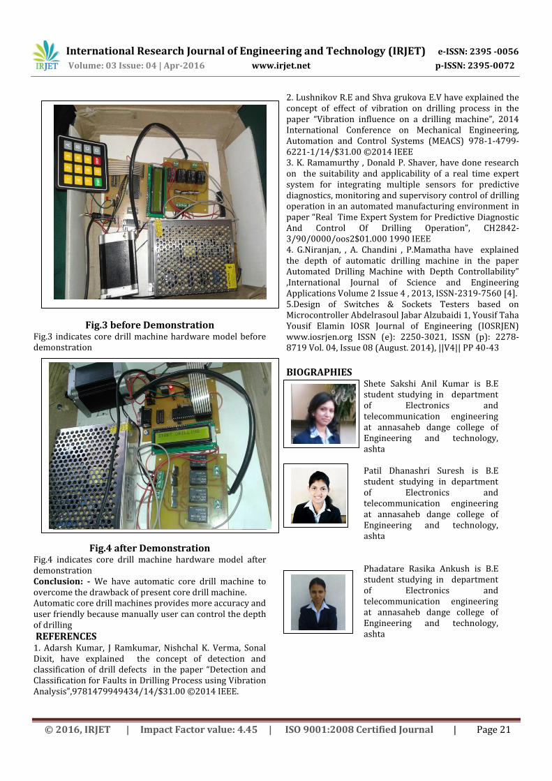
Fig.3 before Demonstration Fig.3 indicates core drill machine hardware model before demonstration
Fig.4 after Demonstration
Fig.4 indicates core drill machine hardware model after demonstration Conclusion: - We have automatic core drill machine to overcome the drawback of present core drill machine. Automatic core drill machines provides more accuracy and user friendly because manually user can control the depth of drilling
REFERENCES 1. Adarsh Kumar, J Ramkumar, Nishchal K. Verma, Sonal Dixit, have explained the concept of detection and classification of drill defects in the paper “Detection and Classification for Faults in Drilling Process using Vibration Analysis”,9781479949434/14/$31.00 ©2014 IEEE.
2. Lushnikov R.E and Shva grukova E.V have explained the concept of effect of vibration on drilling process in the paper “Vibration influence on a drilling machine”, 2014 International Conference on Mechanical Engineering, Automation and Control Systems (MEACS) 978-1-4799-6221-1/14/$31.00 ©2014 IEEE 3. K. Ramamurthy , Donald P. Shaver, have done research on the suitability and applicability of a real time expert system for integrating multiple sensors for predictive diagnostics, monitoring and supervisory control of drilling operation in an automated manufacturing environment in paper “Real Time Expert System for Predictive Diagnostic And Control Of Drilling Operation”, CH2842-3/90/0000/oos2$01.000 1990 IEEE 4. G.Niranjan, , A. Chandini , P.Mamatha have explained the depth of automatic drilling machine in the paper Automated Drilling Machine with Depth Controllability” ,International Journal of Science and Engineering Applications Volume 2 Issue 4 , 2013, ISSN-2319-7560 [4]. 5.Design of Switches & Sockets Testers based on Microcontroller Abdelrasoul Jabar Alzubaidi 1, Yousif Taha Yousif Elamin IOSR Journal of Engineering (IOSRJEN) www.iosrjen.org ISSN (e): 2250-3021, ISSN (p): 2278-8719 Vol. 04, Issue 08 (August. 2014), ||V4|| PP 40-43
BIOGRAPHIES Shete Sakshi Anil Kumar is B.E
student studying in department of Electronics and telecommunication engineering at annasaheb dange college of Engineering and technology, ashta
Patil Dhanashri Suresh is B.E student studying in department of Electronics and telecommunication engineering at annasaheb dange college of Engineering and technology, ashta
Phadatare Rasika Ankush is B.E student studying in department of Electronics and telecommunication engineering at annasaheb dange college of Engineering and technology, ashta

International Research Journal of Engineering and Technology (IRJET) e-ISSN: 2395 -0056
Volume: 03 Issue: 04 | Apr-2016 www.irjet.net p-ISSN: 2395-0072
© 2016, IRJET | Impact Factor value: 4.45 | ISO 9001:2008 Certified Journal | Page 22
Mr.Sachin S. Patil working as an assistant professor in department of Electronics and telecommunication engineering at annasaheb dange college of Engineering and technology, ashta since 2008.He has attended 4 internationational conferences and 4 national conferences.He has published 10 papers in international journals. He awarded as Young investigator in IRNET international conference at Nagpur.