automatic conrol valves fire protection ...with the 2017 acquisition of singer valve, mueller co....
TRANSCRIPT

UL / FM G-1
Page G-1-1
SECTION
Shaded area indicates changeFIRE PROTECTION PRODUCTS Rev. 8-17
MUELLER®
AUTOMATIC CONROL VALVES DESIGN FEATURES
Mueller Automatic Control ValvesWith the 2017 acquisition of Singer Valve, Mueller Co. designs and manufactures automatic control valves for the global water industry. Since 1957, our pilot operated diaphragm control valves have been installed on virtually every continent around the world. Whether it is water loss management in Southeast Asia, water conservation concerns in Saudi Arabia, urban distribution demands in the United States or fire valves in Indonesia or South Korea, we provide water management solutions to governments, cities, companies and contractors around the world. Many of our innovative products are ones that have been born out of our inherent desire to solve an application challenge. Presented with a problem, our team of electronic, instrumentation and control valve specialists are relentless in their research and design until they find a solution.
❏ AISI Stainless Steel Components - our AISI 316 stainless steel spring and stem are corrosion resistent. The AISI 316 stainless steel seat ring is guaranteed for the life of the valve.❏ Removable Stem Cap - the removable, separate stem cap reduces bent stems, which reduces inspection & assembly time.❏ Stainless Steel External Fasteners - stainless steel external fasteners prevent rust, reducing maintenance.❏ Smaller, Lighter Cover - smaller, lighter cover improves worker safety and reduces maintenance.❏ Removable Bonnet - bonnet removes easily thanks to locating-pin technology.❏ Anti-Vibration Fasteners - stainless steel anti-vibration fasteners create a dependable maintenance-free seat.
❏ Extra Threaded Taps - extra threaded taps on main valve allow for easy re-orientation of pilot system.❏ Oversized Wrench Flat - accessible oversized wrench flat means easy disassembly of inner valve.❏ Rolling Diaphram Design* - exclusive rolling diaphram design offers unequalled low flow stability.❏ Fusion Epoxy Coating - coated inside and outside for improved flow and resistance to wear.❏ EPDM/Buna-N Elastomer Diaphram - EPDM/Buna-N elastomer diaphram is chlorine and chlormine resistant.
*Not available in all size/modelcombinations. Consult with Mueller Co.

UL / FMG-1
Page G-1-2
SECTION
FIRE PROTECTION PRODUCTSShaded area indicates change
MODEL M106-RPS-8700APRESSURE RELIEF VALVE
Rev. 8-17
M106-RPS-8700AThe M106-RPS-8700A pressure relief valve, which is UL/FM labelled and listed, automatically relieves excess pressure in the fire protection system to discharge. The RPS series valves will also automatically modulate to relieve excess pump capacity during pump start up and shut down, allowing the pump to operate without causing surges.These relief valves are based on the M106-PG or MA106-PG main valves and come in complete range of sizes from 2-1/2 in/65 mm to 8 in/200 mm. In typical pressure relief application, the angle style MA106-RPS-8700A is often the preferred selection.
Features• UL Listed to ANSI/UL 1478A FM Approved to FM 1361• Reliable diaphragm actuated• Hydraulically operated design• Class 150 and 300 flanges• Stainless steel fasteners• Heat fused red epoxy coating• Available in globe and angle style
Standard materials for pilot system components• ASTM B62 bronze or ASTM B16 brass • AISI 303/316 stainless steel trim • Buna-N/EPDM diaphragm and seals
12
3
45
6
2 2
Schematic A-8700A
Schematic Drawing1. Main Valve - M106-PG, or MA106-PG, Flanged 2-1/2 in/65 mm to 8 in/200 mm2. Isolation Valve - lockable (optional)3. Strainer - standard 4 in/100 mm and larger4. Fixed Restriction- 1/8 in/3.2 mm5. Model M852-B Closing Speed Control6. Model M81-RP pilot - 30 to 200 psig/2.07 to 13.8 barg - optional 100 to 300 psig/6.9 to 20.7 barg

UL / FM G-1
Page G-1-3
SECTION
Shaded area indicates changeFIRE PROTECTION PRODUCTS
MUELLER®
AUTOMATIC CONROL VALVESRev. 6-17
www.muellercompany.com • [email protected]

UL / FMG-1
Page G-1-4
SECTION
FIRE PROTECTION PRODUCTSShaded area indicates change
Rev. 7-17
MODEL M18-FRPRESSURE RELIEF VALVE
M18-FR The M18-FR is a remote sensing, high capacity, spring and diaphragm operated, normally closed valve. The inner valve is held closed by the spring. When the sensed pressure increases above the spring setting, the valve opens.
Features• Available in globe and angle style• Available sizes ½ inch and ¾ inch• Direct acting• Drip tight closing• Accurate pressure control• UL listed to ANSI/UL 1478A FM approved to FM 1359
Specifications • The normally closed valve shall be of stainless steel construction with a spring to adjust the opening pressure. • The inner valve shall be of stainless steel 316 construction and the inner valve shall have EPDM resilient compound for seating. • A separate port will sense pressure to open the valve when system pressure exceeds the valve set-point.• Maximum working temperature: 180° F/82° C• Maximum working pressure: 400 psig/27.6 barg
Spring Range Approximate PSI Per Turn
Standard 20 to 200 psig 1.38 to 13.8 barg) 22 psig (1.52 barg)
Optional
10 to 75 psig(0.69 to 5.17 barg) 9 psig (0.62 barg)
100 to 300 psig(6.9 to 20.7 barg) 49 psig (3.38 barg)
Flow Rates
Size Cv Max Flow (GPM)1/2" 6.8 70
1/2" angle 6.9 763/4" 8.3 84
3/4" angle 8.4 88

UL / FM G-1
Page G-1-5
SECTION
Shaded area indicates changeFIRE PROTECTION PRODUCTS
MODEL M18-FRPRESSURE RELIEF VALVE
Rev. 6-17
'C'
1/2 OR 3/4 NPTEND CONNECTIONS
GAUGE PORT1/8 NPT
'B'
1/4 NPT PORTS 'A'
'C'
1/2 OR 3/4 NPTEND CONNECTIONS
GAUGE PORT1/8 NPT
'B'
1/4 NPT PORTS 'A'
US Unite SI UnitsA 3.50" 90 mmB 9.06" 230 mmC 3.19" 81 mm
Weight 4.05 lbs. 1.8 kg
Schematic Drawing
Part Description1 Body2 Plug (stainless steel)3 Inner valve (18FR)4 Resilient disc5 Bushing (threaded)6 Clamp plate (lower)7 Plug (1/8 NPT stainless steel)8 Clamp plate9 Spring step10 Spring11 Spring casing12 Hbolt 0.375-16x2.06 (machined)13 Diaphram pilot (EPDM)14 Retainer disc15 Nut - hex jam 3/8-16 UNC16 Nut - hex 1/4-20 UNC17 Socket head cap screw18 O-ring19 O-ring20 Screw - hex head21 Tag (Mueller)22 Tag (UL Approved)23 Rivet U drive24 Plug - 1/4 NPT

UL / FMG-1
Page G-1-6
SECTION
FIRE PROTECTION PRODUCTSShaded area indicates change
MODEL M016-PR-10159 UL/M106-PR-8702A ULC
PRESSURE REDUCING VALVE
M016-PR-10159 UL / M106-PR-8702A ULCThe M106-PR, which is UL and ULC labelled and listed, is ideal for automatically reducing a higher inlet pressure to a steady lower discharge pressure, regardless of fluctuations in flow or inlet pressure. The valves are based on the M106-PG or MA106PG control valves and are available in a complete range of sizes from 2 in/50 mm to 8 in/200 mm (sizes depend on UL classification). In typical pressure reducing applications, the globe style M106-PR is often the preferred valve style.
Features• UL and ULC listed to ANSI/UL 1468, 1739• Reliable diaphragm actuated• Hydraulically operated design• Class 150, 300 flanges, grooved & threaded• Stainless steel fasteners• Heat fused red epoxy coating• Available in globe and angle style
Standard materials for pilot system components• ASTM B62 bronze or ASTM B16 brass • AISI 303/316 stainless steel trim • Buna-N / EPDM diaphragm and seals
Schematic Drawing1. Main Valve - Model M106-PG, SPG or GE, Globe or Angle, 2 in/50 mm - 8 in/200 mm UL (2 in/50 mm, 8 in/200 mm ULC) Grooved - 2 in/50 mm to 8 in/200 mm, Globe style only2. Lockable Isolation Valve MJ0044A (optional)3. Strainer MJ0098A - standard 4 in/100 mm & larger4. Fixed Restriction5. Pressure Reducing Pilot Model M161PR (UL),
M160PR (ULC) • Range: 30 to 165 psig/2.06 to 11.37 barg (UL) • Range: 20 to 200 psig/1.38 to 13.8 barg (ULC) • Optional 100-300 psig/3.89 to 20.68 barg (ULC
Note: Maximum outlet setting for both UL & ULC pilots is 165 psig/11.37 barg
5
1
23
4
22
Schematic A-10159B UL
Note: UL listed valves use rolling diaphragm on 6 in/150 mm and 8 in/200 mm valves. ULC listed valves use flat diaphragms only. For UL dimensions, ULC dimensions and Grooved dimensions, see page 26.
PR-10159 - UL Listed
Valve SizeMaximum Pressure
Class 150 Class 3002 in/50mm - 4 in/100 mm 175 psig/12.06 barg 300 psig/20.68 barg6 in/150mm - 8 in/200 mm 175 psig/12.06 barg -
PR-8702A - ULC Listed
Valve SizeMaximum Pressure
Class 150 Class 300Globe 2 in/50mm - 8 in/200 mm 175 psig/12.06 barg 400 psig/27.60 bargAngle 2 in/50mm - 8 in/200 mm 175 psig/12.06 barg 400 psig/27.60 barg
Rev. 8-17

UL / FM G-1
Page G-1-7
SECTION
Shaded area indicates changeFIRE PROTECTION PRODUCTS
MODEL M106-F-TYPE 4MODULATING FLOAT VALVE
M106-F-TYPE 4The Model M106-F-Type 4 modulating float valves are based on the M106-PG main valve. They are ideal for balancing the inflow and outflow demand into the storage tank and maintaining level at the designated maximum. The valve closes drip-tight at the maximum level and modulates to maintain the tank level. The float pilot is remotely installed at the high level in the storage tank. Pilot connections to the main valve are connected in the field. As the tank level drops the main valve is opened proportionally to increase the filling rate. Movement of the main stem alters the size of the closing restriction, interrupting the tendency of the valve to hunt.
Features• Maintains relatively constant level• Automatic compensation for level draw-down• Standard integral damping reduces hunting• Drip-tight at high level shut-off• Low supply pressure options
Standard materials for pilot system components• ASTM B62 bronze or ASTM B16 brass • Stainless steelNote: The stilling well and the connections between main valve and pilotcompleted by others.
Schematic A-0608D
Schematic Drawing1. Main Valve - M106-PG, SPG or GE, Internal Needle Stem Valve (INSV) built into stem Available in 1/2 in/15 mm to 8 in/200 mm, FNTP 1/2 in/15 mm to 1 in/15 mm, Flanged 1-1/2 in/40 mm to 8 in/200 mm, Grooved 2 in/50 mm to 8 in/200mm, Globe style only2. Isolation valve3. Strainer - 40 mesh stainless steel screen4. R400 Float Pilot comes with plastic floatNote: Schematic shown for 2.5 in/65 mm and larger
4
1
232
Rev. 6-17

UL / FMG-1
Page G-1-8
SECTION
FIRE PROTECTION PRODUCTSShaded area indicates change
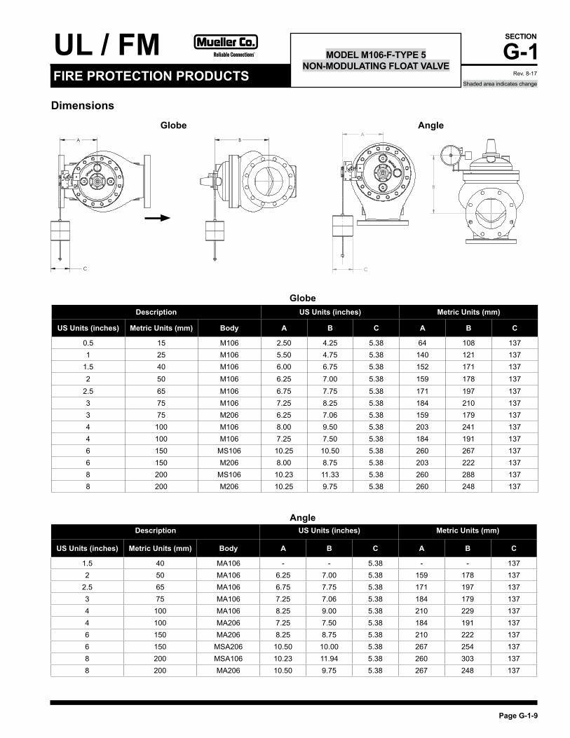
MODEL M106-F-TYPE 5NON-MODULATING FLOAT VALVE
M106-F-TYPE 5The M106-F-Type 5 non-modulating float valves are based on the M106-PG main valve. It is ideal for allowing normal forward flow to fill water tanks to a desired high level and where the pilot and valve of the storage tanks are easily accessible. The valve functions as a two position valve, either open or closed. The valve remains closed when the tank level drops, until the float reaches the pre-determined adjustable minimum tank level. The F-Type 5 valve then opens to refill the tank and closes tightly when high water level is achieved.
Features• No overflow, drip-tight closure• Adjustable draw down• Easily adjustable level settings• Low supply pressure options
Standard materials for pilot system components• ASTM B62 bronze or ASTM B16 brass • Stainless steelNote: The stilling well and the connections between main valve and pilot completed by others.
Schematic Drawing1. Main Valve - M106-PG, SPG or GE Available in 1 in/25mm to 8 in/200 mm, FNTP 1 in/25 mm to 3 in/80 mm, Flanged 1 1/2 in/40 mm to 8 in/200 mm, Grooved 2 in/50 mm to 8 in/200 mm, Globe style only2. Isolation valve3. Strainer - 40 mesh stainless steel screen4. Model M43 Float Pilot comes with Stainless Steel float, 4 ft/1.2 m stainless steel rod - 8” (200mm) & larger, - 2 ft/600 mm stainless steel rod – 6” (150 mm) and smallerNote: Schematic shown for 2.5 in/65 mm and larger
1
2
4
3 2
B
INX
Schematic A-0421C
8" (200mm) stilling well must be provided around float.
Rev. 8-17
UL / FM G-1
Page G-1-9
SECTION
Shaded area indicates changeFIRE PROTECTION PRODUCTS
MODEL M106-F-TYPE 5NON-MODULATING FLOAT VALVE
Dimensions
A
C
B
C
A B
Globe Angle
Description US Units (inches) Metric Units (mm)
US Units (inches) Metric Units (mm) Body A B C A B C
0.5 15 M106 2.50 4.25 5.38 64 108 1371 25 M106 5.50 4.75 5.38 140 121 137
1.5 40 M106 6.00 6.75 5.38 152 171 1372 50 M106 6.25 7.00 5.38 159 178 137
2.5 65 M106 6.75 7.75 5.38 171 197 1373 75 M106 7.25 8.25 5.38 184 210 1373 75 M206 6.25 7.06 5.38 159 179 1374 100 M106 8.00 9.50 5.38 203 241 1374 100 M106 7.25 7.50 5.38 184 191 1376 150 MS106 10.25 10.50 5.38 260 267 1376 150 M206 8.00 8.75 5.38 203 222 1378 200 MS106 10.23 11.33 5.38 260 288 1378 200 M206 10.25 9.75 5.38 260 248 137
Description US Units (inches) Metric Units (mm)
US Units (inches) Metric Units (mm) Body A B C A B C
1.5 40 MA106 - - 5.38 - - 1372 50 MA106 6.25 7.00 5.38 159 178 137
2.5 65 MA106 6.75 7.75 5.38 171 197 1373 75 MA106 7.25 7.06 5.38 184 179 1374 100 MA106 8.25 9.00 5.38 210 229 1374 100 MA206 7.25 7.50 5.38 184 191 1376 150 MA206 8.25 8.75 5.38 210 222 1376 150 MSA206 10.50 10.00 5.38 267 254 1378 200 MSA106 10.23 11.94 5.38 260 303 1378 200 MA206 10.50 9.75 5.38 267 248 137
Globe
Angle
Rev. 8-17

UL / FMG-1
Page G-1-10
SECTION
FIRE PROTECTION PRODUCTSShaded area indicates change
MODEL M106-A-TYPE 2 ONE-WAY FLOW ALTITUDE CONTROL VALVE
KX
Ex
2 6
4
3
5
7 6
9
6
DRAIN
TO STORAGE TANK
Schematic Drawing1. Main Valve - M106-PG, SPG or GE with X107 visual position indicator. Available in 2 in/50 mm to 8 in/200 mm, FNTP 2 in/50 mm to 3 in/80 mm, Flanged 2-1/2 in/ 63 mm to 8 in/200 mm, Grooved 2 in/50 mm to 8 in/200 mm, Globe style only2. Strainer - 40 mesh stainless steel screen3. Model M301-4 altitude pilot4. Closing speed control5. Altitude Gauge - dual scale - feet and meter6. Isolation valve7. Union8. Sensing connection to storage tank (complete in field by others)9. Isolation valve
M106-A-TYPE 2The M106-A-Type 2 altitude control valves are based on the M106-PG main valve, and is ideal for maintaining a preset maximum water level. The valve functions as a two position control valve, either fully open or fully closed. The Type 2 valve allows normal forward flow to fill the storage tank to the maximum level and then closes drip-tight at the set-point. It opens to refill the tank once the level drops a fixed distance below the high water level. Note: This valve does not operate as a check valve to prevent reverse flow.
Features• No overflows - high level shut-off maintained to close tolerances• Superior repeatability• Positive shut-off• Easily serviceable at ground level
Standard materials for pilot system components• Ductile iron• Brass • Stainless steel• Copper
Schematic A-0413C
Rev. 7-17

UL / FM G-1
Page G-1-11
SECTION
Shaded area indicates changeFIRE PROTECTION PRODUCTS
MODEL M106-A-TYPE 4 ONE-WAY FLOW ALTITUDE CONTROL VALVE
WITH DIFFERENTIAL CONTROL
KX
Ex
3 2
4
5
7
11 2
8
2
DRAIN
TO STORAGE TANK
10
6
Schematic A-0415C
Schematic Drawing1. Main Valve - M106-PG, SPG or GE with X107 visual position indicator. Available in 2 in/50 mm to 8 in/200 mm, FNTP 2 in/50 mm to 3 in/80 mm, Flanged 2-1/2 in/ 63 mm to 8 in/200 mm, Grooved 2 in/50 mm to 8 in/200 mm, Globe style only2. Isolation valve3. Strainer - 40 mesh stainless steel screen4. Closing speed control5. Model M301-4 altitude pilot6. Model M106-RD differential pilot7. Altitude gauge - dual scale - feet & meter8. Sensing connection to storage tank (complete in field)9. Model M10 check valve10. Union
M106-A-TYPE 4The M106-A-Type 4 altitude control valves are based on the M106-PG main valve, and is ideal for maintaining a preset maximum water level. The valve functions as a two position control valve, either fully open or fully closed.The Type 4 allows normal forward flow to fill the storage tank to the maximum level, then closes drip-tight at the set-point. It opens to refill the tank once the level drops an adjustable amount below the high water level. Note: Distribution from the storage tank is through a separate pipeline. This valve does not operate as a check valve to prevent reverse flow.
Features• No overflows• Adjustable draw-down level (differential) set-point• Superior repeatability• Positive shut-off• Adjustable draw-down for improved water cycling
Standard materials for pilot system components• Ductile iron• Brass • Stainless steel• Copper
Rev. 7-17

UL / FMG-1
Page G-1-12
SECTION
FIRE PROTECTION PRODUCTSShaded area indicates change
MODEL M106-PG/MS106-PG &M106-GE FULL PORT, SINGLE CHAMBER,
HYDRAULICALLY OPERATED VALVE
Schematic Drawing1. Removeable stem cap2. ASTM A536 ductile iron construction3. Diaphram Buna-N or EPDM4. Buna-N or EPDM resilient disc5. AISI 316 stainless steel seat6. AISI 316 stainless steel stem7. HFE coating AKZO RAL 3000 Fire Red
M106-PG / MS106-PG & M106-GEThe M106-PG series control valve is designed to suit a large variety of applications such as pressure, flow or level control. This hydraulically operated valve introduces or releases water from the control chamber above the diaphragm to effectively maintain accurate water control.
Features• Available in Globe & Angle styles
1
2
3
4
5
6
7
MS106-PG
M106-PG Globe - Flat
Rev. 6-17

UL / FM G-1
Page G-1-13
SECTION
Shaded area indicates changeFIRE PROTECTION PRODUCTS
MODEL M106-PG/MS106-PG &M106-GE FULL PORT, SINGLE CHAMBER,
HYDRAULICALLY OPERATED VALVE
Alternate Models
MS106-PG Angle MS106-PG Threaded MS106-GE Globe
Available StylesDuctile Iron Stainless Steel
Threaded Flanged Grooved Threaded FlangesGlobe 1" - 3" (25-80mm) 1-1/2" - 36" (40-900mm) 2" - 8" (50-200mm) 1/2" - 2" (15-50mm) 1-1/2" - 6" (40-150mm)
Angle 1" - 3" (25-80mm) 2" - 12", 16"(50-300mm, 400mm) - - -
Valve Sizes and Materials
Ductile Iron
Part DescriptionMaterial
Standard Optional1 Valve body, Cover 65-45-12 ductile iron -2 Seat ring 316 stainless steel -3 Disc retainer B16 brass / B62 bronze / A536 ductile iron Stainless steel4 Stem 316 stainless steel -5 Stem nut B16 brass 316 stainless steel6 Spring 316 stainless steel -7 Guide bushings B16 brass or SAE 660 bronze Stainless steel8 Diaphram EPDM BUNA-N / Vitron (limited sizes)9 Resilient disc EPDM BUNA-N / Vitron (limited sizes)10 Coating HFE coating AKZO RAL 3000 fire red (Consult factory)11 Fasteners 18-8 stainless steel 316 stainless steel
Valve Styles
Valve Components
Rev. 6-17

UL / FMG-1
Page G-1-14
SECTION
FIRE PROTECTION PRODUCTSShaded area indicates change
MODEL M106-GE/M206-GEGROOVED ENDS
M106-GE / M206-GEFor use with grooved Iron Pipe Size (IPS) Pipe Coupling Products, grooved ends allows you to benefit from the simplicity and convenience of grooved end piping and fittings in an automatic control valve. There are a wide range of applications where grooved ends are relevant, but typical applications include municipal water, waste water, fire protection and plumbing.
Grooved ends come in the following size ranges: • 2 in/50 mm – 8 in/200 mm Standard cut groove specifications for steel and other IPS pipe will apply, unless otherwise specified • Main valve body shall be complete with grooved ends. • Standard cut groove specifications will be “steel and other IPS pipe” only unless otherwise specified.
Features• Convenient system and equipment access for ease of alignment and installation• Improved flexibility with expansion, contraction and deflection• Seismic stress absorption• Eliminated unions• Grooved to ANSI/AWWA C606
MS106-GE Globe
Rev. 6-17

UL / FM G-1
Page G-1-15
SECTION
Shaded area indicates changeFIRE PROTECTION PRODUCTS
MODEL M106-EDV-A-10507AELECTRONICALLY OPERATED
DELUGE VALVE
Schematic A-10507A
Schematic Drawing1. Main Valve – Model M106-PG-UL-Deluge2. Strainer3. Fixed restriction4. M82-PR-UL Pilot5. Solenoid Valve – normally open6. Manual Emergency Override – normal position closed
M106-EDV-A-10507AModel M106 EDV-A-10507A Electric Solenoid control valve is based on the Model M106 PG-UL Deluge main valve.The solenoid pilot provides on-off position operation. The solenoid either admits inlet pressure into the main valve operating chamber from the inlet of the main valve via a high capacity relay valve or releases pressure from the relay valve and therefore the main valve operating chamber. This either opens or closes the main valve. The pilot system is usually piped to discharge to drain (atmosphere).The M106 EDV-A-10507A is available with the main valve closed when the solenoid is de-energized (NC-normally closed. This refers to the main valve, not the solenoid).
Features• UL listed to ANSI/UL 260• Reliable diaphragm actuated• Hydraulically operated design• ANSI class 150, 300 flanges and grooved ends• Stainless steel fasteners• Heat fused red epoxy coating• Available in globe style, 3 in/80mm - 8 in/200mm
Standard materials for pilot system components• ASTM B62 bronze or ASTM B16 brass • AISI 303/316 stainless steel trim• Buna-N/EPDM diaphragm and seals
All valves have HFE coating AKZO RAL 3000 Fire Red (not intended for drinking water).
MS106-EDV-A-10507A Globe
Rev. 8-17

UL / FMG-1
Page G-1-16
SECTION
FIRE PROTECTION PRODUCTSShaded area indicates change
MODEL M106-PDV-A-10508APNEUMATICALLY OPERATED
REMOTE CONTROL DELUGE VALVE
Schematic A-10508A
Schematic Drawing1. Main Valve – Model M106-PG-UL-Deluge2. Strainer3. Ejector - MX141A4. M82-PR-UL Pilot5. Manual Emergency Override – normal position closed
M106-PDV-A-10508AModel M106 PDV-A-10508A Pneumatically Operated Control valve is based on the Model M106 PG-UL Deluge main valve.The high capacity relay valve provides on-off position operation. The high capacity relay valve, using an independent air supply, either admits inlet pressure into the main valve operating chamber from the inlet of the main valve or releases pressure from the operating chamber. The pilot system is usually piped to discharge to drain (atmosphere).
Features• UL listed to ANSI/UL 260• Reliable diaphragm actuated• Hydraulically operated design• ANSI class 150, 300 flanges and grooved ends• Stainless steel fasteners• Heat fused red epoxy coating• Available in globe style, 3 in/80mm - 8 in/200mm
Standard materials for pilot system components• ASTM B62 bronze or ASTM B16 brass • AISI 303/316 stainless steel trim• Buna-N/EPDM diaphragm and seals
All valves have HFE coating AKZO RAL 3000 Fire Red (not intended for drinking water).
M106-PDV-A-10508A Globe
Rev. 8-17

UL / FM G-1
Page G-1-17
SECTION
Shaded area indicates changeFIRE PROTECTION PRODUCTS
MODEL M106-EPDV-A-10506AELECTRIC/PNEUMATICALLY OPERATED DELUGE VALVE
Schematic A-10506A
Schematic Drawing1. Main Valve – Model M106-PG-UL-Deluge2. Strainer3. Fixed Restriction4. M82-PR-UL Pilot5. Solenoid Valve – normally open6. Manual Emergency Override – normal position closed
M106-EPDV-A-10506AModel M106 EPDV-A-10506A Pneumatic/Electric Solenoid control valve is based on the Model M106 PG-UL Deluge main valve.The solenoid pilot provides on-off position operation. The solenoid, using an independent air supply, either admits inlet pressure into the main valve operating chamber from the inlet of the main valve via a high capacity relay valve or releases pressure from the relay valve and therfore the main valve operating chamber. This either opens or closes the main valve. The pilot system is usually piped to dis-charge to drain (atmosphere).The M106 EPDV-A-10506A is available with the main valve closed when the solenoid is de-energized (NC-normally closed. This refers to the main valve, not the solenoid).
Features• UL listed for fire extinguishing systems• Reliable diaphragm actuated• Hydraulically operated design• ANSI class 150, 300 flanges and grooved ends• Stainless steel fasteners• Heat fused red epoxy coating• Available in globe style, 3 in/80mm - 8 in/200mm
Standard materials for pilot system components• ASTM B62 bronze or ASTM B16 brass • AISI 303/316 stainless steel trim• BUNA-N/EPDM diaphragm and seals
All valves have HFE coating AKZO RAL 3000 Fire Red (not intended for drinking water).
MS106-EPDV-A-10508A Globe
Rev. 8-17

UL / FMG-1
Page G-1-18
SECTION
FIRE PROTECTION PRODUCTSShaded area indicates change
MODEL M106-PG FULL PORT, SINGLE CHAMBER, HYDRAULICALLY
OPERATED VALVE
ANSI Valve Data (US Units)
Size DWG Standard Flat Diaphragm SystemInches REF ANSI 1/2 in 3/4 in 1 in 1-1/4 in 1-1/2 in 2 in 2-1/2 in 3 in 4 in 6 in 8 in Globe Dimensions All figures shown in inches unless otherwise statedLay Length A FNPT 3.50 3.50 6.75 6.75 6.75 9.38 11.00 13.50 - - -
Centerline to Bottom D FNPT 1.20 1.20 2.50 2.50 2.50 2.75 3.38 3.68 - - -
Lay Length A 150F - - - - 8.50 9.38 11.00 12.00 15.00 20.00 25.38
Centerline to Bottom D 150F - - - - 2.75 3.00 3.50 3.75 4.60 5.60 7.63
Lay Length A 300F - - - - 9.00 10.00 11.63 13.25 15.63 21.00 26.38
Centerline to Bottom D 300F - - - - 3.25 3.25 3.75 4.13 5.09 6.34 7.88
Angle DimensionsCenter Inlet to Discharge B FNPT - - 3.38 3.38 3.38 4.69 5.50 6.63 - - -
Center Discharge to Inlet F FNPT - - 3.00 3.00 3.00 3.25 4.00 4.63 - - -
Center Inlet to Discharge B 150F - - - - - 4.75 5.50 6.06 7.50 10.00 12.75
Center Discharge to Inlet F 150F - - - - - 3.25 4.00 4.06 5.00 6.00 8.00
Center Inlet to Discharge B 300F - - - - - 5.00 5.88 6.43 7.88 10.50 13.25
Center Discharge to Inlet F 300F - - - - - 3.50 4.31 4.43 5.31 6.50 8.50
Common Dimensions (Globe & Angle)Width C 3.00 3.00 4.88 4.88 6.13 6.5 8.19 9.25 10.88 16.75 21.63
Height (To Stem Cap) Globe E 3.06 3.06 4.38 4.38 4.38 6.75 9.5 10.5 12.25 11.75 14.91
Height (To Stem Cap) Angle E - - 4.38 4.38 4.38 4.75 7.71 10.5 12.25 11.75 14.91
Body Port Tapping FNPT 1/4 1/4 3/8 3/8 3/8 3/8 3/8 3/8 3/8 3/8 1/2
Stem Cap Plug MNPT 1/4 1/4 3/8 3/8 3/8 3/8 3/8 3/8 3/8 3/8 3/8
Cover Port Tapping FNPT - - 3/8 3/8 3/8 3/8 3/8 3/8 3/8 1/2 1/2
Valve Stroke 1/4 1/4 1/2 1/2 1/2 9/16 15/16 1-1/8 1-7/16 1-11/16 2-7/8
Displaced Bonnet Volume (Gallons) 0.002 0.002 0.007 0.007 0.007 0.02 0.1 0.1 0.2 0.6 1.7
Approximate Shipping Weight (Lbs) 10 10 20 20 20 40 65 100 175 400 650
Flow Capacities (USGPM) Globe & Angle
Cv - Globe 28 30 32 55 80 110 200 460 800
Cv - Angle 24 24 26 63 90 135 230 535 950
Continuous (Globe) 49 93 125 210 300 460 800 1800 3100
Intermittent (Globe) 61 120 160 260 375 575 1000 2250 3875
Momentary (Globe) 110 170 250 470 670 1030 1800 4000 7000
Maximum Pressure Ratings (Ductile Only)
PSIG1 FNPT 400 400 400 400 400 400 - - -
PSIG 150F - - 250 250 250 250 250 250 250
PSIG1 300F - - 400 400 400 400 400 400 400
Maximum Temperature
Fahrenheit 180º 180º 180º 180º 180º 180º 180º 180º 180º
Globe Style Flat Diaphragm
Angle Style Flat Diaphragm
'A' 'B'
'E' 'E'
'F'
'B'
'E'
'F''D'
'A'
'E'
'D'
'C'
Flange Feetfor Safety andConvenience
FlangeDiameter
'D' Dim
'A' 'B'
'E' 'E'
'F'
'B'
'E'
'F''D'
'A'
'E'
'D'
'C'
Flow
Standard
Flow
Opposite
1Valves rated and stamped 400 psig as standard. Valves rated and stamped 600 psig on request.
Dimensions
Rev. 6-17
UL / FM G-1
Page G-1-19
SECTION
Shaded area indicates changeFIRE PROTECTION PRODUCTS
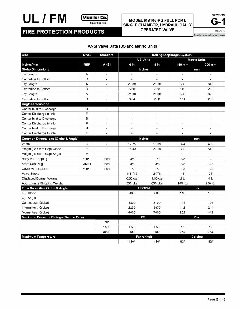
MODEL MS106-PG FULL PORT, SINGLE CHAMBER, HYDRAULICALLY
OPERATED VALVE
Size DWG Standard Rolling Diaphragm System
US Units Metric Units
Inches/mm REF ANSI 6 in 8 in 150 mm 200 mm
Globe Dimensions inches mm
Lay Length A - - - - -
Centerline to Bottom D - - - - -
Lay Length A - 20.00 25.38 508 645
Centerline to Bottom D - 5.60 7.63 142 200
Lay Length A - 21.00 26.38 533 670
Centerline to Bottom D - 6.34 7.88 161 200
Angle Dimensions
Center Inlet to Discharge B - - - - -
Center Discharge to Inlet F - - - - -
Center Inlet to Discharge B - - - - -
Center Discharge to Inlet F - - - - -
Center Inlet to Discharge B - - - - -
Center Discharge to Inlet F - - - - -
Common Dimensions (Globe & Angle) inches mm
Width C - 12.75 16.09 324 409
Height (To Stem Cap) Globe E - 15.43 20.19 392 513
Height (To Stem Cap) Angle E - - - - -
Body Port Tapping FNPT inch 3/8 1/2 3/8 1/2
Stem Cap Plug MNPT inch 3/8 3/8 3/8 3/8
Cover Port Tapping FNPT inch 1/2 1/2 1/2 1/2
Valve Stroke 1-11/16 2-7/8 43 73
Displaced Bonnet Volume 0.50 gal 1.00 gal 2 L 4 L
Approximate Shipping Weight 350 Lbs 650 Lbs 160 Kg 250 Kg
Flow Capacities Globe & Angle USGPM L/s
Cv - Globe 460 800 110 190
Cv - Angle - - - -
Continuous (Globe) 1800 3100 114 196
Intermittent (Globe) 2250 3875 142 244
Momentary (Globe) 4000 7000 252 442
Maximum Pressure Ratings (Ductile Only) PSI Bar
FNPT - - - -
150F 250 250 17 17
300F 400 400 27.6 27.6
Maximum Temperature Fahrenheit Celcius
180º 180º 82º 82º
ANSI Valve Data (US and Metric Units)
Rev. 6-17

UL / FMG-1
Page G-1-20
SECTION
FIRE PROTECTION PRODUCTSShaded area indicates change
Dimensions
MODEL M106-PG FULL PORT, SINGLE CHAMBER, HYDRAULICALLY
OPERATED VALVE
Globe Style Flat Diaphragm
Angle Style Flat Diaphragm
'A' 'B'
'E' 'E'
'F'
'B'
'E'
'F''D'
'A'
'E'
'D'
'C'
Flange Feetfor Safety andConvenience
FlangeDiameter
'D' Dim
'A' 'B'
'E' 'E'
'F'
'B'
'E'
'F''D'
'A'
'E'
'D'
'C'
Flow
Standard
Flow
Opposite
Size DWG Standard Flat Diaphragm System
mm REF ISO 15 mm 20 mm 25 mm 32 mm 40 mm 50 mm 65 mm 80 mm 100 mm
150 mm
200 mm
Globe Dimensions All figures show in mm unless otherwise statedLay Length A - 89 89 171 171 171 238 279 343 - - -
Centerline to Bottom D - 31 31 64 64 64 70 86 93 - - -
Lay Length A - - - - - 229 238 279 318 381 508 645
Centerline to Bottom D - - - - - 83 76 89 100 117 142 200
Lay Length A - - - - - 229 238 279 318 397 533 670
Centerline to Bottom D - - - - - 83 76 89 100 129 161 200
Angle DimensionsCenter Inlet to Discharge B - - - 86 86 86 119 140 168 - - -
Center Discharge to Inlet F - - - 76 76 76 83 102 118 - - -
Center Inlet to Discharge B - - - - - - 121 140 163 191 254 324
Center Discharge to Inlet F - - - - - - 83 102 113 127 152 203
Center Inlet to Discharge B - - - - - - 121 140 163 200 267 337
Center Discharge to Inlet F - - - - - - 83 102 113 135 165 216
Common Dimensions (Globe & Angle)Width C - 76 76 124 124 156 152 208 235 276 425 549
Height (To Stem Cap) Globe E - 78 78 111 111 111 121 191 203 232 298 379
Height (To Stem Cap) Angle E - - - 111 111 111 121 191 203 232 298 379
Body Port Tapping FNPT Inches 1/4 1/4 3/8 3/8 3/8 3/8 3/8 3/8 3/8 3/8 1/2
Stem Cap Plug MNPT Inches 1/4 1/4 3/8 3/8 3/8 3/8 3/8 3/8 3/8 3/8 3/8
Cover Port Tapping FNPT Inches - - 3/8 3/8 3/8 3/8 3/8 3/8 3/8 1/2 1/2
Valve Stroke mm 6.4 6.4 13 13 13 14 25 29 37 43 73
Displaced Bonnet Volume (Litres) 0.01 0.01 0.03 0.03 0.03 0.1 0.3 0.3 0.8 2.1 6.3
Approximate Shipping Weight (Kilograms) 5 5 9 9 9 18 29 45 79 181 295
Flow Capacities (L/s) Globe & AngleKv - Globe - - 6.6 7.1 7.6 13 19 26 47 110 190
Kv - Angle - - 5.7 5.7 6.2 15 21 32 55 123 225
Continuous (Globe) - - 3 6 8 13 19 29 50 114 196
Intermittent (Globe) - - 4 8 10 16 24 36 63 142 244
Momentary (Globe) - - 7 11 16 30 42 65 114 252 442
Maximum Pressure Ratings (Ductile Only)Barg1 - 27.6 27.6 27.6 27.6 27.6 27.6 27.6 27.6 - - -
Barg - - - - - 16 16 16 16 16 16 16
Barg1 - - - - - 25 25 25 25 25 25 25
Maximum TemperatureCelcius 82º 82º 82º 82º 82º 82º 82º 82º 82º 82º 82º
ANSI Valve Data (Metric Units)
Rev. 8-17
1Valves rated and stamped 27.6 barg as standard. Valves rated and stamped 41 barg on request*UL/FM Relief rated to 20.7 barg

UL / FM G-1
Page G-1-21
SECTION
Shaded area indicates changeFIRE PROTECTION PRODUCTS
Dimensions
MODEL M106-PG - UL/FM RELIEF & ULC REDUCING ONLY FULL PORT,
SINGLE CHAMBER, HYDRAULICALLY OPERATED VALVE
Size DWG Standard Flat Diaphragm System
Inches REF ANSI 2 in 2-1/2 in 3 in 4 in 6 in 8 in
Globe Dimensions All figures show in inches unless otherwise stated
Lay Length A FNPT 9.38 11.00 13.50 - - -
Centerline to Bottom D FNPT 2.75 3.38 3.68 - - -
Lay Length A 150F 9.38 11.00 12.00 15.00 20.00 25.38
Centerline to Bottom D 150F 3.00 3.50 3.75 4.60 5.60 7.63
Lay Length A 300F 10.00 11.63 13.25 15.63 21.00 26.38
Centerline to Bottom D 300F 3.25 3.75 4.13 5.09 6.34 7.88
Angle Dimensions
Center Inlet to Discharge B FNPT 4.69 5.50 6.63 - - -
Center Discharge to Inlet F FNPT 3.25 4.00 4.63 - - -
Center Inlet to Discharge B 150F 4.75 5.50 6.06 7.50 10.00 12.75
Center Discharge to Inlet F 150F 3.25 4.00 4.06 5.00 6.00 8.00
Center Inlet to Discharge B 300F 5.00 5.88 6.43 7.88 10.50 13.25
Center Discharge to Inlet F 300F 3.50 4.31 4.43 5.31 6.50 8.50
Common Dimensions (Globe & Angle)
Width C - 6.50 8.19 9.25 10.88 16.75 21.63
Height (To Stem Cap) Globe E - 4.75 7.50 8.00 9.15 11.75 14.91
Height (To Stem Cap) Angle E - 4.75 7.50 8.00 9.15 11.75 14.91
Body Port Tapping FNPT 3/8 3/8 3/8 3/8 3/8 1/2
Stem Cap Plug MNPT 3/8 3/8 3/8 3/8 3/8 3/8
Cover Port Tapping FNPT 3/8 3/8 3/8 3/8 1/2 1/2
Valve Stroke 9/16 15/16 1-1/8 1-7/16 1-11/16 2-7/8
Displaced Bonnet Volume (Gallons) 0.02 0.1 0.1 0.2 0.6 1.7
Approximate Shipping Weight (Lbs) 40 65 100 175 400 650
Flow Capacities (USGPM) Globe & Angle
Cv - Globe 55 80 110 200 460 800
Cv - Angle 63 90 135 230 535 950
Continuous (Globe) 210 300 460 800 1800 3100
Intermittent (Globe) 260 375 575 1000 2250 3875
Momentary (Globe) 470 670 1030 1800 4000 7000
Maximum Pressure Ratings (Ductile Only)
PSIG1 FNPT 400 400 400 - - -
PSIG 150F 250 250 250 250 250 250
PSIG1 300F 400* 400* 400* 400* 400* 400*
Maximum Temperature
Fahrenheit 180º 180º 180º 180º 180º 180º
ANSI Valve Data (US Units)
1Valves rated and stamped 400 psig as standard. Valves rated and stamped 600 psig on request.*UL/FM Relief rated to 300 psig
Rev. 6-17

UL / FMG-1
Page G-1-22
SECTION
FIRE PROTECTION PRODUCTSShaded area indicates change
MODEL M106-PG - UL/FM RELIEF & ULC REDUCING ONLY FULL PORT,
SINGLE CHAMBER, HYDRAULICALLY OPERATED VALVE
Size DWG Standard Flat Diaphragm System
mm REF ANSI 50 mm 65 mm 80 mm 100 mm 150 mm 200 mm
Globe Dimensions All figures show in mm unless otherwise stated
Lay Length A FNPT 238 279 343 - - -
Centerline to Bottom D FNPT 70 86 93 - - -
Lay Length A 150F 238 279 305 381 508 645
Centerline to Bottom D 150F 76 89 95 117 142 200
Lay Length A 300F 254 295 337 397 533 670
Centerline to Bottom D 300F 83 95 105 129 161 200
Angle Dimensions
Center Inlet to Discharge B FNPT 119 140 168 - - -
Center Discharge to Inlet F FNPT 83 102 118 - - -
Center Inlet to Discharge B 150F 121 140 154 191 254 324
Center Discharge to Inlet F 150F 83 102 103 127 152 203
Center Inlet to Discharge B 300F 127 149 163 200 267 337
Center Discharge to Inlet F 300F 89 109 113 135 165 216
Common Dimensions (Globe & Angle)
Width C - 165 208 235 276 425 549
Height (to stem cap) Globe E - 121 191 203 232 298 379
Height (to stem cap) Angle E - 121 191 203 232 298 379
Body Port Tapping FNPT in 3/8 3/8 3/8 3/8 3/8 1/2
Stem Cap Plug MNPT in 3/8 3/8 3/8 3/8 3/8 3/8
Cover Port Tapping FNPT in 3/8 3/8 3/8 3/8 1/2 1/2
Valve Stroke mm 14 25 29 37 43 73
Displaced Bonnet Volume (Litres) 0.1 0.3 0.3 0.8 2.1 6.3
Approximate Shipping Weight (Kilograms) 18 29 45 79 181 295
Flow Capacities (L/s) Globe & Angle
Kv - Globe 13 19 26 47 110 190
Kv - Angle 15 21 32 55 127 225
Continuous (Globe) 13 19 29 50 114 196
Intermittent (Globe) 16 24 36 63 142 244
Momentary (Globe) 30 42 65 114 252 442
Maximum Pressure Ratings (Ductile Only)
Barg1 FNPT 27.6 27.6 27.6 - - -
Barg 150F 17 17 17 17 17 17
Barg1 300F 27.6* 27.6* 27.6* 27.6* 27.6* 27.6*
Maximum Temperature
Celcius 82º 82º 82º 82º 82º 82º
ANSI Valve Data (Metric Units)
Dimensions
1Valves rated and stamped 27.6 barg as standard. Valves rated and stamped 41 barg on request*UL/FM Relief rated to 20.7 barg
Rev. 6-17

UL / FM G-1
Page G-1-23
SECTION
Shaded area indicates changeFIRE PROTECTION PRODUCTS
MODEL M106-GE/MS106-GEGROOVED ENDS
DWG Standard Flat Diaphragm System Single Rolling Diaphragm System
Inches REF Grooved Ends 2 in 2-1/2 in 3 in 4 in 6 in 8 in
Globe Dimensions All figures shown in inches unless otherwise stated
Lay Length A - 9.00 11.00 12.50 15.00 20.00 25.37
Centerline to Bottom D - 1.31 1.54 2.25 2.81 4.00 5.00
Common Dimensions (Globe)
Width C - 5.87 7.75 9.25 10.88 12.13 17.16
Height (To Stem Cap) Globe E - 6.35 9.32 10.06 11.74 15.01 19.70
Body Port Tapping FNPT 3/8 3/8 3/8 3/8 3/8 1/2
Stem Cap Plug MNPT 3/8 3/8 3/8 3/8 3/8 3/8
Cover Port Tapping FNPT 3/8 3/8 3/8 3/8 3/8 1/2
Valve Stroke 9/16 15/16 1 1/8 1 7/16 1 11/16 2 7/8
Displaced Bonnet Volume (Gallons) 0.02 0.07 0.1 0.2 0.6 1.7
Approximate Shipping Weight (Lbs) 28 49 80 148 350 590
Flow Capacities (USGPM) Globe
Cv 55 80 110 200 460 800
Continuous (Globe) 210 300 460 800 1800 3100
Intermittent (Globe) 260 375 575 1000 2250 3875
Momentary (Globe) 470 670 1030 1800 4000 7000
Maximum Pressure Ratings (Ductile Only)
PSIG Grooved Ends 400 400 400 400 400 400
Maximum Temperature
Fahrenheit 180º 180º 180º 180º 180º 180º
DWG Standard Flat Diaphragm System Single Rolling Diaphragm System
MM REF Grooved Ends 50 mm 65 mm 80 mm 100 mm 150 mm 200 mm
Globe Dimensions All figures shown in millimeters unless otherwise stated
Lay Length A - 229 279 318 381 508 645
Centerline to Bottom D - 33 39 57 71 102 127
Common Dimensions (Globe)
Width C - 149 197 235 276 308 436
Height (To Stem Cap) Globe E - 161 237 256 298 381 500
Body Port Tapping FNPT Inches 3/8 3/8 3/8 3/8 3/8 1/2
Stem Cap Plug MNPT Inches 3/8 3/8 3/8 3/8 3/8 3/8
Cover Port Tapping FNPT Inches 3/8 3/8 3/8 3/8 3/8 1/2
Valve Stroke - mm 14 25 29 37 43 73
Displaced Bonnet Volume (Litres) 0.1 0.3 0.3 0.8 2.1 6.3
Approximate Shipping Weight (Kilograms) 13 22.2 37 67 160 268
Flow Capacities (L/s) Globe
Kv (Globe) 13 19 26 47 110 190
Continuous (Globe) 13 19 29 50 114 196
Intermittent (Globe) 16 24 36 63 142 244
Momentary (Globe) 30 42 65 114 252 442
Maximum Pressure Ratings (Ductile Only)
Barg Grooved Ends 27.6 27.6 27.6 27.6 27.6 27.6
Maximum Temperature
Celcius 82º 82º 82º 82º 82º 82º
Valve Data (US Units)
Valve Data (Metric Units)
Rev. 6-17

UL / FMG-1
Page G-1-24
SECTION
FIRE PROTECTION PRODUCTSShaded area indicates change
MODEL M106-EDV-A-10507AELECTRONICALLY OPERATED
DELUGE VALVE
Size DWG US Units Metric Units
Inches REF ANSI 3 in 4 in 6 in 8 in 80 mm 100 mm 150 mm 200 mm
Globe Dimensions All figures shown in mm unless otherwise indicated All figures shown in mm unless otherwise indicated
Lay Length A 150F 12.00 15.00 20.00 25.38 305 381 508 645
Centerline to Bottom D 150F 3.75 4.60 5.60 7.63 95 117 142 200
Lay Length A 300F.25
15.63 21.00 26.38 337 397 533 670
Centerline to Bottom D 300F 4.13 5.09 6.34 7.88 105 129 161 200
Width C - 9.25 10.88 12.75 16.09 235 276 324 409
Height (To Stem Cap) E - 8.00 9.15 15.43 20.19 203 232 392 513
Pilot System Clearance G - 9.84 10.62 11.81 13.38 250 270 300 340
Body Port Tapping FNPT 3/8 3/8 3/8 1/2 3/8 3/8 3/8 1/2
Stem Cap Plug MNPT 3/8 3/8 3/8 3/8 3/8 3/8 3/8 3/8
Cover Port Tapping FNPT 3/8 3/8 1/2 1/2 3/8 3/8 1/2 1/2
Valve Stroke 1-1/8 1-7/16 1-11/16 2-7/8 29 37 43 73
Displaced Bonnet Volume (Gallons/Litres ) 0.1 0.2 0.50 1.00 0.3 0.8 2 4
Flow Capacities USGPM L/S
Cv 110 200 460 800 26 47 110 190
Continuous 460 800 1800 3100 29 50 114 196
Intermittent 575 1000 2250 3875 36 63 142 244
Momentary 1030 1800 4000 7000 65 114 252 442
Maximum Temperature
Fahrenheit/Celsius 180º 180º 180º 180º 82º 82º 82º 82º
Weights (Lbs) 3" 4" 6" 8"
150# Flanged 84 128 183 372
300# Flanged 88 140 224 425
Weights (Kg) 80 mm 100 mm 150 mm 200 mm
150# Flanged 38 58 83 169
300# Flanged 40 63.5 102 193
Clearance for pilot system
Deluge Valves - UL Listed
Valve Size Max Pressure
3 in/80mm - 8 in / 200mm 400 psig/27.6 barg
ANSI Valve Data (US Units)
Dimensions
Rev. 6-17

UL / FM G-1
Page G-1-25
SECTION
Shaded area indicates changeFIRE PROTECTION PRODUCTS
MODEL M106-EPDV-A-10506AELECTRIC/PNEUMATICALLYOPERATED DELUGE VALVE
Size DWG US Units Metric Units
Inches REF ANSI 3 in 4 in 6 in 8 in 80 mm 100 mm 150 mm 200 mm
Globe Dimensions All figures shown in mm unless otherwise indicated All figures shown in mm unless otherwise indicated
Lay Length A 150F 12.00 15.00 20.00 25.38 305 381 508 645
Centerline to Bottom D 150F 3.75 4.60 5.60 7.63 95 117 142 200
Lay Length A 300F.25
15.63 21.00 26.38 337 397 533 670
Centerline to Bottom D 300F 4.13 5.09 6.34 7.88 105 129 161 200
Width C - 9.25 10.88 12.75 16.09 235 276 324 409
Height (To Stem Cap) E - 8.00 9.15 15.43 20.19 203 232 392 513
Pilot System Clearance G - 9.84 10.62 11.81 13.38 250 270 300 340
Body Port Tapping FNPT 3/8 3/8 3/8 1/2 3/8 3/8 3/8 1/2
Stem Cap Plug MNPT 3/8 3/8 3/8 3/8 3/8 3/8 3/8 3/8
Cover Port Tapping FNPT 3/8 3/8 1/2 1/2 3/8 3/8 1/2 1/2
Valve Stroke 1-1/8 1-7/16 1-11/16 2-7/8 29 37 43 73
Displaced Bonnet Volume (Gallons/Litres ) 0.1 0.2 0.50 1.00 0.3 0.8 2 4
Flow Capacities USGPM L/S
Cv 110 200 460 800 26 47 110 190
Continuous 460 800 1800 3100 29 50 114 196
Intermittent 575 1000 2250 3875 36 63 142 244
Momentary 1030 1800 4000 7000 65 114 252 442
Maximum Temperature
Fahrenheit/Celsius 180º 180º 180º 180º 82º 82º 82º 82º
ANSI Valve Data (US Units)
Rev. 6-17

UL / FMG-1
Page G-1-26
SECTION
FIRE PROTECTION PRODUCTSShaded area indicates change
MODEL M106-PDV-A-10508APNEUMATICALLY OPERATED
REMOTE CONTROL DELUGE VALVE
Size DWG US Units Metric Units
Inches REF ANSI 3 in 4 in 6 in 8 in 80 mm 100 mm 150 mm 200 mm
Globe Dimensions All figures shown in mm unless otherwise indicated All figures shown in mm unless otherwise indicated
Lay Length A 150F 12.00 15.00 20.00 25.38 305 381 508 645
Centerline to Bottom D 150F 3.75 4.60 5.60 7.63 95 117 142 200
Lay Length A 300F.25
15.63 21.00 26.38 337 397 533 670
Centerline to Bottom D 300F 4.13 5.09 6.34 7.88 105 129 161 200
Width C - 9.25 10.88 12.75 16.09 235 276 324 409
Height (To Stem Cap) E - 8.00 9.15 15.43 20.19 203 232 392 513
Pilot System Clearance G - 9.84 10.62 11.81 13.38 250 270 300 340
Body Port Tapping FNPT 3/8 3/8 3/8 1/2 3/8 3/8 3/8 1/2
Stem Cap Plug MNPT 3/8 3/8 3/8 3/8 3/8 3/8 3/8 3/8
Cover Port Tapping FNPT 3/8 3/8 1/2 1/2 3/8 3/8 1/2 1/2
Valve Stroke 1-1/8 1-7/16 1-11/16 2-7/8 29 37 43 73
Displaced Bonnet Volume (Gallons/Litres ) 0.1 0.2 0.50 1.00 0.3 0.8 2 4
Flow Capacities USGPM L/S
Cv 110 200 460 800 26 47 110 190
Continuous 460 800 1800 3100 29 50 114 196
Intermittent 575 1000 2250 3875 36 63 142 244
Momentary 1030 1800 4000 7000 65 114 252 442
Maximum Temperature
Fahrenheit/Celsius 180º 180º 180º 180º 82º 82º 82º 82º
ANSI Valve Data (US Units)
Rev. 6-17

UL / FM G-1
Page G-1-27
SECTION
Shaded area indicates changeFIRE PROTECTION PRODUCTS
MODEL M106-PG-GE/M206-PG-GE/ MS106-PG-GE DELUGE VALVE -
GROOVED ENDS
DWG Standard Single Rolling Diaphragm System
Inches REF Grooved Ends 3 in 4 in 6 in 8 in
Globe Dimensions All figures shown in inches unless otherwise stated
Lay Length A - 12.50 15.00 20.00 25.37
Centerline to Bottom D - 2.25 2.81 4.00 5.00
Common Dimensions (Globe)
Width C - 9.25 10.88 12.13 17.16
Height (To Stem Cap) Globe E - 10.06 11.74 15.01 19.70
Body Port Tapping FNPT 3/8 3/8 3/8 1/2
Stem Cap Plug MNPT 3/8 3/8 3/8 3/8
Cover Port Tapping FNPT 3/8 3/8 3/8 1/2
Valve Stroke 1 1/8 1 7/16 1 11/16 2 7/8
Displaced Bonnet Volume (Gallons) 0.1 0.2 0.6 1.7
Approximate Shipping Weight (Lbs) 80 148 350 590
Flow Capacities (USGPM) Globe
Cv 110 200 460 800
Continuous (Globe) 460 800 1800 3100
Intermittent (Globe) 575 1000 2250 3875
Momentary (Globe) 1030 1800 4000 7000
Maximum Pressure Ratings (Ductile Only)
PSIG Grooved Ends 400 400 400 400
Maximum Temperature
Fahrenheit 180º 180º 180º 180º
DWG Standard Single Rolling Diaphragm System
MM REF Grooved Ends 80 mm 100 mm 150 mm 200 mm
Globe Dimensions All figures shown in millimeters unless otherwise stated
Lay Length A - 318 381 508 645
Centerline to Bottom D - 57 71 102 127
Common Dimensions (Globe)
Width C - 235 276 308 436
Height (To Stem Cap) Globe E - 256 298 381 500
Body Port Tapping FNPT Inches 3/8 3/8 3/8 1/2
Stem Cap Plug MNPT Inches 3/8 3/8 3/8 3/8
Cover Port Tapping FNPT Inches 3/8 3/8 3/8 1/2
Valve Stroke mm 29 37 43 73
Displaced Bonnet Volume (Litres) 0.3 0.8 2.1 6.3
Approximate Shipping Weight (Kilograms) 37 67 160 268
Flow Capacities (L/s) Globe
Kv (Globe) 26 47 110 190
Continuous (Globe) 29 50 114 196
Intermittent (Globe) 36 63 142 244
Momentary (Globe) 65 114 252 442
Maximum Pressure Ratings (Ductile Only)
Barg Grooved Ends 27.6 27.6 27.6 27.6
Maximum Temperature
Celcius 82º 82º 82º 82º
Valve Data (US Units)
Valve Data (Metric Units)
Rev. 6-17

UL / FMG-1
Page G-1-28
SECTION
FIRE PROTECTION PRODUCTSShaded area indicates change
MUELLER®
AUTOMATIC CONROL VALVES
www.muellercompany.com • [email protected]
Rev. 6-17