r automatic control valves - macneil steel and valves –...
TRANSCRIPT
Index
Automatic Control ValvesTM
R
CONTENT PAGE
Main Valve Hytrol 1
Main Valve Schematic Diagram 2
Quick Selection / Performance Chart 3
Hytrol Part Listing 4
Hytrol Dimensions New Globe Execution (NGE) 5
Hytrol Dimensions New Globe Execution (GE) 6
Main Valve Tytan 7
Cavitation Guide 8
Quick Valve Selection / Flow Chart 9
CLA-VAL SERIES 40-01/640-01 Rate of Flow Control Valve 10
CLA-VAL SERIES 50-01/650-01 Pressure Relief , Pressure Sustaining Valve 11
CLA-VAL SERIES 60-32/660-32 Pump Control & Back Pressure Valve 12
CLA-VAL SERIES 90-01/690-01 Pressure Reducing Valve 13
CLA-VAL SERIES 124-01/624-01 On/Off Float Control Valve 14
CLA-VAL SERIES 129-01/629-01 Modulating Float Control Valve 15
CLA-VAL SERIES 136-01/636-01 On/Off Electrical Remote Control Valve 16
CLA-VAL SERIES 210-01/610-01 On/Off Altitude Level Control Valve 17
CLA-VAL 100-01 KO Anti Cavitation Hytrol Valve 18
Cla-Val SERIES ECO 90-35 Dual Stage Pressure Reducing Valve 19
CLA-VAL SERIES 98-04 Dual Stage Pressure Management Control Valve 20
CLA-VAL SERIES PCM 90-01 Pressure Reducing Valve 21
CLA-VAL 100-42 Roll Seal 22
H-Strainer 23
Typical Waterworks Network 24
Why Specify CLA-VAL Automatic Control Valves 25
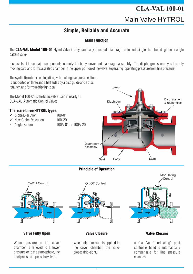
Valve Fully Open
When pressure in the cover
chamber is relieved to a lower
pressure or to the atmosphere, the
inlet pressure opens the valve.
Valve Closure
When inlet pressure is applied to
the cover chamber, the valve
closes drip-tight.
Valve Closure
A Cla -Val “modulating” pilot
control is fitted to automatically
compensate for line pressure
changes.
Main Function
CLA-VAL Model 100-01
There are three HYTROL types:
The Hytrol Valve is a hydraulically operated, diaphragm actuated, single chambered globe or angle
pattern valve.
It consists of three major components, namely: the body, cover and diaphragm assembly. The diaphragm assembly is the only
moving part, and forms a sealed chamber in the upper portion of the valve, separating operating pressure from line pressure.
The synthetic rubber sealing disc, with rectangular cross section,
is supported on three and a half sides by a disc guide and a disc
retainer, and forms a drip tight seal.
The Model 100-01 is the basic valve used in nearly all
CLA-VAL Automatic Control Valves.
Globe Execution 100-01
New Globe Execution 100-20
Angle Pattern 100A-01 or 100A-20
�
�
�
1
Principle of Operation
CLA-VAL 100-01
Main Valve HYTROL
Simple, Reliable and AccurateSimple, Reliable and Accurate
On/Off Control On/Off Control
ModulatingControl
Diaphragmassembly
BodySeat Stem
Diaphragm
Cover
Disc retainer& rubber disc
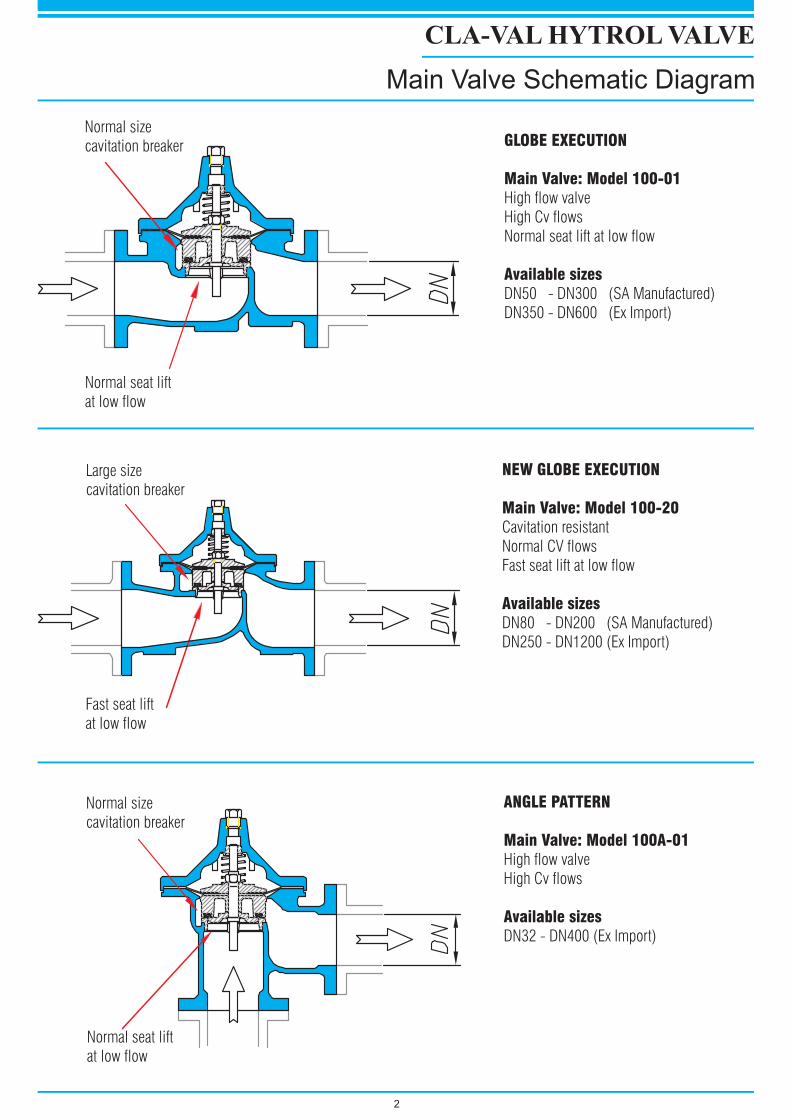
NEW GLOBE EXECUTION
Main Valve: Model 100-20
Available sizes
Cavitation resistant
Normal CV flows
Fast seat lift at low flow
DN80 - DN200 (SA Manufactured)
DN250 - DN1200 (Ex Import)
GLOBE EXECUTION
Main Valve: Model 100-01
Available sizes
High flow valve
High Cv flows
Normal seat lift at low flow
DN50 - DN300 (SA Manufactured)
DN350 - DN600 (Ex Import)
ANGLE PATTERN
Main Valve: Model 100A-01
Available sizes
High flow valve
High Cv flows
DN32 - DN400 (Ex Import)
2
CLA-VAL HYTROL VALVE
Main Valve Schematic Diagram
Large size
cavitation breaker
Fast seat lift
at low flow
Normal size
cavitation breaker
Normal seat lift
at low flow
Normal size
cavitation breaker
Normal seat lift
at low flow
0
10
20
30
40
50
60
70
80
90
100
0 10 20 30 40 50 60 70 80 90 100
% Cv (flow coefficient)
%L
ift
(ste
mlif
t)
g
vH =
CvQ = �p
�p
�pKvQ =
2
2
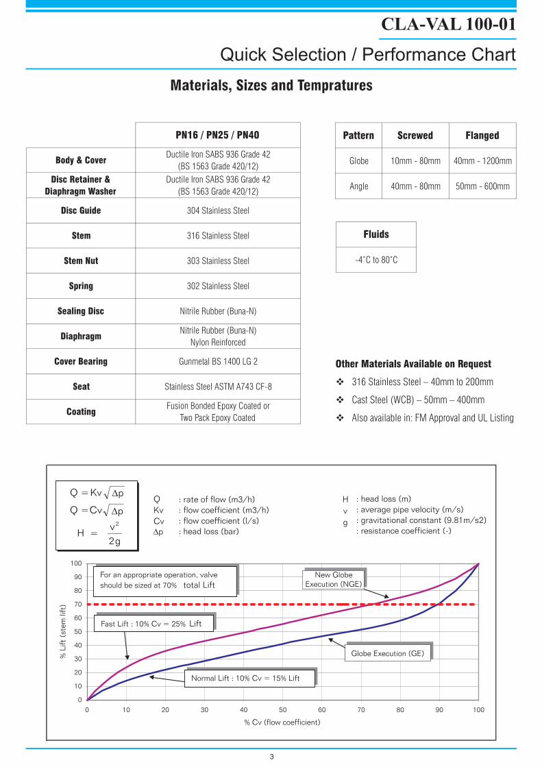
H
v
g
: head loss (m)
: average pipe velocity (m/s)
: gravitational constant (9.81m/s2)
: resistance coefficient (-)
Q
Kv
Cv
: rate of flow (m3/h)
: flow coefficient (m3/h)
: flow coefficient (l/s)
: head loss (bar)
Fast Lift : 10% Cv = 25% Lift
Normal Lift : 10% Cv = 15% Lift
For an appropriate operation, valve
should be sized at 70% total Lift
New Globe
Execution (NGE)
Globe Execution (GE)
CLA-VAL 100-01
Quick Selection / Performance Chart
3
Materials, Sizes and TempraturesMaterials, Sizes and Tempratures
PN16 / PN25 / PN40
Body & CoverDuctile Iron SABS 936 Grade 42
(BS 1563 Grade 420/12)
Disc Retainer &
Diaphragm Washer
Ductile Iron SABS 936 Grade 42
(BS 1563 Grade 420/12)
Disc Guide 304 Stainless Steel
Stem 316 Stainless Steel
Stem Nut 303 Stainless Steel
Spring 302 Stainless Steel
Sealing Disc Nitrile Rubber (Buna-N)
DiaphragmNitrile Rubber (Buna-N)
Nylon Reinforced
Cover Bearing Gunmetal BS 1400 LG 2
Seat Stainless Steel ASTM A743 CF-8
CoatingFusion Bonded Epoxy Coated or
Two Pack Epoxy Coated
Pattern Screwed Flanged
Globe 10mm - 80mm 40mm - 1200mm
Angle 40mm - 80mm 50mm - 600mm
Fluids
-4˚C to 80˚C
Other Materials Available on Request
� 316 Stainless Steel – 40mm to 200mm
� Cast Steel (WCB) – 50mm – 400mm
� Also available in: FM Approval and UL Listing

Nut
Washer
Cover
Cover bearing
Spring
Stem nut
Diaphragm washer
Diaphragm
Disc retainer
Space washer
Disc
Disc guide
Stem
Seat screws
Seat
Seat
Stud
O-ringSeat O-ring
Body
Body
Part Listing for NGE & GE
CLA-VAL HYTROL VALVE
4
GE : DN400NGE : DN500 - DN600
GE : DN200 - DN400NGE : DN250 - DN600
Cover
Coverbearing
assembly
L
ØF
Hm
BA
H1
H
Ø C
Approx. outer limits of pilot-system
Stem
Approximate Weight
Complete Valve : 100%
= 20%
= 20%
= 60%
Cover
Trim
Body
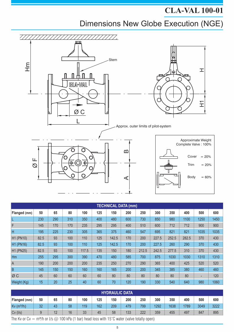
CLA-VAL 100-01
Dimensions New Globe Execution (NGE)
5
The Kv or Cv = m /h or l/s @ 100 kPa (1 bar) head loss with 15 C water (valve totally open)³ ˚
Flanged (mm) 50 65 80 100 125 150 200 250 300 350 400 500 600
L 230 290 310 350 400 480 600 730 850 980 1100 1250 1450
F 145 170 170 235 295 295 400 510 600 712 712 900 900
H 195 225 230 305 365 375 460 547 695 821 821 1035 1035
H1 (PN10) 82.5 93 100 110 125 142.5 170 200 227.5 252.5 282.5 370 430
H1 (PN16) 82.5 93 100 110 125 142.5 170 200 227.5 260 290 370 430
H1 (PN25) 82.5 93 100 117.5 135 150 180 212.5 242.5 277.5 310 370 430
Hm 255 295 300 390 470 480 585 700 875 1030 1030 1310 1310
A 190 200 200 200 235 250 270 290 365 400 425 520 520
B 145 150 150 160 160 165 200 200 345 385 380 460 460
Ø C 45 60 60 60 60 80 80 80 80 80 80 - 120
Weight (Kg) 15 20 25 40 60 70 120 190 330 540 640 980 1060
Flanged (mm) 50 65 80 100 125 150 200 250 300 350 400 500 600
Kv (m³/h) 32 43 58 119 162 209 479 799 1292 1638 1789 3049 3222
Cv (l/s) 9 12 16 33 45 58 133 222 359 455 497 847 895
TECHNICAL DATA (mm)
HYDRAULIC DATA

L
ØF
Hm
BA
L1
HH
1
H2
DN 40 - DN 200DN 250 - DN 400
Rp 1 1/2" - 3"
LScrewed pattern
Ø C
L1Rp 1 1/4"
Stem
Approx. outer limits of pilot-system
Approximate Weight
Complete Valve : 100%
= 20%
= 20%
= 60%
Cover
Trim
Body
CLA-VAL 100-01
Dimensions New Globe Execution (GE)
6
The Kv or Cv = m /h or l/s @ 100 kPa (1 bar) head loss with 15 C water (valve totally open)³ ˚
Flanged (mm)
Screwed (in)
32
1¼"
40
1½"
50
2"
65
2½"
80
3"
100
-
150
-
200
-
250
-
300
-
400
-
L 215 215 254 280 305 381 508 645 756 864 1051
L1 200 184.5 238 280 318 - - - - - -
F 145 145 170 205 235 295 400 510 600 712 900
H 191 191 215 245 260 345 415 495 595 695 850
H1 (PN10 - 16) - 75 82.5 93 100 110 142.5 170 - - -
H1 (PN25) - 75 82.5 93 100 117.5 150 180 - - -
H2 - - - - - - - 236 274 395
Hm 252 252 285 320 345 450 540 645 780 905 1120
A 150 150 150 165 203 216 230 285 330 370 475
B 100 100 100 115 127 152 205 260 305 362 450
Ø C - - 47 60 60 82 82 82 82 - -
Weight (Kg) 13 13 20 25 30 50 95 170 310 470 970
Flanged (mm)
Screwed (in)
32
1¼"
40
1½"
50
2"
65
2½"
80
3"
100
-
150
-
200
-
250
-
300
-
400
-
Kv (m³/h) 26 28 47 72 101 173 400 666 1076 1490 2542
Cv (l/s) 7 8 13 20 28 48 111 185 299 414 706
TECHNICAL DATA (mm)
HYDRAULIC DATA
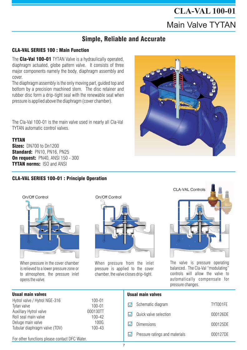
CLA-VAL 100-01
Main Valve TYTAN
Simple, Reliable and AccurateSimple, Reliable and Accurate
7
The TYTAN Valve is a hydraulically operated,
diaphragm actuated, globe pattern valve. It consists of three
major components namely the body, diaphragm assembly and
cover.
The diaphragm assembly is the only moving part, guided top and
bottom by a precision machined stem. The disc retainer and
rubber disc form a drip-tight seal with the renewable seat when
pressure is applied above the diaphragm (cover chamber).
Cla-Val 100-01
CLA-VAL SERIES 100 : Main Function
CLA-VAL SERIES 100-01 : Principle Operation
The Cla-Val 100-01 is the main valve used in nearly all Cla-Val
TYTAN automatic control valves.
DN700 to Dn1200
PN10, PN16, PN25
PN40, ANSI 150 - 300
ISO and ANSI
TYTANSizes:Standard:On request:TYTAN norms:
When pressure in the cover chamber
is relieved to a lower pressure zone or
to atmosphere, the pressure inlet
opens the valve.
The valve is pressure operating
balanced. The Cla-Val “modulating”
controls will allow the valve to
automatically compensate for
pressure changes.
When pressure from the inlet
pressure is applied to the cover
chamber, the valve closes drip-tight.
Hytrol valve / Hytrol NGE-316 100-01
Tytan valve 100-01
Auxillary Hytrol valve 000130TT
Roll seal main valve 100-42
Deluge main valve 100G
Tubular diaphragm valve (TDV) 100-43
For other functions please contact DFC Water.
Usual main valves Usual main valves
Schematic diagram TYT001FE
Quick valve selection 000126DE
Dimensions 000125DE
Pressure ratings and materials 000127DE
00121DE
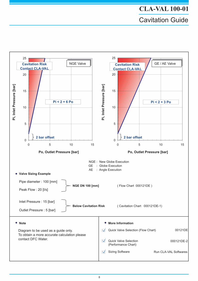
NGE : New Globe Execution
GE : Globe Execution
AE : Angle Execution
Valve Sizing Example
NGE DN 100 [mm]
Pipe diameter : 100 [mm]( Flow Chart 000121DE )
Peak Flow : 20 [l/s]
Inlet Pressure : 15 [bar]
Below Cavitation Risk ( Cavitation Chart 000121DE-1)
Outlet Pressure : 5 [bar]
Note More Information
Quick Valve Selection (Flow Chart)
Quick Valve Selection(Performance Chart)
Sizing Software
000121DE-2
Run CLA-VAL Softwares
Diagram to be used as a guide only.
To obtain a more accurate calculation please
contact DFC Water.
0
5
10
15
20
25
0 5 10 15
Pi,
Inle
tP
ressu
re[b
ar]
NGE Valve
Po, Outlet Pressure [bar]
Pi < 2 + 6 Po
Cavitation Risk
Contact CLA-VAL
2 bar offset0
5
10
15
20
25
0 5 10 15
Pi,
Inle
tP
ressu
re[b
ar]
Cavitation Risk
Contact CLA-VAL
Po, Outlet Pressure [bar]
GE / AE Valve
Pi < 2 + 3 Po
2 bar offset
CLA-VAL 100-01
Cavitation Guide
8
9
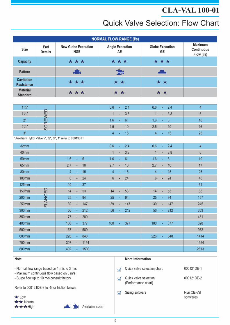
CLA-VAL 100-01
Quick Valve Selection: Flow Chart
SizeEnd
Details
Maximum
Continuous
Flow (l/s)
Capacity
Pattern
Cavitation
Resistance
Material
Standard
1¼" 0.6 - 2.4 0.6 - 2.4 4
1½" 1 - 3.8 1 - 3.8 6
2" 1.6 - 6 1.6 - 6 10
2½" 2.5 - 10 2.5 - 10 16
3" 4 - 15 4 - 15 25
* Auxilliary Hytrol Valve ?", ½", ¾", 1" refer to 000130TT
32mm 0.6 - 2.4 0.6 - 2.4 4
40mm 1 - 3.8 1 - 3.8 6
50mm 1.6 - 6 1.6 - 6 1.6 - 6 10
65mm 2.7 - 10 2.7 - 10 2.7 - 10 17
80mm 4 - 15 4 - 15 4 - 15 25
100mm 6 - 24 6 - 24 6 - 24 40
125mm 10 - 37 61
150mm 14 - 53 14 - 53 14 - 53 88
200mm 25 - 94 25 - 94 25 - 94 157
250mm 39 - 147 39 - 147 39 - 147 245
300mm 56 - 212 56 - 212 56 - 212 353
350mm 77 - 289 481
400mm 100 - 377 100 - 377 100 - 377 628
500mm 157 - 589 982
600mm 226 - 848 226 - 848 1414
700mm 307 - 1154 1924
800mm 402 - 1508 2513
Note More Information
- Normal flow range based on 1 m/s to 3 m/s Quick valve selection chart 000121DE-1
- Maximum continuous flow based on 5 m/s
- Surge flow up to 10 m/s consult factory Quick valve selection 000121DE-2
(Performance chart)
Refer to 000121DE-3 to -5 for friction losses
Sizing software Run Cla-Val
Low softwares
Normal
High Available sizes
NORMAL FLOW RANGE (l/s)
New Globe Execution
NGE
Angle Execution
AE
Globe Execution
GE
SC
RE
WE
DF
LA
NG
ED
Usual SERIES 40/640 : Combinations
Main Valve 100-01/100-20
Rate of Flow Control 40-01/640-01
“ + Float Control 46-01/646-01
“ + Check valve 41-01/641-01
“ + Solenoid on/off 43-01/643-01
“ + Pressure sustaining 45-01/645-01
“ + Pressure reducing 49-01/649-01
For other functions please contact DFC Water.
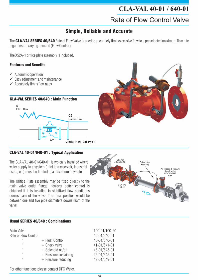
The Rate of Flow Valve is used to accurately limit excessive flow to a preselected maximum flow rate
regardless of varying demand (Flow Control).
The X52A-1 orifice plate assembly is included.
Automatic operation
Easy adjustment and maintenance
Accurately limits flow rates
CLA-VAL SERIES 40/640
Features and Benefits
�
�
�
CLA-VAL 40-01/640-01 : Typical Application
The CLA-VAL 40-01/640-01 is typically installed where
water supply to a system (inlet to a reservoir, industrial
users, etc) must be limited to a maximum flow rate.
The Orifice Plate assembly may be fixed directly to the
main valve outlet flange, however better control is
obtained if it is installed in stabilized flow conditions
downstream of the valve. The ideal position would be
between one and five pipe diameters downstream of the
valve.
CLA-VAL SERIES 40/640 : Main Function
10
CLA-VAL 40-01 / 640-01
Rate of Flow Control Valve
Simple, Reliable and AccurateSimple, Reliable and Accurate
Orifice plateassembly
Air release & vacuumbreak valve
VENT-O-MATRBX
StrainerAQUA 90-501
CLA-VAL40-01
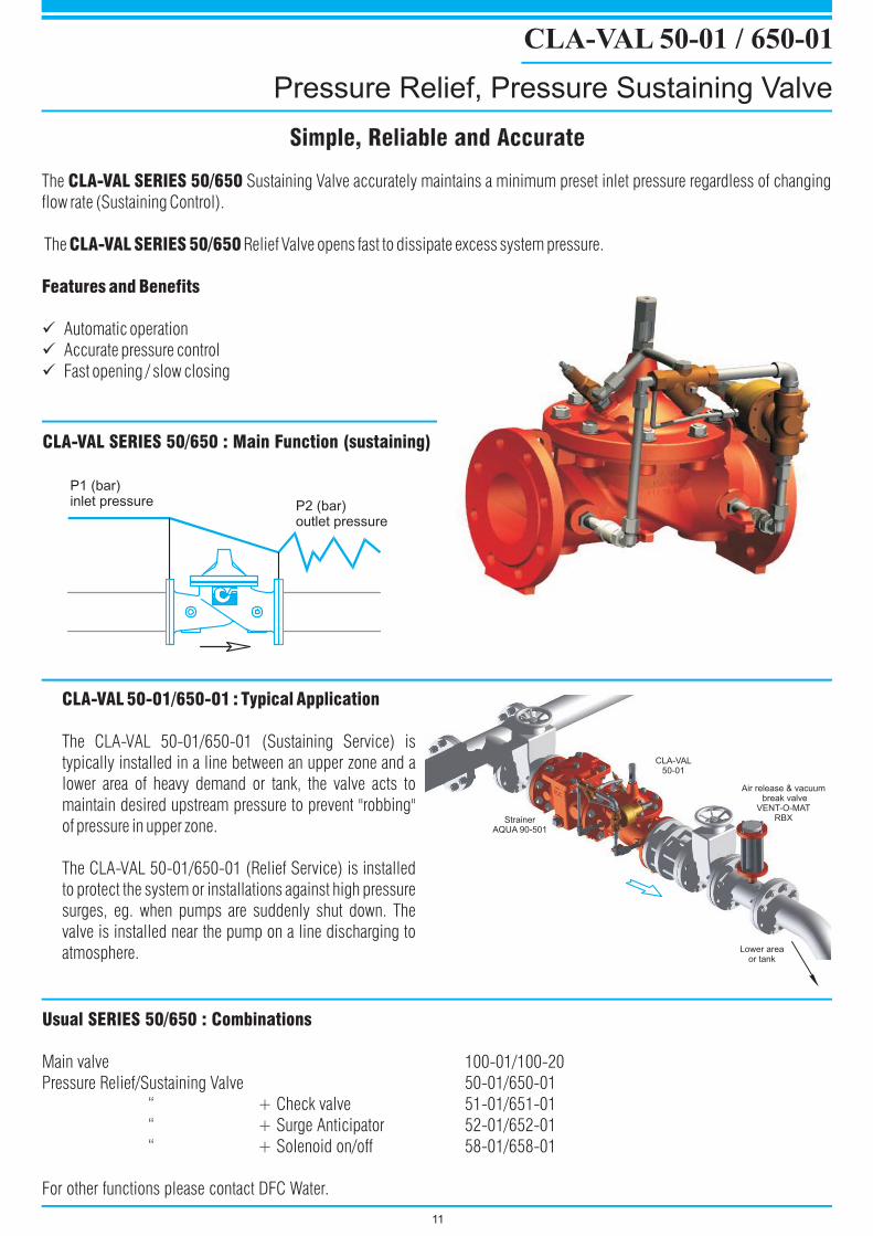
The Sustaining Valve accurately maintains a minimum preset inlet pressure regardless of changing
flow rate (Sustaining Control).
The Relief Valve opens fast to dissipate excess system pressure.
Automatic operation
Accurate pressure control
Fast opening / slow closing
CLA-VAL SERIES 50/650
CLA-VAL SERIES 50/650
Features and Benefits
�
�
�
CLA-VAL 50-01/650-01 : Typical Application
The CLA-VAL 50-01/650-01 (Sustaining Service) is
typically installed in a line between an upper zone and a
lower area of heavy demand or tank, the valve acts to
maintain desired upstream pressure to prevent "robbing"
of pressure in upper zone.
The CLA-VAL 50-01/650-01 (Relief Service) is installed
to protect the system or installations against high pressure
surges, eg. when pumps are suddenly shut down. The
valve is installed near the pump on a line discharging to
atmosphere.
Usual SERIES 50/650 : Combinations
Main valve 100-01/100-20
Pressure Relief/Sustaining Valve 50-01/650-01
“ + Check valve 51-01/651-01
“ + Surge Anticipator 52-01/652-01
“ + Solenoid on/off 58-01/658-01
For other functions please contact DFC Water.
CLA-VAL SERIES 50/650 : Main Function (sustaining)
P1 (bar)inlet pressure P2 (bar)
outlet pressure
11
CLA-VAL 50-01 / 650-01
Pressure Relief, Pressure Sustaining Valve
Simple, Reliable and AccurateSimple, Reliable and Accurate
Lower areaor tank
StrainerAQUA 90-501
CLA-VAL50-01
Air release & vacuumbreak valve
VENT-O-MATRBX
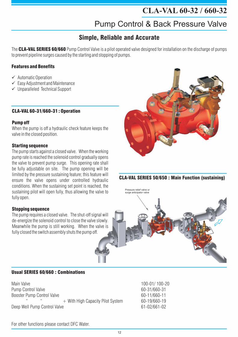
The Pump Control Valve is a pilot operated valve designed for installation on the discharge of pumps
to prevent pipeline surges caused by the starting and stopping of pumps.
Automatic Operation
Easy Adjustment and Maintenance
Unparalleled Technical Support
CLA-VAL SERIES 60/660
Features and Benefits
�
�
�
CLA-VAL 60-31/660-31 : Operation
Pump off
Starting sequence
Stopping sequence
When the pump is off a hydraulic check feature keeps the
valve in the closed position.
The pump starts against a closed valve. When the working
pump rate is reached the solenoid control gradually opens
the valve to prevent pump surge. This opening rate shall
be fully adjustable on site. The pump opening will be
limited by the pressure sustaining feature; this feature will
ensure the valve opens under controlled hydraulic
conditions. When the sustaining set point is reached, the
sustaining pilot will open fully, thus allowing the valve to
fully open.
The pump requires a closed valve. The shut-off signal will
de-energize the solenoid control to close the valve slowly.
Meanwhile the pump is still working. When the valve is
fully closed the switch assembly shuts the pump off.
Usual SERIES 60/660 : Combinations
Main Valve 100-01/ 100-20
Pump Control Valve 60-31/660-31
Booster Pump Control Valve 60-11/660-11
“ “ + With High Capacity Pilot System 60-19/660-19
Deep Well Pump Control Valve 61-02/661-02
For other functions please contact DFC Water.
CLA-VAL 60-32 / 660-32
Pump Control & Back Pressure Valve
Simple, Reliable and AccurateSimple, Reliable and Accurate
12
CLA-VAL SERIES 50/650 : Main Function (sustaining)
Pressure relief valve orsurge anticipator valve
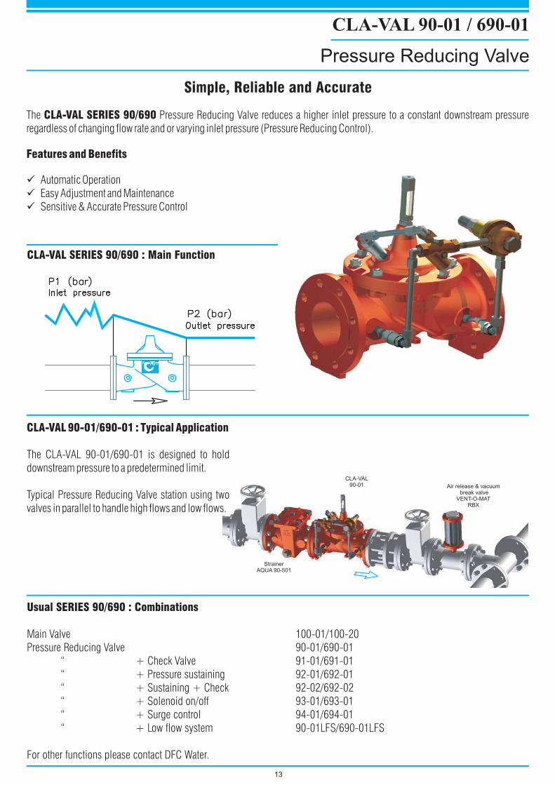
The Pressure Reducing Valve reduces a higher inlet pressure to a constant downstream pressure
regardless of changing flow rate and or varying inlet pressure (Pressure Reducing Control).
Automatic Operation
Easy Adjustment and Maintenance
Sensitive & Accurate Pressure Control
CLA-VAL SERIES 90/690
Features and Benefits
�
�
�
CLA-VAL 90-01/690-01 : Typical Application
The CLA-VAL 90-01/690-01 is designed to hold
downstream pressure to a predetermined limit.
Typical Pressure Reducing Valve station using two
valves in parallel to handle high flows and low flows.
Usual SERIES 90/690 : Combinations
Main Valve 100-01/100-20
Pressure Reducing Valve 90-01/690-01
“ + Check Valve 91-01/691-01
“ + Pressure sustaining 92-01/692-01
“ + Sustaining + Check 92-02/692-02
“ + Solenoid on/off 93-01/693-01
“ + Surge control 94-01/694-01
“ + Low flow system 90-01LFS/690-01LFS
For other functions please contact DFC Water.
CLA-VAL SERIES 90/690 : Main Function
13
CLA-VAL 90-01 / 690-01
Pressure Reducing Valve
Simple, Reliable and AccurateSimple, Reliable and Accurate
Air release & vacuumbreak valve
VENT-O-MATRBX
CLA-VAL90-01
StrainerAQUA 90-501
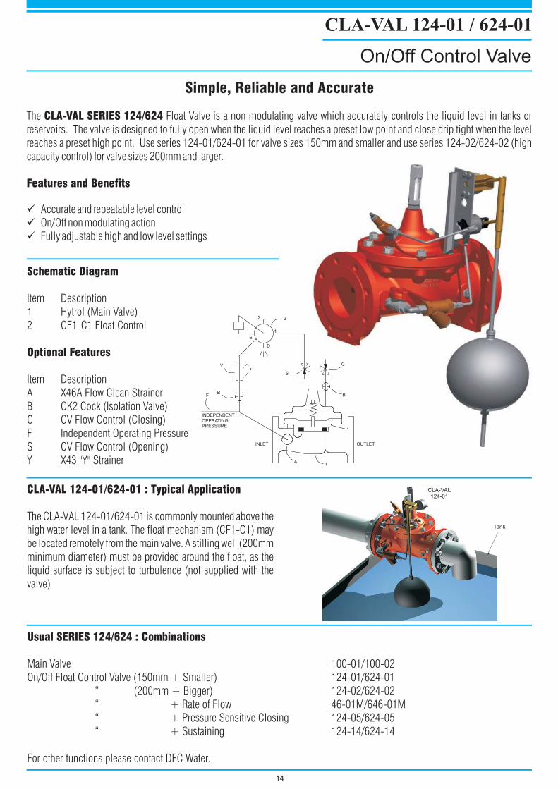
The Float Valve is a non modulating valve which accurately controls the liquid level in tanks or
reservoirs. The valve is designed to fully open when the liquid level reaches a preset low point and close drip tight when the level
reaches a preset high point. Use series 124-01/624-01 for valve sizes 150mm and smaller and use series 124-02/624-02 (high
capacity control) for valve sizes 200mm and larger.
Accurate and repeatable level control
On/Off non modulating action
Fully adjustable high and low level settings
CLA-VAL SERIES 124/624
Features and Benefits
�
�
�
CLA-VAL 124-01 : Typical Application/624-01
The CLA-VAL 124-01/624-01 is commonly mounted above the
high water level in a tank. The float mechanism (CF1-C1) may
be located remotely from the main valve. A stilling well (200mm
minimum diameter) must be provided around the float, as the
liquid surface is subject to turbulence (not supplied with the
valve)
Usual SERIES 124/624 : Combinations
Main Valve 100-01/100-02
On/Off Float Control Valve (150mm + Smaller) 124-01/624-01
“ (200mm + Bigger) 124-02/624-02
For other functions please contact DFC Water.
“ + Rate of Flow 46-01M/646-01M
“ + Pressure Sensitive Closing 124-05/624-05
“ + Sustaining 124-14/624-14
22
S
D
Y
BF
A1
C
B
1
INLET OUTLET
INDEPENDENTOPERATINGPRESSURE
S
CLA-VAL 124-01 / 624-01
On/Off Control Valve
Simple, Reliable and AccurateSimple, Reliable and Accurate
14
Schematic Diagram
Optional Features
Item Description
1 Hytrol (Main Valve)
2 CF1-C1 Float Control
Item Description
A X46A Flow Clean Strainer
B CK2 Cock (Isolation Valve)
C CV Flow Control (Closing)
F Independent Operating Pressure
S CV Flow Control (Opening)
Y X43 "Y" Strainer
Tank
CLA-VAL124-01
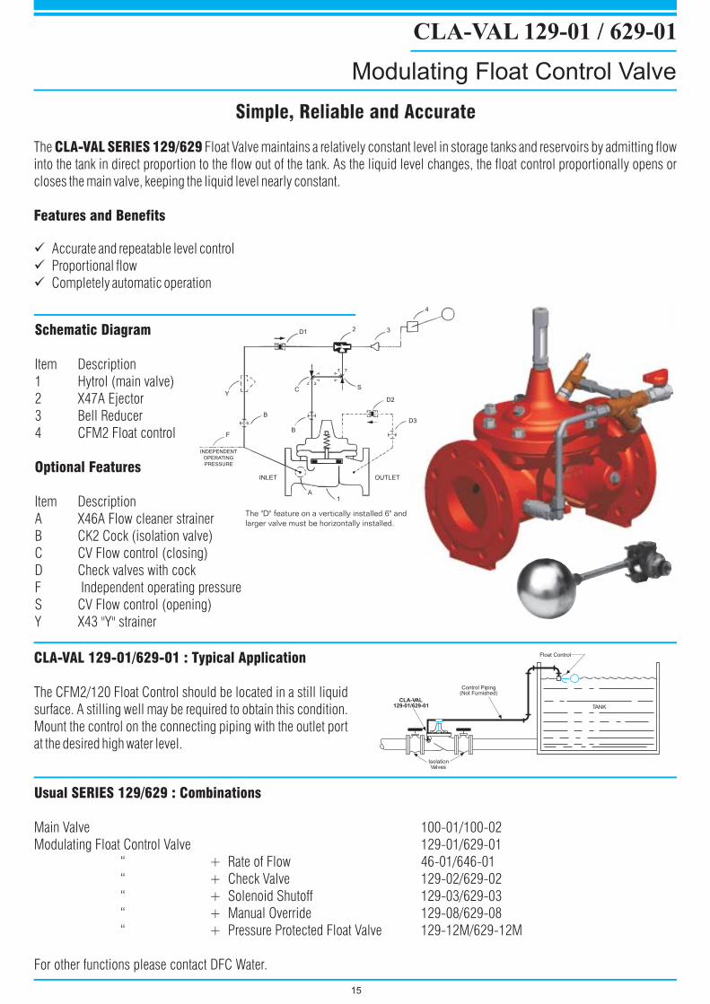
The Float Valve maintains a relatively constant level in storage tanks and reservoirs by admitting flow
into the tank in direct proportion to the flow out of the tank. As the liquid level changes, the float control proportionally opens or
closes the main valve, keeping the liquid level nearly constant.
Accurate and repeatable level control
Proportional flow
Completely automatic operation
CLA-VAL SERIES 129/629
Features and Benefits
�
�
�
CLA-VAL : Typical Application129-01/629-01
The CFM2/120 Float Control should be located in a still liquid
surface. A stilling well may be required to obtain this condition.
Mount the control on the connecting piping with the outlet port
at the desired high water level.
Usual SERIES 129/629 : Combinations
Main Valve 100-01/100-02
Modulating Float Control Valve 129-01/629-01
“ + Manual Override 129-08/629-08
“ + Pressure Protected Float Valve 129-12M/629-12M
For other functions please contact DFC Water.
“ + Rate of Flow 46-01/646-01
“ + Check Valve 129-02/629-02
“ + Solenoid Shutoff 129-03/629-03
4
32D1
Y
B
F
INLET OUTLET
A1
D3
D2
C
B
S
INDEPENDENT
OPERATING
PRESSURE
The "D" feature on a vertically installed 6" and
larger valve must be horizontally installed.
IsolationValves
TANK
CLA-VAL129-01/629-01
Control Piping(Not Furnished)
Float Control
CLA-VAL 129-01 / 629-01
Modulating Float Control Valve
Simple, Reliable and AccurateSimple, Reliable and Accurate
Schematic Diagram
Optional Features
Item Description
1 Hytrol (main valve)
2 X47A Ejector
3 Bell Reducer
4 CFM2 Float control
Item Description
A X46A Flow cleaner strainer
B CK2 Cock (isolation valve)
C CV Flow control (closing)
D Check valves with cock
F Independent operating pressure
S CV Flow control (opening)
Y X43 "Y" strainer
15
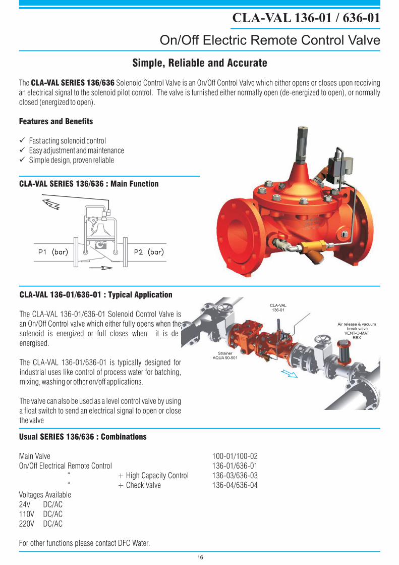
The Solenoid Control Valve is an On/Off Control Valve which either opens or closes upon receiving
an electrical signal to the solenoid pilot control.
Fast acting solenoid control
Easy adjustment and maintenance
Simple design, proven reliable
CLA-VAL SERIES 136/636
Features and Benefits
The valve is furnished either normally open (de-energized to open), or normally
closed (energized to open).
�
�
�
CLA-VAL : Typical Application136-01/636-01
The CLA-VAL 136-01/636-01 Solenoid Control Valve is
an On/Off Control valve which either fully opens when the
solenoid is energized or full closes when it is de-
energised.
The CLA-VAL 136-01/636-01 is typically designed for
industrial uses like control of process water for batching,
mixing, washing or other on/off applications.
The valve can also be used as a level control valve by using
a float switch to send an electrical signal to open or close
the valve
Usual SERIES 136/636 : Combinations
Main Valve 100-01/100-02
On/Off Electrical Remote Control 136-01/636-01
Voltages Available
220V DC/AC
For other functions please contact DFC Water.
“ + High Capacity Control 136-03/636-03
“ + Check Valve 136-04/636-04
24V DC/AC
110V DC/AC
CLA-VAL SERIES 136/636 : Main Function
16
CLA-VAL 136-01 / 636-01
On/Off Electric Remote Control Valve
Simple, Reliable and AccurateSimple, Reliable and Accurate
Air release & vacuumbreak valve
VENT-O-MATRBX
StrainerAQUA 90-501
CLA-VAL136-01
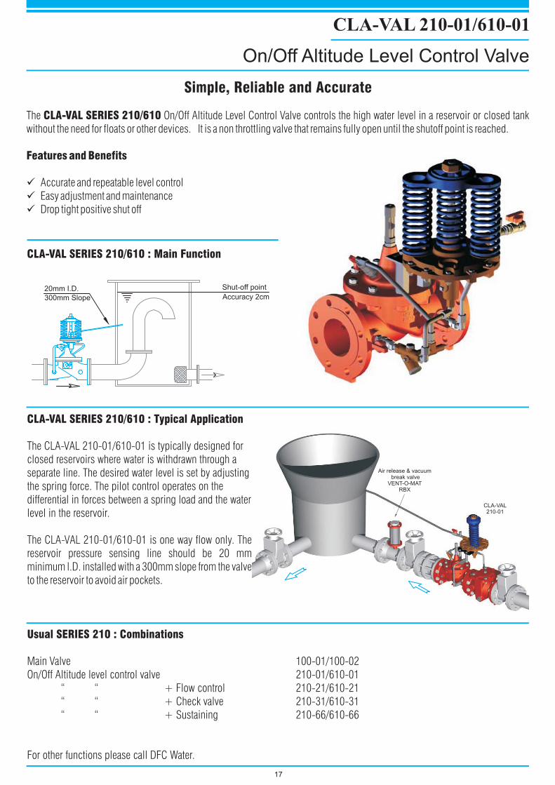
The On/Off Altitude Level Control Valve controls the high water level in a reservoir or closed tank
without the need for floats or other devices. It is a non throttling valve that remains fully open until the shutoff point is reached.
Accurate and repeatable level control
Easy adjustment and maintenance
Drop tight positive shut off
CLA-VAL SERIES 210/610
Features and Benefits
�
�
�
CLA-VAL SERIES 210/610 : Typical Application
The CLA-VAL 210-01/610-01 is typically designed for
closed reservoirs where water is withdrawn through a
separate line. The desired water level is set by adjusting
the spring force. The pilot control operates on the
differential in forces between a spring load and the water
level in the reservoir.
The CLA-VAL 210-01/610-01 is one way flow only. The
reservoir pressure sensing line should be 20 mm
minimum l.D. installed with a 300mm slope from the valve
to the reservoir to avoid air pockets.
CLA-VAL SERIES 210/610 : Main Function
300mm Slope
20mm I.D. Shut-off point
Accuracy 2cm
CLA-VAL 210-01/610-01
On/Off Altitude Level Control Valve
Simple, Reliable and AccurateSimple, Reliable and Accurate
17
Usual SERIES 210 : Combinations
Main Valve 100-01/100-02
On/Off Altitude level control valve 210-01/610-01
“ “ + Flow control 210-21/610-21
“ “ + Check valve 210-31/610-31
“ “ + Sustaining 210-66/610-66
For other functions please call DFC Water.
CLA-VAL210-01
Air release & vacuumbreak valve
VENT-O-MATRBX
Outlet
Outlet
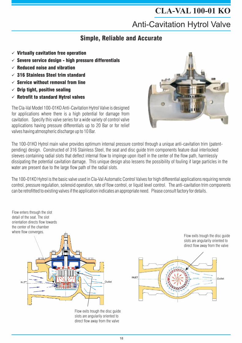
CLA-VAL 100-01 KO
Anti-Cavitation Hytrol Valve
18
�
�
�
�
�
�
�
Virtually cavitation free operation
Severe service design - high pressure differentials
Reduced noise and vibration
316 Stainless Steel trim standard
Service without removal from line
Drip tight, positive sealing
Retrofit to standard Hytrol valves
The 100-01KO Hytrol main valve provides optimum internal pressure control through a unique anti-cavitation trim (patent-
pending) design. Constructed of 316 Stainless Steel, the seat and disc guide trim components feature dual interlocked
sleeves containing radial slots that deflect internal flow to impinge upon itself in the center of the flow path, harmlessly
dissipating the potential cavitation damage. This unique design also lessens the possibility of fouling if large particles in the
water are present due to the large flow path of the radial slots.
The 100-01KO Hytrol is the basic valve used in Cla-Val Automatic Control Valves for high differential applications requiring remote
control, pressure regulation, solenoid operation, rate of flow control, or liquid level control. The anti-cavitation trim components
can be retrofitted to existing valves if the application indicates an appropriate need. Please consult factory for details.
Simple, Reliable and AccurateSimple, Reliable and Accurate
Flow exits trough the disc guide
slots are angularily oriented to
direct flow away from the valve
Flow exits trough the disc guide
slots are angularily oriented to
direct flow away from the valve
Flow enters through the slot
detail of the seat. The slot
orientation directs flow towards
the center of the chamber
where flow converges.
The Cla-Val Model 100-01KO Anti-Cavitation Hytrol Valve is designed
for applications where there is a high potential for damage from
cavitation. Specify this valve series for a wide variety of control valve
applications having pressure differentials up to 20 Bar or for relief
valves having atmospheric discharge up to 10 Bar.
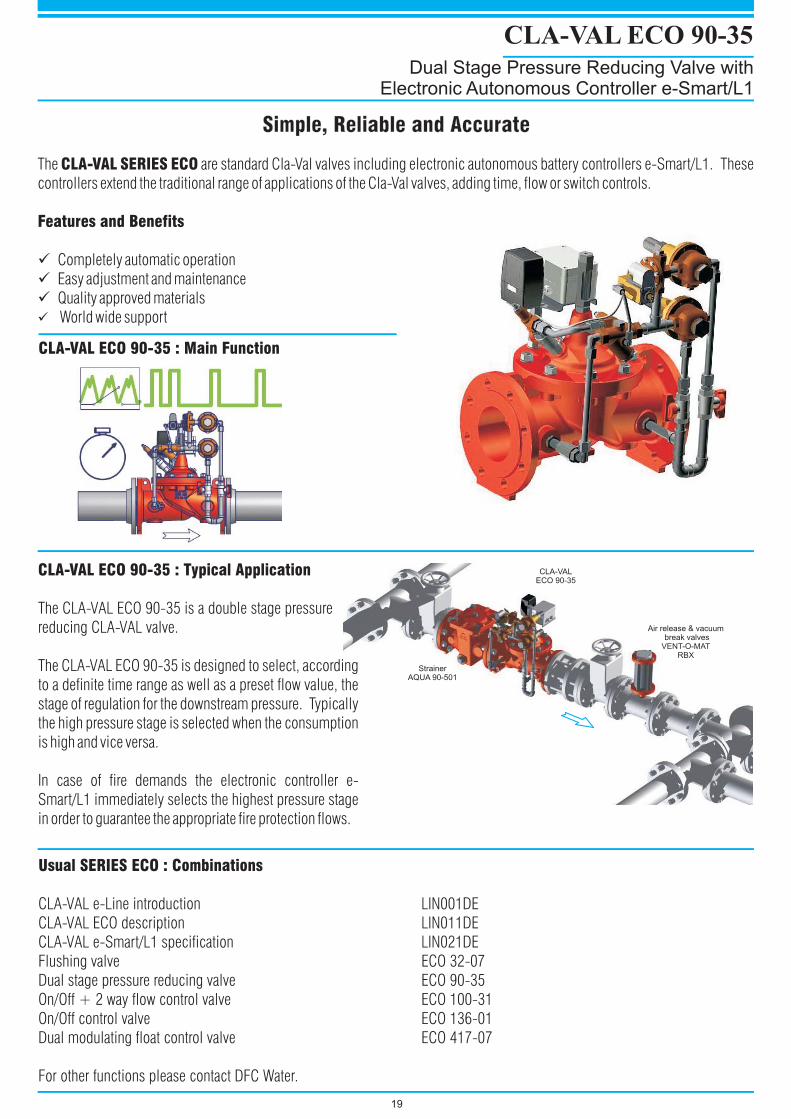
CLA-VAL ECO 90-35
Dual Stage Pressure Reducing Valve withElectronic Autonomous Controller e-Smart/L1
19
Simple, Reliable and AccurateSimple, Reliable and Accurate
CLA-VAL ECO 90-35 : Main Function
CLA-VAL ECO 90-35 : Typical Application
The CLA-VAL ECO 90-35 is a double stage pressure
reducing CLA-VAL valve.
The CLA-VAL ECO 90-35 is designed to select, according
to a definite time range as well as a preset flow value, the
stage of regulation for the downstream pressure. Typically
the high pressure stage is selected when the consumption
is high and vice versa.
In case of fire demands the electronic controller e-
Smart/L1 immediately selects the highest pressure stage
in order to guarantee the appropriate fire protection flows.
The are standard Cla-Val valves including electronic autonomous battery controllers e-Smart/L1. These
controllers extend the traditional range of applications of the Cla-Val valves, adding time, flow or switch controls.
Completely automatic operation
Easy adjustment and maintenance
Quality approved materials
World wide support
CLA-VAL SERIES ECO
Features and Benefits
�
�
�
�
Usual SERIES ECO : Combinations
CLA-VAL e-Line introduction LIN001DE
CLA-VAL ECO description LIN011DE
CLA-VAL e-Smart/L1 specification LIN021DE
Flushing valve ECO 32-07
Dual stage pressure reducing valve ECO 90-35
On/Off + 2 way flow control valve ECO 100-31
On/Off control valve ECO 136-01
Dual modulating float control valve ECO 417-07
For other functions please contact DFC Water.
StrainerAQUA 90-501
CLA-VALECO 90-35
Air release & vacuumbreak valves
VENT-O-MATRBX
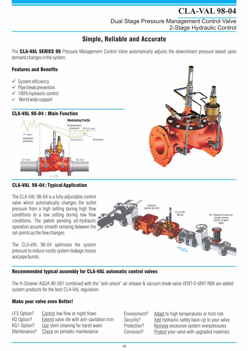
CLA-VAL 98-04
Dual Stage Pressure Management Control Valve2-Stage Hydraulic Control
20
CLA-VAL 98-04 : Typical Application
The CLA-VAL 98-04 is a fully adjustable control
valve which automatically changes the outlet
pressure from a high setting during high flow
conditions to a low setting during low flow
conditions. The patent pending all-hydraulic
operation assures smooth ramping between the
set-points as the flow changes.
The CLA-VAL 98-04 optimizes the system
pressure to reduce costly system leakage losses
and pipe bursts.
Simple, Reliable and AccurateSimple, Reliable and Accurate
The Pressure Management Control Valve automatically adjusts the downstream pressure based upon
demand changes in the system.
System efficiency
Pipe break prevention
100% hydraulic control
World wide support
CLA-VAL SERIES 98
Features and Benefits
�
�
�
�
Recommended typical assembly for CLA-VAL automatic control valves
Make your valve even Better!
The H-Strainer AQUA 90-501 combined with the “anti-shock” air release & vacuum break valve VENT-O-MAT RBX are added
system products for the best CLA-VAL regulation.
LFS Option? low flow or night flows
KO Option? valve life with anti-cavitation trim
KG1 Option? stem cleaning for harsh water
Maintenance? on periodic maintenance
Control
Extend
Use
Check
Downstreampressure
Economy
StrainerAQUA 90-501
CLA-VAL98-04
Modulating Profile
Upstreampressure
CLA-VAL 98-04 : Main Function
Environment? to high temperatures or frost risk
Security? hydraulic safety back-up to your valve
Protection? excessive system overpressures
Corrosion? your valve with upgraded materials
Adapt
Add
Remove
Protect
Air release & vacuumbreak valves
VENT-O-MATRBX
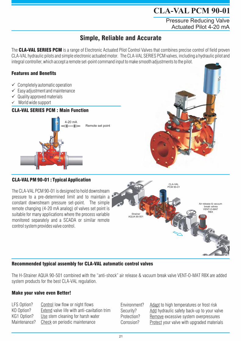
CLA-VAL PCM 90-01
Pressure Reducing ValveActuated Pilot 4-20 mA
21
CLA-VAL PM 90-01 : Typical Application
The CLA-VAL PCM 90-01 is designed to hold downstream
pressure to a pre-determined limit and to maintain a
constant downstream pressure set-point. The simple
remote changing (4-20 mA analog) of valves set point is
suitable for many applications where the process variable
monitored separately and a SCADA or similar remote
control system provides valve control.
Simple, Reliable and AccurateSimple, Reliable and Accurate
The is a range of Electronic Actuated Pilot Control Valves that combines precise control of field proven
CLA-VAL hydraulic pilots and simple electronic actuated motor. The CLA-VAL SERIES PCM valves, including a hydraulic pilot and
integral controller, which accept a remote set-point command input to make smooth adjustments to the pilot.
Completely automatic operation
Easy adjustment and maintenance
Quality approved materials
World wide support
CLA-VAL SERIES PCM
Features and Benefits
�
�
�
�
CLA-VAL SERIES PCM : Main Function
Remote set point4-20 mA
StrainerAQUA 90-501
CLA-VALPCM 90-01
Recommended typical assembly for CLA-VAL automatic control valves
Make your valve even Better!
The H-Strainer AQUA 90-501 combined with the “anti-shock” air release & vacuum break valve VENT-O-MAT RBX are added
system products for the best CLA-VAL regulation.
LFS Option? low flow or night flows
KO Option? valve life with anti-cavitation trim
KG1 Option? stem cleaning for harsh water
Maintenance? on periodic maintenance
Control
Extend
Use
Check
Environment? to high temperatures or frost risk
Security? hydraulic safety back-up to your valve
Protection? excessive system overpressures
Corrosion? your valve with upgraded materials
Adapt
Add
Remove
Protect
Air release & vacuumbreak valves
VENT-O-MATRBX
Usual SERIES 60/660 : Combinations
Main Valve 100 - 42
Pressure Reducing 790 - 01
Pressure Relief 750 - 01
Level Control 724 - 01
PILOTCONTROLVALVE
RESTRICTOR
SEATING AREA
CONTROL CHAMBER
INLET
RESTRICTOR
SEATING AREA
INLET
CONTROL CHAMBER
PILOT
CONTROL
VALVE
RESTRICTOR
SEATING AREA
CONTROL CHAMBER
INLET
PILOT
CONTROL
VALVE
NSF
CLA-VAL 100-42
700 Series Roll Seal
Simple, Reliable and AccurateSimple, Reliable and Accurate
22
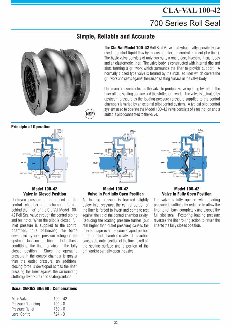
The Roll Seal Valve is a hydraulically operated valve
used to control liquid flow by means of a flexible control element (the liner).
The basic valve consists of only two parts a one piece, investment cast body
and an elastomeric liner. The valve body is constructed with internal ribs and
slots forming a grillwork which surrounds the liner to provide support. A
normally closed type valve is formed by the installed liner which covers the
grillwork and seats against the raised seating surface in the valve body.
Upstream pressure actuates the valve to produce valve opening by rolling the
liner off the seating surface and the slotted grillwork. The valve is actuated by
upstream pressure as the loading pressure (pressure supplied to the control
chamber) is varied by an external pilot control system. A typical pilot control
system used to operate the Model 100-42 valve consists of a restriction and a
suitable pilot connected to the valve.
Cla-Val Model 100-42
Upstream pressure is introduced to the
control chamber (the chamber formed
behind the liner) of the Cla-Val Model 100-
42 Roll Seal valve through the control piping
and restrictor. When the pilot is closed, full
inlet pressure is supplied to the control
chamber, thus balancing the force
developed by inlet pressure acting on the
upstream face on the liner. Under these
conditions, the liner remains in the fully
closed position. Since the operating
pressure in the control chamber is greater
than the outlet pressure, an additional
closing force is developed across the liner,
pressing the liner against the surrounding
slotted grillwork area and seating surface.
As loading pressure is lowered slightly
below inlet pressure, the central portion of
the liner is forced to invert and come to rest
against the tip of the control chamber cavity.
Reducing the loading pressure further (but
still higher than outlet pressure) causes the
liner to drape over the cone shaped portion
of the control chamber cavity. This action
causes the outer section of the liner to roll off
the seating surface and a portion of the
grillwork to partially open the valve.
The valve is fully opened when loading
pressure is sufficiently reduced to allow the
liner to roll back completely and expose the
full slot area. Restoring loading pressure
reverses the liner rolling action to return the
liner to the fully closed position.
Model 100-42Valve in Closed Position
Model 100-42Valve in Partially Open Position
Model 100-42Valve in Fully Open Position
Principle of Operation
CLA-VAL 90-501
H - Strainer
Simple, Reliable and AccurateSimple, Reliable and Accurate
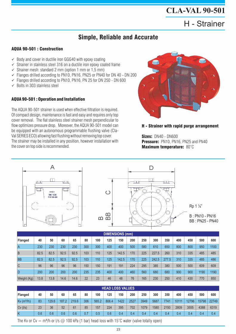
AQUA 90-501 : Operation and Installation
The AQUA 90-501 strainer is used when effective filtration is required.
Of compact design, maintenance is fast and easy and requires only top
cover removal. The flat stainless steel strainer mesh perpendicular to
flow optimizes pressure drop. Moreover, the AQUA 90-501 model can
be equipped with an autonomous programmable flushing valve (Cla-
Val SERIES ECO) allowing fast flushing without removing top cover.
The strainer may be installed in any position, however installation with
the cover on top side is recommended.
H - Strainer with rapid purge arrangement
Sizes:Pressure:Maximum temperature:
DN40 - DN600
PN10, PN16, PN25 and PN40
80 C˚
AQUA 90-501 : Construction
�
�
�
�
�
�
Body and cover in ductile iron GGG40 with epoxy coating
Strainer in stainless steel 316 on a ductile iron epoxy coated frame
Strainer mesh: standard 2 mm (option 1 mm or 1,5 mm)
Flanges drilled according to PN10, PN16, PN25 or PN40 for DN 40 - DN 200
Flanges drilled according to PN10, PN16, PN 25 for DN 250 - DN 600
Bolts in 303 stainless steel
23
Flanged 40 50 60 65 80 100 125 150 200 250 300 350 400 450 500 600
A 230 230 230 230 300 300 400 400 500 580 610 650 800 800 950 1100
B 82.5 82.5 92.5 92.5 103 110 125 142.5 170 225 227.5 260 310 335 485 485
BB 82.5 82.5 92.5 92.5 103 110 125 142.5 170 225 242.5 277.5 310 335 485 486
C 96 96 96 96 150 150 191 191 224 295 385 380 500 500 609 609
D 200 200 200 200 235 235 400 400 460 560 680 680 900 900 1190 1190
Weight (Kg) 13.8 13.8 14.6 14.6 22 23 46 48 76 165 230 250 410 430 770 850
Flanged 40 50 60 65 80 100 125 150 200 250 300 350 400 450 500 600
Kv (m³/h) 83 129.6 187.2 219.6 306 565.2 806.4 1422 2527 3949 5687 7741 10111 12796 15798 22749
Cv (l/s) 23 36 52 61 85 157 224 395 702 1079 1580 2150 2809 3555 4388 6319
K 0.6 0.6 0.6 0.6 0.7 0.5 0.6 0.4 0.4 0.4 0.4 0.4 0.4 0.4 0.4 0.4
DIMENSIONS (mm)
HEAD LOSS VALUES
The Kv or Cv = m /h or l/s @ 100 kPa (1 bar) head loss with 15 C water (valve totally open)³ ˚
Rp 1 ¼”
B : PN10 - PN16BB : PN25 - PN40
FIL
TR
AT
ION
CO
NT
RO
L
Modula
ting
Flo
at
Leve
l Control
(Series
129)
Flo
wC
ontrol
(Series
40)
Check
Valv
e
(Series
81)
On/O
ffF
loatLevelC
ontr
ol(S
eries
124)
or
Modula
ting
Flo
atLevelC
ontr
ol(S
eries
129)
Pre
ssure
Sust
ain
ing
Control (
Series
50)
Surg
eC
ontrol
(Series
50)
Pre
ssure
Reduci
ng
Sta
tion
(Series
90)
Exc
ess
Flo
wC
ontrol
(Series
85)
Rem
ote
On/O
ffC
ontrol
(Series
135E
/D)
Press
ure
Red
ucin
gan
d
Press
ure
Susta
inin
g
(Ser
ies
90)
Pum
pC
ontrol
(Series
60)
Rem
ote
Ste
pby
Ste
p
Control(
Series
136)
Pre
ssure
Relie
f
(Series
50)
On/O
ffA
ltitu
de
Leve
l Control (
Series
210)
RE
SE
RV
OIR
CO
NT
RO
L(C
losed
tan
ks)
NE
TW
OR
KP
RO
TE
CT
ION
NE
TW
OR
KC
ON
TR
OL
NE
TW
OR
KC
ON
TR
OL
NE
TW
OR
KP
RO
TE
CT
ION
NE
TW
OR
KC
ON
TR
OL
RE
SE
RV
OIR
CO
NT
RO
L(O
pen
Tan
ks)
RE
MO
TE
CO
NT
RO
L
NE
TW
OR
KF
EE
DIN
G(P
um
pC
on
tro
l)
TM
R
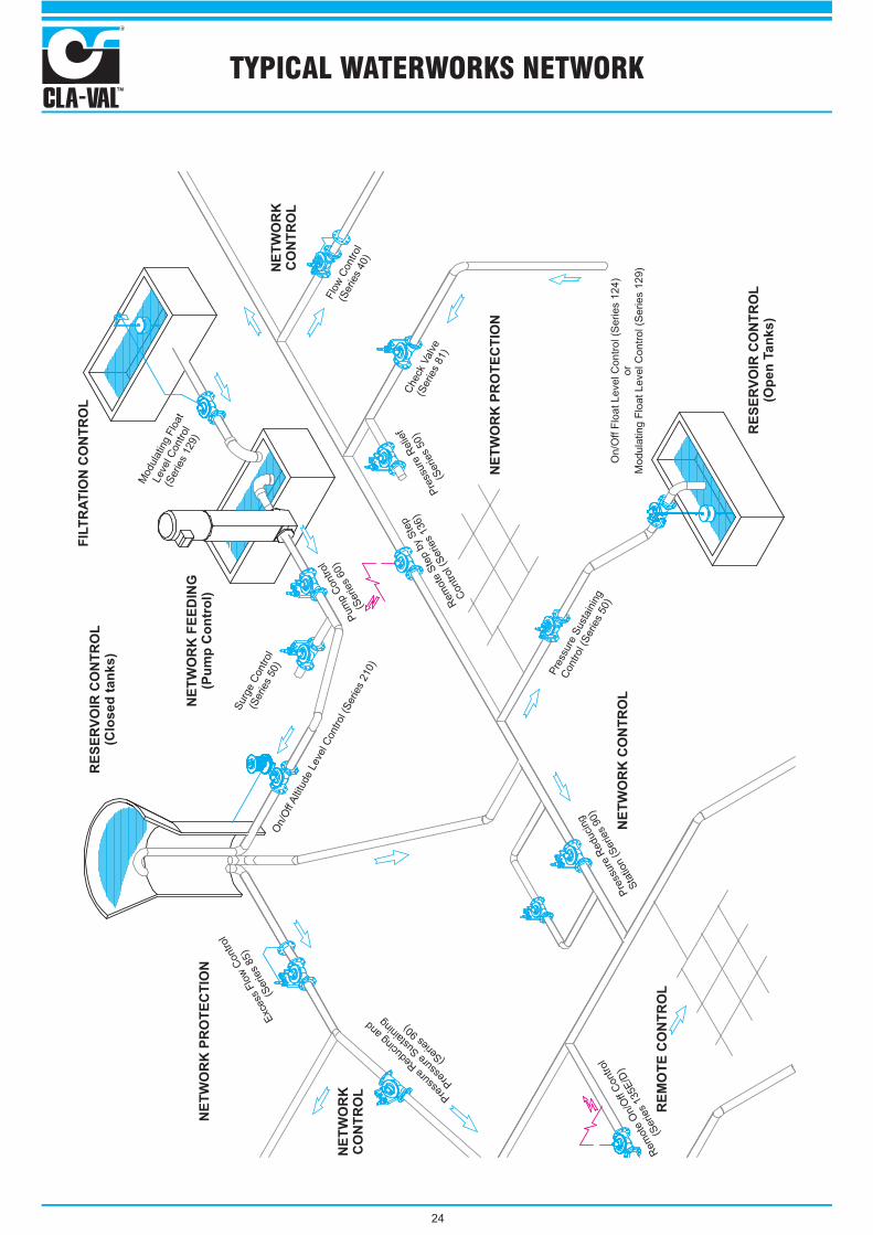
TYPICAL WATERWORKS NETWORK
24
INTRODUCTION
THE CLA-VAL DIFFERENCE
Control valves form an essential part of the effective and efficient operation of any pipeline system. Selection of these devices is highly dependant on the personal
experience of the engineer, the detail in manufacturer’s product literature and published imperical data. It is often assumed, due to the lack of published field data that
at least, all control valves are the same in performance. Control valves for this reason, are often specified based on the desired function or, for a perceived advantage
which may in essence have no bearing on the valve’s effectiveness.
As an integral component to any pipeline system, control valves should be selected as with all other pipeline components on the cost of ownership which implies
weighing up the initial cost of the valve against; maintenance, requirements, ease of installation, effectiveness of operation, availability of spares and, technical
support and after sales backup.
Cla-Val, when assessed against these requirements and for the reasons outlined below, is the most obvious choice for all your control valves needs.
Low flow conditions cannot be accommodated for in conventional control valves without the addition of paraphernalia such as Vee Ports and the like that may present
additional operational problems. Alternatively, expensive changes to the pipeline are recommended such as installation of reducing pieces and smaller diameter
valves or, installation of low flow bypasses.
Model 600 Cla-Val Hytrols provide a cost effective and efficient reduced port design to cope with low flow conditions.
High pressure drops or excessive flow conditions will inevitably cause cavitation which result in high noise, excessive vibration and damage to the valve. Designs
utilizing Vee Ports do not prevent but aggravate this destructive phenomenon. The use of multiple orifice plates is often not practical in applications where there is
limited space; in addition, the solution is removed from the valve and can lead to error in application.
The specific design of the model 600 CLa-Val with its enlarged flow area around the seat allows for vapour bubbles to slow down before disposing against the walls of
the valve housing, reducing potential cavitation damage. A ratio of 4 to 1 reductions in pressure can be maintained without damage.
In addition, Cla-Val provides a proven, radial design cartridge that can be fitted to its standard hytrol design for severe applications.
The stem of a control valve is often subjected to high differential pressures. Stems of Wye (Y) Pattern (sometimes called semi-straight) designs are centrally guided.
The inclined operation of the stem in addition to its central guidance often leads to excessive wear of the o-ring seals and bearings and subsequent leaks. Vee Ports,
which may cause a number of operational problems, are often specified to provide more controlled guidance to the stem.
The Cla-Val non-magnetic stem as standard is fully guided through its complete stroke by two replaceable bearings.
Pilot control systems form the heart of any control valve design. Most manufactures provide a limited selection of pilot controls or, make use of three way controls
which result in inaccuracy in control due to the shifting of the control point.
The two-way modulating control systems manufactured by Cla-Val are designed to minimize set point fluctuations. Stem movement of these controls are limited to
one-mm, hence the spring is compressed by one-mm maximum, and the modulus of the spring does not change over this distance of compression, resulting in the
set point remaining constant. Cla-Val in addition provides the widest selection of control systems.
It is prudent, regardless of design, to maintain control valves regularly. Large diameter, Wye (Y) pattern valves are difficult to maintain due to the bonnet installed at an
angle.
Cla-Val utilizes a globe pattern design and has only moving part which makes for ease of maintenance
Cla-Val has been available in South Africa since 1977 and has been locally manufactured, under licence to CLa-Val Co., by Dynamic Fluid Control (Pty) Ltd since
1981.
The Local market, because of this relationship has access to more than sixty five years of global experience in real world and demanding control valve operation in
applications such as waterworks distribution systems, fire protection systems, farm irrigation, navy ship systems, ground fueling and industrial fluid handling
systems. In addition, the market is updated and kept on the edge of technological advancement in electronic and hydraulic control systems through CLa-Val’s Co’s
aggressive and continued research and development program.
Cla-Val provides highly committed customer orientated sales, services, spares and technical back up - TRY US!
Low Flow Conditions
Resistance to Cavitation Damage
High Differential Pressure Applications
Sensitive and Critical Flow and Pressure set Points
Ease of Maintenance
Local Manufacture
Sales and Field Service
TM
R
WHY SPECIFY CLA-VAL AUTOMATIC CONTROL VALVES?
25