automatic control education using flightgear and matlab ......demonstrated in four experiments...
TRANSCRIPT

Proceedings of the 8th ICEENG Conference, 29-31 May, 2012 EE113 - 1
Military Technical CollegeKobry El-Kobbah,
Cairo, Egypt
8th International Conferenceon Electrical Engineering
ICEENG 2012
Automatic control education using FlightGear and MATLAB basedvirtual lab
By
M. Moness* A. M. Mostafa* M. A. Abdel-Fadeel* A. I. Aly* A. Al-Shamandy*
Abstract:
In this paper, a virtual lab based on MATLAB and FlightGear flight simulator isdiscussed and developed. The virtual lab consists of number of experiments thatenhances the understanding of fundamental concepts of classical control forundergraduate students. The objective of the virtual lab is to design a stabilityaugmentation system for C310 aircraft model according to known flying qualities thenimplement a hold autopilot for the aircraft. This objective is achieved through a series ofexperiments, animation and simulation to illustrate main concepts of classical controllike modeling, time domain analysis, frequency domain Analysis, non-minimum phasesystems, root locus, feedback design and PID compensation. These concepts aredemonstrated in four experiments through the analysis and design of a flight controlsystem for Cessna 310 aircraft on FlightGear flight simulator. The developed virtual labcan be used easily by students to study and visualize classical control principles usingFlightGear and MATLAB GUI with an attractive case study of a flight control system.
Keywords:
Virtual lab, automatic control education, flight simulator and FlightGear
ـــــــــــــــــــــــــــــــــــــــــــــــــــــــــــــــــــــــــــــــــــــــــــــــــــــــــــــــــــــــــــــــــــــــــــــــــــــــــــــــــــــــــــــــــ* Faculty of Engineering, Minia University, Minia, Egypt

Proceedings of the 8th ICEENG Conference, 29-31 May, 2012 EE113 - 2
1. Introduction:
A flight simulator represents a field of virtual engineering that tries to copy or tosimulate the experience of flying an aircraft as realistic as possible. Modeling andsimulation are important tools of virtual engineering. In this paper, we introduce a newtechnique for teaching control engineering with flight simulators. We build a virtual labusing MATLAB and the FlightGear flight simulator which is an open-source, multi-platform, cooperative flight simulator development project. The tasks of virtualengineering in flight systems – as stated by Zipfel [8]– are:
1. Developing performance requirements.2. Guiding and validating designs.3. Test support.4. Reducing test cost.5. Investigating inaccessible environments.6. Pilot and operator training.7. Practicing dangerous procedures.8. Gaining insight into flight dynamics.9. Integrating components.10. Entertainment.
We introduce a new task to the previous tasks:11. Control engineering education.
The FlightGear flight simulator implements number of flight dynamics models (FDM)libraries like: LaRCsim, YASim, UUIC, and JSBSim [6]. This paper aims to develop avirtual lab based on a flight control system for a JSBSim aircraft model that iscompatible with FlightGear. JSBSim is an open source flight dynamics model softwarelibrary that models the flight dynamics of a 6-DoF aerospace vehicle. The designedvirtual lab will use the flight control system to serve as a fun, rich and interesting casestudy for teaching control engineering. This case study will be organized in a lab coursewhich includes fundamental concepts for introductory automatic control courses andadvanced concepts for higher students. These concepts will be visualized in a virtualreality environment based on a flight simulator.
There are previous implementations of flight simulators for education. Bossert andYechout [2] used MATLAB with Genesis 3000 flight simulator for flight mechanicseducation. Munz et al. [10] developed a spacecraft simulator for advanced automaticcontrol education. Pavel and Martin [9] proposed a course implemented over anembedded graphics system simulator for teaching Board Information Systems (BIS)course.

Proceedings of the 8th ICEENG Conference, 29-31 May, 2012 EE113 - 3
2. Virtual Lab Architecture:
The virtual lab will be based on three components: a flight simulator virtual cockpit forvisual flight experiments, a powerful control system analysis and design software and alab manual that contains control experiments. This virtual lab is aimed to serve for awide range of students studying automatic control course in Computer, Electrical andMechanical Engineering.
We will use the FlightGear flight simulator based on the JSBSim FDM library and acontrol systems analysis tool like MATLAB and Simulink. In the following points, wewill introduce the role of each component to the education process (Figure 1):1. FlightGear Flight Simulator: Represents the virtual reality environment where the
three dimensions enhance the student understanding by visualizing flight designedexperiments.
2. JSBSim FDM: This flight dynamics library is developed by a number of aerospaceengineers, software engineers and mathematicians [5]. It plays the role of the plantthat needs to be analyzed, modeled and controlled.
3. MATLAB and Simulink: Engineering software where analysis and control design isperformed.
Figure (1): Control Education Process and Components
This virtual lab links between a ready-made control tool and a fancy graphicalrepresentation as suggested by Munz et al. [10] for choosing a platform for educationcontrol games.
3. The Cessna 310 Aircraf Model:
The aircraft model consists of number of subsystems. Each subsystem is responsible forgenerating the forces, moments and other physical variables that affects the aircraft

Proceedings of the 8th ICEENG Conference, 29-31 May, 2012 EE113 - 4
dynamics. Our aircraft model has five main subsystems as illustrated in Figure 2.
Figure (2): Aircraft Model Subsystems
The aircraft model is implemented in Simulink with the help of Simulink AerospaceBlockset and Aerosim Blockset by Unmanned Dynamics [11]. (Figure 3)
RAD DEG
rad 2 deg1
RAD DEG
rad 2 deg
M/S KTS
m/s 2 kts
M FT
m 2 ft
0
heading
2000
alt
130
airspeed
-C-
Wind
0.95
Throttle
Sideslip
Rates
du/dt
Rate
R2D
R2D
24
Prop pitch R
24
Prop pitch L
Airpseed
Throttle
Heading
Altitude
Climb Rate
Panel
1
On
0
Off
0.8
Mixture R
0.8
Mixture L
LON deg
LAT deg
1
Ignition R
1
Ignition L
HeadingHold
[Throttle]
Goto
GENFG
RUN
GenerateRun Script
0
Gear
60
-K-
[Throttle]
From
l,µ,h,φ,θ,ψ
FlightGearPreconfigured
6DoF AnimationVersion Selected: v1.0
Ve
Position
Euler
DCM
Wind Velocity
Wind Angular Rates
Gravity
Speed of Sound
Pressure
Temperature
Air Density
Environment Models
Demux
Demux
Demux
Demux
Altitude Hold
Heading Hold
Airspeed_Setpoint
Altitude_Setpoint
Heading_Setpoint
Euler Angles
Angular Rates
Position
Velocity|W
ThrottleCMD
FlapsCMD
ElevatorCMD (rad)
AileronsCMD (rad)
RudderCMD (rad)
Controller
Climb Rate (ft/min)
Attitude
Altitude (ft)
AltitudeHold
Wind Velocity
Wind Angular Rates
Gravity
Speed of Sound
Pressure
Temperature
Air Density
Engines Control
Control Surfaces
Gear
Ve (m)
Velocity|B (m/s)
Xe (m)
Position
Euler Angles (rad)
Angular Rates (rad/s)
DCM|be
Velocity|W
G
Aircraft Airframe
Activate Speed Hold
Acc
AOA deg
G
Throttle
Figure (3): C310 Aircraft Simulink Model

Proceedings of the 8th ICEENG Conference, 29-31 May, 2012 EE113 - 5
4. Wings Level Operating Point of the Aircraft Model:
We need to put the aircraft to equilibrium or a steady state. Then, we can analyze thedynamics of the aircraft by perturbing certain parameters. The aircraft model isinitialized with the conditions values and constraints of the steady state wings level. Weuse the gradient descent with elimination algorithm to perform an optimization to get anoperating point by using Simulink Control Design and MATLAB Control SystemToolbox. The operating point is computed using Tables 1 and 2.
Table (1): Internal state values at wings level operating point
State Value dxFuel Tank 1 Mass 106.8395 -0.00363Fuel Tank 2 Mass 112.962 -0.00363Fuel Tank 3 Mass 50.8198 -0.00363Fuel Tank 4 Mass 52.0338 -0.00363Engine 1 Speed 197.166 -1.6975e-10Engine 2 Speed 197.166 -1.7483e-10
0 00.047634 0
1.1593e-13 0P 0 8.3897e-15Q 0 -3.948e-13R 0 3.7523e-13U 63.7578 5.5257e-12V 0 2.6964e-22W 3.0394 4.5946e-14xe -3.2298e-12 63.8302ye 5.1201e-14 7.3996e-12ze -2251.3711 8.8818e-15
Table (2): Inputs values at wings level operating point
Inputs Initial Value0.82315
-2.2408e-200.2913
3.4323e-21

Proceedings of the 8th ICEENG Conference, 29-31 May, 2012 EE113 - 6
At this operating point, the model can be linearized to get both the aircraft longitudinaland lateral dynamics model.
5. Stability Augmentation System (SAS):
The feedback loops that force aircraft oscillation modes to the flying qualities are calledstability augmentation system (SAS). SAS is essential to achieve the aircraft dynamicstability. SAS is separately designed for the longitudinal and the lateral dynamicsdepending on the decoupling of the aircraft dynamics as illustrated by Stevens andLewis [1], Blakelock [3], and Roskam [4].
5.1. Longitudinal Stability Augmentation System:
The main purpose of the longitudinal SAS is to give satisfactory natural frequency anddamping ratio for short period mode and to pull the short period poles from the overdamped region to the under damped region with frequency of 0.4 to 0.6 rad/secsuggested by the flying qualities described in [1] and [7]. Possible feedbacks forlongitudinal SAS are illustrated in Figure 4.
Figure (4): Longitudinal SAS Possible Feedbacks
5.2. Lateral Stability Augmentation System:
The lateral SAS is intended to perform the following:1. The roll subsidence mode and spiral mode time constants meet the flying qualities.2. A roll damper is needed to eliminate the Dutch roll mode from the ailerons to roll rate
transfer function and speed up roll rate.3. A yaw damper is needed to generate an opposite yawing moment to eliminate any
yaw that builds up from the Dutch roll mode.

Proceedings of the 8th ICEENG Conference, 29-31 May, 2012 EE113 - 7
Figure 5 shows the block diagram of lateral directional stability feedback system:
Figure (5): Lateral SAS Block Diagram
6. Hold Autopilot Design:
The autopilot is usually designed to meet specifications of steady state error anddisturbance rejection with less concentration on dynamic response. The hold autopilotfunctions can be divided for the aircraft with respect to its dynamics into longitudinalhold autopilots and lateral hold autopilots. (Error! Reference source not found.)
Table (3): Hold Autopilots for C310
Longitudinal Hold Lateral Hold1. Pitch Attitude Hold2. Altitude Hold3. Airspeed Hold
1. Bank Angle Hold2. Heading Angle Hold
6.1. Pitch Attitude Hold:
The purpose of pitch attitude hold autopilot is to make the pitch attitude angle constantat certain value determined by the pilot. It is rarely used alone. The pitch attitude holdautopilot is an internal autopilot mode where other autopilots can be closed around likethe airspeed hold autopilot and the altitude hold autopilot. The pitch attitude holdautopilot compensator is closed around the pitch axis stability augmentation systems.The final block diagram of the pitch attitude hold autopilot is shown in Figure 6:

Proceedings of the 8th ICEENG Conference, 29-31 May, 2012 EE113 - 8
Figure (6):Pitch Attitude Hold Autopilot Block Diagram
6.2. Altitude Hold:
The main objective of the altitude hold autopilot is to keep the aircraft flying at analtitude set point defined by the pilot. It also needs to consider the aircraft maximumclimb rate and maximum descend rate of the aircraft when reaching a set point. Thealtitude hold can be built around either the pitch attitude hold or the airspeed hold. Inour design, we will build the altitude hold autopilot around the pitch hold. The finalblock diagram of the altitude hold autopilot is shown in Figure 7.
Figure (7):Altitude Hold Autopilot Block Diagram
6.3. Airspeed Hold:
The main objective of the airspeed hold autopilot is to keep the aircraft flying at aconstant airspeed defined by the pilot. The airspeed hold can be built in two ways. It can

Proceedings of the 8th ICEENG Conference, 29-31 May, 2012 EE113 - 9
be either around the pitch attitude hold autopilot or by closing the loop from theairspeed to throttle. In our design, we chose the second scheme. The final airspeedautopilot block diagram is shown in Figure 8.
Figure (8):Airspeed Hold Autopilot Block Diagram
6.4. Bank Angle:
The purpose of bank angle hold autopilot is to make the bank angle constant at certainvalue determined by the pilot. It is rarely used alone except for wings level hold. Thebank angle hold autopilot is an internal autopilot mode where we will close the headinghold autopilot around. The bank angle will be closed around the lateral directionalstability augmentation system. We will use the ailerons input and set the rudder input tozero. These concepts are illustrated by Figure 9.
Figure (9):Bank Angle Hold Autopilot Block Diagram
6.5. Heading Hold:
The main objective of the heading hold autopilot is to keep the aircraft at a heading setpoint defined by the pilot. The heading hold autopilot will be closed around the bankangle hold autopilot with input of reference heading angle (ψC) and output yaw angle.

Proceedings of the 8th ICEENG Conference, 29-31 May, 2012 EE113 - 10
Figure 10 shows the block diagram of the heading hold autopilot.
Figure (10):Heading Hold Autopilot Block Diagram
7. Design of Flight Control System Virtual Lab:
The proposed design of the virtual lab consists of 4 experiments: Linearization of thenonlinear aircraft model, analysis of the dynamic modes of the aircraft and the flyingqualities, feedback design of the stability augmentation system and PID controllerdesign for the hold autopilots.
7.1. Linearization Experiment:
The first experiment to be illustrated is linearization. A nonlinear system such anaircraft has multiple inputs and outputs. A nonlinear system needs to be linearizedbefore it can be handled using classical control analysis and design. The GUI window ofthis experiment is shown in Figure 11.
As shown in Error! Reference source not found. the nonlinear and linearized modelsare close with small error at the same operating point using wings level operating point,but after changing the operating point into steady turning the output of the linearizedmodel has a higher error.
7.2. Analysis of the Aircraft Dynamics Experiment:
Proceedings of the 8th ICEENG Conference, 29-31 May, 2012 EE113 - 11
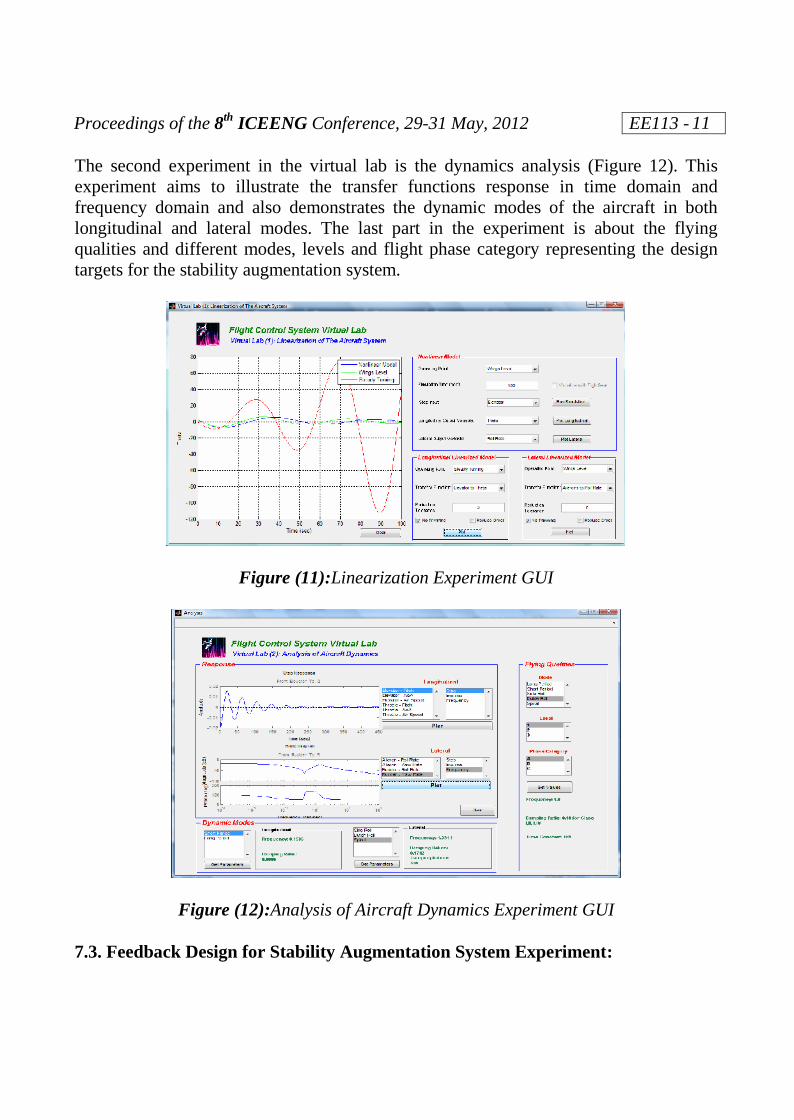
The second experiment in the virtual lab is the dynamics analysis (Figure 12). Thisexperiment aims to illustrate the transfer functions response in time domain andfrequency domain and also demonstrates the dynamic modes of the aircraft in bothlongitudinal and lateral modes. The last part in the experiment is about the flyingqualities and different modes, levels and flight phase category representing the designtargets for the stability augmentation system.
Figure (11):Linearization Experiment GUI
Figure (12):Analysis of Aircraft Dynamics Experiment GUI
7.3. Feedback Design for Stability Augmentation System Experiment:

Proceedings of the 8th ICEENG Conference, 29-31 May, 2012 EE113 - 12
The feedback design for stability augmentation experiment is designed to apply thefeedback required and monitor the effect on the step response and root locus design. Thefeedback is applied to shape the dynamics of both the longitudinal and lateral modes toget the targeted flying qualities of the aircraft. Figure 13 shows the all GUI componentsof this experiment.
7.4. PID Design for Hold Autopilots Experiment:
After the linearization, analysis and stability augmentation processes, the last phase in isto design the autopilot controller. This experiment (Figure 14) illustrates the PIDcontroller and to maintain hold functions for some aircraft parameters like pitch attitude,altitude, bank angle, heading and airspeed.
Figure (13):Feedback Design for SAS Experiment GUI

Proceedings of the 8th ICEENG Conference, 29-31 May, 2012 EE113 - 13
Figure (14):PID Design for Hold Autopilot Experiment GUI7.5. Visualization of the Experiments:
The SAS and hold autopilot experiments can be visualized by linking the C310aircraft Simulink model to the FlightGear flight simulator to give an experience ofreality as shown in Figure 15 and Figure 16. The FlightGear flight simulator provides arich and good graphical representation and animation. The graphical representation andexperience of reality were problems in SpacecraftRT developed by Munz et al. [10].
Figure (15):FlightGear Visualization of the C310 Aircraft and Panel

Proceedings of the 8th ICEENG Conference, 29-31 May, 2012 EE113 - 14
Figure (16):Simplified Flight Panel in Simulink8. Conclusion:
This paper has implemented four experiments for control engineering education. Thefour control experiments were built as MATLAB GUIs with link to FlightGear FlightSimulator for visualization. The four experiments discussed: Linearization andoperating points, analysis in time domain and frequency domain, feedback design byroot locus, and PID Control. Discussion, analysis and design of a flight control systemof a FlightGear aircraft show that it can be a great tool with fun and wealthy examplesfor control problems.
References:
[1] B. L. Stevens, and F. L. Lewis, Aircraft Control and Simulation, John Wiley andSons, 1992.
[2] D. E. Bossert and T. R. Yechout, A MATLAB-Based Flight Simulator for FlightMechanics Education, AIAA Atmospheric Flight Mechanics Conference andExhibit, AIAA 2002-4876, August 2002.
[3] J. H. Blakelock, Automatic Control of Aircraft and Missiles, 2nd Edition, JohnWiley and Sons, 1991.
[4] J. Roskam, Airplane Flight Dynamics and Automatic Flight Control,DARcorportation, 2001.
[5] J. S. Berndt and the JSBSim Development Team, JSBSim: An open-source,Platform-independent, Flight Dynamics Model in C++, http://www.JSBSim.org,2008.

Proceedings of the 8th ICEENG Conference, 29-31 May, 2012 EE113 - 15
[6] M. Basler, M. Spott, S. Buchanan, J. Berndt, B. Buckel, C. Moore, C. Olson, D.Perry, M. Selig, D. Walisser et al, The FlightGear Manual,http://www.flightgear.org/, 2008.
[7] M. V. Cook, Flight Dynamics Principles, A Linear Approach to Aircraft Stabilityand Control, 2nd Edition, Elsevier, 2007.
[8] P. H. Zipfel, Modeling and Simulation of Aerospace Vehicle Dynamics, AIAA,2007.
[9] P. Pavel and S. Martin, Introducing Students to Aerospace Board InformationSystems, Using an Embedded Graphics Systems Simulator, 10th IEEEInternational Conference on Advanced Learning Technologies (ICALT), pp. 397–399, July 2010.
[10] U. Munz, C. Bohm, J. Ech, M. Reble, P. Schumm and F. Allgower, A Matlab-Based Game for Advanced Automatic Control Education. Stuttgart ResearchCentre for Simulation Technology (SRC SimTech) Issue No. 2009-40, October2009.
[11] Unmanned Dynamics, Aerosim: Aeronautical Simulation Blockset v1.2 User’sGuide, http://www.u-dynamics.com/aerosim/, 2005.
Nomenclatures:
… Angle of attack (rad)… Ailerons Deflection… Elevator Deflection… Rudder Deflection… Throttles Input… Roll Angle (rad)… Pitch Angle (rad)… Yaw Angle(rad)
P … Roll Rate (rad/s)Q … Pitch Rate (rad/s)R … Yaw Rate (rad/s)U … Axial Velocity (m/s)V … Lateral Velocity (m/s)
VT … Airspeed (knots)W … Normal Velocity (m/s)xe … X coordinate in Flat Earth Frame (m)ye … Y coordinate in Flat Earth Frame (m)ze … Z coordinate in Flat Earth Frame (m)