automatic control: future challenges, solutions, and...
TRANSCRIPT

Automatic Control: Future Challenges, Solutions, and Systems
Terry Blevins, Principal Technologist

Agenda
• Introduction
• State of Process Control Systems
• Evolving ISA106 Standard which addresses Procedure Automation for Continuous Process Operations
• Impact of State Driven Procedure Automation
• Factors limiting full automation of Startup/Shutdown/Transitions and technical solutions.
• Wireless Field Devices role in Procedure Automation
• Structuring Distributed Control Systems (DCS) to support early detection and correction of abnormal operation
• Technology role in the design of future DCS
• Conclusions
Process Control Industry
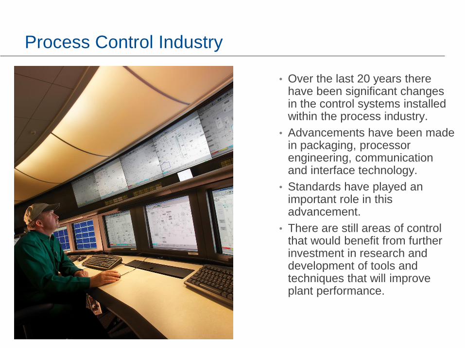
• Over the last 20 years there have been significant changes in the control systems installed within the process industry.
• Advancements have been made in packaging, processor engineering, communication and interface technology.
• Standards have played an important role in this advancement.
• There are still areas of control that would benefit from further investment in research and development of tools and techniques that will improve plant performance.
Process Industry – Control System Market
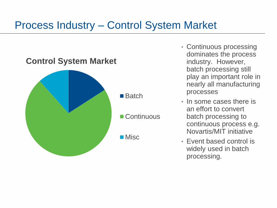
• Continuous processing dominates the process industry. However, batch processing still play an important role in nearly all manufacturing processes
• In some cases there is an effort to convert batch processing to continuous process e.g. Novartis/MIT initiative
• Event based control is widely used in batch processing.
Control System Market
Batch
Continuous
Misc
Batch control – Advancements
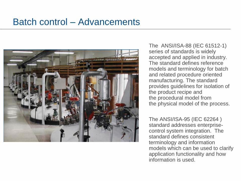
The ANSI/ISA-88 (IEC 61512-1) series of standards is widely accepted and applied in industry. The standard defines reference models and terminology for batch and related procedure oriented manufacturing. The standard provides guidelines for isolation of the product recipe and the procedural model from the physical model of the process.
The ANSI/ISA-95 (IEC 62264 ) standard addresses enterprise-control system integration. The standard defines consistent terminology and information models which can be used to clarify application functionality and how information is used.
Standards for Batch Automation
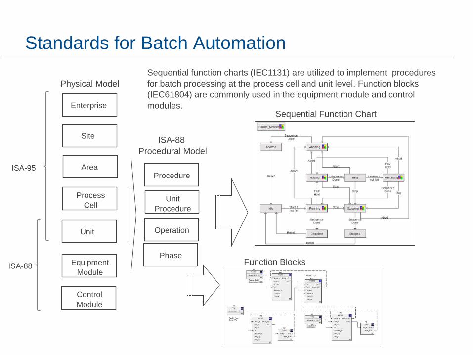
Enterprise
Site
Area
Process
Cell
Unit
Equipment
Module
Control
Module
Physical Model
ISA-95
ISA-88
Procedure
Unit
Procedure
Operation
Phase
ISA-88
Procedural Model
Sequential function charts (IEC1131) are utilized to implement procedures
for batch processing at the process cell and unit level. Function blocks
(IEC61804) are commonly used in the equipment module and control
modules. Sequential Function Chart
Function Blocks
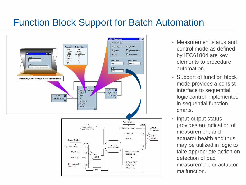
Function Block Support for Batch Automation
• Measurement status and
control mode as defined
by IEC61804 are key
elements to procedure
automation.
• Support of function block
mode provides a consist
interface to sequential
logic control implemented
in sequential function
charts.
• Input-output status
provides an indication of
measurement and
actuator health and thus
may be utilized in logic to
take appropriate action on
detection of bad
measurement or actuator
malfunction.
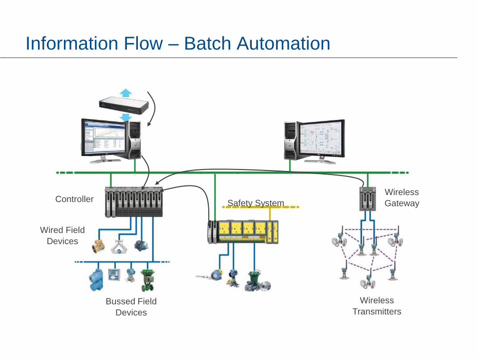
Information Flow – Batch Automation
Wireless
Transmitters
Safety System
Bussed Field
Devices
Wired Field
Devices
Controller Wireless
Gateway

Instrumentation for Batch Automation
• Batch applications such as those typically found in specialty chemical industry are often fully automated i.e. process startup, run, shutdown .
• It is possible to justify instrumenting the process with remotely activated on-off valves for flow line isolation because the time to produce a batch is relative short e.g. few hours or a few days.
• Electrically actuated on-off valves can provide the control systems with positive confirmation /verification of device status and state of the valve i.e. open, closed or in transition.

Challenges in Batch Automation
• One of the greatest challenges in producing a consistent product is variations in feedstock and use of multiple units in manufacturing.
• Changes in the process that impact the final product may go undetected until they are found at the end of the batch
• Often lab analysis of a grab sample at the end of a batch is the only available measure of product quality parameters. Laboratory Information Management Systems (LIMS) may not be integrated into the control system.

Batch Analytics – Fault Detection and Quality Parameter Prediction
Multi-way Models
Evaluating
processes in
real time
Historical Data
Raw Material Composition
Process measurements
Monitoring Interface
Impact evaluation/Quality Prediction
Process capability /Fault Detection
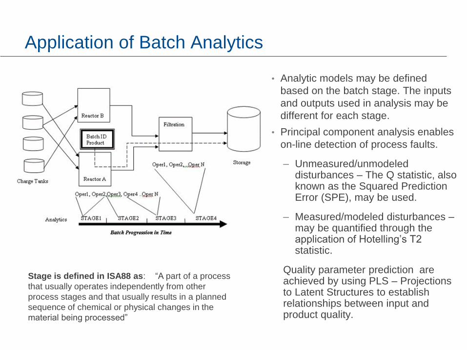
Application of Batch Analytics
• Analytic models may be defined
based on the batch stage. The inputs
and outputs used in analysis may be
different for each stage.
• Principal component analysis enables
on-line detection of process faults.
– Unmeasured/unmodeled disturbances – The Q statistic, also known as the Squared Prediction Error (SPE), may be used.
– Measured/modeled disturbances – may be quantified through the application of Hotelling’s T2 statistic.
Quality parameter prediction are achieved by using PLS – Projections to Latent Structures to establish relationships between input and product quality.
Stage is defined in ISA88 as: “A part of a process
that usually operates independently from other
process stages and that usually results in a planned
sequence of chemical or physical changes in the
material being processed”
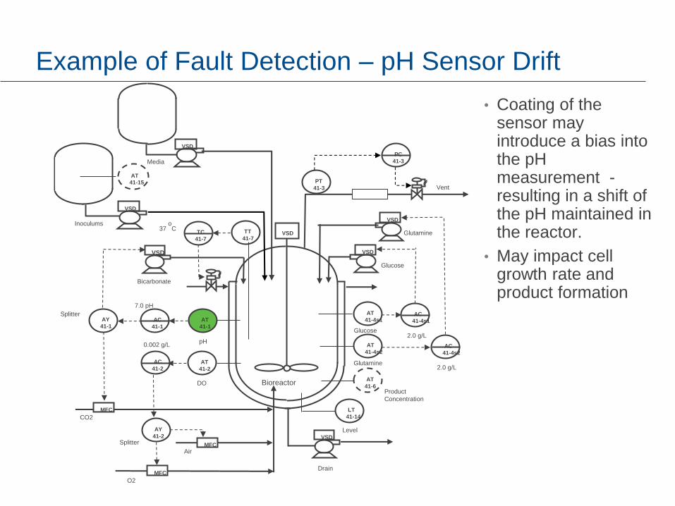
Example of Fault Detection – pH Sensor Drift
O2
Bioreactor
VSD
VSD
TC
41-7
AT
41-4s2
AT
41-4s1
AT
41-2
AT
41-1
TT
41-7
AT
41-6
LT
41-14
Glucose
Glutamine
pH
DO
Product
Concentration
VSD
VSD
AC
41-4s1
AC
41-4s2
Media
Glucose
Glutamine
VSD
Bicarbonate
AY
41-1 AC
41-1
Splitter
AC
41-2
AY
41-2 Splitter
CO2
Air
Level
Drain
0.002 g/L
7.0 pH
2.0 g/L
2.0 g/L
37 oC
VSD
Inoculums
VSD
PT
41-3 Vent
MFC
MFC
MFC
PC
41-3
AT
41-15
• Coating of the sensor may introduce a bias into the pH measurement - resulting in a shift of the pH maintained in the reactor.
• May impact cell growth rate and product formation

Example of Fault Detection – pH Sensor Drift
• Fault shows up as an explained and unexplained change – deviation above 1.
• To find the cause of the fault, select the point of maximum deviation and then choose the Contribution Tab.
Emerson Confidential, March, 2009
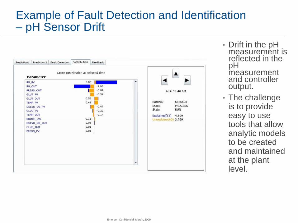
Example of Fault Detection and Identification – pH Sensor Drift
• Drift in the pH measurement is reflected in the pH measurement and controller output.
• The challenge is to provide easy to use tools that allow analytic models to be created and maintained at the plant level.
Emerson Confidential, March, 2009

Continuous Process Control
• Primary focus within the process industry has been on optimization of on-line operation through control design, commissioning and application of advanced control techniques such as Model Predictive Control (MPC) and extensive application of wireless devices in control.
• The operator is still required to address infrequent procedures such as startup, process transitions such as product grade change or process shutdown.
• Automatic control often must be placed on manual during startup/shutdown or production transitions. Results are highly dependent of the skill of the operator on a shift.
• Retiring workforce and retention of knowledge base is a continuouos challenge.
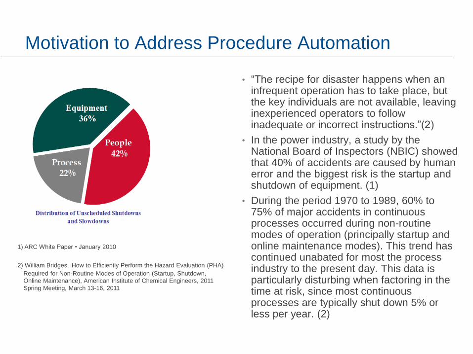
Motivation to Address Procedure Automation
• “The recipe for disaster happens when an infrequent operation has to take place, but the key individuals are not available, leaving inexperienced operators to follow inadequate or incorrect instructions.”(2)
• In the power industry, a study by the National Board of Inspectors (NBIC) showed that 40% of accidents are caused by human error and the biggest risk is the startup and shutdown of equipment. (1)
• During the period 1970 to 1989, 60% to 75% of major accidents in continuous processes occurred during non-routine modes of operation (principally startup and online maintenance modes). This trend has continued unabated for most the process industry to the present day. This data is particularly disturbing when factoring in the time at risk, since most continuous processes are typically shut down 5% or less per year. (2)
1) ARC White Paper • January 2010
2) William Bridges, How to Efficiently Perform the Hazard Evaluation (PHA)
Required for Non-Routine Modes of Operation (Startup, Shutdown,
Online Maintenance), American Institute of Chemical Engineers, 2011
Spring Meeting, March 13-16, 2011
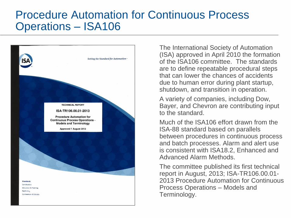
Procedure Automation for Continuous Process Operations – ISA106
The International Society of Automation (ISA) approved in April 2010 the formation of the ISA106 committee. The standards are to define repeatable procedural steps that can lower the chances of accidents due to human error during plant startup, shutdown, and transition in operation.
A variety of companies, including Dow, Bayer, and Chevron are contributing input to the standard.
Much of the ISA106 effort drawn from the ISA-88 standard based on parallels between procedures in continuous process and batch processes. Alarm and alert use is consistent with ISA18.2, Enhanced and Advanced Alarm Methods.
The committee published its first technical report in August, 2013; ISA-TR106.00.01-2013 Procedure Automation for Continuous Process Operations – Models and Terminology.

ISA 106 - Membership

ISA-106 – Models for Procedure Automation
Three models* are defined for procedural automation of continuous processes:
1. Physical model
2. Procedure requirements model
3. Procedure implementation model
The ISA106 physical model contains both process equipment and instrumentation (e.g. transmitters) which is the basic process control system’s (BPCS’s) connection to the process
Device
Physical Model
Procedure
Requirements Model
Enterprise
Procedure
Requirements
Site Procedure
Requirements
Plant Procedure
Requirements
Plant Area
Procedure
Requirements
Unit Procedure
Requirements
Control
Requirements
Equipment
Procedure
Requirements
Equipment
Unit
Plant Area
Plant
Site
Enterprise
Site
Implementation
Modules
Plant
Implementation
Modules
Plant Area
Implementation
Modules
Unit
Implementation
Modules
Equipment
Implementation
Modules
Control
Implementation
Modules
Procedure
Implementation Model
ISA-95
ISA-88
*ISA-TR106.00.01-2013 Procedure Automation for Continuous Process Operations

Example of Mapping to Physical Model
TT
306
LT
307
TT
305
Continuous
Reactor
Coolant
Discharge
PT
304
Vent
System
Feed A
FT
301
Feed B
FT
302
AT
303
FC
TV
306
FC
LV
307
FC
FV
302
FC
FV
301
FC
PV
304
Device
Equipment
Unit
The physical model illustrates how each area of a plant is made up of different levels of
equipment and components down to individual devices.

Implementation - Module Content
• Implementation modules consist of a set of ordered tasks*. Each task provides operations with step-by-step instructions for accomplishing the actions that are to be performed and their verification.
• Each Procedure implementation module and task has three execution work items;
1. Command – Trigger (Event)
2. Perform – Actions
3. Verify – Success/failure.
• Implementation methods are any type of tools used to create a task e.g. programming, continuous control, human actions.
• Some types of programming that may be used include: configurable function blocks, sequential function charts (SFC), continuous control functions, computer program, executable flowcharts.
• Operator displays show alerts, prompts and status notifications on separate displays for compliance with ANSI/ISA 18.2.
Task
Task
Task
Task
Human
Interface
Notifications
Commands
Peer to
Peer
Commands
and
Notifications
Commands Notifications
*ISA-TR106.00.01-2013 Procedure Automation for Continuous Process Operations
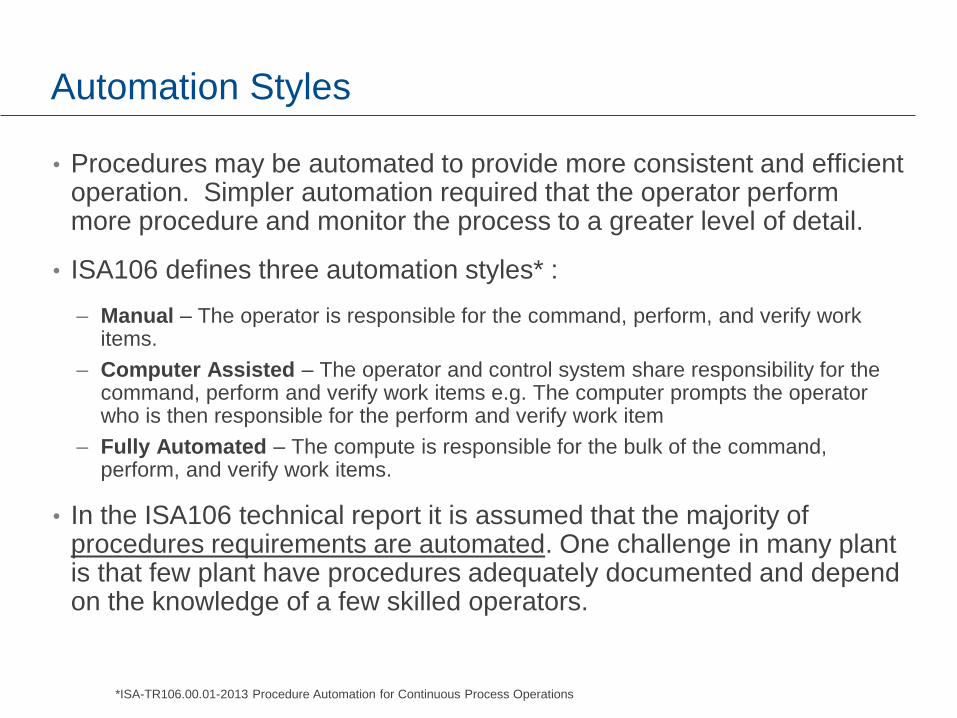
Automation Styles
• Procedures may be automated to provide more consistent and efficient operation. Simpler automation required that the operator perform more procedure and monitor the process to a greater level of detail.
• ISA106 defines three automation styles* :
– Manual – The operator is responsible for the command, perform, and verify work items.
– Computer Assisted – The operator and control system share responsibility for the command, perform and verify work items e.g. The computer prompts the operator who is then responsible for the perform and verify work item
– Fully Automated – The compute is responsible for the bulk of the command, perform, and verify work items.
• In the ISA106 technical report it is assumed that the majority of procedures requirements are automated. One challenge in many plant is that few plant have procedures adequately documented and depend on the knowledge of a few skilled operators.
*ISA-TR106.00.01-2013 Procedure Automation for Continuous Process Operations
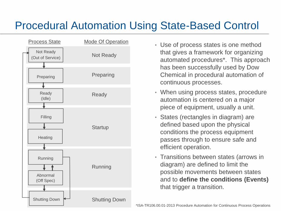
Procedural Automation Using State-Based Control
• Use of process states is one method
that gives a framework for organizing
automated procedures*. This approach
has been successfully used by Dow
Chemical in procedural automation of
continuous processes.
• When using process states, procedure
automation is centered on a major
piece of equipment, usually a unit.
• States (rectangles in diagram) are
defined based upon the physical
conditions the process equipment
passes through to ensure safe and
efficient operation.
• Transitions between states (arrows in
diagram) are defined to limit the
possible movements between states
and to define the conditions (Events)
that trigger a transition.
Not Ready
(Out of Service)
Preparing
Ready
(Idle)
Filling
Heating
Running
Abnormal
(Off Spec)
Shutting Down
Process State Mode Of Operation
Not Ready
Preparing
Ready
Startup
Running
Shutting Down
*ISA-TR106.00.01-2013 Procedure Automation for Continuous Process Operations

Mapping Implementation Modules to the Basic Process Control System(BPCS)
• Implementation modules are run in a basic process control system (BPCS) controller or a BPCS application server*.
• When a task’s implementation method results in a task that cannot be run by a computer, it is considered a manual procedure. Some of the implementation modules may be performed by a field operator using a printed or handheld electronic checklist.
• Automated procedures may interact with other BPCS functions such as regulatory control and interlocking.
Manual Procedures
Operator
Application Server
Procedure
Implementation
Modules
Human Machine
Interface
Controller
Procedure
Implementation
Modules
Outputs Inputs
Safety Instrumented
System
Auxiliary control system
(PLC, compressor control, skid,
robot, vision,…)
Basic Process
Control System
*ISA-TR106.00.01-2013 Procedure Automation for Continuous Process Operations

Dow Chemical Experience Using Procedural Automation
• Dow is a major contributor to development of the ISA106 standard. State Based Control has been applied in around 200 Dow plants globally. 75% of Dow Assets are run using state based control*
• The Mod5™ series of control systems develop by Dow was initially used for procedural automation, but more recently the ABB platform has been used for procedural automation.
• In one recent example, Dow reported the reduction in shutdown time achieved by automating cleaning procedures resulted in a 16% increase in plant profit.
Shorter Maintenance
Faster Shutdown
Faster Startup
*Procedural Automation State Based Control, Yahya Nazer,
Janette Brightwell, ARC Forum, 2015

CHS - State based procedural automation
The largest cooperative refiner in the United States, CHS, is using
procedural automation in the plant. One of CHS’s technical leaders,
Jay Colclazier, provided the following insight into their application of
state based procedural automation using the DeltaV control system:
Our refinery has used sequencing within our continuous control strategies for many years. We have found value in doing this in a number of areas.
1. Automated sequences associated with startups and shutdown eliminate many operator errors, particularly with processes that are operated for long periods of time between startups.
2. Automated sequences remove much of the operator-to-operator variability that is inherent in manual operations.
3. Automated sequences reduce the amount of time that the operator must spend and allows them the focus on exceptions rather than the routine tasks.

CHS Examples – Coke Drum:
The steam out and quenching
process needed to stop the reaction
and cool the drum before the coke
can be cut in our 2-drum delayed
coker unit was the perfect place for
procedural automation.
This process takes several hours to
perform and has been fully
automated using pre-programmed
sequences.
It has been so well received that
operators are asking if the spalling
sequence can be automated.
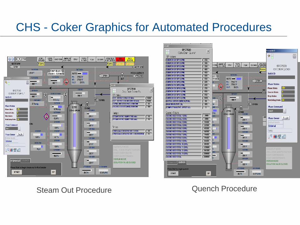
CHS - Coker Graphics for Automated Procedures
Steam Out Procedure Quench Procedure

CHS - Fired Heater Startups:
Many of the fired heater startup
sequences are automated. This
includes pre-startup firebox purges,
making sure permissives are satisfied,
opening fuel block valves, energizing
igniters and flame verification.

CHS - Compressor Controls:
CHS has automated the startup, shutdown and
transfer sequences on a large 6000 HP centrifugal
hydrogen compressor in the Hydrocracker Unit. The
4160V motor on the compressor can be operated
across-the-line at fixed speed or with a large variable
frequency drive. Automated sequences control the
startup, shutdown and transfer between VFD and
fixed speed modes. These sequences provide
coordination between the VFD, the high voltage
switchgear and the DeltaV-based anti-surge control.
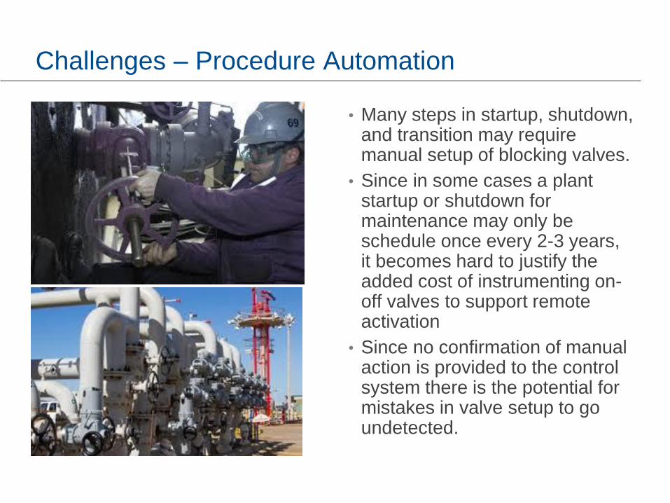
Challenges – Procedure Automation
• Many steps in startup, shutdown, and transition may require manual setup of blocking valves.
• Since in some cases a plant startup or shutdown for maintenance may only be schedule once every 2-3 years, it becomes hard to justify the added cost of instrumenting on-off valves to support remote activation
• Since no confirmation of manual action is provided to the control system there is the potential for mistakes in valve setup to go undetected.

Valve Position Monitoring – Remote Activation
• Wireless valve monitoring can be added to manual valve at minimal cost.
• Provides confirmation of valve on-close status for use in automation of startup and shutdown procedure.
• Reduced the need for visual inspections and improved safety, preventing workers from traveling into hazardous areas
• Wireless on-off actuators may be added to existing manual valves to allow remote activation and sensing of position.
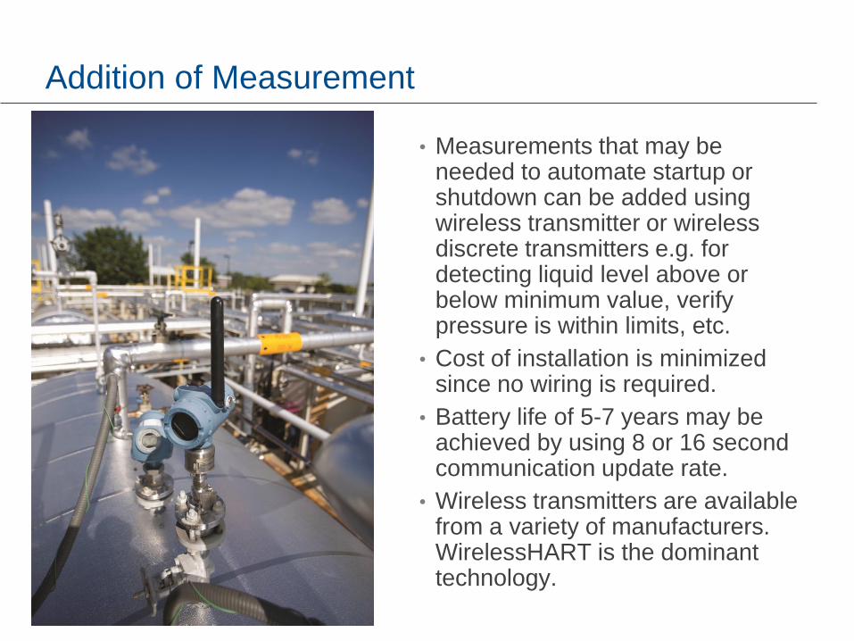
Addition of Measurement
• Measurements that may be needed to automate startup or shutdown can be added using wireless transmitter or wireless discrete transmitters e.g. for detecting liquid level above or below minimum value, verify pressure is within limits, etc.
• Cost of installation is minimized since no wiring is required.
• Battery life of 5-7 years may be achieved by using 8 or 16 second communication update rate.
• Wireless transmitters are available from a variety of manufacturers. WirelessHART is the dominant technology.
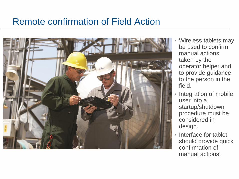
Remote confirmation of Field Action
• Wireless tablets may be used to confirm manual actions taken by the operator helper and to provide guidance to the person in the field.
• Integration of mobile user into a startup/shutdown procedure must be considered in design.
• Interface for tablet should provide quick confirmation of manual actions.
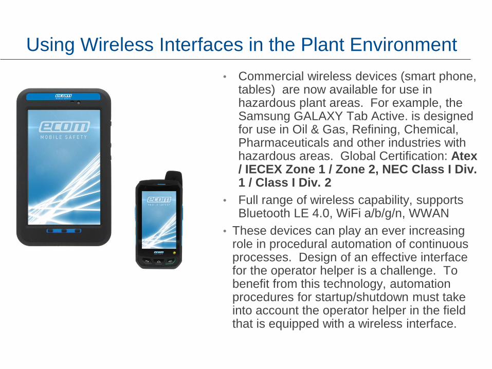
Using Wireless Interfaces in the Plant Environment
• Commercial wireless devices (smart phone, tables) are now available for use in hazardous plant areas. For example, the Samsung GALAXY Tab Active. is designed for use in Oil & Gas, Refining, Chemical, Pharmaceuticals and other industries with hazardous areas. Global Certification: Atex / IECEX Zone 1 / Zone 2, NEC Class I Div. 1 / Class I Div. 2
• Full range of wireless capability, supports Bluetooth LE 4.0, WiFi a/b/g/n, WWAN
• These devices can play an ever increasing role in procedural automation of continuous processes. Design of an effective interface for the operator helper is a challenge. To benefit from this technology, automation procedures for startup/shutdown must take into account the operator helper in the field that is equipped with a wireless interface.
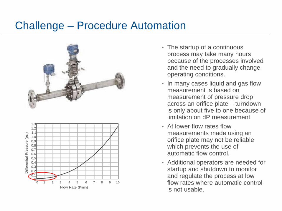
Challenge – Procedure Automation
• The startup of a continuous process may take many hours because of the processes involved and the need to gradually change operating conditions.
• In many cases liquid and gas flow measurement is based on measurement of pressure drop across an orifice plate – turndown is only about five to one because of limitation on dP measurement.
• At lower flow rates flow measurements made using an orifice plate may not be reliable which prevents the use of automatic flow control.
• Additional operators are needed for startup and shutdown to monitor and regulate the process at low flow rates where automatic control is not usable.
0 1 2 3 4 5 6 7 8 9 10
1.3
1,2
1,1
1.0
0.9
0.8
0.7
0.6
0.5
0.4
0.3
0.2
0.1
0
Flow Rate (l/min)
Diffe
rential P
ressure
(psi)
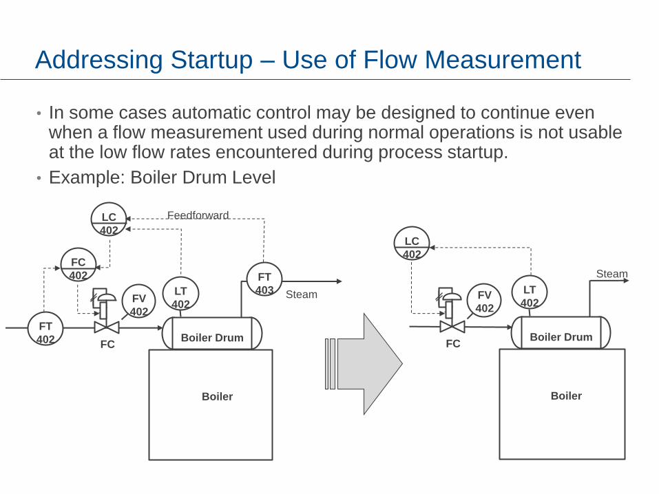
Addressing Startup – Use of Flow Measurement
• In some cases automatic control may be designed to continue even when a flow measurement used during normal operations is not usable at the low flow rates encountered during process startup.
• Example: Boiler Drum Level
Boiler Drum
LT
402
LC
402
Steam
Boiler
FC
FV
402
Boiler Drum
FC
402
FT
402
FT
403 LT
402
LC
402
Steam
Boiler
Feedforward
FC
FV
402
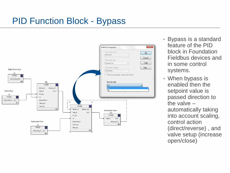
PID Function Block - Bypass
• Bypass is a standard feature of the PID block in Foundation Fieldbus devices and in some control systems.
• When bypass is enabled then the setpoint value is passed direction to the valve – automatically taking into account scaling, control action (direct/reverse) , and valve setup (increase open/close)
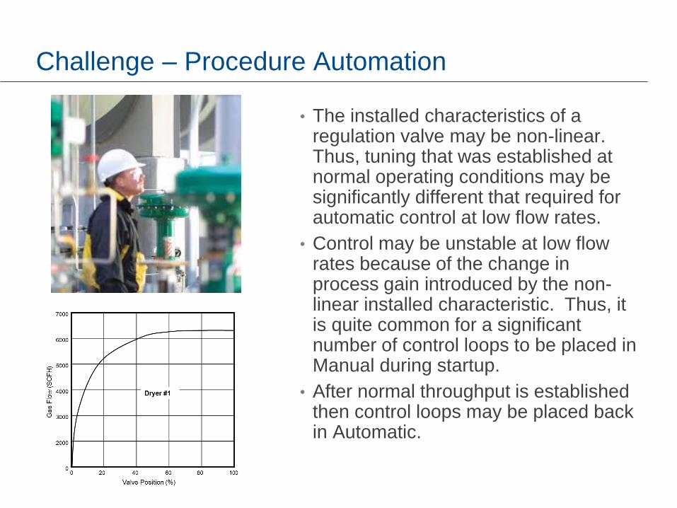
Challenge – Procedure Automation
• The installed characteristics of a regulation valve may be non-linear. Thus, tuning that was established at normal operating conditions may be significantly different that required for automatic control at low flow rates.
• Control may be unstable at low flow rates because of the change in process gain introduced by the non-linear installed characteristic. Thus, it is quite common for a significant number of control loops to be placed in Manual during startup.
• After normal throughput is established then control loops may be placed back in Automatic.
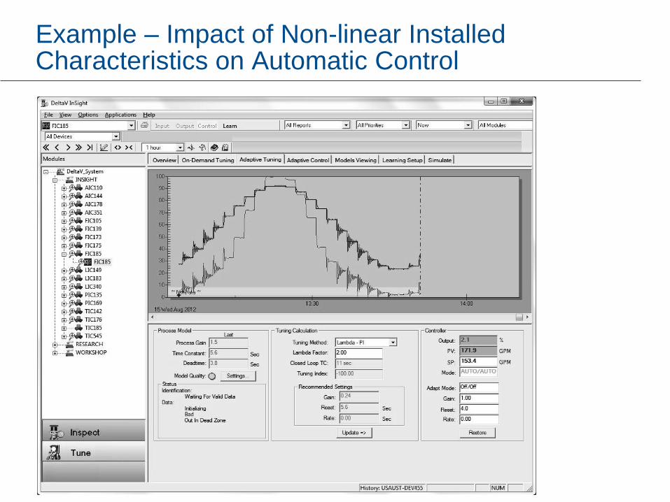
Example – Impact of Non-linear Installed Characteristics on Automatic Control

Accounting for Process Non-linearity
• The PID may be designed to automatically compensate for changing process gain and dynamics. The process model may be automatically identified when the control is running in automatic or manual.

Identifying Process Model
It is possible to implement techniques in a controller to automatically establish a model for the controller process based on:
• Normal setpoint changes made by the operator when the PID is in an automatic
• PID output changes when the PID is in a manual mode.
Model switching with re-centering and interpolation is an effective means tha is used in industry for process model identification.
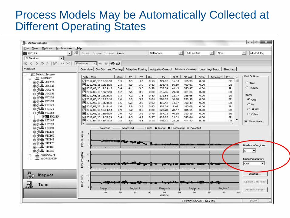
Process Models May be Automatically Collected at Different Operating States
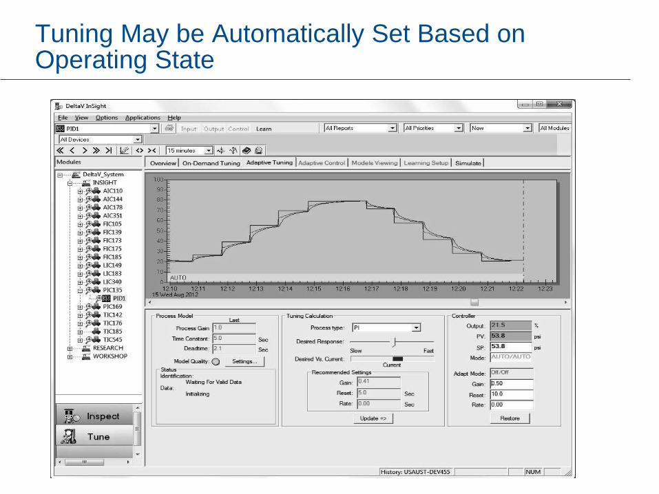
Tuning May be Automatically Set Based on Operating State
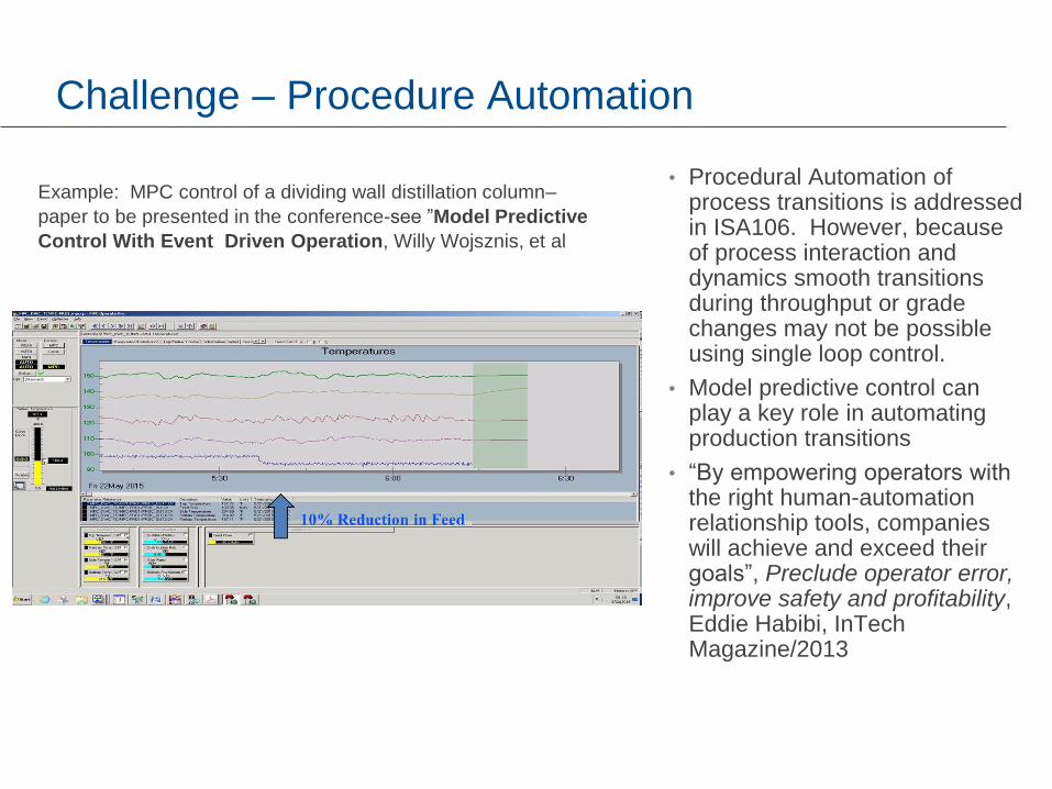
Challenge – Procedure Automation
• Procedural Automation of process transitions is addressed in ISA106. However, because of process interaction and dynamics smooth transitions during throughput or grade changes may not be possible using single loop control.
• Model predictive control can play a key role in automating production transitions
• “By empowering operators with the right human-automation relationship tools, companies will achieve and exceed their goals”, Preclude operator error, improve safety and profitability, Eddie Habibi, InTech Magazine/2013
Example: MPC control of a dividing wall distillation column–
paper to be presented in the conference-see ”Model Predictive
Control With Event Driven Operation, Willy Wojsznis, et al
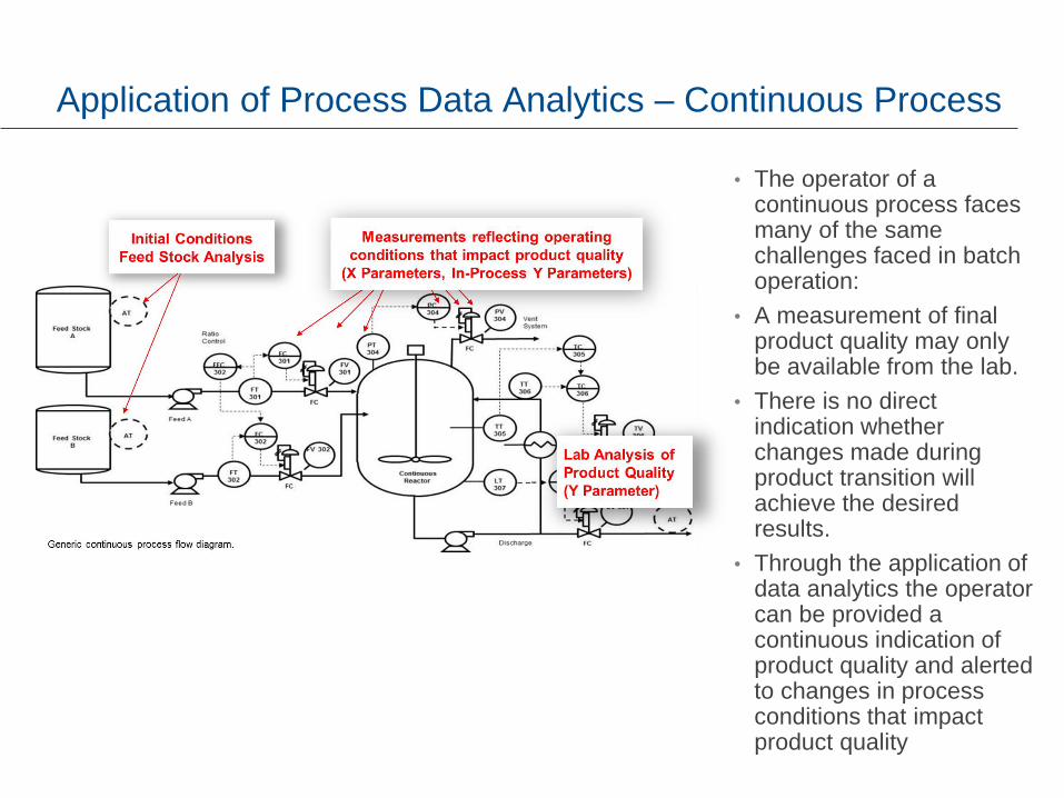
Application of Process Data Analytics – Continuous Process
• The operator of a continuous process faces many of the same challenges faced in batch operation:
• A measurement of final product quality may only be available from the lab.
• There is no direct indication whether changes made during product transition will achieve the desired results.
• Through the application of data analytics the operator can be provided a continuous indication of product quality and alerted to changes in process conditions that impact product quality

The Nature of Continuous Data
The normal operating point of process measurement may change with process throughput. The parameter(s) that drive change in the process are known as state parameters (e.g. production rate). In this example, the state parameter is the fuel demand.
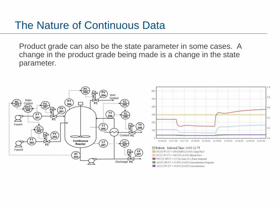
The Nature of Continuous Data
Product grade can also be the state parameter in some cases. A change in the product grade being made is a change in the state parameter.

Example: Analytics Field Trial at Lubrizol, Deer Park, TX

Quality Parameter Prediction – Continuous Process Analytics
Reference:
• Q. Li, E Hernandez, R. Wojewodka, T. Blevins, Application of On-line Data Analytics to a Continuous Process Polybutene Unit, Emerson Exchange, 2013.
• T. Blevins, W. Wojsznis, M. Nixon, Advanced Control Foundation – Tools, Techniques and Application, ISA, 2012
Compressor Efficiency Model Polybutene Unit

Technology Changes Since mid-1990’s
0
5
10
15
20
25
30
35
1995 1997 1999 2001 2003 2005 2007 2009 2011
Dynamic Memory
Cost of 1 Mbyte($)

End User Benefits of New Technology
Future control system should take advantage of changes in technology
History collection –new measure values, control actions, changes in batch data,
and alarms and events are automatically cached in the controller and efficiently
transferred to a server without the need for compression, configuration, or sub-
sampling. High fidelity, real time data will always be available without compromise.
Batch Control – All recipes will be maintained local within the controller eliminate
the burst loading and delays in communication of recipe from a server to the
controller
Advanced Control Applications – No need to configure a historian data to be able
to utilize these tools. The concept of “data always available” will become a reality.
Achieving Changes – Fast queries of data in the server may be used to determine
when changes were made during startup, shutdown and during transitions in
production.
Global Data Access –Control system stations and wireless hand held devices may
utilize applications that have access to all process data to better support
procedure automation of startup, shutdown and transition procedures. Data will
be structured in the server to support quick and easy transferred to the Cloud.
Summary
• Standards have played an important role in the automation of batch processes.
• The evolving ISA106 standard will help plants address automation of procedures for process startup, shutdown, and transitions. State-based control is an effective method for structuring procedure. Wireless instrumentation can in some cases be used to facilitate automation but manual steps will still be required in many applications. Wireless interface devices may be used to better integrate manual steps into procedures. MPC may be applied to more effectively address transitions.
• Process analytics can be applied to improve batch and continuous processing. The challenge for suppliers is to simplify the implementation and maintenance of analytics applications.
• Advances and reduction in cost of communications, controller memory, and disk storage can be used by manufacturers to create a new generation of control systems that support the concept of “data always available”.

Where To Get More Information
• T. Blevins, W. K. Wojsznis and M. Nixon, Advanced Control Foundation – Tools, Techniques,
and Applications, ISA. 2012, http://www.amazon.com/Advanced-Control-Foundation-
Techniques-Applications/dp/1937560554
• T. Blevins, D. Chen, M. Nixon, W. K. Wojsznis, Wireless Control Foundation – Continuous and
Discrete Applications, ISA 2014, http://www.amazon.com/Wireless-Control-Foundation-
Continuous-Discrete/dp/0876640889
• Y. Nazer, E. Cosman, Process Automation at Dow Unit Based Control (UBC), ARC Forum,
Orlando, Florida, 2010, http://www.arcweb.com/events/arc-industry-forum-
orlando/orlandoforum2010presentations/Unit%20Based%20Control.pdf
• ISA106, Procedure Automation for Continuous Process Operations- ISA,
https://www.isa.org/isa106/
• B. Scholten, Integrating ISA-88 and ISA-95, ISA EXPO 2007, 2-4 October 2007, Reliant
Center, Houston, Texas, https://www.isa.org

Questions

Thank You for Attending!
Enjoy the rest of the conference.