automatic fault detection and location in power transmission lines
TRANSCRIPT

193 | P a g e
AUTOMATIC FAULT DETECTION AND LOCATION
IN POWER TRANSMISSION LINES USING GSM
TECHNOLOGY
Ing. Komi Agbesi1, Felix Attuquaye Okai
2
1,2Department of Computer Science, Accra Polytechnic, (Ghana)
ABSTRACT
Many electricity transmission companies across the world and Ghana in particular are continuously looking for
ways to utilise modern technologies, in order to improve reliability of power supply to consumers. These
transmission companies manly relies on circuit indicators (FCIs) to assist in locating specific spots within their
transmission lines where power fault had occured.
In this paper, a smart GSM based fault detection and location system was used to adequatly and accurately
indicate and locate the exact spot where fault had occured. This will ensure a shorter response time for
technical crew to rectify these faults and thus help save transformers from damage and disasters. The system
uses a current transformer, a voltage transformer, PIC 16F877 Microcontroller, RS-232 connector, and a GSM
modem. The system automatically detects faults, analyses and classifies these faults and then, calculates the
fault distance from the control room using an impedance-based algorithm method. Finally the fault information
is transmitted to the control room. In conclusion, the time required to locate a fault is drastically reduced, as the
system automatically and accurately provides accurate fault location information.
Keywords: GSM modem, impedance-based algorithm, Microcontroller, RS-232 Connector, Voltage
Transformer
I. INTRODUCTION
Many electric power transmission companies such as Ghana Grid Company limited ( GRIDco ) in Ghana, have
primarily relied on circuit indicators to detect faulty sections of their transmission lines. However there are still
challenges in detecting the exact location of these faults. Although fault indicator technology has provided a
reliable means to locate permanent faults, the technical crew and patrol teams still has to physically patrol and
inspect the devices for longer hours to detect faulty sections of their transmission lines.
1.1 Problem Statement
To reduce the duration of outages and minimise response time to major faults, and to optimise reliabilty of
supply, it is inevitable for power transmission companies such as GRIDco to search for a low-cost
communicating device with low power consumption that will relay accurate fault information at real-time back
to the control centre.
194 | P a g e
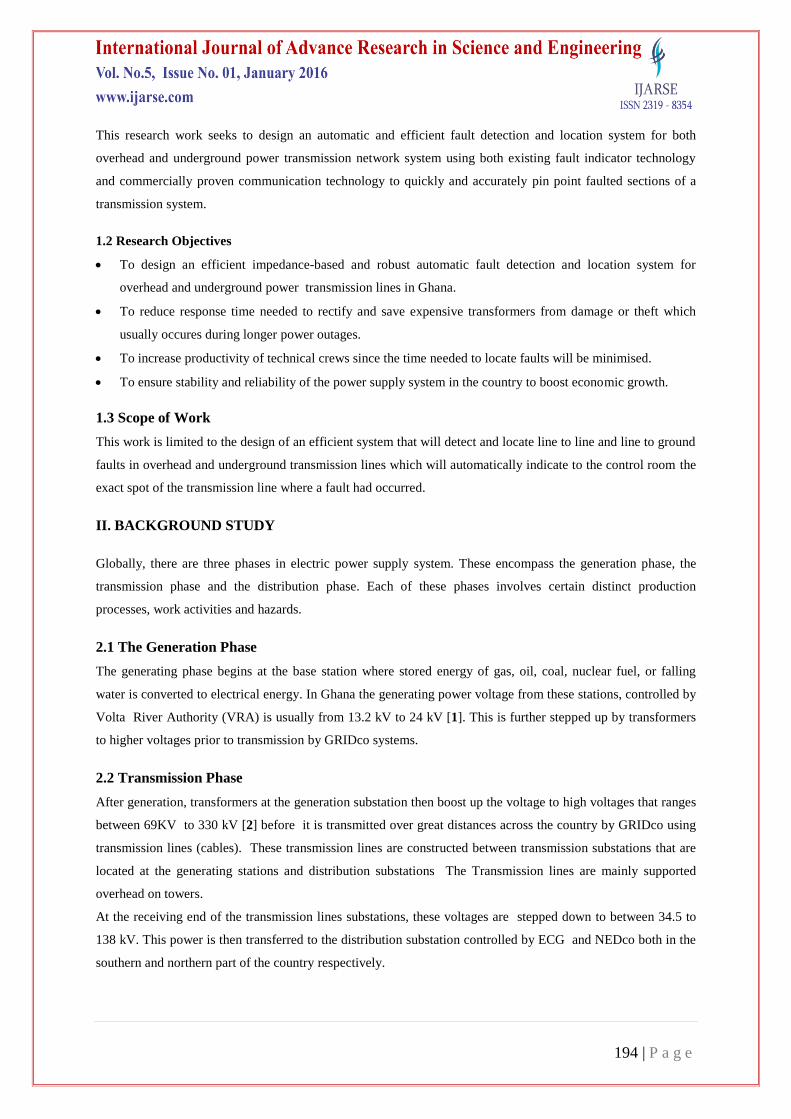
This research work seeks to design an automatic and efficient fault detection and location system for both
overhead and underground power transmission network system using both existing fault indicator technology
and commercially proven communication technology to quickly and accurately pin point faulted sections of a
transmission system.
1.2 Research Objectives
To design an efficient impedance-based and robust automatic fault detection and location system for
overhead and underground power transmission lines in Ghana.
To reduce response time needed to rectify and save expensive transformers from damage or theft which
usually occures during longer power outages.
To increase productivity of technical crews since the time needed to locate faults will be minimised.
To ensure stability and reliability of the power supply system in the country to boost economic growth.
1.3 Scope of Work
This work is limited to the design of an efficient system that will detect and locate line to line and line to ground
faults in overhead and underground transmission lines which will automatically indicate to the control room the
exact spot of the transmission line where a fault had occurred.
II. BACKGROUND STUDY
Globally, there are three phases in electric power supply system. These encompass the generation phase, the
transmission phase and the distribution phase. Each of these phases involves certain distinct production
processes, work activities and hazards.
2.1 The Generation Phase
The generating phase begins at the base station where stored energy of gas, oil, coal, nuclear fuel, or falling
water is converted to electrical energy. In Ghana the generating power voltage from these stations, controlled by
Volta River Authority (VRA) is usually from 13.2 kV to 24 kV [1]. This is further stepped up by transformers
to higher voltages prior to transmission by GRIDco systems.
2.2 Transmission Phase
After generation, transformers at the generation substation then boost up the voltage to high voltages that ranges
between 69KV to 330 kV [2] before it is transmitted over great distances across the country by GRIDco using
transmission lines (cables). These transmission lines are constructed between transmission substations that are
located at the generating stations and distribution substations The Transmission lines are mainly supported
overhead on towers.
At the receiving end of the transmission lines substations, these voltages are stepped down to between 34.5 to
138 kV. This power is then transferred to the distribution substation controlled by ECG and NEDco both in the
southern and northern part of the country respectively.

195 | P a g e
2.3 Distribution Phase
As stated above, the distribution phase ( controlled by ECG and NEDco) connects the transmission system of
GRIDco to the customer’s equipment. The distribution substation reduces the transmitted electrical voltage from
161KV, to 24 kV. A distribution transformer further reduces the voltage to 240V, which is the standard voltage
recommended in Ghana.
Transmission and distribution substations are installations where the voltage, phase or other characteristics of
the electrical energy are changed as part of the final distribution process [3].
Fig 1 depicts the stages and the stakeholders responsible for power generation, transmission and to distribution
for consumers in Ghana.
Figure 1: Generation, Transmission and Distribution of Power ( Source: Ghana power
reliability report 2010)
2.4 Ghana Transmission Grid
Ghana electrical transmission system is very complex and dynamic than other utility systems, such as water.
Energy produced from the generating stations in Ghana is transmitted to GRIDco power sale customers through
an interconnected transmission network at 69, 161, 225kV and 330KV voltage levels [4].
The existing transmission network comprises of: [5]
A 161kV closed loop grid serving the concentrated load centres of the southern part of Ghana and a long161kV
direct line from Kumasi to the relatively lightly loaded northern parts of Ghana where electricity penetration is
low. Also a 161kV radial line from Techiman to Sawla in the north-western part of the country, extends to Wa,
in the Upper West Region at 34.5kV. A single circuit 225kV 220km transmission line between Prestea
substation in the Western part of Ghana and Abobo substation, located near Abidjan in Cote d'Ivoire.
A double circuit 161kV line connecting the Akosombo Generating Plant in Ghana to Lome substation in Togo,
to supply power to both Togo and Benin
196 | P a g e
In all there are 66 substations that either serve as switching stations with no power transformers (Volta), step-up
stations for the generation plants and/or step-down stations that step down the high voltages to various medium
voltages (34.5kV, 11.5kV, 6.6kV) with total installed transformer capacity of 2,630MVA, meant for the
distribution system.
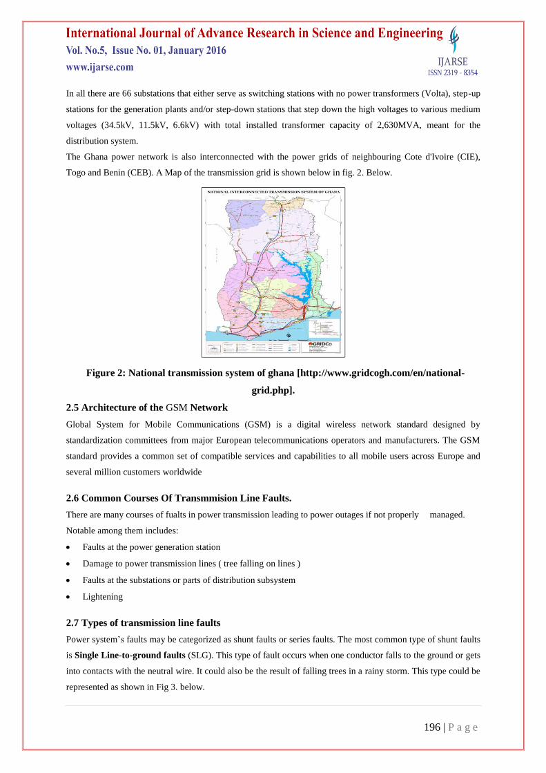
The Ghana power network is also interconnected with the power grids of neighbouring Cote d'Ivoire (CIE),
Togo and Benin (CEB). A Map of the transmission grid is shown below in fig. 2. Below.
Figure 2: National transmission system of ghana [http://www.gridcogh.com/en/national-
grid.php].
2.5 Architecture of the GSM Network
Global System for Mobile Communications (GSM) is a digital wireless network standard designed by
standardization committees from major European telecommunications operators and manufacturers. The GSM
standard provides a common set of compatible services and capabilities to all mobile users across Europe and
several million customers worldwide
2.6 Common Courses Of Transmmision Line Faults.
There are many courses of fualts in power transmission leading to power outages if not properly managed.
Notable among them includes:
Faults at the power generation station
Damage to power transmission lines ( tree falling on lines )
Faults at the substations or parts of distribution subsystem
Lightening
2.7 Types of transmission line faults
Power system’s faults may be categorized as shunt faults or series faults. The most common type of shunt faults
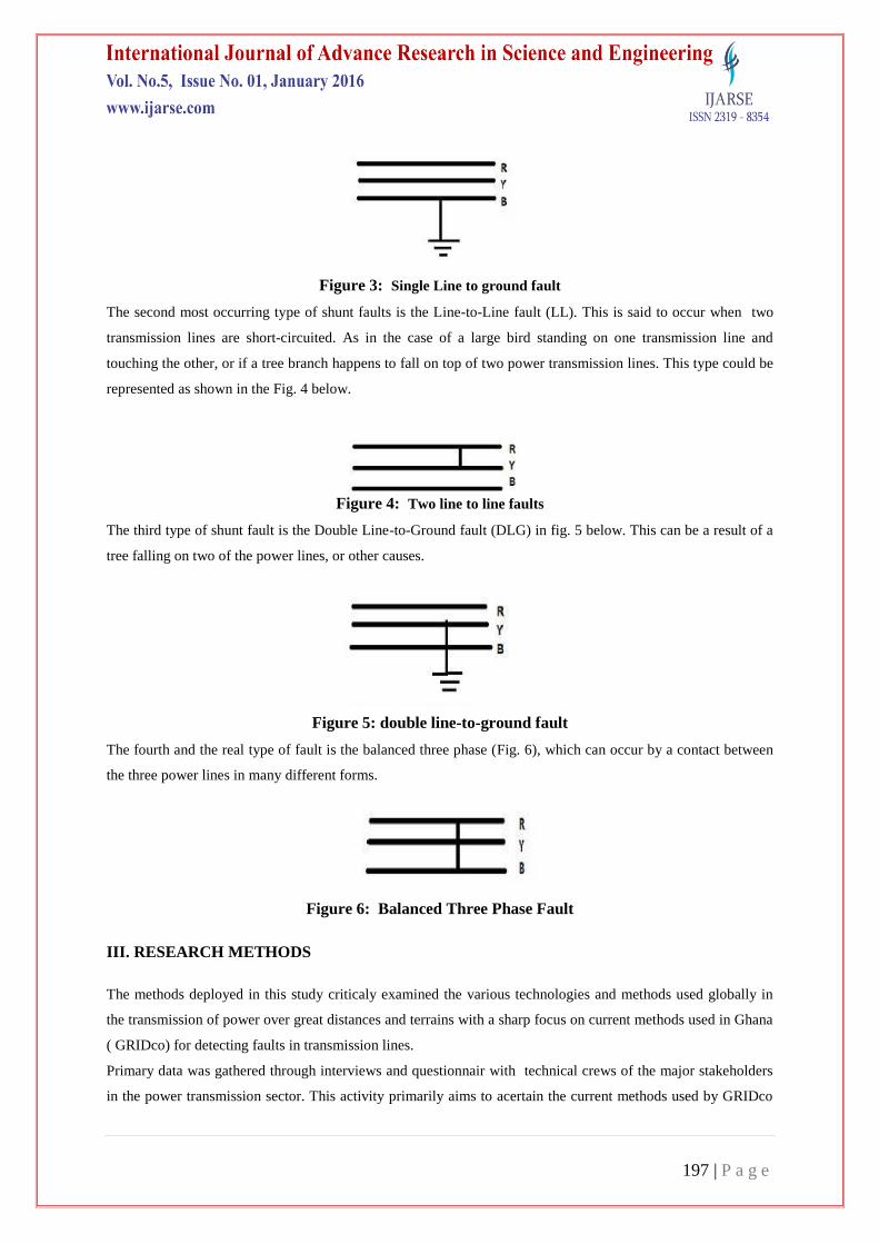
is Single Line-to-ground faults (SLG). This type of fault occurs when one conductor falls to the ground or gets
into contacts with the neutral wire. It could also be the result of falling trees in a rainy storm. This type could be
represented as shown in Fig 3. below.
197 | P a g e
Figure 3: Single Line to ground fault
The second most occurring type of shunt faults is the Line-to-Line fault (LL). This is said to occur when two
transmission lines are short-circuited. As in the case of a large bird standing on one transmission line and
touching the other, or if a tree branch happens to fall on top of two power transmission lines. This type could be
represented as shown in the Fig. 4 below.
Figure 4: Two line to line faults
The third type of shunt fault is the Double Line-to-Ground fault (DLG) in fig. 5 below. This can be a result of a
tree falling on two of the power lines, or other causes.
Figure 5: double line-to-ground fault
The fourth and the real type of fault is the balanced three phase (Fig. 6), which can occur by a contact between
the three power lines in many different forms.
Figure 6: Balanced Three Phase Fault
III. RESEARCH METHODS
The methods deployed in this study criticaly examined the various technologies and methods used globally in
the transmission of power over great distances and terrains with a sharp focus on current methods used in Ghana
( GRIDco) for detecting faults in transmission lines.
Primary data was gathered through interviews and questionnair with technical crews of the major stakeholders
in the power transmission sector. This activity primarily aims to acertain the current methods used by GRIDco
198 | P a g e
who is solely responseble for bulk tranmission of power throughout Ghana and beyond, for detecting faults in
their transmission lines.
Secondary data was also aquired from official websites of GRIDco, Volta River Autority (VRA) and Electricity
Company of Ghan (ECG).
3.1 Stakeholders Analysis:
In all three (3) main stake holders were identified and contacted for information on how transmission faults are
detected and fixed. These companies includes
i) Volta River Authority (VRA), ( Solely responsible for the generation of power in Ghana using termal,
hydro, Solar and other renewable materials for power generation).
ii) Ghana Grid Company Limited ( GRIDco), ( solely responsible for the transmission of electrical power
from the generation station to the various destribution substations across the lengh and breadth of the
country and even beyond the borders of Ghana to the neighboring countries). This includes cote de
voire on the west, Togo on the eastern corridor, through to Benin and to the western parts of Nigeria.
iii) Electricity Company of Ghana ( ECG ) and Northern Electricity Distribution Company (NEDco)
(responsible for bulk distribution of power to commercial and domestic consumers at the southern and
northern part of the country respectively..
The major stakeholder and the main focus for data acquisition in this study was GRIDco, because they are sole
unboundled bulk power transmission supplier in Ghana and henced received a bulk of the questionnairs and
interviews
A total of 30 questionnairs were distributed to different groups of workers within the major stackholder (
GRIDco ) as mentioned above. However out of a total of 30 questionnairs distributed, 26 were returned due to
follow-ups from the researcher. These figure constituted 86.6% response rate.
Again interviews were also granted to three (3) local operational managers.of GRIDco ( Systems operations
manager, network operations manager and local supervisor for operations).
The questionnairs and interviews seeks to enquire among other things but not limited to the following questions:
i. The major causes of transmission line faults in all GRIDco’s network
ii. How these faults are detected and located.
iii. The socio-economic refects of these transmission outages
Results from the questionnairs analysis indicated that eventhough the system used by GRIDco to detect fault on
its transmission lines is equiped with an automatic fault detection system, this can only detect line to earth
faults. After detection, the system automatically cuts off supply to the faulted line and indicate to the control
room that a fault had occurred. But however the system lacks the ability to automatically detect the exact spot
that the fault had occurred along the transmission line
The usual practice after a fault had ben detected is to manually inspect the entire suspected faulted line by
response crew until the fault is located. This takes the team a consederable amount of time especially when the
line traverses through forested regions and rough terrains. Again due to the ongoing rural electrification projects
embacked upon by the government of Ghana, most of these transmission lines runs through forested and
unaccessible terains that makes it very difficult for the technical crew to locate and reach the faulted spot. This
199 | P a g e
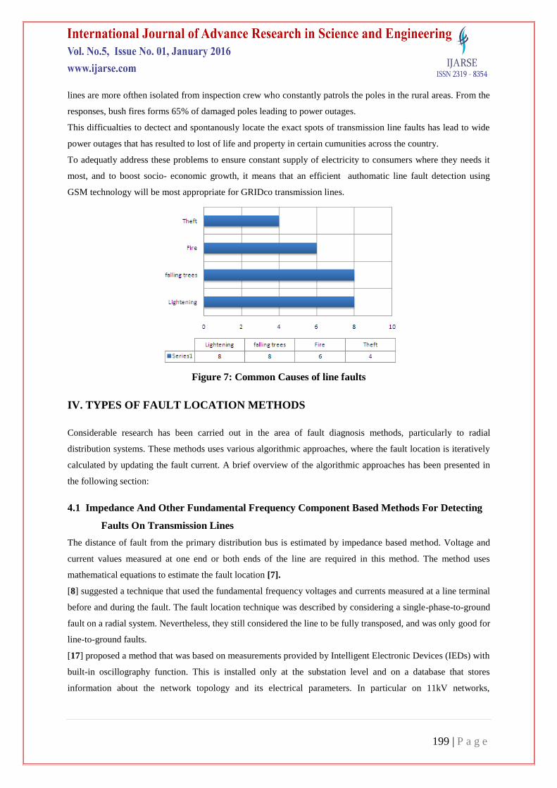
lines are more ofthen isolated from inspection crew who constantly patrols the poles in the rural areas. From the
responses, bush fires forms 65% of damaged poles leading to power outages.
This difficualties to dectect and spontanously locate the exact spots of transmission line faults has lead to wide
power outages that has resulted to lost of life and property in certain cumunities across the country.
To adequatly address these problems to ensure constant supply of electricity to consumers where they needs it
most, and to boost socio- economic growth, it means that an efficient authomatic line fault detection using
GSM technology will be most appropriate for GRIDco transmission lines.
Figure 7: Common Causes of line faults
IV. TYPES OF FAULT LOCATION METHODS
Considerable research has been carried out in the area of fault diagnosis methods, particularly to radial
distribution systems. These methods uses various algorithmic approaches, where the fault location is iteratively
calculated by updating the fault current. A brief overview of the algorithmic approaches has been presented in
the following section:
4.1 Impedance And Other Fundamental Frequency Component Based Methods For Detecting
Faults On Transmission Lines
The distance of fault from the primary distribution bus is estimated by impedance based method. Voltage and
current values measured at one end or both ends of the line are required in this method. The method uses
mathematical equations to estimate the fault location [7].
[8] suggested a technique that used the fundamental frequency voltages and currents measured at a line terminal
before and during the fault. The fault location technique was described by considering a single-phase-to-ground
fault on a radial system. Nevertheless, they still considered the line to be fully transposed, and was only good for
line-to-ground faults.
[17] proposed a method that was based on measurements provided by Intelligent Electronic Devices (IEDs) with
built-in oscillography function. This is installed only at the substation level and on a database that stores
information about the network topology and its electrical parameters. In particular on 11kV networks,

200 | P a g e
application of the method was a problem. It was difficult to obtain reliable statistical estimates, and also time
consuming due to iterative process and need to know the fault type before specific equation could be applied.
4.2 High Frequency Components and Travelling Wave Based Methods
This method was generally based on the reflection and transmission of the fault generated by travelling waves
on the faulted power network. Although in this technique fault can be located with high accuracy, the
implementation is complex and more expensive than the implementation of impedance based techniques. This is
because it needs too many added equipment such as the GPS system, fault transient detectors and diagnostic
software. Furthermore, due to the complex configurations of distribution systems, the configuration or the sites
to install the fault transient detectors become very difficult.
4.3 Knowledge-Based Method
The third category is knowledge-based method. This method can be divided into three groups:
a. Artificial intelligence and statistical analysis based methods
b. Distributed device based methods
c. Hybrid methods
4.4 Artificial Intelligence (AI) and Statistical Analysis Based Methods
There are several artificial intelligent methods such as Artificial Neural network (ANN), Fuzzy Logic (FL),
Expert System (ES) and Genetic Algorithm (GA). These methods can help operators or engineers to do much
laborious work. By using these methods, the time factor is substantially reduced and human mistakes are
avoided. Therefore, many researchers used AI based methods in transmission system fault locations.
[9] developed a fault location method for multi-ring distribution systems using neural network. They used the
feeder fault voltage, circuit breaker status, real power of feeders during the normal condition, and real power of
feeders during short circuit, etc, to train the neural network.
4.5 Distributed Device Based Methods
Another type of knowledge-based technique is distributed device based methods for locating fault. [10]
presented a mathematical approach that located faults based on installed voltage sensors’ information and the
network’s topological structure. The relation of the voltage sensors with sections was formulated as a matrix.
The other matrix was constructed based on the topological relation between sections and nodes in an electric
network. Through some matrix operations, all faulted sections could be found.
4.6 Hybrid Methods
Almost all of the above methods locate faults based on one algorithm, such as the fault distance calculation or
operated protective device’s status analysis. Some have investigated the use of hybrid methods that locate faults
based on more than one algorithm to achieve a more accurate estimation of the faulted section.
11]proposed a hybrid method that computed the fault distance using measurements available at the substation.
They used post-fault values of current or voltage to reduce the multiple estimation problems induced by the
existence of multiple fault points in the network. To identify the actual fault location, a fault diagnosis procedure
was applied to rank the list of multiple potential fault locations. By doing a circuit simulation, the operation of a
201 | P a g e
particular combination of protective devices and the load change pattern during different fault scenarios could
be obtained. Then by matching the fault situation to these scenarios, the actual faulted section could be
determined.
V. COMPONENTS FOR THE PROPOSED (New) SYSTEM
This section highlights the state-of- the art devices that will be needed to implement the system. These devices
will provide the much needed attributes for the new system: robustness, low cost, efficiency, accuracy and low
power.
5.1 Microcontroller
A microcontroller (MCU) is a small computer on a single integrated circuit (IC) containing a processor core,
memory, and programmable input/output peripherals. Program memory is also often included on the chip, as
well as a typically small amount of RAM. Microcontrollers are designed for embedded applications, in contrast
to the microprocessors used in personal computers or other general purpose applications.
Microcontrollers are used in automatically controlled products and devices, such as automobile engine control
systems, implantable medical devices, remote controls, office machines, appliances, and power tools [12].
5.2 The PIC16F877 Microcontroller
Programmable Intelligent Computer (PIC) is a family of Harvard architecture microcontrollers made by
Microchip Technology, derived from the PIC1640 originally developed by General Instrument’s
Microelectronics Division.
The PIC16F877 falls in the mid-range of the PIC family of microcontrollers and finds use in a wide range of
applications in diverse fields due to the fact that it is readily available. It also has a large number of pins (40
pins) with a maximum of three functions per pin which makes it much easier to use as compared to others with
limited pins and a high number of functions per pin. It also has an optimal cost-to-performance ratio.
The above mentioned desirable characteristic of the PIC16F877 microcontroller coupled with the fact that it has
an in-built Analog to Digital Converter and sufficient program memory to store the control algorithm, have
largely affected its choice for the design of the automatic fault detection and location system discussed in this
work.
5.2.1 PIC16F877 Microcontroller Architecture
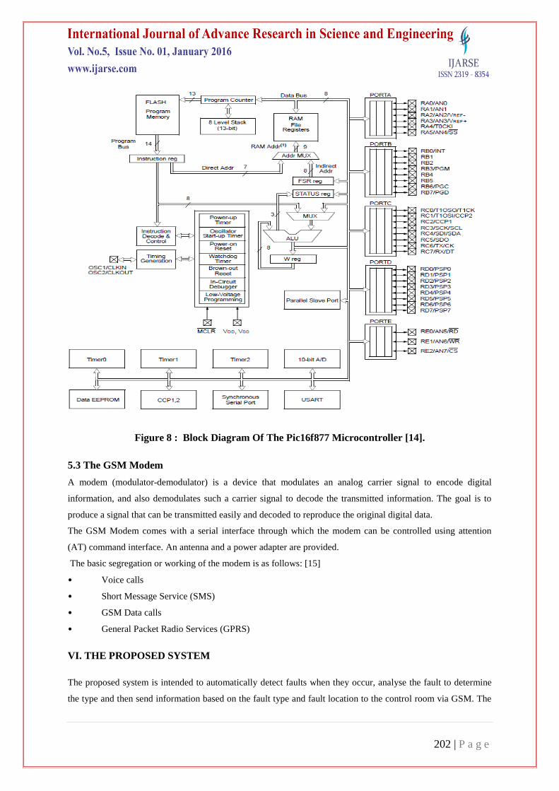
The key features of the PIC16F877 microcontroller are summarily presented with the block diagram in Fig. 8
below.
202 | P a g e
Figure 8 : Block Diagram Of The Pic16f877 Microcontroller [14].
5.3 The GSM Modem
A modem (modulator-demodulator) is a device that modulates an analog carrier signal to encode digital
information, and also demodulates such a carrier signal to decode the transmitted information. The goal is to
produce a signal that can be transmitted easily and decoded to reproduce the original digital data.
The GSM Modem comes with a serial interface through which the modem can be controlled using attention
(AT) command interface. An antenna and a power adapter are provided.
The basic segregation or working of the modem is as follows: [15]
• Voice calls
• Short Message Service (SMS)
• GSM Data calls
• General Packet Radio Services (GPRS)
VI. THE PROPOSED SYSTEM
The proposed system is intended to automatically detect faults when they occur, analyse the fault to determine
the type and then send information based on the fault type and fault location to the control room via GSM. The

203 | P a g e
device location is determined by the SIM card in the modem, each SIM card having a unique identification and
hence is used as the device’s address.
The system senses, analyses and transmits. It does this with the microcontroller which analyses, interprets and
sends digital signals to the I/O devices for the system to operate. By programming, the microcontroller is made
to perform these functions.
6.1 System Hardware
The automatic fault detection and location system comprises of a current transformer, a voltage transformer, a
microcontroller, an RS-232 connector and a GSM modem as shown in the block diagram in Fig. 9.
Figure 9: Block Diagram of Proposed Fault Detection and Location System
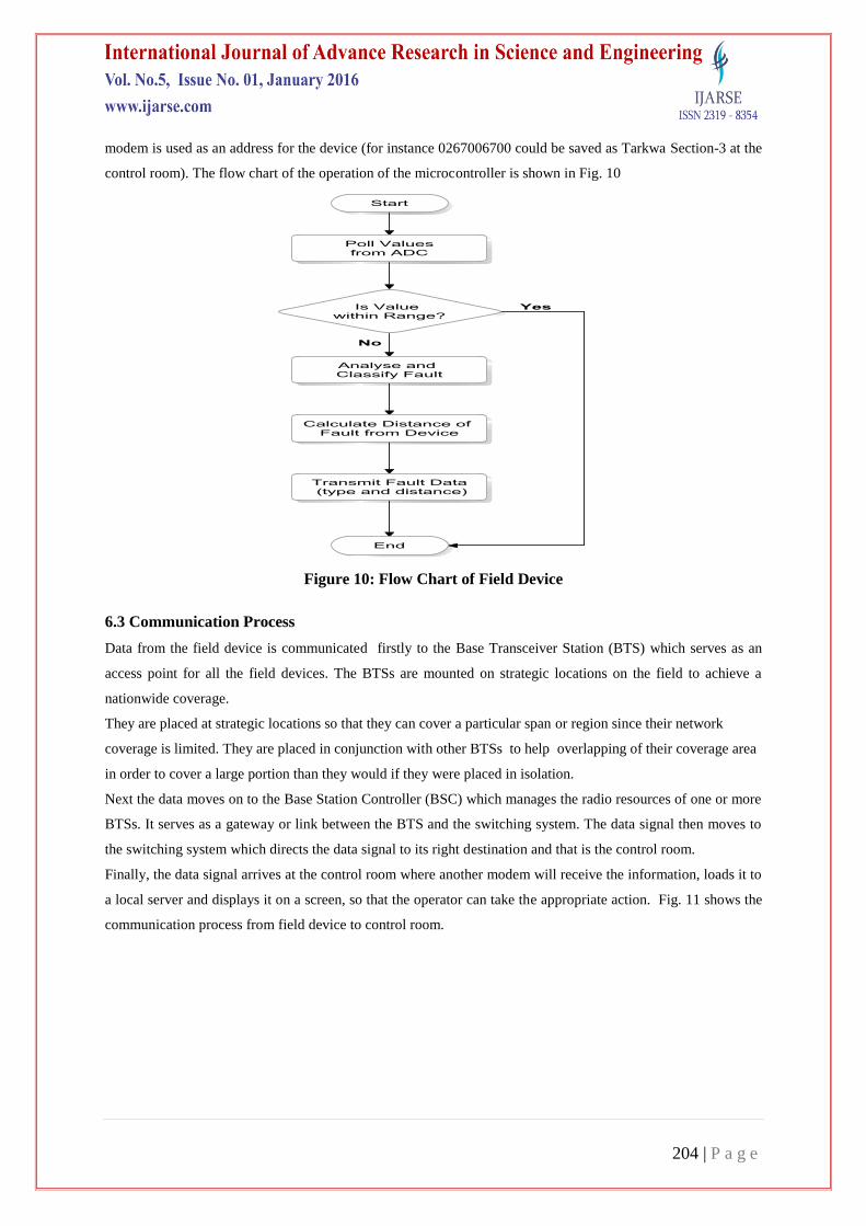
6.2 Mode of Operation
The set up or field device consists of 3 major components, instrument transformer (CT and VT), GSM modem
and microcontroller. The primaries of the CT and VT which are connected to the line sense the corresponding
current and voltage values of the system and feed the output to the ADC of the microcontroller which converts
the signal to a digital form in order to be processed by the CPU of the microcontroller.
The microcontroller serves as the central point of the set up. It contains a set of programming codes which have
been stored in the EEPROM which enables it to classify the fault type based on the voltage and current values.
Based on the program, the microcontroller compares these values to see whether they are within the range
required. If the voltage and current values are out of range as compared to the reference, it gives an indication of
a fault.
The microcontroller also calculates the fault distance, relative to the device based on an impedance-based
algorithm and then relays this information to the modem for transmission. In summary, the microcontroller
classifies, calculates the fault distance and relays the information to the modem for transmission via the serial
communication interface (SCI) which serves as an interface between the microcontroller and the modem. The
RS-232 serves as the connector between the microcontroller’s serial communication port and the modem.
The device is placed in the boundary of the sectionalised regions in the transmission system and the location of
the fault is calculated relative to the position of the device. The unique identity of the SIM card in the GSM
204 | P a g e
modem is used as an address for the device (for instance 0267006700 could be saved as Tarkwa Section-3 at the
control room). The flow chart of the operation of the microcontroller is shown in Fig. 10
Figure 10: Flow Chart of Field Device
6.3 Communication Process
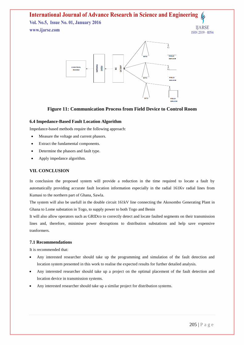
Data from the field device is communicated firstly to the Base Transceiver Station (BTS) which serves as an
access point for all the field devices. The BTSs are mounted on strategic locations on the field to achieve a
nationwide coverage.
They are placed at strategic locations so that they can cover a particular span or region since their network
coverage is limited. They are placed in conjunction with other BTSs to help overlapping of their coverage area
in order to cover a large portion than they would if they were placed in isolation.
Next the data moves on to the Base Station Controller (BSC) which manages the radio resources of one or more
BTSs. It serves as a gateway or link between the BTS and the switching system. The data signal then moves to
the switching system which directs the data signal to its right destination and that is the control room.
Finally, the data signal arrives at the control room where another modem will receive the information, loads it to
a local server and displays it on a screen, so that the operator can take the appropriate action. Fig. 11 shows the
communication process from field device to control room.
205 | P a g e
Figure 11: Communication Process from Field Device to Control Room
6.4 Impedance-Based Fault Location Algorithm
Impedance-based methods require the following approach:
Measure the voltage and current phasors.
Extract the fundamental components.
Determine the phasors and fault type.
Apply impedance algorithm.
VII. CONCLUSION
In conclusion the proposed system will provide a reduction in the time required to locate a fault by
automatically providing accurate fault location information especially in the radial 161Kv radial lines from
Kumasi to the northern part of Ghana, Sawla.
The system will also be usefull in the double circuit 161kV line connecting the Akosombo Generating Plant in
Ghana to Lome substation in Togo, to supply power to both Togo and Benin
It will also allow operators such as GRIDco to correctly detect and locate faulted segments on their transmission
lines and, therefore, minimise power desruptions to distribution substations and help save expensive
tranformers.
7.1 Recommendations
It is recommended that:
Any interested researcher should take up the programming and simulation of the fault detection and
location system presented in this work to realise the expected results for further detailed analysis.
Any interested researcher should take up a project on the optimal placement of the fault detection and
location device in transmission systems.
Any interested researcher should take up a similar project for distribution systems.
206 | P a g e
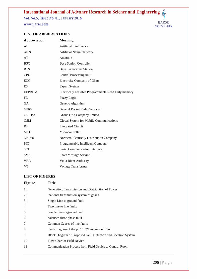
LIST OF ABBREVIATIONS
Abbreviation Meaning
AI Artificial Intelligence
ANN Artificial Neural network
AT Attention
BSC Base Station Controller
BTS Base Transceiver Station
CPU Central Processing unit
ECG Electricity Company of Ghan
ES Expert System
EEPROM Electricaly Erasable Programmable Read Only memory
FL Fuzzy Logic
GA Genetic Algorithm
GPRS General Packet Radio Services
GRIDco Ghana Grid Company limited
GSM Global System for Mobile Communications
IC Integrated Circuit
MCU Microcontroller
NEDco Northern Electricity Distribution Company
PIC Programmable Intelligent Computer
SCI Serial Communication Interface
SMS Short Message Service
VRA Volta River Authority
VT Voltage Transformer
LIST OF FIGURES
Figure Title
1: Generation, Transmission and Distribution of Power
2 : national transmission system of ghana
3: Single Line to ground fault
4 Two line to line faults
5 double line-to-ground fault
6 balanced three phase fault
7 Common Causes of line faults
8 block diagram of the pic16f877 microcontroller
9 Block Diagram of Proposed Fault Detection and Location System
10 Flow Chart of Field Device
11 Communication Process from Field Device to Control Room

207 | P a g e
REFERENCES
[1] http://www.gridcogh.com/en/press-media/gridco-reliability-assessment-report.php
[2] Anon, (2009a) Electric Transmission Lines
[3] Anon, (2010) Generation Transmission Distribution
[4] Power Systems Energy Consulting, Ghana Power Reliability Report , 2010.
http://www.gridcogh.com/en/national-grid.php pp. 16
[5] Power Systems Energy Consulting, Ghana Power Reliability Report , 2010.
http://www.gridcogh.com/en/national-grid.php
[6] Power Systems Energy Consulting, Ghana Power Reliability Report , 2010.
http://www.gridcogh.com/en/national-grid.php
[7] Senger, E. C., Manassero, G., Goldemberg, C. and Pellini, E. L. (2005), Automated Fault Location
System for Primary Distribution Networks, IEEE Transactions on Power Delivery, pp. 1332-1340.
[8] Das R., Sachdev, M. S. and Sidhu, T. S. (2000), A Fault Locator for Radial Sub Transmission and
Distribution Lines”, In Proceedings of IEEE PES Summer Meeting, pp. 443-448.
[9] Senger, E. C., Manassero, G., Goldemberg, C. and Pellini, E. L. (2005), Automated Fault Location
System for Primary Distribution Networks, IEEE Transactions on Power Delivery, pp. 1332-1340.
[10] Al-Shaher, M., Sabra, M. M. and Saleh, A.S. (2003), Fault Location in Multi-Ring Distribution Network
using Artificial Neural Network, Electric Power Systems Research. pp. 87-92.
[11] Wang, C., Nouri, H. and Davies, T. S. (2000), A Mathematical Approach for Identification of Fault
Sections on the Radial Distribution Systems, 10 Mediterranean Electrotechnical Conference
(MELECON), pp. 882-886.
[12] Zhu, J., Lubkerman, D. L. and Girgis, A. A. (1997), Automated Fault Location and Diagnosis on Electric
Power Distribution Feeders, IEEE Trans on Power Delivery, pp. 801-809.
[13] Anon, Microcontroller (2009b)
[14] Anon, PIC16F87X Data Sheet, Microchip Technology Inc., USA, (2001) 216 pp
[15] Raviraj, T., Technical Introduction to GSM Modem Technology(2007)
[16] Kabir, M., Cellular Mobile Systems and Services(2009)