automatic system for utility electrical fault (fault
TRANSCRIPT

AUTOMATIC SYSTEM FOR UTILITY ELECTRICAL FAULT
(FAULT LOCATION DETECTION USING LabVIEW)
by
MOHD FIRDAUS BIN NOORDIN
Dissertation submitted in partial fulfilment of
the requirements for the
Bachelor of Engineering (Hons)
(Electrical and Electronics Engineering)
DECEMBER 2010
Universiti Teknologi PETRONAS
Bandar Seri Iskandar
31750 Tronoh
Perak Darul Ridzuan

i
CERTIFICATION OF APPROVAL
by
Mohd Firdaus Bin Noordin
A project dissertation submitted to the
Electrical and Electronics Engineering Programme
Universiti Teknologi PETRONAS
in partial fulfilment of the requirement for the
BACHELOR OF ENGINEERING (Hons)
(ELECTRICAL AND ELECTRONICS ENGINEERING)
Approved by,
__________________________
(Dr. Nursyarizal bin Mohd Nor)
Project Supervisor
UNIVERSITI TEKNOLOGI PETRONAS
TRONOH, PERAK
DECEMBER 2010

ii
CERTIFICATION OF ORIGINALITY
This is to certify that I am responsible for the work submitted in this project, that the
original work is my own except as specified in the references and that the original
work contained herein have not been undertaken or done by unspecified sources or
persons.
______________________________
MOHD FIRDAUS BIN NOORDIN

iii
ABSTRACT
Continuous supply of electricity to domestic building is a major concern for
the consumers. The consumers need a continuous electricity supply to their
appliances such as refrigerator, aquarium and their alarm system. Tripping of earth
leakage circuit breaker (ELCB) will break the supply to all the appliances. An
automatic system to restore the supply to the appliances by turn on back the ELCB is
required. But when there is a permanent fault in the system, the ELCB cannot be
turned on back to normal because it will trip again due to the fault. So the objective
of the project is to develop a system to detect the location of permanent fault. The
location of the fault is important to be determined in a first place in order to isolate
the fault from the system. So the ELCB can be reclosed back to normal position to let
the appliances have the electricity supply. Software called LabVIEW is used to
develop the system that can detect the location of permanent fault in a domestic
electrical wiring system. The idea is when the location of fault is determined, an
automatic system to isolate the Miniature Circuit Breaker (MCB) that has fault can
be developed. So when the MCB that has fault has been isolated, the ELCB can be
turned on without tripping again. The system that has been developed using
LabVIEW will compare the value of current at live wire and the value of current at
neutral wire. If the difference is more than preset value, the system will show the
detection in the front panel of the software. So the location of fault is determined.

iv
ACKNOWLEDGEMENT
First of all, I would like to express my gratitude to God for giving me the
strength and health to do this project. Not forgotten to my mother and all my family
members for providing everything, such as money and advises, which is most needed
in this project.
I would like to thank my supervisor, Dr Nursyarizal bin Mohd Nor for
sharing his knowledge and giving me the support and guidance throughout the
project. I also would like to thank my co-supervisor, Mr Saiful Azrin bin Mohd
Zulkifli for assisting me to design the software of the project.
My appreciation to Universiti Teknologi PETRONAS especially Electrical
and Electronics Engineering Department, by providing me the necessary assets and
resources, not only to accomplish my task, but to enrich my knowledge further.
Last but not least, I offer my regards to those who support me especially all
my friends and technicians in Electrical and Electronics Department for contributing
their assistance and ideas for this project.

v
TABLE OF CONTENT
CERTIFICATION OF APPROVAL...........................................................
i
CERTIFICATION OF ORIGINALITY......................................................
ii
ABSTRACT....................................................................................................
iii
ACKNOWLEDGEMENTS………………………………………………...
iv
LIST OF FIGURES.......................................................................................
vii
CHAPTER 1: INTRODUCTION
1.1 Background of Study………………………………...
1.2 Problem Statement…………………………………...
1.3 Objectives and Scope of Study ….………………….
1
1
2
CHAPTER 2: LITERATURE REVIEW
2.1 Circuit breaker …………………………………….…
2.2 Earth Leakage Circuit Breaker (ELCB)……………...
2.3 Residual Current Device (RCD)………………...…...
2.4 Miniature circuit breaker (MCB)………………..…...
2.4 Current Transducer …………..……………………...
2.5 LabVIEW ………………………………….………..
3
4
5
6
7
8
CHAPTER 3: METHODOLOGY
3.1 Procedure Identification……………………………...
3.2 Tolls and Equipments required...................................
11
13

vi
CHAPTER 4: RESULTS AND DISCUSSION
4.1 Earth Leakage Circuit Breaker (ELCB ) and
Miniature Circuit Breaker(MCB)……………………
4.2 Example of fault current calculation (ground fault)…
4.3 LabVIEW Block Diagram and Front Panel …………
4.3.1 Data Acquisition ………………………...……….
4.3.2 Data Comparison and Fault Detection ……….
14
15
18
19
21
CHAPTER 5: CONCLUSION AND RECOMMENDATIONS
5.1 Conclusion…………………………………………...
5.2 Recommendation…………………………………….
25
26
REFERENCES...............................................................................................
27
APPENDICES...............................................................................................
APPENDIX A GANTT CHART…………………………….
APPENDIX B CURRENT TRANSDUCER DATASHEET..
APPENDIX C CONNECTOR BLOCK DATASHEET……..
29
30
34

vii
LIST OF FIGURES
Figure 1: Earth Leakage Circuit Breaker.........................................................
4
Figure 2: Tripping Mechanism of RCD...........................................................
6
Figure 3: Current Transducer...........................................................................
8
Figure 4: LabVIEW Front Panel......................................................................
10
Figure 5: LabVIEW Block Diagram……........................................................
10
Figure 6: Project methodology........................................................................
11
Figure 7: Flow of Desired Operation...............................................................
12
Figure 8: Consumer Distribution Box……………………………….………
14
Figure 9: Simple Domestic Electrical Wiring Diagram……………..……....
15
Figure 10: Ground Fault……….…………………………………………….
16
Figure 11: Program Block Diagram in LabVIEW………………..…………. 18
Figure 12 Program Front Panel in LabVIEW…………………..…………. 19
Figure 13: Connector Block ………….………………..………………………… 20
Figure 14: A part of program that acquire voltage input from Data
Acquisition Card .………….………………………………….………
20
Figure 15: Four inputs that feed to the program …………………….….……… 21
Figure 16: Program to compare values of current at live and neutral wire in
loop 1………………………..………………………………………
21
Figure 17: Program to compare values of current at live and neutral wire in
loop 2…………………………………………………..……………
21
Figure 18: System in normal condition ……………………………………….… 22
Figure 19: Fault detected at Loop 1…………………….………………..…….… 23
Figure 20: Fault detected at Loop 2……………………………………………… 24
Figure 21: Fault detected at both Loop …………………………...…………..… 24

1
CHAPTER 1
INTRODUCTION
1.1 Background of Study
Power reliability is very important and critical to a domestic building. Some
electrical equipments and appliances need to be turned on even when the
occupants leave the building such as alarm system, refrigerator and aquarium
ventilation system. But electrical fault may occur in a system that can break the
electricity supply. Automatic system to detect the location of electrical permanent
fault is designed to isolate the permanent fault from the system. So the breaker can
be designed to automatically turn on the Earth Leakage Circuit Breaker (ELCB) in
order to restore the supply.
1.2 Problem Statement
Tripping of Earth Leakage Circuit Breaker (ELCB) when there is no
occupant inside may lead to undesired circumstances. The critical appliances such
as aquarium, refrigerator and alarm system need a continuous supply of electricity
to operate. The problem comes when the ELCB trips when no occupants in the
house due to internal or external disturbance. When electricity supply is not
available, operation of critical equipment such as alarm system will be stopped.
Loss of electricity supply may also contribute to property lost due to equipment
failure such as dying of exotic fish and food damage.

2
1.3 Objective and Scope of Studies
The main objective of this project is to develop an automatic system to
detect the location of fault by using LabVIEW program. The program will be able
to acquire analogue input to feed to the LabVIEW program, so that the location of
fault can be determined by comparing the value of real time current at live and
neutral wire for each wiring loop. The scope of study will comprise of power and
control system. The student should be able to understand and design a simple
domestic electrical wiring diagram. By understanding the normal practice on the
wiring system, the student will have a clearer view to start the project. This
project is focusing on determining the location of fault in a wiring system where it
is important in designing an automatic circuit breaker which can handle the
permanent fault.

3
CHAPTER 2
LITERATURE REVIEW
2.1 Circuit breaker
Circuit breakers are electrical switching devices for protecting and
controlling the electricity supply to respective electrical circuits. Circuit breakers
protect electrical circuitry from damage due to an overcurrent condition, such as
an overload condition or a relatively high level short circuit or fault condition.
Electrical systems in residential, commercial and industrial applications usually
include a panel board for receiving electrical power from a utility source. The
electrical power is then delivered from the panel board to designated branch
circuits supplying one or more loads.[1]
Typically, various types of circuit interrupters are connected to the branch
circuits to reduce the risk of injury, damage or fires. In the event an overcurrent
condition occurs, electrical contacts within the circuit breaker will open, stopping
the flow of electrical current through the circuit breaker to the equipment.[1]
Circuit breakers have an operating mechanism and trip means, such as a thermal
trip assembly and/or magnetic trip assembly, which are automatically releasable to
effect tripping operations and manually resettable following tripping operations.
Overload protection is provided by a thermal element which, when heated by the
increased current, will cause the circuit breaker to trip and interrupt the power.

4
Use of circuit breakers is widespread in modern-day residential, commercial
and industrial electric systems, and they constitute an indispensable component of
such systems toward providing protection against over-current conditions.
Various circuit breaker mechanisms have evolved and have been perfected over
time on the basis of application-specific factors such as current capacity, response
time, and the type of reset (manual or remote) function desired of the breaker.
2.2 Earth Leakage Circuit Breaker (ELCB)
An Earth Leakage Circuit Breaker (ELCB) as shown in Figure 1 is
a safety device used in electrical installations with high earth impedance to
prevent shock. The ELCB makes such installations much safer by cutting the
power if dangerous conditions occur. In non-technical terms if a person touches
something, typically a metal part on faulty electrical equipment, which is at a
significant voltage relative to the earth, electrical current will flow through
him/her to the earth. The current that flows is too small to trip an electrical fuse
which could disconnect the electricity supply, but can be enough to kill. An ELCB
detects even a small current to earth (Earth Leakage) and disconnects the
equipment (Circuit Breaker).
Figure 1: Earth Leakage Circuit breaker (ELCB)

5
There are two types of ELCB which are:
1. Voltage operand
2. Current operand
Voltage operated ELCB is currently not been used in domestic wiring
since the current operated ELCB is more reliable to be installed in household.
Current-operated ELCBs are generally known today as RCD (residual current
device). These also protect against earth leakage, though the details and method of
operation are different.
2.3 Residual Current Device (RCD)
A residual current device (RCD) or a residual current circuit breaker
(RCCB) widely known as a safety switch is designed to isolate power when it
detects an in-balance commonly of 30 mA between the active and neutral
conductor. These in-balances are commonly caused by current leakage through
earth. This leakage can be caused via a faulty appliance or through the body of a
person accidentally touching an energized piece of equipment. RCD/RCCB's are
designed to disconnect power to the circuit when a difference of 30mA is
detected. This disconnection or tripping of these breakers should happen without
due delay, if the RCB/RCCB takes too long to trip the results could be fatal.[5]
RCD is designed to prevent electrocution by detecting the leakage current,
which can be far smaller (typically 5–30 mA) than the currents needed to operate
conventional circuit breakers or fuses (several amperes). RCDs are intended to
operate within 25-40 ms, before electric shock can drive the heart into ventricular
fibrillation, the most common cause of death through electric shock.[5]
The National Electrical Code requires RCD devices intended to protect
people to interrupt the circuit if the leakage current exceeds a range of 4–6 mA of

6
current (the trip setting is typically 5 mA) within 25 ms. RCD devices which
protect equipment (not people) are allowed to trip as high as 30 mA of current. In
Europe, the commonly used RCDs have trip currents of 10–300 mA.[3]
RCDs operate by measuring the current balance between two conductors
using a differential current transformer shown in Figure 2. This measures the
difference between the current flowing out the live conductor and that returning
through the neutral conductor. If these do not sum to zero, there is a leakage of
current to somewhere else (to earth/ground, or to another circuit), and the device
will open its contacts.
Figure 2: Tripping Mechanism of RCD
2.4 Miniature circuit breaker (MCB)
Miniature circuit breakers (MCB) are commonly used in the electrical
consumer units of domestic dwellings and small industrial premises to protect and
control the electrical supply to respective electrical circuits of the building. MCB
often are single pole breakers and are configured to be installed in a cabinet that
houses a plurality of such MCB.[5]

7
MCB typically include an electrical contact mounted on a movable contact
carrier which rotates away from a stationary contact in order to interrupt the
current path. The operating mechanism includes a movable handle that extends
outside of the housing. The handle has essentially three stable positions: on, off,
and tripped. These three positions tell the operator what condition the contacts are
in when the handle is viewed. The trip mechanism is automatically releasable to
effect tripping operations and manually resettable following tripping
operations.[5] The mechanism will respond to instantaneous high current to open
the contact and interrupting the current flow.
2.5 Current Transducer
Current transducers came into widespread use during the 1970s and 80s as
large process plants, such as petroleum refineries, were being computerized. Most
had been controlled by pneumatic control systems to that point, due to the
intrinsic safety of pneumatics in flammable and explosive environments. In order
for the computers to use the real time information coming from the many
pneumatic process transmitters measuring temperatures, pressures, flows, levels,
and other variables, their pneumatic outputs had to be converted to electronic
signals using pressure to current transducers.[7]
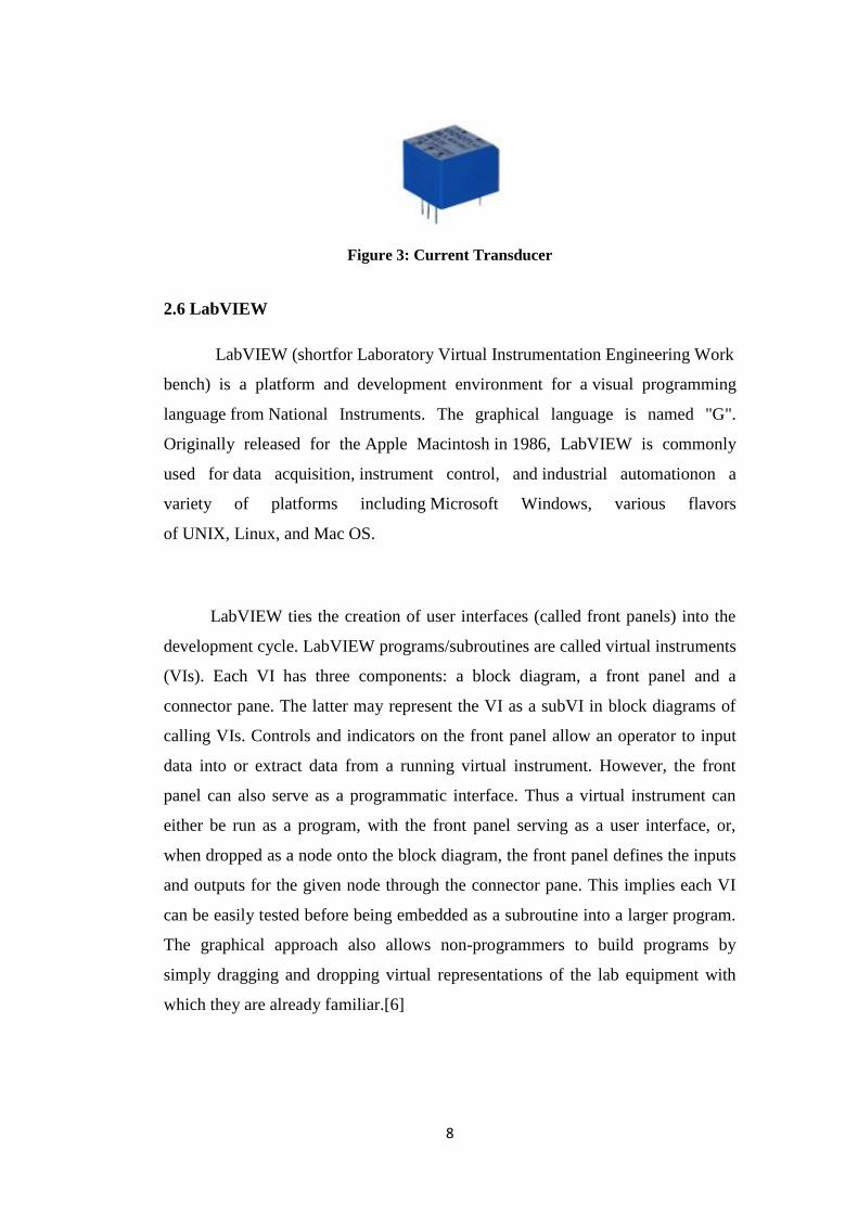
Current transducer as shown in Figure 3 can also describe a type of sensor
that measures the magnetic flux of a power conductor to sense drive motor
currents for machinery and process equipment and transmits an analog milliamp
or voltage signal to control systems. Solid corecurrent transducers have closed
loop ring transformers that must be slipped over the temporarily open end of a
power conductor. Split core current transducers have a hinged side of the
transformer ring that can be temporarily opened to allow the ring to be slipped
around a conductor that cannot be disconnected. They usually incorporate rectifier
and adjustable output conditioning circuitry to allow specific calibrations for
analog control systems.[7]
8
Figure 3: Current Transducer
2.6 LabVIEW
LabVIEW (shortfor Laboratory Virtual Instrumentation Engineering Work
bench) is a platform and development environment for a visual programming
language from National Instruments. The graphical language is named "G".
Originally released for the Apple Macintosh in 1986, LabVIEW is commonly
used for data acquisition, instrument control, and industrial automationon a
variety of platforms including Microsoft Windows, various flavors
of UNIX, Linux, and Mac OS.
LabVIEW ties the creation of user interfaces (called front panels) into the
development cycle. LabVIEW programs/subroutines are called virtual instruments
(VIs). Each VI has three components: a block diagram, a front panel and a
connector pane. The latter may represent the VI as a subVI in block diagrams of
calling VIs. Controls and indicators on the front panel allow an operator to input
data into or extract data from a running virtual instrument. However, the front
panel can also serve as a programmatic interface. Thus a virtual instrument can
either be run as a program, with the front panel serving as a user interface, or,
when dropped as a node onto the block diagram, the front panel defines the inputs
and outputs for the given node through the connector pane. This implies each VI
can be easily tested before being embedded as a subroutine into a larger program.
The graphical approach also allows non-programmers to build programs by
simply dragging and dropping virtual representations of the lab equipment with
which they are already familiar.[6]

9
The LabVIEW programming environment, with the included examples and
the documentation, makes it simpler to create small applications. This is a benefit
on one side but there is also a certain danger of underestimating the expertise
needed for good quality "G" programming. For complex algorithms or large-scale
code it is important that the programmer possess an extensive knowledge of the
special LabVIEW syntax and the topology of its memory management. The most
advanced LabVIEW development systems offer the possibility of building stand-
alone applications. Furthermore, it is possible to create distributed applications
which communicate by a client/server scheme, and thus is easier to implement due
to the inherently parallel nature of G-code. To maintain clean and legible user VI
interfaces its best to keep these tips in mind: Keep panels simple and clean, keep a
consistent style, clean up wires where ever possible, use proper terminology when
labelling controls and indicators.[6]
Figure 4 and Figure 5 show the example of front panel and block diagram
of LabVIEW. Front panel is the user interface for the program and block diagram
is the part where the programming takes place.

10
Figure 4: LabVIEW Front Panel
Figure 5: LabVIEW Block Diagram

11
CHAPTER 3
METHODOLOGY
3.1 Procedure Identification
The project is started by collecting of related data on the domestic
electrical wiring procedures and practices. Some procedures are identified for the
project to accomplished starting from gathering the required information until the
system testing and implementation. Figure 6 below shows the project
methodology.
Figure 6: Project Methodology
Literature Review
Start
End
System Design
Calibration & Data
Acquisition
System Testing
Report Writing
12
The information of domestic electrical wiring procedures and practices is
collected in the first phase. Data of domestic electrical wiring equipments such as
Earth Leakage Circuit Breakers (ELCB), Miniature Circuit Breaker (MCB) and
Fault behaviour are being discussed. The data about LabVIEW is also been
gathered and the program is studied in order to design the program to detect the
fault location.
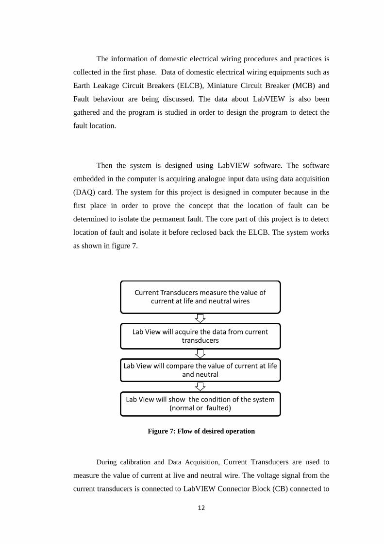
Then the system is designed using LabVIEW software. The software
embedded in the computer is acquiring analogue input data using data acquisition
(DAQ) card. The system for this project is designed in computer because in the
first place in order to prove the concept that the location of fault can be
determined to isolate the permanent fault. The core part of this project is to detect
location of fault and isolate it before reclosed back the ELCB. The system works
as shown in figure 7.
Figure 7: Flow of desired operation
During calibration and Data Acquisition, Current Transducers are used to
measure the value of current at live and neutral wire. The voltage signal from the
current transducers is connected to LabVIEW Connector Block (CB) connected to
Current Transducers measure the value of current at life and neutral wires
Lab View will acquire the data from current transducers
Lab View will compare the value of current at life and neutral
Lab View will show the condition of the system (normal or faulted)

13
Data Acquisition Card at computer. The datasheet of the current transducer used
are shown in Appendix B. Then the real time analogue input will be processed in
computer using LabVIEW program. The program is actually comparing the value
of current at live with the value of current flowing through neutral wire. The
program will show whether the system is in normal condition or experiencing
fault. All the data and results gained from the project are written in a proper
report.
3.2 Tolls and Equipments required
Software
LabVIEW 6i
Hardware
Current Transducers
Data Acquisition Card (DAQ card)
LabVIEW Connector Block

14
CHAPTER 4
RESULT AND DISCUSSION
4.1 Earth Leakage Circuit Breaker (ELCB ) and Miniature Circuit
Breaker(MCB)
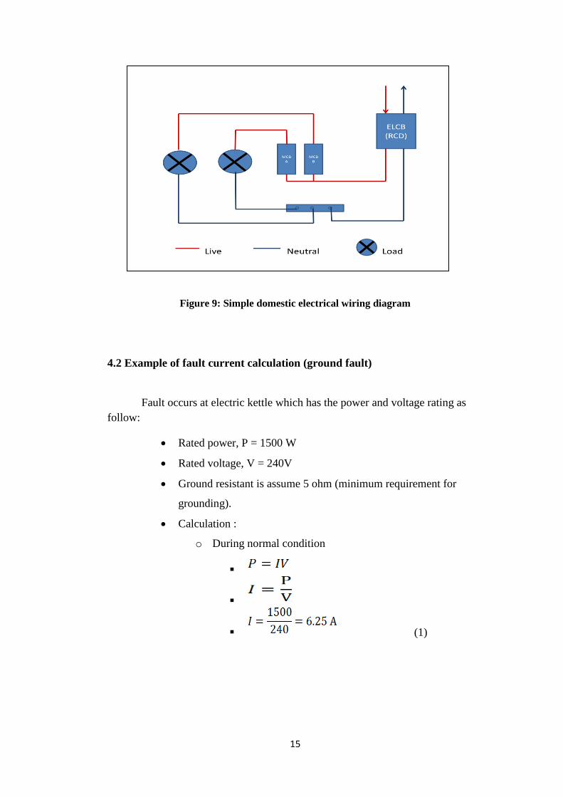
Figure 8 and 9 show the location of ELCB and MCB inside the distribution
box and the simple domestic electrical wiring diagram that most of the residential
housing has. From figure 9, the red line is the live wire where the power is
travelling to the load and the power (current) then will travel out from the load to
neutral bar before it travels back to ELCB. This is where the fault can be trace
where if the current travelling into the load is not equal to the current travelling
out of the load, it means that a leakage of current (fault) occur at the load.
Figure 8: Consumer Distribution Box
15
Figure 9: Simple domestic electrical wiring diagram
4.2 Example of fault current calculation (ground fault)
Fault occurs at electric kettle which has the power and voltage rating as
follow:
Rated power, P = 1500 W
Rated voltage, V = 240V
Ground resistant is assume 5 ohm (minimum requirement for
grounding).
Calculation :
o During normal condition
(1)
16
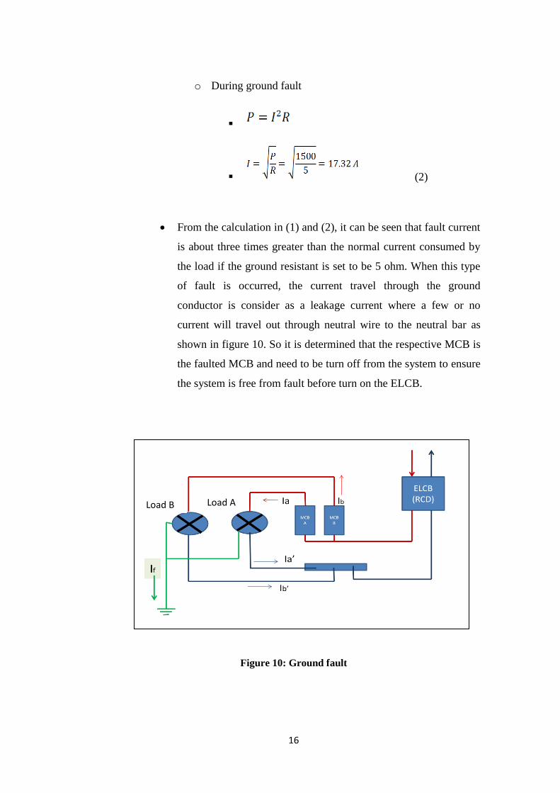
o During ground fault
(2)
From the calculation in (1) and (2), it can be seen that fault current
is about three times greater than the normal current consumed by
the load if the ground resistant is set to be 5 ohm. When this type
of fault is occurred, the current travel through the ground
conductor is consider as a leakage current where a few or no
current will travel out through neutral wire to the neutral bar as
shown in figure 10. So it is determined that the respective MCB is
the faulted MCB and need to be turn off from the system to ensure
the system is free from fault before turn on the ELCB.
Figure 10: Ground fault
Load B Load A

17
If is the fault current that travels through ground conductor to the
earth. For load A, the current at live wire is labelled as Ia and
current at its neutral wire is labelled as Ia’. It is same to load B.
When the value of current Ia’ is less that Ia, there is leakage current
at load A. So according to the system design, MCB A should be
tripped off in order to reclose the ELCB when there is no fault in
the system. The system will only trip the MCB when the different
of current reach 30 mA. The value of 30 mA is same as the
tripping condition of a standard ELCB.
The tripping condition is set to be as follows:
o If Ia’-Ia = 30 mA, trip MCB A
o If Ib’-Ib = 30mA, trip MCB B
o Then, reclose ELCB
Current transducer is giving output voltage, so assumption is made
that 30mA equals to 3V transducer output. Then at the
programming part at LabVIEW, 3V is used as the maximum
voltage difference to compare the data.

18
4.3 LabVIEW Block Diagram and Front Panel
LabVIEW is used as a program to control and determine the location of
fault. The program consists of two parts which are Block Diagram and Front
panel. Figure 11 shows the block diagram and Figure 12 shows the Front Panel of
LabVIEW that has been programmed to detect the location of fault.
Block diagram is where the programming part in LabVIEW takes place.
The interesting part is the program is written using symbols and icons and
connected by wires. Figure 11 shows the block diagram of the project.
Figure11: Program Block Diagram in LabVIEW

19
Front panel is the graphic user interface in LabVIEW as shown in Figure
12. The front panel has been design to display four graphs of current with
different colours (red, yellow, green and blue). It also will display the value of
current measured in real-time basis where the scan rate is 3scan/secs. Stop button
is also included in the front panel to make the user easier to stop the program.
There are four indicators which will light up when the system is running to show
the current condition of the system.
Figure12: Program Front Panel in LabVIEW
4.3.1 Data Acquisition
The program has been designed to acquire voltage signal from current
transducers. Figure 13 shows a connector block is used to acquire the voltage
signal from current transducers where four analogue input ports have been
selected. The Connector Block is then connected to LabVIEW Data Acquisition
Card that attach to computer’s motherboard. The LabVIEW program that has been
created for acquiring the data from Data Acquisition Card is also shown in Figure
14 and 15.

20
Figure13: Connector Block
Figure 14: A part of program that acquire voltage input from Data Acquisition
Card
Figure 15: Four inputs that feed to the program

21
4.3.2 Data Comparison and Fault Detection
The value of current at live wire and neutral wire in voltage form is
compared respectively in the program. The value of current at live wire from loop
1 is compared to the value of current at neutral wire from loop 1. The same
operation is performed to loop 2. The value difference is set to be 3V for the
system to detect fault. Figure 16 and 17 show the program for comparing the
voltage values from current transducers.
Figure 16: Program to compare values of current at live and neutral wire in loop 1
Figure 17: Program to compare values of current at live and neutral wire in loop 2

22
The graph of current values (in voltage form) is shown in front panel. The
scan rate for this program is set to be 3 seconds per scan. For two loops system,
the program requires four input channels and four different graphs are shown with
different colours. There are two indicators in each loop showing the current
condition of the system whether in normal condition or detecting fault. The front
panel also shows the values of current at live and neutral wire which are recorded
from current transducers. Figures 18 to 21 show the front panel in various
condition of the system.
Figure 18 shows the system is in normal condition where no fault is
detected. The front panel will show the value of current at both live and neutral
wire. The value of live current will be compared to the value of current at neutral
wire and the normal condition indicator will light up when the different is less that
preset value (3V). The red graph represents the live current at loop 1, yellow
represents the neutral current at loop 1, the green represents live current at loop 2
and the blue graph represents the neutral current at loop 2. The graphs show the
value of current respect to time (secs).
Figure 18: System in normal condition

23
Figure 19 shows that fault has been detected at loop 1 and loop 2 remains
in normal condition. The value different between live and neutral current at loop 1
is more that 3V, so the system will detect loop 1 as the location of fault.
Figure 19: Fault detected at Loop 1
Figure 20 shows a fault is detected at loop 2. The result is about the same
with result shown in Figure 18 but the location of fault detected is different. The
figure shows that when LabVIEW detects the difference is 3.37V which is more
than 3V at live and neutral wire at loop 2, so it will declare that the loop 2 is
experiencing fault. So the location of fault can be determined.

24
Figure 20: Fault detected at Loop 2
Figure 21 shows that fault is detected at booth location (loop1 and loop 2).
The value difference at live and neutral wire for both loops are more than 3V, so
the system detects the fault at both loops.
Figure 21: Fault detected at both Loop
25
CHAPTER 5
CONCLUSION AND RECOMMENDATION
5.1 Conclusion
The LabVIEW program that has been designed is able to detect the
location of fault in a domestic electrical system. The purpose of determining the
location of fault is to isolate the permanent fault in a system before the other
system turn on back the Earth Leakage Circuit Breaker (ELCB). This is to ensure
the reliability of power supply to protect the critical equipments in domestic
building. LabVIEW is seen to be a good medium to develop the program because
it can acquire real time analogue input data as well as performing the logical part
to detect the fault. So when the location of fault is determined, an automated
system to isolate the faulted Miniature Circuit Breaker (MCB) can be designed to
cater for both temporary and permanent faults. The designed system will give a lot
of advantages for consumers to protect their equipments and properties when they
are not around. So the objective to design a system that can determine the location
of fault in domestic electrical wiring system is achieved.

26
5.2 Recommendation
Current transducers are used to measure the value of current at live and
neutral wires. But there are many types of current transducers available in the
market. It is recommended to use the clamping type current transducer rather than
using the Printed Circuit Board (PCB) type. The clamping type gives a better
efficiency but the cost is much higher than the PCB type. For future works, it is
recommended to use a latest version of LabVIEW software and the Data
Acquisition (DAQ) Card. The latest version used will be easier in term of
designing and finding the resources to refer.

27
REFERENCES
[1] Trevor Linsley, “ Advanced Electrical Installation Work”, Newnews
Fifth Edition, 2008.
[2] Residential Wiring, second edition, Gary J. Rockis, Suzanne M. Rockis
and Thomas E. Proctor.
[3] Guide to The Selection & Use of Residual Current devices, RT214:2005
Edition 1.
[4] http//:www.electronics-manufacturers.com
[5] http://en.wikipedia.org/wiki/Residual-current_device
[6] http://www.bookrags.com//wiki/LabVIEW
[7] http://www.wisegeek.com/what-are-current-transducers.htm
[8] http://www.ni.com/labview/whatis/
[9] http://www.ee.buffalo.edu/faculty/paololiu/edtech/roaldi/tutorials/
labview.htm
[10] Moriarty PJ, Gallagher BL, Mellor CJ, Baines RR, P. J.; Gallagher, B.
L.; Mellor, C. J.; Baines, R. R. (October 2003). "Graphical computing in
the undergraduate laboratory: Teaching and interfacing with
LabVIEW". American Journal of Physics (AAPT) 71 (10): 1062–1074.
doi:10.1119/1.1582189.
[11] http://www.thecircuitdetective.com/index.htm
[12] http://zone.ni.com/devzone/cda/tut/p/id/4290
[13] http://www.ni.com/pdf/manuals/370719c.pdf

28
APPENDICES
29
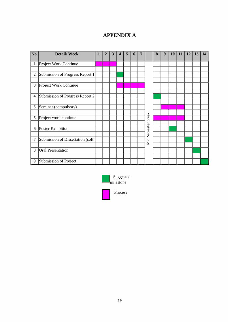
APPENDIX A
No. Detail/ Week 1 2 3 4 5 6 7 8 9 10 11 12 13 14
1 Project Work Continue
2 Submission of Progress Report 1
3 Project Work Continue
4 Submission of Progress Report 2
5 Seminar (compulsory)
5 Project work continue
6 Poster Exhibition
7 Submission of Dissertation (soft
bound)
8 Oral Presentation
9 Submission of Project
Dissertation (Hard Bound)
Suggested
milestone
Process
Mid
Sem
este
r b
reak

30
APPENDIX B