automation logic control & bay protection device key benefits
TRANSCRIPT

471
Spec
ializ
ed P
rote
ctio
n &
Cont
rol
g MultilinDigital Energy
• Backupprotectionfunctionsalongwithpowerfulprogrammableautomationcontrollerwithmathengineeliminatestheneedforseparatesubstationprogrammablelogiccontroller
• Highlyreliableanddependablecontrollerwithitsdeterministicreal-timeoperatingsystemensuringtheexecutionofautomationlogicregardlessofthenumberofequationsconfigured
• LocalHMIprovidingrealtimebaycontrolwithconfigurablesinglelinediagramswithcontrolofuptosixbreakers
• High-endloadsheddingblockswithmultiplestagesofunderfrequency,rate-of-change-of-frequencyandundervoltageelements
• Customizableannunciatorpanelcapableofhandlingupto288alarmsusingapalletof16colorseliminatestheneedforaseparatepanel
• High-endfaultanddisturbancerecording,includinginternalrelayoperatingsignalseliminatestheneedfordigitalfaultrecordersanddisturbancerecorders
• Easytouseandsetupsoftwarereducinginstallation,maintenance,andoperationcosts
• PhasorMeasurementUnit-SynchronizedphasorinformationaccordingtoIEEEC37.118standardfordetectionofsysteminstability
• Intuitivelargefrontpanelcolorscreenwithpre-configuredandcustomizabledisplayofmetering,faultrecords,eventrecordsandequipmentstatus
• Customprotectionandbayinterlockingschemes• Baycontrollerforcommonbus-bararrangements• Substationalarmconcentrator,annunciator,andcontroller• Controlforupto6breakersand30disconnectswitches
• Custombustransferschemes• Standalonebreakerfail&reclosing• Controllerforcustomapplicationsinutilityandindustrial
plants
Monitoring and Metering
Ease of Use and Security • Graphicalprotectionandautomationlogicprogramming• RealtimeLogicMonitoringtosimplifycommissioningand
troubleshooting• Documentandsoftwarearchivingtoolsettoensurereference
materialanddeviceutilitiesareup-to-date• EnerVista™Integratorprovidingeasyintegrationofdata
(SCADAorDCS)intoneworexistingsystems
Bay Protection & Control• Dedicatedautomationcontrollerwith4000linesoflogicata
deterministic50msecexecutionrate• Powerfulmath,controlandbooleanoperators• 10stagesunder/overfrequencyprotectionforloadshedding• 4stagesofrate-of-change-offrequencyforloadshedding• 6stagesofunder-voltageelementsforloadshedding• Dedicatedprotectionlogicat1msecexecutionrate• DedicatedHMIforbreakeranddisconnectcontrol• Synchrocheckandlinecheckfunctionformulti-breaker• Single/threepoleautorelcosing• Dualbreakerfailureprotection• Directandtele-protecionelementsareavailableusingthe
Inter-relaycommunicationcard
• CTandVTmonitoring• Metering-current,voltage,frequency,power,energyand
phasorsasperIEEEC37.118• Faultrecorder-256samples/cycle,30secofstorage
capacity• Disturbancerecorder–1sample/cycle,5minofstorage
capacity• Eventrecorder-8000timetaggedevents,with0.5msscan
ofdigitalinputs• Comprehensivedisplayofmetering,phasors,maintenance
andfaultinformationinthefrontpanel.
Communications• IEC61850,DNP3,ModbusRTU,ModbusTCP/IP,IEC60870-5-104• ThreeindependentlyconfigurableIP’swithfail-overfeatures• Inter-relaycommunicationcardtoenableimplementationof
pilot-schemesbasedonstandardcommunicationprotocols• FrontUSBformaintenance&downloadingrecordsandevents
C90Plus
FEATURES
APPLICATIONS
KEY BENEFITS
AUTOMATION LOGIC CONTROL & BAY PROTECTION DEVICE

Digital Alarm Annunciator• 288customizablealarmsin
multiplepagesusingapalletof16colors
• Eliminatestheneedforseparateannunciator
• Descriptiveself-testmessages
Intuitive HMI• Userconfigurablesinglelinediagrams
usingIEC/ANSIlibrarysymbols• Localcontrolandstatusindicationof
breakers&disconnectswitches,20userprogrammablepushbuttons
• Local/Remotecontrol• Fault,event,disturbanceandtransient
reports
Bay Protection• Overcurrent,over/undervoltage,
over/underfrequency• Breakerfailure,autoreclose,synch
check• 512linesofProtectionFlexLogic™
@1msecexecution
Advanced Automation Controller• Built-inindustryhardenedlogiccontroller• 4096linesofindependentuser
programmablelogic,50msecexecutionrate
• AdvancedMath,BooleanandControloperations
Advanced Communication Capabilities• UptothreeindependentEthernetports
withredundantfast-over• IEC61850,DNP3,MODBUSTCP/IP,
IEC60870-5-104protocols•FrontUSBportforhighspeeddatatransfer
Advanced Recorders• Eliminatestheneedforstand-alone
disturbancerecorders• Configurableandupto256samples/cycle,
1mindurationrecorder• Dedicateddisturbancerecorderfor
recordinglongtermevents• SynchrophasorsoverEthernet
C90Plus Controller
Advanced disturbance recorder eliminates stand-alone DFR and Phasor Measurement Unit
Digital fault recorder summary with the latest information on the events, faults, transients and disturbances.
Real time display of the fundamental phasors of voltage and current in the front panel HMI.
Real time phasor information of fundamental and sequence components
472
Spec
ializ
ed P
rote
ctio
n &
Cont
rol
C90PlusController
www.GEDigitalEnergy.com
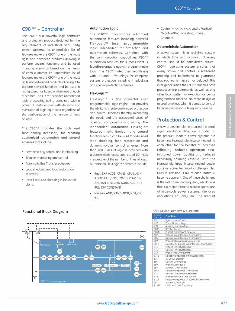
Functional Block Diagram
DEVICENUMBER
21G21P2527P27X50BF50DD50G50N50P50_251G51N
Ground DistancePhase DistanceSynchrocheckPhase UndervoltageAuxiliary UndervoltageBreaker FailureCurrent Disturbance DetectorGround Instantaneous OvercurrentNeutral Instantaneous OvercurrentPhase Instantaneous OvercurrentNegative Sequence Instantaneous OvercurrentGround Time OvercurrentNeutral Time Overcurrent
FUNCTION
ANSI DEVICE NUMBERS AND FUNCTIONSDEVICENUMBER
51P51_25259N59P59X59_267N67P67_2687879
Phase Time OvercurrentNegative Sequence Time OvercurrentAC Circuit BreakerNeutral OvervoltagePhase OvervoltageAuxiliary OvervoltageNegative Sequence OvervoltageNeutral Directional OvercurrentPhase Directional OvercurrentNegative Sequence Directional OvercurrentPower Swing BlockingOut-of-Step TrippingAutomatic Recloser
FUNCTION
837709AE.CDR
50N (2) 51N (2) 67N/G (2)
59P
59N
52 52
79
50P (2) 50_2 (2) 51P (2) 51_2 (2) 50BF (2) 67P (2) 67_2 (2)
59X 27X
50G (2) 51G (2)
50DD
Monitoring
C90Plus Controller System
CLOSE TRIP
25 (2)
FlexElementT M Transducer
InputsMetering
27P (2)
C90Plus – ControllerThe C90Plus is a powerful logic controllerand protection product designed for therequirements of industrial and utilitypower systems. Its unparalleled list offeaturesmaketheC90Plusoneofthemostagile and advanced products allowing itperform several functions and be usedin many scenarios based on the needsof each customer. Its unparalleled list offeaturesmaketheC90Plusoneofthemostagileandadvancedproductsallowingittoperform several functionsandbeused inmanyscenariosbasedontheneedofeachcustomer.TheC90Plusprovidesunmatchedlogic processing ability combined with apowerful math engine with deterministicexecutionof logicequationsregardlessofthe configuration of the number of linesoflogic.
The C90Plus provides the tools andfunctionality necessary for creatingcustomized automation and controlschemesthatinclude:
• Advancedbaycontrolandinterlocking
• Breakermonitoringandcontrol
• AutomaticBusTransferschemes
• Loadsheddingandloadrestorationschemes
• UltraFastLoadsheddinginindustrialplants
Automation Logic
The C90Plus incorporates advancedautomation features including powerfulF lexLogic™ (user programmablelogic) independent for protection andautomation schemes. Combined withthe communication capabilities, C90Plus
automation features far surpass what isfoundinaveragerelayswithprogrammablelogic. The C90Plus integrates seamlesslywith UR and URPlus relays for completesystem protection including interlockingandspecialprotectionschemes.
FlexLogic™
FlexLogic™ is the powerful userprogrammable logic engine that providestheabilitytocreatecustomizedprotectionand control schemes thereby minimizingthe need, and the associated costs, ofauxiliary components and wiring. Theindependent automation FlexLogic™features math, Boolean and controlfunctionswhichcanbeusedforadvancedload shedding, load restoration anddynamic volt/var control schemes. Morethan 4000 lines of logic is provided withadeterministicexecutionrateof50msecirrespectiveofthenumberoflinesoflogic.AutomationFlexLogic™operatorsinclude:
• Math:EXP,ACOS,ATAN2,ATAN,ASIN,FLOOR,CEIL,LOG,LOG10,POW,SIN,COS,TAN,NEG,ABS,SQRT,ADD,SUB,MUL,DIV,CONSTANT
• Boolean:AND,NAND,NOR,NOT,OR,XOR
• Control:=,<=,!=,>=,>,Latch,Positive/Negative/Dualoneshot,Timers,Counters
Deterministic Automation
A power system is a real-time systemin which time and accuracy of everycontrol should be considered critical.C90Plus operating system ensures thatevery action and control is scheduledproperly and beforehand to guaranteethat nothing is missed nor delayed. ThisintelligenceinsidetheC90Plushandlesbothprotection trip commands aswell as anyotherlogicwrittenforexecutionasperitsprogrammed timeline.Nomoredelays ormissedtimelineswhenitcomestocontrolbecauseprocessoris‘busy’orotherwise.
Protection & ControlAnewprotectionelementcalledthesmallsignal oscillation detection is added tothe product. Modern power systems arebecoming increasingly interconnected toeach other for the benefits of increasedreliability, reduced operation cost ,improved power quality and reducednecessary spinning reserve. With theincreasingly large interconnected powersystems some technical challenges alsoURPlus revision 1.80 release notes 6becomeapparent.Oneofthesechallengesistheinter-arealowfrequencyoscillationsthatisamajorthreattoreliableoperationsof large-scale power systems. Inter-areaoscillations not only limit the amount
DeviceNumber Function25 SynchronismCheck27P PhaseUndervoltage27X AuxiliaryUndervoltage50BF BreakerFailure50DD CurrentDisturbanceDetector50G GroundInstantaneousOvercurrent50N NeutralInstantaneousOvercurrent50P PhaseInstantaneousOvercurrent50_2 NegativeSequenceInstantaneousOvercurrent51G GroundTimeOvercurrent51N NeutralTimeOvercurrent51P PhaseTimeOvercurrent51_2 NegativeSequenceTimeOvercurrent52 ACCircuitBreaker59N NeutralOvervoltage59P PhaseOvervoltage59X AuxiliaryOvervoltage59_2 NegativeSequenceOvervoltage67N NeutralDirectionalOvercurrent67P PhaseDirectionalOvercurrent67_2 NegativeSequenceDirectionalOvercurrent79 AutomaticRecloser81U/O Underandoverfrequency
ANSIDeviceNumbers&Functions
473
Spec
ializ
ed P
rote
ctio
n &
Cont
rol
C90PlusController
www.GEDigitalEnergy.com
of power transfer, but also threatenthe system security and equilibrium,as they may lead to system instabilityand cascading outages. Therefore, it isessential to identify the characteristicsof the inter-area oscillations, includingoscillationfrequencyanddampingratio,sothatproperactionscanbetakenbasedontheresults.Thisisrequiredtoimprovethesystemdampingandmaintainstability inthepowersystem.TheC90Pluscandetectthese inter-area oscillations and provideanalarmorevenatripsignaltopreventalarge-scalesystemdisturbance.
Overcurrent function
The C90Plus provides multiple stages ofovercurrent functions for phase, neutralandground.Overcurrentfunctionsinclude:
• Instantaneousandtimedovercurrentelementsforphase,neutral,groundandnegativesequenceprotection
• Directionalsupervisionisavailableforphaseneutralandnegativesequenceelements
• TimeO/CelementscanindividuallybesettouseIEEE,IECorcustomFlexCurvesTM
Over and under voltage protection
Long linesunder lightly loadedconditionsor no-load or sudden loss of powermayexperience voltages exceeding the ratedper unit voltage level of the line. Usethe phase overvoltage element of theC90Plus to initiate a local trip aswell as aremote trip using direct transfer trip. TheC90Plus also provides additional voltagefunctions including neutral overvoltage,negativesequenceovervoltageandphaseundervoltage. The phase undervoltagecan be programmed as definite time orinversetime.
Over and under frequency Protection
The multiple stages of under and overfrequencyelementscanbeusedtoinitiateloadsheddingorremedialactionsschemesor frequency-based load restorationschemes during lack of generation in thenetwork or due to sudden load drops.Combinedwith theadvancedautomation
capabilities of the C90Plus flexible, specialprotection schemes, advanced loadshedding and load restoration schemescanbebuilt .The C90Plus supports the most popularindustrystandardprotocolsenablingeasy,direct integration into DCS and SCADAsystemsincluding:
• IEC61850
• DNP3
• EthernetGlobalData(EGD)
• IEC60870-5-104
• ModbusRTU,ModbusTCP/IP
Interoperability with Embedded IEC 61850
Use the C90Plus with integrated IEC61850 to lower costs associated withprotection, control and automation. GEMultilin’s leadership in IEC 61850 comesfrom thousands of installed devices andfollows on many years of developmentandoperationalexperiencewithUCA2.0.
• ReplaceexpensivecopperwiringbetweendeviceswithdirecttransferofdatausingGOOSEmessaging
• ConfiguresystemsbasedonIEC61850andalsomonitorandtroubleshoottheminreal-timewithEnerVista™ViewpointEngineer
• IntegrateGEMultilinIEDsandgenericIEC61850-compliantdevicesseamlesslyinEnerVista™ViewpointMonitoring
Extreme Communication
• Highreliablecommunicationcardwithautomaticfailoverandextremelyfastredundantschemes
• Inter-relaycommunicationcardtoenableimplementationofpilot-schemesthatarebasedonstandardcommunicationprotocols,andboth“Direct”and“Tele-Protection”inputsandoutputelementsareavailable
Ease of Use and SecurityEase-of-use and quick setups areconsidered throughout every applicationand configuration parameter requiringvirtually no training for those working inthe power industry. The EnerVista™ Suiteis an industry-leading set of softwareprograms that simplifies every aspect ofusing the C90Plus relay. The EnerVistaTMsuiteprovidesall the tools tomonitor thestatus of the protected asset, maintainthe relay, and integrate informationmeasured by the C90Plus into DCS or
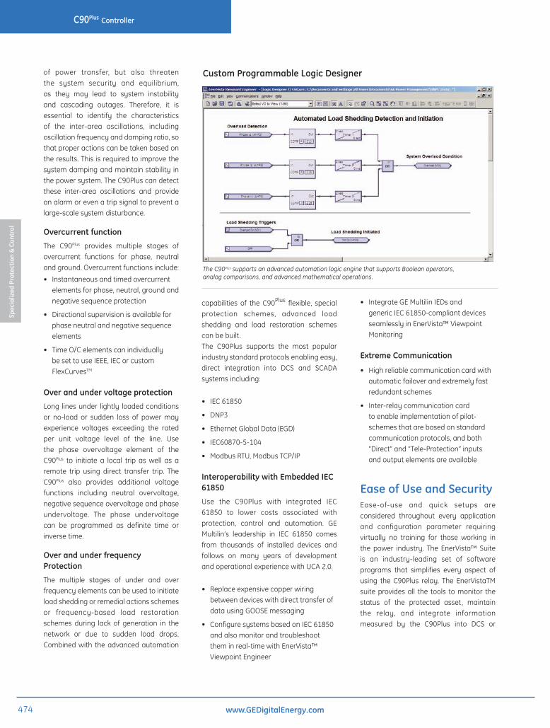
Custom Programmable Logic Designer
The C90Plus supports an advanced automation logic engine that supports Boolean operators, analog comparisons, and advanced mathematical operations.
474
Spec
ializ
ed P
rote
ctio
n &
Cont
rol
C90PlusController
www.GEDigitalEnergy.com

SCADA monitoring systems. ConvenientCOMTRADEandSequenceofEventsviewersare an integral part of the URPlus Setupsoftware includedwitheveryURPlus relay,tocarryoutpostmortemeventanalysis toensureproperprotectionsystemoperation.
Security and NERC/CIP
• AuditTrail
• Passwordprotectionandauthentication
• Supportforalphanumericpasswords
• Role-basedaccesscontroltomanagemultiplepersonnelrightsasperANSIINCITS359-2004
EnerVista™ Launchpad
EnerVista™ Launchpad is a powerfulsoftware package that provides userswith all of the setup and support toolsneededforconfiguringandmaintainingGEMultilinproducts.ThesetupsoftwarewithinLaunchpadallowsconfiguringofdevicesinreal-time by communicating using serial,Ethernet,ormodemconnections,orofflinebycreatingsettingfilestobesenttodevicesat a later time. Included in Launchpad isa document archiving and managementsystemthatensurescriticaldocumentation
is up-to-date and available when needed.Documentsmadeavailableinclude:
• Manuals
• ApplicationNotes
• GuideformSpecifications
• Brochures
• WiringDiagrams
• FAQ’s
• ServiceBulletins
Viewpoint Engineer
ViewpointEngineerisasetofpowerfultoolsthat will allow you to configure and testyourrelaysatasystemlevelinaneasy-to-use,graphicaldrag-and-dropenvironment.Viewpoint Engineer provides the followingconfigurationandcommissioningutilities:
• GraphicalLogicDesigner
• GraphicalSystemDesigner
• GraphicalLogicMonitor
• GraphicalSystemMonitor
User Interface and HMIThe C90Plus provides extensive local HMIcapability through two dedicated displaypanels.Oneservesasadigitalannunciatorand the other optional HMI is for displayandcontrolfunctions.
Annunciator
Enhanced HMI and Annouciator panelson the front of the C90Plus make it oneof the most powerful human machineinterfaces on local units. The C90Plusprovidesanembedded,configurablecolorLCDannunciatoronthefrontpanelofthedeviceeliminatingtheneedforLEDlabelsand separate annunciators in the relaypanel.
• Anycontact/direct/remoteinputorinternallygeneratedFlexlogicTMoperandcanbeassignedtobedisplayedontheannunciator.
• Upto288targetsmaybeassigned.Thedisplaycanbeconfiguredfor12/24/48alarmsperpagetoamax.of24pagesusinga16-colorforbettervisualizationandcustomization
Power System TroubleshootingThe C90Plus contains tools that allow for early detection of impending breaker problems and allow for maintenance to be performed before serious damage occurs.
Breaker Latch Release Time:
Indicates how long it took for the breaker latch to
release from the time the Trip Coil was energized by
the relay
Arc Extinguish Time:
Indicates the length of time that was required for the
breaker to extinguish the arc and finally clear the fault
Breaker Mechanism Travel Time:
Indicates time interval required for the breaker
mechanism to travel to its rest position
Triggering a waveform on each breaker operation can identify changes in the length of time each part or mechanism in the breaker takes to perform its function.
475
Spec
ializ
ed P
rote
ctio
n &
Cont
rol
C90PlusController
www.GEDigitalEnergy.com

Bay Configurations
The C90Plus has 12 pre-configured baysingle-line diagrams and correspondingcontrols for each of the bay equipment.Users can also program their own singleline diagrams using the ANSI/IEC librarysymbols provided in the EnerVista set-upprogram.
Two-Main and Transfer Bus configuration
Double Bus configuration
Breaker-and-half configuration
• Multipleprogrammablecontrolpushbuttons,tenpushbuttonsperpagewithmultiplelevelsofcontrol.
• Local/RemoteControl
Sequence of event records with the ability to view time difference between two events for troubleshooting and analysis.
• Pre-programmedcomprehensivedisplaysfor:
•Metering
•BayControl
•FaultReports
•SequenceofEventReports
•FaultRecords
•DeviceDiagnostics
•EquipmentManager
•RealTimePhasorDisplaysofVoltage,CurrentandSequencecomponents
Phasor display of sequence components showing the standing unbalance in the line.
Front Panel USB
The front panel of the C90Plus provides aUSB 2.0 host for field laptop connectionsfor high-speed data transfer andmakingdownloadinganduploadingfasterthanaconventionalRS232connection.
• Aseparateself-testmessagepageontheannunciatorpanelshowsclearerrormessagesaboutthedevicehealth,greatlyassistinginidentifying,andcorrectingdevicerelatedissues.
• ForeasymaintenanceandassesstmanagementproductinformationsuchasIPaddressesandserialnumbersofeachmodulearealsoaccesiblewithouttheneedtoconnecttotheunit
12 to 48 user configurable alarms per page eliminates the need for a separate annunciator.
HMI
• Comprehensivedatavisualization.
Easy to read large display of metering values.
• UserprogrammablesinglelinediagramsupportedbyANSI/IECsymbols.Pre-programmedsinglelinediagramsforbaymonitoringandcontrolforcommonbusconfigurations,includingring-bus,doublebreakerandbreaker-and-halfconfigurations.
Single Bus Configuration
476
Spec
ializ
ed P
rote
ctio
n &
Cont
rol
C90PlusController
www.GEDigitalEnergy.com
mm
mm
mm
mm
mm
mm
mm
mm
mmmm
mm
mm
mm
mm
mm
mm
mm
mm
mm
mmmm
mm
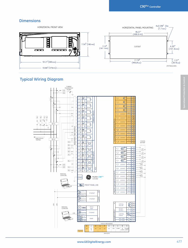
Dimensions
g Multilin C90PlusController
Typical Wiring Diagram
477
Spec
ializ
ed P
rote
ctio
n &
Cont
rol
C90PlusController
www.GEDigitalEnergy.com

Technical SpecificationsAUTORECLOSUREApplications: twobreakersTripping schemes: single-poleandthree-poleReclose attempts: upto4beforelockoutReclosing mode: selectableBreaker sequence: selectableAUXILIARY OVERVOLTAGEPickup level: 0.000to1.100puinstepsof0.001Dropout level: <98%ofpickupLevel accuracy: ±0.5%ofreadingfrom10to208VPickup delay: 0.00to600.00secondsinsteps
of0.01Reset delay: 0.00to600.00secondsinsteps
of0.01Timing accuracy: ±3%ofoperatetimeor±4ms
(whicheverisgreater)Operate time: <2cyclesat1.10×pickupat60HzAUXILIARY UNDERVOLTAGEPickup level: 0.000to1.100puinstepsof0.001Dropout level: >102%ofpickupLevel accuracy: ±0.5%ofreadingfrom10to208VCurve shapes: GEIAVinverse,definitetimeCurve multiplier: 0.00to600.00instepsof0.01Timing accuracy: ±3%ofoperatetimeor±4ms
(whicheverisgreater)BREAKER FAILUREMode: single-pole,three-poleCurrent supervision: phasecurrent,neutralcurrentSupervision pickup: 0.001to30.000puinstepsof0.001Supervision dropout: <98%ofpickupSupervision accuracy at 0.1 to 2.0 × CT:
±2%ofrated
Supervision accuracy at >2.0 × CT:
±2.5%ofreading
Time accuracy: ±3%or4ms(whicheverisgreater)BREAKER FLASHOVEROperating quantity: phasecurrent,voltage,andvoltage
differencePickup level voltage: 0.000to1.500puinstepsof0.001Dropout level voltage:
97to98%ofpickup
Pickup level current: 0.000to1.500puinstepsof0.001Dropout level current:
97to98%ofpickup
Level accuracy: ±0.5%or±0.1%ofrated(whicheverisgreater)
Pickup delay: 0.000to65.535secondsinstepsof0.001
Time accuracy: ±3%or±42ms(whicheverisgreater)
Operate time: <42msat1.10×pickupat60HzCONTACT INPUTSInput rating: 300VDCmaximumOn threshold: 70%ofnominalvoltagesettingor
20V(whicheverisgreater)Off threshold: 30%ofnominalvoltagesettingor
15V(whicheverisgreater)Bounce threshold: 50%ofnominalvoltagesettingor
20V(whicheverisgreater)AZ threshold: 80%ofnominalvoltagesettingOvervoltage threshold:
130%ofnominalvoltagesettingor285Vmaximum
Maximum current: 10mAduringturnon,0.5mAsteady-state
Nominal voltage: 24to250VInput impedance: activeRecognition time: <1msDebounce timer: 1.50to16.00msinstepsof0.25Chatter detection timer:
1to100seconds
Chatter state changes:
10to100
DISTURBANCE DETECTOR (50DD)Type: sensitivecurrentdisturbance
detectorRange: 0.004to0.04pu(twicethecurrent
cut-offlevelthreshold)FLEXCURVES™Number: 4(AthroughD)Reset points: 40(0through1ofpickup)Operate points: 80(1through20ofpickup)Time delay: 0to65535msinstepsof1FLEXELEMENTS™Elements: 8Operating signal: anyanalogactualvalue,ortwo
valuesindifferentialmodeOperating signal mode:
signedorabsolutevalue
Operating mode: level,deltaComparator detection:
over,under
Pickup level: –90.000to90.000puinstepsof0.001
Hysteresis: 0.1to50.0%instepsof0.1Delta dt: 20msto60daysPickup delay: 0.000to65.535secondsinsteps
of0.001Dropout delay: 0.000to65.535secondsinsteps
of0.001
FLEXMATRIXPrinciple: aggregatesandconditionssignals
fortrippingandauxiliaryfunctionsTiming accuracy: ±1msFLEX STATESNumber: upto256logicalvariablesgrouped
under16ModbusaddressesProgrammability: anylogicalvariable,contact,or
virtualinputGROUND INSTANTANEOUS OVERCURRENTPickup level: 0.000to30.000puinstepsof0.001Dropout level: <98%ofpickupLevel accuracy at 0.1 to 2.0 × CT:
±0.5%ofreadingor±1%ofrated(whicheverisgreater)
Level accuracy at >2.0 × CT:
±1.5%ofreading
Overreach: <2%Pickup delay: 0.00to600.00secondsinsteps
of0.01Reset delay: 0.00to600.00secondsinsteps
of0.01Operate time: <16msat3×pickupat60HzTiming accuracy for operation at 1.5 × pickup:
±3%or±4ms(whicheverisgreater)
GROUND TIME OVERCURRENTCurrent: phasororRMSPickup level: 0.000to30.000puinstepsof0.001Dropout level: <98%ofpickupLevel accuracy at 0.1 to 2.0 × CT:
±0.5%ofreadingor±1%ofrated(whicheverisgreater)
Level accuracy at >2.0 × CT:
±1.5%ofreading
Curve shapes: IEEEModeratelyInverse,IEEEVeryInverse,IEEEExtremelyInverse,IEC(BS)A,IEC(BS)B,IEC(BS)C,IECShortInverse,IACInverse,IACShortInverse,IACVeryInverse,IACExtremelyInverse,I2t,FlexCurves™(programmable),definitetime(0.01secondbasecurve)
Curve multiplier: 0.01to600.00instepsof0.01Reset type: instantaneous/timed(perIEEE)
Timingaccuracyfor1.03to20×pickup:±3.5%ofoperatingtimeor±1cycle(whicheverisgreater)
NEGATIVE-SEQUENCE DIRECTIONAL OVERCURRENTDirectionality: co-existingforwardandreversePolarizing: voltagePolarizing voltage: V_2Operating current: I_2Level sensing (zero-sequence):
|I_0|–K×|I_1|
Level sensing (negative-sequence):
|I_2|–K×|I_1|
Restraint, K: 0.000to0.500instepsof0.001Characteristic angle: 0to90°instepsof1Limit angle: 40to90°instepsof1,independent
forforwardandreverseAngle accuracy: ±2°Offset impedance: 0.00to250.00ohmsinstepsof
0.01Pickup level: 0.05to30.00puinstepsof0.01Dropout level: <98%Operation time: <16msat3×pickupat60HzNEGATIVE-SEQUENCE INSTANTANEOUS OVERCURRENTPickup level: 0.000to30.000puinstepsof0.001Dropout level: <98%ofpickupLevel accuracy at 0.1 to 2.0 × CT:
±0.5%ofreadingor±1%ofrated(whicheverisgreater)
Level accuracy at >2.0 × CT:
±1.5%ofreading
Overreach: <2%Pickup delay: 0.00to600.00secondsinsteps
of0.01Reset delay: 0.00to600.00secondsinsteps
of0.01Operate time: <20msat3×pickupat60Hz
Timingaccuracyforoperationat1.5×
pickup: ±3%or±4ms(whicheverisgreater)
NEGATIVE-SEQUENCE OVERVOLTAGEPickup level: 0.000to1.250puinstepsof0.001Dropout level: <98%ofpickupLevel accuracy: ±0.5%ofreadingfrom10to208VPickup delay: 0.00to600.00secondsinsteps
of0.01Reset delay: 0.00to600.00secondsinsteps
of0.01Timing accuracy: ±3%or±20ms(whicheveris
greater)Operate time: <30msat1.10×pickupat60Hz
NEGATIVE-SEQUENCE TIME OVERCURRENTPickup level: 0.000to30.000puinstepsof0.001Dropout level: <98%ofpickupLevel accuracy at 0.1 to 2.0 × CT:
±0.5%ofreadingor±1%ofrated(whicheverisgreater)
Level accuracy at >2.0 × CT:
±1.5%ofreading
Curve shapes: IEEEModeratelyInverse,IEEEVeryInverse,IEEEExtremelyInverse,IEC(BS)A,IEC(BS)B,IEC(BS)C,IECShortInverse,IACInverse,IACShortInverse,IACVeryInverse,IACExtremelyInverse,I2t,FlexCurves™(programmable),definitetime(0.01secondbasecurve)
Curve multiplier: 0.01to600.00instepsof0.01Reset type: instantaneous/timed(perIEEE)
andlinearTimingaccuracyfor1.03to20×pickup:±3.5%ofoperatingtimeor±1cycle(whicheverisgreater)
NEUTRAL DIRECTIONAL OVERCURRENTDirectionality: co-existingforwardandreversePolarizing: voltage,current,dualPolarizing voltage: V_0orVXPolarizing current: IGOperating current: I_0Level sensing: 3×(|I_0|–K×|I_1|),IG;independent
forforwardandreverseRestraint (K): 0.000to0.500instepsof0.001Characteristic angle: –90to90°instepsof1Limit angle: 40to90°instepsof1,independent
forforwardandreverseAngle accuracy: ±2°Offset impedance: 0.00to250.00ohmsinstepsof
0.01Pickup level: 0.002to30.000puinstepsof0.01Dropout level: <98%Operation time: <16msat3×pickupat60HzNEUTRAL INSTANTANEOUS OVERCURRENTPickup level: 0.000to30.000puinstepsof0.001Dropout level: <98%ofpickupLevel accuracy at 0.1 to 2.0 × CT:
±0.5%ofreadingor±1%ofrated(whicheverisgreater)
Level accuracy at >2.0 × CT:
±1.5%ofreading
Overreach: <2%Pickup delay: 0.00to600.00secondsinsteps
of0.01Reset delay: 0.00to600.00secondsinsteps
of0.01Operate time: <20msat3×pickupat60HzTiming accuracy for operation at 1.5 ×pickup: ±3%or±4ms(whicheveris
greater)NEUTRAL OVERVOLTAGEPickup level: 0.000to1.250puinstepsof0.001Dropout level: <98%ofpickupLevel accuracy: ±0.5%ofreadingfrom10to208VPickup delay: 0.00to600.00secondsinstepsof
0.01(definitetime)oruser-defined curveReset delay: 0.00to600.00secondsinsteps
of0.01Timing accuracy: ±3%or±20ms(whicheveris
greater)Operate time: <3cyclesat1.10×pickupNEUTRAL TIME OVERCURRENTCurrent: phasororRMSPickup level: 0.000to30.000puinstepsof0.001Dropout level: <98%ofpickupLevel accuracy at 0.1 to 2.0 × CT:
±0.5%ofreadingor±1%ofrated(whicheverisgreater)
Level accuracy at >2.0 × CT:
±1.5%ofreading
Curve shapes: IEEEModeratelyInverse,IEEEVeryInverse,IEEEExtremelyInverse,IEC(BS)A,IEC(BS)B,IEC(BS)C,IECShortInverse,IACInverse,IACShortInverse,IACVeryInverse,IACExtremelyInverse,I2t,FlexCurves™(programmable),definitetime(0.01secondbasecurve)
Curve multiplier: 0.01to600.00instepsof0.01Reset type: instantaneous/timed(perIEEE)Timing accuracy at 1.03 to 20 × pickup:
±3.5%ofoperatingtimeor±1cycle(whicheverisgreater)
NON-VOLATILE LATCHESType: set-dominantorreset-dominantNumber: 16(individuallyprogrammed)Output: storedinnon-volatilememoryExecution sequence: asinputpriortoprotection,control,
andFlexLogic™
478
Spec
ializ
ed P
rote
ctio
n &
Cont
rol
C90PlusController
www.GEDigitalEnergy.com

Automation
PHASE DIRECTIONAL OVERCURRENTRelay connection: 90°(quadrature)Quadrature voltage: phaseA(VBC),phaseB(VCA),phase
C(VAB)forABCphasesequence;phaseA(VCB),phaseB(VAC),phaseC(VBA)forACBphasesequence
Polarizing voltage threshold:
0.000to3.000puinstepsof0.001
Current sensitivity threshold:
0.05pu
Characteristic angle: 0to359°instepsof1Angle accuracy: ±2°Tripping operation time:
<12ms,typically(reverseload,forwardfault)
Blocking operation time:
<8ms,typically(forwardload,reversefault)
PHASE INSTANTANEOUS OVERCURRENTPickup level: 0.000to30.000puinstepsof0.001Dropout level: <98%ofpickupLevel accuracy at 0.1 to 2.0 × CT:
±0.5%ofreadingor±1%ofrated(whicheverisgreater)
Level accuracy at >2.0 × CT:
±1.5%ofreading
Overreach: <2%Pickup delay: 0.00to600.00secondsinsteps
of0.01Reset delay: 0.00to600.00secondsinsteps
of0.01Operate time: <16msat3×pickupat60HzTiming accuracy for operation at 1.5 × pickup:
±3%or±4ms(whicheverisgreater)
PHASE OVERVOLTAGEVoltage: phasoronlyPickup level: 0.000to3.000puinstepsof0.001Dropout level: <98%ofpickupLevel accuracy: ±0.5%ofreadingfrom10to208VPickup delay: 0.00to600.00secondsinsteps
of0.01Operate time: <3cyclesat1.10×pickupTiming accuracy: ±3%or±4ms(whicheveris
greater)PHASE TIME OVERCURRENTCurrent: phasororRMSPickup level: 0.000to30.000puinstepsof0.001Dropout level: <98%ofpickupLevel accuracy at 0.1 to 2.0 × CT:
±0.5%ofreadingor±1%ofrated(whicheverisgreater)
Level accuracy at >2.0 × CT:
±1.5%ofreading
Curve shapes: IEEEModeratelyInverse,IEEEVeryInverse,IEEEExtremelyInverse,IEC(BS)A,IEC(BS)B,IEC(BS)C,IECShortInverse,IACInverse,IACShortInverse,IACVeryInverse,IACExtremelyInverse,I2t,FlexCurves™(programmable),definitetime(0.01secondbasecurve)
Curve multiplier: 0.01to600.00instepsof0.01Reset type: instantaneous/timed(perIEEE)Timing accuracy at 1.03 to 20 × pickup:
±3.5%ofoperatingtimeor±1cycle(whicheverisgreater)
PHASE UNDERVOLTAGEPickup level: 0.000to1.100puinstepsof0.001Dropout level: >102%ofpickupLevel accuracy: ±0.5%ofreadingfrom10to208VCurve shapes: GEIAVInverse;DefiniteTime(0.1
secondbasecurve)Curve multiplier: 0.00to600.00instepsof0.01Timing accuracy for operation at <0.90 × pickup:
±3.5%ofoperatetimeor±4ms(whicheverisgreater)
PROTECTION FLEXLOGIC™Programming: ReversePolishNotationwith
graphicalvisualization(keypadprogrammable)
Lines of code: 512Internal variables: 64Supported operations:
NOT,XOR,OR(2to16inputs),AND(2to16inputs),NOR(2to16inputs),NAND(2to16inputs),latch(reset-dominant),edgedetectors,timers
Inputs: anylogicalvariable,contact,orvirtualinput
Number of timers: 32Pickup delay: 0to60000(ms,seconds,or
minutes)instepsof1Dropout delay: 0to60000(ms,seconds,or
minutes)instepsof1
PROTECTION VIRTUAL INPUTSInput points: 64Programmability: self-resetorlatchedPROTECTION VIRTUAL OUTPUTSOutput points: 96Programmability: outputofaprotectionFlexLogic™
equationorinputtoaprotectionFlexLogic™equation
REMOTE INPUTS (IEC 61850 GSSE/GOOSE)Input points: 64Remote devices: 32Default states on loss ofcommunications: on,off,latest/off,latest/onRemote double-points status inputs:
16
REMOTE OUTPUTS (IEC 61850 GSSE/GOOSE)Standard output points:
32
User output points: 32SENSITIVE DIRECTIONAL POWERMeasured power: three-phase,trueRMSStages: 2Characteristic angle: 0to359°instepsof1Calibration angle: 0.00to0.95°instepsof0.05Minimum power: –1.200to1.200puinstepsof0.001Pickup level accuracy:
±1%or±0.001pu(whicheverisgreater)
Hysteresis: 2%or0.001pu(whicheverisgreater)
Pickup delay: 0.00to600.00secondsinstepsof0.01
Time accuracy: ±3%or±4ms(whicheverisgreater)
Operate time: 50msSMALL SIGNAL OSCILLATION DETECTORMeasured value: anyanalogvalueElements: 2Inputs: 6Minimum pickup: 0.02to10.00puinstepsof0.01
foralarm;0.05 to 10.00 pu in steps of 0.01 for tripPickup level accuracy:
±5%or±0.1pu(whicheverisgreater)
Pickup delay: definitetime,0.00to600.00secondsinstepsof0.01
Time accuracy: ±3%or±20ms(whicheverisgreater)
Operate time: 3/(4×fs)to1/fs,wherefsisthesignalfrequency
VT FUSE FAILURE SUPERVISION
Elements: 1persourceMonitored parameters:
V_2,V_1,I_1
AUTOMATION LOGICNumber of lines of logic:
4096
Number of blocks: 1Edit and view capability:
yes
Logic type: cyclicProgramming language:
proprietary
Execution rate: 50msVariable types: Boolean,IEEEfloatingpointBoolean operations: NOT,XOR,OR,AND,NOR,NAND,
anycontactinput,anydirectinput,anyteleprotectioninput,anyremoteinput,anyvirtualinput,anyautomationlogicoperand
Arithmetic operations:
add,subtract,multiply,divide,negation,absolutevalue,squareroot,exponent,logarithm,sine,cosine,tangent,arcsine,arccosine,arctangent,naturallogarithm,base10algorithm,modulo,ceiling,floor
Control operations: latch,timer,comparator,absolutetimerfunctions
Boolean inputs: anycontactinput,directinput,teleprotectioninput,remoteinput,virtualinput,orautomationlogicoperand
Analog inputs: anyFlexAnalog™quantityVirtual inputs: 128Virtual outputs: 255Remote inputs: 64Remote outputs: 64Remote devices: 32AUTOMATION VIRTUAL INPUTSInput points: 128Programmability: self-resetorlatchedAUTOMATION VIRTUAL OUTPUTSOutput points: 255Programmability: outputofanautomationlogic
equationorinputtoanautomationlogicequation
BREAKER CONTROLMode: single-pole,three-poleControl: open/close,local/SCADAControl seal-in: 0to2000msinstepsof1BREAKER INTERLOCKINGInterlocking inputs: 6DISCONNECT CONTROLMode: single-pole,three-poleControl: open/close,local/SCADAControl seal-in: 0to2000msinstepsof1DISCONNECT INTERLOCKINGInterlocking inputs: 3FASTLOADSHEDDING(FLS)Elements: 1Algorithm: adaptive(usingpriorities)orstatic
(usingtripmasks)Static mode scenarios:
upto32
Adaptive mode priorities:
upto128
Total of infeeds, loads, and aggregatorsmonitored per C90Plus:
upto64viacommunicationsplus6localinfeedsorloads
Infeeds: upto32Loads per end device:
upto6perGOOSEdatamessage
Loads per C90Plus: upto70(upto64fromenddevice,plusupto6fromlocalcontactinput/outputcards)
Load groups: upto32Operate time: 1/8powersystemcycle(exclusive
ofcommunicationsandenddevicedelays)
Power measurement updating:
250ms
FREQUENCYRATEOFCHANGELOADSHEDDINGElements: 4Minimum voltage: 0.10to1.25puinstepsof0.01Pickup level: 0.10to15.00Hz/sinstepsof0.01Dropout level: pickup–0.02Hz/sPickup delay: 0.00to99.99secondsinsteps
of0.001Dropout delay: 0.00to99.99secondsinsteps
of0.001Level accuracy: 30mHz/sor3.5%(whicheveris
greater)Time accuracy: ±3%or±4ms(whicheveris
greater)95% settling time for df/dt:
<24cycles
Operate time (typical):
6cyclesat2×pickup;5cyclesat3×pickup;4cyclesat5×pickup
LOADSHEDDINGSOURCEMinimum voltage pickup:
0.00to1.25puinstepsof0.01
Minimum voltage dropout:
pickup+0.20pu
Maximum negative-sequence voltage pickup:
0.00to1.25puinstepsof0.01
Maximum negative-sequence voltage dropout:
pickup–0.20pu
SELECTOR SWITCHUpper position limit: 1to7instepsof1Selecting mode: time-outoracknowledgeTime-out timer: 3.0to60.0secondsinstepsof0.1Control inputs: step-upandthree-bitPower-up mode: restorefromnon-volatilememory
orsynchronizetoathreebitcontrolinputorsynchronize/restoremode
SYNCHROCHECKElements: 2Maximum voltage difference:
0to100000voltsinstepsof1
Maximum angle difference:
0to100°instepsof1
Maximum frequency difference:
0.00to2.00Hzinstepsof0.01
Hysteresis for maximum frequency difference:
0.00to0.10Hzinstepsof0.01
Dead source function:
none,LV1&DV2,DV1&LV2,DV1orDV2,DV1xorDV2,DV1&DV2(L=live,D=dead)
UNDERFREQUENCYLOADSHEDDINGElements: 10Pickup level: 45.00to65.00Hzinstepsof0.01Dropout level: pickuplevel+0.03HzPickup delay: 0.00to99.99secondsinsteps
of0.01Dropout delay: 0.00to99.99secondsinsteps
of0.01Level accuracy: ±0.01HzTime accuracy: ±3%or4ms(whicheverisgreater)Operate time (typical):
4cyclesat–0.1Hz/schange;3.5cyclesat–0.3Hz/schange;
3 cycles at –0.5 Hz/s change
479
Spec
ializ
ed P
rote
ctio
n &
Cont
rol
C90PlusController
www.GEDigitalEnergy.com

UNDERVOLTAGELOADSHEDDINGElements: 6Pickup level: 0.10to1.25puinstepsof0.01Dropout level: pickuplevel+0.20puPickup delay: 0.00to99.99secondsinsteps
of0.01Dropout delay: 0.00to99.99secondsinsteps
of0.01Level accuracy: ±0.5%ofreadingfrom10to208
voltsTime accuracy: ±3%or4ms(whicheverisgreater)Operate time (typical):
2cyclesat0.90×pickup
BATTERY MONITORPrinciple: monitorsbatteryvoltageand
auxiliaryalarmsHysteresis: 5%Timing accuracy: 1cycleBREAKER ARCING CURRENTElements: 1perbreaker(toamaximumof2)Principle: accumulatescontactwear(Ixt),
measuresfaultmagnitudeandduration
Auxiliary contact compensation:
0to50msinstepsof1
Alarm threshold: 0to50000kA2-cycleinstepsof1Fault duration accuracy:
0.25ofpowercycle
CURRENT METERINGType: phaseandgroundRMScurrentAccuracy at 0.1 to 2.0 × CT:
±0.25%ofreadingor±0.1%ofrated(whicheverisgreater)at
50/60 Hz nominal frequencyAccuracy at >2.0 × CT:
±1.0%ofreading,at50/60Hznominalfrequency
DATALOGGERChannels: 1to16Parameters: anyFlexAnalogvalueStatistics: maximumandtimeofmaximum,
minimumandtimeofminimum,average
Alarms: high,high-high,low,low-lowENERGYMETERINGType: positiveandnegativewatt-hours
andvar-hoursAccuracy: ±2.0%ofreadingRange: –2.0×10⁹to2.0×109MWh/MvarhParameters: three-phaseonlyUpdate rate: 50msFREQUENCYMETERINGAccuracy at V = 0.8 to 1.2 pu:
±0.001Hz(whenvoltagesignalisusedforfrequencymeasurement)
Accuracy at I = 0.1 to 0.25 pu:
±0.05Hz(whencurrentsignalisusedforfrequencymeasurement)
Accuracy at I > 0.25 pu:
±0.001Hz(whencurrentsignalisusedforfrequencymeasurement)
PHASORMEASUREMENTUNITOutput format: perIEEEC37.118standardChannels: 14synchrophasors,8analogs,16
digitalsTVE (total vector error):
<1%
Triggering: frequency,voltage,current,power,rateofchangeoffrequency,user-defined
Reporting rate: 1,2,5,10,12,15,20,25,30,50,or60timespersecond
Number of clients: OneoverTCP/IPport,twooverUDP/IPports
AC ranges: asindicatedinappropriatespecificationssections
Network reporting format:
16-bitintegeror32-bitIEEEfloatingpointnumbers
Network reporting style:
rectangular(realandimaginary)orpolar(magnitudeandangle)coordinates
Post-filtering: none,3-point,5-point,7-pointCalibration: ±5°POWERMETERINGReal power accuracy:
±1.0%ofreadingat–1.0≤PF<0.8and0.8<PF≤1.0
Reactive power accuracy:
±1.0%ofreadingat–0.2≤PF≤0.2
Apparent power accuracy:
±1.0%ofreading
VOLTAGEMETERINGType: RMSvoltageAccuracy: ±0.5%ofreadingfrom30to
208voltsat50/60Hznominalfrequency
DISTURBANCERECORDERStorage capacity: onerecordwithallavailable
channelsat60samplespersecondfor40seconds
Maximum records: 64Sampling rate: 1samplepercycleSampling accuracy: <1mspersecondofrecordingAnalog channels: 64Analog channel data:
anyFlexAnalog™quantity
Digital channels: 32Digital channel data: anycontactinput,directinput,
remoteinput,virtualinput,automationlogicoperand,orFlexLogic™operand
Triggers: anydigitalchangeofstate(user-programmable),undervoltage,overvoltage,undercurrent,overcurrent,underfrequency,overfrequency,rateofchangeoffrequency,1user-programmabletrigger,1lock
Storage modes: automaticoverwrite,protectedTriggering modes: timewindowfromrisingedgeof
trigger,continuousrecordingaslongastriggerisactive
Pre-trigger window: 0to100%Data storage: non-volatilememoryEVENTRECORDERStorage capacity: 8192eventsTime tag: to1msTriggers: anycontactinput,directinput,
remoteinput,virtualinput,logicoperand,orself-testevent
Data storage: non-volatilememoryFAULT REPORTRecords: 5Data: stationandcircuitID,dateand
timeoftrip,faulttype,activesettinggroupattimeoftrigger,pre-faultcurrentandvoltagephasors(2cyclesbefore50DDassociatedwithfaultreportsource),faultcurrentandvoltagephasors(1cycleaftertrigger),protectionelementsoperatedattimeoftrigger,firmwarerevision
Triggers: user-selectedoperandData storage: non-volatilememoryFAULT LOCATORMethod: single-endedAccuracy: 2%oflinelengthUnits: milesorkilometersTrigger: fromfaultreportData storage: non-volatilememoryFAST LOAD SHED REPORTRecords: 16Data: FLSCrelayname,firmware
revision,contingencydate/timeandduration,steady-statepowerflows,infeedslost,scenariosencountered,loadgroupsshed,settingslastchangedate
Triggers: anyFLScontingencyData storage: non-volatilememoryTRANSIENT RECORDERStorage capacity: onerecordwithallavailable
channelsat32samplespercyclefor1minute
Number of records: 1to64Sampling rate: 16to256samplesperpowercycleTimestamp accuracy:
<10μspersecondofrecording
Analog channels: uptotwelve16-bit,unprocessed,ACinputchannels
Analog channel data:
anyFlexAnalogquantity
Digital channels: upto128Digital channel data: anycontactinput,directinput,
remoteinput,virtualinput,automationlogicoperand,orFlexLogic™operand
Sampled channels: upto24Sampled channel data:
16-bit,unprocessedsampledchannels
Triggers: anydigitalchannelchangeofstate,undervoltage,overvoltage,undercurrent,overcurrent,underfrequency,overfrequency,rateofchangeoffrequency,oneuserprogrammable,oneblock
Storage modes: automaticoverwrite,protectedTriggering modes: timewindowfromrisingedgeof
trigger,continuousrecordingaslongastriggerisactive
Pre-trigger window: 0to100%Data storage: non-volatilememory
ANNUNCIATORInputs: 288Windows per page: 12to48Pages: upto24Sequence: manualreset,lockingOff indication: alarminactiveandresetFlashing indication: alarmactiveandnot
acknowledged,alarminactiveandnotacknowledged
On indication: alarmactiveandacknowledged,alarminactiveandnotreset
Priority: byactivewindowandpagenumber
Data storage: non-volatilememoryCONTROL DISPLAYDevices: statusandcontrolofupto8power
systemdevicesPushbuttons: 30dedicateduser-programmable
pushbuttonsFunctionality: supportsselect-before-operate
functionalityDIGITAL FAULT RECORDER DISPLAYSequence of events: displaysthestoredsequenceof
eventsrecordFault reports: displayandretrievalofthecritical
metricsofastoredfaultreportTransient records: retrievalofastoredtransient
recordDisturbance records: retrievalofastoreddisturbance
recordFast load shedding (FLS) records:
retrievalofastoredFLSrecord
EQUIPMENT MANAGER DISPLAYBattery monitoring: displaysthecurrentbattery
voltageandalarmstatesMETERING DISPLAYSummary: displayspresentvaluesofvoltage,
current,realpower,reactivepower,powerfactor,andfrequencyonaper-phaseandtotalbasis
Phasors: digitalandgraphicaldisplayofpresentvoltageandcurrentmagnitudesandangles
Sequence components:
displayspresentmagnitudesandanglesofcurrentandvoltagesequencecomponents
Energy: four-quadrantdisplayofaccumulatedenergy
Demand: presentandpeakdemandvaluesforcurrentandreal,reactive,andapparentpower
MAINTENANCE DISPLAYInput and output status:
displaysthecurrentstatusofallcontactinputsandoutputs
AC CURRENTCT rated primary: 1to50000ACT rated secondary: 1Aor5ANominal frequency: 50or60HzRelay burden: <0.2VAsecondaryConversion range: 0.02to46×CTratingRMS
symmetricalCurrent withstand: 20msat250×rated,1second
at100×rated,continuousat3×rated
AC VOLTAGEVT rated secondary: 50.0to240.0VVT ratio: 1.00to24000.0Nominal frequency: 50or60HzRelay burden: <0.25VAat120VConversion range: 1to275VVoltage withstand: continuousat260Vtoneutral,1
minuteperhourat420VneutralCONTACT INPUTSInput rating: 300VDCmaximumSelectable thresholds:
24to250V
Maximum current: 10mAduringturnon,0.5mAsteady-state
Recognition time: <1msDebounce timer: 1.50to16.00msinstepsof0.25CONTACT OUTPUTS: CRITICAL FAILURE RELAYMake and carry for 0.2 s:
10:00AM
Continuous carry: 6:00AMBreak at L/R of 40 ms:
0.250Aat125VDC;0.125Aat250VDC
Operate time: <8msContact material: silveralloy
Equipment Manager
Digital fault recorder Front panel interface
Hardware
Metering
480
Spec
ializ
ed P
rote
ctio
n &
Cont
rol
C90PlusController
www.GEDigitalEnergy.com

CONTACT OUTPUTS: FORM-A RELAYMake and carry for 0.2 s:
30AasperANSIC37.90
Continuous carry: 6:00AMBreak at L/R of 40 ms:
0.250Aat125VDC;0.125Aat250VDC
Operate time: <4msContact material: silveralloyCONTACT OUTPUTS: SOLID-STATE RELAYMake and carry for 0.2 s:
30AasperANSIC37.90
Continuous carry: 6:00AMBreak at L/R of 40 ms:
10Aat250VDC
Operate time: <100μsContact material: silveralloyCONTROL POWER EXTERNAL OUTPUTCapacity: 100mADCat48VDCIsolation: 2kVCRITICAL FAILURE RELAYMake and carry for 0.2 s:
30AasperANSIC37.90
Carry continuous: 6:00AMBreak at L/R of 40 ms:
0.250ADCat125VDC;0.125ADCat250VDC;0.10ADCmaximumat125V
Operate time: <8msContact material: silveralloyETHERNET PORTSStandard: 1portsupportingModbusTCPOptional: 2portssupportingDNP3.0,IEC
60870-5-104,orIEC61850locatedoncommunicationsmodule
100Base-FX media type:
1300nm,multi-mode,half/full-duplex,fiberopticwithSTconnector
10/100Base-TX media type:
RJ45connector
Power budget: 10dBMaximum optical input power:
–14dBm
Receiver sensitivity: –30dBmTypical distance: 2.0kmSNTP clock synchronization:
<10mstypical
FORM-ARELAYMake and carry for 0.2 s:
30AperANSIC37.90
Carry continuous: 6ABreak at L/R of 40 ms:
0.250ADCat125VDC;0.125ADCat250VDC
Operate time: <4msContact material: silveralloyIRIG-B INPUTAmplitude modulation:
1to10Vpk-pk
DC shift: TTLInput impedance: 50kΩIsolation: 2kVPOWER SUPPLYNominal DC voltage: 125to250VMinimum DC voltage:
80V
Maximum DC voltage:
300V
Nominal AC voltage: 100to240Vat50/60HzMinimum AC voltage:
80Vat48to62Hz
Maximum AC voltage:
275Vat48to62Hz
Voltage withstand: 2×highestnominalvoltagefor10ms
Voltage loss hold-up: 200msdurationatnominalPower consumption: 30VAtypical,65VAmaximumRS485 PORTBaud rates: 300,600,1200,2400,4800,9600,
19200,38400,57600,115200Protocol: ModbusRTUandDNP3.0Distance: 1200mIsolation: 2kVSOLID-STATERELAYMake and carry for 0.2 s:
30AasperANSIC37.90
Carry continuous: 6ABreak at L/R of 40 ms:
10.0ADCat250VDC
Operate time: <100μsUSB PORTStandard: typeBUSBconnectorforEnerVista
software
DIRECT INPUTSInput points: 96perchannelRemote devices: 16Default states on loss of communications:
On,Off,Latest/On,Latest/Off
Ring configuration: yes,noData rate: 64or128kbpsCRC: 32-bitCRC alarm: respondingtorateofmessages
failingtheCRCCRC alarm monitoring message count:
10to10000instepsof1
CRC alarm threshold:
1to1000instepsof1
Unreturned messages alarm:
respondingtorateofunreturnedmessagesinthering
Unreturned messages alarm monitoring message count:
10to10000instepsof1
Unreturned messages alarm threshold:
1to1000instepsof1
DIRECT OUTPUTSOutput points: 96perchannelFAST LOAD SHEDDING (FLS) END DEVICE DATA UNITS (IEC 61850 GOOSE)Number: 64MODBUS USER MAPNumber: upto256ModbusaddressesProgrammability: anysettingoractualvaluein
decimalREMOTE INPUTS (IEC 61850 GSSE/GOOSE)Input points: 64Remote devices: 32Default states on loss of communications:
On,Off,Latest/Off,Latest/On
Remote double-point status inputs:
16
REMOTE OUTPUTS (IEC 61850 GSSE/GOOSE)Standard output points:
12A
User output points: 32TELEPROTECTIONInput points: 16perchannelRemote devices: 3Default states on loss of communications:
On,Off,Latest/On,Latest/Off
Ring configuration: NoData rate: 64or128kbpsCRC: 32-bit
TYPICAL DISTANCERS422 interface: 1200m(basedontransmitter
power;doesnottakeintoconsiderationtheclocksourceprovidedbytheuser)
G.703 interface: 100m850 nm laser (multimode) interface:
2.0km(50/125μmcablewithSTconnector);2.9km(62.5/125μmcablewithSTconnector)
NOTE: Thetypicaldistancesshownarebasedontheassumptionsforsystemlossshownbelow.Asactuallossesvaryfromoneinstallationtoanother,thedistancecoveredbyyoursystemmayvary.
LINK LOSSES (850 NM LASER, MULTIMODE MODULE)ST connector losses: 2dB(totalofbothends)50/125 μm fiber loss: 2.5dB/km62.5/125 μm fiber loss:
3.0dB/km
Splice loss: onespliceevery2km,at0.05dBlosspersplice
System margin: 3dBofadditionallosswasaddedtocalculationstocompensateforallotherlosses,includingageandtemperature
LINK POWER BUDGET (850 NM LASER, MULTIMODE MODULE)Maximum optical input power:
–9dBm
Minimum transmit power:
–22dBm(into50μmfiber),–18dBm(into62.5μmfiber)
Maximum receiver sensitivity:
–32dBm
Power budget: 10dBm(for50μmfiber),14dBm(for62.5μmfiber)
NOTE: Thesepowerbudgetsarecalculatedfromthemanufacturer’sworst-casetransmitterpowerandworst-casereceiversensitivity.
PRODUCTION TESTSThermal: productsgothrougha12hour
burn-inprocessat60°CTYPE TESTSVibration: IEC60255-21-1,1G(classBm)Shock / bump: IEC60255-21-2,10G(classBm)Seismic (single axis): IEC60255-21-3,1G/3.5mm
(class1)Make and carry (30 A):
IEEEC37.90
Conducted immunity:
IEC61000-4-6/IEC60255-22-6,class3(10VRMS)
Surge: IEC61000-4-5orIEC60225-22-5,1.2/50testuptolevel4(4kV)
Burst disturbance (1 MHz oscillatory):
IEC60255-22-1upto2.5kVat1MHzdamped
Fast transients: ANSI/IEEEC37.90.1,EC61000-4-4class4,(2kV,5kHz/4kV,2.5kHz,2kVondatacontrolportsandinputs/outputs),IEC60255-22-4
Radiated immunity: IEC61000-4-3/IEC60255-22-3class3(10V/m)orIEEEC37.90.2radiatedRFI(35V/m)
Power frequency disturbance:
IEC61000-4-8(30A/m)class4
Radiated/conducted emissions:
IEC60255-25/CISPR11/22classA
Insulation resistance:
IEC60255-5
Dielectric strength: IEC60255-5,ANSI/IEEEC37.90Dielectric across relay contacts:
IEEEC37.90(1.6kV)
Electrostatic discharge:
EN61000-4-2,IEC60255-22-28kVC,15kVA,L4
Voltage dips/interruptions/variations:
IEC61000-4-11(30%1cycle),IEC60255-11
AC ripple: IEC61000-4-17(standard)Interruptions on DC power:
IEC61000-4-29
Damped magnetic immunity:
IEC61000-4-10(level5,100A/m)
Impulse voltage withstand:
EN/IEC60255-5(5kV)
Humidity cyclic: IEC60068-2-30,6days55°C,95%RH(variant1)
OPERATING TEMPERATURECold: IEC60068-2-1,16hoursat–40°CDry heat: IEC60068-2-2,16hoursat80°COTHER ENVIRONMENTAL SPECIFICATIONSAltitude: upto2000mInstallation category:
II
IP rating: IP30forfront,IP10forback
APPROVALSUL508 17th edition and C22.2 No.14-05: UL listed for the USA and CanadaCERTIFICATIONCE LVD 2006/95/EC: EN/IEC61010-1:2001/EN60255-
5:2000CE EMC 89/336/EEC: EN60255-26:2004-08
Communications
Tests
Environmental
Approvals and certification
Inter-relay communications
481
Spec
ializ
ed P
rote
ctio
n &
Cont
rol
C90PlusController
www.GEDigitalEnergy.com

Ordering C90P * E * * ** * * * X H * * * * * * ** * Description
Base Unit C90P BaseUnitFrontPanel A Annunciator
H Annunciator&HMILanguage E EnglishProtection X None
P BasicProtectionandProtectionFlexLogicTM
O Basicprotection,protectionFlexLogic™,small-signaloscillationdetectionAutomation S BreakerControl&Synchrocheck
E BreakerControl,Synchrocheck,&AutomationControllerL BreakerControl,Synchrocheck,AutomationController,&LoadSheddingC Fastloadshedding(controller)A Fastloadshedding(aggregator)
Communications 01 ModBusTCP/IP,DNP3.0Serial,andSerialModbus02 ModBusTCP/IP&IEC6185003 ModBusTCP/IP,IEC61850,&DNP3.0TCP/IP04 ModBusTCP/IP,IEC61850,&IEC60870-5-104
Metering D NoACmetering;dataloggerfornon-meteringdataS BasicMeteringP BasicMetering&SynchrophasorsL BasicMetering&DataLoggerU BasicMetering,DataLogger,&Synchrophasors
DigitalFaultRecorder S FaultRecorder&SequenceofEventsD FaultRecorder,SequenceofEvents,&DisturbanceRecorder
EquipmentManager X NoequipmentmanagerfeaturesS Circuitbreaker,communicationsstatistics,andbatterymonitor
Reserved XPowerSupply H High(88-275VAC/80-300VDCI)Inter-relayCommunications X Reserved
B G.703,64/128kbps,twochannelsC RS422,64/128kbps,twochannels,twoclockinputsD 850nm,64/128kbps,STmulti-modelaser,twochannelswithDDMI
CommunicationsModule X NoneA DualSTfiberandcoppermodule
I/OModule X X X X X NoneA A A A A 8Inputs,4Form-AOutputswithVoltage&CurrentMonitoringB B B B B 8Inputs,4SolidStateOutputswithVoltage&CurrentMonitoringC C C C C 8Inputs,4Form-AOutputsD D D D D 4Inputs,8Form-AOutputsE E E E E 23InputsF F F F F 12Form-AOutputs
ACModule X NoACmodule01 5VT&7CT(5Ampcurrent)02 5VT&7CT(1Ampcurrent)
• ViewGuideformspecifications
• Downloadtheinstructionmanual
• ReviewapplicationsNotesandsupportdocuments
• BuyaC90Plusonline
Visit www.GEMultilin.com/C90Plus to:
• MultiLinkEthernetSwitch ML2400-F-HI-HI-A2-A2-A6-G1
• ViewpointEngineer VPE-1
• ViewpointMaintenance VPM-1
• ViewpointMonitoringIEC61850 VP-1-61850
Accessories for the C90Plus
101214-v9482
Spec
ializ
ed P
rote
ctio
n &
Cont
rol
C90PlusController
www.GEDigitalEnergy.com