automation logic controller - ge grid solutions · c90plus automation logic controller –...
TRANSCRIPT
GEDigital Energy
Instruction ManualProduct version: 1.6x
GE publication code: 1601-9039-C3 (GEK-113255C)
C90Plus
Automation Logic Controller
1601-9039-C3

Copyright © 2015 GE Multilin Inc. All rights reserved.
C90Plus Automation Logic Controller Instruction Manual for version 1.6x.
C90Plus Controller, EnerVista, EnerVista Launchpad, EnerVista URPlus Setup, FlexLogic, Digital Energy, Multilin, and GE Multilin are trademarks or registered trademarks of GE Multilin Inc.
The contents of this manual are the property of GE Multilin Inc. This documentation is furnished on license and may not be reproduced in whole or in part without the permission of GE Multilin. The content of this manual is for informational use only and is subject to change without notice.
Part number: 1601-9039-C3 (July 2015)
C90PLUS AUTOMATION LOGIC CONTROLLER – INSTRUCTION MANUAL iii
C90Plus Automation Logic Controller
Table of contents
1 GETTING STARTED Important procedures ...................................................................................................1Cautions and warnings................................................................................................................................1Inspection checklist .......................................................................................................................................1
Introduction to the URPlus-series.................................................................................2Hardware architecture ................................................................................................................................3Firmware architecture .................................................................................................................................4Communications overview ........................................................................................................................6
EnerVista software.........................................................................................................7Software requirements................................................................................................................................8Installing the EnerVista URPlus Setup software.................................................................................8Software access........................................................................................................................................... 10
2 PRODUCT DESCRIPTION
C90Plus overview...........................................................................................................15Front panel interface ................................................................................................................................. 16Protection features..................................................................................................................................... 17Automation features.................................................................................................................................. 18Equipment manager features ............................................................................................................... 19Metering and monitoring features ...................................................................................................... 20Digital fault recorder.................................................................................................................................. 21Communications ......................................................................................................................................... 22
Order codes ...................................................................................................................22Specifications ................................................................................................................23
Protection specifications.......................................................................................................................... 23Automation specifications ...................................................................................................................... 29Equipment manager .................................................................................................................................. 31Metering specifications ............................................................................................................................ 31Digital fault recorder specifications.................................................................................................... 32Front panel interface ................................................................................................................................. 33Hardware specifications .......................................................................................................................... 34Communications specifications ........................................................................................................... 36Test specifications....................................................................................................................................... 36Environmental specifications ................................................................................................................ 37Approvals and certification..................................................................................................................... 37
3 INSTALLATION Physical installation.....................................................................................................39
iv C90PLUS AUTOMATION LOGIC CONTROLLER – INSTRUCTION MANUAL
TABLE OF CONTENTS
Dimensions .....................................................................................................................................................39Module withdrawal and insertion ........................................................................................................40Rear terminal layout ...................................................................................................................................41
Electrical installation...................................................................................................42Typical wiring .................................................................................................................................................43Dielectric strength .......................................................................................................................................44Main processor module ............................................................................................................................44Power supply module.................................................................................................................................46AC modules.....................................................................................................................................................47Contact inputs and outputs ....................................................................................................................49
4 INTERFACES Front panel overview ...................................................................................................55Front panel interface operation............................................................................................................56Metering menu..............................................................................................................................................57Control menu .................................................................................................................................................57Digital fault recorder menu.....................................................................................................................58Equipment manager menu .....................................................................................................................60Annunciator ....................................................................................................................................................60
5 ENERVISTA SOFTWARE SUITE
Introduction to EnerVista URPlus Setup ....................................................................63Extended EnerVista URPlus Setup features ..............................................................63
Setting templates.........................................................................................................................................63Securing and locking FlexLogic™ equations...................................................................................68Settings file traceability.............................................................................................................................69
6 COMMUNICATIONS Communications overview .........................................................................................73Network topology ........................................................................................................................................73
Network settings ..........................................................................................................76Ethernet ports................................................................................................................................................76TFTP protocol .................................................................................................................................................80SNTP protocol ................................................................................................................................................81Ethernet actual values...............................................................................................................................82
Modbus communications............................................................................................83Modbus protocol ..........................................................................................................................................83Modbus user map........................................................................................................................................84
DNP communications ..................................................................................................85DNP protocol ..................................................................................................................................................85DNP user point list .......................................................................................................................................89
IEC 60870-5-104 communications ............................................................................90IEC 60870-5-104 protocol settings......................................................................................................90IEC 60870-5-104 point lists .....................................................................................................................92IEC 60870-5-104 actual values .............................................................................................................93
IEC 61850 communications ........................................................................................93GSSE/GOOSE configuration.....................................................................................................................93IEC 61850 server configuration..........................................................................................................106Logical node prefixes ..............................................................................................................................108MMXU deadbands ....................................................................................................................................110GGIO1 status configuration .................................................................................................................112GGIO2 control configuration................................................................................................................113GGIO4 analog configuration................................................................................................................114Report control configuration ...............................................................................................................116IEC 61850 actual values.........................................................................................................................117
FlexStates.................................................................................................................... 118
TABLE OF CONTENTS
C90PLUS AUTOMATION LOGIC CONTROLLER – INSTRUCTION MANUAL v
FlexState settings ..................................................................................................................................... 118FlexState actual values.......................................................................................................................... 118
Real time clock........................................................................................................... 119User-programmable self-tests ............................................................................... 121Serial port ................................................................................................................... 122Shared operands ....................................................................................................... 123
Shared communication operands.................................................................................................... 124Communication logic operands ........................................................................................................ 125
7 PROTECTION Protection overview.................................................................................................. 127Introduction to protection elements ............................................................................................... 127
Power system............................................................................................................. 129Installation settings ................................................................................................................................. 129AC input modules ..................................................................................................................................... 130Power system frequency ...................................................................................................................... 135About AC sources ..................................................................................................................................... 136
Grouped protection elements................................................................................. 140Current elements...................................................................................................................................... 140Voltage elements...................................................................................................................................... 176Breaker failure ........................................................................................................................................... 186
Control elements ....................................................................................................... 197Setting group control.............................................................................................................................. 197FlexMatrix..................................................................................................................................................... 199VT fuse failure............................................................................................................................................. 202Autoreclose ................................................................................................................................................. 204Breaker configuration ............................................................................................................................ 227Breaker flashover ..................................................................................................................................... 235Digital counters ......................................................................................................................................... 240FlexCurves™ ............................................................................................................................................... 243
Protection inputs and outputs................................................................................ 247Protection virtual inputs ........................................................................................................................ 247Protection virtual outputs..................................................................................................................... 249Contact input and output default assignment........................................................................... 250Contact input configuration ................................................................................................................ 250Contact outputs ........................................................................................................................................ 254Shared operands ...................................................................................................................................... 255
Protection FlexLogic™ .............................................................................................. 257Protection FlexLogic™ gates and operators ............................................................................... 260FlexLogic™ rules ....................................................................................................................................... 261Protection FlexLogic™ equation editor .......................................................................................... 261Protection FlexLogic™ timers ............................................................................................................. 262Non-volatile latches ................................................................................................................................ 263Protection FlexElements™.................................................................................................................... 264Protection FlexLogic™ operands ...................................................................................................... 269
8 AUTOMATION Automation controller overview ............................................................................ 279Input and output structure .................................................................................................................. 280
Breakers ...................................................................................................................... 281Breaker control .......................................................................................................................................... 281Breaker interlocking ................................................................................................................................ 284
Disconnects ................................................................................................................ 286Disconnect configuration ..................................................................................................................... 286Disconnect control................................................................................................................................... 291Disconnect interlocking......................................................................................................................... 294
vi C90PLUS AUTOMATION LOGIC CONTROLLER – INSTRUCTION MANUAL
TABLE OF CONTENTS
Automation control................................................................................................... 296Front panel status and control ...........................................................................................................296Local-remote control scheme.............................................................................................................298Synchrocheck .............................................................................................................................................300Selector switch ...........................................................................................................................................305
Load shedding............................................................................................................ 311Load shedding source ............................................................................................................................311Underfrequency load shedding..........................................................................................................313Undervoltage load shedding ...............................................................................................................314Frequency rate of change load shedding .....................................................................................315
Automation inputs and outputs ............................................................................. 317Automation virtual inputs .....................................................................................................................317Automation virtual outputs ..................................................................................................................318Contact input and output default assignment ...........................................................................320Contact input configuration.................................................................................................................320Contact outputs.........................................................................................................................................324Virtual analog outputs ............................................................................................................................326Shared operands.......................................................................................................................................327
Automation logic ....................................................................................................... 329Automation operators ............................................................................................................................332Automation logic equation editor .....................................................................................................336Automation logic operands..................................................................................................................343
9 EQUIPMENT MANAGER
Overview of the equipment manager.................................................................... 347Breaker management............................................................................................... 348
Circuit breaker arcing .............................................................................................................................348Battery monitor ......................................................................................................... 351
Indications and wiring ............................................................................................................................351Battery monitor settings........................................................................................................................352
Shared operands ....................................................................................................... 354Shared equipment manager operands..........................................................................................355Equipment manager operands ..........................................................................................................356
10 DIGITAL FAULT RECORDER
Sequence of events recorder................................................................................... 359Front panel operation .............................................................................................................................359
Fault report................................................................................................................. 360Front panel indications...........................................................................................................................360Fault report operation.............................................................................................................................361Fault type determination.......................................................................................................................362Fault report settings ................................................................................................................................362
Transient recorder .................................................................................................... 364Front panel indications...........................................................................................................................366Transient recorder settings ..................................................................................................................367
Disturbance recorder ............................................................................................... 373Front panel indications...........................................................................................................................375Disturbance recorder settings ............................................................................................................376
Shared operands ....................................................................................................... 381Shared digital fault recorder operands ..........................................................................................382
11 METERING Metering source......................................................................................................... 385Phasor measurement unit ....................................................................................... 385
Phasor measurement unit configuration ......................................................................................386Phasor measurement unit calibration ............................................................................................387
TABLE OF CONTENTS
C90PLUS AUTOMATION LOGIC CONTROLLER – INSTRUCTION MANUAL vii
Phasor measurement unit communications............................................................................... 388Phasor measurement unit triggering ............................................................................................. 391Phasor measurement unit recording.............................................................................................. 400Phasor measurement unit reporting over network ................................................................. 404Phasor measurement unit one-shot ............................................................................................... 405
Data logger................................................................................................................. 408Data logger function configuration ................................................................................................. 408Data logger channel configuration.................................................................................................. 410
Shared operands ....................................................................................................... 412Shared metering operands.................................................................................................................. 413Metering logic operands ....................................................................................................................... 414
12 LOCAL INTERFACE Local interface overview.......................................................................................... 417Annunciator panel..................................................................................................... 417
Annunciator operation........................................................................................................................... 417Annunciator configuration................................................................................................................... 419
Mimic diagram editor ............................................................................................... 421Dynamic symbols ..................................................................................................................................... 422Static symbols............................................................................................................................................ 423Metering blocks ......................................................................................................................................... 424Text blocks ................................................................................................................................................... 425View modes................................................................................................................................................. 425Pre-configured mimic diagrams ....................................................................................................... 426
User-programmable pushbuttons ......................................................................... 430User-programmable pushbuttons settings ................................................................................. 431
13 SECURITY Password security ..................................................................................................... 435Password security settings .................................................................................................................. 436Password security operation .............................................................................................................. 438
EnerVista security management system.............................................................. 439Enabling the security management system................................................................................ 439Adding a new user ................................................................................................................................... 439Modifying user privileges ...................................................................................................................... 440
14 TESTING Test mode ................................................................................................................... 443Force contact inputs ............................................................................................................................... 443Force contact outputs............................................................................................................................ 444
Self-tests ..................................................................................................................... 445Self-test error messages....................................................................................................................... 446
15 APPENDIX Warranty..................................................................................................................... 451Revision history ......................................................................................................... 451

viii C90PLUS AUTOMATION LOGIC CONTROLLER – INSTRUCTION MANUAL
TABLE OF CONTENTS
C90PLUS AUTOMATION LOGIC CONTROLLER – INSTRUCTION MANUAL 1
C90Plus Automation Logic Controller
Chapter 1: Getting started
Getting started
Please read this section to help guide you through the initial setup of the C90Plus Automation Logic Controller.
Important proceduresIt is highly recommended that the following sections are reviewed before placing the C90Plus in service.
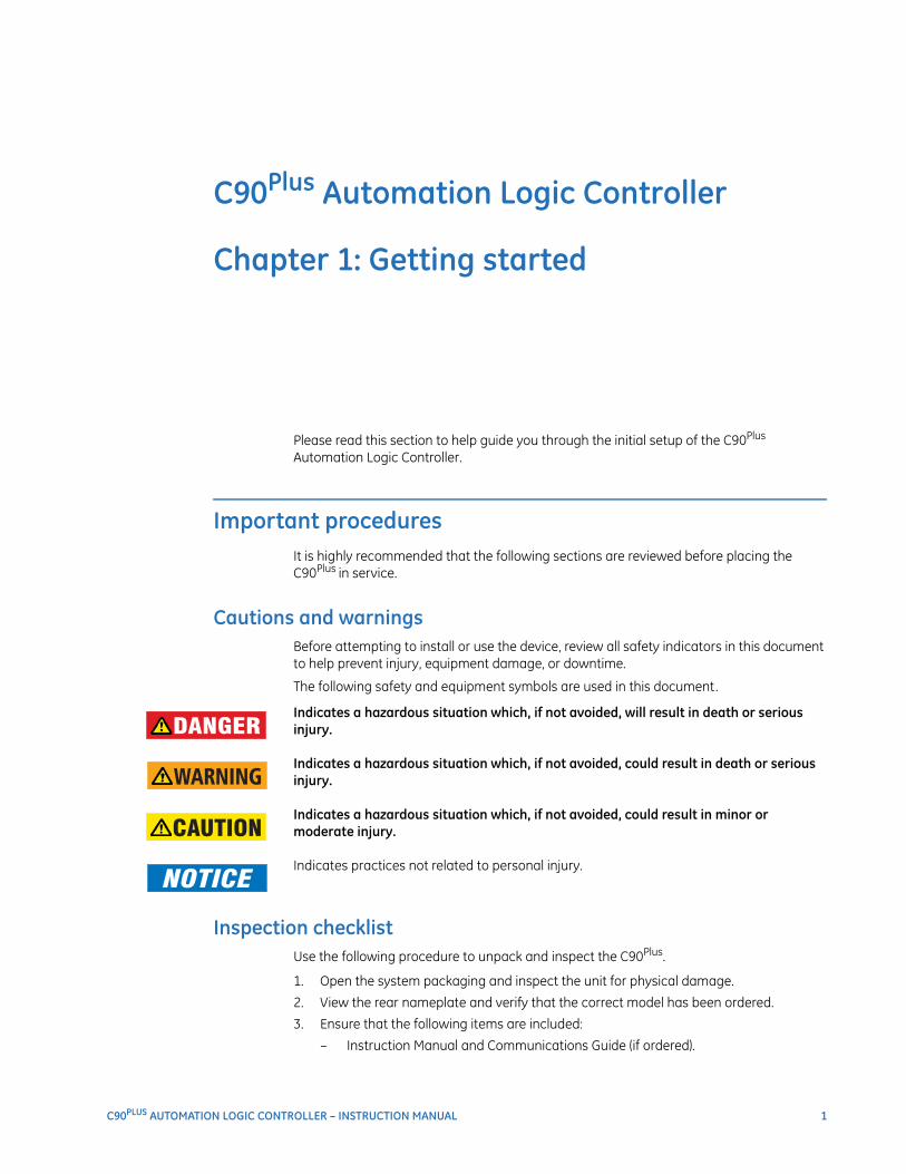
Cautions and warningsBefore attempting to install or use the device, review all safety indicators in this document to help prevent injury, equipment damage, or downtime.
The following safety and equipment symbols are used in this document.DANGER: Indicates a hazardous situation which, if not avoided, will result in death or serious
injury.
IMPORTANT: Indicates a hazardous situation which, if not avoided, could result in death or serious injury.
CAUTION: Indicates a hazardous situation which, if not avoided, could result in minor or moderate injury.
FASTPATH: Indicates practices not related to personal injury.
Inspection checklistUse the following procedure to unpack and inspect the C90Plus.
1. Open the system packaging and inspect the unit for physical damage.
2. View the rear nameplate and verify that the correct model has been ordered.
3. Ensure that the following items are included:
– Instruction Manual and Communications Guide (if ordered).
2 C90PLUS AUTOMATION LOGIC CONTROLLER – INSTRUCTION MANUAL
INTRODUCTION TO THE URPlus-SERIES CHAPTER 1: GETTING STARTED
– GE EnerVista CD (includes software and documentation).
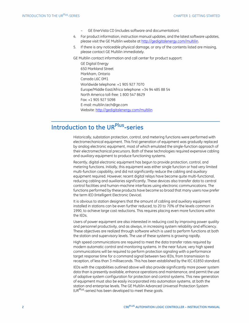
4. For product information, instruction manual updates, and the latest software updates, please visit the GE Multilin website at http://gedigitalenergy.com/multilin.
5. If there is any noticeable physical damage, or any of the contents listed are missing, please contact GE Multilin immediately.
GE Multilin contact information and call center for product support:GE Digital Energy650 Markland StreetMarkham, OntarioCanada L6C 0M1Worldwide telephone: +1 905 927 7070Europe/Middle East/Africa telephone: +34 94 485 88 54North America toll-free: 1 800 547 8629Fax: +1 905 927 5098E-mail: [email protected]: http://gedigitalenergy.com/multilin
Introduction to the URPlus-seriesHistorically, substation protection, control, and metering functions were performed with electromechanical equipment. This first generation of equipment was gradually replaced by analog electronic equipment, most of which emulated the single-function approach of their electromechanical precursors. Both of these technologies required expensive cabling and auxiliary equipment to produce functioning systems.
Recently, digital electronic equipment has begun to provide protection, control, and metering functions. Initially, this equipment was either single function or had very limited multi-function capability, and did not significantly reduce the cabling and auxiliary equipment required. However, recent digital relays have become quite multi-functional, reducing cabling and auxiliaries significantly. These devices also transfer data to central control facilities and human-machine interfaces using electronic communications. The functions performed by these products have become so broad that many users now prefer the term IED (Intelligent Electronic Device).
It is obvious to station designers that the amount of cabling and auxiliary equipment installed in stations can be even further reduced, to 20 to 70% of the levels common in 1990, to achieve large cost reductions. This requires placing even more functions within the IEDs.
Users of power equipment are also interested in reducing cost by improving power quality and personnel productivity, and as always, in increasing system reliability and efficiency. These objectives are realized through software which is used to perform functions at both the station and supervisory levels. The use of these systems is growing rapidly.
High speed communications are required to meet the data transfer rates required by modern automatic control and monitoring systems. In the near future, very high speed communications will be required to perform protection signaling with a performance target response time for a command signal between two IEDs, from transmission to reception, of less than 3 milliseconds. This has been established by the IEC 61850 standard.
IEDs with the capabilities outlined above will also provide significantly more power system data than is presently available, enhance operations and maintenance, and permit the use of adaptive system configuration for protection and control systems. This new generation of equipment must also be easily incorporated into automation systems, at both the station and enterprise levels. The GE Multilin Advanced Universal Protection System (URPlus-series) has been developed to meet these goals.

CHAPTER 1: GETTING STARTED INTRODUCTION TO THE URPlus-SERIES
C90PLUS AUTOMATION LOGIC CONTROLLER – INSTRUCTION MANUAL 3
The C90Plus is the advanced automation controller for the URPlus-series platform.
Hardware architectureThe C90Plus is a microprocessor-based device. It has a modular design consisting of a chassis containing discrete modules that interface over a common bus. Each module is dedicated to a specific purpose. Several of the modules are required for basic operation of the device, while others are optional.
The power supply module receives AC or DC power from an external supply and produces conditioned 12 V DC power for all of the modules in the chassis. The power supply also generates 48 V DC power for external contact wetting. The output contact indicating a critical failure of the unit also resides on this module.
The AC module measures AC currents and voltages derived from CTs and VTs. These signals are sampled and digitized and sent over the C90Plus bus to the CPU module for further processing. A version is available that accepts nominal 5 A current and another that accepts nominal 1 A current.
Input and output modules monitor digital (on and off) signals from external devices (field contacts or other IEDs), control external devices such as breakers, and send digital signals to other devices. Input and output modules are subdivided into protection inputs and outputs and automation inputs and outputs, with several flavors of each type.
The CPU module contains the firmware for the C90Plus. The firmware contains the algorithms required for the various functions provided by the device. The CPU receives analog and digital data from the AC and input/output modules. The data is processed by the CPU and resulting control actions are sent back to the input-output modules. The CPU has one rear Ethernet port that is used for configuration and record retrieval and one rear RS485 port supporting the Modbus and DNP protocols. The CPU also contains the IRIG-B port required for clock synchronization.
The communications module is required for communicating with external devices over Ethernet using the IEC 61850, DNP 3.0, or IEC60870-5-104 protocols. This module is also required for peer-to-peer GSSE/GOOSE messaging. This module contains its own microprocessor which is dedicated to handling communications tasks. It also contains two redundant Ethernet ports. Each port supports 100Base-FX over multi-mode fiber and 10/100Base-TX over twisted pair, with auto-negotiation. These ports may additionally be configured for single IP or dual IP redundancy.
NOTE
NOTE: The C90Plus requires one power supply module, one CPU module, one AC module, and at least one protection input/output module. Communications modules are optional.
The front panel interface consists of an annunciator display, a main display, and an EnerVista USB port. The annunciator display collects alarm indications from the C90Plus internal functions and presents them using a standard annunciator format. Alarms and their corresponding messages are entirely user-configurable. The main display allows the user to view metering data collected by the C90Plus. It also provides access to the control functions via dedicated control pushbuttons. The USB port allows the user to interface with the C90Plus using the EnerVista software running on a portable PC. The C90Plus operates independently from the front panel interface.
4 C90PLUS AUTOMATION LOGIC CONTROLLER – INSTRUCTION MANUAL
INTRODUCTION TO THE URPlus-SERIES CHAPTER 1: GETTING STARTED
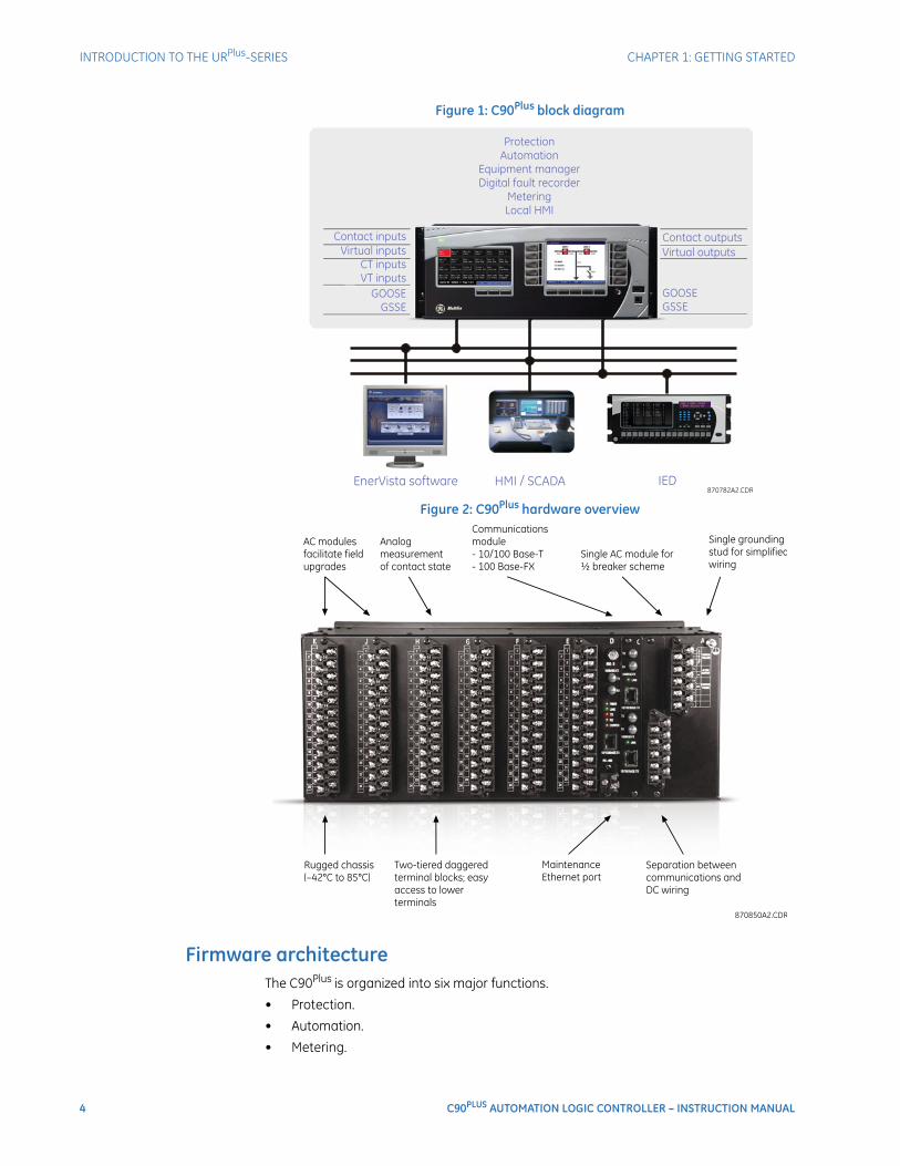
Figure 1: C90Plus block diagram
Figure 2: C90Plus hardware overview
Firmware architectureThe C90Plus is organized into six major functions.
• Protection.
• Automation.
• Metering.

CHAPTER 1: GETTING STARTED INTRODUCTION TO THE URPlus-SERIES
C90PLUS AUTOMATION LOGIC CONTROLLER – INSTRUCTION MANUAL 5
• Digital fault recorder (DFR).
• Equipment manager.
• Front panel interface (HMI).
These functions operate autonomously from one another. Each function has its own configuration parameters and each generates it own output signals. All functions share the hardware and the communications facilities within the device.
The protection function contains the necessary elements required to detect faults in the power system and send tripping signals to isolate the fault. This will be the primary sub-system for many users. The protection function also has its own dedicated FlexLogic™ engine which runs at the same scan rate as the protection (16 times per power system cycle). Protection FlexLogic™ is used to create custom logic schemes for protection purposes.
Automation is divided into two major sub-groupings: control schemes and automation logic. Control schemes are hard-coded general purpose schemes responsible for automatic control within the substation. These include breaker and disconnect switch control, interlocking, and synchrocheck. Automation logic is intended for development of custom or advanced automatic schemes in the case the user requires a level of functionality beyond that found in the hard-coded schemes. Automation logic generally requires a lower execution rate than protection logic but has greatly expanded functionality and lines of logic.
The metering function generates a wide range of real-time power system measurements including voltage, current, frequency, complex power, and energy. It also incorporates a data logger that provides historical recording of selected metering quantities and includes statistical (maximum, minimum, and average) and alarming capabilities. The metering function also provides synchrophasor capabilities in accordance with IEEE C37.118-2005.
The digital fault recorder incorporates transient recorder, disturbance recorder and fault report capabilities. The transient recorder is intended to capture short events such as a fault at a high sampling rate (up to 256 samples per cycle). The disturbance recorder captures longer events such as a power swing at a lower sampling rate. The channel assignments and triggering of these features can be independently configured. The fault report facility provides a comprehensive record of the key measurements associated with an event including fault type, fault location, pre-fault and post-fault quantities, and clearing time.
The equipment manager function monitors important parameters of the station battery under normal operation and can be used to detect incipient failures.
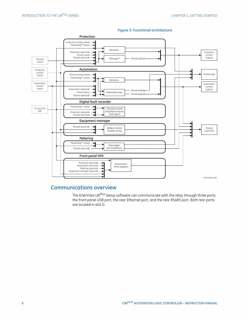
Despite their logic separation, signals can be exchanged between these functions. For instance, it is useful for the digital fault recorder to record the output of protection functions. Consequently a fixed, pre-determined set of signals is available as inputs to each function. These are illustrated in the following figure.
The C90Plus also includes shared operand functionality. Output signals from the various functions can be assigned as shared operands available to all functions. These signals can then be assigned as inputs within other functions.
For example, assume that the PHASE TOC1 OP protection FlexLogic™ operand is required as a signal within the automation function. This signal would be assigned as a shared operand. As such, the PHASE TOC1 OP operand would subsequently become available to the automation function by appearing in the list of available operands.
6 C90PLUS AUTOMATION LOGIC CONTROLLER – INSTRUCTION MANUAL
INTRODUCTION TO THE URPlus-SERIES CHAPTER 1: GETTING STARTED
Figure 3: Functional architecture
Communications overviewThe EnerVista URPlus Setup software can communicate with the relay through three ports: the front panel USB port, the rear Ethernet port, and the rear RS485 port. Both rear ports are located in slot D.
CHAPTER 1: GETTING STARTED ENERVISTA SOFTWARE
C90PLUS AUTOMATION LOGIC CONTROLLER – INSTRUCTION MANUAL 7
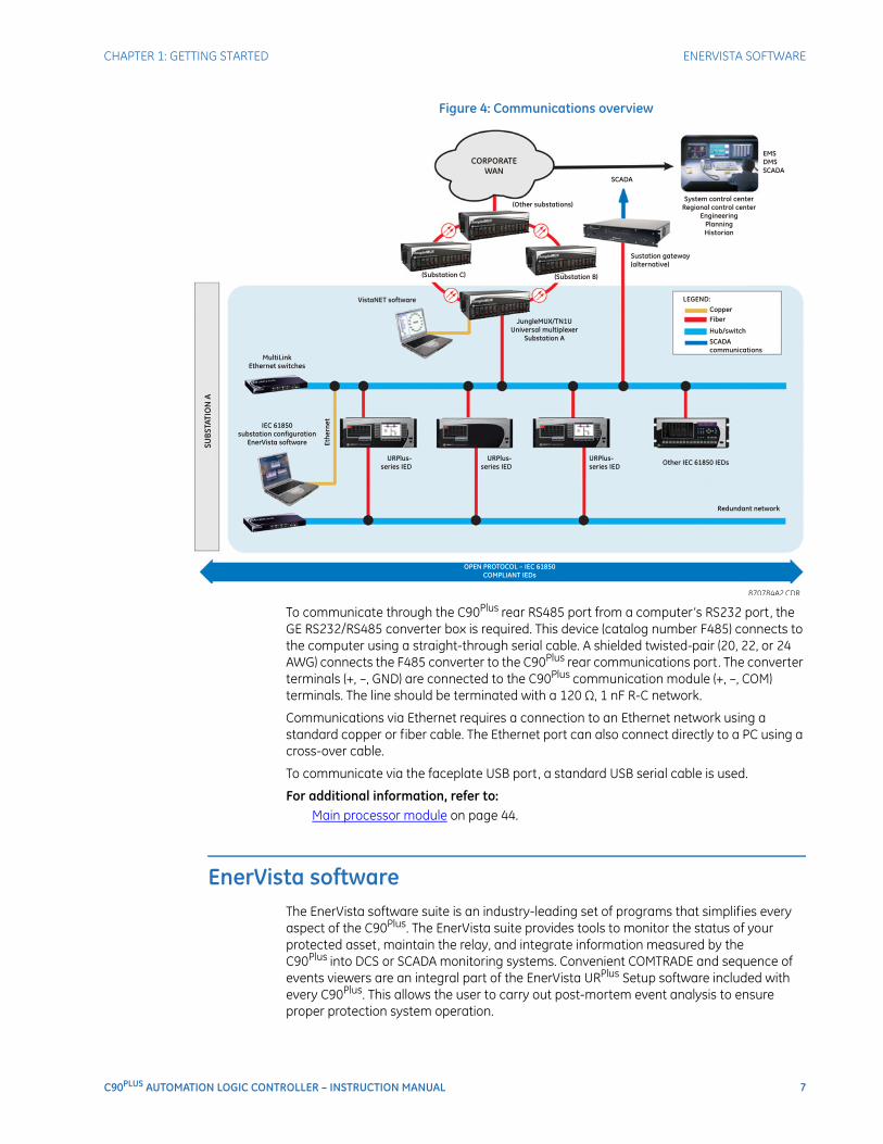
Figure 4: Communications overview
To communicate through the C90Plus rear RS485 port from a computer’s RS232 port, the GE RS232/RS485 converter box is required. This device (catalog number F485) connects to the computer using a straight-through serial cable. A shielded twisted-pair (20, 22, or 24 AWG) connects the F485 converter to the C90Plus rear communications port. The converter terminals (+, –, GND) are connected to the C90Plus communication module (+, –, COM) terminals. The line should be terminated with a 120 Ω, 1 nF R-C network.
Communications via Ethernet requires a connection to an Ethernet network using a standard copper or fiber cable. The Ethernet port can also connect directly to a PC using a cross-over cable.
To communicate via the faceplate USB port, a standard USB serial cable is used.
For additional information, refer to:Main processor module on page 44.
EnerVista softwareThe EnerVista software suite is an industry-leading set of programs that simplifies every aspect of the C90Plus. The EnerVista suite provides tools to monitor the status of your protected asset, maintain the relay, and integrate information measured by the C90Plus into DCS or SCADA monitoring systems. Convenient COMTRADE and sequence of events viewers are an integral part of the EnerVista URPlus Setup software included with every C90Plus. This allows the user to carry out post-mortem event analysis to ensure proper protection system operation.
8 C90PLUS AUTOMATION LOGIC CONTROLLER – INSTRUCTION MANUAL
ENERVISTA SOFTWARE CHAPTER 1: GETTING STARTED
Software requirementsThe EnerVista URPlus Setup software interface is used to communicate with the C90Plus. The EnerVista URPlus Setup software interface is the preferred method to edit settings and view actual values because the PC monitor can display more information in a simple comprehensible format.
The following minimum requirements must be met for the EnerVista URPlus Setup software to properly operate on a PC.
• Pentium class or higher processor (Pentium II 300 MHz or higher recommended).
• Windows 2000, XP, or Vista.
• Internet Explorer 4.0 or higher.
• 128 MB of RAM (256 MB recommended).
• 200 MB of available space on system drive and 200 MB of available space on installation drive.
• Video capable of displaying 800 × 600 or higher in high-color mode (16-bit color).
• USB 2.0 or Ethernet port for communications to the IED.
Installing the EnerVista URPlus Setup softwareAfter ensuring the minimum requirements for using EnerVista URPlus Setup software (see previous section), use the following procedure to install the EnerVista URPlus Setup from the enclosed GE EnerVista CD.
1. Insert the GE EnerVista CD into your CD-ROM drive.
2. Click the Install Now button and follow the installation instructions to install the no-charge EnerVista software.
3. When installation is complete, start the EnerVista Launchpad application.
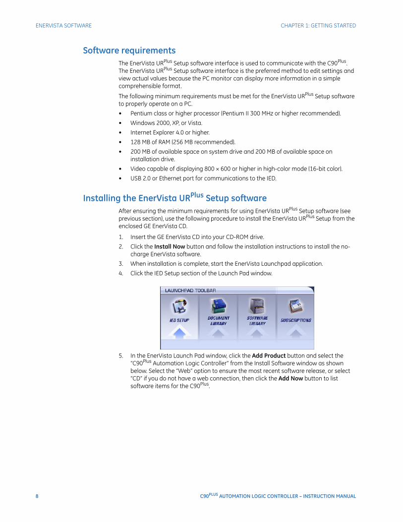
4. Click the IED Setup section of the Launch Pad window.
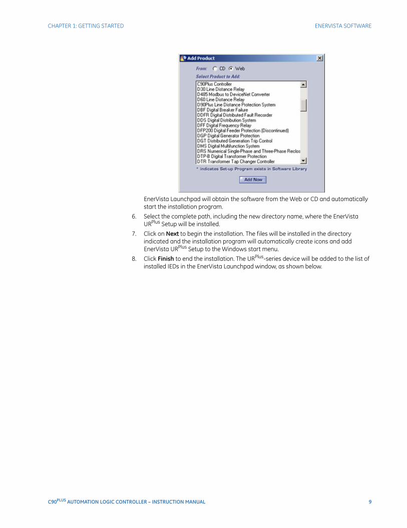
5. In the EnerVista Launch Pad window, click the Add Product button and select the “C90Plus Automation Logic Controller” from the Install Software window as shown below. Select the “Web” option to ensure the most recent software release, or select “CD” if you do not have a web connection, then click the Add Now button to list software items for the C90Plus.
CHAPTER 1: GETTING STARTED ENERVISTA SOFTWARE
C90PLUS AUTOMATION LOGIC CONTROLLER – INSTRUCTION MANUAL 9
EnerVista Launchpad will obtain the software from the Web or CD and automatically start the installation program.
6. Select the complete path, including the new directory name, where the EnerVista URPlus Setup will be installed.
7. Click on Next to begin the installation. The files will be installed in the directory indicated and the installation program will automatically create icons and add EnerVista URPlus Setup to the Windows start menu.
8. Click Finish to end the installation. The URPlus-series device will be added to the list of installed IEDs in the EnerVista Launchpad window, as shown below.
10 C90PLUS AUTOMATION LOGIC CONTROLLER – INSTRUCTION MANUAL
ENERVISTA SOFTWARE CHAPTER 1: GETTING STARTED
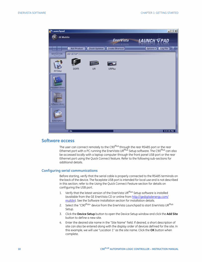
Software accessThe user can connect remotely to the C90Plus through the rear RS485 port or the rear Ethernet port with a PC running the EnerVista URPlus Setup software. The C90Plus can also be accessed locally with a laptop computer through the front panel USB port or the rear Ethernet port using the Quick Connect feature. Refer to the following sub-sections for additional details.
Configuring serial communicationsBefore starting, verify that the serial cable is properly connected to the RS485 terminals on the back of the device. The faceplate USB port is intended for local use and is not described in this section; refer to the Using the Quick Connect Feature section for details on configuring the USB port.
1. Verify that the latest version of the EnerVista URPlus Setup software is installed (available from the GE EnerVista CD or online from http://gedigitalenergy.com/multilin). See the Software Installation section for installation details.
2. Select the “C90Plus” device from the EnerVista Launchpad to start EnerVista URPlus Setup.
3. Click the Device Setup button to open the Device Setup window and click the Add Site button to define a new site.
4. Enter the desired site name in the “Site Name” field. If desired, a short description of site can also be entered along with the display order of devices defined for the site. In this example, we will use “Location 1” as the site name. Click the OK button when complete.
CHAPTER 1: GETTING STARTED ENERVISTA SOFTWARE
C90PLUS AUTOMATION LOGIC CONTROLLER – INSTRUCTION MANUAL 11
5. The new site will appear in the upper-left list in the EnerVista URPlus Setup window. Click the Device Setup button then select the new site to re-open the Device Setup window.
6. Click the Add Device button to define the new device.
7. Enter the desired name in the “Device Name” field and a description (optional) of the site.
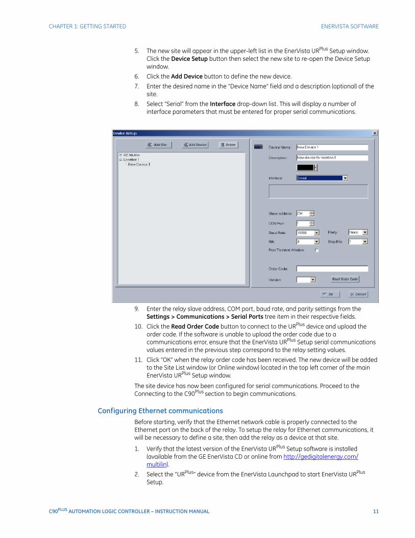
8. Select “Serial” from the Interface drop-down list. This will display a number of interface parameters that must be entered for proper serial communications.
9. Enter the relay slave address, COM port, baud rate, and parity settings from the Settings > Communications > Serial Ports tree item in their respective fields.
10. Click the Read Order Code button to connect to the URPlus device and upload the order code. If the software is unable to upload the order code due to a communications error, ensure that the EnerVista URPlus Setup serial communications values entered in the previous step correspond to the relay setting values.
11. Click “OK” when the relay order code has been received. The new device will be added to the Site List window (or Online window) located in the top left corner of the main EnerVista URPlus Setup window.
The site device has now been configured for serial communications. Proceed to the Connecting to the C90Plus section to begin communications.
Configuring Ethernet communicationsBefore starting, verify that the Ethernet network cable is properly connected to the Ethernet port on the back of the relay. To setup the relay for Ethernet communications, it will be necessary to define a site, then add the relay as a device at that site.
1. Verify that the latest version of the EnerVista URPlus Setup software is installed (available from the GE EnerVista CD or online from http://gedigitalenergy.com/multilin).
2. Select the “URPlus” device from the EnerVista Launchpad to start EnerVista URPlus Setup.
12 C90PLUS AUTOMATION LOGIC CONTROLLER – INSTRUCTION MANUAL
ENERVISTA SOFTWARE CHAPTER 1: GETTING STARTED
3. Click the Device Setup button to open the Device Setup window, then click the Add Site button to define a new site.
4. Enter the desired site name in the “Site Name” field.
If desired, a short description of site can also be entered along with the display order of devices defined for the site. In this example, we will use “Location 2” as the site name.
5. Click the OK button when complete.
The new site will appear in the upper-left list in the EnerVista URPlus Setup window.
6. Click the Device Setup button then select the new site to re-open the Device Setup window.
7. Click the Add Device button to define the new device.
8. Enter the desired name in the “Device Name” field and a description (optional) of the site.
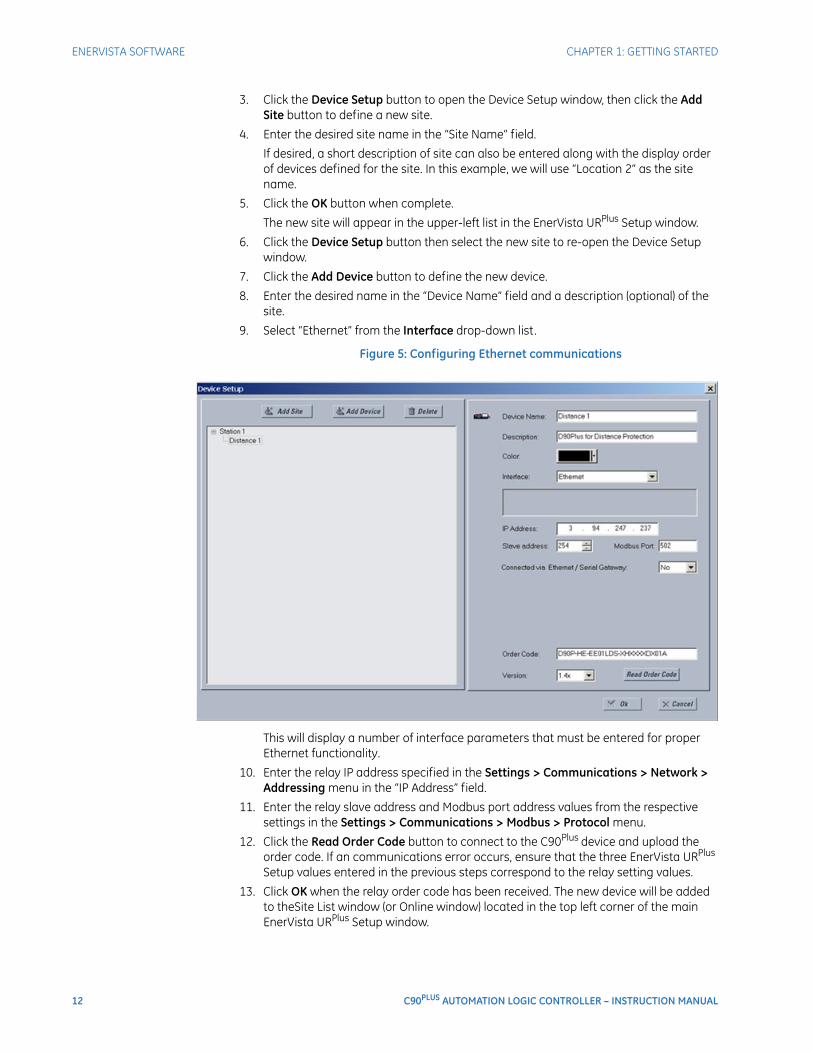
9. Select “Ethernet” from the Interface drop-down list.
Figure 5: Configuring Ethernet communications
This will display a number of interface parameters that must be entered for proper Ethernet functionality.
10. Enter the relay IP address specified in the Settings > Communications > Network > Addressing menu in the “IP Address” field.
11. Enter the relay slave address and Modbus port address values from the respective settings in the Settings > Communications > Modbus > Protocol menu.
12. Click the Read Order Code button to connect to the C90Plus device and upload the order code. If an communications error occurs, ensure that the three EnerVista URPlus Setup values entered in the previous steps correspond to the relay setting values.
13. Click OK when the relay order code has been received. The new device will be added to theSite List window (or Online window) located in the top left corner of the main EnerVista URPlus Setup window.
CHAPTER 1: GETTING STARTED ENERVISTA SOFTWARE
C90PLUS AUTOMATION LOGIC CONTROLLER – INSTRUCTION MANUAL 13
The site device has now been configured for Ethernet communications. Proceed to the Connecting to the C90Plus section to begin communications.
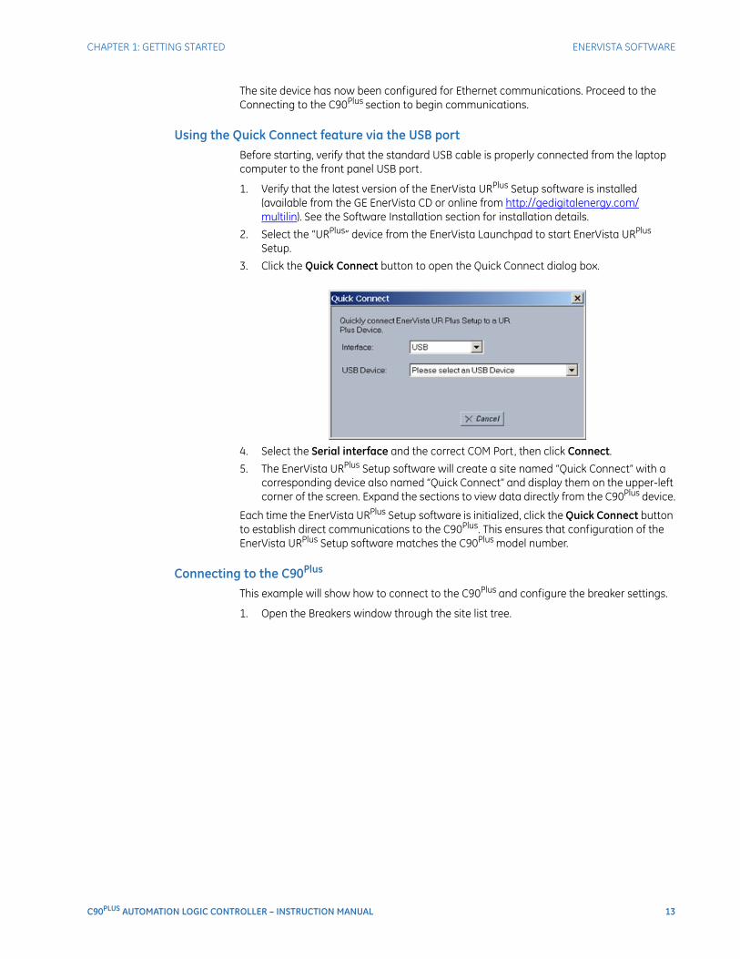
Using the Quick Connect feature via the USB portBefore starting, verify that the standard USB cable is properly connected from the laptop computer to the front panel USB port.
1. Verify that the latest version of the EnerVista URPlus Setup software is installed (available from the GE EnerVista CD or online from http://gedigitalenergy.com/multilin). See the Software Installation section for installation details.
2. Select the “URPlus” device from the EnerVista Launchpad to start EnerVista URPlus Setup.
3. Click the Quick Connect button to open the Quick Connect dialog box.
4. Select the Serial interface and the correct COM Port, then click Connect.
5. The EnerVista URPlus Setup software will create a site named “Quick Connect” with a corresponding device also named “Quick Connect” and display them on the upper-left corner of the screen. Expand the sections to view data directly from the C90Plus device.
Each time the EnerVista URPlus Setup software is initialized, click the Quick Connect button to establish direct communications to the C90Plus. This ensures that configuration of the EnerVista URPlus Setup software matches the C90Plus model number.
Connecting to the C90Plus
This example will show how to connect to the C90Plus and configure the breaker settings.
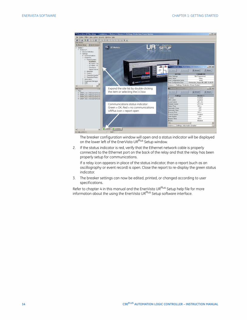
1. Open the Breakers window through the site list tree.
14 C90PLUS AUTOMATION LOGIC CONTROLLER – INSTRUCTION MANUAL
ENERVISTA SOFTWARE CHAPTER 1: GETTING STARTED
The breaker configuration window will open and a status indicator will be displayed on the lower left of the EnerVista URPlus Setup window.
2. If the status indicator is red, verify that the Ethernet network cable is properly connected to the Ethernet port on the back of the relay and that the relay has been properly setup for communications.
If a relay icon appears in place of the status indicator, than a report (such as an oscillography or event record) is open. Close the report to re-display the green status indicator.
3. The breaker settings can now be edited, printed, or changed according to user specifications.
Refer to chapter 4 in this manual and the EnerVista URPlus Setup help file for more information about the using the EnerVista URPlus Setup software interface.
C90PLUS AUTOMATION LOGIC CONTROLLER – INSTRUCTION MANUAL 15
C90Plus Automation Logic Controller
Chapter 2: Product description
Product description
This section provides a basic functional overview and the technical specifications for the C90Plus.
C90Plus overviewThe C90Plus Automation Logic Controller is a powerful logic controller specifically designed for use in substation environments and for the unique automation requirements of industrial and utility power systems. The C90Plus provides unmatched logic processing ability combined with a powerful math engine with deterministic execution of logic equations regardless of the configuration of the number of lines of logic.
The C90Plus provides the tools and functionality necessary for creating customized automation and control schemes that include:
• Advanced bay control and interlocking.
• Breaker monitoring and control.
• Automatic bus transfer schemes.
• Load shedding and load restoration schemes.
Additional key benefits of the C90Plus are listed below.
• Deterministic execution of logic regardless of the number of configured equations.
• Substation hardened controller that surpasses the transient, ESD, and RFI immunity of a standard PLC.
• Local front panel interface provides real time control and annunciation of station events.
• Configurable alarm annunciator eliminates the need for separate annunciator panel.
• Intuitive and easy-to-use large front panel color display with pre-configured information on metering, fault records, event records, and separate control screen for bay control.
• High-end fault and disturbance recording, including internal relay operating signals, eliminating the need for redundant recording devices.
• Reduced installation space requirements through compact design.
• True convergence of protection, metering, automation, control functions, multiple input and output options, and extensive communications capability.
16 C90PLUS AUTOMATION LOGIC CONTROLLER – INSTRUCTION MANUAL
C90Plus OVERVIEW CHAPTER 2: PRODUCT DESCRIPTION
Front panel interfaceAn intuitive and easy-to-use color graphical display is provided in the C90Plus front panel. The display provides easy access and visualization of device information, ranging from the large display of metered values such as voltage, current, demand, energy, and sequence components, to a comprehensive display of fault reports, sequence of events, and transient recorded waveforms. The front panel interface also displays device health information with critical and non-critical alarm status.
This advanced functionality allows the user to access comprehensive information without having to navigate through conventional displays and keypads. Information is displayed through two dedicated display panels. One serves as a digital annunciator and the other reflects display and control functions.
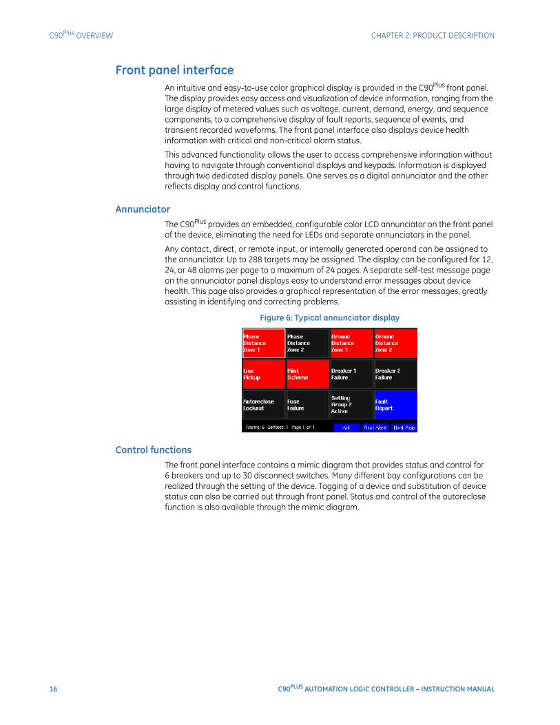
AnnunciatorThe C90Plus provides an embedded, configurable color LCD annunciator on the front panel of the device, eliminating the need for LEDs and separate annunciators in the panel.
Any contact, direct, or remote input, or internally generated operand can be assigned to the annunciator. Up to 288 targets may be assigned. The display can be configured for 12, 24, or 48 alarms per page to a maximum of 24 pages. A separate self-test message page on the annunciator panel displays easy to understand error messages about device health. This page also provides a graphical representation of the error messages, greatly assisting in identifying and correcting problems.
Figure 6: Typical annunciator display
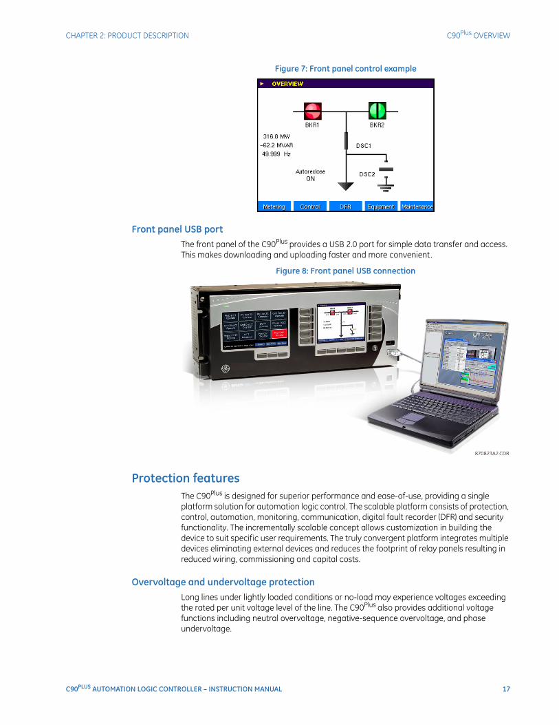
Control functionsThe front panel interface contains a mimic diagram that provides status and control for 6 breakers and up to 30 disconnect switches. Many different bay configurations can be realized through the setting of the device. Tagging of a device and substitution of device status can also be carried out through front panel. Status and control of the autoreclose function is also available through the mimic diagram.
CHAPTER 2: PRODUCT DESCRIPTION C90Plus OVERVIEW
C90PLUS AUTOMATION LOGIC CONTROLLER – INSTRUCTION MANUAL 17
Figure 7: Front panel control example
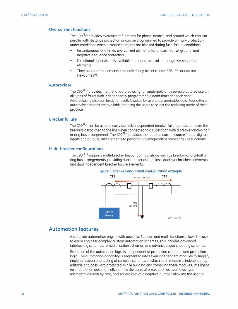
Front panel USB portThe front panel of the C90Plus provides a USB 2.0 port for simple data transfer and access. This makes downloading and uploading faster and more convenient.
Figure 8: Front panel USB connection
Protection featuresThe C90Plus is designed for superior performance and ease-of-use, providing a single platform solution for automation logic control. The scalable platform consists of protection, control, automation, monitoring, communication, digital fault recorder (DFR) and security functionality. The incrementally scalable concept allows customization in building the device to suit specific user requirements. The truly convergent platform integrates multiple devices eliminating external devices and reduces the footprint of relay panels resulting in reduced wiring, commissioning and capital costs.
Overvoltage and undervoltage protectionLong lines under lightly loaded conditions or no-load may experience voltages exceeding the rated per unit voltage level of the line. The C90Plus also provides additional voltage functions including neutral overvoltage, negative-sequence overvoltage, and phase undervoltage.
18 C90PLUS AUTOMATION LOGIC CONTROLLER – INSTRUCTION MANUAL
C90Plus OVERVIEW CHAPTER 2: PRODUCT DESCRIPTION
Overcurrent functionsThe C90Plus provides overcurrent functions for phase, neutral, and ground which can run parallel with distance protection or can be programmed to provide primary protection under conditions when distance elements are blocked during fuse-failure conditions.
• Instantaneous and timed overcurrent elements for phase, neutral, ground, and negative-sequence protection.
• Directional supervision is available for phase, neutral, and negative-sequence elements.
• Time overcurrent elements can individually be set to use IEEE, IEC, or custom FlexCurves™.
AutorecloseThe C90Plus provides multi-shot autoreclosing for single-pole or three-pole autoreclose on all types of faults with independently programmable dead times for each shot. Autoreclosing also can be dynamically blocked by user programmable logic. Four different autoreclose modes are available enabling the users to select the reclosing mode of their practice.
Breaker failureThe C90Plus can be used to carry out fully independent breaker failure protection over the breakers associated to the line when connected to a substation with a breaker-and-a-half or ring bus arrangement. The C90Plus provides the required current source inputs, digital inputs and outputs, and elements to perform two independent breaker failure functions.
Multi-breaker configurationsThe C90Plus supports multi-breaker busbar configurations such as breaker-and-a-half or ring bus arrangements, providing dual breaker autoreclose, dual synchrocheck elements, and dual independent breaker failure elements.
Figure 9: Breaker-and-a-half configuration example
Automation featuresA separate automation engine with powerful Boolean and math functions allows the user to easily engineer complex custom automation schemes. This includes advanced interlocking schemes, remedial action schemes, and advanced load shedding schemes.
Execution of the automation logic is independent of protection elements and protection logic. The automation capability is segmented into seven independent modules to simplify implementation and testing of complex schemes in which each module is independently editable and password protected. While building and compiling these modules, intelligent error detection automatically notifies the users of errors such as overflows, type mismatch, division by zero, and square root of a negative number, allowing the user to

CHAPTER 2: PRODUCT DESCRIPTION C90Plus OVERVIEW
C90PLUS AUTOMATION LOGIC CONTROLLER – INSTRUCTION MANUAL 19
achieve maximum optimization. The programming interface complies with the global standard IEC 61131 for industrial control programming and also allows for embedded comments. Easy to use on-line and off-line debugging and simulation tools provide extensive testing capabilities of complex schemes. This includes forcing of input variables, simulation of analog values and visualization of live logic states and live analog values.
Synchrocheck and breaker control, disconnect switch control, and local/remote breaker control are available as hard-coded schemes as part of the C90Plus automation capabilities.
Synchronism checkThe synchrocheck elements are typically used at locations where the two parts of the system are interconnected through at least one other point in the system, which are to be joined by the closure of one or more circuit breakers. The C90Plus provides the required voltage source inputs, digital inputs and outputs, and elements to monitor differences in voltage magnitudes, phase angles, and frequencies to perform synchronism check across two breakers. The C90Plus can be used to carry out full independent control over the breakers associated to the line when connected to a substation with a breaker-and-a-half or ring bus arrangement.
Scalable hardwareThe C90Plus is available with a multitude of input and output configurations to suit the most demanding application needs. The expandable modular design allows for easy configuration and future upgrades. Types of digital outputs include trip-rated form-A and solid-state (SSR) relays available with optional circuit continuity monitoring and current detection to verify continuity and health of the associated circuitry.
Equipment manager featuresCritical assets, such as circuit breakers and the station battery, are monitored with the powerful C90Plus condition monitoring and diagnostic features. The C90Plus processes the interrupted current of the breaker, the auxiliary contact status of the breakers, spring compressor operating time and frequency, compressor motor current, SF6 pressure stages and the circuit breaker trip and close coil monitoring to alert the operator an impending circuit breaker problem. Up to two breakers, associated trip, close coils and station battery can be monitored in real time. These features are available through the front panel interface in real time allowing the operating personnel to detect any abnormality and take corrective actions. A comprehensive equipment-monitoring feature of C90Plus reduces the downtime of your assets and improves the availability of the power system.
NOTE
NOTE: Only the battery monitor and breaker arcing current features are supported in the current version of the C90Plus.
20 C90PLUS AUTOMATION LOGIC CONTROLLER – INSTRUCTION MANUAL
C90Plus OVERVIEW CHAPTER 2: PRODUCT DESCRIPTION
Figure 10: Circuit breaker monitoring example
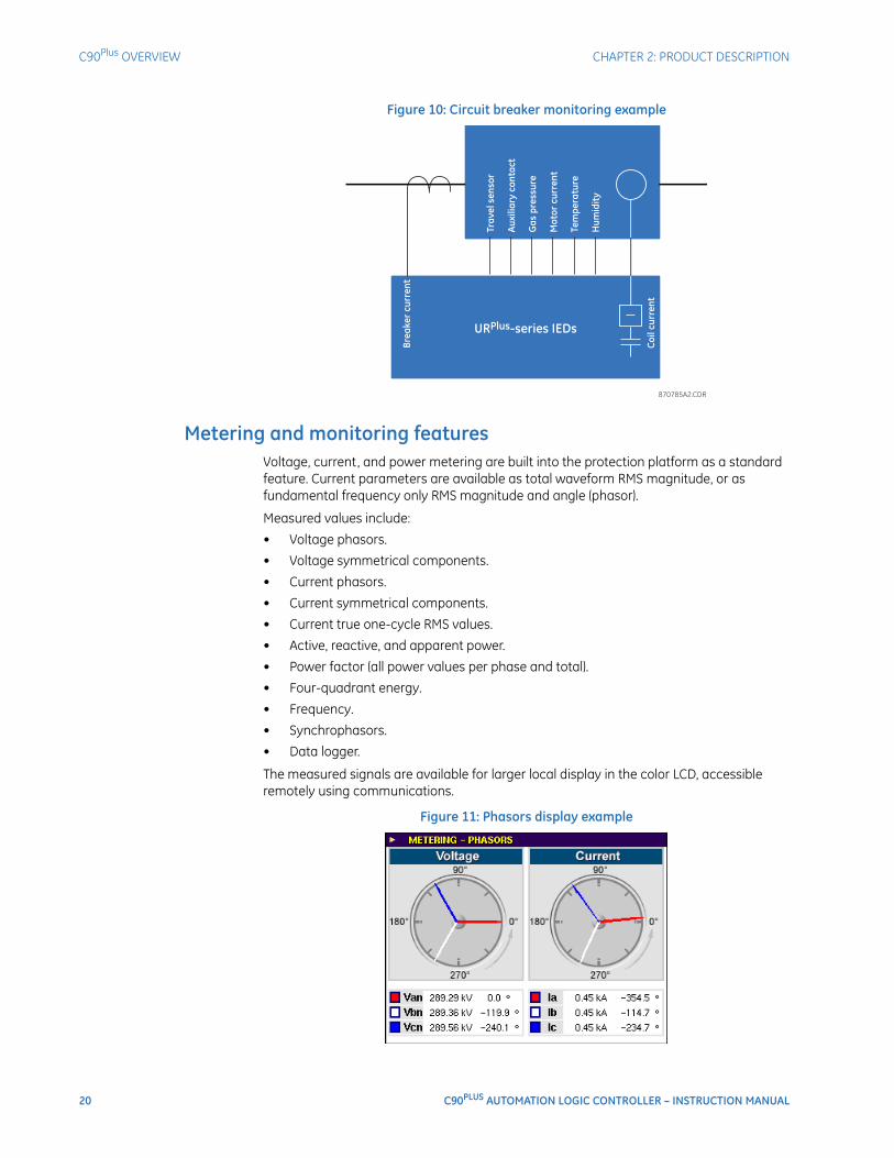
Metering and monitoring featuresVoltage, current, and power metering are built into the protection platform as a standard feature. Current parameters are available as total waveform RMS magnitude, or as fundamental frequency only RMS magnitude and angle (phasor).
Measured values include:
• Voltage phasors.
• Voltage symmetrical components.
• Current phasors.
• Current symmetrical components.
• Current true one-cycle RMS values.
• Active, reactive, and apparent power.
• Power factor (all power values per phase and total).
• Four-quadrant energy.
• Frequency.
• Synchrophasors.
• Data logger.
The measured signals are available for larger local display in the color LCD, accessible remotely using communications.
Figure 11: Phasors display example
CHAPTER 2: PRODUCT DESCRIPTION C90Plus OVERVIEW
C90PLUS AUTOMATION LOGIC CONTROLLER – INSTRUCTION MANUAL 21
Energy meteringThe metered values for real, reactive, and apparent power, as well as power factor, are displayed via the front panel interface or through the EnerVista URPlus Setup software.
PhasorsThe metered values and phasor representations for phase current, ground current, phase voltage, and auxiliary voltage are displayed via the front panel interface or through the EnerVista URPlus Setup software.
Sequence components meteringThe metered values and phasor representations for negative-sequence current and voltage, positive-sequence current and voltage, and zero-sequence current and voltage are displayed via the front panel interface or through the EnerVista URPlus Setup software.
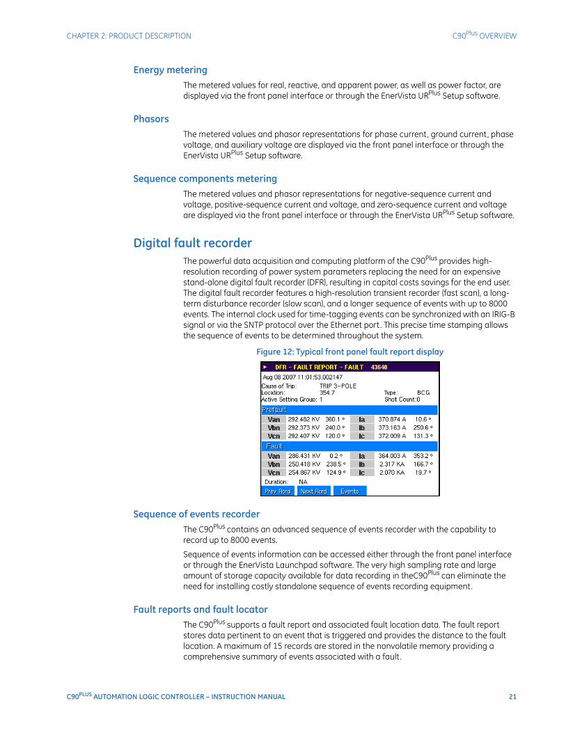
Digital fault recorderThe powerful data acquisition and computing platform of the C90Plus provides high-resolution recording of power system parameters replacing the need for an expensive stand-alone digital fault recorder (DFR), resulting in capital costs savings for the end user. The digital fault recorder features a high-resolution transient recorder (fast scan), a long-term disturbance recorder (slow scan), and a longer sequence of events with up to 8000 events. The internal clock used for time-tagging events can be synchronized with an IRIG-B signal or via the SNTP protocol over the Ethernet port. This precise time stamping allows the sequence of events to be determined throughout the system.
Figure 12: Typical front panel fault report display
Sequence of events recorderThe C90Plus contains an advanced sequence of events recorder with the capability to record up to 8000 events.
Sequence of events information can be accessed either through the front panel interface or through the EnerVista Launchpad software. The very high sampling rate and large amount of storage capacity available for data recording in theC90Plus can eliminate the need for installing costly standalone sequence of events recording equipment.
Fault reports and fault locatorThe C90Plus supports a fault report and associated fault location data. The fault report stores data pertinent to an event that is triggered and provides the distance to the fault location. A maximum of 15 records are stored in the nonvolatile memory providing a comprehensive summary of events associated with a fault.
22 C90PLUS AUTOMATION LOGIC CONTROLLER – INSTRUCTION MANUAL
ORDER CODES CHAPTER 2: PRODUCT DESCRIPTION
Transient recorderThe transient recorder captures critical system data during a transient event. It is tailored to capture shorter duration events such as faults at a high resolution. The transient recorder can be programmed to sample at 256 samples per cycle. The C90Plus can store up to 64 records in nonvolatile memory with up to one minute of storage capacity for all 16 analog channels and 128 digital channels. The transient recorder incorporates integrated triggering. Any monitored channel may be configured to trigger the recorder.
Disturbance recorderLonger-term events are monitored by disturbance recorders, which include voltage sag, swell and overloading. Any computed analog channel or digital channel can trigger the disturbance recorder. The C90Plus can store up to 64 records in nonvolatile memory with up to five minutes of storage capacity.
CommunicationsThe C90Plus incorporates powerful communications capabilities required for the demanding applications anticipated in future substations. The communications module is dedicated to processing the IEC 61850, DNP 3.0, and IEC 60870-5-104 protocols. This module provides redundant Ethernet ports each with 10/100Base-TX and 100Base-FX connectors.
Modbus RTU and DNP3.0 are also available as default protocols through the RS485 port or the CPU Ethernet ports (slot D).
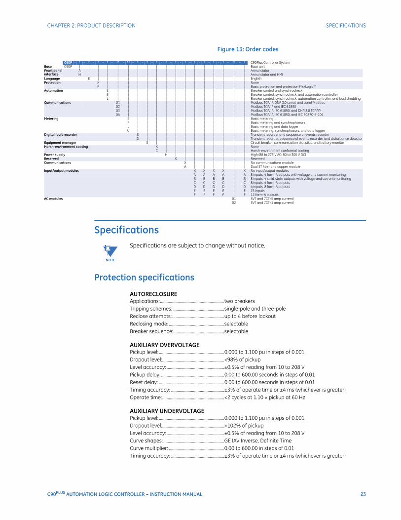
Order codesThe C90Plus is available as a 19-inch rack horizontal mount or reduced-size (¾) vertical unit and consists of a number of optional and required modules. Each of these modules can be supplied in a number of configurations specified at the time of ordering. The information required to completely specify the system is provided in the following table.
NOTE
NOTE: Order codes are subject to change without notice. See the ordering page at http://www.gedigitalenergy.com/multilin/order.htm for the latest details concerning C90Plus ordering options.
CHAPTER 2: PRODUCT DESCRIPTION SPECIFICATIONS
C90PLUS AUTOMATION LOGIC CONTROLLER – INSTRUCTION MANUAL 23
Figure 13: Order codes
Specifications
NOTE
NOTE: Specifications are subject to change without notice.
Protection specifications
AUTORECLOSUREApplications:..........................................................two breakersTripping schemes: ..............................................single-pole and three-poleReclose attempts: ...............................................up to 4 before lockoutReclosing mode: ..................................................selectableBreaker sequence:..............................................selectable
AUXILIARY OVERVOLTAGEPickup level: ...........................................................0.000 to 1.100 pu in steps of 0.001Dropout level:........................................................<98% of pickupLevel accuracy: ....................................................±0.5% of reading from 10 to 208 VPickup delay: .........................................................0.00 to 600.00 seconds in steps of 0.01Reset delay: ...........................................................0.00 to 600.00 seconds in steps of 0.01Timing accuracy: ................................................±3% of operate time or ±4 ms (whichever is greater)Operate time:........................................................<2 cycles at 1.10 × pickup at 60 Hz
AUXILIARY UNDERVOLTAGEPickup level: ...........................................................0.000 to 1.100 pu in steps of 0.001Dropout level:........................................................>102% of pickupLevel accuracy: ....................................................±0.5% of reading from 10 to 208 VCurve shapes: .......................................................GE IAV Inverse, Definite TimeCurve multiplier: ..................................................0.00 to 600.00 in steps of 0.01Timing accuracy: ................................................±3% of operate time or ±4 ms (whichever is greater)
C90P * * * * ** ** * * * * * * * * * * ** * C90Plus Controller SystemBase C90P | | | | | | | | | | | | | | | | | | Base unitFront panelinterface
A | | | | | | | | | | | | | | | | | AnnunciatorH | | | | | | | | | | | | | | | | | Annunciator and HMI
Language E | | | | | | | | | | | | | | | | EnglishProtection X | | | | | | | | | | | | | | | None
P | | | | | | | | | | | | | | | Basic protection and protection FlexLogicAutomation S | | | | | | | | | | | | | | Breaker control and synchrocheck
E | | | | | | | | | | | | | | Breaker control, synchrocheck, and automation controllerL | | | | | | | | | | | | | | Breaker control, synchrocheck, automation controller, and load shedding
Communications 01 | | | | | | | | | | | | | Modbus TCP/IP, DNP 3.0 serial, and serial Modbus02 | | | | | | | | | | | | | Modbus TCP/IP and IEC 6185003 | | | | | | | | | | | | | Modbus TCP/IP, IEC 61850, and DNP 3.0 TCP/IP04 | | | | | | | | | | | | | Modbus TCP/IP, IEC 61850, and IEC 60870-5-104
Metering S | | | | | | | | | | | | Basic meteringP | | | | | | | | | | | | Basic metering and synchrophasorsL | | | | | | | | | | | | Basic metering and data loggerU | | | | | | | | | | | | Basic metering, synchrophasors, and data logger
Digital fault recorder S | | | | | | | | | | | Transient recorder and sequence of events recorderD | | | | | | | | | | | Transient recorder, sequence of events recorder, and disturbance detector
Equipment manager S | | | | | | | | | | Circuit breaker, communication statistics, and battery monitorHarsh-environment coating X | | | | | | | | | None
C | | | | | | | | | Harsh-environment conformal coatingPower supply H | | | | | | | | High (88 to 275 V AC; 80 to 300 V DC)Reserved X | | | | | | | ReservedCommunications X | | | | | | No communications module
A | | | | | | Dual ST fiber and copper moduleInput/output modules X X X X | X No input/output modules
A A A A | A 8 inputs, 4 form-A outputs with voltage and current monitoringB B B B | B 8 inputs, 4 solid-state outputs with voltage and current monitoringC C C C | C 8 inputs, 4 form-A outputsD D D D | D 4 inputs, 8 form-A outputsE E E E | E 23 inputsF F F F | F 12 form-A outputs
AC modules 01 5VT and 7CT (5 amp current)02 5VT and 7CT (1 amp current)
24 C90PLUS AUTOMATION LOGIC CONTROLLER – INSTRUCTION MANUAL
SPECIFICATIONS CHAPTER 2: PRODUCT DESCRIPTION
BREAKER FAILUREMode:........................................................................ single-pole, three-poleCurrent supervision: ..........................................phase current, neutral currentSupervision pickup:............................................0.001 to 30.000 pu in steps of 0.001Supervision dropout:.........................................<98% of pickupSupervision accuracy at 0.1 to 2.0 × CT:..±2% of ratedSupervision accuracy at >2.0 × CT:............±2.5% of readingTime accuracy: ....................................................±3% or 4 ms (whichever is greater)
BREAKER FLASHOVEROperating quantity: ...........................................phase current, voltage, and voltage differencePickup level voltage:..........................................0.000 to 1.500 pu in steps of 0.001Dropout level voltage: ......................................97 to 98% of pickupPickup level current: ..........................................0.000 to 1.500 pu in steps of 0.001Dropout level current:.......................................97 to 98% of pickupLevel accuracy:....................................................±0.5% or ±0.1% of rated, whichever is greaterPickup delay:.........................................................0.000 to 65.535 seconds in steps of 0.001Time accuracy: ....................................................±3% or ±42 ms (whichever is greater)Operate time:........................................................<42 ms at 1.10 × pickup at 60 Hz
CONTACT INPUTSInput rating:...........................................................300 V DC maximumOn threshold: ........................................................70% of nominal voltage setting or 20 V (whichever is greater)Off threshold: ........................................................30% of nominal voltage setting or 15 V (whichever is greater)Bounce threshold: ..............................................50% of nominal voltage setting or 20 V (whichever is greater)AZ threshold:.........................................................80% of nominal voltage settingOvervoltage threshold: ....................................130% of nominal voltage setting or 285 V maximumMaximum current:..............................................10 mA during turn on, 0.5 mA steady-stateNominal voltage:.................................................24 to 250 VInput impedance: ...............................................activeRecognition time:................................................<1 msDebounce timer: .................................................1.50 to 16.00 ms in steps of 0.25Chatter detection timer:..................................1 to 100 secondsChatter state changes: ....................................10 to 100
DISTURBANCE DETECTOR (50DD)Type: ......................................................................... sensitive current disturbance detectorRange: ......................................................................0.004 to 0.04 pu (twice the current cut-off level threshold)
FLEXCURVES™Number: ..................................................................4 (A through D)Reset points:..........................................................40 (0 through 1 of pickup)Operate points: ....................................................80 (1 through 20 of pickup)Time delay: ............................................................0 to 65535 ms in steps of 1
FLEXMATRIXPrinciple: .................................................................aggregates and conditions signals for tripping and auxiliary
functionsTiming accuracy: ................................................±1 ms
FLEX STATESNumber: ..................................................................up to 256 logical variables grouped under 16 Modbus
addressesProgrammability: ................................................any logical variable, contact, or virtual input
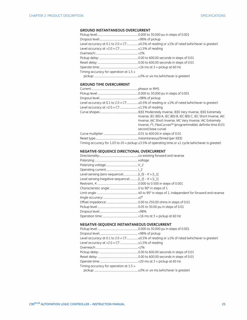
CHAPTER 2: PRODUCT DESCRIPTION SPECIFICATIONS
C90PLUS AUTOMATION LOGIC CONTROLLER – INSTRUCTION MANUAL 25
GROUND INSTANTANEOUS OVERCURRENTPickup level: ...........................................................0.000 to 30.000 pu in steps of 0.001Dropout level:........................................................<98% of pickupLevel accuracy at 0.1 to 2.0 × CT:................±0.5% of reading or ±1% of rated (whichever is greater)Level accuracy at >2.0 × CT: ..........................±1.5% of readingOverreach:..............................................................<2%Pickup delay: .........................................................0.00 to 600.00 seconds in steps of 0.01Reset delay: ...........................................................0.00 to 600.00 seconds in steps of 0.01Operate time:........................................................<16 ms at 3 × pickup at 60 HzTiming accuracy for operation at 1.5 ×
pickup: ................................................................±3% or ±4 ms (whichever is greater)
GROUND TIME OVERCURRENTCurrent: ....................................................................phasor or RMSPickup level: ...........................................................0.000 to 30.000 pu in steps of 0.001Dropout level:........................................................<98% of pickupLevel accuracy at 0.1 to 2.0 × CT:................±0.5% of reading or ±1% of rated (whichever is greater)Level accuracy at >2.0 × CT: ..........................±1.5% of readingCurve shapes: .......................................................IEEE Moderately Inverse, IEEE Very Inverse, IEEE Extremely
Inverse, IEC (BS) A, IEC (BS) B, IEC (BS) C, IEC Short Inverse, IAC Inverse, IAC Short Inverse, IAC Very Inverse, IAC Extremely Inverse, I2t , FlexCurves™ (programmable), definite time (0.01 second base curve)
Curve multiplier: ..................................................0.01 to 600.00 in steps of 0.01Reset type:..............................................................instantaneous/timed (per IEEE)Timing accuracy for 1.03 to 20 × pickup: ±3.5% of operating time or ±1 cycle (whichever is greater)
NEGATIVE-SEQUENCE DIRECTIONAL OVERCURRENTDirectionality:........................................................co-existing forward and reversePolarizing: ...............................................................voltagePolarizing voltage: ..............................................V_2Operating current: ..............................................I_2Level sensing (zero-sequence):.....................|I_0| – K × |I_1|Level sensing (negative-sequence): ...........|I_2| – K × |I_1|Restraint, K: ...........................................................0.000 to 0.500 in steps of 0.001Characteristic angle: .........................................0 to 90° in steps of 1Limit angle: ............................................................40 to 90° in steps of 1, independent for forward and reverseAngle accuracy: ...................................................±2°Offset impedance: ..............................................0.00 to 250.00 ohms in steps of 0.01Pickup level: ...........................................................0.05 to 30.00 pu in steps of 0.01Dropout level:........................................................<98%Operation time: ....................................................<16 ms at 3 × pickup at 60 Hz
NEGATIVE-SEQUENCE INSTANTANEOUS OVERCURRENTPickup level: ...........................................................0.000 to 30.000 pu in steps of 0.001Dropout level:........................................................<98% of pickupLevel accuracy at 0.1 to 2.0 × CT:................±0.5% of reading or ±1% of rated (whichever is greater)Level accuracy at >2.0 × CT: ..........................±1.5% of readingOverreach:..............................................................<2%Pickup delay: .........................................................0.00 to 600.00 seconds in steps of 0.01Reset delay: ...........................................................0.00 to 600.00 seconds in steps of 0.01Operate time:........................................................<20 ms at 3 × pickup at 60 HzTiming accuracy for operation at 1.5 ×
pickup: ................................................................±3% or ±4 ms (whichever is greater)
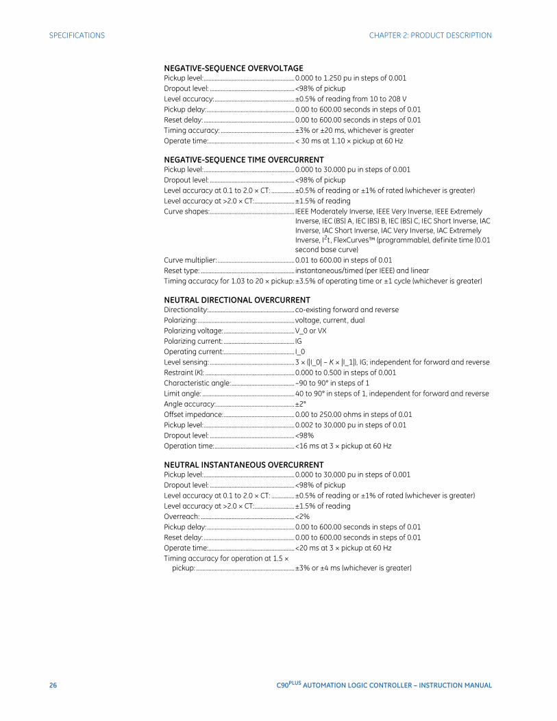
26 C90PLUS AUTOMATION LOGIC CONTROLLER – INSTRUCTION MANUAL
SPECIFICATIONS CHAPTER 2: PRODUCT DESCRIPTION
NEGATIVE-SEQUENCE OVERVOLTAGEPickup level:...........................................................0.000 to 1.250 pu in steps of 0.001Dropout level: .......................................................<98% of pickupLevel accuracy:....................................................±0.5% of reading from 10 to 208 VPickup delay:.........................................................0.00 to 600.00 seconds in steps of 0.01Reset delay: ...........................................................0.00 to 600.00 seconds in steps of 0.01Timing accuracy: ................................................±3% or ±20 ms, whichever is greaterOperate time:........................................................< 30 ms at 1.10 × pickup at 60 Hz
NEGATIVE-SEQUENCE TIME OVERCURRENTPickup level:...........................................................0.000 to 30.000 pu in steps of 0.001Dropout level: .......................................................<98% of pickupLevel accuracy at 0.1 to 2.0 × CT: ...............±0.5% of reading or ±1% of rated (whichever is greater)Level accuracy at >2.0 × CT:..........................±1.5% of readingCurve shapes:....................................................... IEEE Moderately Inverse, IEEE Very Inverse, IEEE Extremely
Inverse, IEC (BS) A, IEC (BS) B, IEC (BS) C, IEC Short Inverse, IAC Inverse, IAC Short Inverse, IAC Very Inverse, IAC Extremely Inverse, I2t , FlexCurves™ (programmable), definite time (0.01 second base curve)
Curve multiplier: ..................................................0.01 to 600.00 in steps of 0.01Reset type: ............................................................. instantaneous/timed (per IEEE) and linearTiming accuracy for 1.03 to 20 × pickup: ±3.5% of operating time or ±1 cycle (whichever is greater)
NEUTRAL DIRECTIONAL OVERCURRENTDirectionality:........................................................ co-existing forward and reversePolarizing:............................................................... voltage, current, dualPolarizing voltage:..............................................V_0 or VXPolarizing current: .............................................. IGOperating current:.............................................. I_0Level sensing: .......................................................3 × (|I_0| – K × |I_1|), IG; independent for forward and reverseRestraint (K): ..........................................................0.000 to 0.500 in steps of 0.001Characteristic angle:......................................... –90 to 90° in steps of 1Limit angle: ............................................................40 to 90° in steps of 1, independent for forward and reverseAngle accuracy:...................................................±2°Offset impedance:..............................................0.00 to 250.00 ohms in steps of 0.01Pickup level:...........................................................0.002 to 30.000 pu in steps of 0.01Dropout level: .......................................................<98%Operation time:....................................................<16 ms at 3 × pickup at 60 Hz
NEUTRAL INSTANTANEOUS OVERCURRENTPickup level:...........................................................0.000 to 30.000 pu in steps of 0.001Dropout level: .......................................................<98% of pickupLevel accuracy at 0.1 to 2.0 × CT: ...............±0.5% of reading or ±1% of rated (whichever is greater)Level accuracy at >2.0 × CT:..........................±1.5% of readingOverreach: .............................................................<2%Pickup delay:.........................................................0.00 to 600.00 seconds in steps of 0.01Reset delay: ...........................................................0.00 to 600.00 seconds in steps of 0.01Operate time:........................................................<20 ms at 3 × pickup at 60 HzTiming accuracy for operation at 1.5 ×
pickup: ................................................................±3% or ±4 ms (whichever is greater)
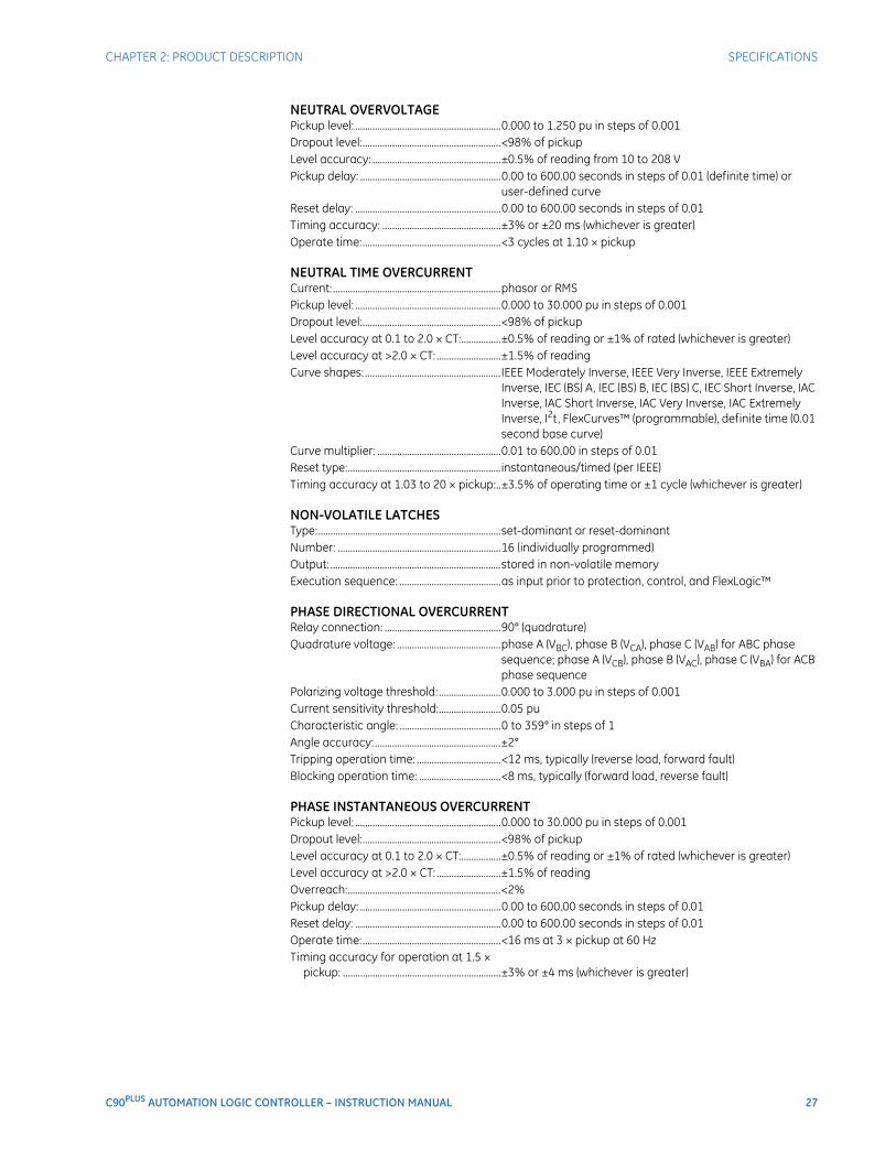
CHAPTER 2: PRODUCT DESCRIPTION SPECIFICATIONS
C90PLUS AUTOMATION LOGIC CONTROLLER – INSTRUCTION MANUAL 27
NEUTRAL OVERVOLTAGEPickup level: ...........................................................0.000 to 1.250 pu in steps of 0.001Dropout level:........................................................<98% of pickupLevel accuracy: ....................................................±0.5% of reading from 10 to 208 VPickup delay: .........................................................0.00 to 600.00 seconds in steps of 0.01 (definite time) or
user-defined curveReset delay: ...........................................................0.00 to 600.00 seconds in steps of 0.01Timing accuracy: ................................................±3% or ±20 ms (whichever is greater)Operate time:........................................................<3 cycles at 1.10 × pickup
NEUTRAL TIME OVERCURRENTCurrent: ....................................................................phasor or RMSPickup level: ...........................................................0.000 to 30.000 pu in steps of 0.001Dropout level:........................................................<98% of pickupLevel accuracy at 0.1 to 2.0 × CT:................±0.5% of reading or ±1% of rated (whichever is greater)Level accuracy at >2.0 × CT: ..........................±1.5% of readingCurve shapes: .......................................................IEEE Moderately Inverse, IEEE Very Inverse, IEEE Extremely
Inverse, IEC (BS) A, IEC (BS) B, IEC (BS) C, IEC Short Inverse, IAC Inverse, IAC Short Inverse, IAC Very Inverse, IAC Extremely Inverse, I2t , FlexCurves™ (programmable), definite time (0.01 second base curve)
Curve multiplier: ..................................................0.01 to 600.00 in steps of 0.01Reset type:..............................................................instantaneous/timed (per IEEE)Timing accuracy at 1.03 to 20 × pickup:..±3.5% of operating time or ±1 cycle (whichever is greater)
NON-VOLATILE LATCHESType:..........................................................................set-dominant or reset-dominantNumber: ..................................................................16 (individually programmed)Output: .....................................................................stored in non-volatile memoryExecution sequence: .........................................as input prior to protection, control, and FlexLogic™
PHASE DIRECTIONAL OVERCURRENTRelay connection: ...............................................90° (quadrature)Quadrature voltage: ..........................................phase A (VBC), phase B (VCA), phase C (VAB) for ABC phase
sequence; phase A (VCB), phase B (VAC), phase C (VBA) for ACB phase sequence
Polarizing voltage threshold: .........................0.000 to 3.000 pu in steps of 0.001Current sensitivity threshold:.........................0.05 puCharacteristic angle: .........................................0 to 359° in steps of 1Angle accuracy: ...................................................±2°Tripping operation time: ..................................<12 ms, typically (reverse load, forward fault)Blocking operation time: .................................<8 ms, typically (forward load, reverse fault)
PHASE INSTANTANEOUS OVERCURRENTPickup level: ...........................................................0.000 to 30.000 pu in steps of 0.001Dropout level:........................................................<98% of pickupLevel accuracy at 0.1 to 2.0 × CT:................±0.5% of reading or ±1% of rated (whichever is greater)Level accuracy at >2.0 × CT: ..........................±1.5% of readingOverreach:..............................................................<2%Pickup delay: .........................................................0.00 to 600.00 seconds in steps of 0.01Reset delay: ...........................................................0.00 to 600.00 seconds in steps of 0.01Operate time:........................................................<16 ms at 3 × pickup at 60 HzTiming accuracy for operation at 1.5 ×
pickup: ................................................................±3% or ±4 ms (whichever is greater)
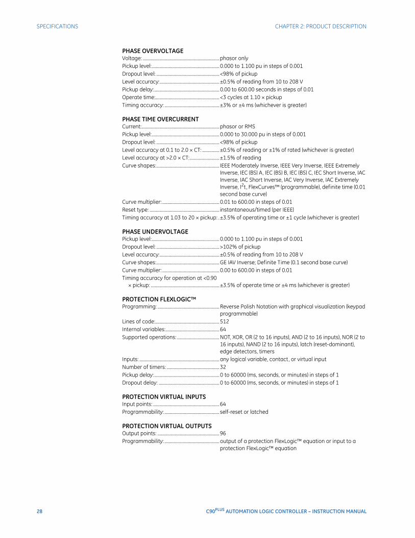
28 C90PLUS AUTOMATION LOGIC CONTROLLER – INSTRUCTION MANUAL
SPECIFICATIONS CHAPTER 2: PRODUCT DESCRIPTION
PHASE OVERVOLTAGEVoltage: ...................................................................phasor onlyPickup level:...........................................................0.000 to 1.100 pu in steps of 0.001Dropout level: .......................................................<98% of pickupLevel accuracy:....................................................±0.5% of reading from 10 to 208 VPickup delay:.........................................................0.00 to 600.00 seconds in steps of 0.01Operate time:........................................................<3 cycles at 1.10 × pickupTiming accuracy: ................................................±3% or ±4 ms (whichever is greater)
PHASE TIME OVERCURRENTCurrent:....................................................................phasor or RMSPickup level:...........................................................0.000 to 30.000 pu in steps of 0.001Dropout level: .......................................................<98% of pickupLevel accuracy at 0.1 to 2.0 × CT: ...............±0.5% of reading or ±1% of rated (whichever is greater)Level accuracy at >2.0 × CT:..........................±1.5% of readingCurve shapes:....................................................... IEEE Moderately Inverse, IEEE Very Inverse, IEEE Extremely
Inverse, IEC (BS) A, IEC (BS) B, IEC (BS) C, IEC Short Inverse, IAC Inverse, IAC Short Inverse, IAC Very Inverse, IAC Extremely Inverse, I2t , FlexCurves™ (programmable), definite time (0.01 second base curve)
Curve multiplier: ..................................................0.01 to 600.00 in steps of 0.01Reset type: ............................................................. instantaneous/timed (per IEEE)Timing accuracy at 1.03 to 20 × pickup: .±3.5% of operating time or ±1 cycle (whichever is greater)
PHASE UNDERVOLTAGEPickup level:...........................................................0.000 to 1.100 pu in steps of 0.001Dropout level: .......................................................>102% of pickupLevel accuracy:....................................................±0.5% of reading from 10 to 208 VCurve shapes:.......................................................GE IAV Inverse; Definite Time (0.1 second base curve)Curve multiplier: ..................................................0.00 to 600.00 in steps of 0.01Timing accuracy for operation at <0.90
× pickup: ............................................................±3.5% of operate time or ±4 ms (whichever is greater)
PROTECTION FLEXLOGIC™Programming: ......................................................Reverse Polish Notation with graphical visualization (keypad
programmable)Lines of code:........................................................512Internal variables:...............................................64Supported operations: .....................................NOT, XOR, OR (2 to 16 inputs), AND (2 to 16 inputs), NOR (2 to
16 inputs), NAND (2 to 16 inputs), latch (reset-dominant), edge detectors, timers
Inputs: ......................................................................any logical variable, contact, or virtual inputNumber of timers: ..............................................32Pickup delay:.........................................................0 to 60000 (ms, seconds, or minutes) in steps of 1Dropout delay: .....................................................0 to 60000 (ms, seconds, or minutes) in steps of 1
PROTECTION VIRTUAL INPUTSInput points: ..........................................................64Programmability: ................................................ self-reset or latched
PROTECTION VIRTUAL OUTPUTSOutput points: ......................................................96Programmability: ................................................output of a protection FlexLogic™ equation or input to a
protection FlexLogic™ equation
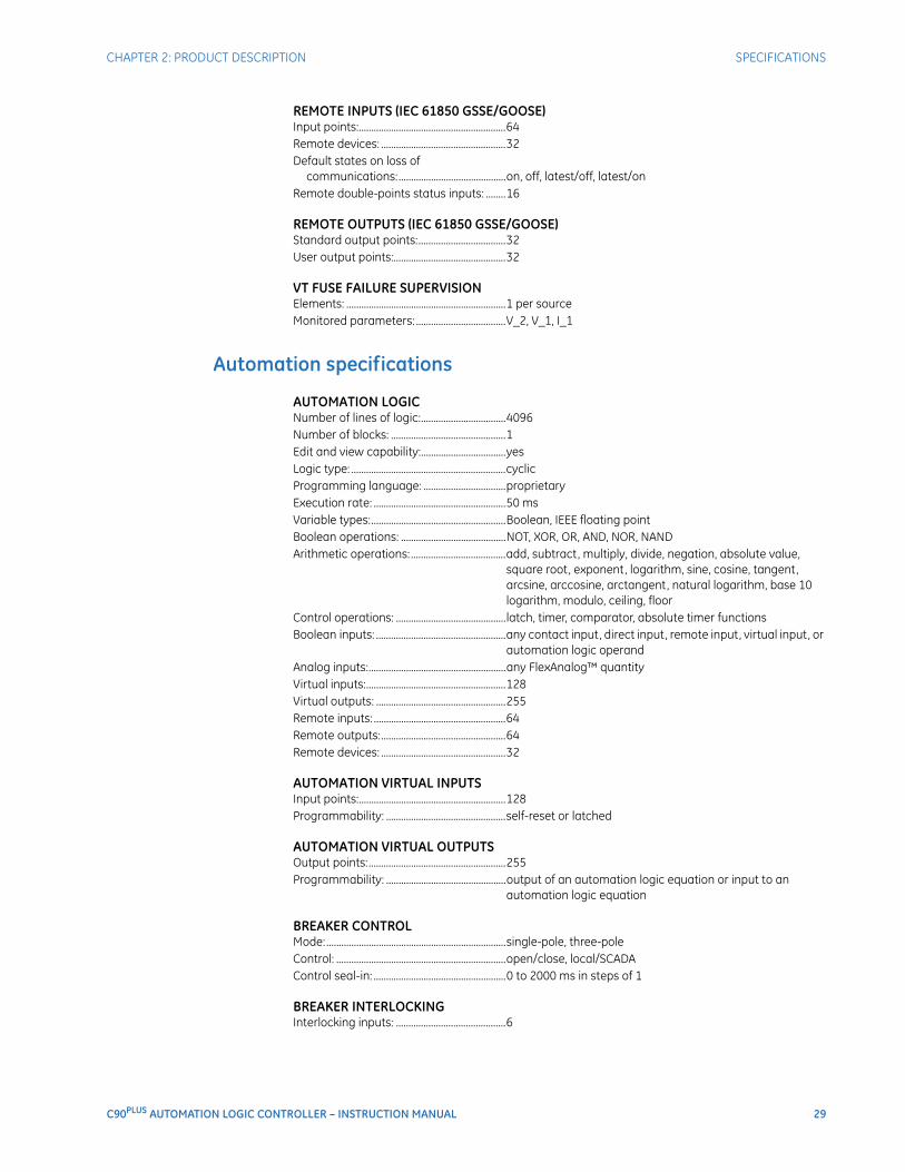
CHAPTER 2: PRODUCT DESCRIPTION SPECIFICATIONS
C90PLUS AUTOMATION LOGIC CONTROLLER – INSTRUCTION MANUAL 29
REMOTE INPUTS (IEC 61850 GSSE/GOOSE)Input points:...........................................................64Remote devices: ..................................................32Default states on loss of
communications:...........................................on, off, latest/off, latest/onRemote double-points status inputs: ........16
REMOTE OUTPUTS (IEC 61850 GSSE/GOOSE)Standard output points:...................................32User output points:.............................................32
VT FUSE FAILURE SUPERVISIONElements: ................................................................1 per sourceMonitored parameters: ....................................V_2, V_1, I_1
Automation specifications
AUTOMATION LOGICNumber of lines of logic:..................................4096Number of blocks: ..............................................1Edit and view capability:..................................yesLogic type: ..............................................................cyclicProgramming language: .................................proprietaryExecution rate: .....................................................50 msVariable types:......................................................Boolean, IEEE floating pointBoolean operations: ..........................................NOT, XOR, OR, AND, NOR, NANDArithmetic operations: ......................................add, subtract, multiply, divide, negation, absolute value,
square root, exponent, logarithm, sine, cosine, tangent, arcsine, arccosine, arctangent, natural logarithm, base 10 logarithm, modulo, ceiling, floor
Control operations: ............................................latch, timer, comparator, absolute timer functionsBoolean inputs: ....................................................any contact input, direct input, remote input, virtual input, or
automation logic operandAnalog inputs:.......................................................any FlexAnalog™ quantityVirtual inputs:........................................................128Virtual outputs: ....................................................255Remote inputs: .....................................................64Remote outputs:..................................................64Remote devices: ..................................................32
AUTOMATION VIRTUAL INPUTSInput points:...........................................................128Programmability: ................................................self-reset or latched
AUTOMATION VIRTUAL OUTPUTSOutput points:.......................................................255Programmability: ................................................output of an automation logic equation or input to an
automation logic equation
BREAKER CONTROLMode:........................................................................single-pole, three-poleControl: ....................................................................open/close, local/SCADAControl seal-in: .....................................................0 to 2000 ms in steps of 1
BREAKER INTERLOCKINGInterlocking inputs: ............................................6
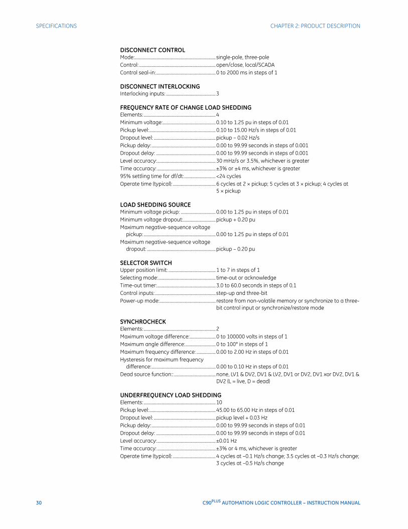
30 C90PLUS AUTOMATION LOGIC CONTROLLER – INSTRUCTION MANUAL
SPECIFICATIONS CHAPTER 2: PRODUCT DESCRIPTION
DISCONNECT CONTROLMode:........................................................................ single-pole, three-poleControl: ....................................................................open/close, local/SCADAControl seal-in:.....................................................0 to 2000 ms in steps of 1
DISCONNECT INTERLOCKINGInterlocking inputs: ............................................3
FREQUENCY RATE OF CHANGE LOAD SHEDDINGElements: ................................................................4Minimum voltage:...............................................0.10 to 1.25 pu in steps of 0.01Pickup level:...........................................................0.10 to 15.00 Hz/s in steps of 0.01Dropout level: .......................................................pickup – 0.02 Hz/sPickup delay:.........................................................0.00 to 99.99 seconds in steps of 0.001Dropout delay: .....................................................0.00 to 99.99 seconds in steps of 0.001Level accuracy:....................................................30 mHz/s or 3.5%, whichever is greaterTime accuracy: ....................................................±3% or ±4 ms, whichever is greater95% settling time for df/dt:............................<24 cyclesOperate time (typical): ......................................6 cycles at 2 × pickup; 5 cycles at 3 × pickup; 4 cycles at
5 × pickup
LOAD SHEDDING SOURCEMinimum voltage pickup: ...............................0.00 to 1.25 pu in steps of 0.01Minimum voltage dropout:.............................pickup + 0.20 puMaximum negative-sequence voltage
pickup: ................................................................0.00 to 1.25 pu in steps of 0.01Maximum negative-sequence voltage
dropout: .............................................................pickup – 0.20 pu
SELECTOR SWITCHUpper position limit: ..........................................1 to 7 in steps of 1Selecting mode:................................................... time-out or acknowledgeTime-out timer:....................................................3.0 to 60.0 seconds in steps of 0.1Control inputs:...................................................... step-up and three-bitPower-up mode:.................................................. restore from non-volatile memory or synchronize to a three-
bit control input or synchronize/restore mode
SYNCHROCHECKElements: ................................................................2Maximum voltage difference:.......................0 to 100000 volts in steps of 1Maximum angle difference:...........................0 to 100° in steps of 1Maximum frequency difference: .................0.00 to 2.00 Hz in steps of 0.01Hysteresis for maximum frequency
difference:.........................................................0.00 to 0.10 Hz in steps of 0.01Dead source function:: .....................................none, LV1 & DV2, DV1 & LV2, DV1 or DV2, DV1 xor DV2, DV1 &
DV2 (L = live, D = dead)
UNDERFREQUENCY LOAD SHEDDINGElements: ................................................................10Pickup level:...........................................................45.00 to 65.00 Hz in steps of 0.01Dropout level: .......................................................pickup level + 0.03 HzPickup delay:.........................................................0.00 to 99.99 seconds in steps of 0.01Dropout delay: .....................................................0.00 to 99.99 seconds in steps of 0.01Level accuracy:....................................................±0.01 HzTime accuracy: ....................................................±3% or 4 ms, whichever is greaterOperate time (typical): ......................................4 cycles at –0.1 Hz/s change; 3.5 cycles at –0.3 Hz/s change;
3 cycles at –0.5 Hz/s change
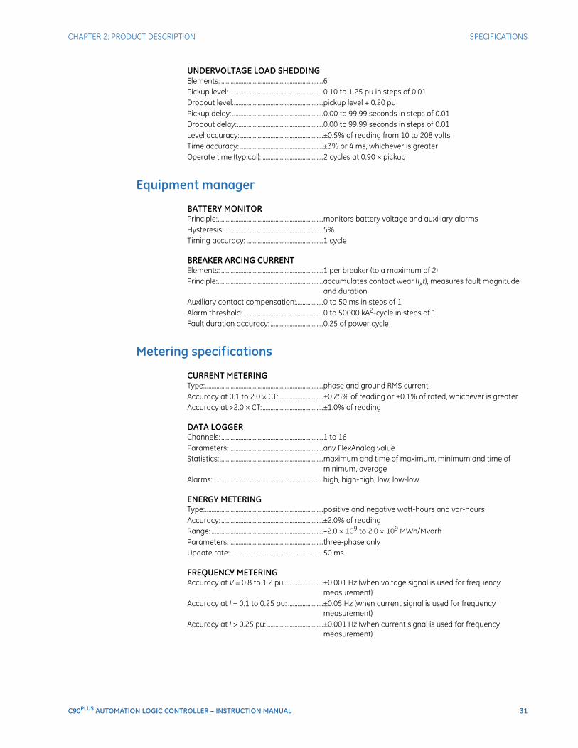
CHAPTER 2: PRODUCT DESCRIPTION SPECIFICATIONS
C90PLUS AUTOMATION LOGIC CONTROLLER – INSTRUCTION MANUAL 31
UNDERVOLTAGE LOAD SHEDDINGElements: ................................................................6Pickup level: ...........................................................0.10 to 1.25 pu in steps of 0.01Dropout level:........................................................pickup level + 0.20 puPickup delay: .........................................................0.00 to 99.99 seconds in steps of 0.01Dropout delay:......................................................0.00 to 99.99 seconds in steps of 0.01Level accuracy: ....................................................±0.5% of reading from 10 to 208 voltsTime accuracy: ....................................................±3% or 4 ms, whichever is greaterOperate time (typical): ......................................2 cycles at 0.90 × pickup
Equipment manager
BATTERY MONITORPrinciple:..................................................................monitors battery voltage and auxiliary alarmsHysteresis: ..............................................................5%Timing accuracy: ................................................1 cycle
BREAKER ARCING CURRENTElements: ................................................................1 per breaker (to a maximum of 2)Principle:..................................................................accumulates contact wear (Ixt), measures fault magnitude
and durationAuxiliary contact compensation:.................0 to 50 ms in steps of 1Alarm threshold: ..................................................0 to 50000 kA2-cycle in steps of 1Fault duration accuracy: .................................0.25 of power cycle
Metering specifications
CURRENT METERINGType:..........................................................................phase and ground RMS currentAccuracy at 0.1 to 2.0 × CT:............................±0.25% of reading or ±0.1% of rated, whichever is greaterAccuracy at >2.0 × CT: ......................................±1.0% of reading
DATA LOGGERChannels: ................................................................1 to 16Parameters: ...........................................................any FlexAnalog valueStatistics:.................................................................maximum and time of maximum, minimum and time of
minimum, averageAlarms: .....................................................................high, high-high, low, low-low
ENERGY METERINGType:..........................................................................positive and negative watt-hours and var-hoursAccuracy: ................................................................±2.0% of readingRange: ......................................................................–2.0 × 10⁹ to 2.0 × 10⁹ MWh/MvarhParameters: ...........................................................three-phase onlyUpdate rate: ..........................................................50 ms
FREQUENCY METERINGAccuracy at V = 0.8 to 1.2 pu:........................±0.001 Hz (when voltage signal is used for frequency
measurement)Accuracy at I = 0.1 to 0.25 pu: ......................±0.05 Hz (when current signal is used for frequency
measurement)Accuracy at I > 0.25 pu: ...................................±0.001 Hz (when current signal is used for frequency
measurement)
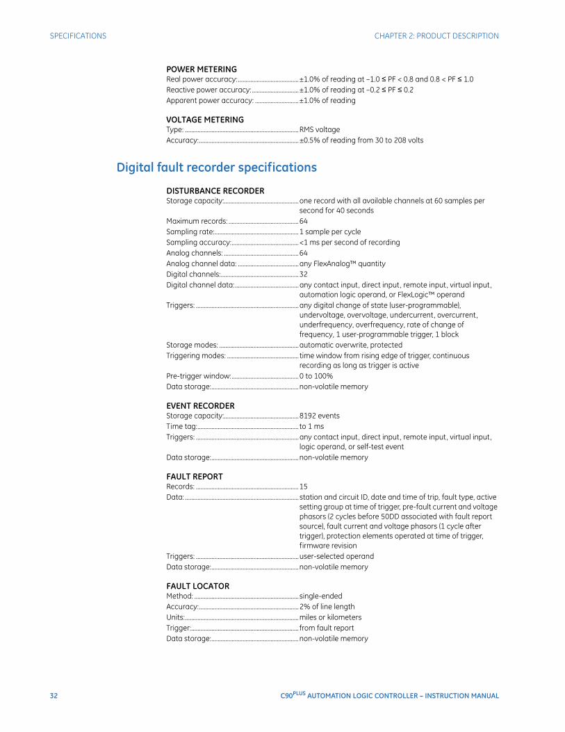
32 C90PLUS AUTOMATION LOGIC CONTROLLER – INSTRUCTION MANUAL
SPECIFICATIONS CHAPTER 2: PRODUCT DESCRIPTION
POWER METERINGReal power accuracy:.......................................±1.0% of reading at –1.0 ≤ PF < 0.8 and 0.8 < PF ≤ 1.0Reactive power accuracy: ..............................±1.0% of reading at –0.2 ≤ PF ≤ 0.2Apparent power accuracy: ............................±1.0% of reading
VOLTAGE METERINGType: .........................................................................RMS voltageAccuracy:................................................................±0.5% of reading from 30 to 208 volts
Digital fault recorder specifications
DISTURBANCE RECORDERStorage capacity:................................................one record with all available channels at 60 samples per
second for 40 secondsMaximum records: .............................................64Sampling rate:......................................................1 sample per cycleSampling accuracy:...........................................<1 ms per second of recordingAnalog channels: ................................................64Analog channel data: .......................................any FlexAnalog™ quantityDigital channels:..................................................32Digital channel data:.........................................any contact input, direct input, remote input, virtual input,
automation logic operand, or FlexLogic™ operandTriggers: ..................................................................any digital change of state (user-programmable),
undervoltage, overvoltage, undercurrent, overcurrent, underfrequency, overfrequency, rate of change of frequency, 1 user-programmable trigger, 1 block
Storage modes: ...................................................automatic overwrite, protectedTriggering modes: .............................................. time window from rising edge of trigger, continuous
recording as long as trigger is activePre-trigger window:...........................................0 to 100%Data storage:........................................................non-volatile memory
EVENT RECORDERStorage capacity:................................................8192 eventsTime tag:................................................................. to 1 msTriggers: ..................................................................any contact input, direct input, remote input, virtual input,
logic operand, or self-test eventData storage:........................................................non-volatile memory
FAULT REPORTRecords: ..................................................................15Data: ......................................................................... station and circuit ID, date and time of trip, fault type, active
setting group at time of trigger, pre-fault current and voltage phasors (2 cycles before 50DD associated with fault report source), fault current and voltage phasors (1 cycle after trigger), protection elements operated at time of trigger, firmware revision
Triggers: ..................................................................user-selected operandData storage:........................................................non-volatile memory
FAULT LOCATORMethod: ................................................................... single-endedAccuracy:................................................................2% of line lengthUnits:.........................................................................miles or kilometersTrigger:..................................................................... from fault reportData storage:........................................................non-volatile memory
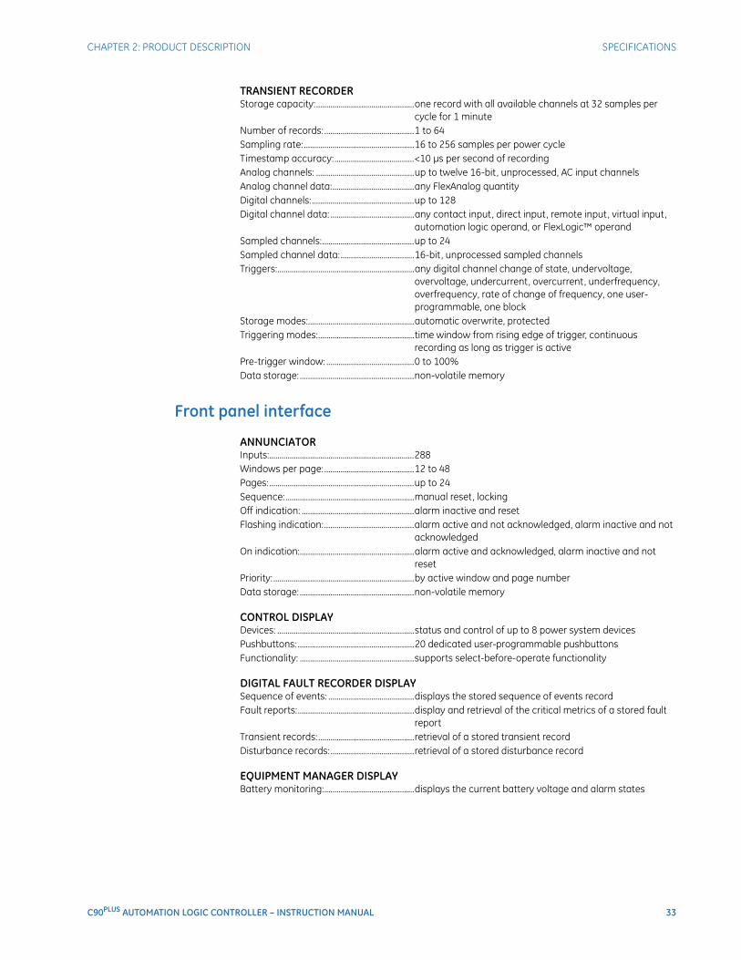
CHAPTER 2: PRODUCT DESCRIPTION SPECIFICATIONS
C90PLUS AUTOMATION LOGIC CONTROLLER – INSTRUCTION MANUAL 33
TRANSIENT RECORDERStorage capacity:................................................one record with all available channels at 32 samples per
cycle for 1 minuteNumber of records: ............................................1 to 64Sampling rate: ......................................................16 to 256 samples per power cycleTimestamp accuracy:.......................................<10 μs per second of recordingAnalog channels: ................................................up to twelve 16-bit , unprocessed, AC input channelsAnalog channel data:........................................any FlexAnalog quantityDigital channels: ..................................................up to 128Digital channel data: .........................................any contact input, direct input, remote input, virtual input,
automation logic operand, or FlexLogic™ operandSampled channels:.............................................up to 24Sampled channel data:....................................16-bit , unprocessed sampled channelsTriggers:...................................................................any digital channel change of state, undervoltage,
overvoltage, undercurrent, overcurrent, underfrequency, overfrequency, rate of change of frequency, one user-programmable, one block
Storage modes:....................................................automatic overwrite, protectedTriggering modes:...............................................time window from rising edge of trigger, continuous
recording as long as trigger is activePre-trigger window: ...........................................0 to 100%Data storage: ........................................................non-volatile memory
Front panel interface
ANNUNCIATORInputs:.......................................................................288Windows per page:............................................12 to 48Pages:.......................................................................up to 24Sequence:...............................................................manual reset, lockingOff indication: .......................................................alarm inactive and resetFlashing indication:............................................alarm active and not acknowledged, alarm inactive and not
acknowledgedOn indication:........................................................alarm active and acknowledged, alarm inactive and not
resetPriority: .....................................................................by active window and page numberData storage: ........................................................non-volatile memory
CONTROL DISPLAYDevices: ...................................................................status and control of up to 8 power system devicesPushbuttons: .........................................................20 dedicated user-programmable pushbuttonsFunctionality: ........................................................supports select-before-operate functionality
DIGITAL FAULT RECORDER DISPLAYSequence of events: ..........................................displays the stored sequence of events recordFault reports:.........................................................display and retrieval of the critical metrics of a stored fault
reportTransient records:...............................................retrieval of a stored transient recordDisturbance records:.........................................retrieval of a stored disturbance record
EQUIPMENT MANAGER DISPLAYBattery monitoring:............................................displays the current battery voltage and alarm states
34 C90PLUS AUTOMATION LOGIC CONTROLLER – INSTRUCTION MANUAL
SPECIFICATIONS CHAPTER 2: PRODUCT DESCRIPTION
METERING DISPLAYSummary:...............................................................displays present values of voltage, current, real power,
reactive power, power factor, and frequency on a per-phase and total basis
Phasors: ..................................................................digital and graphical display of present voltage and current magnitudes and angles
Sequence components:...................................displays present magnitudes and angles of current and voltage sequence components
Energy:..................................................................... four-quadrant display of accumulated energyDemand: .................................................................present and peak demand values for current and real,
reactive, and apparent power
MAINTENANCE DISPLAYInput and output status: .................................displays the current status of all contact inputs and outputs
Hardware specifications
AC CURRENTCT rated primary:................................................1 to 50000 ACT rated secondary: ..........................................1 A or 5 ANominal frequency: ...........................................50 or 60 HzRelay burden:........................................................<0.2 VA secondaryConversion range: ..............................................0.02 to 46 × CT rating RMS symmetricalCurrent withstand: .............................................20 ms at 250 × rated, 1 second at 100 × rated, continuous at
3 × rated
AC VOLTAGEVT rated secondary: ..........................................50.0 to 240.0 VVT ratio: ...................................................................1.00 to 24000.0Nominal frequency: ...........................................50 or 60 HzRelay burden:........................................................<0.25 VA at 120 VConversion range: ..............................................1 to 275 VVoltage withstand: ............................................. continuous at 260 V to neutral, 1 minute per hour at 420 V
neutral
CONTACT INPUTSInput rating:...........................................................300 V DC maximumSelectable thresholds: ......................................24 to 250 VMaximum current:..............................................10 mA during turn on, 0.5 mA steady-stateRecognition time:................................................<1 msDebounce timer: .................................................1.50 to 16.00 ms in steps of 0.25
CONTACT OUTPUTS: CRITICAL FAILURE RELAYMake and carry for 0.2 s: ................................10 AContinuous carry: ...............................................6 ABreak at L/R of 40 ms: ......................................0.250 A at 125 V DC; 0.125 A at 250 V DCOperate time:........................................................<8 msContact material:................................................ silver alloy
CONTACT OUTPUTS: FORM-A RELAYMake and carry for 0.2 s: ................................30 A as per ANSI C37.90Continuous carry: ...............................................6 ABreak at L/R of 40 ms: ......................................0.250 A at 125 V DC; 0.125 A at 250 V DCOperate time:........................................................<4 msContact material:................................................ silver alloy
CHAPTER 2: PRODUCT DESCRIPTION SPECIFICATIONS
C90PLUS AUTOMATION LOGIC CONTROLLER – INSTRUCTION MANUAL 35
CONTACT OUTPUTS: SOLID-STATE RELAYMake and carry for 0.2 s:.................................30 A as per ANSI C37.90Continuous carry: ...............................................6 ABreak at L/R of 40 ms:.......................................10 A at 250 V DCOperate time:........................................................<100 μsContact material: ................................................silver alloy
CONTROL POWER EXTERNAL OUTPUTCapacity: .................................................................100 mA DC at 48 V DCIsolation:..................................................................2 kV
CRITICAL FAILURE RELAYMake and carry for 0.2 s:.................................30 A as per ANSI C37.90Carry continuous: ...............................................6 ABreak at L/R of 40 ms:.......................................0.250 A DC at 125 V DC; 0.125 A DC at 250 V DC; 0.10 A DC
maximum at 125 VOperate time:........................................................<8 msContact material: ................................................silver alloy
ETHERNET PORTSStandard: ................................................................1 port supporting Modbus TCPOptional:..................................................................2 ports supporting DNP 3.0, IEC 60870-5-104, or IEC 61850
located on communications module100Base-FX media type: .................................1300 nm, multi-mode, half/full-duplex, fiber optic with ST
connector10/100Base-TX media type: ..........................RJ45 connectorPower budget: ......................................................10 dBMaximum optical input power: ....................–14 dBmReceiver sensitivity:............................................–30 dBmTypical distance:..................................................2.0 kmSNTP clock synchronization:..........................<10 ms typical
FORM-A RELAYMake and carry for 0.2 s:.................................30 A per ANSI C37.90Carry continuous: ...............................................6 ABreak at L/R of 40 ms:.......................................0.250 A DC at 125 V DC; 0.125 A DC at 250 V DCOperate time:........................................................<4 msContact material: ................................................silver alloy
IRIG-B INPUTAmplitude modulation:.....................................1 to 10 V pk-pkDC shift: ...................................................................TTLInput impedance:................................................50 kΩIsolation:..................................................................2 kV
POWER SUPPLYNominal DC voltage:..........................................125 to 250 VMinimum DC voltage:........................................80 VMaximum DC voltage: ......................................300 VNominal AC voltage: ..........................................100 to 240 V at 50/60 HzMinimum AC voltage: ........................................80 V at 48 to 62 HzMaximum AC voltage:.......................................275 V at 48 to 62 HzVoltage withstand: .............................................2 × highest nominal voltage for 10 msVoltage loss hold-up:.........................................200 ms duration at nominalPower consumption: .........................................30 VA typical, 65 VA maximum
36 C90PLUS AUTOMATION LOGIC CONTROLLER – INSTRUCTION MANUAL
SPECIFICATIONS CHAPTER 2: PRODUCT DESCRIPTION
RS485 PORTBaud rates: ............................................................300, 600, 1200, 2400, 4800, 9600, 19200, 38400, 57600,
115200Protocol: ..................................................................Modbus RTU and DNP 3.0Distance: .................................................................1200 mIsolation: .................................................................2 kV
SOLID-STATE RELAYMake and carry for 0.2 s: ................................30 A as per ANSI C37.90Carry continuous: ...............................................6 ABreak at L/R of 40 ms: ......................................10.0 A DC at 250 V DCOperate time:........................................................< 100 μs
USB PORTStandard: ................................................................ type B USB connector for EnerVista software
Communications specifications
MODBUS USER MAPNumber: ..................................................................up to 256 Modbus addressesProgrammability: ................................................any setting or actual value in decimal
REMOTE INPUTS (IEC 61850 GSSE/GOOSE)Input points: ..........................................................64Remote devices:..................................................32Default states on loss of
communications:...........................................On, Off, Latest/Off, Latest/OnRemote double-point status inputs: ..........16
REMOTE OUTPUTS (IEC 61850 GSSE/GOOSE)Standard output points: ..................................32User output points: ............................................32
Test specifications
PRODUCTION TESTSThermal: ..................................................................products go through a 12 hour burn-in process at 60°C
TYPE TESTSVibration: ................................................................ IEC 60255-21-1, 1G (class Bm)Shock / bump: ...................................................... IEC 60255-21-2, 10G (class Bm)Conducted immunity: ....................................... IEC 61000-4-6 / IEC60255-22-6, class 3 (10 V RMS)Surge: ....................................................................... IEC 61000-4-5 or IEC 60225-22-5, 1.2/50 test up to level 4
(4 kV)Burst disturbance (1 MHz oscillatory): ...... IEC60255-22-1 up to 2.5 kV at 1 MHz dampedFast transients: ....................................................ANSI/IEEE C37.90.1, EC61000-4-4 class 4, (2 kV, 5 kHz / 4 kV,
2.5 kHz, 2 kV on data control ports and inputs/outputs), IEC 60255-22-4
Radiated immunity: ........................................... IEC 61000-4-3 / IEC 60255-22-3 class 3 (10 V/m) or IEEE C37.90.2 radiated RFI (35 V/m)
Power frequency disturbance: ..................... IEC 61000-4-8 (30 A/m) class 4Radiated/conducted emissions:.................. IEC 60255-25 / CISPR 11/22 class AInsulation resistance:........................................ IEC 60255-5Dielectric strength:............................................. IEC 60255-5, ANSI/IEEE C37.90Electrostatic discharge: ................................... EN 61000-4-2, IEC60255-22-2 8 kV C, 15 kV A, L4Voltage dips/interruptions/variations: ..... IEC 61000-4-11 (30% 1 cycle), IEC 60255-11AC ripple:................................................................. IEC 61000-4-17 (standard)

CHAPTER 2: PRODUCT DESCRIPTION SPECIFICATIONS
C90PLUS AUTOMATION LOGIC CONTROLLER – INSTRUCTION MANUAL 37
Environmental specifications
OPERATING TEMPERATURECold: ..........................................................................IEC 60028-2-1, 16 hours at –40°CDry heat:..................................................................IEC 60028-2-2, 16 hours at 85°C
OTHER ENVIRONMENTAL SPECIFICATIONSAltitude:....................................................................up to 2000 mInstallation category: ........................................IIIP rating: ..................................................................IP30
Approvals and certification
APPROVALSUL508 17th edition and C22.2 No.14-05: UL listed for the USA and Canada
CERTIFICATIONCE LVD 2006/95/EC: ...........................................EN/IEC 61010-1:2001 / EN60255-5:2000CE EMC 89/336/EEC:..........................................EN 60255-26:2004-08

38 C90PLUS AUTOMATION LOGIC CONTROLLER – INSTRUCTION MANUAL
SPECIFICATIONS CHAPTER 2: PRODUCT DESCRIPTION
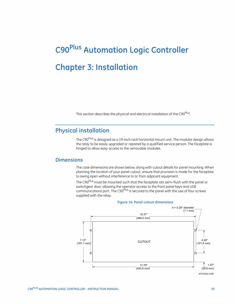
C90PLUS AUTOMATION LOGIC CONTROLLER – INSTRUCTION MANUAL 39
C90Plus Automation Logic Controller
Chapter 3: Installation
Installation
This section describes the physical and electrical installation of the C90Plus.
Physical installationThe C90Plus is designed as a 19-inch rack horizontal mount unit. The modular design allows the relay to be easily upgraded or repaired by a qualified service person. The faceplate is hinged to allow easy access to the removable modules.
DimensionsThe case dimensions are shown below, along with cutout details for panel mounting. When planning the location of your panel cutout, ensure that provision is made for the faceplate to swing open without interference to or from adjacent equipment.
The C90Plus must be mounted such that the faceplate sits semi-flush with the panel or switchgear door, allowing the operator access to the front panel keys and USB communications port. The C90Plus is secured to the panel with the use of four screws supplied with the relay.
Figure 14: Panel cutout dimensions
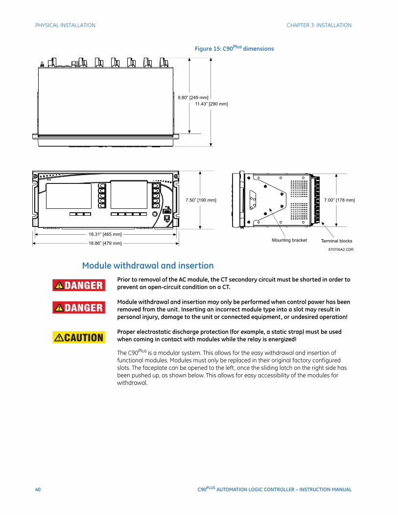
40 C90PLUS AUTOMATION LOGIC CONTROLLER – INSTRUCTION MANUAL
PHYSICAL INSTALLATION CHAPTER 3: INSTALLATION
Figure 15: C90Plus dimensions
Module withdrawal and insertionDANGER: Prior to removal of the AC module, the CT secondary circuit must be shorted in order to
prevent an open-circuit condition on a CT.
DANGER: Module withdrawal and insertion may only be performed when control power has been removed from the unit. Inserting an incorrect module type into a slot may result in personal injury, damage to the unit or connected equipment, or undesired operation!
CAUTION: Proper electrostatic discharge protection (for example, a static strap) must be used when coming in contact with modules while the relay is energized!
The C90Plus is a modular system. This allows for the easy withdrawal and insertion of functional modules. Modules must only be replaced in their original factory configured slots. The faceplate can be opened to the left, once the sliding latch on the right side has been pushed up, as shown below. This allows for easy accessibility of the modules for withdrawal.
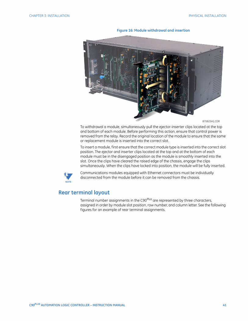
CHAPTER 3: INSTALLATION PHYSICAL INSTALLATION
C90PLUS AUTOMATION LOGIC CONTROLLER – INSTRUCTION MANUAL 41
Figure 16: Module withdrawal and insertion
To withdrawal a module, simultaneously pull the ejector-inserter clips located at the top and bottom of each module. Before performing this action, ensure that control power is removed from the relay. Record the original location of the module to ensure that the same or replacement module is inserted into the correct slot.
To insert a module, first ensure that the correct module type is inserted into the correct slot position. The ejector and inserter clips located at the top and at the bottom of each module must be in the disengaged position as the module is smoothly inserted into the slot. Once the clips have cleared the raised edge of the chassis, engage the clips simultaneously. When the clips have locked into position, the module will be fully inserted.
NOTE
NOTE: Communications modules equipped with Ethernet connectors must be individually disconnected from the module before it can be removed from the chassis.
Rear terminal layoutTerminal number assignments in the C90Plus are represented by three characters, assigned in order by module slot position, row number, and column letter. See the following figures for an example of rear terminal assignments.
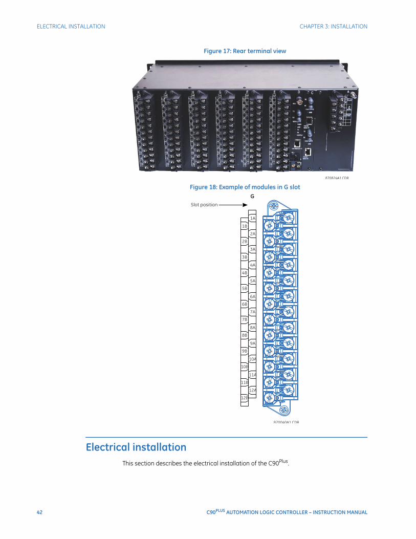
42 C90PLUS AUTOMATION LOGIC CONTROLLER – INSTRUCTION MANUAL
ELECTRICAL INSTALLATION CHAPTER 3: INSTALLATION
Figure 17: Rear terminal view
Figure 18: Example of modules in G slot
Electrical installationThis section describes the electrical installation of the C90Plus.
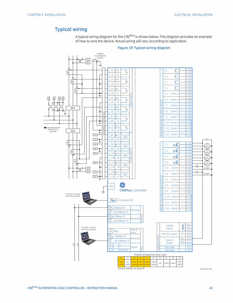
CHAPTER 3: INSTALLATION ELECTRICAL INSTALLATION
C90PLUS AUTOMATION LOGIC CONTROLLER – INSTRUCTION MANUAL 43
Typical wiringA typical wiring diagram for the C90Plus is shown below. This diagram provides an example of how to wire the device. Actual wiring will vary according to application.
Figure 19: Typical wiring diagram
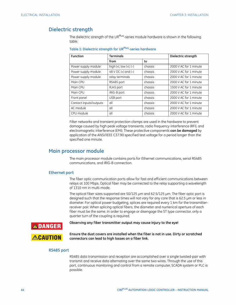
44 C90PLUS AUTOMATION LOGIC CONTROLLER – INSTRUCTION MANUAL
ELECTRICAL INSTALLATION CHAPTER 3: INSTALLATION
Dielectric strengthThe dielectric strength of the URPlus-series module hardware is shown in the following table.
Table 1: Dielectric strength for URPlus-series hardware
Filter networks and transient protection clamps are used in the hardware to prevent damage caused by high peak voltage transients, radio frequency interference (RFI), and electromagnetic interference (EMI). These protective components can be damaged by application of the ANSI/IEEE C37.90 specified test voltage for a period longer than the specified one minute.
Main processor moduleThe main processor module contains ports for Ethernet communications, serial RS485 communications, and IRIG-B connection.
Ethernet portThe fiber optic communication ports allow for fast and efficient communications between relays at 100 Mbps. Optical fiber may be connected to the relay supporting a wavelength of 1310 nm in multi-mode.
The optical fiber sizes supported are 50/125 µm and 62.5/125 µm. The fiber optic port is designed such that the response times will not vary for any core that is 62.5 µm or less in diameter. For optical power budgeting, splices are required every 1 km for the transmitter-receiver pair. When splicing optical fibers, the diameter and numerical aperture of each fiber must be the same. In order to engage or disengage the ST type connector, only a quarter turn of the coupling is required.
DANGER: Observing any fiber transmitter output may cause injury to the eye!
CAUTION: Ensure the dust covers are installed when the fiber is not in use. Dirty or scratched connectors can lead to high losses on a fiber link.
RS485 portRS485 data transmission and reception are accomplished over a single twisted-pair with transmit and receive data alternating over the same two wires. Through the use of this port, continuous monitoring and control from a remote computer, SCADA system or PLC is possible.
Function Terminals Dielectric strength
from to
Power supply module high (+), low (+), (–) chassis 2000 V AC for 1 minute
Power supply module 48 V DC (+) and (–) chassis 2000 V AC for 1 minute
Power supply module relay terminals chassis 2000 V AC for 1 minute
Main CPU RS485 port chassis 2000 V AC for 1 minute
Main CPU RJ45 port chassis 1500 V AC for 1 minute
Main CPU IRIG-B port chassis 2000 V AC for 1 minute
Front panel USB port chassis 2000 V AC for 1 minute
Contact inputs/outputs all chassis 2000 V AC for 1 minute
AC module all chassis 2000 V AC for 1 minute
CPU module all chassis 2000 V AC for 1 minute
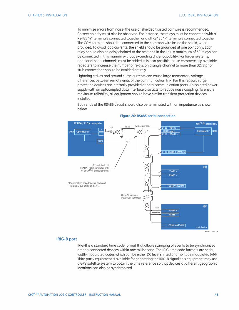
CHAPTER 3: INSTALLATION ELECTRICAL INSTALLATION
C90PLUS AUTOMATION LOGIC CONTROLLER – INSTRUCTION MANUAL 45
To minimize errors from noise, the use of shielded twisted pair wire is recommended. Correct polarity must also be observed. For instance, the relays must be connected with all RS485 “+” terminals connected together, and all RS485 “–” terminals connected together. The COM terminal should be connected to the common wire inside the shield, when provided. To avoid loop currents, the shield should be grounded at one point only. Each relay should also be daisy chained to the next one in the link. A maximum of 32 relays can be connected in this manner without exceeding driver capability. For larger systems, additional serial channels must be added. It is also possible to use commercially available repeaters to increase the number of relays on a single channel to more than 32. Star or stub connections should be avoided entirely.
Lightning strikes and ground surge currents can cause large momentary voltage differences between remote ends of the communication link. For this reason, surge protection devices are internally provided at both communication ports. An isolated power supply with an optocoupled data interface also acts to reduce noise coupling. To ensure maximum reliability, all equipment should have similar transient protection devices installed.
Both ends of the RS485 circuit should also be terminated with an impedance as shown below.
Figure 20: RS485 serial connection
IRIG-B portIRIG-B is a standard time code format that allows stamping of events to be synchronized among connected devices within one millisecond. The IRIG time code formats are serial, width-modulated codes which can be either DC level shifted or amplitude modulated (AM). Third party equipment is available for generating the IRIG-B signal; this equipment may use a GPS satellite system to obtain the time reference so that devices at different geographic locations can also be synchronized.
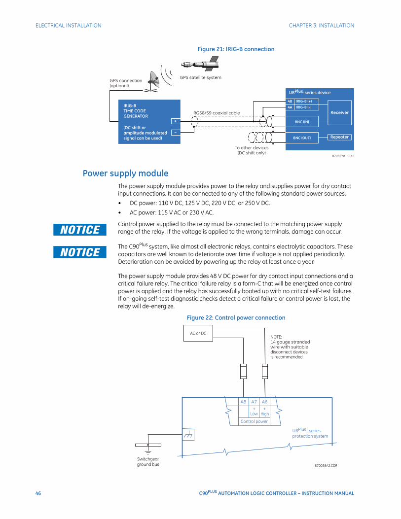
46 C90PLUS AUTOMATION LOGIC CONTROLLER – INSTRUCTION MANUAL
ELECTRICAL INSTALLATION CHAPTER 3: INSTALLATION
Figure 21: IRIG-B connection
Power supply moduleThe power supply module provides power to the relay and supplies power for dry contact input connections. It can be connected to any of the following standard power sources.
• DC power: 110 V DC, 125 V DC, 220 V DC, or 250 V DC.
• AC power: 115 V AC or 230 V AC.FASTPATH: Control power supplied to the relay must be connected to the matching power supply
range of the relay. If the voltage is applied to the wrong terminals, damage can occur.
FASTPATH: The C90Plus system, like almost all electronic relays, contains electrolytic capacitors. These capacitors are well known to deteriorate over time if voltage is not applied periodically. Deterioration can be avoided by powering up the relay at least once a year.
The power supply module provides 48 V DC power for dry contact input connections and a critical failure relay. The critical failure relay is a form-C that will be energized once control power is applied and the relay has successfully booted up with no critical self-test failures. If on-going self-test diagnostic checks detect a critical failure or control power is lost, the relay will de-energize.
Figure 22: Control power connection

CHAPTER 3: INSTALLATION ELECTRICAL INSTALLATION
C90PLUS AUTOMATION LOGIC CONTROLLER – INSTRUCTION MANUAL 47
AC modulesAn AC module has voltage inputs on channels 8 through 12 inclusive. Channel 10 is intended for connection to a source that represents phase A voltage of the power system (produced by a VT or CVT). Likewise, channel 11 is intended for connection to phase B, and channel 12 is intended for connection to phase C. The phase voltage channels are used for most metering and protection purposes.
Channels 8 and 9 are intended for connection to single-phase sources. In the C90Plus, each of these inputs are typically used to measure the voltage on the side of the breaker opposite to the line terminal. Each of these channels is labeled as an auxiliary voltage (VX). The auxiliary voltage channels are used as inputs for synchrocheck, but can also be used for auxiliary undervoltage or overvoltage elements.
An AC module has current inputs on channels 1 through 7 inclusive. In a single breaker application, channel 1 is intended for connection to a source representing the phase A current of the power system (produced by a CT). Likewise, channel 2 is intended for connection to phase B, and channel 3 is intended for connection to phase C. In a breaker-and-a-half application, channels 1 through 3 are connected to the phase A, B, and C currents from one breaker, while channels 4 through 6 are connected to the phase A, B, and C currents from the second breaker. The phase current channels are used for most metering and protection purposes.
Channel 7 can be used for either of two purposes. First, it can be connected to a CT that is directly measuring system ground current. It can also be connected to the CT residual circuit of a parallel line.
FASTPATH: Verify that the connection made to the relay nominal current of 1 A or 5 A matches the secondary rating of the connected CTs. Unmatched CTs can result in equipment damage or inadequate protection.
CAUTION: The CT secondaries should be connected to the AC terminals of the C90Plus through a shorting-type test switch or shorting-type terminal blocks in order to facilitate safe withdrawal of the AC module.
There are no internal ground connections on the current inputs. Current transformers with 1 to 50000 A primaries and 1 A or 5 A secondaries may be used.
CT connections for both ABC and ACB phase rotations are identical as shown in the typical wiring diagram.
The exact placement of a zero-sequence core balance CT to detect ground fault current is shown below. Twisted-pair cabling on the zero-sequence CT is recommended.
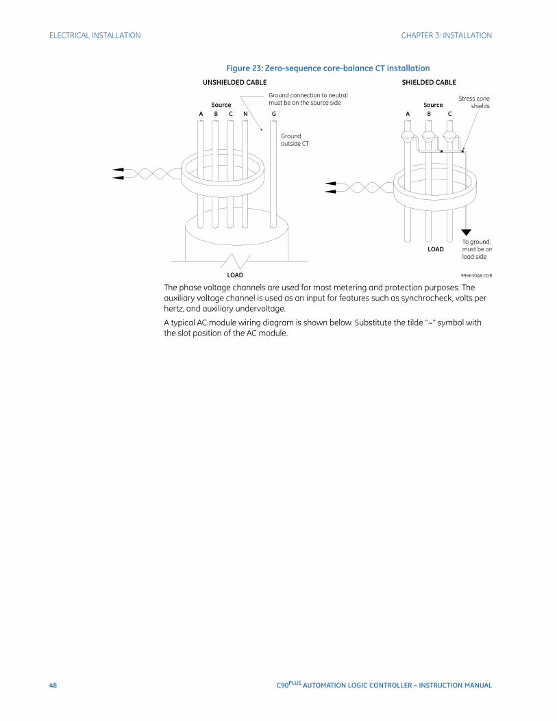
48 C90PLUS AUTOMATION LOGIC CONTROLLER – INSTRUCTION MANUAL
ELECTRICAL INSTALLATION CHAPTER 3: INSTALLATION
Figure 23: Zero-sequence core-balance CT installation
The phase voltage channels are used for most metering and protection purposes. The auxiliary voltage channel is used as an input for features such as synchrocheck, volts per hertz, and auxiliary undervoltage.
A typical AC module wiring diagram is shown below. Substitute the tilde “~” symbol with the slot position of the AC module.
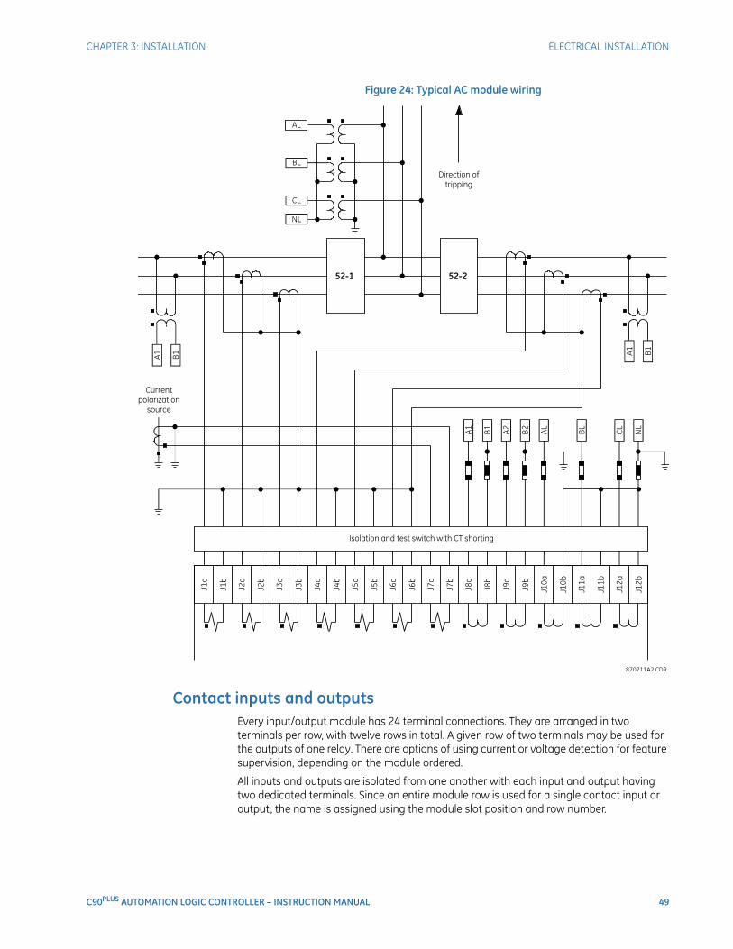
CHAPTER 3: INSTALLATION ELECTRICAL INSTALLATION
C90PLUS AUTOMATION LOGIC CONTROLLER – INSTRUCTION MANUAL 49
Figure 24: Typical AC module wiring
Contact inputs and outputsEvery input/output module has 24 terminal connections. They are arranged in two terminals per row, with twelve rows in total. A given row of two terminals may be used for the outputs of one relay. There are options of using current or voltage detection for feature supervision, depending on the module ordered.
All inputs and outputs are isolated from one another with each input and output having two dedicated terminals. Since an entire module row is used for a single contact input or output, the name is assigned using the module slot position and row number.
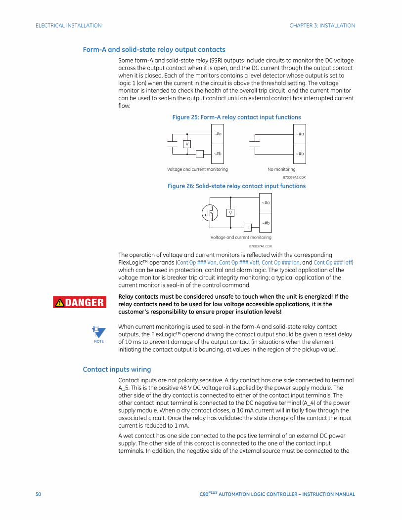
50 C90PLUS AUTOMATION LOGIC CONTROLLER – INSTRUCTION MANUAL
ELECTRICAL INSTALLATION CHAPTER 3: INSTALLATION
Form-A and solid-state relay output contactsSome form-A and solid-state relay (SSR) outputs include circuits to monitor the DC voltage across the output contact when it is open, and the DC current through the output contact when it is closed. Each of the monitors contains a level detector whose output is set to logic 1 (on) when the current in the circuit is above the threshold setting. The voltage monitor is intended to check the health of the overall trip circuit, and the current monitor can be used to seal-in the output contact until an external contact has interrupted current flow.
Figure 25: Form-A relay contact input functions
Figure 26: Solid-state relay contact input functions
The operation of voltage and current monitors is reflected with the corresponding FlexLogic™ operands (Cont Op ### Von, Cont Op ### Voff, Cont Op ### Ion, and Cont Op ### Ioff) which can be used in protection, control and alarm logic. The typical application of the voltage monitor is breaker trip circuit integrity monitoring; a typical application of the current monitor is seal-in of the control command.
DANGER: Relay contacts must be considered unsafe to touch when the unit is energized! If the relay contacts need to be used for low voltage accessible applications, it is the customer’s responsibility to ensure proper insulation levels!
NOTE
NOTE: When current monitoring is used to seal-in the form-A and solid-state relay contact outputs, the FlexLogic™ operand driving the contact output should be given a reset delay of 10 ms to prevent damage of the output contact (in situations when the element initiating the contact output is bouncing, at values in the region of the pickup value).
Contact inputs wiringContact inputs are not polarity sensitive. A dry contact has one side connected to terminal A_5. This is the positive 48 V DC voltage rail supplied by the power supply module. The other side of the dry contact is connected to either of the contact input terminals. The other contact input terminal is connected to the DC negative terminal (A_4) of the power supply module. When a dry contact closes, a 10 mA current will initially flow through the associated circuit. Once the relay has validated the state change of the contact the input current is reduced to 1 mA.
A wet contact has one side connected to the positive terminal of an external DC power supply. The other side of this contact is connected to the one of the contact input terminals. In addition, the negative side of the external source must be connected to the
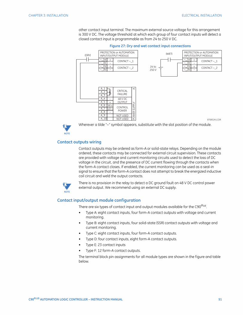
CHAPTER 3: INSTALLATION ELECTRICAL INSTALLATION
C90PLUS AUTOMATION LOGIC CONTROLLER – INSTRUCTION MANUAL 51
other contact input terminal. The maximum external source voltage for this arrangement is 300 V DC. The voltage threshold at which each group of four contact inputs will detect a closed contact input is programmable as from 24 to 250 V DC.
Figure 27: Dry and wet contact input connections
NOTE
NOTE: Wherever a tilde “~” symbol appears, substitute with the slot position of the module.
Contact outputs wiringContact outputs may be ordered as form-A or solid-state relays. Depending on the module ordered, these contacts may be connected for external circuit supervision. These contacts are provided with voltage and current monitoring circuits used to detect the loss of DC voltage in the circuit, and the presence of DC current flowing through the contacts when the form-A contact closes. If enabled, the current monitoring can be used as a seal-in signal to ensure that the form-A contact does not attempt to break the energized inductive coil circuit and weld the output contacts.
NOTE
NOTE: There is no provision in the relay to detect a DC ground fault on 48 V DC control power external output. We recommend using an external DC supply.
Contact input/output module configurationThere are six types of contact input and output modules available for the C90Plus.
• Type A: eight contact inputs, four form-A contact outputs with voltage and current monitoring.
• Type B: eight contact inputs, four solid-state (SSR) contact outputs with voltage and current monitoring.
• Type C: eight contact inputs, four form-A contact outputs.
• Type D: four contact inputs, eight form-A contact outputs.
• Type E: 23 contact inputs
• Type F: 12 form-A contact outputs.
The terminal block pin assignments for all module types are shown in the figure and table below.
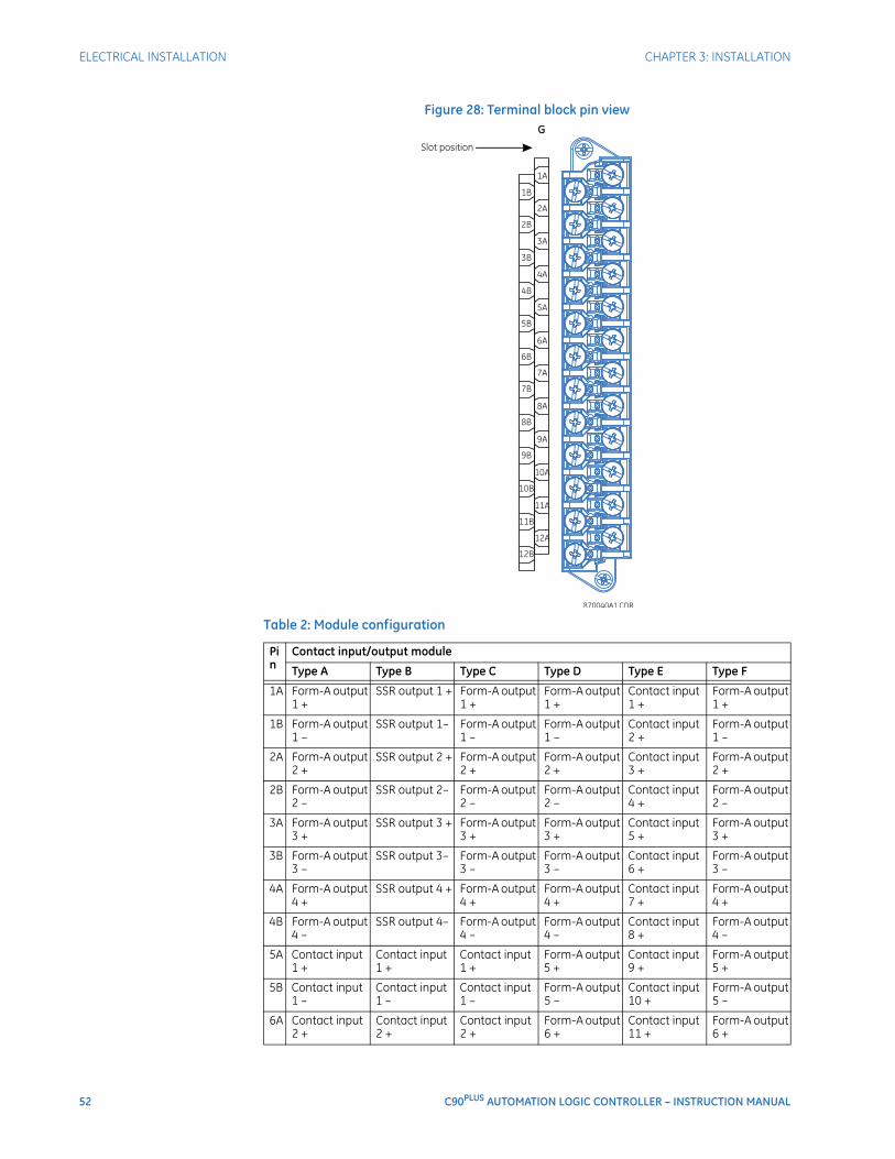
52 C90PLUS AUTOMATION LOGIC CONTROLLER – INSTRUCTION MANUAL
ELECTRICAL INSTALLATION CHAPTER 3: INSTALLATION
Figure 28: Terminal block pin view
Table 2: Module configuration
Pin
Contact input/output module
Type A Type B Type C Type D Type E Type F
1A Form-A output 1 +
SSR output 1 + Form-A output 1 +
Form-A output 1 +
Contact input 1 +
Form-A output 1 +
1B Form-A output 1 –
SSR output 1– Form-A output 1 –
Form-A output 1 –
Contact input 2 +
Form-A output 1 –
2A Form-A output 2 +
SSR output 2 + Form-A output 2 +
Form-A output 2 +
Contact input 3 +
Form-A output 2 +
2B Form-A output 2 –
SSR output 2– Form-A output 2 –
Form-A output 2 –
Contact input 4 +
Form-A output 2 –
3A Form-A output 3 +
SSR output 3 + Form-A output 3 +
Form-A output 3 +
Contact input 5 +
Form-A output 3 +
3B Form-A output 3 –
SSR output 3– Form-A output 3 –
Form-A output 3 –
Contact input 6 +
Form-A output 3 –
4A Form-A output 4 +
SSR output 4 + Form-A output 4 +
Form-A output 4 +
Contact input 7 +
Form-A output 4 +
4B Form-A output 4 –
SSR output 4– Form-A output 4 –
Form-A output 4 –
Contact input 8 +
Form-A output 4 –
5A Contact input 1 +
Contact input 1 +
Contact input 1 +
Form-A output 5 +
Contact input 9 +
Form-A output 5 +
5B Contact input 1 –
Contact input 1 –
Contact input 1 –
Form-A output 5 –
Contact input 10 +
Form-A output 5 –
6A Contact input 2 +
Contact input 2 +
Contact input 2 +
Form-A output 6 +
Contact input 11 +
Form-A output 6 +
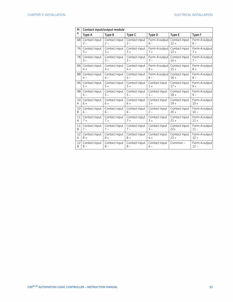
CHAPTER 3: INSTALLATION ELECTRICAL INSTALLATION
C90PLUS AUTOMATION LOGIC CONTROLLER – INSTRUCTION MANUAL 53
6B Contact input 2 –
Contact input 2 –
Contact input 2 –
Form-A output 6 –
Contact input 12 +
Form-A output 6 –
7A Contact input 3 +
Contact input 3 +
Contact input 3 +
Form-A output 7 +
Contact input 13 +
Form-A output 7 +
7B Contact input 3 –
Contact input 3 –
Contact input 3 –
Form-A output 7 –
Contact input 14 +
Form-A output 7 –
8A Contact input 4 +
Contact input 4 +
Contact input 4 +
Form-A output 8 +
Contact input 15 +
Form-A output 8 +
8B Contact input 4 –
Contact input 4 –
Contact input 4 –
Form-A output 8 –
Contact input 16 +
Form-A output 8 –
9A Contact input 5 +
Contact input 5 +
Contact input 5 +
Contact input 1 +
Contact input 17 +
Form-A output 9 +
9B Contact input 5 –
Contact input 5 –
Contact input 5 –
Contact input 1 –
Contact input 18 +
Form-A output 9 –
10A
Contact input 6 +
Contact input 6 +
Contact input 6 +
Contact input 2 +
Contact input 19 +
Form-A output 10 +
10B
Contact input 6 –
Contact input 6 –
Contact input 6 –
Contact input 2 –
Contact input 20 +
Form-A output 10 –
11A
Contact input 7 +
Contact input 7 +
Contact input 7 +
Contact input 3 +
Contact input 21 +
Form-A output 11 +
11B
Contact input 7 –
Contact input 7 –
Contact input 7 –
Contact input 3 –
Contact input 22+
Form-A output 11 –
12A
Contact input 8 +
Contact input 8 +
Contact input 8 +
Contact input 4 +
Contact input 23 +
Form-A output 12 +
12B
Contact input 8 –
Contact input 8 –
Contact input 8 –
Contact input 4 –
Common – Form-A output 12 –
Pin
Contact input/output module
Type A Type B Type C Type D Type E Type F

54 C90PLUS AUTOMATION LOGIC CONTROLLER – INSTRUCTION MANUAL
ELECTRICAL INSTALLATION CHAPTER 3: INSTALLATION
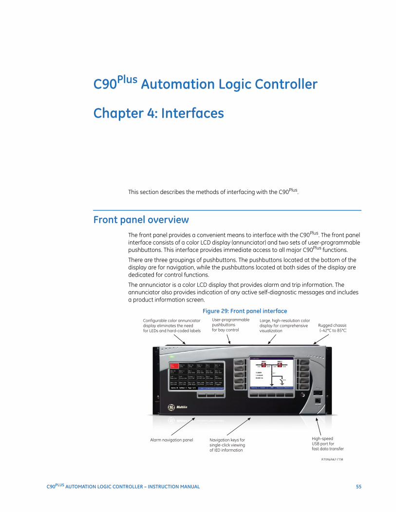
C90PLUS AUTOMATION LOGIC CONTROLLER – INSTRUCTION MANUAL 55
C90Plus Automation Logic Controller
Chapter 4: Interfaces
Interfaces
This section describes the methods of interfacing with the C90Plus.
Front panel overviewThe front panel provides a convenient means to interface with the C90Plus. The front panel interface consists of a color LCD display (annunciator) and two sets of user-programmable pushbuttons. This interface provides immediate access to all major C90Plus functions.
There are three groupings of pushbuttons. The pushbuttons located at the bottom of the display are for navigation, while the pushbuttons located at both sides of the display are dedicated for control functions.
The annunciator is a color LCD display that provides alarm and trip information. The annunciator also provides indication of any active self-diagnostic messages and includes a product information screen.
Figure 29: Front panel interface
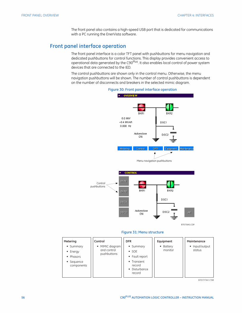
56 C90PLUS AUTOMATION LOGIC CONTROLLER – INSTRUCTION MANUAL
FRONT PANEL OVERVIEW CHAPTER 4: INTERFACES
The front panel also contains a high-speed USB port that is dedicated for communications with a PC running the EnerVista software.
Front panel interface operationThe front panel interface is a color TFT panel with pushbuttons for menu navigation and dedicated pushbuttons for control functions. This display provides convenient access to operational data generated by the C90Plus. It also enables local control of power system devices that are connected to the IED.
The control pushbuttons are shown only in the control menu. Otherwise, the menu navigation pushbuttons will be shown. The number of control pushbuttons is dependent on the number of disconnects and breakers in the selected mimic diagram.
Figure 30: Front panel interface operation
Figure 31: Menu structure
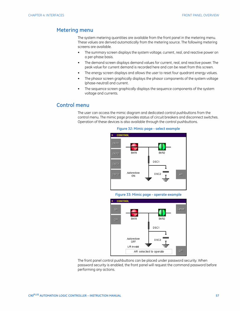
CHAPTER 4: INTERFACES FRONT PANEL OVERVIEW
C90PLUS AUTOMATION LOGIC CONTROLLER – INSTRUCTION MANUAL 57
Metering menuThe system metering quantities are available from the front panel in the metering menu. These values are derived automatically from the metering source. The following metering screens are available.
• The summary screen displays the system voltage, current, real, and reactive power on a per-phase basis.
• The demand screen displays demand values for current, real, and reactive power. The peak value for current demand is recorded here and can be reset from this screen.
• The energy screen displays and allows the user to reset four quadrant energy values.
• The phasor screen graphically displays the phasor components of the system voltage (phase-neutral) and current.
• The sequence screen graphically displays the sequence components of the system voltage and currents.
Control menuThe user can access the mimic diagram and dedicated control pushbuttons from the control menu. The mimic page provides status of circuit breakers and disconnect switches. Operation of these devices is also available through the control pushbuttons.
Figure 32: Mimic page - select example
Figure 33: Mimic page - operate example
The front panel control pushbuttons can be placed under password security. When password security is enabled, the front panel will request the command password before performing any actions.
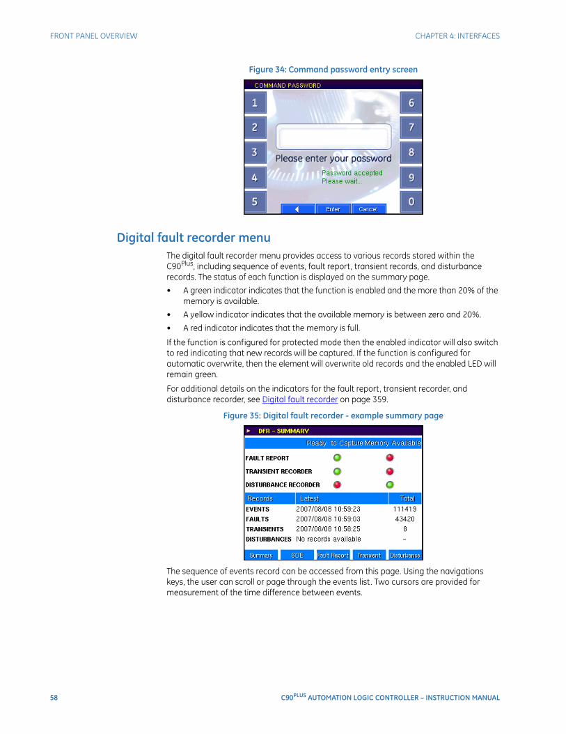
58 C90PLUS AUTOMATION LOGIC CONTROLLER – INSTRUCTION MANUAL
FRONT PANEL OVERVIEW CHAPTER 4: INTERFACES
Figure 34: Command password entry screen
Digital fault recorder menuThe digital fault recorder menu provides access to various records stored within the C90Plus, including sequence of events, fault report, transient records, and disturbance records. The status of each function is displayed on the summary page.
• A green indicator indicates that the function is enabled and the more than 20% of the memory is available.
• A yellow indicator indicates that the available memory is between zero and 20%.
• A red indicator indicates that the memory is full.
If the function is configured for protected mode then the enabled indicator will also switch to red indicating that new records will be captured. If the function is configured for automatic overwrite, then the element will overwrite old records and the enabled LED will remain green.
For additional details on the indicators for the fault report, transient recorder, and disturbance recorder, see Digital fault recorder on page 359.
Figure 35: Digital fault recorder - example summary page
The sequence of events record can be accessed from this page. Using the navigations keys, the user can scroll or page through the events list. Two cursors are provided for measurement of the time difference between events.
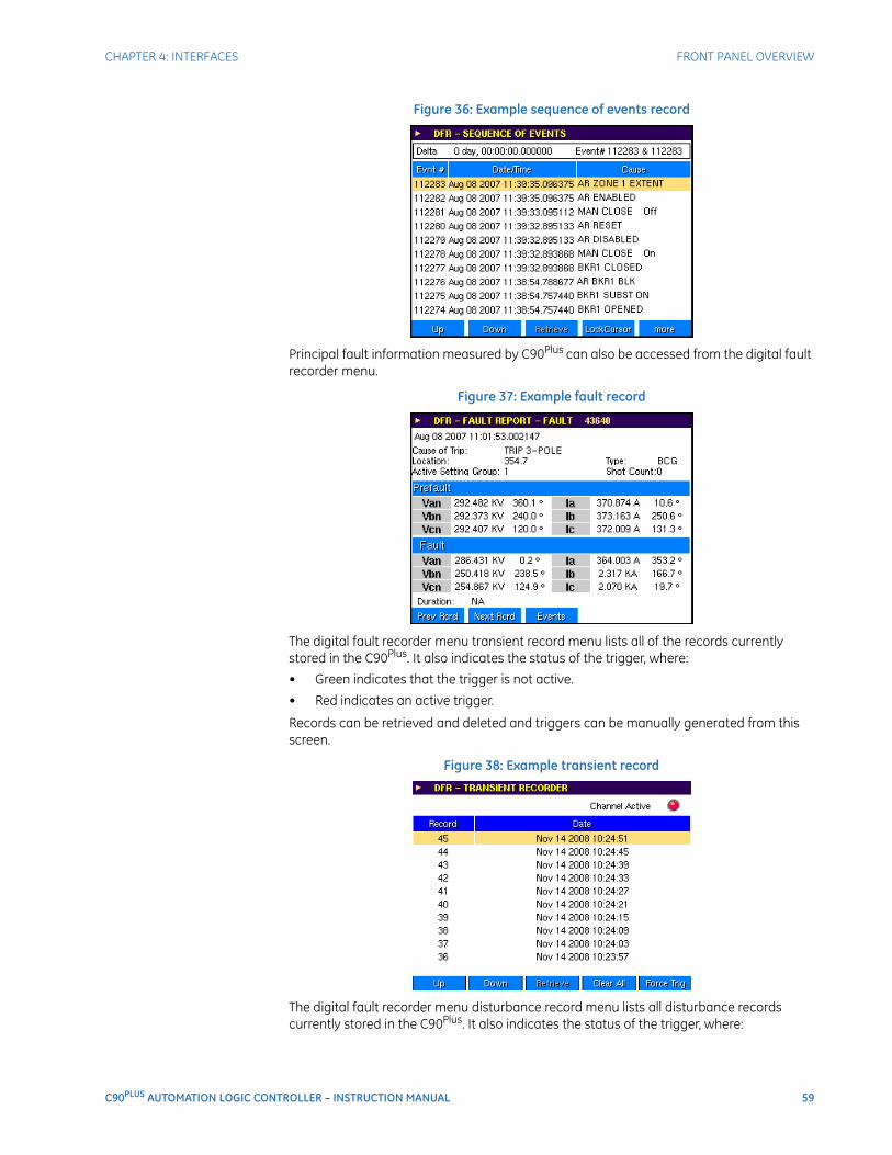
CHAPTER 4: INTERFACES FRONT PANEL OVERVIEW
C90PLUS AUTOMATION LOGIC CONTROLLER – INSTRUCTION MANUAL 59
Figure 36: Example sequence of events record
Principal fault information measured by C90Plus can also be accessed from the digital fault recorder menu.
Figure 37: Example fault record
The digital fault recorder menu transient record menu lists all of the records currently stored in the C90Plus. It also indicates the status of the trigger, where:
• Green indicates that the trigger is not active.
• Red indicates an active trigger.
Records can be retrieved and deleted and triggers can be manually generated from this screen.
Figure 38: Example transient record
The digital fault recorder menu disturbance record menu lists all disturbance records currently stored in the C90Plus. It also indicates the status of the trigger, where:
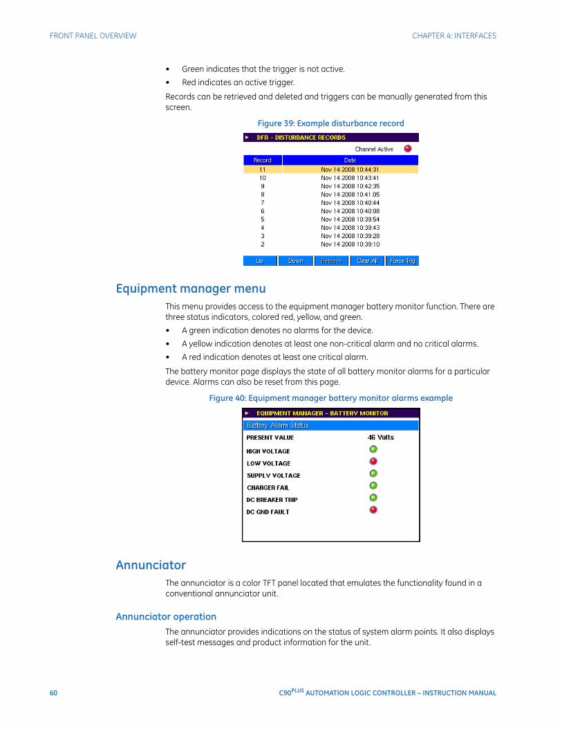
60 C90PLUS AUTOMATION LOGIC CONTROLLER – INSTRUCTION MANUAL
FRONT PANEL OVERVIEW CHAPTER 4: INTERFACES
• Green indicates that the trigger is not active.
• Red indicates an active trigger.
Records can be retrieved and deleted and triggers can be manually generated from this screen.
Figure 39: Example disturbance record
Equipment manager menuThis menu provides access to the equipment manager battery monitor function. There are three status indicators, colored red, yellow, and green.
• A green indication denotes no alarms for the device.
• A yellow indication denotes at least one non-critical alarm and no critical alarms.
• A red indication denotes at least one critical alarm.
The battery monitor page displays the state of all battery monitor alarms for a particular device. Alarms can also be reset from this page.
Figure 40: Equipment manager battery monitor alarms example
AnnunciatorThe annunciator is a color TFT panel located that emulates the functionality found in a conventional annunciator unit.
Annunciator operationThe annunciator provides indications on the status of system alarm points. It also displays self-test messages and product information for the unit.
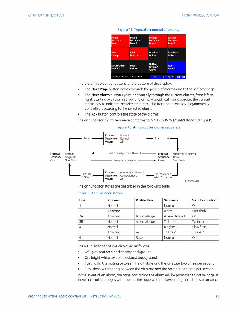
CHAPTER 4: INTERFACES FRONT PANEL OVERVIEW
C90PLUS AUTOMATION LOGIC CONTROLLER – INSTRUCTION MANUAL 61
Figure 41: Typical annunciator display
There are three control buttons at the bottom of the display.
• The Next Page button cycles through the pages of alarms and to the self-test page.
• The Next Alarm button cycles horizontally through the current alarms, from left to right, starting with the first row of alarms. A graphical frame borders the current status box to indicate the selected alarm. The front panel display is dynamically controlled according to the selected alarm.
• The Ack button controls the state of the alarms.
The annunciator alarm sequence conforms to ISA 18.1-1979 (R1992) standard, type R.
Figure 42: Annunciator alarm sequence
The annunciator states are described in the following table.
Table 3: Annunciator states
The visual indications are displayed as follows.
• Off: grey text on a darker grey background.
• On: bright white text on a colored background.
• Fast flash: Alternating between the off state and the on state two times per second.
• Slow flash. Alternating between the off state and the on state one time per second
In the event of an alarm, the page containing the alarm will be promoted to active page. If there are multiple pages with alarms, the page with the lowest page number is promoted.
Line Process Pushbutton Sequence Visual indication
1 Normal --- Normal Off
2 Abnormal --- Alarm Fast flash
3A Abnormal Acknowledge Acknowledged On
3B Normal Acknowledge To line 4 To line 4
4 Normal --- Ringback Slow flash
5 Abnormal --- To line 2 To line 2
6 Normal Reset Normal Off
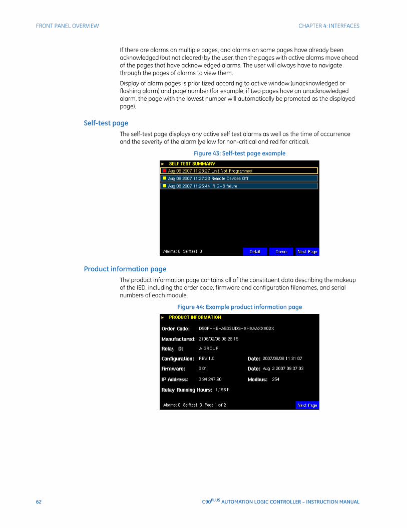
62 C90PLUS AUTOMATION LOGIC CONTROLLER – INSTRUCTION MANUAL
FRONT PANEL OVERVIEW CHAPTER 4: INTERFACES
If there are alarms on multiple pages, and alarms on some pages have already been acknowledged (but not cleared) by the user, then the pages with active alarms move ahead of the pages that have acknowledged alarms. The user will always have to navigate through the pages of alarms to view them.
Display of alarm pages is prioritized according to active window (unacknowledged or flashing alarm) and page number (for example, if two pages have an unacknowledged alarm, the page with the lowest number will automatically be promoted as the displayed page).
Self-test pageThe self-test page displays any active self test alarms as well as the time of occurrence and the severity of the alarm (yellow for non-critical and red for critical).
Figure 43: Self-test page example
Product information pageThe product information page contains all of the constituent data describing the makeup of the IED, including the order code, firmware and configuration filenames, and serial numbers of each module.
Figure 44: Example product information page
C90PLUS AUTOMATION LOGIC CONTROLLER – INSTRUCTION MANUAL 63
C90Plus Automation Logic Controller
Chapter 5: EnerVista software suite
EnerVista software suite
The EnerVista software suite is an industry-leading set of programs that simplifies every aspect of the C90Plus. The EnerVista suite provides tools to monitor the status of your protected asset, maintain the relay, and integrate information measured by the C90Plus into DCS or SCADA monitoring systems. Convenient COMTRADE and sequence of events viewers are an integral part of the EnerVista URPlus Setup software included with every C90Plus. This allows the user to carry out post-mortem event analysis to ensure proper protection system operation.
Introduction to EnerVista URPlus SetupThe EnerVista URPlus Setup software provides a graphical user interface (GUI) that allows users to configure, monitor, maintain and troubleshoot the operation of URPlus-series devices connected locally to a PC or over local or wide area communications networks.The EnerVista URPlus Setup software interface may be initiated in either off-line (not communicating) or on-line (communicating) modes with a URPlus-series device.In off-line mode, a device settings file may be created or configured for eventual downloading to that device. In on-line mode, the settings and actual values of a URPlus-series device can be configured or monitored utilizing real-time communications.
The following screen is displayed upon starting up the EnerVista URPlus Setup software.
Extended EnerVista URPlus Setup featuresThe EnerVista URPlus Setup software contains extended features that compliment the information monitored from URPlus-series devices. These features are not part of the standard C90Plus built-in features. The following sections explain how the EnerVista URPlus Setup software is used to accomplish various advanced monitoring and control features.
Setting templatesSetting file templates simplify the configuration and commissioning of multiple devices that protect similar assets. An example of this is a substation that has 10 similar feeders protected by 10 URPlus-series relays.
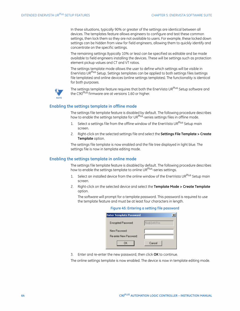
64 C90PLUS AUTOMATION LOGIC CONTROLLER – INSTRUCTION MANUAL
EXTENDED ENERVISTA URPlus SETUP FEATURES CHAPTER 5: ENERVISTA SOFTWARE SUITE
In these situations, typically 90% or greater of the settings are identical between all devices. The templates feature allows engineers to configure and test these common settings, then lock them so they are not available to users. For example, these locked down settings can be hidden from view for field engineers, allowing them to quickly identify and concentrate on the specific settings.
The remaining settings (typically 10% or less) can be specified as editable and be made available to field engineers installing the devices. These will be settings such as protection element pickup values and CT and VT ratios.
The settings template mode allows the user to define which settings will be visible in EnerVista URPlus Setup. Settings templates can be applied to both settings files (settings file templates) and online devices (online settings templates). The functionality is identical for both purposes.
NOTE
NOTE: The settings template feature requires that both the EnerVista URPlus Setup software and the C90Plus firmware are at versions 1.60 or higher.
Enabling the settings template in offline modeThe settings file template feature is disabled by default. The following procedure describes how to enable the settings template for URPlus-series settings files in offline mode.
1. Select a settings file from the offline window of the EnerVista URPlus Setup main screen.
2. Right-click on the selected settings file and select the Settings File Template > Create Template option.
The settings file template is now enabled and the file tree displayed in light blue. The settings file is now in template editing mode.
Enabling the settings template in online modeThe settings file template feature is disabled by default. The following procedure describes how to enable the settings template to online URPlus-series settings.
1. Select an installed device from the online window of the EnerVista URPlus Setup main screen.
2. Right-click on the selected device and select the Template Mode > Create Template option.
The software will prompt for a template password. This password is required to use the template feature and must be at least four characters in length.
Figure 45: Entering a setting file password
3. Enter and re-enter the new password, then click OK to continue.
The online settings template is now enabled. The device is now in template editing mode.
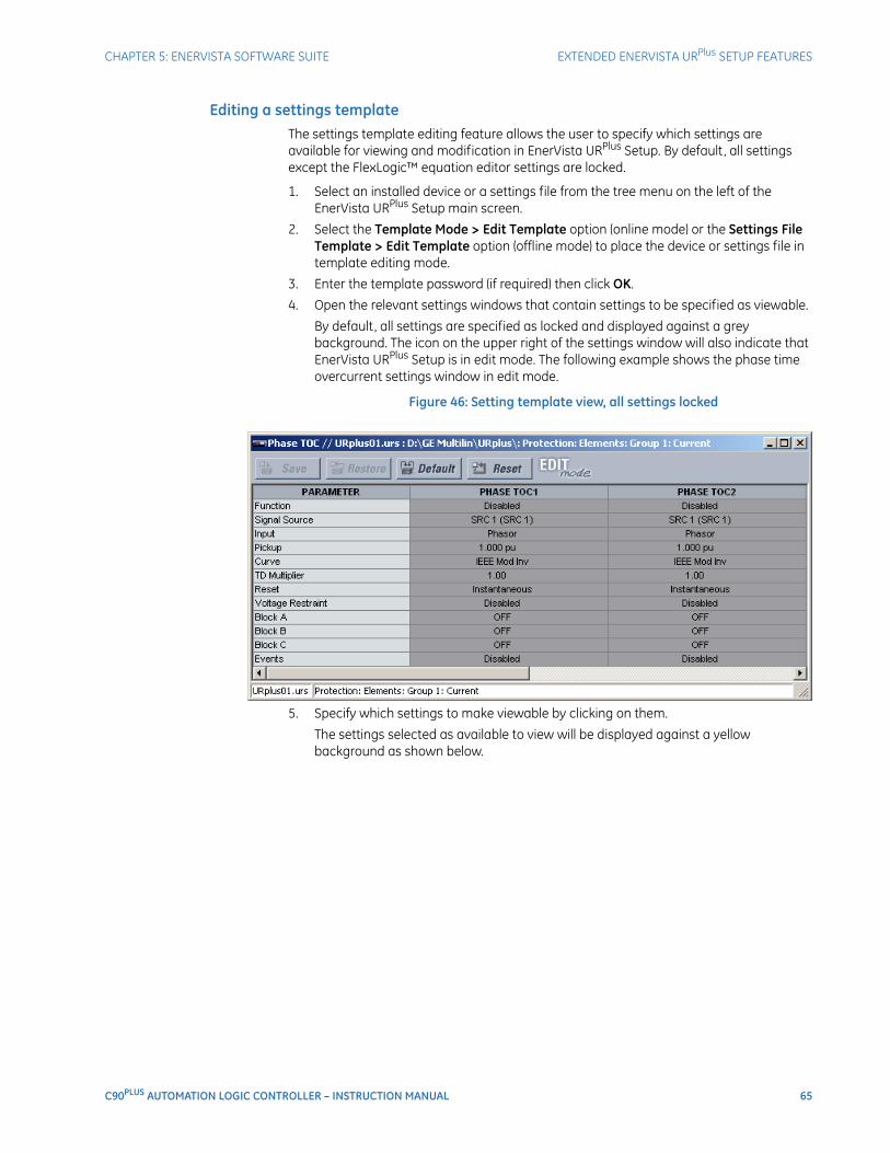
CHAPTER 5: ENERVISTA SOFTWARE SUITE EXTENDED ENERVISTA URPlus SETUP FEATURES
C90PLUS AUTOMATION LOGIC CONTROLLER – INSTRUCTION MANUAL 65
Editing a settings templateThe settings template editing feature allows the user to specify which settings are available for viewing and modification in EnerVista URPlus Setup. By default, all settings except the FlexLogic™ equation editor settings are locked.
1. Select an installed device or a settings file from the tree menu on the left of the EnerVista URPlus Setup main screen.
2. Select the Template Mode > Edit Template option (online mode) or the Settings File Template > Edit Template option (offline mode) to place the device or settings file in template editing mode.
3. Enter the template password (if required) then click OK.
4. Open the relevant settings windows that contain settings to be specified as viewable.
By default, all settings are specified as locked and displayed against a grey background. The icon on the upper right of the settings window will also indicate that EnerVista URPlus Setup is in edit mode. The following example shows the phase time overcurrent settings window in edit mode.
Figure 46: Setting template view, all settings locked
5. Specify which settings to make viewable by clicking on them.
The settings selected as available to view will be displayed against a yellow background as shown below.
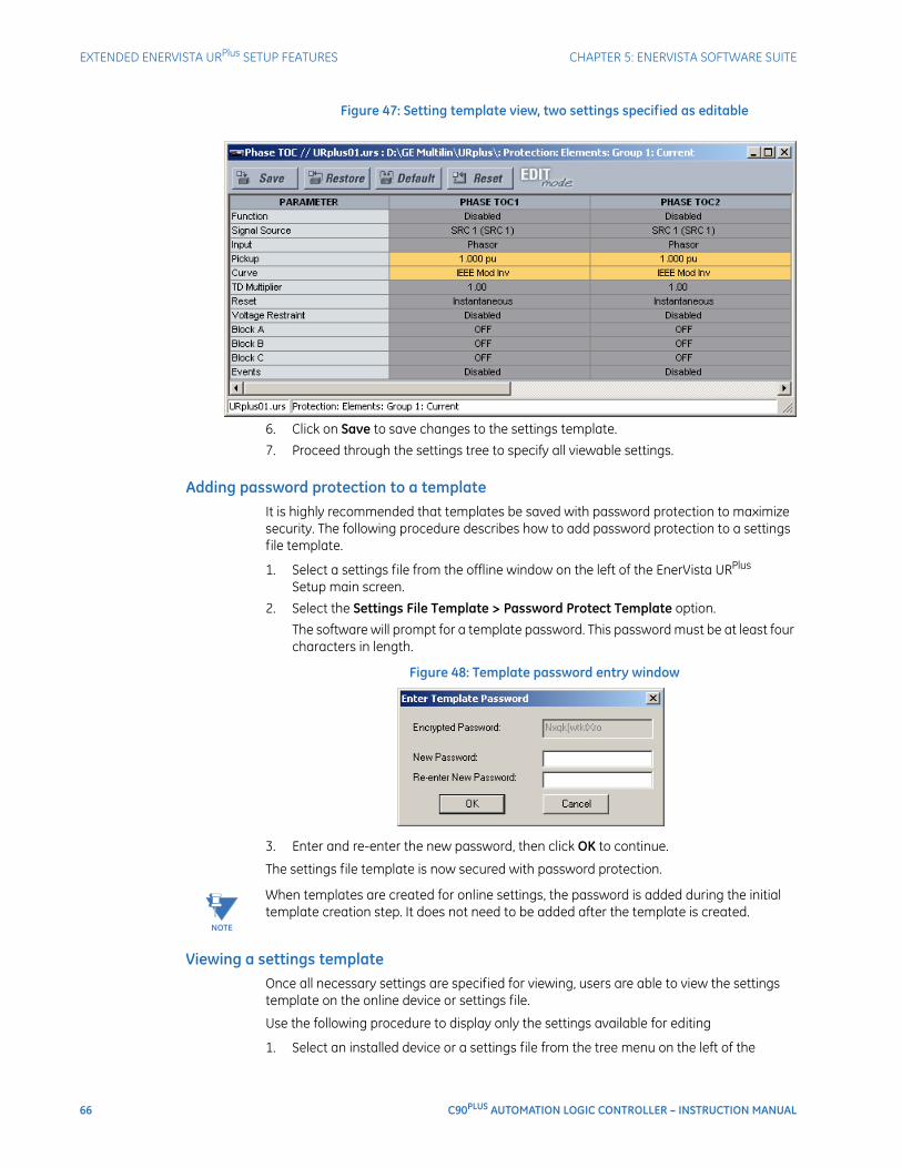
66 C90PLUS AUTOMATION LOGIC CONTROLLER – INSTRUCTION MANUAL
EXTENDED ENERVISTA URPlus SETUP FEATURES CHAPTER 5: ENERVISTA SOFTWARE SUITE
Figure 47: Setting template view, two settings specified as editable
6. Click on Save to save changes to the settings template.
7. Proceed through the settings tree to specify all viewable settings.
Adding password protection to a templateIt is highly recommended that templates be saved with password protection to maximize security. The following procedure describes how to add password protection to a settings file template.
1. Select a settings file from the offline window on the left of the EnerVista URPlus Setup main screen.
2. Select the Settings File Template > Password Protect Template option.
The software will prompt for a template password. This password must be at least four characters in length.
Figure 48: Template password entry window
3. Enter and re-enter the new password, then click OK to continue.
The settings file template is now secured with password protection.
NOTE
NOTE: When templates are created for online settings, the password is added during the initial template creation step. It does not need to be added after the template is created.
Viewing a settings templateOnce all necessary settings are specified for viewing, users are able to view the settings template on the online device or settings file.
Use the following procedure to display only the settings available for editing
1. Select an installed device or a settings file from the tree menu on the left of the
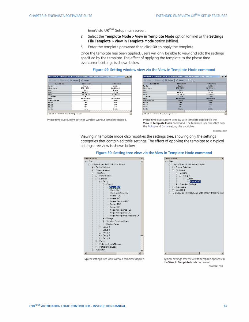
CHAPTER 5: ENERVISTA SOFTWARE SUITE EXTENDED ENERVISTA URPlus SETUP FEATURES
C90PLUS AUTOMATION LOGIC CONTROLLER – INSTRUCTION MANUAL 67
EnerVista URPlus Setup main screen.
2. Select the Template Mode > View in Template Mode option (online) or the Settings File Template > View in Template Mode option (offline).
3. Enter the template password then click OK to apply the template.
Once the template has been applied, users will only be able to view and edit the settings specified by the template. The effect of applying the template to the phase time overcurrent settings is shown below.
Figure 49: Setting window view via the View in Template Mode command
Viewing in template mode also modifies the settings tree, showing only the settings categories that contain editable settings. The effect of applying the template to a typical settings tree view is shown below.
Figure 50: Setting tree view via the View in Template Mode command
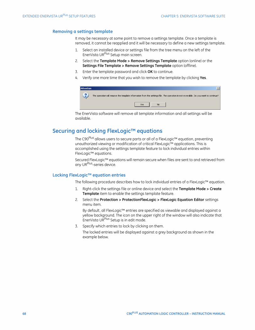
68 C90PLUS AUTOMATION LOGIC CONTROLLER – INSTRUCTION MANUAL
EXTENDED ENERVISTA URPlus SETUP FEATURES CHAPTER 5: ENERVISTA SOFTWARE SUITE
Removing a settings templateIt may be necessary at some point to remove a settings template. Once a template is removed, it cannot be reapplied and it will be necessary to define a new settings template.
1. Select an installed device or settings file from the tree menu on the left of the EnerVista URPlus Setup main screen.
2. Select the Template Mode > Remove Settings Template option (online) or the Settings File Template > Remove Settings Template option (offline).
3. Enter the template password and click OK to continue.
4. Verify one more time that you wish to remove the template by clicking Yes.
The EnerVista software will remove all template information and all settings will be available.
Securing and locking FlexLogic™ equationsThe C90Plus allows users to secure parts or all of a FlexLogic™ equation, preventing unauthorized viewing or modification of critical FlexLogic™ applications. This is accomplished using the settings template feature to lock individual entries within FlexLogic™ equations.
Secured FlexLogic™ equations will remain secure when files are sent to and retrieved from any URPlus-series device.
Locking FlexLogic™ equation entriesThe following procedure describes how to lock individual entries of a FlexLogic™ equation.
1. Right-click the settings file or online device and select the Template Mode > Create Template item to enable the settings template feature.
2. Select the Protection > ProtectionFlexLogic > FlexLogic Equation Editor settings menu item.
By default, all FlexLogic™ entries are specified as viewable and displayed against a yellow background. The icon on the upper right of the window will also indicate that EnerVista URPlus Setup is in edit mode.
3. Specify which entries to lock by clicking on them.
The locked entries will be displayed against a grey background as shown in the example below.
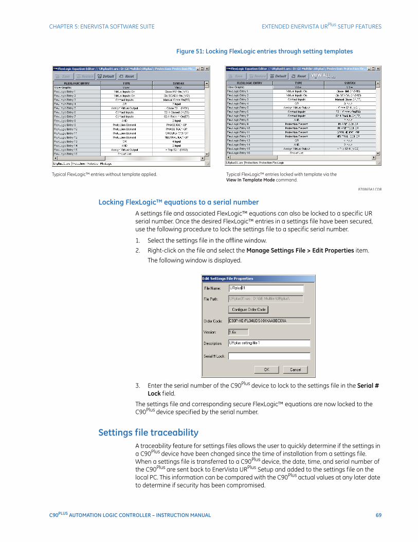
CHAPTER 5: ENERVISTA SOFTWARE SUITE EXTENDED ENERVISTA URPlus SETUP FEATURES
C90PLUS AUTOMATION LOGIC CONTROLLER – INSTRUCTION MANUAL 69
Figure 51: Locking FlexLogic entries through setting templates
Locking FlexLogic™ equations to a serial numberA settings file and associated FlexLogic™ equations can also be locked to a specific UR serial number. Once the desired FlexLogic™ entries in a settings file have been secured, use the following procedure to lock the settings file to a specific serial number.
1. Select the settings file in the offline window.
2. Right-click on the file and select the Manage Settings File > Edit Properties item.
The following window is displayed.
3. Enter the serial number of the C90Plus device to lock to the settings file in the Serial # Lock field.
The settings file and corresponding secure FlexLogic™ equations are now locked to the C90Plus device specified by the serial number.
Settings file traceabilityA traceability feature for settings files allows the user to quickly determine if the settings in a C90Plus device have been changed since the time of installation from a settings file. When a settings file is transferred to a C90Plus device, the date, time, and serial number of the C90Plus are sent back to EnerVista URPlus Setup and added to the settings file on the local PC. This information can be compared with the C90Plus actual values at any later date to determine if security has been compromised.
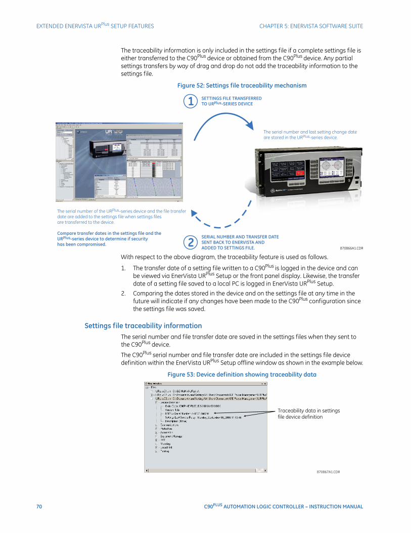
70 C90PLUS AUTOMATION LOGIC CONTROLLER – INSTRUCTION MANUAL
EXTENDED ENERVISTA URPlus SETUP FEATURES CHAPTER 5: ENERVISTA SOFTWARE SUITE
The traceability information is only included in the settings file if a complete settings file is either transferred to the C90Plus device or obtained from the C90Plus device. Any partial settings transfers by way of drag and drop do not add the traceability information to the settings file.
Figure 52: Settings file traceability mechanism
With respect to the above diagram, the traceability feature is used as follows.
1. The transfer date of a setting file written to a C90Plus is logged in the device and can be viewed via EnerVista URPlus Setup or the front panel display. Likewise, the transfer date of a setting file saved to a local PC is logged in EnerVista URPlus Setup.
2. Comparing the dates stored in the device and on the settings file at any time in the future will indicate if any changes have been made to the C90Plus configuration since the settings file was saved.
Settings file traceability informationThe serial number and file transfer date are saved in the settings files when they sent to the C90Plus device.
The C90Plus serial number and file transfer date are included in the settings file device definition within the EnerVista URPlus Setup offline window as shown in the example below.
Figure 53: Device definition showing traceability data
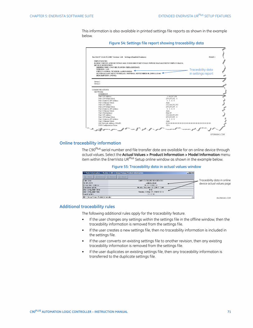
CHAPTER 5: ENERVISTA SOFTWARE SUITE EXTENDED ENERVISTA URPlus SETUP FEATURES
C90PLUS AUTOMATION LOGIC CONTROLLER – INSTRUCTION MANUAL 71
This information is also available in printed settings file reports as shown in the example below.
Figure 54: Settings file report showing traceability data
Online traceability informationThe C90Plus serial number and file transfer date are available for an online device through actual values. Select the Actual Values > Product Information > Model Information menu item within the EnerVista URPlus Setup online window as shown in the example below.
Figure 55: Traceability data in actual values window
Additional traceability rulesThe following additional rules apply for the traceability feature.
• If the user changes any settings within the settings file in the offline window, then the traceability information is removed from the settings file.
• If the user creates a new settings file, then no traceability information is included in the settings file.
• If the user converts an existing settings file to another revision, then any existing traceability information is removed from the settings file.
• If the user duplicates an existing settings file, then any traceability information is transferred to the duplicate settings file.

72 C90PLUS AUTOMATION LOGIC CONTROLLER – INSTRUCTION MANUAL
EXTENDED ENERVISTA URPlus SETUP FEATURES CHAPTER 5: ENERVISTA SOFTWARE SUITE
C90PLUS AUTOMATION LOGIC CONTROLLER – INSTRUCTION MANUAL 73
C90Plus Automation Logic Controller
Chapter 6: Communications
Communications
This section describes how to program the C90Plus communications settings.
Communications overviewThe C90Plus has one Ethernet port (port 1) on the main CPU module and two additional Ethernet ports (ports 2 and 3) on the communications module. Each port supports 100Base-FX over multi-mode fiber and 10/100Base-TX over twisted-pair, with auto-negotiation. Port 1 is primarily intended for configuration and file retrieval purposes and has a dedicated IP address. Ports 2 and 3 are intended for SCADA and peer-to-peer messaging. Additionally, there is one serial RS485 port. The following protocols are available, depending on the configuration of the unit.
• Ethernet port 1: Modbus TCP.
• Ethernet port 2: Modbus TCP, DNP 3.0, IEC 60870-5-104, IEC 61850.
• Ethernet port 3: Modbus TCP, DNP 3.0, IEC 60870-5-104, IEC 61850.
• RS485 port: Modbus, DNP 3.0.
Network topologyThe topology shown below allows several C90Plus devices to communicate with a PC running EnerVista software or with a gateway for remote access. This allows device configuration, monitoring, and file transfers (transient records, sequence of events, etc.) to be carried out over Ethernet. Communications processor cards are not required and no redundancy is provided.
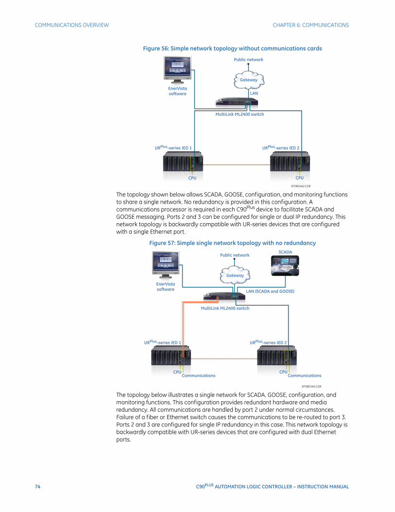
74 C90PLUS AUTOMATION LOGIC CONTROLLER – INSTRUCTION MANUAL
COMMUNICATIONS OVERVIEW CHAPTER 6: COMMUNICATIONS
Figure 56: Simple network topology without communications cards
The topology shown below allows SCADA, GOOSE, configuration, and monitoring functions to share a single network. No redundancy is provided in this configuration. A communications processor is required in each C90Plus device to facilitate SCADA and GOOSE messaging. Ports 2 and 3 can be configured for single or dual IP redundancy. This network topology is backwardly compatible with UR-series devices that are configured with a single Ethernet port.
Figure 57: Simple single network topology with no redundancy
The topology below illustrates a single network for SCADA, GOOSE, configuration, and monitoring functions. This configuration provides redundant hardware and media redundancy. All communications are handled by port 2 under normal circumstances. Failure of a fiber or Ethernet switch causes the communications to be re-routed to port 3. Ports 2 and 3 are configured for single IP redundancy in this case. This network topology is backwardly compatible with UR-series devices that are configured with dual Ethernet ports.
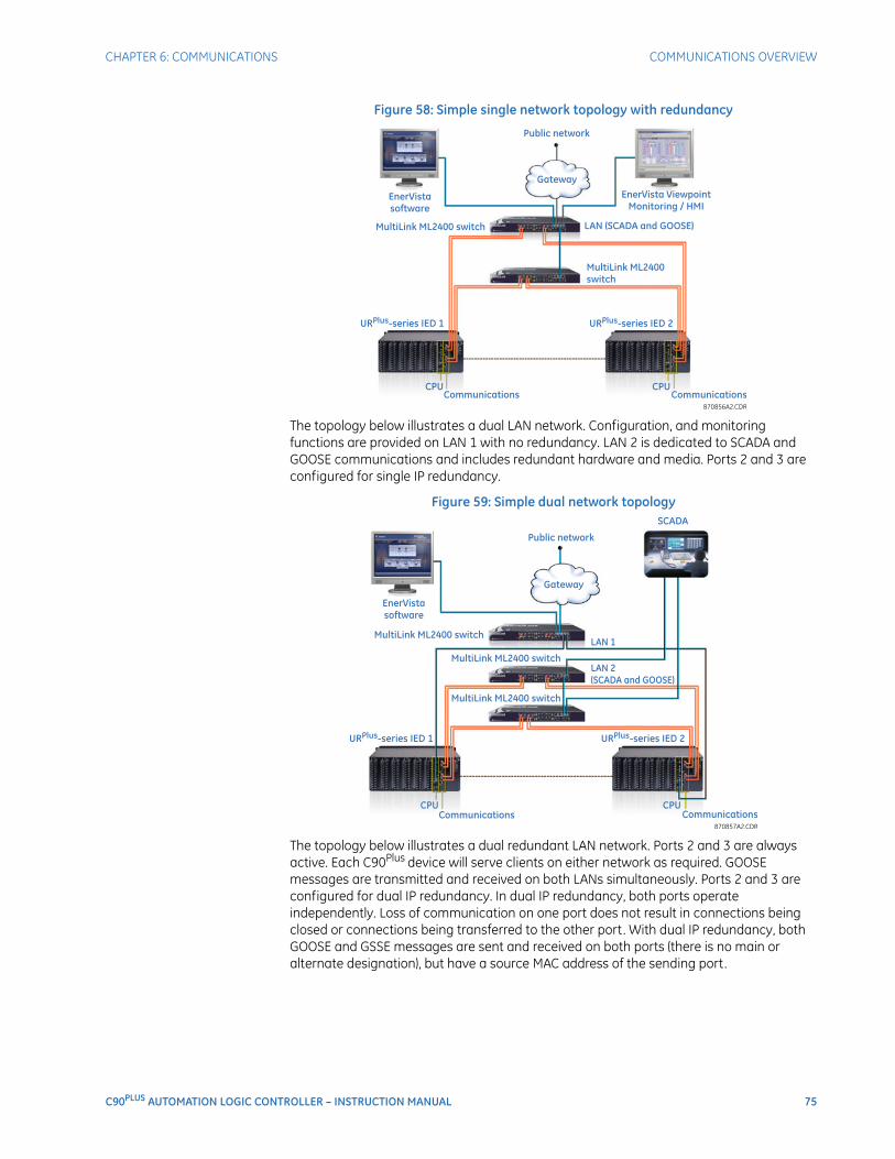
CHAPTER 6: COMMUNICATIONS COMMUNICATIONS OVERVIEW
C90PLUS AUTOMATION LOGIC CONTROLLER – INSTRUCTION MANUAL 75
Figure 58: Simple single network topology with redundancy
The topology below illustrates a dual LAN network. Configuration, and monitoring functions are provided on LAN 1 with no redundancy. LAN 2 is dedicated to SCADA and GOOSE communications and includes redundant hardware and media. Ports 2 and 3 are configured for single IP redundancy.
Figure 59: Simple dual network topology
The topology below illustrates a dual redundant LAN network. Ports 2 and 3 are always active. Each C90Plus device will serve clients on either network as required. GOOSE messages are transmitted and received on both LANs simultaneously. Ports 2 and 3 are configured for dual IP redundancy. In dual IP redundancy, both ports operate independently. Loss of communication on one port does not result in connections being closed or connections being transferred to the other port. With dual IP redundancy, both GOOSE and GSSE messages are sent and received on both ports (there is no main or alternate designation), but have a source MAC address of the sending port.
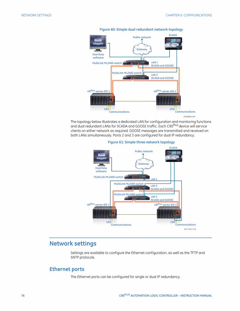
76 C90PLUS AUTOMATION LOGIC CONTROLLER – INSTRUCTION MANUAL
NETWORK SETTINGS CHAPTER 6: COMMUNICATIONS
Figure 60: Simple dual redundant network topology
The topology below illustrates a dedicated LAN for configuration and monitoring functions and dual redundant LANs for SCADA and GOOSE traffic. Each C90Plus device will service clients on either network as required. GOOSE messages are transmitted and received on both LANs simultaneously. Ports 2 and 3 are configured for dual IP redundancy.
Figure 61: Simple three network topology
Network settingsSettings are available to configure the Ethernet configuration, as well as the TFTP and SNTP protocols.
Ethernet portsThe Ethernet ports can be configured for single or dual IP redundancy.
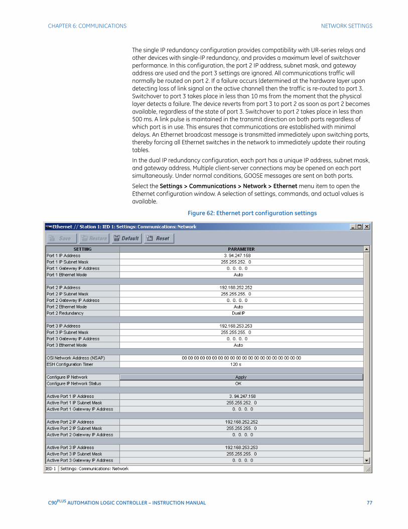
CHAPTER 6: COMMUNICATIONS NETWORK SETTINGS
C90PLUS AUTOMATION LOGIC CONTROLLER – INSTRUCTION MANUAL 77
The single IP redundancy configuration provides compatibility with UR-series relays and other devices with single-IP redundancy, and provides a maximum level of switchover performance. In this configuration, the port 2 IP address, subnet mask, and gateway address are used and the port 3 settings are ignored. All communications traffic will normally be routed on port 2. If a failure occurs (determined at the hardware layer upon detecting loss of link signal on the active channel) then the traffic is re-routed to port 3. Switchover to port 3 takes place in less than 10 ms from the moment that the physical layer detects a failure. The device reverts from port 3 to port 2 as soon as port 2 becomes available, regardless of the state of port 3. Switchover to port 2 takes place in less than 500 ms. A link pulse is maintained in the transmit direction on both ports regardless of which port is in use. This ensures that communications are established with minimal delays. An Ethernet broadcast message is transmitted immediately upon switching ports, thereby forcing all Ethernet switches in the network to immediately update their routing tables.
In the dual IP redundancy configuration, each port has a unique IP address, subnet mask, and gateway address. Multiple client-server connections may be opened on each port simultaneously. Under normal conditions, GOOSE messages are sent on both ports.
Select the Settings > Communications > Network > Ethernet menu item to open the Ethernet configuration window. A selection of settings, commands, and actual values is available.
Figure 62: Ethernet port configuration settings

78 C90PLUS AUTOMATION LOGIC CONTROLLER – INSTRUCTION MANUAL
NETWORK SETTINGS CHAPTER 6: COMMUNICATIONS
The IP addresses are used with the DNP, Modbus/TCP, IEC 61580, IEC 60870-5-104 and TFTP protocols.
NOTE
NOTE: When the NSAP address or any user map setting (when used with DNP) is changed, it will not become active until power to the relay has been cycled (off-to-on).
The following settings are available for each Ethernet port, except for OSI Network Address (NSAP) and ESH Configuration Time, which are not port-specific, and the Port 2 Redundancy, which applies only to Ethernet port 2.
Port 1 IP Address, Port 2 IP Address, Port 3 IP AddressRange: standard IP address rangeDefault: 192.168.251.251 (port 1), 192.168.252.252 (port 2), 192.168.253.253 (port 3)
These settings specify the dedicated IP address for each Ethernet port. When using multiple Ethernet ports, each port must be configured for a different subnet.
Port 1 IP Subnet Mask, Port 2 IP Subnet Mask, Port 3 IP Subnet MaskRange: standard IP address rangeDefault: 255.255.255.0
These settings specify the dedicated subnet mask for each Ethernet port.
The subnet mask settings for ports 2 and 3 are available only when the C90Plus contains a communications card. The subnet mask setting for port 3 is not available when the Port 2 Redundancy setting is “Dual IP”.
Port 1 Gateway IP Address, Port 2 Gateway IP Address, Port 3 Gateway IP AddressRange: standard IP address rangeDefault: 0.0.0.0
These settings specify the dedicated gateway address for the selected Ethernet port.
The gateway IP address settings for ports 2 and 3 are available only when the C90Plus contains a communications card. The gateway IP address setting for port 3 is not available when the Port 2 Redundancy setting is “Dual IP”.
Port 1 Ethernet Mode, Port 2 Ethernet Mode, Port 3 Ethernet ModeRange: Auto, 10/100 Base-TX, 100 Base-TXDefault: Auto
These settings select the Ethernet connection hardware type, either 10/100Base-TX (twisted-pair) or 100Base-FX (fiber optic). The “Auto” selection is used to automatically detect the Ethernet hardware type.
The Ethernet mode settings for ports 2 and 3 are available only when the C90Plus contains a communications card. The Ethernet mode setting for port 3 is not available when the Port 2 Redundancy setting is “Dual IP”.
Port 2 RedundancyRange: Single IP, Dual IPDefault: Dual IP
This settings selects single-IP or dual-IP operation for Ethernet ports 2 and 3. In single-IP mode, the link status of both ports is continuously monitored but only one port is active at a time. Each port uses the same source MAC address and IP parameters specified for Ethernet port #2. In dual-IP mode, Ethernet ports 2 and 3 operate independently with their own MAC addresses and IP parameters. Changes to this setting are implemented immediately.
This setting is available only when the C90Plus contains a communications card.

CHAPTER 6: COMMUNICATIONS NETWORK SETTINGS
C90PLUS AUTOMATION LOGIC CONTROLLER – INSTRUCTION MANUAL 79
OSI Network Address (NSAP)Range: 20 alphanumeric charactersDefault: 00 00 00 00 00 00 00 00 00 00 00 00 00 00 00 00 49 00 00 00
This setting specifies the NSAP address used with the IEC 61850 protocol over the OSI (CLNP/TP4) stack.
ESH Configuration TimerRange: 0 to 32767 seconds in steps of 1Default: 120 seconds
The End System to Intermediate System Routing Exchange protocol used with ISO 8473 mandates that the end system construct and transmit an End System Hello (ESH) signal for each NSAP it serves, based on an internal timer. This setting specifies the transmission time for the ESH signal. This setting takes affect when the C90Plus is rebooted.
The following command is also available from this window.
Configure IP NetworkURPlus-series command
This command validates the IP address, subnet mask, and gateway IP address settings for all ports. If the validation is successful, then the Configure IP Network Status value will be “OK” and the new settings will take effect immediately. If the validation fails, then the Configure IP Network Status value will indicate the reason for failure and the network settings will be restored to their previous values.
The following actual values are also available from this window.
Configure IP Network StatusRange: OK, PORT 1 NETMASK ERROR, PORT 2 NETMASK ERROR, PORT 3 NETMASK ERROR, PORT 1 IP ADDR RSVD, PORT 2 IP ADDR RSVD, PORT 3 IP ADDR RSVD, PORT 1 IP ADDR LPBK, PORT 2 IP ADDR LPBK, PORT 3 IP ADDR LPBK, PORT 1 IP ADDR NETWK, PORT 2 IP ADDR NETWK, PORT 3 IP ADDR NETWK, PRT 1-2 SUBNET OVRLP, PRT 1-3 SUBNET OVRLP, PRT 2-3 SUBNET OVRLP, >1 GATEWAY DEFINED
This actual value displays the status of the Configure IP Network command. The following status values are indicated.
– “OK”: All supplied user IP parameters are valid and have been applied to the network stack.
– “PORT 1 NETMASK ERROR”, “PORT 2 NETMASK ERROR”, “PORT 3 NETMASK ERROR”: An invalid network mask value was entered for Ethernet port 1, 2, or 3, respectively.
– “PORT 1 IP ADDR RSVD”, “PORT 2 IP ADDR RSVD”, “PORT 3 IP ADDR RSVD”: A reserved IP address was entered for Ethernet port 1, 2, or 3, respectively. Reserved IP addresses include 0.---.---.--- (for self-identification), 224.---.---.--- through 239.---.---.--- (multicast), and 240.---.---.--- through 255.---.---.--- (reserved by IANA).
– “PORT 1 IP ADDR LPBK”, “PORT 2 IP ADDR LPBK”, “PORT 3 IP ADDR LPBK”: A loopback IP address was entered for Ethernet port 1, 2, or 3, respectively.
– “PORT 1 IP ADDR NETWK”, “PORT 2 IP ADDR NETWK”, “PORT 3 IP ADDR NETWK”: The entered IP address is the network address for Ethernet port 1, 2, or 3, respectively.
– “PRT 1-2 SUBNET OVRLP”: The entered network parameters for Ethernet port 1 overlap the network parameters for Ethernet port 2.
– “PRT 1-3 SUBNET OVRLP”: The entered network parameters for Ethernet port 1 overlap the network parameters for Ethernet port 3.
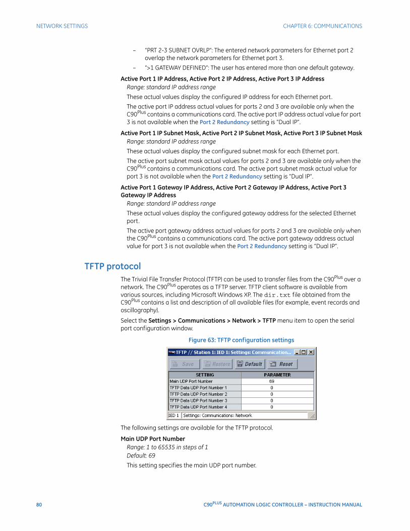
80 C90PLUS AUTOMATION LOGIC CONTROLLER – INSTRUCTION MANUAL
NETWORK SETTINGS CHAPTER 6: COMMUNICATIONS
– “PRT 2-3 SUBNET OVRLP”: The entered network parameters for Ethernet port 2 overlap the network parameters for Ethernet port 3.
– “>1 GATEWAY DEFINED”: The user has entered more than one default gateway.
Active Port 1 IP Address, Active Port 2 IP Address, Active Port 3 IP AddressRange: standard IP address range
These actual values display the configured IP address for each Ethernet port.
The active port IP address actual values for ports 2 and 3 are available only when the C90Plus contains a communications card. The active port IP address actual value for port 3 is not available when the Port 2 Redundancy setting is “Dual IP”.
Active Port 1 IP Subnet Mask, Active Port 2 IP Subnet Mask, Active Port 3 IP Subnet MaskRange: standard IP address range
These actual values display the configured subnet mask for each Ethernet port.
The active port subnet mask actual values for ports 2 and 3 are available only when the C90Plus contains a communications card. The active port subnet mask actual value for port 3 is not available when the Port 2 Redundancy setting is “Dual IP”.
Active Port 1 Gateway IP Address, Active Port 2 Gateway IP Address, Active Port 3 Gateway IP Address
Range: standard IP address range
These actual values display the configured gateway address for the selected Ethernet port.
The active port gateway address actual values for ports 2 and 3 are available only when the C90Plus contains a communications card. The active port gateway address actual value for port 3 is not available when the Port 2 Redundancy setting is “Dual IP”.
TFTP protocolThe Trivial File Transfer Protocol (TFTP) can be used to transfer files from the C90Plus over a network. The C90Plus operates as a TFTP server. TFTP client software is available from various sources, including Microsoft Windows XP. The dir.txt file obtained from the C90Plus contains a list and description of all available files (for example, event records and oscillography).
Select the Settings > Communications > Network > TFTP menu item to open the serial port configuration window.
Figure 63: TFTP configuration settings
The following settings are available for the TFTP protocol.
Main UDP Port NumberRange: 1 to 65535 in steps of 1Default: 69
This setting specifies the main UDP port number.
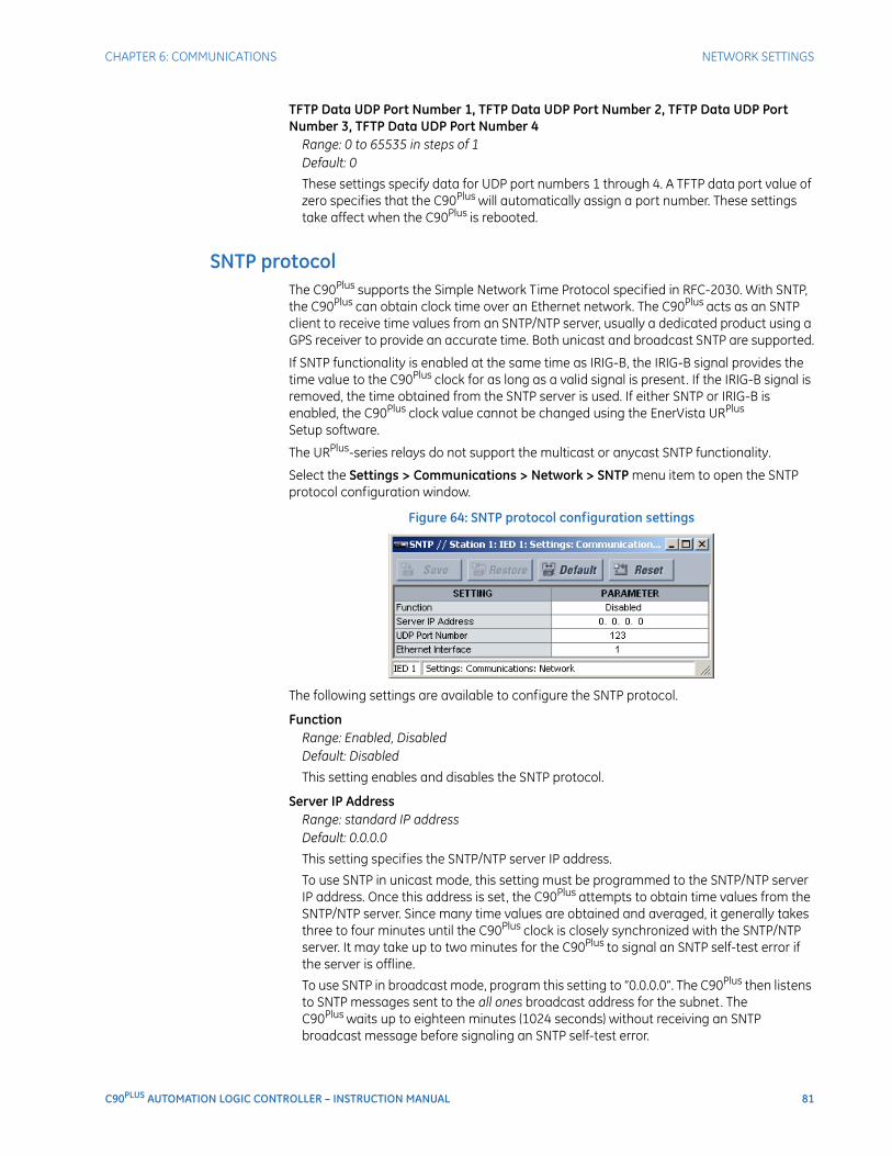
CHAPTER 6: COMMUNICATIONS NETWORK SETTINGS
C90PLUS AUTOMATION LOGIC CONTROLLER – INSTRUCTION MANUAL 81
TFTP Data UDP Port Number 1, TFTP Data UDP Port Number 2, TFTP Data UDP Port Number 3, TFTP Data UDP Port Number 4
Range: 0 to 65535 in steps of 1Default: 0
These settings specify data for UDP port numbers 1 through 4. A TFTP data port value of zero specifies that the C90Plus will automatically assign a port number. These settings take affect when the C90Plus is rebooted.
SNTP protocolThe C90Plus supports the Simple Network Time Protocol specified in RFC-2030. With SNTP, the C90Plus can obtain clock time over an Ethernet network. The C90Plus acts as an SNTP client to receive time values from an SNTP/NTP server, usually a dedicated product using a GPS receiver to provide an accurate time. Both unicast and broadcast SNTP are supported.
If SNTP functionality is enabled at the same time as IRIG-B, the IRIG-B signal provides the time value to the C90Plus clock for as long as a valid signal is present. If the IRIG-B signal is removed, the time obtained from the SNTP server is used. If either SNTP or IRIG-B is enabled, the C90Plus clock value cannot be changed using the EnerVista URPlus Setup software.
The URPlus-series relays do not support the multicast or anycast SNTP functionality.
Select the Settings > Communications > Network > SNTP menu item to open the SNTP protocol configuration window.
Figure 64: SNTP protocol configuration settings
The following settings are available to configure the SNTP protocol.
FunctionRange: Enabled, DisabledDefault: Disabled
This setting enables and disables the SNTP protocol.
Server IP AddressRange: standard IP addressDefault: 0.0.0.0
This setting specifies the SNTP/NTP server IP address.
To use SNTP in unicast mode, this setting must be programmed to the SNTP/NTP server IP address. Once this address is set, the C90Plus attempts to obtain time values from the SNTP/NTP server. Since many time values are obtained and averaged, it generally takes three to four minutes until the C90Plus clock is closely synchronized with the SNTP/NTP server. It may take up to two minutes for the C90Plus to signal an SNTP self-test error if the server is offline.
To use SNTP in broadcast mode, program this setting to “0.0.0.0”. The C90Plus then listens to SNTP messages sent to the all ones broadcast address for the subnet. The C90Plus waits up to eighteen minutes (1024 seconds) without receiving an SNTP broadcast message before signaling an SNTP self-test error.
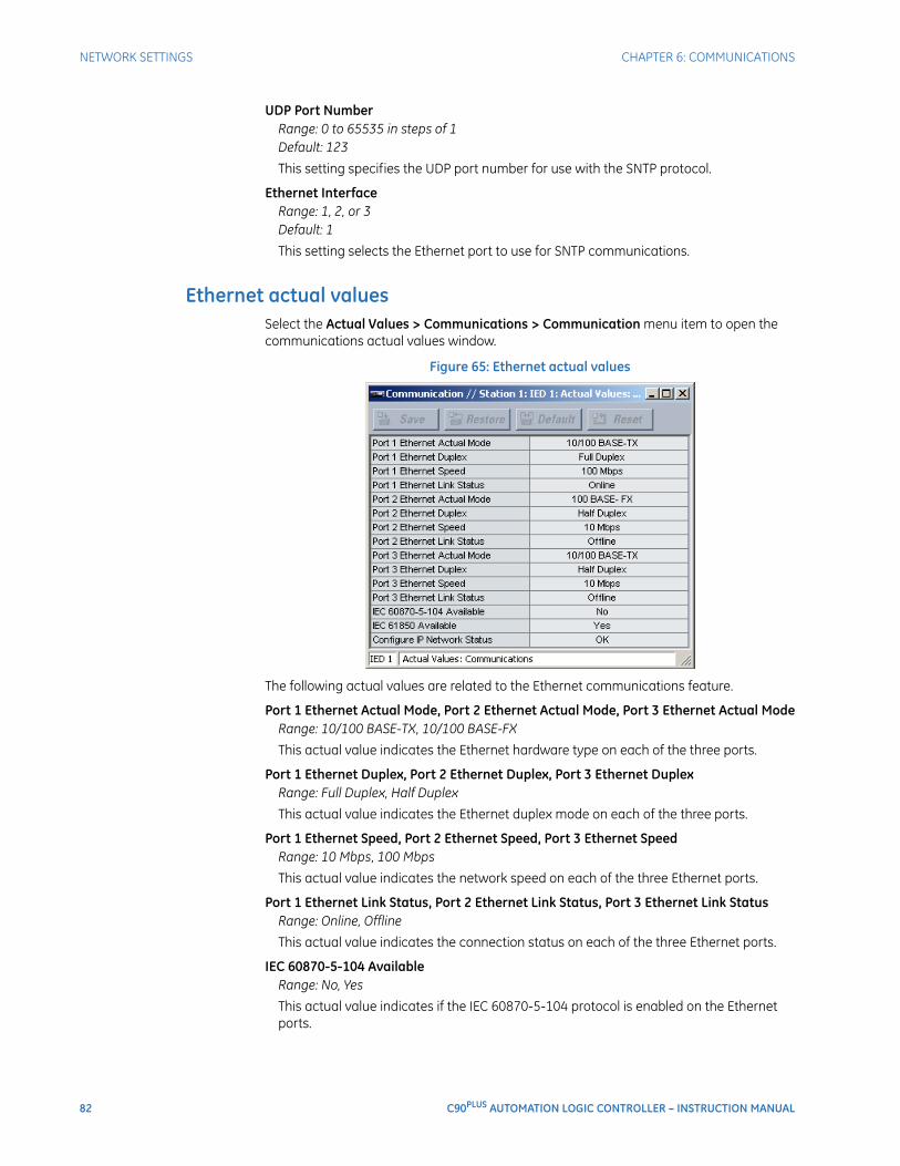
82 C90PLUS AUTOMATION LOGIC CONTROLLER – INSTRUCTION MANUAL
NETWORK SETTINGS CHAPTER 6: COMMUNICATIONS
UDP Port NumberRange: 0 to 65535 in steps of 1Default: 123
This setting specifies the UDP port number for use with the SNTP protocol.
Ethernet InterfaceRange: 1, 2, or 3Default: 1
This setting selects the Ethernet port to use for SNTP communications.
Ethernet actual valuesSelect the Actual Values > Communications > Communication menu item to open the communications actual values window.
Figure 65: Ethernet actual values
The following actual values are related to the Ethernet communications feature.
Port 1 Ethernet Actual Mode, Port 2 Ethernet Actual Mode, Port 3 Ethernet Actual ModeRange: 10/100 BASE-TX, 10/100 BASE-FX
This actual value indicates the Ethernet hardware type on each of the three ports.
Port 1 Ethernet Duplex, Port 2 Ethernet Duplex, Port 3 Ethernet DuplexRange: Full Duplex, Half Duplex
This actual value indicates the Ethernet duplex mode on each of the three ports.
Port 1 Ethernet Speed, Port 2 Ethernet Speed, Port 3 Ethernet SpeedRange: 10 Mbps, 100 Mbps
This actual value indicates the network speed on each of the three Ethernet ports.
Port 1 Ethernet Link Status, Port 2 Ethernet Link Status, Port 3 Ethernet Link StatusRange: Online, Offline
This actual value indicates the connection status on each of the three Ethernet ports.
IEC 60870-5-104 AvailableRange: No, Yes
This actual value indicates if the IEC 60870-5-104 protocol is enabled on the Ethernet ports.
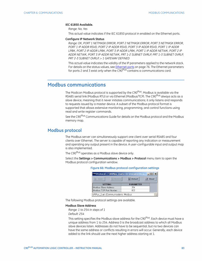
CHAPTER 6: COMMUNICATIONS MODBUS COMMUNICATIONS
C90PLUS AUTOMATION LOGIC CONTROLLER – INSTRUCTION MANUAL 83
IEC 61850 Available.Range: No, Yes
This actual value indicates if the IEC 61850 protocol in enabled on the Ethernet ports.
Configure IP Network StatusRange: OK, PORT 1 NETMASK ERROR, PORT 2 NETMASK ERROR, PORT 3 NETMASK ERROR, PORT 1 IP ADDR RSVD, PORT 2 IP ADDR RSVD, PORT 3 IP ADDR RSVD, PORT 1 IP ADDR LPBK, PORT 2 IP ADDR LPBK, PORT 3 IP ADDR LPBK, PORT 1 IP ADDR NETWK, PORT 2 IP ADDR NETWK, PORT 3 IP ADDR NETWK, PRT 1-2 SUBNET OVRLP, PRT 1-3 SUBNET OVRLP, PRT 2-3 SUBNET OVRLP, > 1 GATEWAY DEFINED
This actual value indicates the validity of the IP parameters applied to the network stack. For details on the status values, see Ethernet ports on page 76. The Ethernet parameters for ports 2 and 3 exist only when the C90Plus contains a communications card.
Modbus communicationsThe Modicon Modbus protocol is supported by the C90Plus. Modbus is available via the RS485 serial link (Modbus RTU) or via Ethernet (Modbus/TCP). The C90Plus always acts as a slave device, meaning that it never initiates communications; it only listens and responds to requests issued by a master device. A subset of the Modbus protocol format is supported that allows extensive monitoring, programming, and control functions using read and write register commands.
See the C90Plus Communications Guide for details on the Modbus protocol and the Modbus memory map.
Modbus protocolThe Modbus server can simultaneously support one client over serial RS485 and four clients over Ethernet. The server is capable of reporting any indication or measurement and operating any output present in the device. A user-configurable input and output map is also implemented.
The C90Plus operates as a Modbus slave device only.
Select the Settings > Communications > Modbus > Protocol menu item to open the Modbus protocol configuration window.
Figure 66: Modbus protocol configuration settings
The following Modbus protocol settings are available.
Modbus Slave AddressRange: 1 to 254 in steps of 1Default: 254
This setting specifies the Modbus slave address for the C90Plus. Each device must have a unique address from 1 to 254. Address 0 is the broadcast address to which all Modbus slave devices listen. Addresses do not have to be sequential, but no two devices can have the same address or conflicts resulting in errors will occur. Generally, each device added to the link should use the next higher address starting at 1.
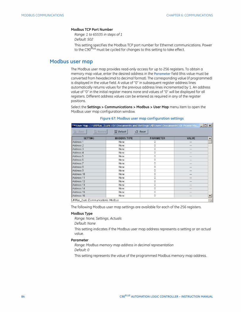
84 C90PLUS AUTOMATION LOGIC CONTROLLER – INSTRUCTION MANUAL
MODBUS COMMUNICATIONS CHAPTER 6: COMMUNICATIONS
Modbus TCP Port NumberRange: 1 to 65535 in steps of 1Default: 502
This setting specifies the Modbus TCP port number for Ethernet communications. Power to the C90Plus must be cycled for changes to this setting to take effect.
Modbus user mapThe Modbus user map provides read-only access for up to 256 registers. To obtain a memory map value, enter the desired address in the Parameter field (this value must be converted from hexadecimal to decimal format). The corresponding value (if programmed) is displayed in the value field. A value of “0” in subsequent register address lines automatically returns values for the previous address lines incremented by 1. An address value of “0” in the initial register means none and values of “0” will be displayed for all registers. Different address values can be entered as required in any of the register positions.
Select the Settings > Communications > Modbus > User Map menu item to open the Modbus user map configuration window.
Figure 67: Modbus user map configuration settings
The following Modbus user map settings are available for each of the 256 registers.
Modbus TypeRange: None, Settings, ActualsDefault: None
This setting indicates if the Modbus user map address represents a setting or an actual value.
ParameterRange: Modbus memory map address in decimal representationDefault: 0
This setting represents the value of the programmed Modbus memory map address.
CHAPTER 6: COMMUNICATIONS DNP COMMUNICATIONS
C90PLUS AUTOMATION LOGIC CONTROLLER – INSTRUCTION MANUAL 85
DNP communicationsThe DNP protocol allows for the optimization of control and data acquisition between the equipment in the substation and the central control center. The protocol is scalable; that is, it is designed to be compatible with the latest high speed LAN technology yet still be implemented over slower speed serial links.
The DNP protocol improves upon many master-slave protocols by improving overall communication performance requirements and provides time-stamping with millisecond accuracy.
See the C90Plus Communications Guide for details on the DNP protocol.
DNP protocolThe DNP server can simultaneously support one client over serial RS485 and two clients over Ethernet. Level 3 is supported for parsing requests and generating responses. It is capable of reporting any indication or measurement and operating any output present in the device. Both direct-operate and select-before-operate modes of control are supported. Three user-configurable input and output maps are implemented.
Select the Settings > Communications > DNP > Protocol menu item to open the DNP protocol configuration window.
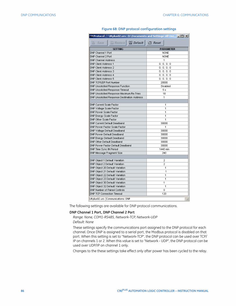
86 C90PLUS AUTOMATION LOGIC CONTROLLER – INSTRUCTION MANUAL
DNP COMMUNICATIONS CHAPTER 6: COMMUNICATIONS
Figure 68: DNP protocol configuration settings
The following settings are available for DNP protocol communications.
DNP Channel 1 Port, DNP Channel 2 PortRange: None, COM1-RS485, Network-TCP, Network-UDPDefault: None
These settings specify the communications port assigned to the DNP protocol for each channel. Once DNP is assigned to a serial port, the Modbus protocol is disabled on that port. When this setting is set to “Network-TCP”, the DNP protocol can be used over TCP/IP on channels 1 or 2. When this value is set to “Network - UDP”, the DNP protocol can be used over UDP/IP on channel 1 only.
Changes to the these settings take effect only after power has been cycled to the relay.
CHAPTER 6: COMMUNICATIONS DNP COMMUNICATIONS
C90PLUS AUTOMATION LOGIC CONTROLLER – INSTRUCTION MANUAL 87
DNP Channel AddressRange: 0 to 65519 in steps of 1Default: 1
This setting specifies the DNP slave address. This number identifies the C90Plus on a DNP communications link. Each DNP slave should be assigned a unique address.
DNP Client Address 1 through DNP Client Address 5Range: any standard IP addressDefault: 0.0.0.0
These settings force the C90Plus to respond to a maximum of five specific DNP masters.
DNP TCP/UDP Port NumberRange: 1 to 65535 in steps of 1Default: 20000
This setting specifies the TCP/UDP port used for DNP communications.
DNP Unsolicited Response FunctionRange: Enabled, DisabledDefault: Disabled
Program this setting to “Disabled” for RS485 applications, since there is no collision avoidance mechanism.
DNP Unsolicited Response TimeoutRange: 0 to 60 seconds in steps of 1Default: 5 seconds
This setting specifies how long the C90Plus waits for a DNP master to confirm an unsolicited response.
DNP Unsolicited Response Maximum Re-TriesRange: 1 to 255 in steps of 1Default: 10
This setting specifies the number of times the C90Plus retransmits an unsolicited response without receiving confirmation from the master. A value of “255” allows infinite re-tries.
DNP Unsolicited Response Destination AddressRange: 0 to 65519 in steps of 1Default: 1
This setting specifies the DNP address to which all unsolicited responses are sent. The IP address to which unsolicited responses are sent is determined by the C90Plus from the current TCP connection or the most recent UDP message.
DNP Current Scale Factor, DNP Voltage Scale Factor, DNP Power Scale Factor, DNP Power Factor Scale Factor, DNP Energy Scale Factor, DNP Other Scale Factor
Range: 0.001, 0.01. 0.1, 1, 10, 100, 1000, 10000, 100000Default: 1
These settings scale the analog input current values. For example, if the DNP Current Scale Factor is “10”, all DNP analog input points that represent currents will be returned with values 10 times smaller (for example, a value of 700 amps on the C90Plus will be returned as 70). Likewise, if the DNP Voltage Scale Factor is “0.01”, all DNP analog input points that represent voltages will be returned with values 100 times larger (for example, a value of 17 volts on the C90Plus will be returned as 1700).
These settings are useful when analog input values must be adjusted to fit within certain ranges in DNP masters.

88 C90PLUS AUTOMATION LOGIC CONTROLLER – INSTRUCTION MANUAL
DNP COMMUNICATIONS CHAPTER 6: COMMUNICATIONS
DNP Current Default Deadband, DNP Voltage Default Deadband, DNP Power Default Deadband, DNP Power Factor Default Deadband, DNP Energy Default Deadband, DNP Other Default Deadband
Range: 0 to 65535 in steps of 1Default: 30000
These settings determine when to trigger unsolicited responses containing analog Input data. These settings group the C90Plus analog input data into types: current, voltage, power, energy, and other. Each setting represents the default deadband value for all analog input points of that type. For example, to trigger unsolicited responses from the C90Plus when any current values change by 15 amps, the DNP Current Default Deadband setting should be set to “15”.
These settings are the deadband default values. DNP object 34 points can be used to change deadband values from the default for each individual DNP analog input point. Whenever power is removed and re-applied to the C90Plus, the default deadbands will be in effect.
DNP Time Sync IIN PeriodRange: 1 to 10080 minutes in steps of 1Default: 1440 minutes
This setting determines how often the Need Time Internal Indication (IIN) bit is set by the C90Plus. Changing this time allows the DNP master to send time synchronization commands more or less often, as required.
DNP Message Fragment SizeRange: 30 to 2048 in steps of 1Default: 240
This setting determines the size, in bytes, at which message fragmentation occurs. Large fragment sizes allow for more efficient throughput; smaller fragment sizes cause more application layer confirmations to be necessary which can provide for more robust data transfer over noisy communication channels.
DNP Object 1 Variation, DNP Object 2 Variation, DNP Object 20 Variation, DNP Object 21 Variation, DNP Object 22 Variation, DNP Object 23 Variation, DNP Object 30 Variation, DNP Object 32 Variation
Range: 1, 2 (object 1); 1, 2, 3 (object 2), 1, 2, 5, 6 (objects 20, 22, and 23); 1, 2, 9, 10 (object 21); 1, 2, 3, 4, 5 (object 30); 1, 2, 3, 4, 5, 7 (object 32)Default 1 (objects 2, 20, 21, 22, 23, 30, and 32); 2 (object 1)
These settings allow the user to select the DNP default variation number for object types 1, 2, 20, 21, 22, 23, 30, and 32. The default variation refers to the variation response when variation 0 is requested or in class 0, 1, 2, or 3 scans.
DNP Number of Paired ControlsRange: 0 to 32 in steps of 1Default: 0
The DNP binary outputs typically map one-to-one to IED data points. That is, each DNP binary output controls a single physical or virtual control point in an IED. In the C90Plus, DNP binary outputs are mapped to protection and/or automation virtual inputs.
Mapping is updated in the web page browser. Use this DNP Points Lists web page to verify the DNP configuration.
Some legacy DNP implementations use a mapping of one DNP binary output to two physical or virtual control points to support the concept of trip/close (for circuit breakers) or raise/lower (for tap changers) using a single control point. That is, the DNP master can operate a single point for both trip and close, or raise and lower, operations. The C90Plus can be configured to support paired control points, with each paired control point operating two virtual inputs (protection or automation). This setting allows
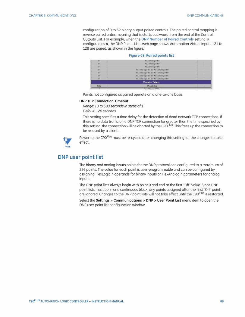
CHAPTER 6: COMMUNICATIONS DNP COMMUNICATIONS
C90PLUS AUTOMATION LOGIC CONTROLLER – INSTRUCTION MANUAL 89
configuration of 0 to 32 binary output paired controls. The paired control mapping is reverse paired order, meaning that is starts backward from the end of the Control Outputs List. For example, when the DNP Number of Paired Controls setting is configured as 4, the DNP Points Lists web page shows Automation Virtual Inputs 121 to 128 are paired, as shown in the figure.
Figure 69: Paired points list
Points not configured as paired operate on a one-to-one basis.
DNP TCP Connection TimeoutRange: 10 to 300 seconds in steps of 1Default: 120 seconds
This setting specifies a time delay for the detection of dead network TCP connections. If there is no data traffic on a DNP TCP connection for greater than the time specified by this setting, the connection will be aborted by the C90Plus. This frees up the connection to be re-used by a client.
NOTE
NOTE: Power to the C90Plus must be re-cycled after changing this setting for the changes to take effect.
DNP user point listThe binary and analog inputs points for the DNP protocol can configured to a maximum of 256 points. The value for each point is user-programmable and can be configured by assigning FlexLogic™ operands for binary inputs or FlexAnalog™ parameters for analog inputs.
The DNP point lists always begin with point 0 and end at the first “Off” value. Since DNP point lists must be in one continuous block, any points assigned after the first “Off” point are ignored. Changes to the DNP point lists will not take effect until the C90Plus is restarted.
Select the Settings > Communications > DNP > User Point List menu item to open the DNP user point list configuration window.
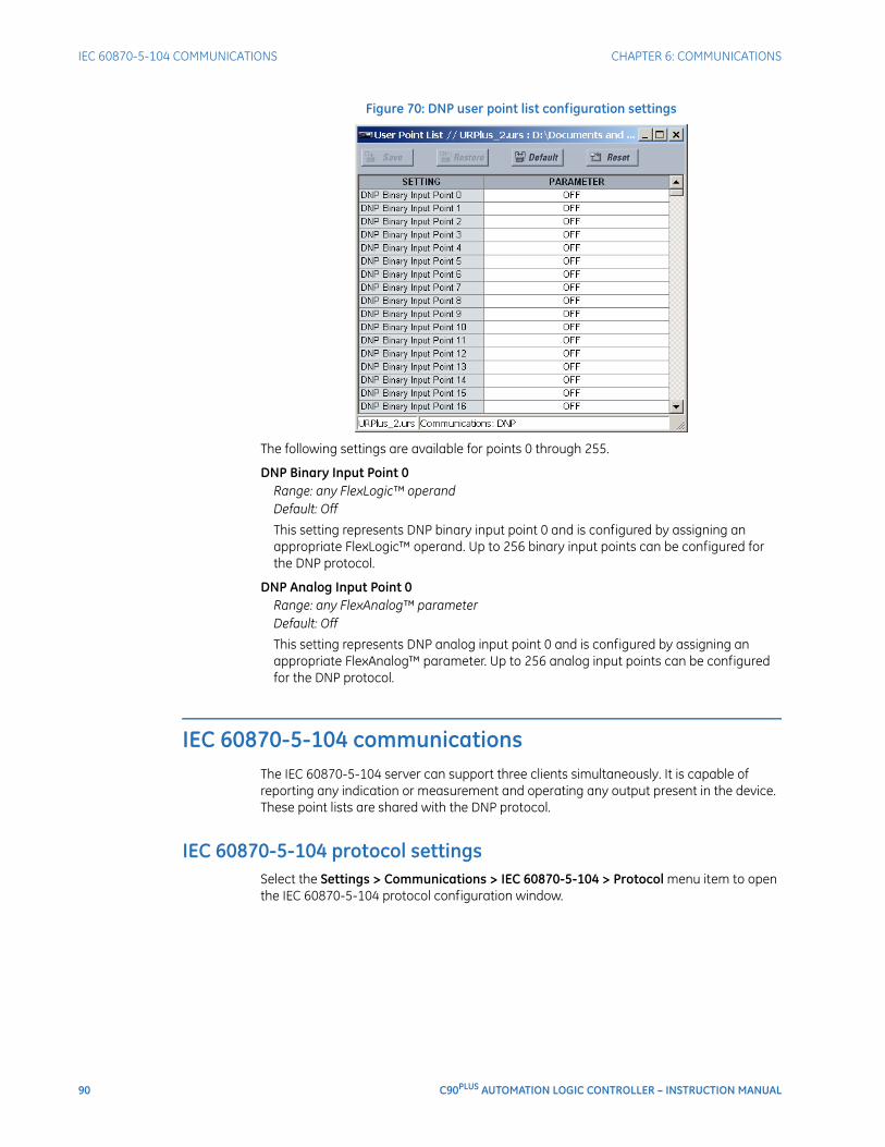
90 C90PLUS AUTOMATION LOGIC CONTROLLER – INSTRUCTION MANUAL
IEC 60870-5-104 COMMUNICATIONS CHAPTER 6: COMMUNICATIONS
Figure 70: DNP user point list configuration settings
The following settings are available for points 0 through 255.
DNP Binary Input Point 0Range: any FlexLogic™ operandDefault: Off
This setting represents DNP binary input point 0 and is configured by assigning an appropriate FlexLogic™ operand. Up to 256 binary input points can be configured for the DNP protocol.
DNP Analog Input Point 0Range: any FlexAnalog™ parameterDefault: Off
This setting represents DNP analog input point 0 and is configured by assigning an appropriate FlexAnalog™ parameter. Up to 256 analog input points can be configured for the DNP protocol.
IEC 60870-5-104 communicationsThe IEC 60870-5-104 server can support three clients simultaneously. It is capable of reporting any indication or measurement and operating any output present in the device. These point lists are shared with the DNP protocol.
IEC 60870-5-104 protocol settingsSelect the Settings > Communications > IEC 60870-5-104 > Protocol menu item to open the IEC 60870-5-104 protocol configuration window.
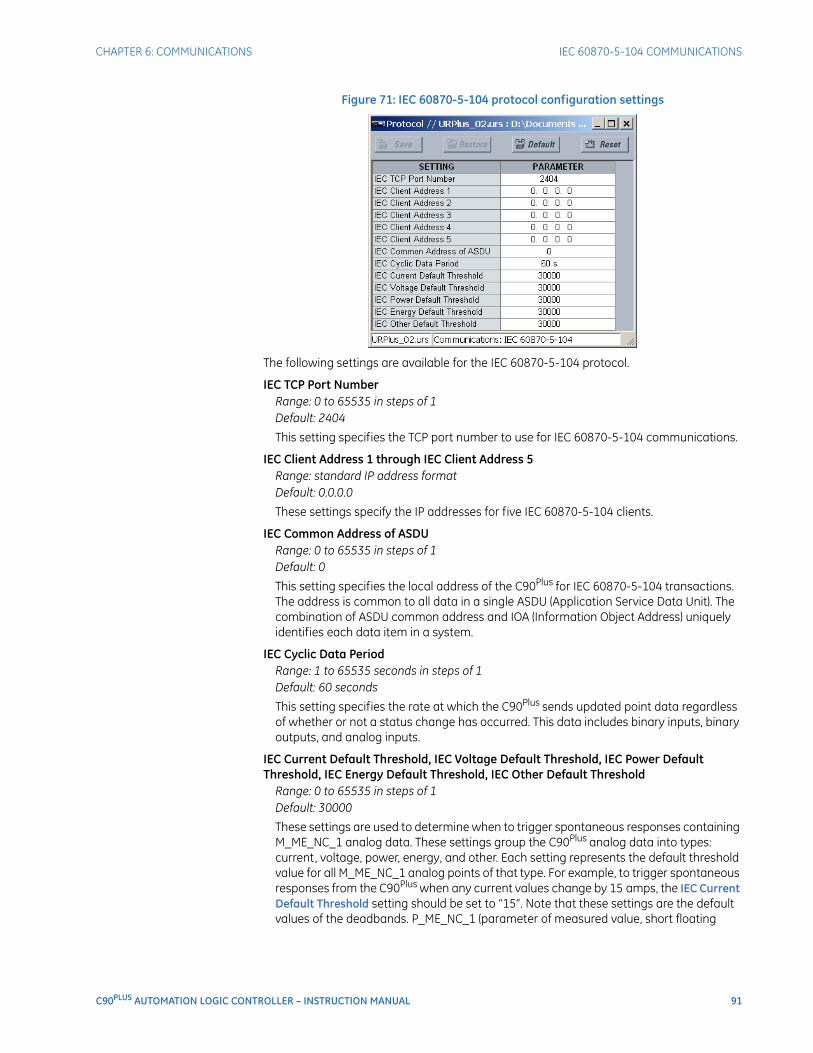
CHAPTER 6: COMMUNICATIONS IEC 60870-5-104 COMMUNICATIONS
C90PLUS AUTOMATION LOGIC CONTROLLER – INSTRUCTION MANUAL 91
Figure 71: IEC 60870-5-104 protocol configuration settings
The following settings are available for the IEC 60870-5-104 protocol.
IEC TCP Port NumberRange: 0 to 65535 in steps of 1Default: 2404
This setting specifies the TCP port number to use for IEC 60870-5-104 communications.
IEC Client Address 1 through IEC Client Address 5Range: standard IP address formatDefault: 0.0.0.0
These settings specify the IP addresses for five IEC 60870-5-104 clients.
IEC Common Address of ASDURange: 0 to 65535 in steps of 1Default: 0
This setting specifies the local address of the C90Plus for IEC 60870-5-104 transactions. The address is common to all data in a single ASDU (Application Service Data Unit). The combination of ASDU common address and IOA (Information Object Address) uniquely identifies each data item in a system.
IEC Cyclic Data PeriodRange: 1 to 65535 seconds in steps of 1Default: 60 seconds
This setting specifies the rate at which the C90Plus sends updated point data regardless of whether or not a status change has occurred. This data includes binary inputs, binary outputs, and analog inputs.
IEC Current Default Threshold, IEC Voltage Default Threshold, IEC Power Default Threshold, IEC Energy Default Threshold, IEC Other Default Threshold
Range: 0 to 65535 in steps of 1Default: 30000
These settings are used to determine when to trigger spontaneous responses containing M_ME_NC_1 analog data. These settings group the C90Plus analog data into types: current, voltage, power, energy, and other. Each setting represents the default threshold value for all M_ME_NC_1 analog points of that type. For example, to trigger spontaneous responses from the C90Plus when any current values change by 15 amps, the IEC Current Default Threshold setting should be set to “15”. Note that these settings are the default values of the deadbands. P_ME_NC_1 (parameter of measured value, short floating
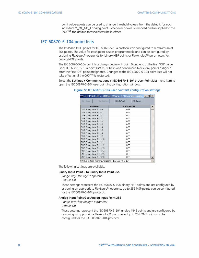
92 C90PLUS AUTOMATION LOGIC CONTROLLER – INSTRUCTION MANUAL
IEC 60870-5-104 COMMUNICATIONS CHAPTER 6: COMMUNICATIONS
point value) points can be used to change threshold values, from the default, for each individual M_ME_NC_1 analog point. Whenever power is removed and re-applied to the C90Plus, the default thresholds will be in effect.
IEC 60870-5-104 point listsThe MSP and MME points for IEC 60870-5-104 protocol can configured to a maximum of 256 points. The value for each point is user-programmable and can be configured by assigning FlexLogic™ operands for binary MSP points or FlexAnalog™ parameters for analog MME points.
The IEC 60870-5-104 point lists always begin with point 0 and end at the first “Off” value. Since IEC 60870-5-104 point lists must be in one continuous block, any points assigned after the first “Off” point are ignored. Changes to the IEC 60870-5-104 point lists will not take effect until the C90Plus is restarted.
Select the Settings > Communications > IEC 60870-5-104 > User Point List menu item to open the IEC 60870-5-104 user point list configuration window.
Figure 72: IEC 60870-5-104 user point list configuration settings
The following settings are available.
Binary Input Point 0 to Binary Input Point 255Range: any FlexLogic™ operandDefault: Off
These settings represent the IEC 60870-5-104 binary MSP points and are configured by assigning an appropriate FlexLogic™ operand. Up to 256 MSP points can be configured for the IEC 60870-5-104 protocol.
Analog Input Point 0 to Analog Input Point 255Range: any FlexAnalog™ parameterDefault: Off
These settings represent the IEC 60870-5-104 analog MME points and are configured by assigning an appropriate FlexAnalog™ parameter. Up to 256 MME points can be configured for the IEC 60870-5-104 protocol.
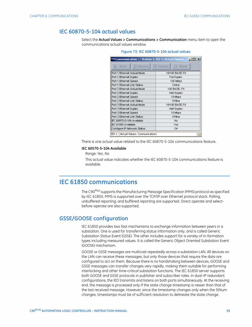
CHAPTER 6: COMMUNICATIONS IEC 61850 COMMUNICATIONS
C90PLUS AUTOMATION LOGIC CONTROLLER – INSTRUCTION MANUAL 93
IEC 60870-5-104 actual valuesSelect the Actual Values > Communications > Communication menu item to open the communications actual values window.
Figure 73: IEC 60870-5-104 actual values
There is one actual value related to the IEC 60870-5-104 communications feature.
IEC 60570-5-104 AvailableRange: Yes, No
This actual value indicates whether the IEC 60870-5-104 communications feature is available.
IEC 61850 communicationsThe C90Plus supports the Manufacturing Message Specification (MMS) protocol as specified by IEC 61850. MMS is supported over the TCP/IP over Ethernet protocol stack. Polling, unbuffered reporting, and buffered reporting are supported. Direct operate and select-before-operate are also supported.
GSSE/GOOSE configurationIEC 61850 provides two fast mechanisms to exchange information between peers in a substation. One is used for transferring status information only, and is called Generic Substation Status Event (GSSE). The other includes support for a variety of in-formation types including measured values. It is called the Generic Object Oriented Substation Event (GOOSE) mechanism.
GOOSE or GSSE messages are multicast repeatedly across a substation LAN. All devices on the LAN can receive these messages, but only those devices that require the data are configured to act on them. Because there is no handshaking between devices, GOOSE and GSSE messages can transfer changes very rapidly, making them suitable for performing interlocking and other time-critical substation functions. The IEC 61850 server supports both GOOSE and GSSE protocols in publisher and subscriber roles. In dual-IP redundant configurations, the IED transmits and listens on both ports simultaneously. At the receiving end, the message is processed only if the state change timestamp is newer than that of the last received message. However, since the timestamp changes only when the StNum changes, timestamps must be of sufficient resolution to delineate the state change.
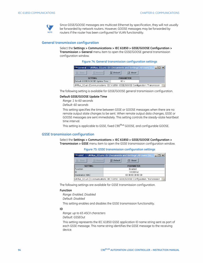
94 C90PLUS AUTOMATION LOGIC CONTROLLER – INSTRUCTION MANUAL
IEC 61850 COMMUNICATIONS CHAPTER 6: COMMUNICATIONS
NOTE
NOTE: Since GSSE/GOOSE messages are multicast Ethernet by specification, they will not usually be forwarded by network routers. However, GOOSE messages may be forwarded by routers if the router has been configured for VLAN functionality.
General transmission configurationSelect the Settings > Communications > IEC 61850 > GSSE/GOOSE Configuration > Transmission > General menu item to open the GSSE/GOOSE general transmission configuration window.
Figure 74: General transmission configuration settings
The following setting is available for GSSE/GOOSE general transmission configuration.
Default GSSE/GOOSE Update TimeRange: 1 to 60 secondsDefault: 60 seconds
This setting specifies the time between GSSE or GOOSE messages when there are no remote output state changes to be sent. When remote output data changes, GSSE or GOOSE messages are sent immediately. This setting controls the steady-state heartbeat time interval.
This setting is applicable to GSSE, fixed C90Plus GOOSE, and configurable GOOSE.
GSSE transmission configurationSelect the Settings > Communications > IEC 61850 > GSSE/GOOSE Configuration > Transmission > GSSE menu item to open the GSSE transmission configuration window.
Figure 75: GSSE transmission configuration settings
The following settings are available for GSSE transmission configuration.
FunctionRange: Enabled, DisabledDefault: Disabled
This setting enables and disables the GSSE transmission functionality.
IDRange: up to 65 ASCII charactersDefault: GSSEOut
This setting represents the IEC 61850 GSSE application ID name string sent as part of each GSSE message. This name string identifies the GSSE message to the receiving device.
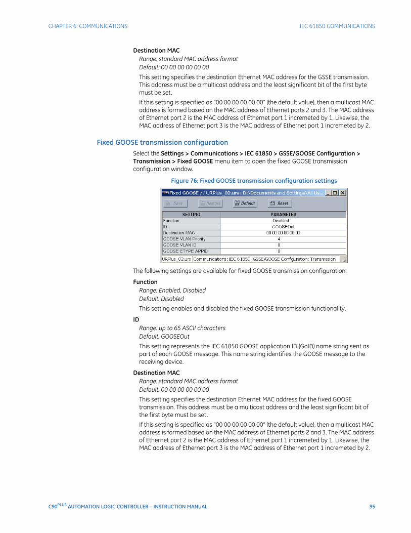
CHAPTER 6: COMMUNICATIONS IEC 61850 COMMUNICATIONS
C90PLUS AUTOMATION LOGIC CONTROLLER – INSTRUCTION MANUAL 95
Destination MACRange: standard MAC address formatDefault: 00 00 00 00 00 00
This setting specifies the destination Ethernet MAC address for the GSSE transmission. This address must be a multicast address and the least significant bit of the first byte must be set.
If this setting is specified as “00 00 00 00 00 00” (the default value), then a multicast MAC address is formed based on the MAC address of Ethernet ports 2 and 3. The MAC address of Ethernet port 2 is the MAC address of Ethernet port 1 incremeted by 1. Likewise, the MAC address of Ethernet port 3 is the MAC address of Ethernet port 1 incremeted by 2.
Fixed GOOSE transmission configurationSelect the Settings > Communications > IEC 61850 > GSSE/GOOSE Configuration > Transmission > Fixed GOOSE menu item to open the fixed GOOSE transmission configuration window.
Figure 76: Fixed GOOSE transmission configuration settings
The following settings are available for fixed GOOSE transmission configuration.
FunctionRange: Enabled, DisabledDefault: Disabled
This setting enables and disabled the fixed GOOSE transmission functionality.
IDRange: up to 65 ASCII charactersDefault: GOOSEOut
This setting represents the IEC 61850 GOOSE application ID (GoID) name string sent as part of each GOOSE message. This name string identifies the GOOSE message to the receiving device.
Destination MACRange: standard MAC address formatDefault: 00 00 00 00 00 00
This setting specifies the destination Ethernet MAC address for the fixed GOOSE transmission. This address must be a multicast address and the least significant bit of the first byte must be set.
If this setting is specified as “00 00 00 00 00 00” (the default value), then a multicast MAC address is formed based on the MAC address of Ethernet ports 2 and 3. The MAC address of Ethernet port 2 is the MAC address of Ethernet port 1 incremeted by 1. Likewise, the MAC address of Ethernet port 3 is the MAC address of Ethernet port 1 incremeted by 2.
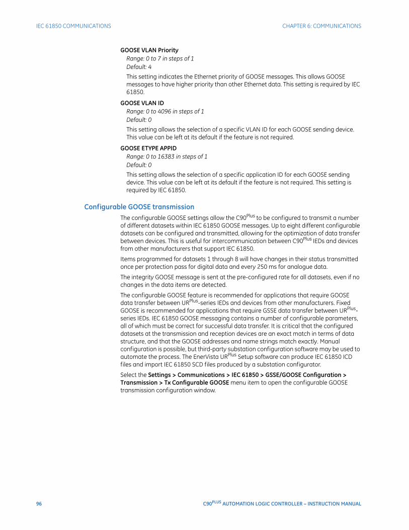
96 C90PLUS AUTOMATION LOGIC CONTROLLER – INSTRUCTION MANUAL
IEC 61850 COMMUNICATIONS CHAPTER 6: COMMUNICATIONS
GOOSE VLAN PriorityRange: 0 to 7 in steps of 1Default: 4
This setting indicates the Ethernet priority of GOOSE messages. This allows GOOSE messages to have higher priority than other Ethernet data. This setting is required by IEC 61850.
GOOSE VLAN IDRange: 0 to 4096 in steps of 1Default: 0
This setting allows the selection of a specific VLAN ID for each GOOSE sending device. This value can be left at its default if the feature is not required.
GOOSE ETYPE APPIDRange: 0 to 16383 in steps of 1Default: 0
This setting allows the selection of a specific application ID for each GOOSE sending device. This value can be left at its default if the feature is not required. This setting is required by IEC 61850.
Configurable GOOSE transmissionThe configurable GOOSE settings allow the C90Plus to be configured to transmit a number of different datasets within IEC 61850 GOOSE messages. Up to eight different configurable datasets can be configured and transmitted, allowing for the optimization of data transfer between devices. This is useful for intercommunication between C90Plus IEDs and devices from other manufacturers that support IEC 61850.
Items programmed for datasets 1 through 8 will have changes in their status transmitted once per protection pass for digital data and every 250 ms for analogue data.
The integrity GOOSE message is sent at the pre-configured rate for all datasets, even if no changes in the data items are detected.
The configurable GOOSE feature is recommended for applications that require GOOSE data transfer between URPlus-series IEDs and devices from other manufacturers. Fixed GOOSE is recommended for applications that require GSSE data transfer between URPlus-series IEDs. IEC 61850 GOOSE messaging contains a number of configurable parameters, all of which must be correct for successful data transfer. It is critical that the configured datasets at the transmission and reception devices are an exact match in terms of data structure, and that the GOOSE addresses and name strings match exactly. Manual configuration is possible, but third-party substation configuration software may be used to automate the process. The EnerVista URPlus Setup software can produce IEC 61850 ICD files and import IEC 61850 SCD files produced by a substation configurator.
Select the Settings > Communications > IEC 61850 > GSSE/GOOSE Configuration > Transmission > Tx Configurable GOOSE menu item to open the configurable GOOSE transmission configuration window.
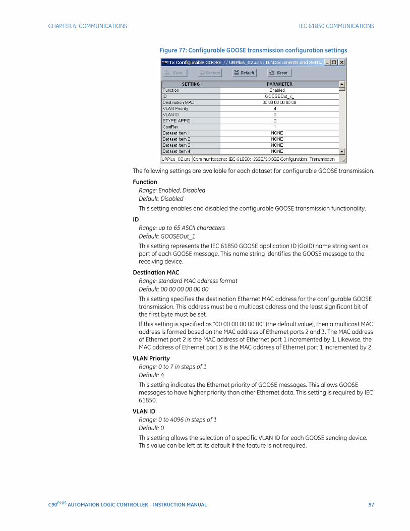
CHAPTER 6: COMMUNICATIONS IEC 61850 COMMUNICATIONS
C90PLUS AUTOMATION LOGIC CONTROLLER – INSTRUCTION MANUAL 97
Figure 77: Configurable GOOSE transmission configuration settings
The following settings are available for each dataset for configurable GOOSE transmission.
FunctionRange: Enabled, DisabledDefault: Disabled
This setting enables and disabled the configurable GOOSE transmission functionality.
IDRange: up to 65 ASCII charactersDefault: GOOSEOut_1
This setting represents the IEC 61850 GOOSE application ID (GoID) name string sent as part of each GOOSE message. This name string identifies the GOOSE message to the receiving device.
Destination MACRange: standard MAC address formatDefault: 00 00 00 00 00 00
This setting specifies the destination Ethernet MAC address for the configurable GOOSE transmission. This address must be a multicast address and the least significant bit of the first byte must be set.
If this setting is specified as “00 00 00 00 00 00” (the default value), then a multicast MAC address is formed based on the MAC address of Ethernet ports 2 and 3. The MAC address of Ethernet port 2 is the MAC address of Ethernet port 1 incremented by 1. Likewise, the MAC address of Ethernet port 3 is the MAC address of Ethernet port 1 incremented by 2.
VLAN PriorityRange: 0 to 7 in steps of 1Default: 4
This setting indicates the Ethernet priority of GOOSE messages. This allows GOOSE messages to have higher priority than other Ethernet data. This setting is required by IEC 61850.
VLAN IDRange: 0 to 4096 in steps of 1Default: 0
This setting allows the selection of a specific VLAN ID for each GOOSE sending device. This value can be left at its default if the feature is not required.
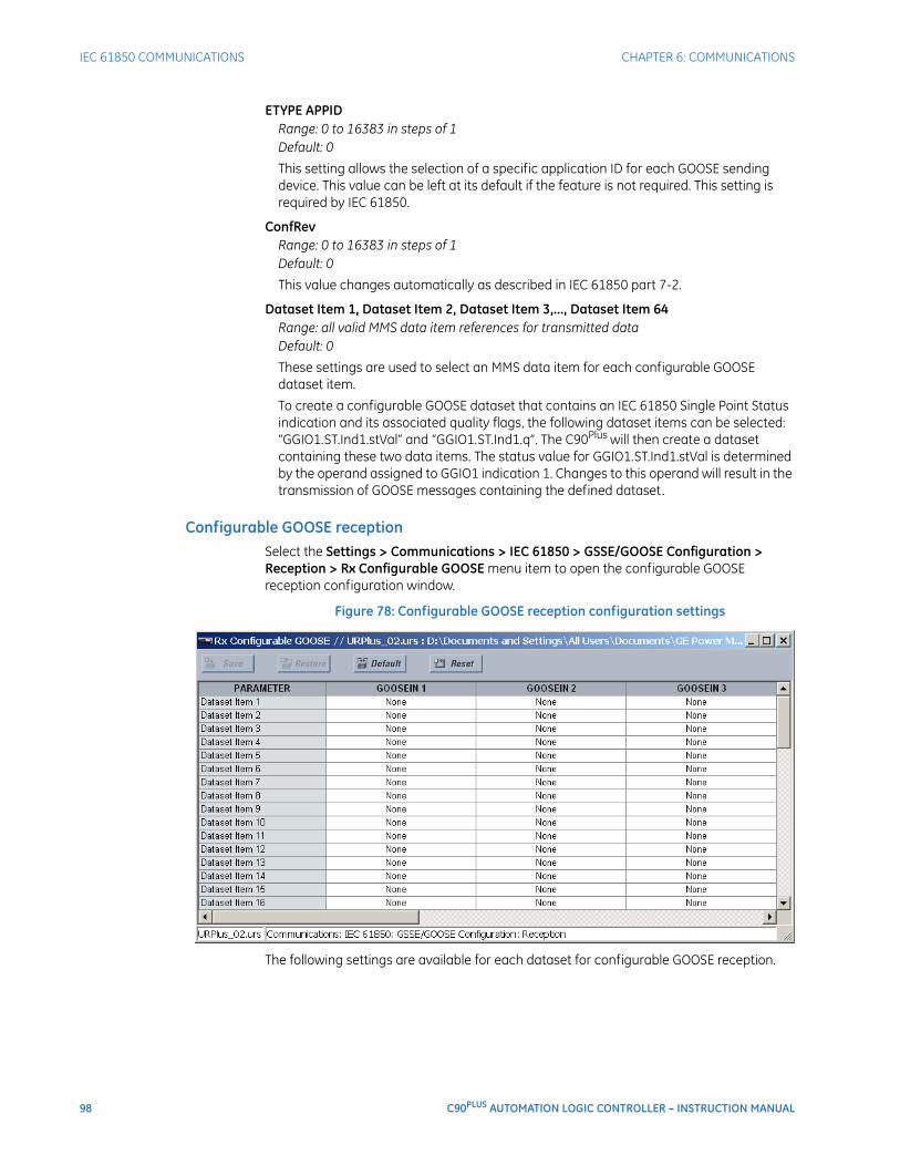
98 C90PLUS AUTOMATION LOGIC CONTROLLER – INSTRUCTION MANUAL
IEC 61850 COMMUNICATIONS CHAPTER 6: COMMUNICATIONS
ETYPE APPIDRange: 0 to 16383 in steps of 1Default: 0
This setting allows the selection of a specific application ID for each GOOSE sending device. This value can be left at its default if the feature is not required. This setting is required by IEC 61850.
ConfRevRange: 0 to 16383 in steps of 1Default: 0
This value changes automatically as described in IEC 61850 part 7-2.
Dataset Item 1, Dataset Item 2, Dataset Item 3,..., Dataset Item 64Range: all valid MMS data item references for transmitted dataDefault: 0
These settings are used to select an MMS data item for each configurable GOOSE dataset item.
To create a configurable GOOSE dataset that contains an IEC 61850 Single Point Status indication and its associated quality flags, the following dataset items can be selected: “GGIO1.ST.Ind1.stVal” and “GGIO1.ST.Ind1.q”. The C90Plus will then create a dataset containing these two data items. The status value for GGIO1.ST.Ind1.stVal is determined by the operand assigned to GGIO1 indication 1. Changes to this operand will result in the transmission of GOOSE messages containing the defined dataset.
Configurable GOOSE receptionSelect the Settings > Communications > IEC 61850 > GSSE/GOOSE Configuration > Reception > Rx Configurable GOOSE menu item to open the configurable GOOSE reception configuration window.
Figure 78: Configurable GOOSE reception configuration settings
The following settings are available for each dataset for configurable GOOSE reception.

CHAPTER 6: COMMUNICATIONS IEC 61850 COMMUNICATIONS
C90PLUS AUTOMATION LOGIC CONTROLLER – INSTRUCTION MANUAL 99
Dataset Item 1, Dataset Item 2, Dataset Item 3,..., Dataset Item 64Range: all valid MMS data item references for transmitted dataDefault: 0
These settings are used to select an MMS data item for each configurable GOOSE dataset item.
Remote devicesRemote inputs and outputs provide a means of exchanging digital state information between Ethernet-connected devices. The IEC 61850 GSSE (Generic Substation State Event) and GOOSE (Generic Object Oriented Substation Event) standards are used for this purpose.
The sharing of digital point state information between GSSE/GOOSE equipped relays is essentially an extension to FlexLogic™, allowing for distributed FlexLogic™ by making operands available to and from devices on a common communications network. In addition to digital point states, GSSE/GOOSE messages identify the originator of the message and provide other information required by the communication specification. All devices listen to network messages and capture data only from messages that have originated in selected devices.
IEC 61850 GSSE messages are compatible with UCA GOOSE messages and contain a fixed set of digital points. IEC 61850 GOOSE messages can, in general, contain any configurable data items. When used by the remote inputs and outputs feature, IEC 61850 GOOSE messages contain the same data as GSSE messages.
Both GSSE and GOOSE messages are designed to be short, reliable, and have high priority. GOOSE messages have additional advantages over GSSE messages due to their support of VLAN (virtual LAN) and Ethernet priority tagging functionality. The GSSE message structure contains space for 128 bit pairs representing digital point state information. The IEC 61850 specification provides 32 DNA bit pairs that represent the state of two pre-defined events and 30 user-defined events. All remaining bit pairs are UserSt bit pairs, which are status bits representing user-definable events. The C90Plus implementation provides 32 of the 96 available UserSt bit pairs.
The IEC 61850 specification includes features that are used to cope with the loss of communication between transmitting and receiving devices. Each transmitting device will send a GSSE/GOOSE message upon a successful power-up, when the state of any included point changes, or after a specified interval (the default update time) if a change-of-state has not occurred. The transmitting device also sends a hold time which is the GSSE equivalent of “time to live” in IEC GOOSE messages.
Receiving devices are constantly monitoring the communications network for messages they require, as recognized by the identification of the originating device carried in the message. Messages received from remote devices include the message time allowed to live. The receiving relay sets a timer assigned to the originating device to this time interval, and if it has not received another message from this device at time-out, the remote device is declared to be non-communicating, so it will use the programmed default state for all points from that specific remote device. If a message is received from a remote device before the time allowed to live expires, all points for that device are updated to the states contained in the message and the hold timer is restarted. The status of a remote device, where “Offline” indicates non-communicating, can be displayed.
The C90Plus provides for 64 remote inputs and 64 remote outputs.
In a URPlus-series IED, the device ID that identifies the originator of the message is programmed in the IED Name setting.
Select the Settings > Communications > IEC 61850 > GSSE/GOOSE Configuration > Inputs/Outputs > Remote Devices menu item to open the remote devices configuration window.
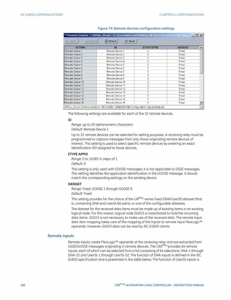
100 C90PLUS AUTOMATION LOGIC CONTROLLER – INSTRUCTION MANUAL
IEC 61850 COMMUNICATIONS CHAPTER 6: COMMUNICATIONS
Figure 79: Remote devices configuration settings
The following settings are available for each of the 32 remote devices.
IDRange: up to 20 alphanumeric charactersDefault: Remote Device 1
Up to 32 remote devices can be selected for setting purposes. A receiving relay must be programmed to capture messages from only those originating remote devices of interest. This setting is used to select specific remote devices by entering an exact identification (ID) assigned to those devices.
ETYPE APPIDRange: 0 to 16383 in steps of 1Default: 0
This setting is only used with GOOSE messages; it is not applicable to GSSE messages. This setting identifies the application identification in the GOOSE message. It should match the corresponding settings on the sending device.
DATASETRange: Fixed, GOOSE 1 through GOOSE 8Default: Fixed
This setting provides for the choice of the URPlus-series fixed (DNA/UserSt) dataset (that is, containing DNA and UserSt bit pairs), or one of the configurable datasets.
The dataset for the received data items must be made up of existing items in an existing logical node. For this reason, logical node GGIO3 is instantiated to hold the incoming data items. GGIO3 is not necessary to make use of the received data. The remote input data item mapping takes care of the mapping of the inputs to remote input FlexLogic™ operands. However, GGIO3 data can be read by IEC 61850 clients.
Remote inputsRemote inputs create FlexLogic™ operands at the receiving relay and are extracted from GSSE/GOOSE messages originating in remote devices. The C90Plus provides 64 remote inputs, each of which can be selected from a list consisting of 64 selections: DNA-1 through DNA-32 and UserSt-1 through UserSt-32. The function of DNA inputs is defined in the IEC 61850 specification and is presented in the table below. The function of UserSt inputs is
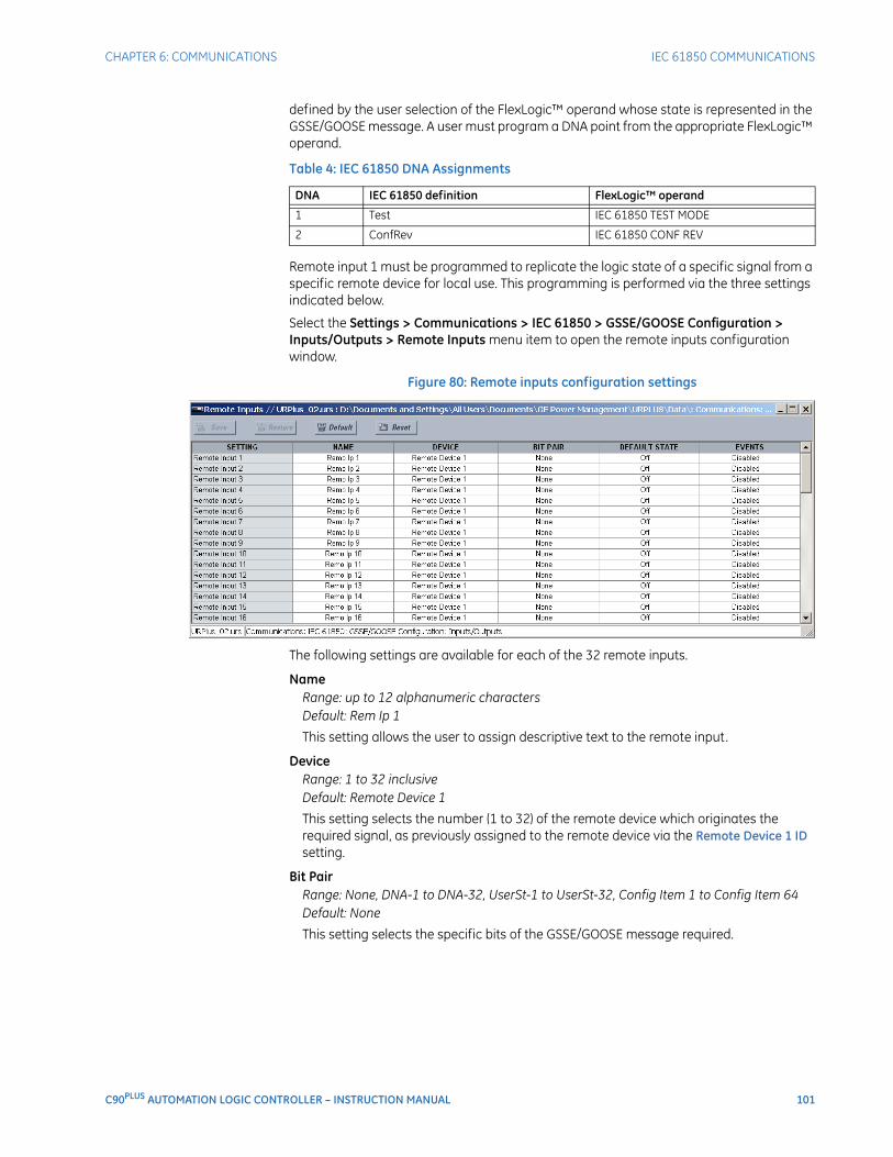
CHAPTER 6: COMMUNICATIONS IEC 61850 COMMUNICATIONS
C90PLUS AUTOMATION LOGIC CONTROLLER – INSTRUCTION MANUAL 101
defined by the user selection of the FlexLogic™ operand whose state is represented in the GSSE/GOOSE message. A user must program a DNA point from the appropriate FlexLogic™ operand.
Table 4: IEC 61850 DNA Assignments
Remote input 1 must be programmed to replicate the logic state of a specific signal from a specific remote device for local use. This programming is performed via the three settings indicated below.
Select the Settings > Communications > IEC 61850 > GSSE/GOOSE Configuration > Inputs/Outputs > Remote Inputs menu item to open the remote inputs configuration window.
Figure 80: Remote inputs configuration settings
The following settings are available for each of the 32 remote inputs.
NameRange: up to 12 alphanumeric charactersDefault: Rem Ip 1
This setting allows the user to assign descriptive text to the remote input.
DeviceRange: 1 to 32 inclusiveDefault: Remote Device 1
This setting selects the number (1 to 32) of the remote device which originates the required signal, as previously assigned to the remote device via the Remote Device 1 ID setting.
Bit PairRange: None, DNA-1 to DNA-32, UserSt-1 to UserSt-32, Config Item 1 to Config Item 64Default: None
This setting selects the specific bits of the GSSE/GOOSE message required.
DNA IEC 61850 definition FlexLogic™ operand
1 Test IEC 61850 TEST MODE
2 ConfRev IEC 61850 CONF REV

102 C90PLUS AUTOMATION LOGIC CONTROLLER – INSTRUCTION MANUAL
IEC 61850 COMMUNICATIONS CHAPTER 6: COMMUNICATIONS
Default StateRange: On, Off, Latest/On, Latest/OffDefault: Off
This setting selects the logic state for this point if the local relay has just completed startup or the remote device sending the point is declared to be non-communicating. The following choices are available.
– The “On” value defaults the input to logic 1.
– The “Off” value defaults the input to logic 0.
– The “Latest/On” value freezes the input in case of lost communications. If the latest state is not known, such as after relay power-up but before the first communication exchange, the input will default to logic 1. When communication resumes, the input becomes fully operational.
– The “Latest/Off” value freezes the input in case of lost communications. If the latest state is not known, such as after relay power-up but before the first communication exchange, the input will default to logic 0. When communication resumes, the input becomes fully operational.
EventsRange: Enabled, DisabledDefault: Disabled
This setting enables and disables the logging of remote input events in the sequence of events recorder.
Remote double-point status inputsRemote double-point status inputs are extracted from GOOSE messages originating in the remote device. The C90Plus provides 16 remote double-point status inputs. Each remote double-point status input must be programmed to replicate the logic state of a specific signal from a specific remote device for local use.
The configurable GOOSE dataset items must be changed to accept a double-point status item from a GOOSE dataset. Dataset items configured to receive any of “GGIO3.ST.IndPos1.stV” to “GGIO3.ST.IndPos16.stV” will accept double-point status information that will be decoded by the remote double-point status inputs configured to this dataset item.
Select the Settings > Communications > IEC 61850 > GSSE/GOOSE Configuration > Inputs/Outputs > Remote DPS Inputs menu item to open the remote double-point status inputs configuration window.
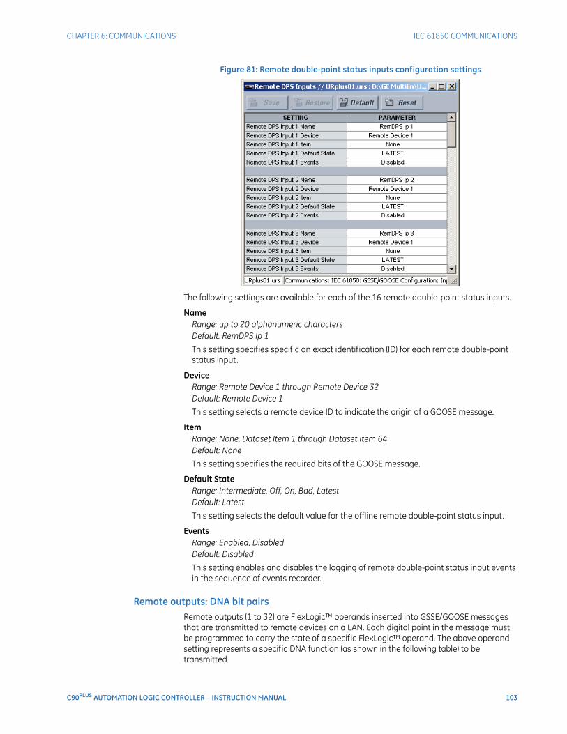
CHAPTER 6: COMMUNICATIONS IEC 61850 COMMUNICATIONS
C90PLUS AUTOMATION LOGIC CONTROLLER – INSTRUCTION MANUAL 103
Figure 81: Remote double-point status inputs configuration settings
The following settings are available for each of the 16 remote double-point status inputs.
NameRange: up to 20 alphanumeric charactersDefault: RemDPS Ip 1
This setting specifies specific an exact identification (ID) for each remote double-point status input.
DeviceRange: Remote Device 1 through Remote Device 32Default: Remote Device 1
This setting selects a remote device ID to indicate the origin of a GOOSE message.
ItemRange: None, Dataset Item 1 through Dataset Item 64Default: None
This setting specifies the required bits of the GOOSE message.
Default StateRange: Intermediate, Off, On, Bad, LatestDefault: Latest
This setting selects the default value for the offline remote double-point status input.
EventsRange: Enabled, DisabledDefault: Disabled
This setting enables and disables the logging of remote double-point status input events in the sequence of events recorder.
Remote outputs: DNA bit pairsRemote outputs (1 to 32) are FlexLogic™ operands inserted into GSSE/GOOSE messages that are transmitted to remote devices on a LAN. Each digital point in the message must be programmed to carry the state of a specific FlexLogic™ operand. The above operand setting represents a specific DNA function (as shown in the following table) to be transmitted.
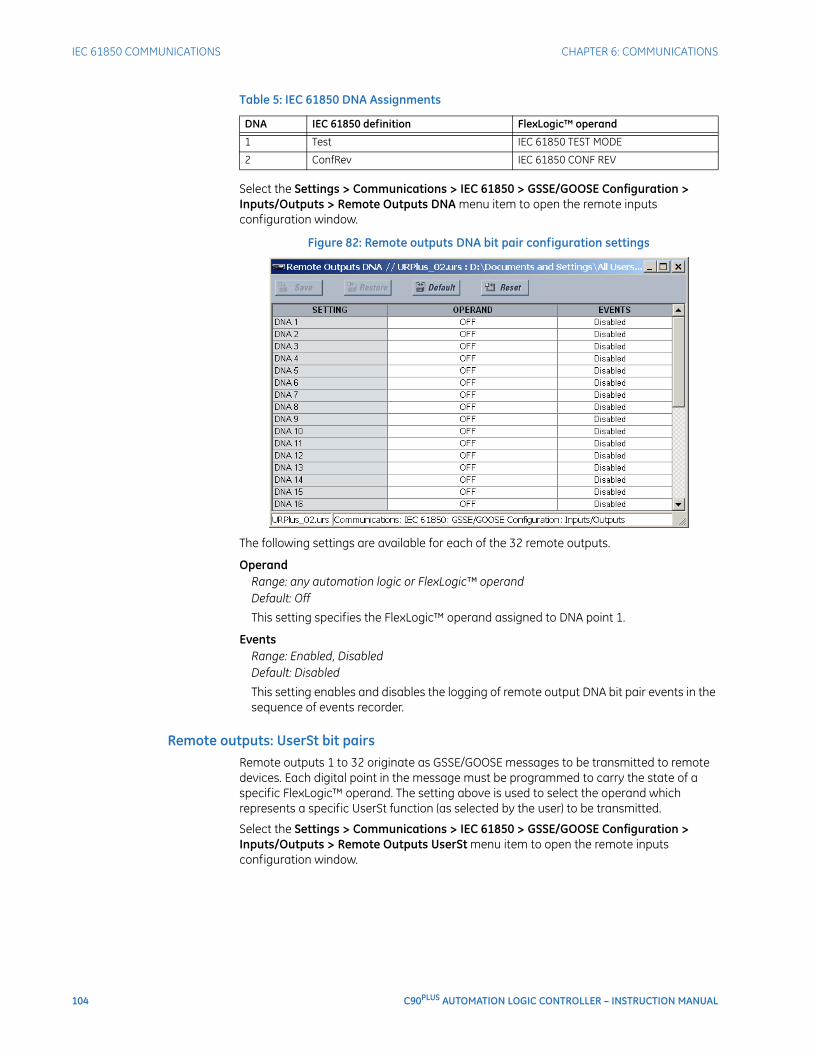
104 C90PLUS AUTOMATION LOGIC CONTROLLER – INSTRUCTION MANUAL
IEC 61850 COMMUNICATIONS CHAPTER 6: COMMUNICATIONS
Table 5: IEC 61850 DNA Assignments
Select the Settings > Communications > IEC 61850 > GSSE/GOOSE Configuration > Inputs/Outputs > Remote Outputs DNA menu item to open the remote inputs configuration window.
Figure 82: Remote outputs DNA bit pair configuration settings
The following settings are available for each of the 32 remote outputs.
OperandRange: any automation logic or FlexLogic™ operandDefault: Off
This setting specifies the FlexLogic™ operand assigned to DNA point 1.
EventsRange: Enabled, DisabledDefault: Disabled
This setting enables and disables the logging of remote output DNA bit pair events in the sequence of events recorder.
Remote outputs: UserSt bit pairsRemote outputs 1 to 32 originate as GSSE/GOOSE messages to be transmitted to remote devices. Each digital point in the message must be programmed to carry the state of a specific FlexLogic™ operand. The setting above is used to select the operand which represents a specific UserSt function (as selected by the user) to be transmitted.
Select the Settings > Communications > IEC 61850 > GSSE/GOOSE Configuration > Inputs/Outputs > Remote Outputs UserSt menu item to open the remote inputs configuration window.
DNA IEC 61850 definition FlexLogic™ operand
1 Test IEC 61850 TEST MODE
2 ConfRev IEC 61850 CONF REV
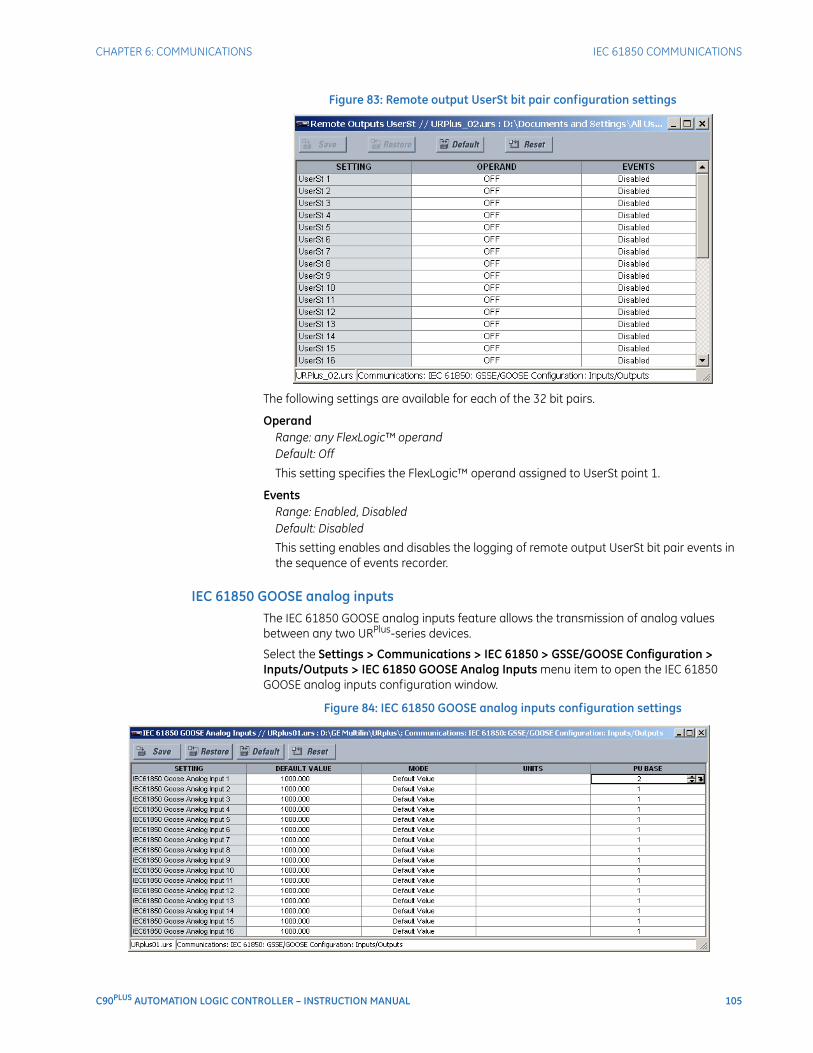
CHAPTER 6: COMMUNICATIONS IEC 61850 COMMUNICATIONS
C90PLUS AUTOMATION LOGIC CONTROLLER – INSTRUCTION MANUAL 105
Figure 83: Remote output UserSt bit pair configuration settings
The following settings are available for each of the 32 bit pairs.
OperandRange: any FlexLogic™ operandDefault: Off
This setting specifies the FlexLogic™ operand assigned to UserSt point 1.
EventsRange: Enabled, DisabledDefault: Disabled
This setting enables and disables the logging of remote output UserSt bit pair events in the sequence of events recorder.
IEC 61850 GOOSE analog inputsThe IEC 61850 GOOSE analog inputs feature allows the transmission of analog values between any two URPlus-series devices.
Select the Settings > Communications > IEC 61850 > GSSE/GOOSE Configuration > Inputs/Outputs > IEC 61850 GOOSE Analog Inputs menu item to open the IEC 61850 GOOSE analog inputs configuration window.
Figure 84: IEC 61850 GOOSE analog inputs configuration settings
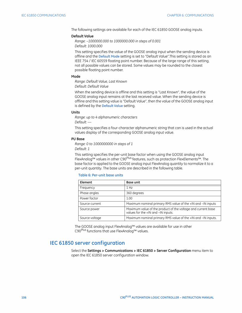
106 C90PLUS AUTOMATION LOGIC CONTROLLER – INSTRUCTION MANUAL
IEC 61850 COMMUNICATIONS CHAPTER 6: COMMUNICATIONS
The following settings are available for each of the IEC 61850 GOOSE analog inputs.
Default ValueRange: –1000000.000 to 1000000.000 in steps of 0.001Default: 1000.000
This setting specifies the value of the GOOSE analog input when the sending device is offline and the Default Mode setting is set to “Default Value”.This setting is stored as an IEEE 754 / IEC 60559 floating point number. Because of the large range of this setting, not all possible values can be stored. Some values may be rounded to the closest possible floating point number.
ModeRange: Default Value, Last KnownDefault: Default Value
When the sending device is offline and this setting is “Last Known”, the value of the GOOSE analog input remains at the last received value. When the sending device is offline and this setting value is “Default Value”, then the value of the GOOSE analog input is defined by the Default Value setting.
UnitsRange: up to 4 alphanumeric charactersDefault: ---
This setting specifies a four-character alphanumeric string that can is used in the actual values display of the corresponding GOOSE analog input value.
PU BaseRange: 0 to 1000000000 in steps of 1Default: 1
This setting specifies the per-unit base factor when using the GOOSE analog input FlexAnalog™ values in other C90Plus features, such as protection FlexElements™. The base factor is applied to the GOOSE analog input FlexAnalog quantity to normalize it to a per-unit quantity. The base units are described in the following table.
Table 6: Per-unit base units
The GOOSE analog input FlexAnalog™ values are available for use in other C90Plus functions that use FlexAnalog™ values.
IEC 61850 server configurationSelect the Settings > Communications > IEC 61850 > Server Configuration menu item to open the IEC 61850 server configuration window.
Element Base unit
Frequency 1 Hz
Phase angles 360 degrees
Power factor 1.00
Source current Maximum nominal primary RMS value of the +IN and –IN inputs
Source power Maximum value of the product of the voltage and current base values for the +IN and –IN inputs.
Source voltage Maximum nominal primary RMS value of the +IN and –IN inputs.
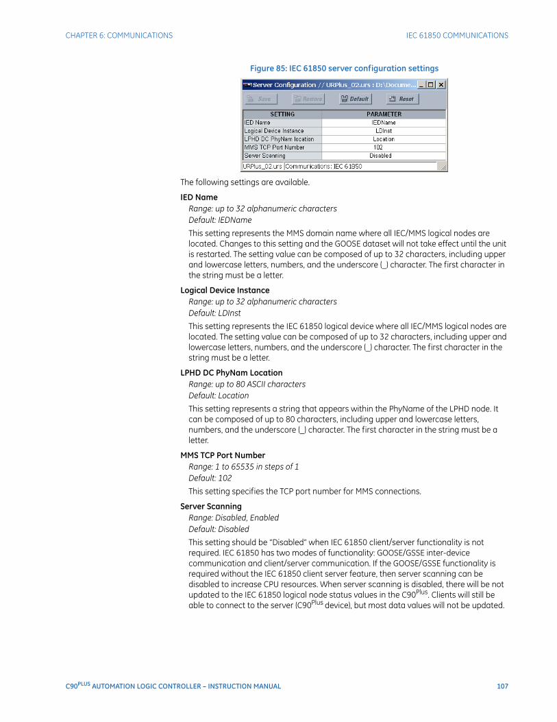
CHAPTER 6: COMMUNICATIONS IEC 61850 COMMUNICATIONS
C90PLUS AUTOMATION LOGIC CONTROLLER – INSTRUCTION MANUAL 107
Figure 85: IEC 61850 server configuration settings
The following settings are available.
IED NameRange: up to 32 alphanumeric charactersDefault: IEDName
This setting represents the MMS domain name where all IEC/MMS logical nodes are located. Changes to this setting and the GOOSE dataset will not take effect until the unit is restarted. The setting value can be composed of up to 32 characters, including upper and lowercase letters, numbers, and the underscore (_) character. The first character in the string must be a letter.
Logical Device InstanceRange: up to 32 alphanumeric charactersDefault: LDInst
This setting represents the IEC 61850 logical device where all IEC/MMS logical nodes are located. The setting value can be composed of up to 32 characters, including upper and lowercase letters, numbers, and the underscore (_) character. The first character in the string must be a letter.
LPHD DC PhyNam LocationRange: up to 80 ASCII charactersDefault: Location
This setting represents a string that appears within the PhyName of the LPHD node. It can be composed of up to 80 characters, including upper and lowercase letters, numbers, and the underscore (_) character. The first character in the string must be a letter.
MMS TCP Port NumberRange: 1 to 65535 in steps of 1Default: 102
This setting specifies the TCP port number for MMS connections.
Server ScanningRange: Disabled, EnabledDefault: Disabled
This setting should be “Disabled” when IEC 61850 client/server functionality is not required. IEC 61850 has two modes of functionality: GOOSE/GSSE inter-device communication and client/server communication. If the GOOSE/GSSE functionality is required without the IEC 61850 client server feature, then server scanning can be disabled to increase CPU resources. When server scanning is disabled, there will be not updated to the IEC 61850 logical node status values in the C90Plus. Clients will still be able to connect to the server (C90Plus device), but most data values will not be updated.
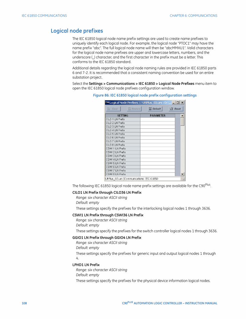
108 C90PLUS AUTOMATION LOGIC CONTROLLER – INSTRUCTION MANUAL
IEC 61850 COMMUNICATIONS CHAPTER 6: COMMUNICATIONS
Logical node prefixesThe IEC 61850 logical node name prefix settings are used to create name prefixes to uniquely identify each logical node. For example, the logical node “PTOC1” may have the name prefix “abc”. The full logical node name will then be “abcMMXU1”. Valid characters for the logical node name prefixes are upper and lowercase letters, numbers, and the underscore (_) character, and the first character in the prefix must be a letter. This conforms to the IEC 61850 standard.
Additional details regarding the logical node naming rules are provided in IEC 61850 parts 6 and 7-2. It is recommended that a consistent naming convention be used for an entire substation project.
Select the Settings > Communications > IEC 61850 > Logical Node Prefixes menu item to open the IEC 61850 logical node prefixes configuration window.
Figure 86: IEC 61850 logical node prefix configuration settings
The following IEC 61850 logical node name prefix settings are available for the C90Plus.
CILO1 LN Prefix through CILO36 LN PrefixRange: six character ASCII stringDefault: empty
These settings specify the prefixes for the interlocking logical nodes 1 through 3636.
CSWI1 LN Prefix through CSWI36 LN PrefixRange: six character ASCII stringDefault: empty
These settings specify the prefixes for the switch controller logical nodes 1 through 3636.
GGIO1 LN Prefix through GGIO4 LN PrefixRange: six character ASCII stringDefault: empty
These settings specify the prefixes for generic input and output logical nodes 1 through 4.
LPHD1 LN PrefixRange: six character ASCII stringDefault: empty
These settings specify the prefixes for the physical device information logical nodes.

CHAPTER 6: COMMUNICATIONS IEC 61850 COMMUNICATIONS
C90PLUS AUTOMATION LOGIC CONTROLLER – INSTRUCTION MANUAL 109
MMXU1 LN Prefix through MMXU4 LN PrefixRange: six character ASCII stringDefault: empty
These settings specify the prefixes for measured quantity logical nodes 1 through 4.
PFRC1 LN Prefix through PFRC4 LN PrefixRange: six character ASCII stringDefault: empty
These settings specify the prefixes for the frequency rate of change logical nodes 1 through 4.
PIOC1 LN Prefix through PIOC14 LN PrefixRange: six character ASCII stringDefault: empty
These settings specify the prefixes for instantaneous overcurrent logical nodes 1 through 14.
PTOC1 LN Prefix through PTOC18 LN PrefixRange: six character ASCII stringDefault: empty
These settings specify the prefixes for time overcurrent logical nodes 1 through 18.
PTOV1 LN Prefix through PTOV8 LN PrefixRange: six character ASCII stringDefault: empty
These settings specify the prefixes for overvoltage logical nodes 1 through 8.
PTRC1 LN Prefix through PTRC6 LN PrefixRange: six character ASCII stringDefault: empty
These settings specify the prefixes for the protection trip conditioning 1 through 6 logical nodes.
PTUF1 LN Prefix through PTUF10 LN PrefixRange: six character ASCII stringDefault: empty
These settings specify the prefixes for underfrequency load shedding logical nodes 1 through 10.
PTUV1 LN Prefix through PTUV10 LN PrefixRange: six character ASCII stringDefault: empty
These settings specify the prefixes for undervoltage logical nodes 1 through 1010.
RBRF1 LN Prefix, RBRF2 LN PrefixRange: six character ASCII stringDefault: empty
These settings specify the prefixes for breaker failure logical nodes 1 and 2.
RDIR1 LN Prefix, RDIR2 LN PrefixRange: six character ASCII stringDefault: empty
These settings specify the prefixes for the directional element logical nodes 1 and 2.
110 C90PLUS AUTOMATION LOGIC CONTROLLER – INSTRUCTION MANUAL
IEC 61850 COMMUNICATIONS CHAPTER 6: COMMUNICATIONS
RFLO1 LN PrefixRange: six character ASCII stringDefault: empty
This setting specifies the prefix for the fault locator logical node.
RREC1 LN PrefixRange: six character ASCII stringDefault: empty
This setting specifies the prefix for the autoreclose logical node.
RSYN1 LN Prefix, RSYN2 LN PrefixRange: six character ASCII stringDefault: empty
This setting specifies the prefix for the synchrocheck logical nodes 1 and 2.
XCBR1 LN Prefix through XCBR6 LN PrefixRange: six character ASCII stringDefault: empty
These settings specify the prefixes for the circuit breaker 1 through 6 logical nodes.
XSWI1 LN Prefix through XSWI30 LN PrefixRange: six character ASCII stringDefault: empty
These settings specify the prefixes for the circuit disconnect switch 1 through 30 logical nodes.
MMXU deadbandsThe MMXU deadband settings represent the deadband values used to determine when the update the MMXU “mag” and “cVal” values from the associated “instmag” and “instcVal” values. The “mag” and “cVal” values are used for the IEC 61850 buffered and unbuffered reports. These settings correspond to the associated “db” data items in the CF functional constraint of the MMXU logical node, as per the IEC 61850 standard. According to IEC 61850-7-3, the db value “shall represent the percentage of difference between the maximum and minimum in units of 0.00%”. Thus, it is important to know the maximum value for each MMXU measured quantity, since this represents the 100.00% value for the deadband.
Select the Settings > Communications > IEC 61850 > MMXU Deadbands menu item to open the MMXU deadbands configuration window.
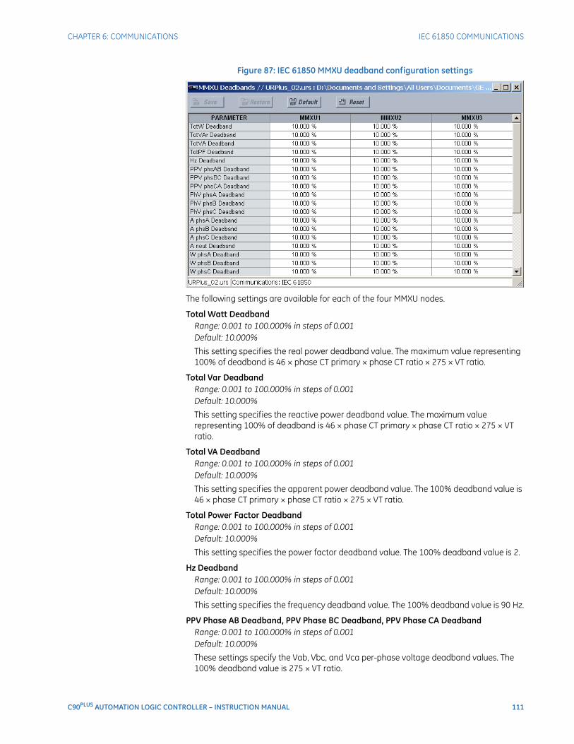
CHAPTER 6: COMMUNICATIONS IEC 61850 COMMUNICATIONS
C90PLUS AUTOMATION LOGIC CONTROLLER – INSTRUCTION MANUAL 111
Figure 87: IEC 61850 MMXU deadband configuration settings
The following settings are available for each of the four MMXU nodes.
Total Watt DeadbandRange: 0.001 to 100.000% in steps of 0.001Default: 10.000%
This setting specifies the real power deadband value. The maximum value representing 100% of deadband is 46 × phase CT primary × phase CT ratio × 275 × VT ratio.
Total Var DeadbandRange: 0.001 to 100.000% in steps of 0.001Default: 10.000%
This setting specifies the reactive power deadband value. The maximum value representing 100% of deadband is 46 × phase CT primary × phase CT ratio × 275 × VT ratio.
Total VA DeadbandRange: 0.001 to 100.000% in steps of 0.001Default: 10.000%
This setting specifies the apparent power deadband value. The 100% deadband value is 46 × phase CT primary × phase CT ratio × 275 × VT ratio.
Total Power Factor DeadbandRange: 0.001 to 100.000% in steps of 0.001Default: 10.000%
This setting specifies the power factor deadband value. The 100% deadband value is 2.
Hz DeadbandRange: 0.001 to 100.000% in steps of 0.001Default: 10.000%
This setting specifies the frequency deadband value. The 100% deadband value is 90 Hz.
PPV Phase AB Deadband, PPV Phase BC Deadband, PPV Phase CA DeadbandRange: 0.001 to 100.000% in steps of 0.001Default: 10.000%
These settings specify the Vab, Vbc, and Vca per-phase voltage deadband values. The 100% deadband value is 275 × VT ratio.
112 C90PLUS AUTOMATION LOGIC CONTROLLER – INSTRUCTION MANUAL
IEC 61850 COMMUNICATIONS CHAPTER 6: COMMUNICATIONS
PhV Phase A Deadband, PhV Phase B Deadband, PhV Phase C DeadbandRange: 0.001 to 100.000% in steps of 0.001Default: 10.000%
These settings specify the Va, Vb, and Vc phase voltage deadband values. The 100% deadband value is 275 × VT ratio.
Current Phase A Deadband, Current Phase B Deadband, Current Phase C DeadbandRange: 0.001 to 100.000% in steps of 0.001Default: 10.000%
These settings specify the Ia, Ib, and Ic phase current deadband values. The 100% deadband value is 46 × phase CT primary × phase CT ratio.
Current Neutral DeadbandRange: 0.001 to 100.00% in steps of 0.001Default: 10.000%
This setting specifies the neutral current deadband value. The 100% deadband value is 46 × ground CT primary.
Watt Phase A Deadband, Watt Phase B Deadband, Watt Phase C DeadbandRange: 0.001 to 100.000% in steps of 0.001Default: 10.000%
These settings specify the real per-phase power deadband values. The maximum value representing 100% of deadband is 46 × phase CT primary × phase CT ratio × 275 × VT ratio.
Var Phase A Deadband, Var Phase B Deadband, Var Phase C DeadbandRange: 0.001 to 100.000% in steps of 0.001Default: 10.000%
These settings specify the reactive per-phase power deadband values. The maximum value representing 100% of deadband is 46 × phase CT primary × phase CT ratio × 275 × VT ratio.
VA Phase A Deadband, VA Phase B Deadband, VA Phase C DeadbandRange: 0.001 to 100.000% in steps of 0.001Default: 10.000%
These settings specify the apparent per-phase power deadband values. The maximum value representing 100% of deadband is 46 × phase CT primary × phase CT ratio × 275 × VT ratio.
Power Factor Phase A Deadband, Power Factor Phase B Deadband, Power Factor Phase C Deadband
Range: 0.001 to 100.000% in steps of 0.001Default: 10.000%
These settings specify the per-phase power factor deadband values. The maximum value representing 100% of deadband is 2.
GGIO1 status configurationThe GGIO1 logical node provides access to as many 128 digital status points and associated timestamps and quality flags. It is intended that clients use GGIO1 in order to access digital status values from the C90Plus. Configuration settings are provided to allow the selection of the number of digital status indications available in GGIO1 (8 to 128) and to select logic operands to drive the status of the GGIO1 status indications. Clients can utilize the IEC 61850 buffered and unbuffered reporting features available from GGIO1 to build sequence of events (SOE) logs and HMI display screens. Buffered reporting should
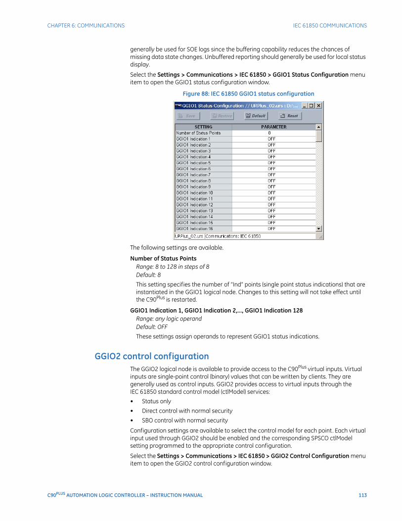
CHAPTER 6: COMMUNICATIONS IEC 61850 COMMUNICATIONS
C90PLUS AUTOMATION LOGIC CONTROLLER – INSTRUCTION MANUAL 113
generally be used for SOE logs since the buffering capability reduces the chances of missing data state changes. Unbuffered reporting should generally be used for local status display.
Select the Settings > Communications > IEC 61850 > GGIO1 Status Configuration menu item to open the GGIO1 status configuration window.
Figure 88: IEC 61850 GGIO1 status configuration
The following settings are available.
Number of Status PointsRange: 8 to 128 in steps of 8Default: 8
This setting specifies the number of “Ind” points (single point status indications) that are instantiated in the GGIO1 logical node. Changes to this setting will not take effect until the C90Plus is restarted.
GGIO1 Indication 1, GGIO1 Indication 2,..., GGIO1 Indication 128Range: any logic operandDefault: OFF
These settings assign operands to represent GGIO1 status indications.
GGIO2 control configurationThe GGIO2 logical node is available to provide access to the C90Plus virtual inputs. Virtual inputs are single-point control (binary) values that can be written by clients. They are generally used as control inputs. GGIO2 provides access to virtual inputs through the IEC 61850 standard control model (ctlModel) services:
• Status only
• Direct control with normal security
• SBO control with normal security
Configuration settings are available to select the control model for each point. Each virtual input used through GGIO2 should be enabled and the corresponding SPSCO ctlModel setting programmed to the appropriate control configuration.
Select the Settings > Communications > IEC 61850 > GGIO2 Control Configuration menu item to open the GGIO2 control configuration window.
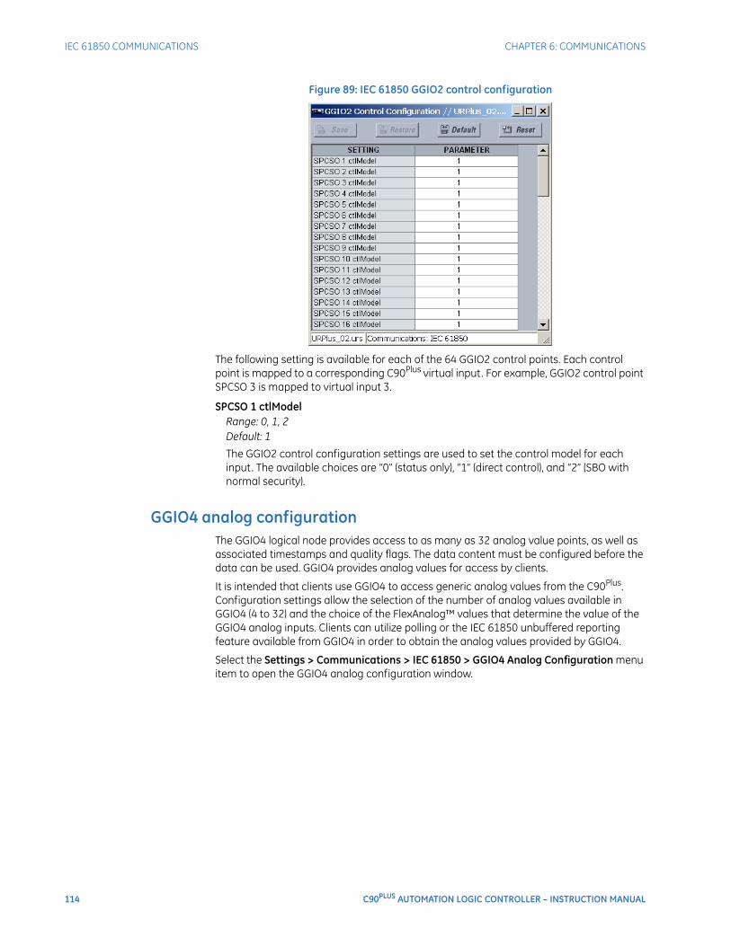
114 C90PLUS AUTOMATION LOGIC CONTROLLER – INSTRUCTION MANUAL
IEC 61850 COMMUNICATIONS CHAPTER 6: COMMUNICATIONS
Figure 89: IEC 61850 GGIO2 control configuration
The following setting is available for each of the 64 GGIO2 control points. Each control point is mapped to a corresponding C90Plus virtual input. For example, GGIO2 control point SPCSO 3 is mapped to virtual input 3.
SPCSO 1 ctlModelRange: 0, 1, 2Default: 1
The GGIO2 control configuration settings are used to set the control model for each input. The available choices are “0” (status only), “1” (direct control), and “2” (SBO with normal security).
GGIO4 analog configurationThe GGIO4 logical node provides access to as many as 32 analog value points, as well as associated timestamps and quality flags. The data content must be configured before the data can be used. GGIO4 provides analog values for access by clients.
It is intended that clients use GGIO4 to access generic analog values from the C90Plus. Configuration settings allow the selection of the number of analog values available in GGIO4 (4 to 32) and the choice of the FlexAnalog™ values that determine the value of the GGIO4 analog inputs. Clients can utilize polling or the IEC 61850 unbuffered reporting feature available from GGIO4 in order to obtain the analog values provided by GGIO4.
Select the Settings > Communications > IEC 61850 > GGIO4 Analog Configuration menu item to open the GGIO4 analog configuration window.
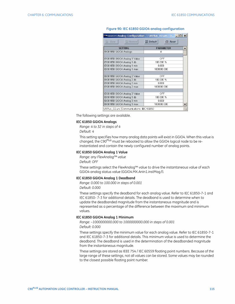
CHAPTER 6: COMMUNICATIONS IEC 61850 COMMUNICATIONS
C90PLUS AUTOMATION LOGIC CONTROLLER – INSTRUCTION MANUAL 115
Figure 90: IEC 61850 GGIO4 analog configuration
The following settings are available.
IEC 61850 GGIO4 AnalogsRange: 4 to 32 in steps of 4Default: 4
This setting specifies how many analog data points will exist in GGIO4. When this value is changed, the C90Plus must be rebooted to allow the GGIO4 logical node to be re-instantiated and contain the newly configured number of analog points.
IEC 61850 GGIO4 Analog 1 ValueRange: any FlexAnalog™ valueDefault: OFF
These settings select the FlexAnalog™ value to drive the instantaneous value of each GGIO4 analog status value (GGIO4.MX.AnIn1.instMag.f).
IEC 61850 GGIO4 Analog 1 DeadbandRange: 0.000 to 100.000 in steps of 0.001Default: 0.000
These settings specify the deadband for each analog value. Refer to IEC 61850-7-1 and IEC 61850- 7-3 for additional details. The deadband is used to determine when to update the deadbanded magnitude from the instantaneous magnitude and is represented as a percentage of the difference between the maximum and minimum values.
IEC 61850 GGIO4 Analog 1 MinimumRange: –1000000000.000 to 1000000000.000 in steps of 0.001Default: 0.000
These settings specify the minimum value for each analog value. Refer to IEC 61850-7-1 and IEC 61850-7-3 for additional details. This minimum value is used to determine the deadband. The deadband is used in the determination of the deadbanded magnitude from the instantaneous magnitude.
These settings are stored as IEEE 754 / IEC 60559 floating point numbers. Because of the large range of these settings, not all values can be stored. Some values may be rounded to the closest possible floating point number.
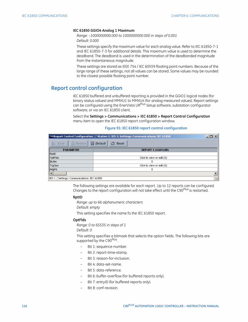
116 C90PLUS AUTOMATION LOGIC CONTROLLER – INSTRUCTION MANUAL
IEC 61850 COMMUNICATIONS CHAPTER 6: COMMUNICATIONS
IEC 61850 GGIO4 Analog 1 MaximumRange: –1000000000.000 to 1000000000.000 in steps of 0.001Default: 0.000
These settings specify the maximum value for each analog value. Refer to IEC 61850-7-1 and IEC 61850-7-3 for additional details. This maximum value is used to determine the deadband. The deadband is used in the determination of the deadbanded magnitude from the instantaneous magnitude.
These settings are stored as IEEE 754 / IEC 60559 floating point numbers. Because of the large range of these settings, not all values can be stored. Some values may be rounded to the closest possible floating point number.
Report control configurationIEC 61850 buffered and unbuffered reporting is provided in the GGIO1 logical nodes (for binary status values) and MMXU1 to MMXU4 (for analog measured values). Report settings can be configured using the EnerVista URPlus Setup software, substation configurator software, or via an IEC 61850 client.
Select the Settings > Communications > IEC 61850 > Report Control Configuration menu item to open the IEC 61850 report configuration window.
Figure 91: IEC 61850 report control configuration
The following settings are available for each report. Up to 12 reports can be configured. Changes to the report configuration will not take effect until the C90Plus is restarted.
RptIDRange: up to 66 alphanumeric charactersDefault: empty
This setting specifies the name fo the IEC 61850 report.
OptFldsRange: 0 to 65535 in steps of 1Default: 0
This setting specifies a bitmask that selects the option fields. The following bits are supported by the C90Plus.
– Bit 1: sequence-number.
– Bit 2: report-time-stamp.
– Bit 3: reason-for-inclusion.
– Bit 4: data-set-name.
– Bit 5: data-reference.
– Bit 6: buffer-overflow (for buffered reports only).
– Bit 7: entryID (for buffered reports only).
– Bit 8: conf-revision.
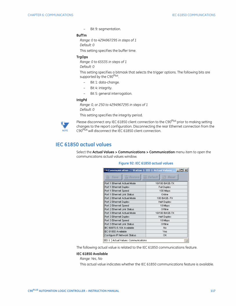
CHAPTER 6: COMMUNICATIONS IEC 61850 COMMUNICATIONS
C90PLUS AUTOMATION LOGIC CONTROLLER – INSTRUCTION MANUAL 117
– Bit 9: segmentation.
BufTmRange: 0 to 4294967295 in steps of 1Default: 0
This setting specifies the buffer time.
TrgOpsRange: 0 to 65535 in steps of 1Default: 0
This setting specifies a bitmask that selects the trigger options. The following bits are supported by the C90Plus.
– Bit 1: data-change.
– Bit 4: integrity.
– Bit 5: general interrogation.
IntgPdRange: 0, or 250 to 4294967295 in steps of 1Default: 0
This setting specifies the integrity period.
NOTE
NOTE: Please disconnect any IEC 61850 client connection to the C90Plus prior to making setting changes to the report configuration. Disconnecting the rear Ethernet connection from the C90Plus will disconnect the IEC 61850 client connection.
IEC 61850 actual valuesSelect the Actual Values > Communications > Communication menu item to open the communications actual values window.
Figure 92: IEC 61850 actual values
The following actual value is related to the IEC 61850 communications feature.
IEC 61850 AvailableRange: Yes, No
This actual value indicates whether the IEC 61850 communications feature is available.
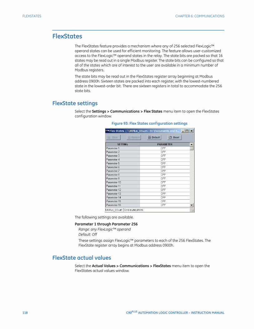
118 C90PLUS AUTOMATION LOGIC CONTROLLER – INSTRUCTION MANUAL
FLEXSTATES CHAPTER 6: COMMUNICATIONS
FlexStatesThe FlexStates feature provides a mechanism where any of 256 selected FlexLogic™ operand states can be used for efficient monitoring. The feature allows user-customized access to the FlexLogic™ operand states in the relay. The state bits are packed so that 16 states may be read out in a single Modbus register. The state bits can be configured so that all of the states which are of interest to the user are available in a minimum number of Modbus registers.
The state bits may be read out in the FlexStates register array beginning at Modbus address 0900h. Sixteen states are packed into each register, with the lowest-numbered state in the lowest-order bit. There are sixteen registers in total to accommodate the 256 state bits.
FlexState settingsSelect the Settings > Communications > Flex States menu item to open the FlexStates configuration window.
Figure 93: Flex States configuration settings
The following settings are available.
Parameter 1 through Parameter 256Range: any FlexLogic™ operandDefault: Off
These settings assign FlexLogic™ parameters to each of the 256 FlexStates. The FlexState register array begins at Modbus address 0900h.
FlexState actual valuesSelect the Actual Values > Communications > FlexStates menu item to open the FlexStates actual values window.
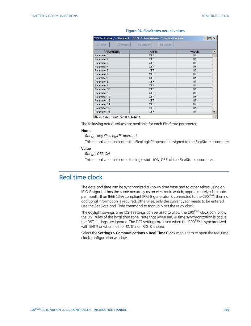
CHAPTER 6: COMMUNICATIONS REAL TIME CLOCK
C90PLUS AUTOMATION LOGIC CONTROLLER – INSTRUCTION MANUAL 119
Figure 94: FlexStates actual values
The following actual values are available for each FlexState parameter.
NameRange: any FlexLogic™ operand
This actual value indicates the FlexLogic™ operand assigned to the FlexState parameter
ValueRange: OFF, ON
This actual value indicates the logic state (ON, OFF) of the FlexState parameter.
Real time clockThe date and time can be synchronized a known time base and to other relays using an IRIG-B signal. It has the same accuracy as an electronic watch, approximately ±1 minute per month. If an IEEE 1344 compliant IRIG-B generator is connected to the C90Plus, then no additional information is required. Otherwise, only the current year needs to be entered. Use the Set Date and Time command to manually set the relay clock.
The daylight savings time (DST) settings can be used to allow the C90Plus clock can follow the DST rules of the local time zone. Note that when IRIG-B time synchronization is active, the DST settings are ignored. The DST settings are used when the C90Plus is synchronized with SNTP, or when neither SNTP nor IRIG-B is used.
Select the Settings > Communications > Real Time Clock menu item to open the real time clock configuration window.
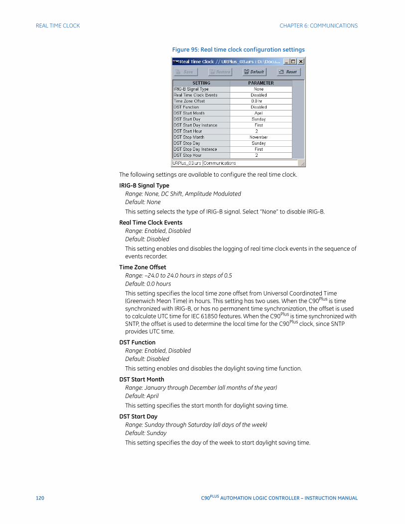
120 C90PLUS AUTOMATION LOGIC CONTROLLER – INSTRUCTION MANUAL
REAL TIME CLOCK CHAPTER 6: COMMUNICATIONS
Figure 95: Real time clock configuration settings
The following settings are available to configure the real time clock.
IRIG-B Signal TypeRange: None, DC Shift, Amplitude ModulatedDefault: None
This setting selects the type of IRIG-B signal. Select “None” to disable IRIG-B.
Real Time Clock EventsRange: Enabled, DisabledDefault: Disabled
This setting enables and disables the logging of real time clock events in the sequence of events recorder.
Time Zone OffsetRange: –24.0 to 24.0 hours in steps of 0.5Default: 0.0 hours
This setting specifies the local time zone offset from Universal Coordinated Time (Greenwich Mean Time) in hours. This setting has two uses. When the C90Plus is time synchronized with IRIG-B, or has no permanent time synchronization, the offset is used to calculate UTC time for IEC 61850 features. When the C90Plus is time synchronized with SNTP, the offset is used to determine the local time for the C90Plus clock, since SNTP provides UTC time.
DST FunctionRange: Enabled, DisabledDefault: Disabled
This setting enables and disables the daylight saving time function.
DST Start MonthRange: January through December (all months of the year)Default: April
This setting specifies the start month for daylight saving time.
DST Start DayRange: Sunday through Saturday (all days of the week)Default: Sunday
This setting specifies the day of the week to start daylight saving time.
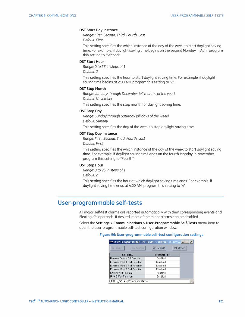
CHAPTER 6: COMMUNICATIONS USER-PROGRAMMABLE SELF-TESTS
C90PLUS AUTOMATION LOGIC CONTROLLER – INSTRUCTION MANUAL 121
DST Start Day InstanceRange: First, Second, Third, Fourth, LastDefault: First
This setting specifies the which instance of the day of the week to start daylight saving time. For example, if daylight saving time begins on the second Monday in April, program this setting to “Second”.
DST Start HourRange: 0 to 23 in steps of 1Default: 2
This setting specifies the hour to start daylight saving time. For example, if daylight saving time begins at 2:00 AM, program this setting to “2”.
DST Stop MonthRange: January through December (all months of the year)Default: November
This setting specifies the stop month for daylight saving time.
DST Stop DayRange: Sunday through Saturday (all days of the week)Default: Sunday
This setting specifies the day of the week to stop daylight saving time.
DST Stop Day InstanceRange: First, Second, Third, Fourth, LastDefault: First
This setting specifies the which instance of the day of the week to start daylight saving time. For example, if daylight saving time ends on the fourth Monday in November, program this setting to “Fourth”.
DST Stop HourRange: 0 to 23 in steps of 1Default: 2
This setting specifies the hour at which daylight saving time ends. For example, if daylight saving time ends at 4:00 AM, program this setting to “4”.
User-programmable self-testsAll major self-test alarms are reported automatically with their corresponding events and FlexLogic™ operands. If desired, most of the minor alarms can be disabled.
Select the Settings > Communications > User-Programmable Self-Tests menu item to open the user-programmable self-test configuration window.
Figure 96: User-programmable self-test configuration settings

122 C90PLUS AUTOMATION LOGIC CONTROLLER – INSTRUCTION MANUAL
SERIAL PORT CHAPTER 6: COMMUNICATIONS
The following settings are available to configure the user-programmable self-tests.
Ethernet Port 1 Fail FunctionRange: Enabled, DisabledDefault: Enabled
When this setting is “Disabled”, the ETHERNET PORT 1 FAILURE alarm will not assert a FlexLogic™ operand or write to the event recorder. Moreover, it will not trigger the ANY MINOR ALARM or ANY SELF-TEST messages. When this setting is “Enabled”, the ETHERNET PORT 1 FAILURE alarm continues to function along with other major and minor alarms. Refer to the Relay self-tests section in for additional information on major and minor self-test alarms.
Ethernet Port 2 Fail FunctionRange: Enabled, DisabledDefault: Disabled
When this setting is “Disabled”, the ETHERNET PORT 2 FAILURE alarm will not assert a FlexLogic™ operand or write to the event recorder. Moreover, it will not trigger the ANY MINOR ALARM or ANY SELF-TEST messages. When this setting is “Enabled”, the ETHERNET PORT 2 FAILURE alarm continues to function along with other major and minor alarms. Refer to the Relay self-tests section in for additional information on major and minor self-test alarms.
Ethernet Port 3 Fail FunctionRange: Enabled, DisabledDefault: Disabled
When this setting is “Disabled”, the ETHERNET PORT 3 FAILURE alarm will not assert a FlexLogic™ operand or write to the event recorder. Moreover, it will not trigger the ANY MINOR ALARM or ANY SELF-TEST messages. When this setting is “Enabled”, the ETHERNET PORT 3 FAILURE alarm continues to function along with other major and minor alarms. Refer to the Relay self-tests section in for additional information on major and minor self-test alarms.
SNTP Fail FunctionRange: Enabled, DisabledDefault: Enabled
When this setting is “Disabled”, the SNTP FAILURE alarm will not assert a FlexLogic™ operand or write to the event recorder. Moreover, it will not trigger the ANY MINOR ALARM or ANY SELF-TEST messages. When this setting is “Enabled”, the SNTP FAILURE alarm continues to function along with other major and minor alarms. Refer to the Relay self-tests section in for additional information on major and minor self-test alarms.
IRIG-B Fail FunctionRange: Enabled, DisabledDefault: Enabled
When this setting is “Disabled”, the IRIG-B FAILURE alarm will not assert a FlexLogic™ operand or write to the event recorder. Moreover, it will not trigger the ANY MINOR ALARM or ANY SELF-TEST messages. When this setting is “Enabled”, the IRIG-B FAILURE alarm continues to function along with other major and minor alarms. Refer to the Relay self-tests section in for additional information on major and minor self-test alarms.
Serial portThe C90Plus is equipped with one serial RS485 communication port. The RS485 port has settings for baud rate and parity. It is important that these parameters agree with the settings used on the computer or other equipment that is connected to these ports. This
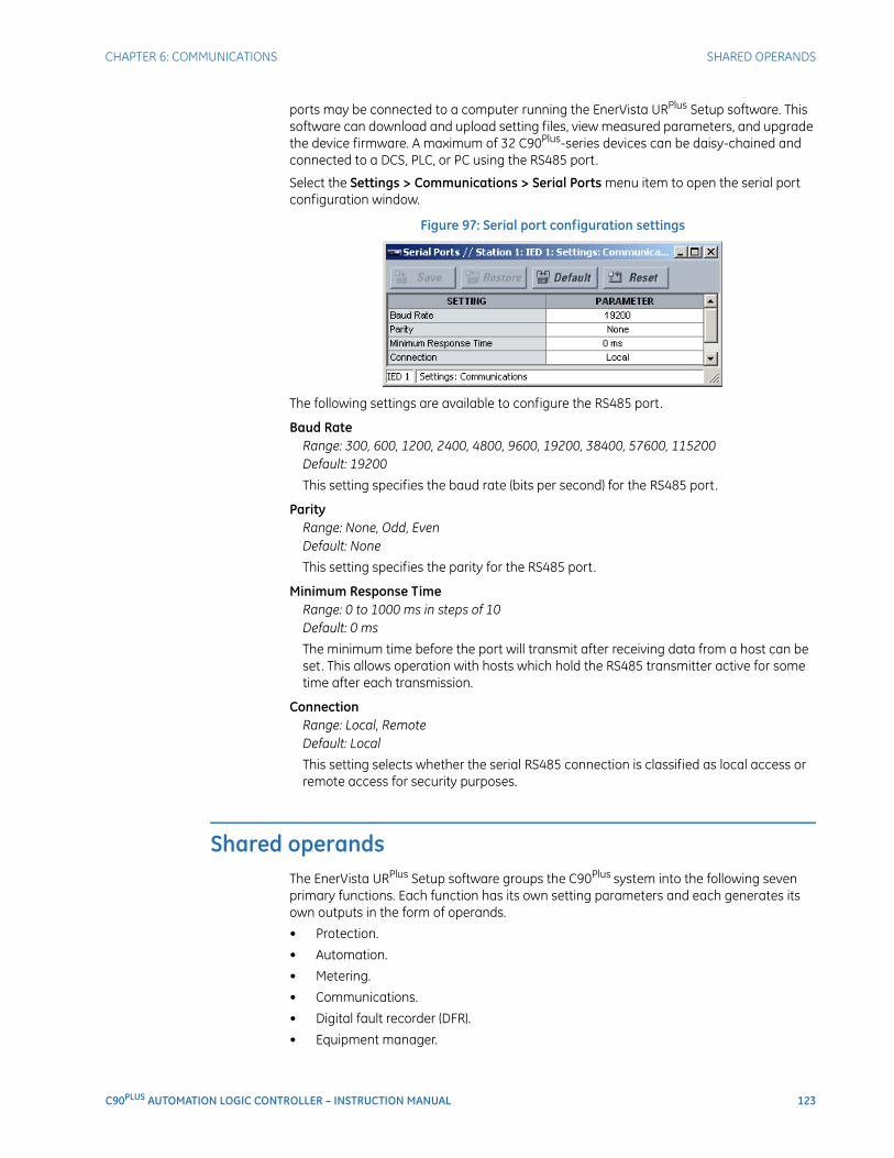
CHAPTER 6: COMMUNICATIONS SHARED OPERANDS
C90PLUS AUTOMATION LOGIC CONTROLLER – INSTRUCTION MANUAL 123
ports may be connected to a computer running the EnerVista URPlus Setup software. This software can download and upload setting files, view measured parameters, and upgrade the device firmware. A maximum of 32 C90Plus-series devices can be daisy-chained and connected to a DCS, PLC, or PC using the RS485 port.
Select the Settings > Communications > Serial Ports menu item to open the serial port configuration window.
Figure 97: Serial port configuration settings
The following settings are available to configure the RS485 port.
Baud RateRange: 300, 600, 1200, 2400, 4800, 9600, 19200, 38400, 57600, 115200Default: 19200
This setting specifies the baud rate (bits per second) for the RS485 port.
ParityRange: None, Odd, EvenDefault: None
This setting specifies the parity for the RS485 port.
Minimum Response TimeRange: 0 to 1000 ms in steps of 10Default: 0 ms
The minimum time before the port will transmit after receiving data from a host can be set. This allows operation with hosts which hold the RS485 transmitter active for some time after each transmission.
ConnectionRange: Local, RemoteDefault: Local
This setting selects whether the serial RS485 connection is classified as local access or remote access for security purposes.
Shared operandsThe EnerVista URPlus Setup software groups the C90Plus system into the following seven primary functions. Each function has its own setting parameters and each generates its own outputs in the form of operands.
• Protection.
• Automation.
• Metering.
• Communications.
• Digital fault recorder (DFR).
• Equipment manager.
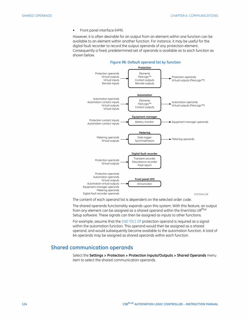
124 C90PLUS AUTOMATION LOGIC CONTROLLER – INSTRUCTION MANUAL
SHARED OPERANDS CHAPTER 6: COMMUNICATIONS
• Front panel interface (HMI).
However, it is often desirable for an output from an element within one function can be available to an element within another function. For instance, it may be useful for the digital fault recorder to record the output operands of any protection element. Consequently a fixed, predetermined set of operands is available as to each function as shown below.
Figure 98: Default operand list by function
The content of each operand list is dependent on the selected order code.
The shared operands functionality expands upon this system. With this feature, an output from any element can be assigned as a shared operand within the EnerVista URPlus Setup software. These signals can then be assigned as inputs to other functions.
For example, assume that the GND TOC1 OP protection operand is required as a signal within the automation function. This operand would then be assigned as a shared operand, and would subsequently become available to the automation function. A total of 64 operands may be assigned as shared operands within each function.
Shared communication operandsSelect the Settings > Protection > Protection Inputs/Outputs > Shared Operands menu item to select the shared communication operands.
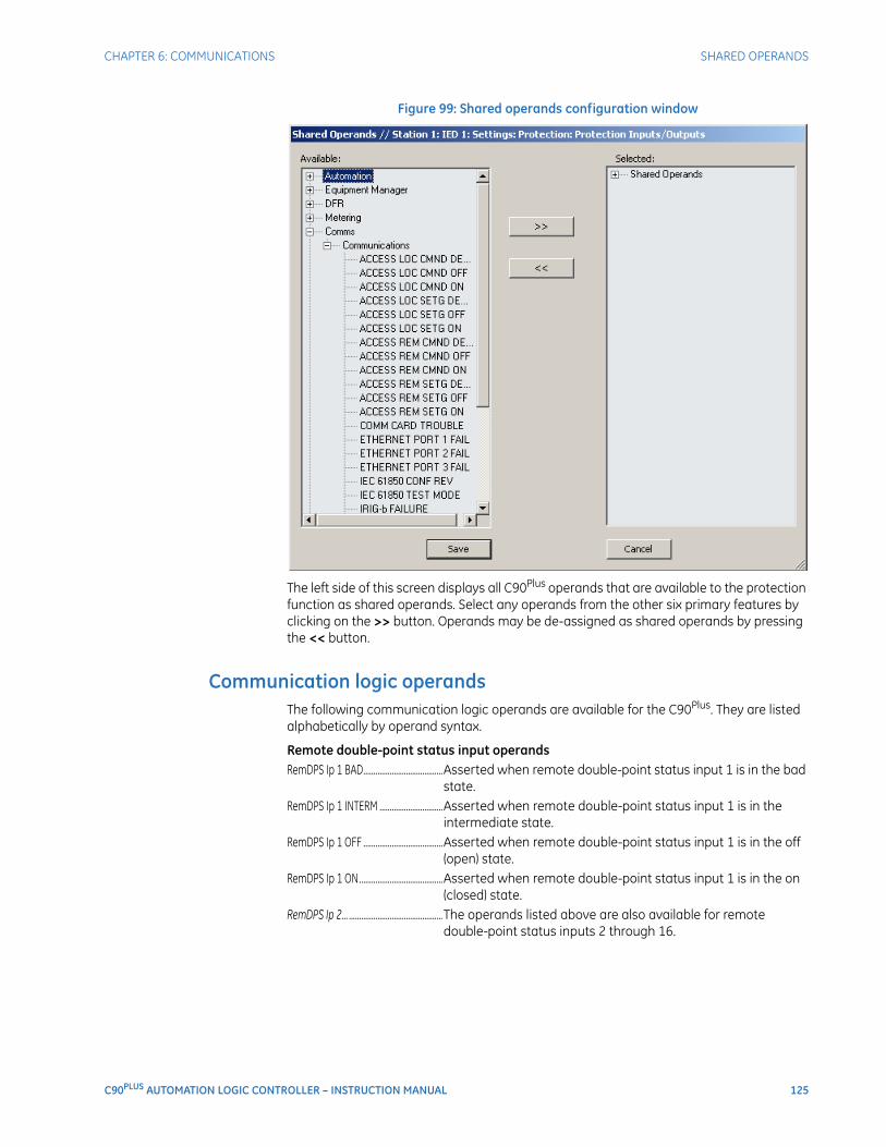
CHAPTER 6: COMMUNICATIONS SHARED OPERANDS
C90PLUS AUTOMATION LOGIC CONTROLLER – INSTRUCTION MANUAL 125
Figure 99: Shared operands configuration window
The left side of this screen displays all C90Plus operands that are available to the protection function as shared operands. Select any operands from the other six primary features by clicking on the >> button. Operands may be de-assigned as shared operands by pressing the << button.
Communication logic operandsThe following communication logic operands are available for the C90Plus. They are listed alphabetically by operand syntax.
Remote double-point status input operandsRemDPS Ip 1 BAD.......................................Asserted when remote double-point status input 1 is in the bad
state.RemDPS Ip 1 INTERM ...............................Asserted when remote double-point status input 1 is in the
intermediate state.RemDPS Ip 1 OFF .......................................Asserted when remote double-point status input 1 is in the off
(open) state.RemDPS Ip 1 ON.........................................Asserted when remote double-point status input 1 is in the on
(closed) state.RemDPS Ip 2... ..............................................The operands listed above are also available for remote
double-point status inputs 2 through 16.

126 C90PLUS AUTOMATION LOGIC CONTROLLER – INSTRUCTION MANUAL
SHARED OPERANDS CHAPTER 6: COMMUNICATIONS
C90PLUS AUTOMATION LOGIC CONTROLLER – INSTRUCTION MANUAL 127
C90Plus Automation Logic Controller
Chapter 7: Protection
Protection
This section describes how to program the C90Plus protection features.
Protection overviewThe C90Plus is an advanced logic controller specifically designed for use in substation environments and for the unique automation requirements of industrial and utility power systems. The C90Plus provides powerful logic processing with deterministic execution of logic equations regardless of the amount of configured logic.
The C90Plus provides the tools and functionality necessary for creating customized automation and control schemes that include complete bay control, breaker monitoring and control, auto-restoration schemes, automatic bus transfer schemes, and load shedding schemes.
In addition, overcurrent and undervoltage protection, fault diagnostics, power metering, and RTU functions are provided. The C90Plus provides phase, neutral, and ground time overcurrent protection. The time overcurrent functions can be programmed with multiple curve shapes or FlexCurves™ for optimum coordination.
Introduction to protection elementsIn the design of the URPlus-series protection system, the term element is used to describe a feature based around a comparator. The comparator is provided with an input (or set of inputs) that is tested against a programmed setting (or group of settings) to determine if the input is within the defined range that will set the output to logic 1, also referred to as setting the flag. A single comparator may make multiple tests and provide multiple outputs. For example, the time overcurrent comparator sets a pickup flag when the current input is above the setting and sets an operate flag when the input current has been at a level above the pickup setting for the time specified by the time-current curve settings. All comparators use analog parameter actual values as the input.
Protection elements are arranged into two classes, grouped and control. Each element classed as a grouped element is provided with six alternate sets of settings, in setting groups numbered 1 through 6. The performance of a grouped element is defined by the setting group that is active at a given time. The performance of a control element is independent of the selected active setting group.
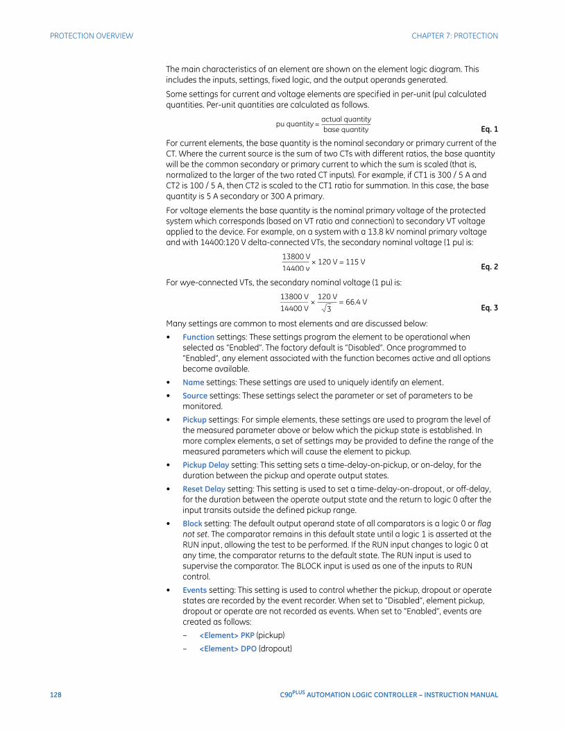
128 C90PLUS AUTOMATION LOGIC CONTROLLER – INSTRUCTION MANUAL
PROTECTION OVERVIEW CHAPTER 7: PROTECTION
The main characteristics of an element are shown on the element logic diagram. This includes the inputs, settings, fixed logic, and the output operands generated.
Some settings for current and voltage elements are specified in per-unit (pu) calculated quantities. Per-unit quantities are calculated as follows.
Eq. 1
For current elements, the base quantity is the nominal secondary or primary current of the CT. Where the current source is the sum of two CTs with different ratios, the base quantity will be the common secondary or primary current to which the sum is scaled (that is, normalized to the larger of the two rated CT inputs). For example, if CT1 is 300 / 5 A and CT2 is 100 / 5 A, then CT2 is scaled to the CT1 ratio for summation. In this case, the base quantity is 5 A secondary or 300 A primary.
For voltage elements the base quantity is the nominal primary voltage of the protected system which corresponds (based on VT ratio and connection) to secondary VT voltage applied to the device. For example, on a system with a 13.8 kV nominal primary voltage and with 14400:120 V delta-connected VTs, the secondary nominal voltage (1 pu) is:
Eq. 2
For wye-connected VTs, the secondary nominal voltage (1 pu) is:
Eq. 3
Many settings are common to most elements and are discussed below:
• Function settings: These settings program the element to be operational when selected as “Enabled”. The factory default is “Disabled”. Once programmed to “Enabled”, any element associated with the function becomes active and all options become available.
• Name settings: These settings are used to uniquely identify an element.
• Source settings: These settings select the parameter or set of parameters to be monitored.
• Pickup settings: For simple elements, these settings are used to program the level of the measured parameter above or below which the pickup state is established. In more complex elements, a set of settings may be provided to define the range of the measured parameters which will cause the element to pickup.
• Pickup Delay setting: This setting sets a time-delay-on-pickup, or on-delay, for the duration between the pickup and operate output states.
• Reset Delay setting: This setting is used to set a time-delay-on-dropout, or off-delay, for the duration between the operate output state and the return to logic 0 after the input transits outside the defined pickup range.
• Block setting: The default output operand state of all comparators is a logic 0 or flag not set. The comparator remains in this default state until a logic 1 is asserted at the RUN input, allowing the test to be performed. If the RUN input changes to logic 0 at any time, the comparator returns to the default state. The RUN input is used to supervise the comparator. The BLOCK input is used as one of the inputs to RUN control.
• Events setting: This setting is used to control whether the pickup, dropout or operate states are recorded by the event recorder. When set to “Disabled”, element pickup, dropout or operate are not recorded as events. When set to “Enabled”, events are created as follows:
– <Element> PKP (pickup)
– <Element> DPO (dropout)

CHAPTER 7: PROTECTION POWER SYSTEM
C90PLUS AUTOMATION LOGIC CONTROLLER – INSTRUCTION MANUAL 129
– <Element> OP (operate)
The dropout event is created when the measure and decide comparator output transits from the pickup state (logic 1) to the dropout state (logic 0). This could happen when the element is in the operate state if the reset delay time is not zero.
Power systemThe following section describes settings relevant to the C90Plus power system.
Installation settingsSelect the Settings > Protection > Power System > Installation menu item to open the installation settings window.
Figure 100: Installation settings
The following settings are available.
Relay SettingsRange: Programmed, Not ProgrammedDefault: Not Programmed
To safeguard against the installation of a device without any entered settings, the C90Plus will not allow signaling of any output relay until this setting value is “Programmed”. This setting is defaulted to “Not Programmed” when at the factory. The UNIT NOT PROGRAMMED self-test error message is displayed until the relay is put into the programmed state.
Relay NameRange: up to 20 alphanumeric charactersDefault: -----
This setting allows the user to uniquely identify a relay. This name will appear on all generated reports.
User Configuration NameRange: up to 20 alphanumeric charactersDefault: Initial
This setting allows the user to provide a description for the settings that are loaded at a particular time (for example, “Spring-summer settings”). This description is displayed on the Product Information page of the front panel annunciator under the Configuration field.
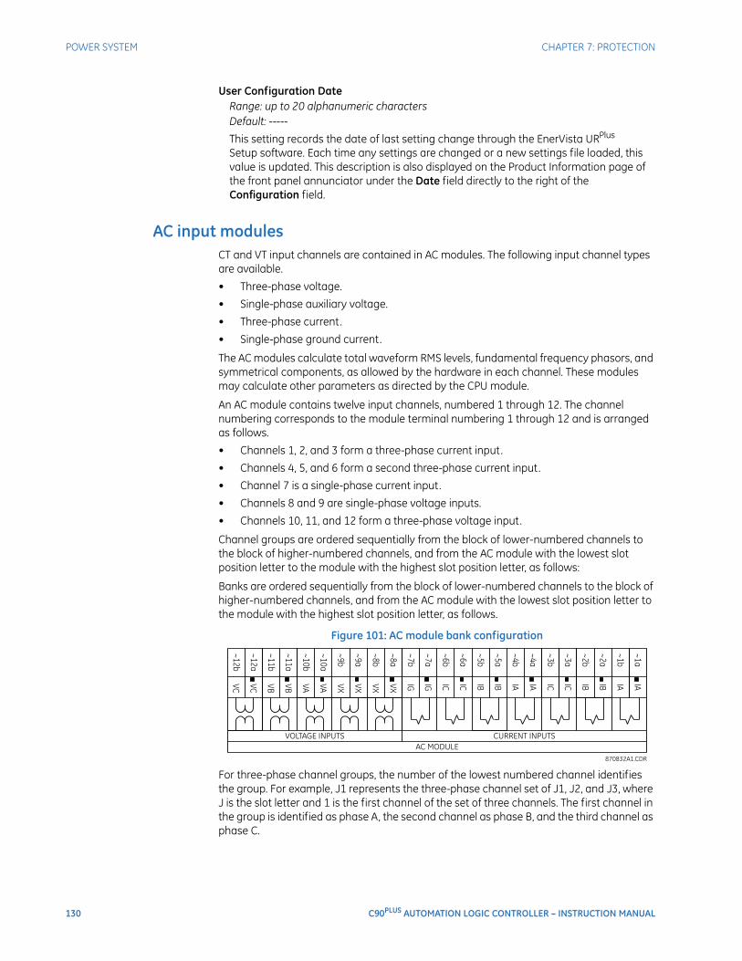
130 C90PLUS AUTOMATION LOGIC CONTROLLER – INSTRUCTION MANUAL
POWER SYSTEM CHAPTER 7: PROTECTION
User Configuration DateRange: up to 20 alphanumeric charactersDefault: -----
This setting records the date of last setting change through the EnerVista URPlus Setup software. Each time any settings are changed or a new settings file loaded, this value is updated. This description is also displayed on the Product Information page of the front panel annunciator under the Date field directly to the right of the Configuration field.
AC input modulesCT and VT input channels are contained in AC modules. The following input channel types are available.
• Three-phase voltage.
• Single-phase auxiliary voltage.
• Three-phase current.
• Single-phase ground current.
The AC modules calculate total waveform RMS levels, fundamental frequency phasors, and symmetrical components, as allowed by the hardware in each channel. These modules may calculate other parameters as directed by the CPU module.
An AC module contains twelve input channels, numbered 1 through 12. The channel numbering corresponds to the module terminal numbering 1 through 12 and is arranged as follows.
• Channels 1, 2, and 3 form a three-phase current input.
• Channels 4, 5, and 6 form a second three-phase current input.
• Channel 7 is a single-phase current input.
• Channels 8 and 9 are single-phase voltage inputs.
• Channels 10, 11, and 12 form a three-phase voltage input.
Channel groups are ordered sequentially from the block of lower-numbered channels to the block of higher-numbered channels, and from the AC module with the lowest slot position letter to the module with the highest slot position letter, as follows:
Banks are ordered sequentially from the block of lower-numbered channels to the block of higher-numbered channels, and from the AC module with the lowest slot position letter to the module with the highest slot position letter, as follows.
Figure 101: AC module bank configuration
For three-phase channel groups, the number of the lowest numbered channel identifies the group. For example, J1 represents the three-phase channel set of J1, J2, and J3, where J is the slot letter and 1 is the first channel of the set of three channels. The first channel in the group is identified as phase A, the second channel as phase B, and the third channel as phase C.
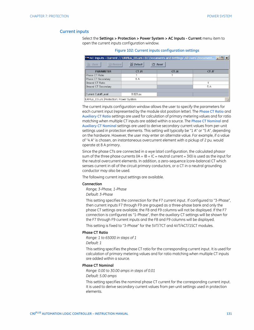
CHAPTER 7: PROTECTION POWER SYSTEM
C90PLUS AUTOMATION LOGIC CONTROLLER – INSTRUCTION MANUAL 131
Current inputsSelect the Settings > Protection > Power System > AC Inputs - Current menu item to open the current inputs configuration window.
Figure 102: Current inputs configuration settings
The current inputs configuration window allows the user to specify the parameters for each current input (represented by the module slot position letter). The Phase CT Ratio and Auxiliary CT Ratio settings are used for calculation of primary metering values and for ratio matching when multiple CT inputs are added within a source. The Phase CT Nominal and Auxiliary CT Nominal settings are used to derive secondary current values from per-unit settings used in protection elements. This setting will typically be “1 A” or “5 A”, depending on the hardware. However, the user may enter an alternate value. For example, if a value of “4 A” is chosen, an instantaneous overcurrent element with a pickup of 2 pu. would operate at 8 A primary.
Since the phase CTs are connected in a wye (star) configuration, the calculated phasor sum of the three phase currents (IA + IB + IC = neutral current = 3I0) is used as the input for the neutral overcurrent elements. In addition, a zero-sequence (core-balance) CT which senses current in all of the circuit primary conductors, or a CT in a neutral grounding conductor may also be used.
The following current input settings are available.
ConnectionRange; 3-Phase, 1-PhaseDefault: 3-Phase
This setting specifies the connection for the F7 current input. If configured to “3-Phase”, then current inputs F7 through F9 are grouped as a three-phase bank and only the phase CT settings are available; the F8 and F9 columns will not be displayed. If the F7 connection is configured as “1-Phase”, then the auxiliary CT settings will be shown for the F7 through F9 current inputs and the F8 and F9 columns will be displayed.
This setting is fixed to “3-Phase” for the 5VT/7CT and 4VT/4CT/1SCT modules.
Phase CT RatioRange: 1 to 65000 in steps of 1Default: 1
This setting specifies the phase CT ratio for the corresponding current input. It is used for calculation of primary metering values and for ratio matching when multiple CT inputs are added within a source.
Phase CT NominalRange: 0.00 to 30.00 amps in steps of 0.01Default: 5.00 amps
This setting specifies the nominal phase CT current for the corresponding current input. It is used to derive secondary current values from per-unit settings used in protection elements.
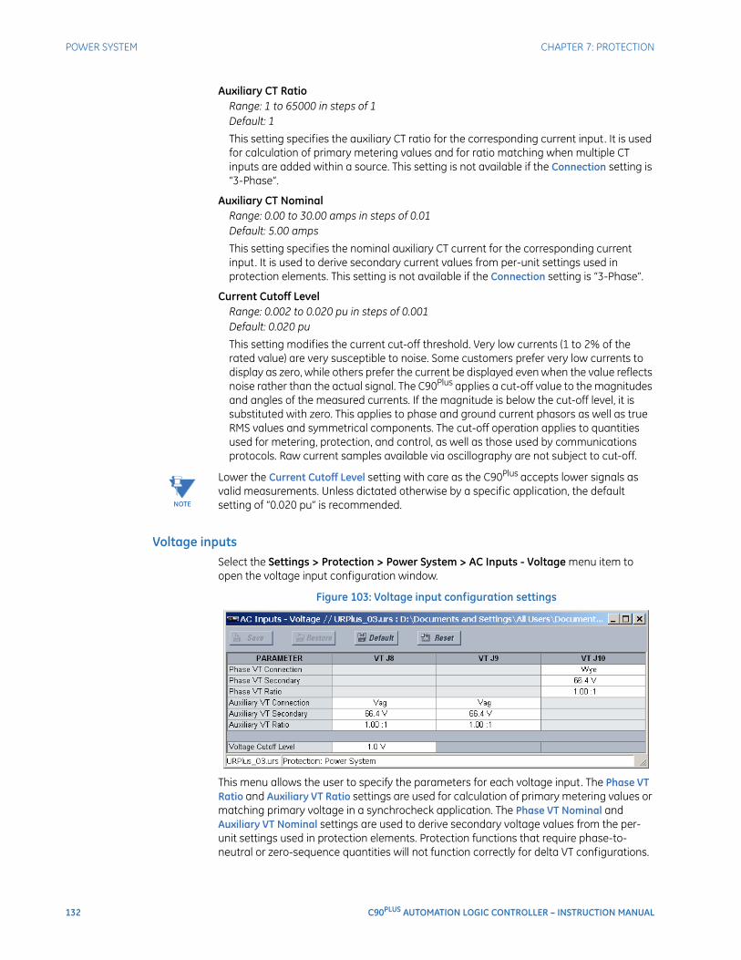
132 C90PLUS AUTOMATION LOGIC CONTROLLER – INSTRUCTION MANUAL
POWER SYSTEM CHAPTER 7: PROTECTION
Auxiliary CT RatioRange: 1 to 65000 in steps of 1Default: 1
This setting specifies the auxiliary CT ratio for the corresponding current input. It is used for calculation of primary metering values and for ratio matching when multiple CT inputs are added within a source. This setting is not available if the Connection setting is “3-Phase”.
Auxiliary CT NominalRange: 0.00 to 30.00 amps in steps of 0.01Default: 5.00 amps
This setting specifies the nominal auxiliary CT current for the corresponding current input. It is used to derive secondary current values from per-unit settings used in protection elements. This setting is not available if the Connection setting is “3-Phase”.
Current Cutoff LevelRange: 0.002 to 0.020 pu in steps of 0.001Default: 0.020 pu
This setting modifies the current cut-off threshold. Very low currents (1 to 2% of the rated value) are very susceptible to noise. Some customers prefer very low currents to display as zero, while others prefer the current be displayed even when the value reflects noise rather than the actual signal. The C90Plus applies a cut-off value to the magnitudes and angles of the measured currents. If the magnitude is below the cut-off level, it is substituted with zero. This applies to phase and ground current phasors as well as true RMS values and symmetrical components. The cut-off operation applies to quantities used for metering, protection, and control, as well as those used by communications protocols. Raw current samples available via oscillography are not subject to cut-off.
NOTE
NOTE: Lower the Current Cutoff Level setting with care as the C90Plus accepts lower signals as valid measurements. Unless dictated otherwise by a specific application, the default setting of “0.020 pu” is recommended.
Voltage inputsSelect the Settings > Protection > Power System > AC Inputs - Voltage menu item to open the voltage input configuration window.
Figure 103: Voltage input configuration settings
This menu allows the user to specify the parameters for each voltage input. The Phase VT Ratio and Auxiliary VT Ratio settings are used for calculation of primary metering values or matching primary voltage in a synchrocheck application. The Phase VT Nominal and Auxiliary VT Nominal settings are used to derive secondary voltage values from the per-unit settings used in protection elements. Protection functions that require phase-to-neutral or zero-sequence quantities will not function correctly for delta VT configurations.

CHAPTER 7: PROTECTION POWER SYSTEM
C90PLUS AUTOMATION LOGIC CONTROLLER – INSTRUCTION MANUAL 133
The following voltage input settings are available.
Phase VT ConnectionRange: Wye, DeltaDefault: Wye
This setting specifies the phase VT connection type for the corresponding voltage input. An open-delta source VT connection would be entered as “Delta”.
Phase VT RatioRange: 1.00 to 2400.00 in steps of 0.001Default: 1.00
This setting specifies the phase VT ratio for the corresponding voltage input. It is typically used for calculation of primary metering values or matching primary voltage in a synchrocheck application.
Phase VT NominalRange: 50 to 240 volts in steps of 1Default: 120 volts
This setting specifies the nominal phase VT voltage for the corresponding voltage input. It is typically used to derive secondary voltage values from the per-unit settings used in protection elements.
The typical Phase VT Nominal setting is the phase-to-phase secondary voltage appearing at the relay input terminals when nominal voltage is applied to the VT primary. For example, on a system with a 13.8 kV nominal primary voltage and with a 14400:120 V VT in a delta connection, the secondary voltage is (13800 V / 14400) × 120 = 115 V. Thus, the Phase VT Nominal setting would be 115 volts.
Auxiliary VT ConnectionRange: Vag, Vbg, Vcg, Vab, Vbc, Vca, VnDefault: Vag
This setting specifies the auxiliary VT connection type for the corresponding voltage input.
Auxiliary VT RatioRange: 1.00 to 2400.00 in steps of 0.001Default:
This setting specifies the auxiliary VT ratio for the corresponding voltage input. It is typically used for calculation of primary metering values or matching primary voltage in a synchrocheck application.
Auxiliary VT NominalRange: 50 to 240 volts in steps of 1Default: 120 volts
This setting specifies the nominal auxiliary VT voltage for the corresponding voltage input. It is typically used to derive secondary voltage values from the per-unit settings used in protection elements.
Voltage Cutoff LevelRange: 0.1 to 1.0 volts secondary in steps of 0.1Default: 1.0 volts secondary
This setting specifies the voltage cut-off threshold. Very low secondary voltage measurements (at the fractional volt level) can be affected by noise. Some customers prefer these low voltages to be displayed as zero, while others prefer the voltage to be displayed even when the value reflects noise rather than the actual signal. The C90Plus applies a cut-off value to the magnitudes and angles of the measured voltages. If the magnitude is below the cut-off level, it is substituted with zero. This operation applies to phase voltages, auxiliary voltages, and symmetrical components. The cut-off
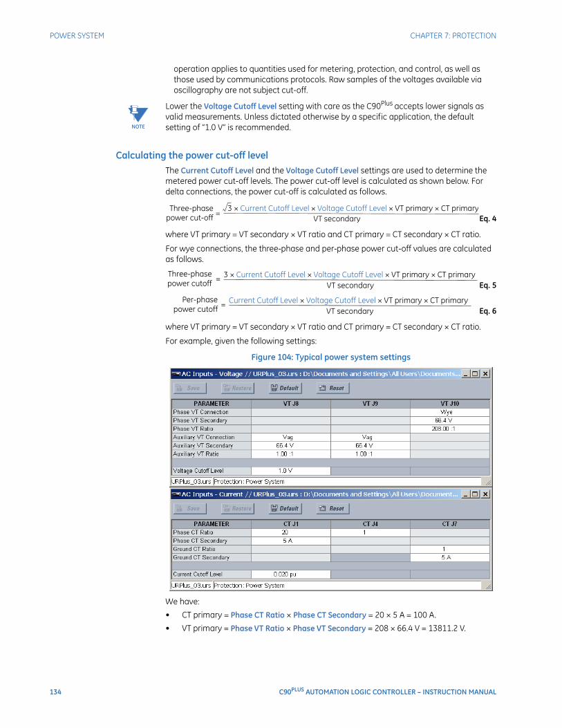
134 C90PLUS AUTOMATION LOGIC CONTROLLER – INSTRUCTION MANUAL
POWER SYSTEM CHAPTER 7: PROTECTION
operation applies to quantities used for metering, protection, and control, as well as those used by communications protocols. Raw samples of the voltages available via oscillography are not subject cut-off.
NOTE
NOTE: Lower the Voltage Cutoff Level setting with care as the C90Plus accepts lower signals as valid measurements. Unless dictated otherwise by a specific application, the default setting of “1.0 V” is recommended.
Calculating the power cut-off levelThe Current Cutoff Level and the Voltage Cutoff Level settings are used to determine the metered power cut-off levels. The power cut-off level is calculated as shown below. For delta connections, the power cut-off is calculated as follows.
Eq. 4
where VT primary = VT secondary × VT ratio and CT primary = CT secondary × CT ratio.
For wye connections, the three-phase and per-phase power cut-off values are calculated as follows.
Eq. 5
Eq. 6
where VT primary = VT secondary × VT ratio and CT primary = CT secondary × CT ratio.
For example, given the following settings:
Figure 104: Typical power system settings
We have:
• CT primary = Phase CT Ratio × Phase CT Secondary = 20 × 5 A = 100 A.
• VT primary = Phase VT Ratio × Phase VT Secondary = 208 × 66.4 V = 13811.2 V.
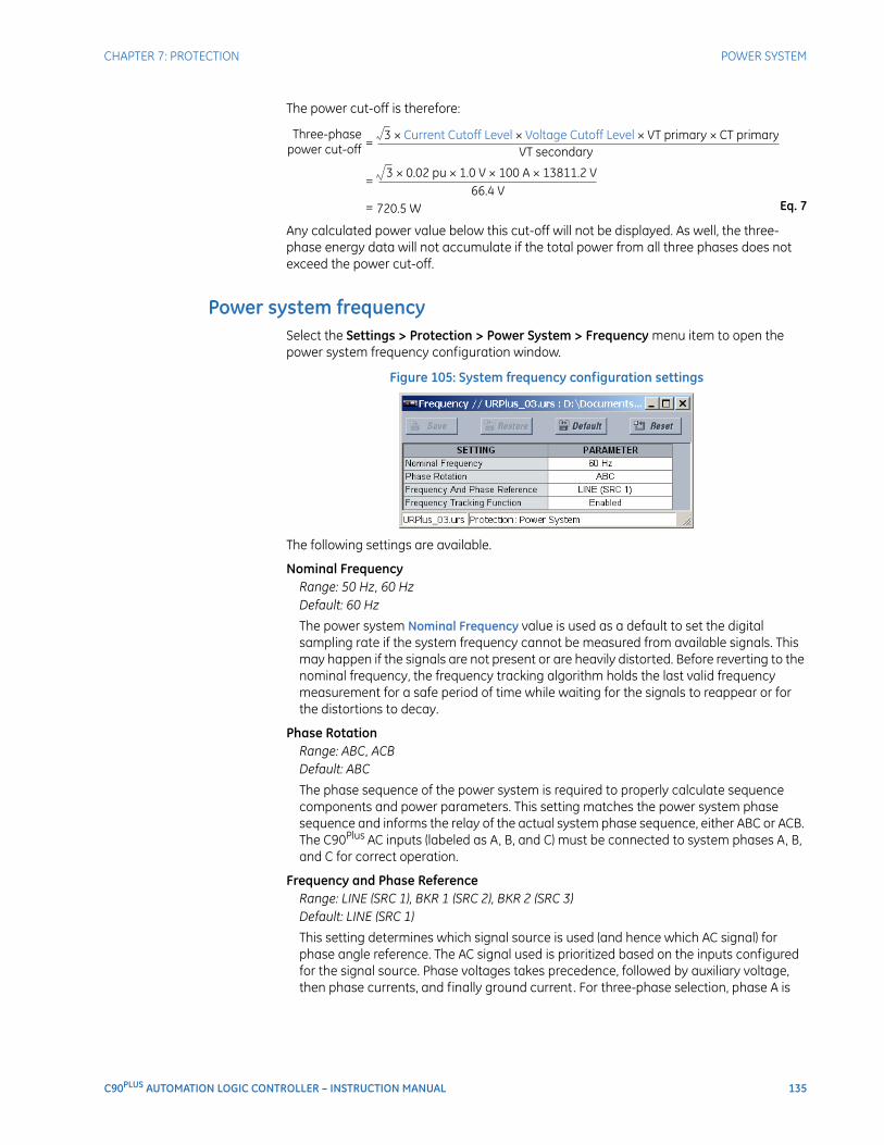
CHAPTER 7: PROTECTION POWER SYSTEM
C90PLUS AUTOMATION LOGIC CONTROLLER – INSTRUCTION MANUAL 135
The power cut-off is therefore:
Eq. 7
Any calculated power value below this cut-off will not be displayed. As well, the three-phase energy data will not accumulate if the total power from all three phases does not exceed the power cut-off.
Power system frequencySelect the Settings > Protection > Power System > Frequency menu item to open the power system frequency configuration window.
Figure 105: System frequency configuration settings
The following settings are available.
Nominal FrequencyRange: 50 Hz, 60 HzDefault: 60 Hz
The power system Nominal Frequency value is used as a default to set the digital sampling rate if the system frequency cannot be measured from available signals. This may happen if the signals are not present or are heavily distorted. Before reverting to the nominal frequency, the frequency tracking algorithm holds the last valid frequency measurement for a safe period of time while waiting for the signals to reappear or for the distortions to decay.
Phase RotationRange: ABC, ACBDefault: ABC
The phase sequence of the power system is required to properly calculate sequence components and power parameters. This setting matches the power system phase sequence and informs the relay of the actual system phase sequence, either ABC or ACB. The C90Plus AC inputs (labeled as A, B, and C) must be connected to system phases A, B, and C for correct operation.
Frequency and Phase ReferenceRange: LINE (SRC 1), BKR 1 (SRC 2), BKR 2 (SRC 3)Default: LINE (SRC 1)
This setting determines which signal source is used (and hence which AC signal) for phase angle reference. The AC signal used is prioritized based on the inputs configured for the signal source. Phase voltages takes precedence, followed by auxiliary voltage, then phase currents, and finally ground current. For three-phase selection, phase A is
136 C90PLUS AUTOMATION LOGIC CONTROLLER – INSTRUCTION MANUAL
POWER SYSTEM CHAPTER 7: PROTECTION
used for angle referencing (VANGLE_REF = VA), while the Clarke transformation of the phase signals is used for frequency metering and tracking (VFREQ = (2VA – VB –VC) / 3) for better performance during fault, open pole, and VT and CT fail conditions.
The phase reference and frequency tracking AC signals are selected based upon the source configuration, regardless of whether or not a particular signal is actually applied to the relay.
The reference signal phase angle will always display zero degrees and all other phase angles are relative to this signal. If the pre-selected reference signal is not measurable at a given time, the phase angles are not referenced.
The phase angle referencing is done via a phase locked loop, which can synchronize independent URPlus-series devices if they have the same AC signal reference. These results in very precise correlation of time tagging in the event recorder between different URPlus-series devices provided the relays have an IRIG-B connection.
Frequency TrackingRange: Disabled, EnabledDefault: Enabled
This setting should only be programmed to “Disabled” in very unusual circumstances; consult GE Digital Energy for special variable-frequency applications.
About AC sourcesThe C90Plus may be used on systems with breaker-and-a-half or ring bus configurations. In these applications, each of the two three-phase sets of individual phase currents (one associated with each breaker) can be used as an input to a breaker failure element. The sum of both breaker phase currents and 3I_0 residual currents may be required for the circuit relaying and metering functions. For a three-winding transformer application, it may be necessary to calculate watts and vars for each of the three windings, using voltage from different sets of VTs. These requirements can be satisfied with a single C90Plus IED equipped with sufficient CT and VT input channels by selecting the appropriate parameter measurement. A mechanism is provided to specify the AC parameter (or group of parameters) used as the input to the protection and control comparators and some metering elements.
Selection of the measurement parameters is partially performed by the design of a measuring element or protection/control comparator by identifying the type of parameter (fundamental frequency phasor, harmonic phasor, symmetrical component, total waveform RMS magnitude, phase-phase or phase-ground voltage, etc.) to measure. The user completes the process by selecting the instrument transformer input channels to use and some of the parameters calculated from these channels. The input parameters available include the summation of currents from multiple input channels. For the summed phase, 3I_0, and ground currents, currents from CTs with different ratios are adjusted to a single ratio before summation.
A mechanism called a source configures the routing of CT and VT input channels to measurement sub-systems. Sources, in the context of the URPlus-series relays, refer to the logical grouping of current and voltage signals such that one source contains all the signals required to measure the load or fault in a particular power apparatus. A given source may contain all or some of the following signals: three-phase currents, single-phase ground current, three-phase voltages, and an auxiliary voltage from a single VT for checking for synchronism.
To illustrate the concept of sources, as applied to current inputs only, consider the breaker-and-a-half scheme below. In this application, the current flow is indicated by the arrows. Some current flows through the upper bus bar to some other location or power equipment, and some current flows into transformer winding 1. The current into the line is the phasor sum (or difference) of the currents in CT1 and CT2 (whether the sum or
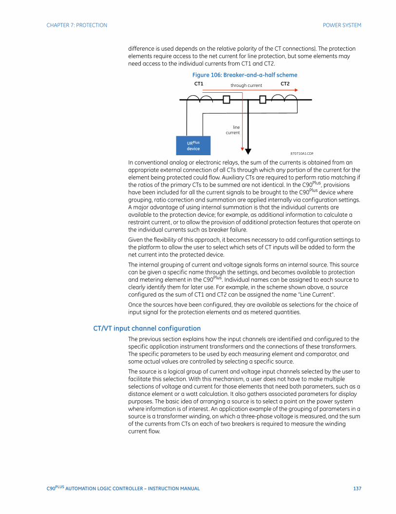
CHAPTER 7: PROTECTION POWER SYSTEM
C90PLUS AUTOMATION LOGIC CONTROLLER – INSTRUCTION MANUAL 137
difference is used depends on the relative polarity of the CT connections). The protection elements require access to the net current for line protection, but some elements may need access to the individual currents from CT1 and CT2.
Figure 106: Breaker-and-a-half scheme
In conventional analog or electronic relays, the sum of the currents is obtained from an appropriate external connection of all CTs through which any portion of the current for the element being protected could flow. Auxiliary CTs are required to perform ratio matching if the ratios of the primary CTs to be summed are not identical. In the C90Plus, provisions have been included for all the current signals to be brought to the C90Plus device where grouping, ratio correction and summation are applied internally via configuration settings. A major advantage of using internal summation is that the individual currents are available to the protection device; for example, as additional information to calculate a restraint current, or to allow the provision of additional protection features that operate on the individual currents such as breaker failure.
Given the flexibility of this approach, it becomes necessary to add configuration settings to the platform to allow the user to select which sets of CT inputs will be added to form the net current into the protected device.
The internal grouping of current and voltage signals forms an internal source. This source can be given a specific name through the settings, and becomes available to protection and metering element in the C90Plus. Individual names can be assigned to each source to clearly identify them for later use. For example, in the scheme shown above, a source configured as the sum of CT1 and CT2 can be assigned the name “Line Current”.
Once the sources have been configured, they are available as selections for the choice of input signal for the protection elements and as metered quantities.
CT/VT input channel configurationThe previous section explains how the input channels are identified and configured to the specific application instrument transformers and the connections of these transformers. The specific parameters to be used by each measuring element and comparator, and some actual values are controlled by selecting a specific source.
The source is a logical group of current and voltage input channels selected by the user to facilitate this selection. With this mechanism, a user does not have to make multiple selections of voltage and current for those elements that need both parameters, such as a distance element or a watt calculation. It also gathers associated parameters for display purposes. The basic idea of arranging a source is to select a point on the power system where information is of interest. An application example of the grouping of parameters in a source is a transformer winding, on which a three-phase voltage is measured, and the sum of the currents from CTs on each of two breakers is required to measure the winding current flow.
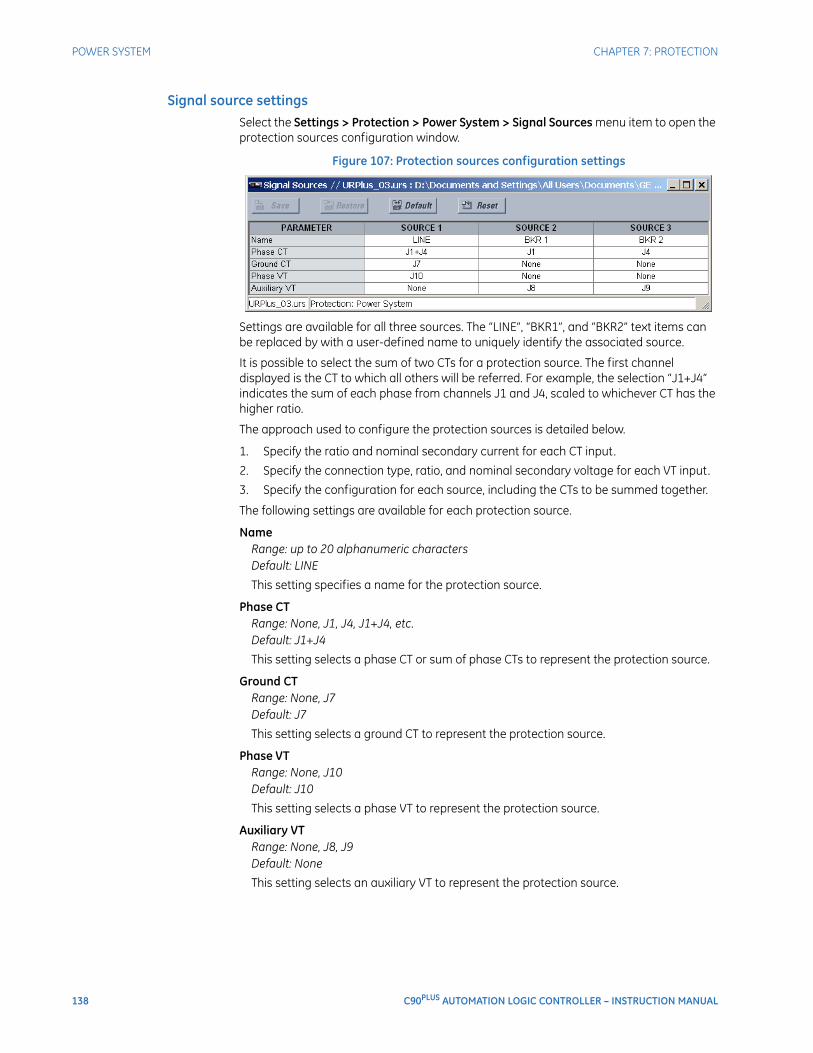
138 C90PLUS AUTOMATION LOGIC CONTROLLER – INSTRUCTION MANUAL
POWER SYSTEM CHAPTER 7: PROTECTION
Signal source settingsSelect the Settings > Protection > Power System > Signal Sources menu item to open the protection sources configuration window.
Figure 107: Protection sources configuration settings
Settings are available for all three sources. The “LINE”, “BKR1”, and “BKR2” text items can be replaced by with a user-defined name to uniquely identify the associated source.
It is possible to select the sum of two CTs for a protection source. The first channel displayed is the CT to which all others will be referred. For example, the selection “J1+J4” indicates the sum of each phase from channels J1 and J4, scaled to whichever CT has the higher ratio.
The approach used to configure the protection sources is detailed below.
1. Specify the ratio and nominal secondary current for each CT input.
2. Specify the connection type, ratio, and nominal secondary voltage for each VT input.
3. Specify the configuration for each source, including the CTs to be summed together.
The following settings are available for each protection source.
NameRange: up to 20 alphanumeric charactersDefault: LINE
This setting specifies a name for the protection source.
Phase CTRange: None, J1, J4, J1+J4, etc.Default: J1+J4
This setting selects a phase CT or sum of phase CTs to represent the protection source.
Ground CTRange: None, J7Default: J7
This setting selects a ground CT to represent the protection source.
Phase VTRange: None, J10Default: J10
This setting selects a phase VT to represent the protection source.
Auxiliary VTRange: None, J8, J9Default: None
This setting selects an auxiliary VT to represent the protection source.
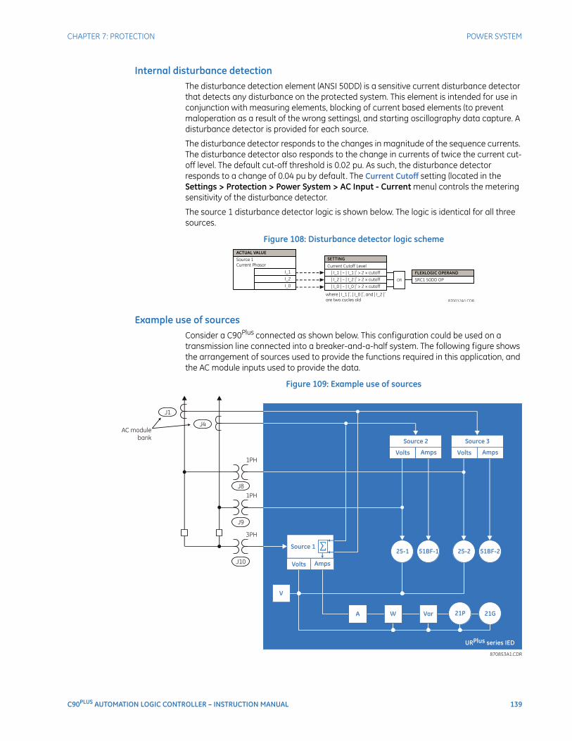
CHAPTER 7: PROTECTION POWER SYSTEM
C90PLUS AUTOMATION LOGIC CONTROLLER – INSTRUCTION MANUAL 139
Internal disturbance detectionThe disturbance detection element (ANSI 50DD) is a sensitive current disturbance detector that detects any disturbance on the protected system. This element is intended for use in conjunction with measuring elements, blocking of current based elements (to prevent maloperation as a result of the wrong settings), and starting oscillography data capture. A disturbance detector is provided for each source.
The disturbance detector responds to the changes in magnitude of the sequence currents. The disturbance detector also responds to the change in currents of twice the current cut-off level. The default cut-off threshold is 0.02 pu. As such, the disturbance detector responds to a change of 0.04 pu by default. The Current Cutoff setting (located in the Settings > Protection > Power System > AC Input - Current menu) controls the metering sensitivity of the disturbance detector.
The source 1 disturbance detector logic is shown below. The logic is identical for all three sources.
Figure 108: Disturbance detector logic scheme
Example use of sourcesConsider a C90Plus connected as shown below. This configuration could be used on a transmission line connected into a breaker-and-a-half system. The following figure shows the arrangement of sources used to provide the functions required in this application, and the AC module inputs used to provide the data.
Figure 109: Example use of sources
140 C90PLUS AUTOMATION LOGIC CONTROLLER – INSTRUCTION MANUAL
GROUPED PROTECTION ELEMENTS CHAPTER 7: PROTECTION
Grouped protection elementsEach protection element can be assigned up to six different sets of settings according to setting group designations 1 to 6. The performance of these elements is defined by the active setting group at a given time. Multiple setting groups allow the user to conveniently change protection settings for different operating situations (for example, altered power system configuration or season of the year). The active setting group can be preset or selected via the Settings > Protection > Control > Setting Groups menu item.
Current elementsThe current element settings are described in this section.
Overview of time overcurrent curvesThe inverse time overcurrent curves used by the time overcurrent elements are the IEEE, IEC, GE Type IAC, and I2t standard curve shapes. This allows for simplified coordination with downstream devices. If however, none of these curve shapes is adequate, FlexCurves™ may be used to customize the inverse time curve characteristics. The definite time curve is also an option that may be appropriate if only simple protection is required.
The following overcurrent curve types are available.
• IEEE Extremely Inverse.
• IEEE Very Inverse.
• IEEE Moderately Inverse.
• IEC Curve A (BS142).
• IEC Curve B (BS142).
• IEC Curve C (BS142).
• IAC Extremely Inverse.
• IAC Very Inverse.
• IAC Inverse.
• IAC Short Inverse.
• I2t.
• FlexCurves™ A, B, C, and D.
• Recloser curves.
• Definite Time.
A multiplier (time dial) setting allows selection of a multiple of the base curve shape (where the time dial multiplier = 1) with the curve shape setting. Unlike the electromechanical time dial equivalent, operate times are directly proportional to the time multiplier setting value. For example, all times for a multiplier of 10 are 10 times the multiplier 1 or base curve values. Setting the multiplier to zero results in an instantaneous response to all current levels above pickup.
Time overcurrent time calculations are made with an internal energy capacity memory variable. When this variable indicates that the energy capacity has reached 100%, a time overcurrent element will operate. If less than 100% energy capacity is accumulated in this variable and the current falls below the dropout threshold of 97 to 98% of the pickup value, the variable must be reduced. Two methods of this resetting operation are available: instantaneous and timed. The instantaneous method is intended for applications with other relays, such as most static relays, which set the energy capacity directly to zero when the current falls below the reset threshold. The timed method can be used where the relay must coordinate with electromechanical relays.
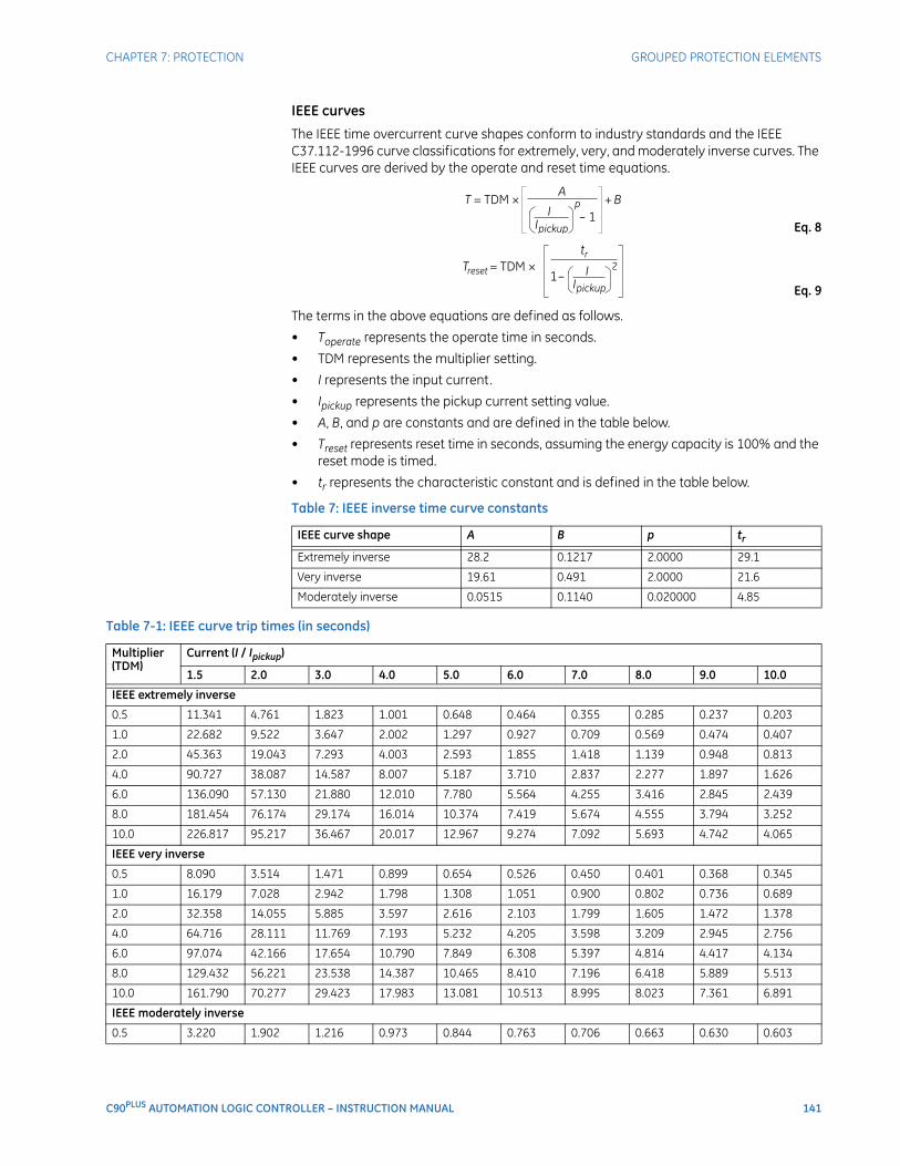
CHAPTER 7: PROTECTION GROUPED PROTECTION ELEMENTS
C90PLUS AUTOMATION LOGIC CONTROLLER – INSTRUCTION MANUAL 141
IEEE curves
The IEEE time overcurrent curve shapes conform to industry standards and the IEEE C37.112-1996 curve classifications for extremely, very, and moderately inverse curves. The IEEE curves are derived by the operate and reset time equations.
Eq. 8
Eq. 9
The terms in the above equations are defined as follows.
• Toperate represents the operate time in seconds.
• TDM represents the multiplier setting.
• I represents the input current.
• Ipickup represents the pickup current setting value.
• A, B, and p are constants and are defined in the table below.
• Treset represents reset time in seconds, assuming the energy capacity is 100% and the reset mode is timed.
• tr represents the characteristic constant and is defined in the table below.
Table 7: IEEE inverse time curve constants
Table 7-1: IEEE curve trip times (in seconds)
IEEE curve shape A B p tr
Extremely inverse 28.2 0.1217 2.0000 29.1
Very inverse 19.61 0.491 2.0000 21.6
Moderately inverse 0.0515 0.1140 0.020000 4.85
Multiplier (TDM)
Current (I / Ipickup)
1.5 2.0 3.0 4.0 5.0 6.0 7.0 8.0 9.0 10.0
IEEE extremely inverse
0.5 11.341 4.761 1.823 1.001 0.648 0.464 0.355 0.285 0.237 0.203
1.0 22.682 9.522 3.647 2.002 1.297 0.927 0.709 0.569 0.474 0.407
2.0 45.363 19.043 7.293 4.003 2.593 1.855 1.418 1.139 0.948 0.813
4.0 90.727 38.087 14.587 8.007 5.187 3.710 2.837 2.277 1.897 1.626
6.0 136.090 57.130 21.880 12.010 7.780 5.564 4.255 3.416 2.845 2.439
8.0 181.454 76.174 29.174 16.014 10.374 7.419 5.674 4.555 3.794 3.252
10.0 226.817 95.217 36.467 20.017 12.967 9.274 7.092 5.693 4.742 4.065
IEEE very inverse
0.5 8.090 3.514 1.471 0.899 0.654 0.526 0.450 0.401 0.368 0.345
1.0 16.179 7.028 2.942 1.798 1.308 1.051 0.900 0.802 0.736 0.689
2.0 32.358 14.055 5.885 3.597 2.616 2.103 1.799 1.605 1.472 1.378
4.0 64.716 28.111 11.769 7.193 5.232 4.205 3.598 3.209 2.945 2.756
6.0 97.074 42.166 17.654 10.790 7.849 6.308 5.397 4.814 4.417 4.134
8.0 129.432 56.221 23.538 14.387 10.465 8.410 7.196 6.418 5.889 5.513
10.0 161.790 70.277 29.423 17.983 13.081 10.513 8.995 8.023 7.361 6.891
IEEE moderately inverse
0.5 3.220 1.902 1.216 0.973 0.844 0.763 0.706 0.663 0.630 0.603
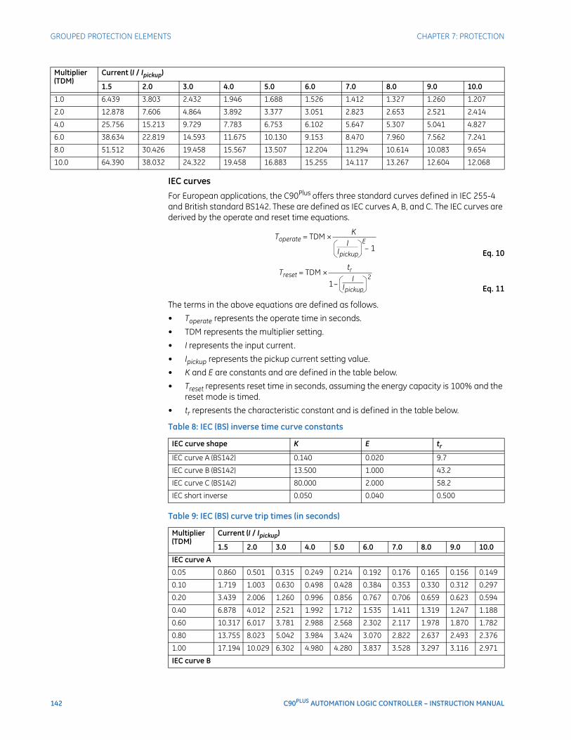
142 C90PLUS AUTOMATION LOGIC CONTROLLER – INSTRUCTION MANUAL
GROUPED PROTECTION ELEMENTS CHAPTER 7: PROTECTION
IEC curves
For European applications, the C90Plus offers three standard curves defined in IEC 255-4 and British standard BS142. These are defined as IEC curves A, B, and C. The IEC curves are derived by the operate and reset time equations.
Eq. 10
Eq. 11
The terms in the above equations are defined as follows.
• Toperate represents the operate time in seconds.
• TDM represents the multiplier setting.
• I represents the input current.
• Ipickup represents the pickup current setting value.
• K and E are constants and are defined in the table below.
• Treset represents reset time in seconds, assuming the energy capacity is 100% and the reset mode is timed.
• tr represents the characteristic constant and is defined in the table below.
Table 8: IEC (BS) inverse time curve constants
Table 9: IEC (BS) curve trip times (in seconds)
1.0 6.439 3.803 2.432 1.946 1.688 1.526 1.412 1.327 1.260 1.207
2.0 12.878 7.606 4.864 3.892 3.377 3.051 2.823 2.653 2.521 2.414
4.0 25.756 15.213 9.729 7.783 6.753 6.102 5.647 5.307 5.041 4.827
6.0 38.634 22.819 14.593 11.675 10.130 9.153 8.470 7.960 7.562 7.241
8.0 51.512 30.426 19.458 15.567 13.507 12.204 11.294 10.614 10.083 9.654
10.0 64.390 38.032 24.322 19.458 16.883 15.255 14.117 13.267 12.604 12.068
Multiplier (TDM)
Current (I / Ipickup)
1.5 2.0 3.0 4.0 5.0 6.0 7.0 8.0 9.0 10.0
IEC curve shape K E tr
IEC curve A (BS142) 0.140 0.020 9.7
IEC curve B (BS142) 13.500 1.000 43.2
IEC curve C (BS142) 80.000 2.000 58.2
IEC short inverse 0.050 0.040 0.500
Multiplier (TDM)
Current (I / Ipickup)
1.5 2.0 3.0 4.0 5.0 6.0 7.0 8.0 9.0 10.0
IEC curve A
0.05 0.860 0.501 0.315 0.249 0.214 0.192 0.176 0.165 0.156 0.149
0.10 1.719 1.003 0.630 0.498 0.428 0.384 0.353 0.330 0.312 0.297
0.20 3.439 2.006 1.260 0.996 0.856 0.767 0.706 0.659 0.623 0.594
0.40 6.878 4.012 2.521 1.992 1.712 1.535 1.411 1.319 1.247 1.188
0.60 10.317 6.017 3.781 2.988 2.568 2.302 2.117 1.978 1.870 1.782
0.80 13.755 8.023 5.042 3.984 3.424 3.070 2.822 2.637 2.493 2.376
1.00 17.194 10.029 6.302 4.980 4.280 3.837 3.528 3.297 3.116 2.971
IEC curve B
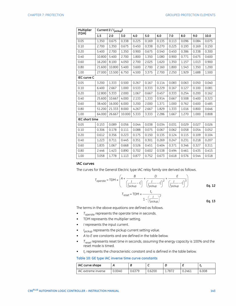
CHAPTER 7: PROTECTION GROUPED PROTECTION ELEMENTS
C90PLUS AUTOMATION LOGIC CONTROLLER – INSTRUCTION MANUAL 143
IAC curves
The curves for the General Electric type IAC relay family are derived as follows.
Eq. 12
Eq. 13
The terms in the above equations are defined as follows.
• Toperate represents the operate time in seconds.
• TDM represents the multiplier setting.
• I represents the input current.
• Ipickup represents the pickup current setting value.
• A to E are constants and are defined in the table below.
• Treset represents reset time in seconds, assuming the energy capacity is 100% and the reset mode is timed.
• tr represents the characteristic constant and is defined in the table below.
Table 10: GE type IAC inverse time curve constants
0.05 1.350 0.675 0.338 0.225 0.169 0.135 0.113 0.096 0.084 0.075
0.10 2.700 1.350 0.675 0.450 0.338 0.270 0.225 0.193 0.169 0.150
0.20 5.400 2.700 1.350 0.900 0.675 0.540 0.450 0.386 0.338 0.300
0.40 10.800 5.400 2.700 1.800 1.350 1.080 0.900 0.771 0.675 0.600
0.60 16.200 8.100 4.050 2.700 2.025 1.620 1.350 1.157 1.013 0.900
0.80 21.600 10.800 5.400 3.600 2.700 2.160 1.800 1.543 1.350 1.200
1.00 27.000 13.500 6.750 4.500 3.375 2.700 2.250 1.929 1.688 1.500
IEC curve C
0.05 3.200 1.333 0.500 0.267 0.167 0.114 0.083 0.063 0.050 0.040
0.10 6.400 2.667 1.000 0.533 0.333 0.229 0.167 0.127 0.100 0.081
0.20 12.800 5.333 2.000 1.067 0.667 0.457 0.333 0.254 0.200 0.162
0.40 25.600 10.667 4.000 2.133 1.333 0.914 0.667 0.508 0.400 0.323
0.60 38.400 16.000 6.000 3.200 2.000 1.371 1.000 0.762 0.600 0.485
0.80 51.200 21.333 8.000 4.267 2.667 1.829 1.333 1.016 0.800 0.646
1.00 64.000 26.667 10.000 5.333 3.333 2.286 1.667 1.270 1.000 0.808
IEC short time
0.05 0.153 0.089 0.056 0.044 0.038 0.034 0.031 0.029 0.027 0.026
0.10 0.306 0.178 0.111 0.088 0.075 0.067 0.062 0.058 0.054 0.052
0.20 0.612 0.356 0.223 0.175 0.150 0.135 0.124 0.115 0.109 0.104
0.40 1.223 0.711 0.445 0.351 0.301 0.269 0.247 0.231 0.218 0.207
0.60 1.835 1.067 0.668 0.526 0.451 0.404 0.371 0.346 0.327 0.311
0.80 2.446 1.423 0.890 0.702 0.602 0.538 0.494 0.461 0.435 0.415
1.00 3.058 1.778 1.113 0.877 0.752 0.673 0.618 0.576 0.544 0.518
IAC curve shape A B C D E tr
IAC extreme inverse 0.0040 0.6379 0.6200 1.7872 0.2461 6.008
Multiplier (TDM)
Current (I / Ipickup)
1.5 2.0 3.0 4.0 5.0 6.0 7.0 8.0 9.0 10.0
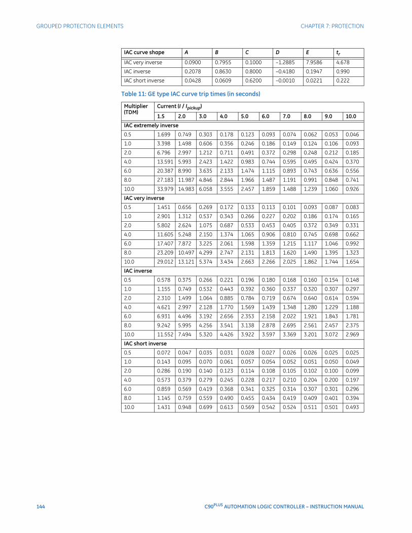
144 C90PLUS AUTOMATION LOGIC CONTROLLER – INSTRUCTION MANUAL
GROUPED PROTECTION ELEMENTS CHAPTER 7: PROTECTION
Table 11: GE type IAC curve trip times (in seconds)
IAC very inverse 0.0900 0.7955 0.1000 –1.2885 7.9586 4.678
IAC inverse 0.2078 0.8630 0.8000 –0.4180 0.1947 0.990
IAC short inverse 0.0428 0.0609 0.6200 –0.0010 0.0221 0.222
Multiplier (TDM)
Current (I / Ipickup)
1.5 2.0 3.0 4.0 5.0 6.0 7.0 8.0 9.0 10.0
IAC extremely inverse
0.5 1.699 0.749 0.303 0.178 0.123 0.093 0.074 0.062 0.053 0.046
1.0 3.398 1.498 0.606 0.356 0.246 0.186 0.149 0.124 0.106 0.093
2.0 6.796 2.997 1.212 0.711 0.491 0.372 0.298 0.248 0.212 0.185
4.0 13.591 5.993 2.423 1.422 0.983 0.744 0.595 0.495 0.424 0.370
6.0 20.387 8.990 3.635 2.133 1.474 1.115 0.893 0.743 0.636 0.556
8.0 27.183 11.987 4.846 2.844 1.966 1.487 1.191 0.991 0.848 0.741
10.0 33.979 14.983 6.058 3.555 2.457 1.859 1.488 1.239 1.060 0.926
IAC very inverse
0.5 1.451 0.656 0.269 0.172 0.133 0.113 0.101 0.093 0.087 0.083
1.0 2.901 1.312 0.537 0.343 0.266 0.227 0.202 0.186 0.174 0.165
2.0 5.802 2.624 1.075 0.687 0.533 0.453 0.405 0.372 0.349 0.331
4.0 11.605 5.248 2.150 1.374 1.065 0.906 0.810 0.745 0.698 0.662
6.0 17.407 7.872 3.225 2.061 1.598 1.359 1.215 1.117 1.046 0.992
8.0 23.209 10.497 4.299 2.747 2.131 1.813 1.620 1.490 1.395 1.323
10.0 29.012 13.121 5.374 3.434 2.663 2.266 2.025 1.862 1.744 1.654
IAC inverse
0.5 0.578 0.375 0.266 0.221 0.196 0.180 0.168 0.160 0.154 0.148
1.0 1.155 0.749 0.532 0.443 0.392 0.360 0.337 0.320 0.307 0.297
2.0 2.310 1.499 1.064 0.885 0.784 0.719 0.674 0.640 0.614 0.594
4.0 4.621 2.997 2.128 1.770 1.569 1.439 1.348 1.280 1.229 1.188
6.0 6.931 4.496 3.192 2.656 2.353 2.158 2.022 1.921 1.843 1.781
8.0 9.242 5.995 4.256 3.541 3.138 2.878 2.695 2.561 2.457 2.375
10.0 11.552 7.494 5.320 4.426 3.922 3.597 3.369 3.201 3.072 2.969
IAC short inverse
0.5 0.072 0.047 0.035 0.031 0.028 0.027 0.026 0.026 0.025 0.025
1.0 0.143 0.095 0.070 0.061 0.057 0.054 0.052 0.051 0.050 0.049
2.0 0.286 0.190 0.140 0.123 0.114 0.108 0.105 0.102 0.100 0.099
4.0 0.573 0.379 0.279 0.245 0.228 0.217 0.210 0.204 0.200 0.197
6.0 0.859 0.569 0.419 0.368 0.341 0.325 0.314 0.307 0.301 0.296
8.0 1.145 0.759 0.559 0.490 0.455 0.434 0.419 0.409 0.401 0.394
10.0 1.431 0.948 0.699 0.613 0.569 0.542 0.524 0.511 0.501 0.493
IAC curve shape A B C D E tr
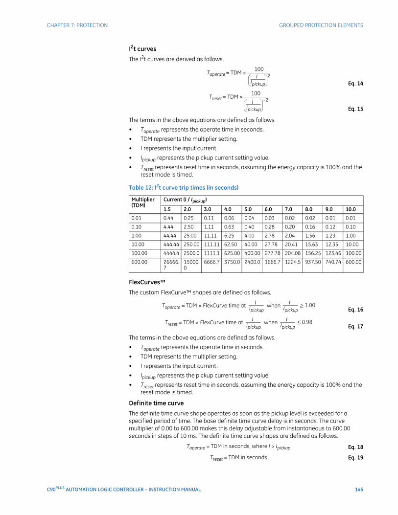
CHAPTER 7: PROTECTION GROUPED PROTECTION ELEMENTS
C90PLUS AUTOMATION LOGIC CONTROLLER – INSTRUCTION MANUAL 145
I2t curves
The I2t curves are derived as follows.
Eq. 14
Eq. 15
The terms in the above equations are defined as follows.
• Toperate represents the operate time in seconds.
• TDM represents the multiplier setting.
• I represents the input current.
• Ipickup represents the pickup current setting value.
• Treset represents reset time in seconds, assuming the energy capacity is 100% and the reset mode is timed.
Table 12: I2t curve trip times (in seconds)
FlexCurves™
The custom FlexCurve™ shapes are defined as follows.
Eq. 16
Eq. 17
The terms in the above equations are defined as follows.
• Toperate represents the operate time in seconds.
• TDM represents the multiplier setting.
• I represents the input current.
• Ipickup represents the pickup current setting value.
• Treset represents reset time in seconds, assuming the energy capacity is 100% and the reset mode is timed.
Definite time curve
The definite time curve shape operates as soon as the pickup level is exceeded for a specified period of time. The base definite time curve delay is in seconds. The curve multiplier of 0.00 to 600.00 makes this delay adjustable from instantaneous to 600.00 seconds in steps of 10 ms. The definite time curve shapes are defined as follows.
Eq. 18
Eq. 19
Multiplier (TDM)
Current (I / Ipickup)
1.5 2.0 3.0 4.0 5.0 6.0 7.0 8.0 9.0 10.0
0.01 0.44 0.25 0.11 0.06 0.04 0.03 0.02 0.02 0.01 0.01
0.10 4.44 2.50 1.11 0.63 0.40 0.28 0.20 0.16 0.12 0.10
1.00 44.44 25.00 11.11 6.25 4.00 2.78 2.04 1.56 1.23 1.00
10.00 444.44 250.00 111.11 62.50 40.00 27.78 20.41 15.63 12.35 10.00
100.00 4444.4 2500.0 1111.1 625.00 400.00 277.78 204.08 156.25 123.46 100.00
600.00 26666.7
15000.0
6666.7 3750.0 2400.0 1666.7 1224.5 937.50 740.74 600.00
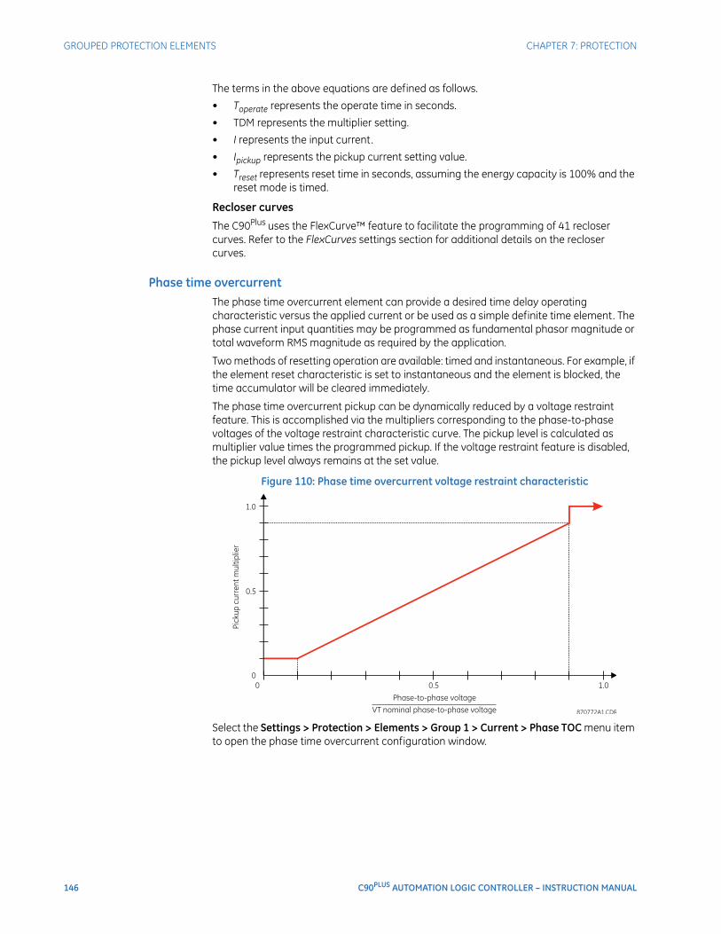
146 C90PLUS AUTOMATION LOGIC CONTROLLER – INSTRUCTION MANUAL
GROUPED PROTECTION ELEMENTS CHAPTER 7: PROTECTION
The terms in the above equations are defined as follows.
• Toperate represents the operate time in seconds.
• TDM represents the multiplier setting.
• I represents the input current.
• Ipickup represents the pickup current setting value.
• Treset represents reset time in seconds, assuming the energy capacity is 100% and the reset mode is timed.
Recloser curves
The C90Plus uses the FlexCurve™ feature to facilitate the programming of 41 recloser curves. Refer to the FlexCurves settings section for additional details on the recloser curves.
Phase time overcurrentThe phase time overcurrent element can provide a desired time delay operating characteristic versus the applied current or be used as a simple definite time element. The phase current input quantities may be programmed as fundamental phasor magnitude or total waveform RMS magnitude as required by the application.
Two methods of resetting operation are available: timed and instantaneous. For example, if the element reset characteristic is set to instantaneous and the element is blocked, the time accumulator will be cleared immediately.
The phase time overcurrent pickup can be dynamically reduced by a voltage restraint feature. This is accomplished via the multipliers corresponding to the phase-to-phase voltages of the voltage restraint characteristic curve. The pickup level is calculated as multiplier value times the programmed pickup. If the voltage restraint feature is disabled, the pickup level always remains at the set value.
Figure 110: Phase time overcurrent voltage restraint characteristic
Select the Settings > Protection > Elements > Group 1 > Current > Phase TOC menu item to open the phase time overcurrent configuration window.
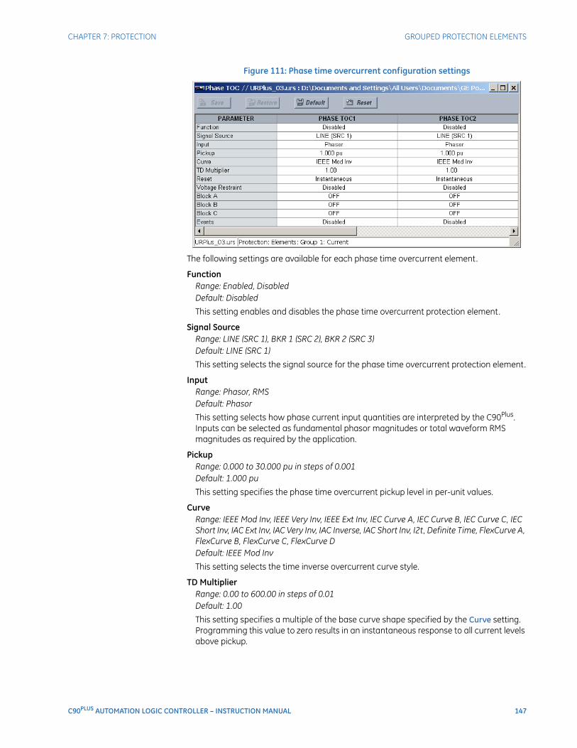
CHAPTER 7: PROTECTION GROUPED PROTECTION ELEMENTS
C90PLUS AUTOMATION LOGIC CONTROLLER – INSTRUCTION MANUAL 147
Figure 111: Phase time overcurrent configuration settings
The following settings are available for each phase time overcurrent element.
FunctionRange: Enabled, DisabledDefault: Disabled
This setting enables and disables the phase time overcurrent protection element.
Signal SourceRange: LINE (SRC 1), BKR 1 (SRC 2), BKR 2 (SRC 3)Default: LINE (SRC 1)
This setting selects the signal source for the phase time overcurrent protection element.
InputRange: Phasor, RMSDefault: Phasor
This setting selects how phase current input quantities are interpreted by the C90Plus. Inputs can be selected as fundamental phasor magnitudes or total waveform RMS magnitudes as required by the application.
PickupRange: 0.000 to 30.000 pu in steps of 0.001Default: 1.000 pu
This setting specifies the phase time overcurrent pickup level in per-unit values.
CurveRange: IEEE Mod Inv, IEEE Very Inv, IEEE Ext Inv, IEC Curve A, IEC Curve B, IEC Curve C, IEC Short Inv, IAC Ext Inv, IAC Very Inv, IAC Inverse, IAC Short Inv, I2t, Definite Time, FlexCurve A, FlexCurve B, FlexCurve C, FlexCurve DDefault: IEEE Mod Inv
This setting selects the time inverse overcurrent curve style.
TD MultiplierRange: 0.00 to 600.00 in steps of 0.01Default: 1.00
This setting specifies a multiple of the base curve shape specified by the Curve setting. Programming this value to zero results in an instantaneous response to all current levels above pickup.

148 C90PLUS AUTOMATION LOGIC CONTROLLER – INSTRUCTION MANUAL
GROUPED PROTECTION ELEMENTS CHAPTER 7: PROTECTION
ResetRange: Instantaneous, TimedDefault: Instantaneous
The “Instantaneous” reset method is intended for applications with other relays, such as most static relays, which set the energy capacity directly to zero when the current falls below the reset threshold. The “Timed” reset method can be used where the relay must coordinate with electromechanical relays.
Voltage RestraintRange: Enabled, DisabledDefault:
This setting enables and disabled the phase time overcurrent voltage restraint feature.
Block ARange: any FlexLogic™ operand or shared operandDefault: Off
Assertion of the operand assigned to this setting blocks phase A of the phase time overcurrent element.
Block BRange: any FlexLogic™ operand or shared operandDefault: Off
Assertion of the operand assigned to this setting blocks phase B of the phase time overcurrent element.
Block CRange: any FlexLogic™ operand or shared operandDefault: Off
Assertion of the operand assigned to this setting blocks phase C of the phase time overcurrent element.
EventsRange: Enabled, DisabledDefault: varies with URPlus-series model; refer to the EnerVista URPlus Setup software
This setting enables and disables the logging of phase time overcurrent events in the sequence of events recorder.
The logic for the phase time overcurrent 1 element is shown below. The logic is identical for all phase instantaneous overcurrent elements.
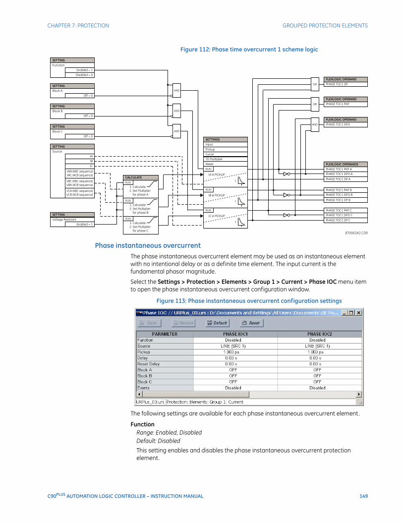
CHAPTER 7: PROTECTION GROUPED PROTECTION ELEMENTS
C90PLUS AUTOMATION LOGIC CONTROLLER – INSTRUCTION MANUAL 149
Figure 112: Phase time overcurrent 1 scheme logic
Phase instantaneous overcurrentThe phase instantaneous overcurrent element may be used as an instantaneous element with no intentional delay or as a definite time element. The input current is the fundamental phasor magnitude.
Select the Settings > Protection > Elements > Group 1 > Current > Phase IOC menu item to open the phase instantaneous overcurrent configuration window.
Figure 113: Phase instantaneous overcurrent configuration settings
The following settings are available for each phase instantaneous overcurrent element.
FunctionRange: Enabled, DisabledDefault: Disabled
This setting enables and disables the phase instantaneous overcurrent protection element.
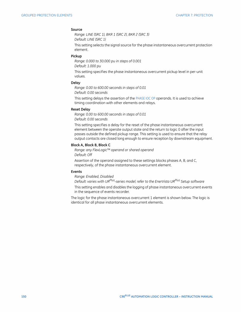
150 C90PLUS AUTOMATION LOGIC CONTROLLER – INSTRUCTION MANUAL
GROUPED PROTECTION ELEMENTS CHAPTER 7: PROTECTION
SourceRange: LINE (SRC 1), BKR 1 (SRC 2), BKR 2 (SRC 3)Default: LINE (SRC 1)
This setting selects the signal source for the phase instantaneous overcurrent protection element.
PickupRange: 0.000 to 30.000 pu in steps of 0.001Default: 1.000 pu
This setting specifies the phase instantaneous overcurrent pickup level in per-unit values.
DelayRange: 0.00 to 600.00 seconds in steps of 0.01Default: 0.00 seconds
This setting delays the assertion of the PHASE IOC OP operands. It is used to achieve timing coordination with other elements and relays.
Reset DelayRange: 0.00 to 600.00 seconds in steps of 0.01Default: 0.00 seconds
This setting specifies a delay for the reset of the phase instantaneous overcurrent element between the operate output state and the return to logic 0 after the input passes outside the defined pickup range. This setting is used to ensure that the relay output contacts are closed long enough to ensure reception by downstream equipment.
Block A, Block B, Block CRange: any FlexLogic™ operand or shared operandDefault: Off
Assertion of the operand assigned to these settings blocks phases A, B, and C, respectively, of the phase instantaneous overcurrent element.
EventsRange: Enabled, DisabledDefault: varies with URPlus-series model; refer to the EnerVista URPlus Setup software
This setting enables and disables the logging of phase instantaneous overcurrent events in the sequence of events recorder.
The logic for the phase instantaneous overcurrent 1 element is shown below. The logic is identical for all phase instantaneous overcurrent elements.
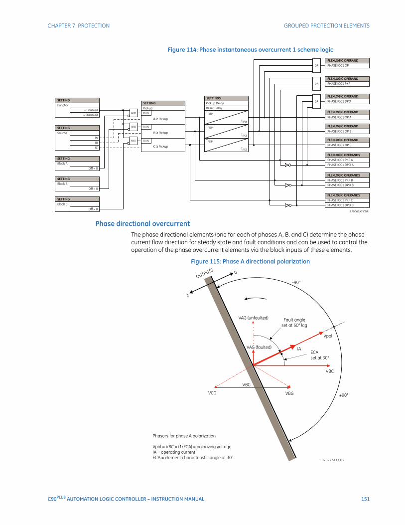
CHAPTER 7: PROTECTION GROUPED PROTECTION ELEMENTS
C90PLUS AUTOMATION LOGIC CONTROLLER – INSTRUCTION MANUAL 151
Figure 114: Phase instantaneous overcurrent 1 scheme logic
Phase directional overcurrentThe phase directional elements (one for each of phases A, B, and C) determine the phase current flow direction for steady state and fault conditions and can be used to control the operation of the phase overcurrent elements via the block inputs of these elements.
Figure 115: Phase A directional polarization

152 C90PLUS AUTOMATION LOGIC CONTROLLER – INSTRUCTION MANUAL
GROUPED PROTECTION ELEMENTS CHAPTER 7: PROTECTION
The phase directional overcurrent element is intended to apply a block signal to an overcurrent element to prevent an operation when current is flowing in a particular direction. The direction of current flow is determined by measuring the phase angle between the current from the phase CTs and the line-line voltage from the VTs, based on the 90° or quadrature connection. If there is a requirement to supervise overcurrent elements for flows in opposite directions, such as can happen through a bus-tie breaker, two phase directional elements should be programmed with opposite element characteristic angle (ECA) settings.
To increase security for three phase faults very close to the VTs used to measure the polarizing voltage, a voltage memory feature is incorporated. This feature stores the polarizing voltage the moment before the voltage collapses, and uses it to determine direction. The voltage memory remains valid for one second after the voltage has collapsed.
The main component of the phase directional element is the phase angle comparator with two inputs: the operating signal (phase current) and the polarizing signal (the line voltage, shifted in the leading direction by the characteristic angle, ECA).
The following table shows the operating and polarizing signals used for phase directional control.
Table 13: Phase directional overcurrent operating and polarizing signals
When the phase directional overcurrent element is disabled or the operating current is below 5% × CT nominal, the element output is logic 0.
When the phase directional overcurrent element is enabled, the operating current is above 5% × CT nominal, and the polarizing voltage is above the Voltage Cut Off Level setting value, the element output is dependent on the phase angle between the operating and polarizing signals. The element output is logic 0 when the operating current is within polarizing voltage ±90°; for all other angles, the element output is logic 1.
Once the voltage memory has expired, the phase overcurrent elements under directional control can be set to block or trip on overcurrent. When the Block When Voltage Memory Expires value is“Yes”, the directional element will block the operation of any phase overcurrent element under directional control when voltage memory expires. When the Block When Voltage Memory Expires value is “No”, the directional element allows tripping of phase overcurrent elements under directional control when voltage memory expires.
In all cases, directional blocking will be permitted to resume when the polarizing voltage becomes greater than the polarizing voltage threshold.
NOTE
NOTE: The phase directional element responds to the forward load current. In the case of a following reverse fault, the element needs some time – in the order of 8 ms – to establish a blocking signal. Some protection elements such as instantaneous overcurrent may respond to reverse faults before the blocking signal is established. Therefore, a coordination time of at least 10 ms must be added to all the instantaneous protection elements under the supervision of the phase directional element. If current reversal is of a concern, a longer delay – in the order of 20 ms – may be needed.
Select the Settings > Protection > Elements > Group 1 > Current > Phase Directional OC menu item to open the phase directional overcurrent configuration window.
Phase Operating signal Polarizing signal
ABC phase sequence ACB phase sequence
A angle of IA angle of VBC × (1∠ECA) angle of VCB × (1∠ECA)
B angle of IB angle of VCA × (1∠ECA) angle of VAC × (1∠ECA)
C angle of IC angle of VAB × (1∠ECA) angle of VBA × (1∠ECA)
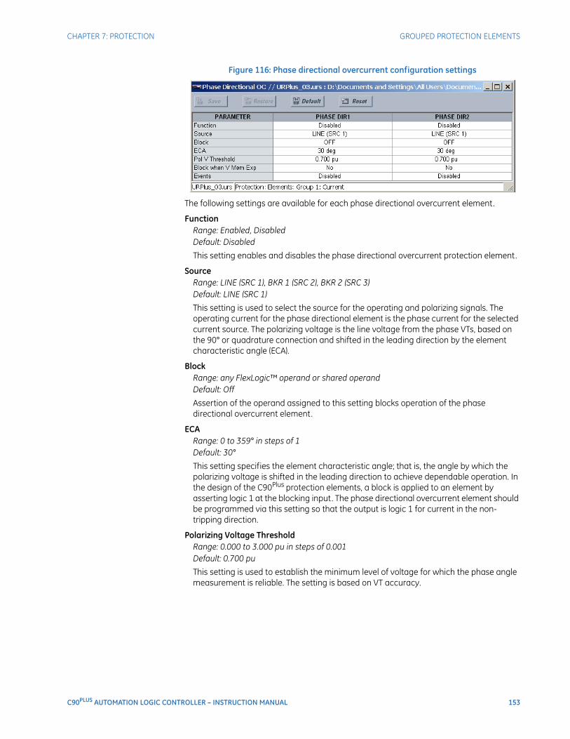
CHAPTER 7: PROTECTION GROUPED PROTECTION ELEMENTS
C90PLUS AUTOMATION LOGIC CONTROLLER – INSTRUCTION MANUAL 153
Figure 116: Phase directional overcurrent configuration settings
The following settings are available for each phase directional overcurrent element.
FunctionRange: Enabled, DisabledDefault: Disabled
This setting enables and disables the phase directional overcurrent protection element.
SourceRange: LINE (SRC 1), BKR 1 (SRC 2), BKR 2 (SRC 3)Default: LINE (SRC 1)
This setting is used to select the source for the operating and polarizing signals. The operating current for the phase directional element is the phase current for the selected current source. The polarizing voltage is the line voltage from the phase VTs, based on the 90° or quadrature connection and shifted in the leading direction by the element characteristic angle (ECA).
BlockRange: any FlexLogic™ operand or shared operandDefault: Off
Assertion of the operand assigned to this setting blocks operation of the phase directional overcurrent element.
ECARange: 0 to 359° in steps of 1Default: 30°
This setting specifies the element characteristic angle; that is, the angle by which the polarizing voltage is shifted in the leading direction to achieve dependable operation. In the design of the C90Plus protection elements, a block is applied to an element by asserting logic 1 at the blocking input. The phase directional overcurrent element should be programmed via this setting so that the output is logic 1 for current in the non-tripping direction.
Polarizing Voltage ThresholdRange: 0.000 to 3.000 pu in steps of 0.001Default: 0.700 pu
This setting is used to establish the minimum level of voltage for which the phase angle measurement is reliable. The setting is based on VT accuracy.
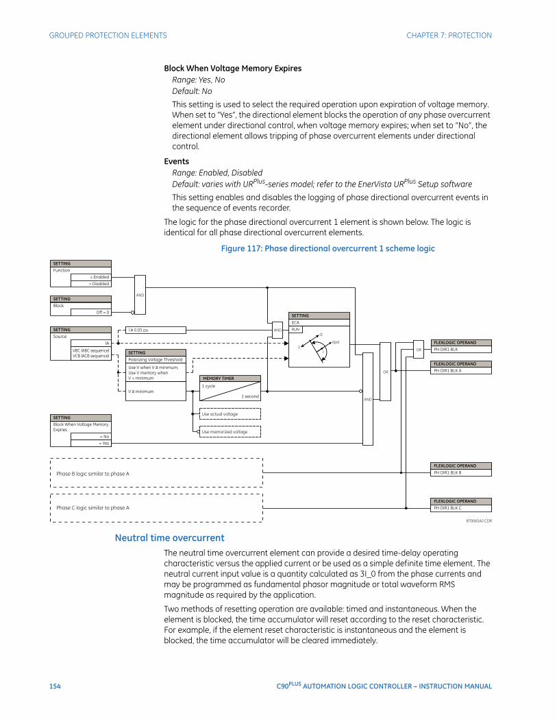
154 C90PLUS AUTOMATION LOGIC CONTROLLER – INSTRUCTION MANUAL
GROUPED PROTECTION ELEMENTS CHAPTER 7: PROTECTION
Block When Voltage Memory ExpiresRange: Yes, NoDefault: No
This setting is used to select the required operation upon expiration of voltage memory. When set to “Yes”, the directional element blocks the operation of any phase overcurrent element under directional control, when voltage memory expires; when set to “No”, the directional element allows tripping of phase overcurrent elements under directional control.
EventsRange: Enabled, DisabledDefault: varies with URPlus-series model; refer to the EnerVista URPlus Setup software
This setting enables and disables the logging of phase directional overcurrent events in the sequence of events recorder.
The logic for the phase directional overcurrent 1 element is shown below. The logic is identical for all phase directional overcurrent elements.
Figure 117: Phase directional overcurrent 1 scheme logic
Neutral time overcurrentThe neutral time overcurrent element can provide a desired time-delay operating characteristic versus the applied current or be used as a simple definite time element. The neutral current input value is a quantity calculated as 3I_0 from the phase currents and may be programmed as fundamental phasor magnitude or total waveform RMS magnitude as required by the application.
Two methods of resetting operation are available: timed and instantaneous. When the element is blocked, the time accumulator will reset according to the reset characteristic. For example, if the element reset characteristic is instantaneous and the element is blocked, the time accumulator will be cleared immediately.
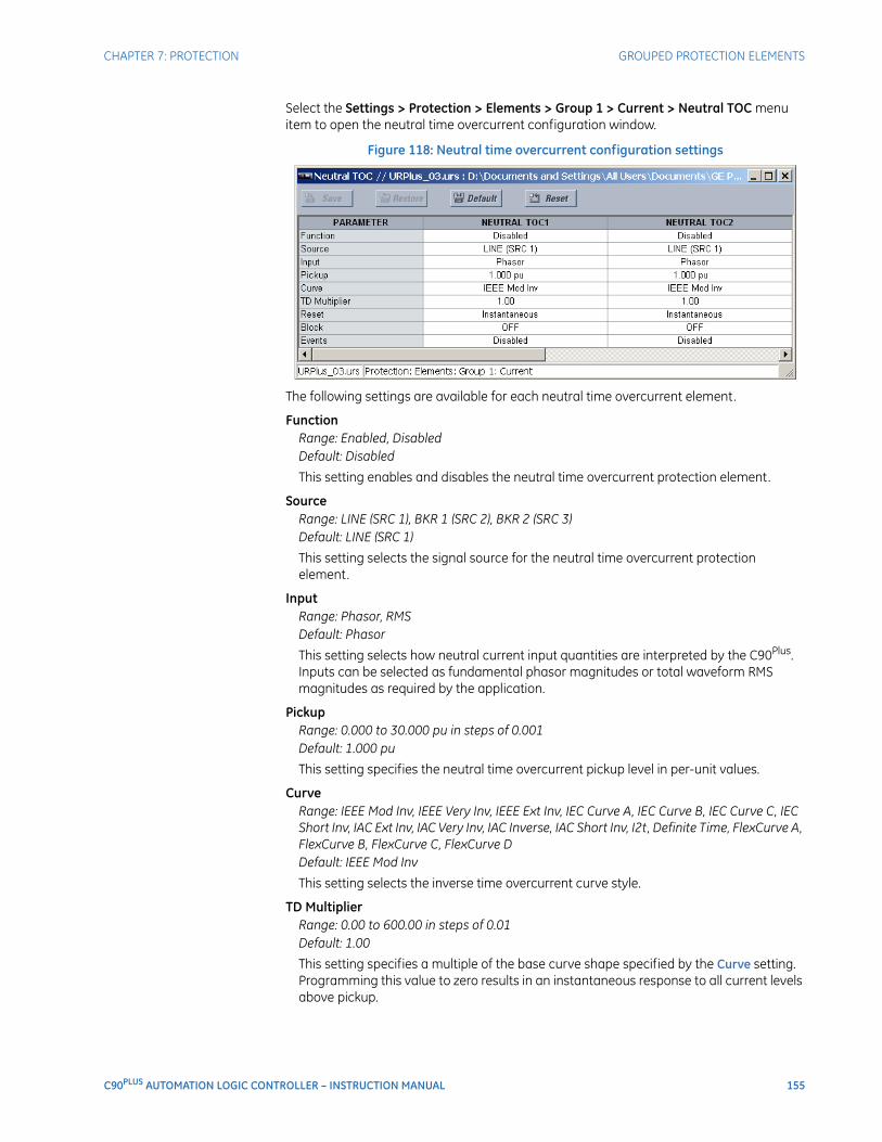
CHAPTER 7: PROTECTION GROUPED PROTECTION ELEMENTS
C90PLUS AUTOMATION LOGIC CONTROLLER – INSTRUCTION MANUAL 155
Select the Settings > Protection > Elements > Group 1 > Current > Neutral TOC menu item to open the neutral time overcurrent configuration window.
Figure 118: Neutral time overcurrent configuration settings
The following settings are available for each neutral time overcurrent element.
FunctionRange: Enabled, DisabledDefault: Disabled
This setting enables and disables the neutral time overcurrent protection element.
SourceRange: LINE (SRC 1), BKR 1 (SRC 2), BKR 2 (SRC 3)Default: LINE (SRC 1)
This setting selects the signal source for the neutral time overcurrent protection element.
InputRange: Phasor, RMSDefault: Phasor
This setting selects how neutral current input quantities are interpreted by the C90Plus. Inputs can be selected as fundamental phasor magnitudes or total waveform RMS magnitudes as required by the application.
PickupRange: 0.000 to 30.000 pu in steps of 0.001Default: 1.000 pu
This setting specifies the neutral time overcurrent pickup level in per-unit values.
CurveRange: IEEE Mod Inv, IEEE Very Inv, IEEE Ext Inv, IEC Curve A, IEC Curve B, IEC Curve C, IEC Short Inv, IAC Ext Inv, IAC Very Inv, IAC Inverse, IAC Short Inv, I2t, Definite Time, FlexCurve A, FlexCurve B, FlexCurve C, FlexCurve DDefault: IEEE Mod Inv
This setting selects the inverse time overcurrent curve style.
TD MultiplierRange: 0.00 to 600.00 in steps of 0.01Default: 1.00
This setting specifies a multiple of the base curve shape specified by the Curve setting. Programming this value to zero results in an instantaneous response to all current levels above pickup.
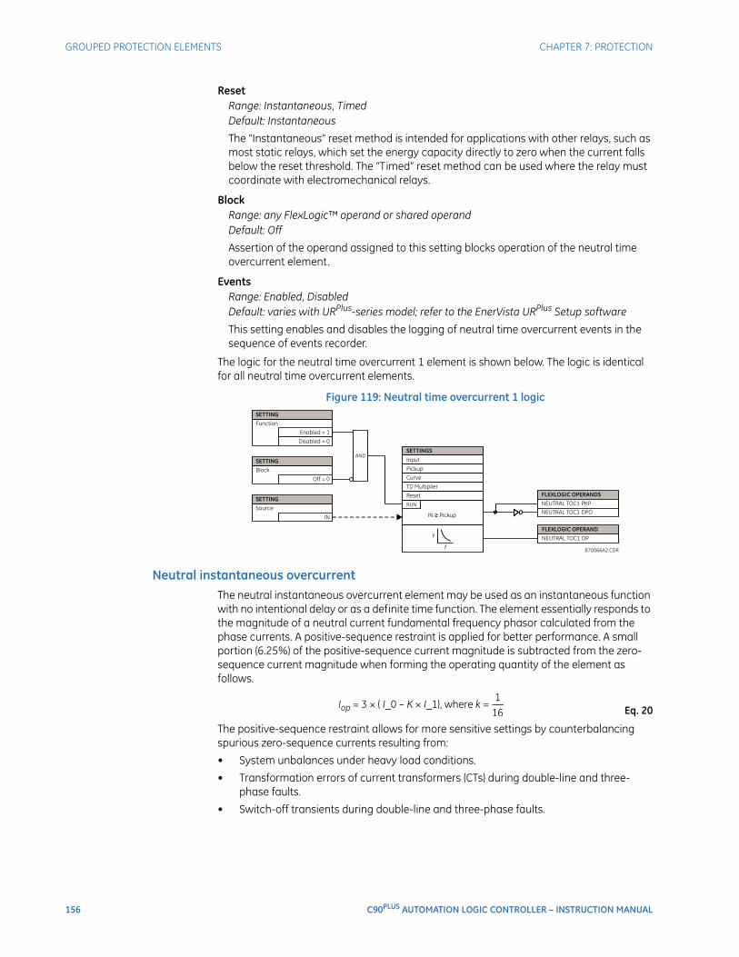
156 C90PLUS AUTOMATION LOGIC CONTROLLER – INSTRUCTION MANUAL
GROUPED PROTECTION ELEMENTS CHAPTER 7: PROTECTION
ResetRange: Instantaneous, TimedDefault: Instantaneous
The “Instantaneous” reset method is intended for applications with other relays, such as most static relays, which set the energy capacity directly to zero when the current falls below the reset threshold. The “Timed” reset method can be used where the relay must coordinate with electromechanical relays.
BlockRange: any FlexLogic™ operand or shared operandDefault: Off
Assertion of the operand assigned to this setting blocks operation of the neutral time overcurrent element.
EventsRange: Enabled, DisabledDefault: varies with URPlus-series model; refer to the EnerVista URPlus Setup software
This setting enables and disables the logging of neutral time overcurrent events in the sequence of events recorder.
The logic for the neutral time overcurrent 1 element is shown below. The logic is identical for all neutral time overcurrent elements.
Figure 119: Neutral time overcurrent 1 logic
Neutral instantaneous overcurrentThe neutral instantaneous overcurrent element may be used as an instantaneous function with no intentional delay or as a definite time function. The element essentially responds to the magnitude of a neutral current fundamental frequency phasor calculated from the phase currents. A positive-sequence restraint is applied for better performance. A small portion (6.25%) of the positive-sequence current magnitude is subtracted from the zero-sequence current magnitude when forming the operating quantity of the element as follows.
Eq. 20
The positive-sequence restraint allows for more sensitive settings by counterbalancing spurious zero-sequence currents resulting from:
• System unbalances under heavy load conditions.
• Transformation errors of current transformers (CTs) during double-line and three-phase faults.
• Switch-off transients during double-line and three-phase faults.
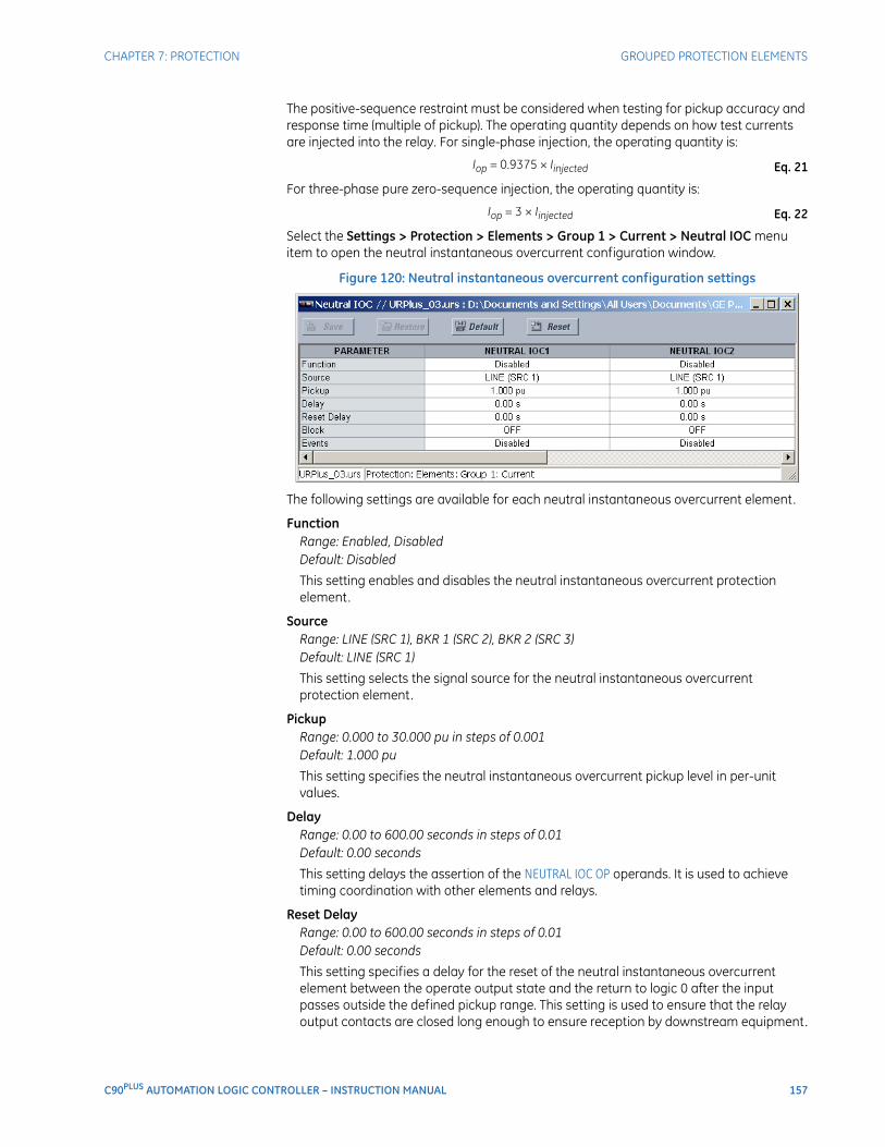
CHAPTER 7: PROTECTION GROUPED PROTECTION ELEMENTS
C90PLUS AUTOMATION LOGIC CONTROLLER – INSTRUCTION MANUAL 157
The positive-sequence restraint must be considered when testing for pickup accuracy and response time (multiple of pickup). The operating quantity depends on how test currents are injected into the relay. For single-phase injection, the operating quantity is:
Eq. 21
For three-phase pure zero-sequence injection, the operating quantity is:
Eq. 22
Select the Settings > Protection > Elements > Group 1 > Current > Neutral IOC menu item to open the neutral instantaneous overcurrent configuration window.
Figure 120: Neutral instantaneous overcurrent configuration settings
The following settings are available for each neutral instantaneous overcurrent element.
FunctionRange: Enabled, DisabledDefault: Disabled
This setting enables and disables the neutral instantaneous overcurrent protection element.
SourceRange: LINE (SRC 1), BKR 1 (SRC 2), BKR 2 (SRC 3)Default: LINE (SRC 1)
This setting selects the signal source for the neutral instantaneous overcurrent protection element.
PickupRange: 0.000 to 30.000 pu in steps of 0.001Default: 1.000 pu
This setting specifies the neutral instantaneous overcurrent pickup level in per-unit values.
DelayRange: 0.00 to 600.00 seconds in steps of 0.01Default: 0.00 seconds
This setting delays the assertion of the NEUTRAL IOC OP operands. It is used to achieve timing coordination with other elements and relays.
Reset DelayRange: 0.00 to 600.00 seconds in steps of 0.01Default: 0.00 seconds
This setting specifies a delay for the reset of the neutral instantaneous overcurrent element between the operate output state and the return to logic 0 after the input passes outside the defined pickup range. This setting is used to ensure that the relay output contacts are closed long enough to ensure reception by downstream equipment.
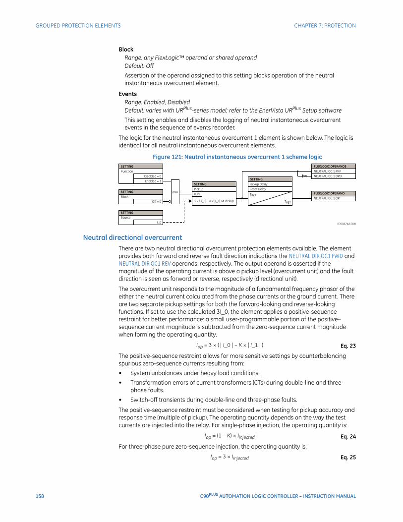
158 C90PLUS AUTOMATION LOGIC CONTROLLER – INSTRUCTION MANUAL
GROUPED PROTECTION ELEMENTS CHAPTER 7: PROTECTION
BlockRange: any FlexLogic™ operand or shared operandDefault: Off
Assertion of the operand assigned to this setting blocks operation of the neutral instantaneous overcurrent element.
EventsRange: Enabled, DisabledDefault: varies with URPlus-series model; refer to the EnerVista URPlus Setup software
This setting enables and disables the logging of neutral instantaneous overcurrent events in the sequence of events recorder.
The logic for the neutral instantaneous overcurrent 1 element is shown below. The logic is identical for all neutral instantaneous overcurrent elements.
Figure 121: Neutral instantaneous overcurrent 1 scheme logic
Neutral directional overcurrentThere are two neutral directional overcurrent protection elements available. The element provides both forward and reverse fault direction indications the NEUTRAL DIR OC1 FWD and NEUTRAL DIR OC1 REV operands, respectively. The output operand is asserted if the magnitude of the operating current is above a pickup level (overcurrent unit) and the fault direction is seen as forward or reverse, respectively (directional unit).
The overcurrent unit responds to the magnitude of a fundamental frequency phasor of the either the neutral current calculated from the phase currents or the ground current. There are two separate pickup settings for both the forward-looking and reverse-looking functions. If set to use the calculated 3I_0, the element applies a positive-sequence restraint for better performance: a small user-programmable portion of the positive–sequence current magnitude is subtracted from the zero-sequence current magnitude when forming the operating quantity.
Eq. 23
The positive-sequence restraint allows for more sensitive settings by counterbalancing spurious zero-sequence currents resulting from:
• System unbalances under heavy load conditions.
• Transformation errors of current transformers (CTs) during double-line and three-phase faults.
• Switch-off transients during double-line and three-phase faults.
The positive-sequence restraint must be considered when testing for pickup accuracy and response time (multiple of pickup). The operating quantity depends on the way the test currents are injected into the relay. For single-phase injection, the operating quantity is:
Eq. 24
For three-phase pure zero-sequence injection, the operating quantity is:
Eq. 25
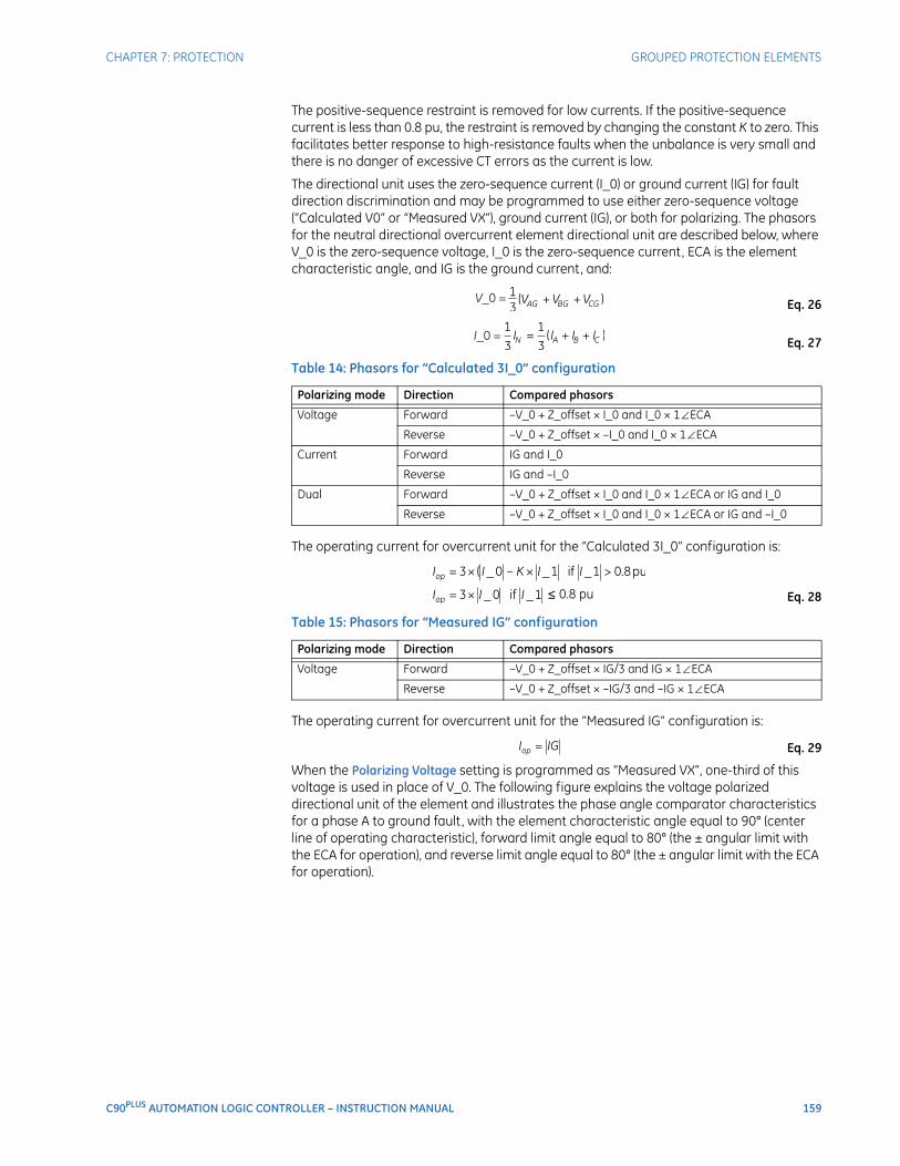
CHAPTER 7: PROTECTION GROUPED PROTECTION ELEMENTS
C90PLUS AUTOMATION LOGIC CONTROLLER – INSTRUCTION MANUAL 159
The positive-sequence restraint is removed for low currents. If the positive-sequence current is less than 0.8 pu, the restraint is removed by changing the constant K to zero. This facilitates better response to high-resistance faults when the unbalance is very small and there is no danger of excessive CT errors as the current is low.
The directional unit uses the zero-sequence current (I_0) or ground current (IG) for fault direction discrimination and may be programmed to use either zero-sequence voltage (“Calculated V0” or “Measured VX”), ground current (IG), or both for polarizing. The phasors for the neutral directional overcurrent element directional unit are described below, where V_0 is the zero-sequence voltage, I_0 is the zero-sequence current, ECA is the element characteristic angle, and IG is the ground current, and:
Eq. 26
Eq. 27
Table 14: Phasors for “Calculated 3I_0” configuration
The operating current for overcurrent unit for the “Calculated 3I_0” configuration is:
Eq. 28
Table 15: Phasors for “Measured IG” configuration
The operating current for overcurrent unit for the “Measured IG” configuration is:
Eq. 29
When the Polarizing Voltage setting is programmed as “Measured VX”, one-third of this voltage is used in place of V_0. The following figure explains the voltage polarized directional unit of the element and illustrates the phase angle comparator characteristics for a phase A to ground fault, with the element characteristic angle equal to 90° (center line of operating characteristic), forward limit angle equal to 80° (the ± angular limit with the ECA for operation), and reverse limit angle equal to 80° (the ± angular limit with the ECA for operation).
Polarizing mode Direction Compared phasors
Voltage Forward –V_0 + Z_offset × I_0 and I_0 × 1∠ECA
Reverse –V_0 + Z_offset × –I_0 and I_0 × 1∠ECA
Current Forward IG and I_0
Reverse IG and –I_0
Dual Forward –V_0 + Z_offset × I_0 and I_0 × 1∠ECA or IG and I_0
Reverse –V_0 + Z_offset × I_0 and I_0 × 1∠ECA or IG and –I_0
Polarizing mode Direction Compared phasors
Voltage Forward –V_0 + Z_offset × IG/3 and IG × 1∠ECA
Reverse –V_0 + Z_offset × –IG/3 and –IG × 1∠ECA
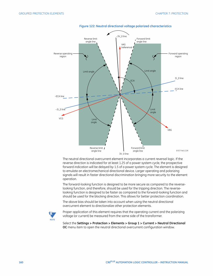
160 C90PLUS AUTOMATION LOGIC CONTROLLER – INSTRUCTION MANUAL
GROUPED PROTECTION ELEMENTS CHAPTER 7: PROTECTION
Figure 122: Neutral directional voltage polarized characteristics
The neutral directional overcurrent element incorporates a current reversal logic. If the reverse direction is indicated for at least 1.25 of a power system cycle, the prospective forward indication will be delayed by 1.5 of a power system cycle. The element is designed to emulate an electromechanical directional device. Larger operating and polarizing signals will result in faster directional discrimination bringing more security to the element operation.
The forward-looking function is designed to be more secure as compared to the reverse-looking function, and therefore, should be used for the tripping direction. The reverse-looking function is designed to be faster as compared to the forward-looking function and should be used for the blocking direction. This allows for better protection coordination.
The above bias should be taken into account when using the neutral directional overcurrent element to directionalize other protection elements.
NOTE
NOTE: Proper application of this element requires that the operating current and the polarizing voltage (or current) be measured from the same side of the transformer.
Select the Settings > Protection > Elements > Group 1 > Current > Neutral Directional OC menu item to open the neutral directional overcurrent configuration window.
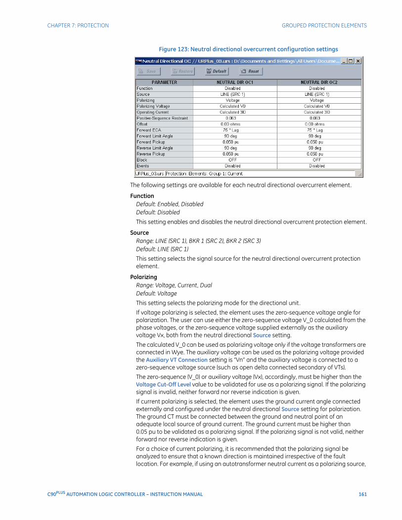
CHAPTER 7: PROTECTION GROUPED PROTECTION ELEMENTS
C90PLUS AUTOMATION LOGIC CONTROLLER – INSTRUCTION MANUAL 161
Figure 123: Neutral directional overcurrent configuration settings
The following settings are available for each neutral directional overcurrent element.
FunctionDefault: Enabled, DisabledDefault: Disabled
This setting enables and disables the neutral directional overcurrent protection element.
SourceRange: LINE (SRC 1), BKR 1 (SRC 2), BKR 2 (SRC 3)Default: LINE (SRC 1)
This setting selects the signal source for the neutral directional overcurrent protection element.
PolarizingRange: Voltage, Current, DualDefault: Voltage
This setting selects the polarizing mode for the directional unit.
If voltage polarizing is selected, the element uses the zero-sequence voltage angle for polarization. The user can use either the zero-sequence voltage V_0 calculated from the phase voltages, or the zero-sequence voltage supplied externally as the auxiliary voltage Vx, both from the neutral directional Source setting.
The calculated V_0 can be used as polarizing voltage only if the voltage transformers are connected in Wye. The auxiliary voltage can be used as the polarizing voltage provided the Auxiliary VT Connection setting is “Vn” and the auxiliary voltage is connected to a zero-sequence voltage source (such as open delta connected secondary of VTs).
The zero-sequence (V_0) or auxiliary voltage (Vx), accordingly, must be higher than the Voltage Cut-Off Level value to be validated for use as a polarizing signal. If the polarizing signal is invalid, neither forward nor reverse indication is given.
If current polarizing is selected, the element uses the ground current angle connected externally and configured under the neutral directional Source setting for polarization. The ground CT must be connected between the ground and neutral point of an adequate local source of ground current. The ground current must be higher than 0.05 pu to be validated as a polarizing signal. If the polarizing signal is not valid, neither forward nor reverse indication is given.
For a choice of current polarizing, it is recommended that the polarizing signal be analyzed to ensure that a known direction is maintained irrespective of the fault location. For example, if using an autotransformer neutral current as a polarizing source,

162 C90PLUS AUTOMATION LOGIC CONTROLLER – INSTRUCTION MANUAL
GROUPED PROTECTION ELEMENTS CHAPTER 7: PROTECTION
it should be ensured that a reversal of the ground current does not occur for a high-side fault. The low-side system impedance should be assumed minimal when checking for this condition. A similar situation arises for a wye/delta/wye transformer, where current in one transformer winding neutral may reverse when faults on both sides of the transformer are considered.
If dual polarizing is selected, the element performs both directional comparisons as described above. A given direction is confirmed if either voltage or current comparators indicate so. If a conflicting (simultaneous forward and reverse) indication occurs, the forward direction overrides the reverse direction.
Polarizing VoltageRange: Calculated V0, Measured VXDefault: Calculated V0
This setting selects the polarizing voltage used by the directional unit when the voltage or dual polarizing mode is set. The polarizing voltage can be programmed to be either the zero-sequence voltage calculated from the phase voltages (“Calculated V0”) or supplied externally as an auxiliary voltage (“Measured VX”).
Operating CurrentRange: Calculated 3I0, Measured IGDefault: Calculated 3I0
This setting indicates whether the 3I_0 current calculated from the phase currents, or the ground current shall be used by this protection. This setting acts as a switch between the neutral and ground modes of operation (ANSI devices 67N and 67G). If set to “Calculated 3I0”, the element uses the phase currents and applies the positive-sequence restraint; if set to “Measured IG”, the element uses ground current supplied to the ground CT of the CT bank configured as the neutral directional “Source”. If this setting is “Measured IG”, then the Polarizing setting must be “Voltage”, as it is not possible to use the ground current as an operating and polarizing signal simultaneously.
Positive-Sequence RestraintRange: 0.000 to 0.500 in steps of 0.001Default: 0.063
This setting controls the amount of the positive-sequence restraint. Set to 0.063 for backward compatibility with firmware revisions 3.40 and earlier. Set to zero to remove the restraint. Set higher if large system unbalances or poor CT performance are expected.
OffsetRange: 0.00 to 250.00 ohms in steps of 0.01Default: 0.00 ohms
This setting specifies the offset impedance used by this protection. The primary application for the offset impedance is to guarantee correct identification of fault direction on series compensated lines. In regular applications, the offset impedance ensures proper operation even if the zero-sequence voltage at the relaying point is very small. If this is the intent, the offset impedance shall not be larger than the zero-sequence impedance of the protected circuit. Practically, it shall be several times smaller. The offset impedance shall be entered in secondary ohms.
Forward ECARange: –90 to 90° in steps of 1Default: –70°
This setting defines the characteristic angle (ECA) for the forward direction in the voltage polarizing mode. The current polarizing mode uses a fixed ECA of 0°. The ECA in the reverse direction is the angle set for the forward direction shifted by 180°.

CHAPTER 7: PROTECTION GROUPED PROTECTION ELEMENTS
C90PLUS AUTOMATION LOGIC CONTROLLER – INSTRUCTION MANUAL 163
Forward Limit AngleRange: 40 to 90° in steps of 1Default: 90°
This setting defines a symmetrical (in both directions from the ECA) limit angle for the forward direction.
Forward PickupRange: 0.002 to 30.000 pu in steps of 0.001Default: 0.050 pu
This setting defines the pickup level for the overcurrent unit of the element in the forward direction. When selecting this setting it must be kept in mind that the design uses a positive-sequence restraint technique for the “Calculated 3I0” mode of operation.
Reverse Limit AngleRange: 40 to 90° in steps of 1Default: 90°
This setting defines a symmetrical (in both directions from the ECA) limit angle for the reverse direction.
Reverse PickupRange: 0.002 to 30.000 pu in steps of 0.001Default: 0.050 pu
This setting defines the pickup level for the overcurrent unit of the element in the reverse direction. When selecting this setting it must be kept in mind that the design uses a positive-sequence restraint technique for the “Calculated 3I0” mode of operation.
BlockRange: any FlexLogic™ operand or shared operandDefault: Off
Assertion of the operand assigned to this setting blocks operation of the neutral directional overcurrent element.
EventsRange: Enabled, DisabledDefault: varies with URPlus-series model; refer to the EnerVista URPlus Setup software
This setting enables and disables the logging of neutral directional overcurrent events in the sequence of events recorder.
The logic for the neutral directional overcurrent 1 element is shown below. The logic is identical for both neutral directional overcurrent elements.
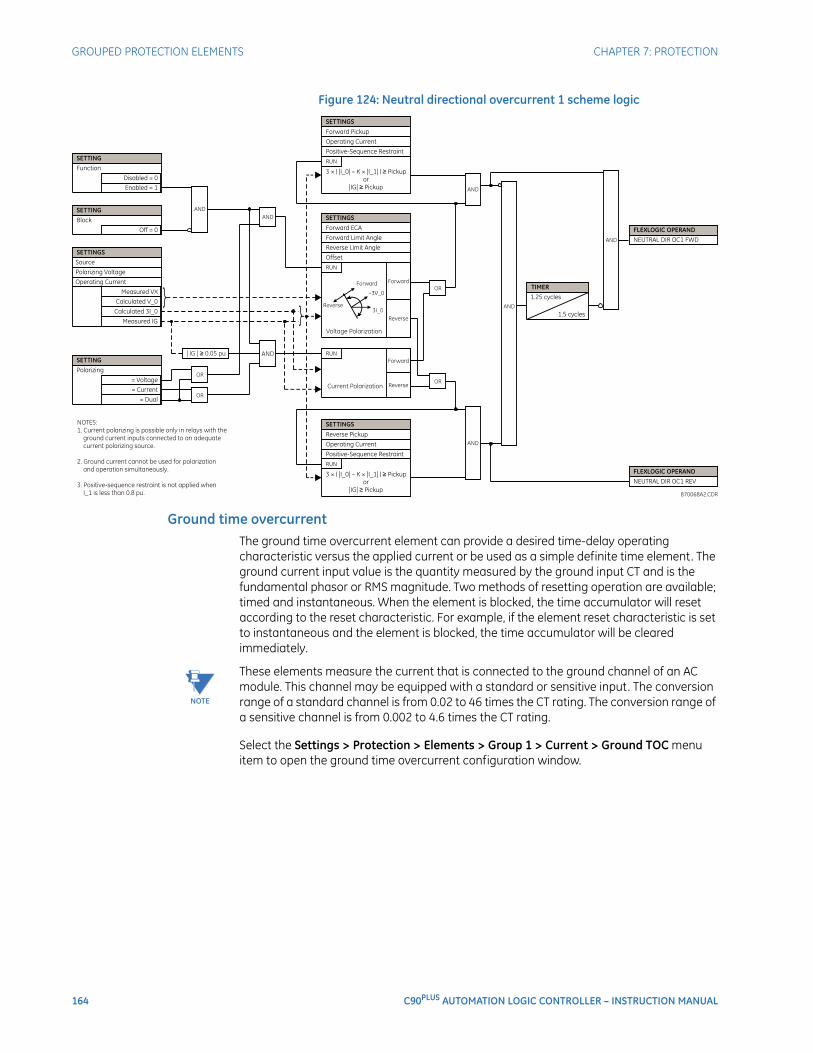
164 C90PLUS AUTOMATION LOGIC CONTROLLER – INSTRUCTION MANUAL
GROUPED PROTECTION ELEMENTS CHAPTER 7: PROTECTION
Figure 124: Neutral directional overcurrent 1 scheme logic
Ground time overcurrentThe ground time overcurrent element can provide a desired time-delay operating characteristic versus the applied current or be used as a simple definite time element. The ground current input value is the quantity measured by the ground input CT and is the fundamental phasor or RMS magnitude. Two methods of resetting operation are available; timed and instantaneous. When the element is blocked, the time accumulator will reset according to the reset characteristic. For example, if the element reset characteristic is set to instantaneous and the element is blocked, the time accumulator will be cleared immediately.
NOTE
NOTE: These elements measure the current that is connected to the ground channel of an AC module. This channel may be equipped with a standard or sensitive input. The conversion range of a standard channel is from 0.02 to 46 times the CT rating. The conversion range of a sensitive channel is from 0.002 to 4.6 times the CT rating.
Select the Settings > Protection > Elements > Group 1 > Current > Ground TOC menu item to open the ground time overcurrent configuration window.
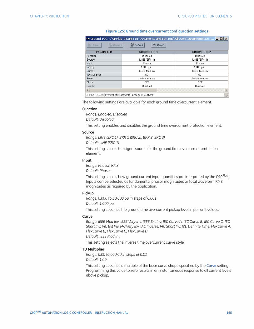
CHAPTER 7: PROTECTION GROUPED PROTECTION ELEMENTS
C90PLUS AUTOMATION LOGIC CONTROLLER – INSTRUCTION MANUAL 165
Figure 125: Ground time overcurrent configuration settings
The following settings are available for each ground time overcurrent element.
FunctionRange: Enabled, DisabledDefault: Disabled
This setting enables and disables the ground time overcurrent protection element.
SourceRange: LINE (SRC 1), BKR 1 (SRC 2), BKR 2 (SRC 3)Default: LINE (SRC 1)
This setting selects the signal source for the ground time overcurrent protection element.
InputRange: Phasor, RMSDefault: Phasor
This setting selects how ground current input quantities are interpreted by the C90Plus. Inputs can be selected as fundamental phasor magnitudes or total waveform RMS magnitudes as required by the application.
PickupRange: 0.000 to 30.000 pu in steps of 0.001Default: 1.000 pu
This setting specifies the ground time overcurrent pickup level in per-unit values.
CurveRange: IEEE Mod Inv, IEEE Very Inv, IEEE Ext Inv, IEC Curve A, IEC Curve B, IEC Curve C, IEC Short Inv, IAC Ext Inv, IAC Very Inv, IAC Inverse, IAC Short Inv, I2t, Definite Time, FlexCurve A, FlexCurve B, FlexCurve C, FlexCurve DDefault: IEEE Mod Inv
This setting selects the inverse time overcurrent curve style.
TD MultiplierRange: 0.00 to 600.00 in steps of 0.01Default: 1.00
This setting specifies a multiple of the base curve shape specified by the Curve setting. Programming this value to zero results in an instantaneous response to all current levels above pickup.
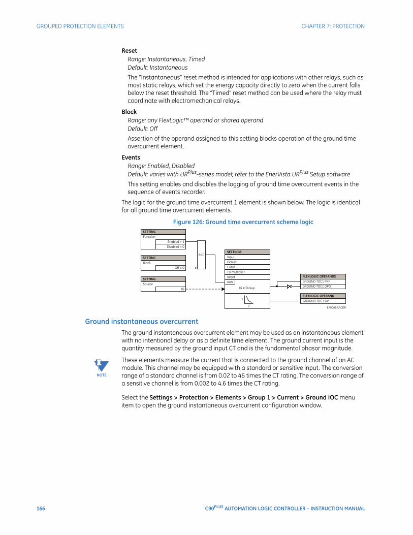
166 C90PLUS AUTOMATION LOGIC CONTROLLER – INSTRUCTION MANUAL
GROUPED PROTECTION ELEMENTS CHAPTER 7: PROTECTION
ResetRange: Instantaneous, TimedDefault: Instantaneous
The “Instantaneous” reset method is intended for applications with other relays, such as most static relays, which set the energy capacity directly to zero when the current falls below the reset threshold. The “Timed” reset method can be used where the relay must coordinate with electromechanical relays.
BlockRange: any FlexLogic™ operand or shared operandDefault: Off
Assertion of the operand assigned to this setting blocks operation of the ground time overcurrent element.
EventsRange: Enabled, DisabledDefault: varies with URPlus-series model; refer to the EnerVista URPlus Setup software
This setting enables and disables the logging of ground time overcurrent events in the sequence of events recorder.
The logic for the ground time overcurrent 1 element is shown below. The logic is identical for all ground time overcurrent elements.
Figure 126: Ground time overcurrent scheme logic
Ground instantaneous overcurrentThe ground instantaneous overcurrent element may be used as an instantaneous element with no intentional delay or as a definite time element. The ground current input is the quantity measured by the ground input CT and is the fundamental phasor magnitude.
NOTE
NOTE: These elements measure the current that is connected to the ground channel of an AC module. This channel may be equipped with a standard or sensitive input. The conversion range of a standard channel is from 0.02 to 46 times the CT rating. The conversion range of a sensitive channel is from 0.002 to 4.6 times the CT rating.
Select the Settings > Protection > Elements > Group 1 > Current > Ground IOC menu item to open the ground instantaneous overcurrent configuration window.
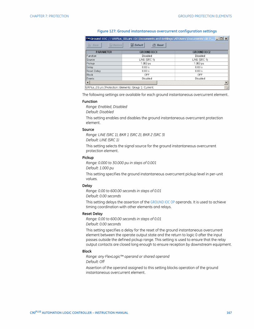
CHAPTER 7: PROTECTION GROUPED PROTECTION ELEMENTS
C90PLUS AUTOMATION LOGIC CONTROLLER – INSTRUCTION MANUAL 167
Figure 127: Ground instantaneous overcurrent configuration settings
The following settings are available for each ground instantaneous overcurrent element.
FunctionRange: Enabled, DisabledDefault: Disabled
This setting enables and disables the ground instantaneous overcurrent protection element.
SourceRange: LINE (SRC 1), BKR 1 (SRC 2), BKR 2 (SRC 3)Default: LINE (SRC 1)
This setting selects the signal source for the ground instantaneous overcurrent protection element.
PickupRange: 0.000 to 30.000 pu in steps of 0.001Default: 1.000 pu
This setting specifies the ground instantaneous overcurrent pickup level in per-unit values.
DelayRange: 0.00 to 600.00 seconds in steps of 0.01Default: 0.00 seconds
This setting delays the assertion of the GROUND IOC OP operands. It is used to achieve timing coordination with other elements and relays.
Reset DelayRange: 0.00 to 600.00 seconds in steps of 0.01Default: 0.00 seconds
This setting specifies a delay for the reset of the ground instantaneous overcurrent element between the operate output state and the return to logic 0 after the input passes outside the defined pickup range. This setting is used to ensure that the relay output contacts are closed long enough to ensure reception by downstream equipment.
BlockRange: any FlexLogic™ operand or shared operandDefault: Off
Assertion of the operand assigned to this setting blocks operation of the ground instantaneous overcurrent element.
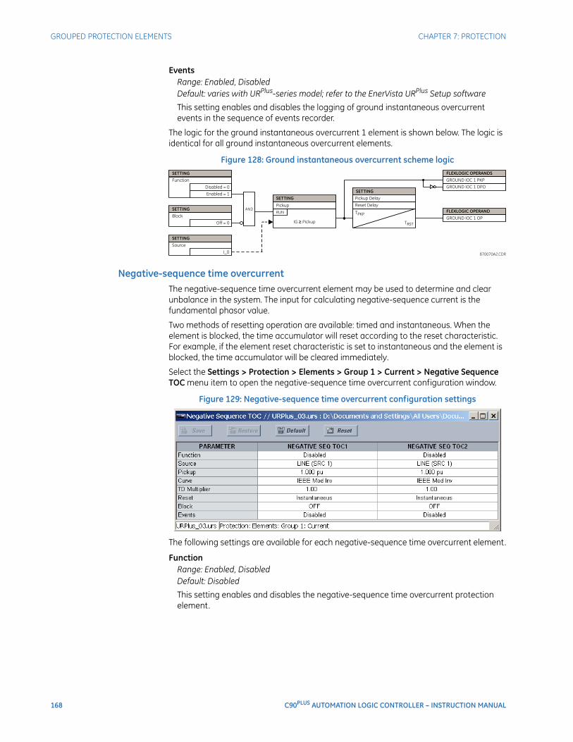
168 C90PLUS AUTOMATION LOGIC CONTROLLER – INSTRUCTION MANUAL
GROUPED PROTECTION ELEMENTS CHAPTER 7: PROTECTION
EventsRange: Enabled, DisabledDefault: varies with URPlus-series model; refer to the EnerVista URPlus Setup software
This setting enables and disables the logging of ground instantaneous overcurrent events in the sequence of events recorder.
The logic for the ground instantaneous overcurrent 1 element is shown below. The logic is identical for all ground instantaneous overcurrent elements.
Figure 128: Ground instantaneous overcurrent scheme logic
Negative-sequence time overcurrentThe negative-sequence time overcurrent element may be used to determine and clear unbalance in the system. The input for calculating negative-sequence current is the fundamental phasor value.
Two methods of resetting operation are available: timed and instantaneous. When the element is blocked, the time accumulator will reset according to the reset characteristic. For example, if the element reset characteristic is set to instantaneous and the element is blocked, the time accumulator will be cleared immediately.
Select the Settings > Protection > Elements > Group 1 > Current > Negative Sequence TOC menu item to open the negative-sequence time overcurrent configuration window.
Figure 129: Negative-sequence time overcurrent configuration settings
The following settings are available for each negative-sequence time overcurrent element.
FunctionRange: Enabled, DisabledDefault: Disabled
This setting enables and disables the negative-sequence time overcurrent protection element.

CHAPTER 7: PROTECTION GROUPED PROTECTION ELEMENTS
C90PLUS AUTOMATION LOGIC CONTROLLER – INSTRUCTION MANUAL 169
SourceRange: LINE (SRC 1), BKR 1 (SRC 2), BKR 2 (SRC 3)Default: LINE (SRC 1)
This setting selects the signal source for the negative-sequence time overcurrent protection element.
PickupRange: 0.000 to 30.000 pu in steps of 0.001Default: 1.000 pu
This setting specifies the neutral time overcurrent pickup level in per-unit values.
CurveRange: IEEE Mod Inv, IEEE Very Inv, IEEE Ext Inv, IEC Curve A, IEC Curve B, IEC Curve C, IEC Short Inv, IAC Ext Inv, IAC Very Inv, IAC Inverse, IAC Short Inv, I2t, Definite Time, FlexCurve A, FlexCurve B, FlexCurve C, FlexCurve DDefault: IEEE Mod Inv
This setting selects the inverse time overcurrent curve style.
TD MultiplierRange: 0.00 to 600.00 in steps of 0.01Default: 1.00
This setting specifies a multiple of the base curve shape specified by the Curve setting. Programming this value to zero results in an instantaneous response to all current levels above pickup.
ResetRange: Instantaneous, TimedDefault: Instantaneous
The “Instantaneous” reset method is intended for applications with other relays, such as most static relays, which set the energy capacity directly to zero when the current falls below the reset threshold. The “Timed” reset method can be used where the relay must coordinate with electromechanical relays.
BlockRange: any FlexLogic™ operand or shared operandDefault: Off
Assertion of the operand assigned to this setting blocks operation of the negative-sequence time overcurrent element.
EventsRange: Enabled, DisabledDefault: varies with URPlus-series model; refer to the EnerVista URPlus Setup software
This setting enables and disables the logging of negative-sequence time overcurrent events in the sequence of events recorder.
The logic for the negative-sequence time overcurrent 1 element is shown below. The logic is identical for all negative-sequence time overcurrent elements.
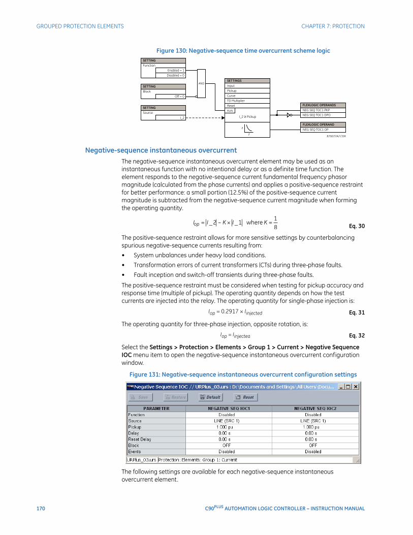
170 C90PLUS AUTOMATION LOGIC CONTROLLER – INSTRUCTION MANUAL
GROUPED PROTECTION ELEMENTS CHAPTER 7: PROTECTION
Figure 130: Negative-sequence time overcurrent scheme logic
Negative-sequence instantaneous overcurrentThe negative-sequence instantaneous overcurrent element may be used as an instantaneous function with no intentional delay or as a definite time function. The element responds to the negative-sequence current fundamental frequency phasor magnitude (calculated from the phase currents) and applies a positive-sequence restraint for better performance: a small portion (12.5%) of the positive-sequence current magnitude is subtracted from the negative-sequence current magnitude when forming the operating quantity.
Eq. 30
The positive-sequence restraint allows for more sensitive settings by counterbalancing spurious negative-sequence currents resulting from:
• System unbalances under heavy load conditions.
• Transformation errors of current transformers (CTs) during three-phase faults.
• Fault inception and switch-off transients during three-phase faults.
The positive-sequence restraint must be considered when testing for pickup accuracy and response time (multiple of pickup). The operating quantity depends on how the test currents are injected into the relay. The operating quantity for single-phase injection is:
Eq. 31
The operating quantity for three-phase injection, opposite rotation, is:
Eq. 32
Select the Settings > Protection > Elements > Group 1 > Current > Negative Sequence IOC menu item to open the negative-sequence instantaneous overcurrent configuration window.
Figure 131: Negative-sequence instantaneous overcurrent configuration settings
The following settings are available for each negative-sequence instantaneous overcurrent element.

CHAPTER 7: PROTECTION GROUPED PROTECTION ELEMENTS
C90PLUS AUTOMATION LOGIC CONTROLLER – INSTRUCTION MANUAL 171
FunctionRange: Enabled, DisabledDefault: Disabled
This setting enables and disables the negative-sequence instantaneous overcurrent protection element.
SourceRange: LINE (SRC 1), BKR 1 (SRC 2), BKR 2 (SRC 3)Default: LINE (SRC 1)
This setting selects the signal source for the negative-sequence instantaneous overcurrent protection element.
PickupRange: 0.000 to 30.000 pu in steps of 0.001Default: 1.000 pu
This setting specifies the negative-sequence instantaneous overcurrent pickup level in per-unit values.
DelayRange: 0.00 to 600.00 seconds in steps of 0.01Default: 0.00 seconds
This setting delays the assertion of the NEG SEQ IOC OP operands. It is used to achieve timing coordination with other elements and relays.
Reset DelayRange: 0.00 to 600.00 seconds in steps of 0.01Default: 0.00 seconds
This setting specifies a delay for the reset of the phase instantaneous overcurrent element between the operate output state and the return to logic 0 after the input passes outside the defined pickup range. This setting is used to ensure that the relay output contacts are closed long enough to ensure reception by downstream equipment.
BlockRange: any FlexLogic™ operand or shared operandDefault: Off
Assertion of the operand assigned to this setting blocks operation of the negative-sequence instantaneous overcurrent element.
EventsRange: Enabled, DisabledDefault: varies with URPlus-series model; refer to the EnerVista URPlus Setup software
This setting enables and disables the logging of negative-sequence instantaneous overcurrent events in the sequence of events recorder.
The logic for the negative-sequence instantaneous overcurrent 1 element is shown below. The logic is identical for all negative-sequence instantaneous overcurrent elements.
Figure 132: Negative-sequence instantaneous overcurrent scheme logic
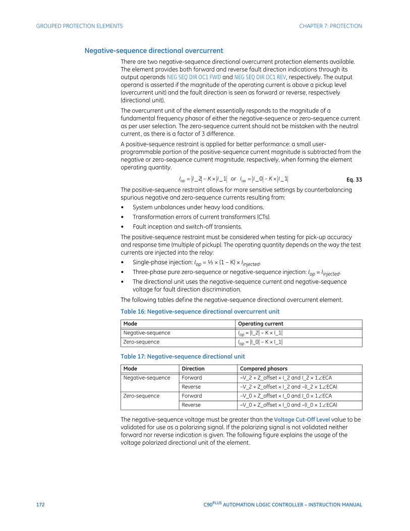
172 C90PLUS AUTOMATION LOGIC CONTROLLER – INSTRUCTION MANUAL
GROUPED PROTECTION ELEMENTS CHAPTER 7: PROTECTION
Negative-sequence directional overcurrentThere are two negative-sequence directional overcurrent protection elements available. The element provides both forward and reverse fault direction indications through its output operands NEG SEQ DIR OC1 FWD and NEG SEQ DIR OC1 REV, respectively. The output operand is asserted if the magnitude of the operating current is above a pickup level (overcurrent unit) and the fault direction is seen as forward or reverse, respectively (directional unit).
The overcurrent unit of the element essentially responds to the magnitude of a fundamental frequency phasor of either the negative-sequence or zero-sequence current as per user selection. The zero-sequence current should not be mistaken with the neutral current, as there is a factor of 3 difference.
A positive-sequence restraint is applied for better performance: a small user-programmable portion of the positive-sequence current magnitude is subtracted from the negative or zero-sequence current magnitude, respectively, when forming the element operating quantity.
Eq. 33
The positive-sequence restraint allows for more sensitive settings by counterbalancing spurious negative and zero-sequence currents resulting from:
• System unbalances under heavy load conditions.
• Transformation errors of current transformers (CTs).
• Fault inception and switch-off transients.
The positive-sequence restraint must be considered when testing for pick-up accuracy and response time (multiple of pickup). The operating quantity depends on the way the test currents are injected into the relay:
• Single-phase injection: Iop = ⅓ × (1 – K) × Iinjected.
• Three-phase pure zero-sequence or negative-sequence injection: Iop = Iinjected.
• The directional unit uses the negative-sequence current and negative-sequence voltage for fault direction discrimination.
The following tables define the negative-sequence directional overcurrent element.
Table 16: Negative-sequence directional overcurrent unit
Table 17: Negative-sequence directional unit
The negative-sequence voltage must be greater than the Voltage Cut-Off Level value to be validated for use as a polarizing signal. If the polarizing signal is not validated neither forward nor reverse indication is given. The following figure explains the usage of the voltage polarized directional unit of the element.
Mode Operating current
Negative-sequence Iop = |I_2| – K × I_1|
Zero-sequence Iop = |I_0| – K × I_1|
Mode Direction Compared phasors
Negative-sequence Forward –V_2 + Z_offset × I_2 and I_2 × 1∠ECA
Reverse –V_2 + Z_offset × I_2 and –(I_2 × 1∠ECA)
Zero-sequence Forward –V_0 + Z_offset × I_0 and I_0 × 1∠ECA
Reverse –V_0 + Z_offset × I_0 and –(I_0 × 1∠ECA)
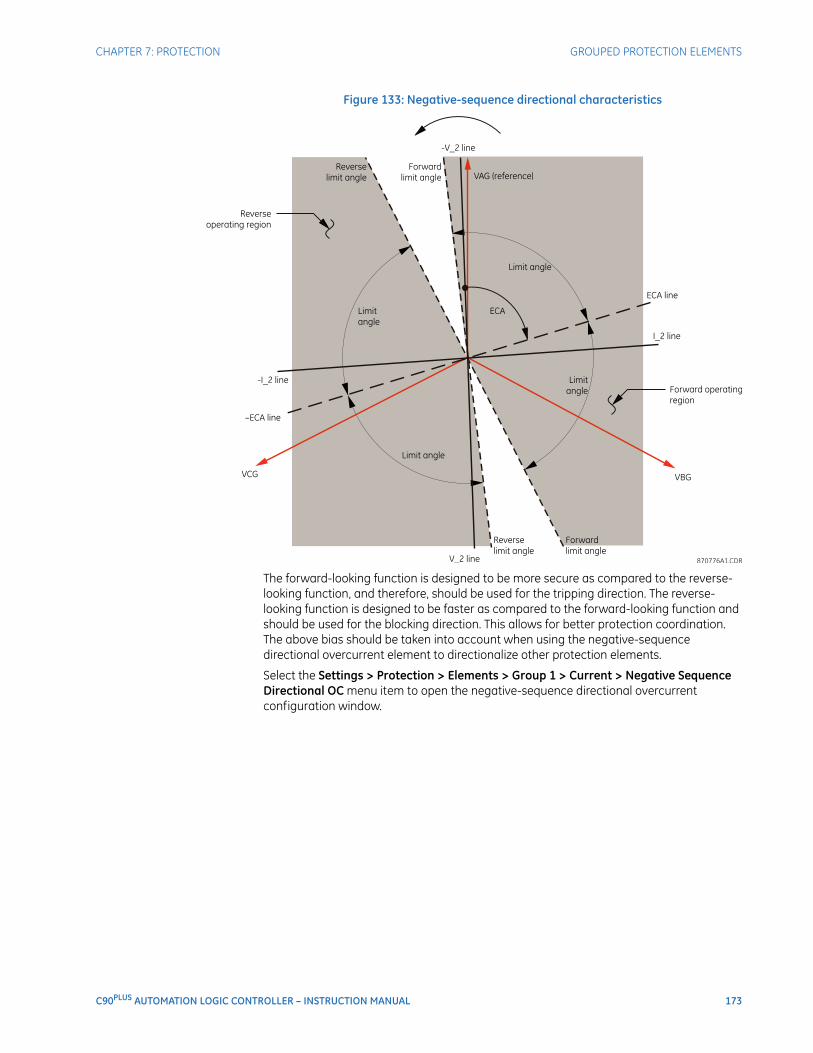
CHAPTER 7: PROTECTION GROUPED PROTECTION ELEMENTS
C90PLUS AUTOMATION LOGIC CONTROLLER – INSTRUCTION MANUAL 173
Figure 133: Negative-sequence directional characteristics
The forward-looking function is designed to be more secure as compared to the reverse-looking function, and therefore, should be used for the tripping direction. The reverse-looking function is designed to be faster as compared to the forward-looking function and should be used for the blocking direction. This allows for better protection coordination. The above bias should be taken into account when using the negative-sequence directional overcurrent element to directionalize other protection elements.
Select the Settings > Protection > Elements > Group 1 > Current > Negative Sequence Directional OC menu item to open the negative-sequence directional overcurrent configuration window.
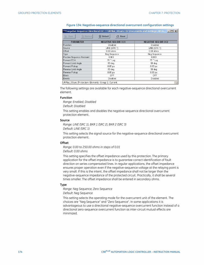
174 C90PLUS AUTOMATION LOGIC CONTROLLER – INSTRUCTION MANUAL
GROUPED PROTECTION ELEMENTS CHAPTER 7: PROTECTION
Figure 134: Negative-sequence directional overcurrent configuration settings
The following settings are available for each negative-sequence directional overcurrent element.
FunctionRange: Enabled, DisabledDefault: Disabled
This setting enables and disables the negative-sequence directional overcurrent protection element.
SourceRange: LINE (SRC 1), BKR 1 (SRC 2), BKR 2 (SRC 3)Default: LINE (SRC 1)
This setting selects the signal source for the negative-sequence directional overcurrent protection element.
OffsetRange: 0.00 to 250.00 ohms in steps of 0.01Default: 0.00 ohms
This setting specifies the offset impedance used by this protection. The primary application for the offset impedance is to guarantee correct identification of fault direction on series compensated lines. In regular applications, the offset impedance ensures proper operation even if the negative-sequence voltage at the relaying point is very small. If this is the intent, the offset impedance shall not be larger than the negative-sequence impedance of the protected circuit. Practically, it shall be several times smaller. The offset impedance shall be entered in secondary ohms.
TypeRange: Neg Sequence, Zero SequenceDefault: Neg Sequence
This setting selects the operating mode for the overcurrent unit of the element. The choices are “Neg Sequence” and “Zero Sequence”. In some applications it is advantageous to use a directional negative-sequence overcurrent function instead of a directional zero-sequence overcurrent function as inter-circuit mutual effects are minimized.

CHAPTER 7: PROTECTION GROUPED PROTECTION ELEMENTS
C90PLUS AUTOMATION LOGIC CONTROLLER – INSTRUCTION MANUAL 175
Pos Seq RestraintRange: 0.000 to 0.500 in steps of 0.001Default: 0.063
This setting controls the amount of the positive-sequence restraint. Set to 0.063 (in zero-sequence mode) or 0.125 (in negative-sequence mode) for backwards compatibility with UR-series relays using firmware revision 3.40 and older. Set to zero to remove the restraint. Set higher if large system unbalances or poor CT performance are expected.
Forward ECARange: 0 to 90° Lag in steps of 1Default: 75° Lag
This setting specifies the element characteristic angle (ECA) for the forward direction. The element characteristic angle in the reverse direction is the angle set for the forward direction shifted by 180°.
Forward Limit AngleRange: 40 to 90° in steps of 1Default: 90°
This setting specifies a symmetrical limit angle (in both directions from the element characteristic angle) for the forward direction.
Forward PickupRange: 0.05 to 30.00 pu in steps of 0.01Default: 0.05 pu
This setting specifies the pickup level for the overcurrent unit in the forward direction. This pickup threshold applies to zero or negative-sequence current based on the Type setting. When specifying this setting, it must be kept in mind that the design uses a positive-sequence restraint technique.
Reverse Limit AngleRange: 40 to 90° in steps of 1Default: 90°
This setting defines a symmetrical (in both directions from the element characteristic angle) limit angle for the reverse direction.
Reverse PickupRange: 0.05 to 30.00 pu in steps of 0.01Default: 0.05 pu
This setting specifies the pickup level for the overcurrent unit in the reverse direction. This pickup threshold applies to zero or negative-sequence current based on the Type setting. When specifying this setting, it must be kept in mind that the design uses a positive-sequence restraint technique.
BlockRange: any FlexLogic™ operand or shared operandDefault: Off
Assertion of the operand assigned to this setting blocks operation of the negative-sequence directional overcurrent element.
EventsRange: Enabled, DisabledDefault: varies with URPlus-series model; refer to the EnerVista URPlus Setup software
This setting enables and disables the logging of negative-sequence directional overcurrent events in the sequence of events recorder.
The logic for the negative-sequence directional overcurrent 1 element is shown below. The logic is identical for all negative-sequence directional overcurrent elements.
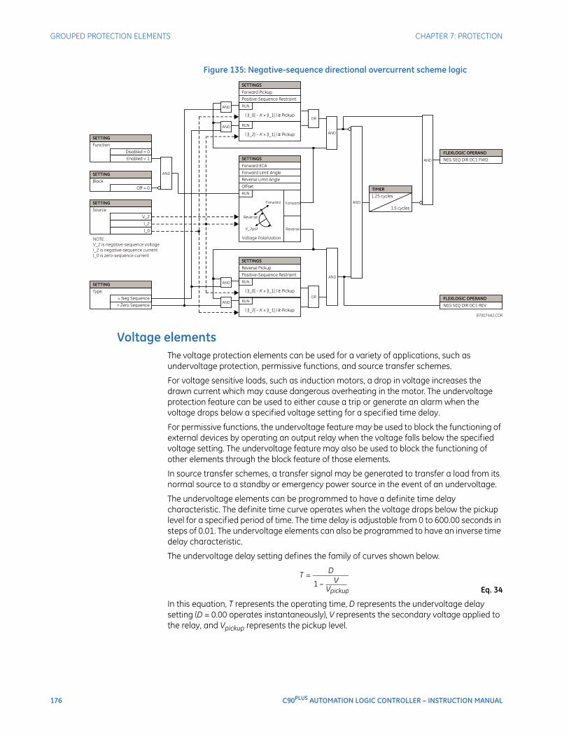
176 C90PLUS AUTOMATION LOGIC CONTROLLER – INSTRUCTION MANUAL
GROUPED PROTECTION ELEMENTS CHAPTER 7: PROTECTION
Figure 135: Negative-sequence directional overcurrent scheme logic
Voltage elementsThe voltage protection elements can be used for a variety of applications, such as undervoltage protection, permissive functions, and source transfer schemes.
For voltage sensitive loads, such as induction motors, a drop in voltage increases the drawn current which may cause dangerous overheating in the motor. The undervoltage protection feature can be used to either cause a trip or generate an alarm when the voltage drops below a specified voltage setting for a specified time delay.
For permissive functions, the undervoltage feature may be used to block the functioning of external devices by operating an output relay when the voltage falls below the specified voltage setting. The undervoltage feature may also be used to block the functioning of other elements through the block feature of those elements.
In source transfer schemes, a transfer signal may be generated to transfer a load from its normal source to a standby or emergency power source in the event of an undervoltage.
The undervoltage elements can be programmed to have a definite time delay characteristic. The definite time curve operates when the voltage drops below the pickup level for a specified period of time. The time delay is adjustable from 0 to 600.00 seconds in steps of 0.01. The undervoltage elements can also be programmed to have an inverse time delay characteristic.
The undervoltage delay setting defines the family of curves shown below.
Eq. 34
In this equation, T represents the operating time, D represents the undervoltage delay setting (D = 0.00 operates instantaneously), V represents the secondary voltage applied to the relay, and Vpickup represents the pickup level.
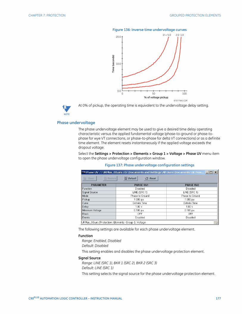
CHAPTER 7: PROTECTION GROUPED PROTECTION ELEMENTS
C90PLUS AUTOMATION LOGIC CONTROLLER – INSTRUCTION MANUAL 177
Figure 136: Inverse time undervoltage curves
NOTE
NOTE: At 0% of pickup, the operating time is equivalent to the undervoltage delay setting.
Phase undervoltageThe phase undervoltage element may be used to give a desired time delay operating characteristic versus the applied fundamental voltage (phase-to-ground or phase-to-phase for wye VT connections, or phase-to-phase for delta VT connections) or as a definite time element. The element resets instantaneously if the applied voltage exceeds the dropout voltage.
Select the Settings > Protection > Elements > Group 1 > Voltage > Phase UV menu item to open the phase undervoltage configuration window.
Figure 137: Phase undervoltage configuration settings
The following settings are available for each phase undervoltage element.
FunctionRange: Enabled, DisabledDefault: Disabled
This setting enables and disables the phase undervoltage protection element.
Signal SourceRange: LINE (SRC 1), BKR 1 (SRC 2), BKR 2 (SRC 3)Default: LINE (SRC 1)
This setting selects the signal source for the phase undervoltage protection element.

178 C90PLUS AUTOMATION LOGIC CONTROLLER – INSTRUCTION MANUAL
GROUPED PROTECTION ELEMENTS CHAPTER 7: PROTECTION
ModeRange: Phase to Ground, Phase to PhaseDefault: Phase to Ground
This setting selects the operating mode. Select phase-to-ground or phase-to-phase for wye VT connections, or phase-to-phase for delta VT connections.
PickupRange: 0.000 to 1.100 pu in steps of 0.001Default: 1.000 pu
This setting specifies the phase undervoltage pickup level in per-unit values.
CurveRange: Definite Time, Inverse TimeDefault: Definite Time
This setting selects the desired time-delay operating characteristic versus the applied fundamental voltage or the definite time element.
DelayRange: 0.00 to 600.00 seconds in steps of 0.01Default: 1.00 seconds
This setting specifies the minimum operating time of the phase undervoltage element.
Minimum VoltageRange: 0.000 to 3.000 pu in steps of 0.001Default: 0.100 pu
This setting specifies the operating voltage in per-unit values below which the element is blocked. A value of “0” will allow a dead source to be considered a fault condition.
BlockRange: any FlexLogic™ operand or shared operandDefault: Off
Assertion of the operand assigned to this setting blocks the phase undervoltage element.
EventsRange: Enabled, DisabledDefault: Disabled
This setting enables and disables the logging of phase undervoltage events in the sequence of events recorder.
The logic for the phase undervoltage element is shown below. The logic is identical for all phase undervoltage elements.
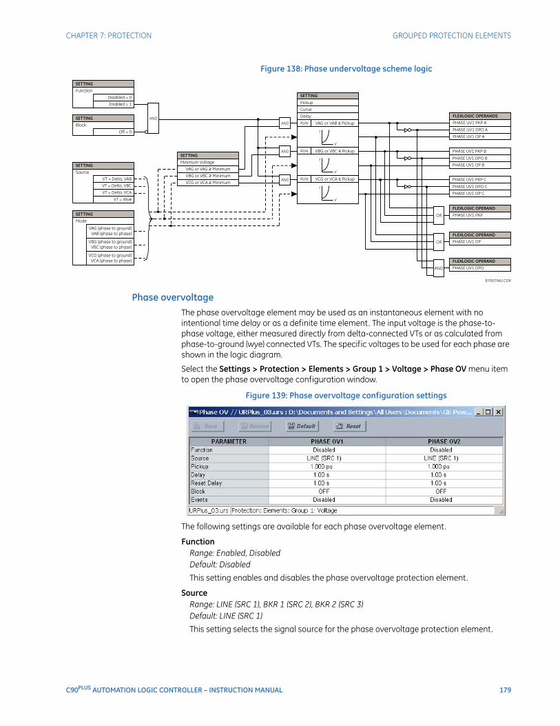
CHAPTER 7: PROTECTION GROUPED PROTECTION ELEMENTS
C90PLUS AUTOMATION LOGIC CONTROLLER – INSTRUCTION MANUAL 179
Figure 138: Phase undervoltage scheme logic
Phase overvoltageThe phase overvoltage element may be used as an instantaneous element with no intentional time delay or as a definite time element. The input voltage is the phase-to-phase voltage, either measured directly from delta-connected VTs or as calculated from phase-to-ground (wye) connected VTs. The specific voltages to be used for each phase are shown in the logic diagram.
Select the Settings > Protection > Elements > Group 1 > Voltage > Phase OV menu item to open the phase overvoltage configuration window.
Figure 139: Phase overvoltage configuration settings
The following settings are available for each phase overvoltage element.
FunctionRange: Enabled, DisabledDefault: Disabled
This setting enables and disables the phase overvoltage protection element.
SourceRange: LINE (SRC 1), BKR 1 (SRC 2), BKR 2 (SRC 3)Default: LINE (SRC 1)
This setting selects the signal source for the phase overvoltage protection element.
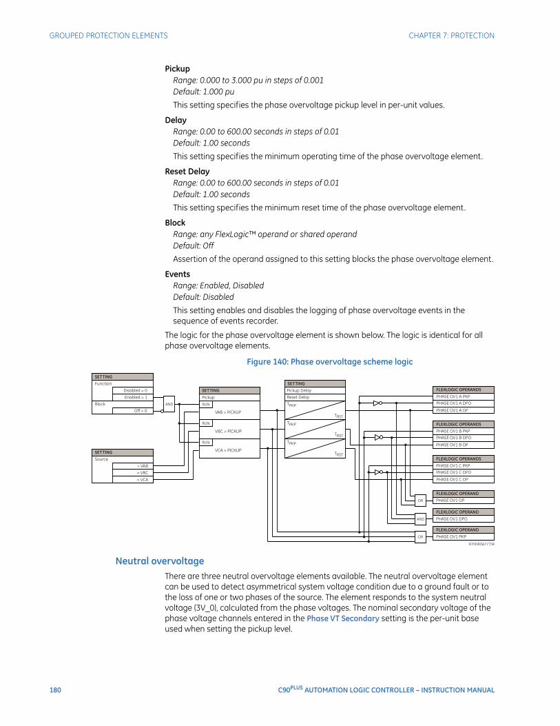
180 C90PLUS AUTOMATION LOGIC CONTROLLER – INSTRUCTION MANUAL
GROUPED PROTECTION ELEMENTS CHAPTER 7: PROTECTION
PickupRange: 0.000 to 3.000 pu in steps of 0.001Default: 1.000 pu
This setting specifies the phase overvoltage pickup level in per-unit values.
DelayRange: 0.00 to 600.00 seconds in steps of 0.01Default: 1.00 seconds
This setting specifies the minimum operating time of the phase overvoltage element.
Reset DelayRange: 0.00 to 600.00 seconds in steps of 0.01Default: 1.00 seconds
This setting specifies the minimum reset time of the phase overvoltage element.
BlockRange: any FlexLogic™ operand or shared operandDefault: Off
Assertion of the operand assigned to this setting blocks the phase overvoltage element.
EventsRange: Enabled, DisabledDefault: Disabled
This setting enables and disables the logging of phase overvoltage events in the sequence of events recorder.
The logic for the phase overvoltage element is shown below. The logic is identical for all phase overvoltage elements.
Figure 140: Phase overvoltage scheme logic
Neutral overvoltageThere are three neutral overvoltage elements available. The neutral overvoltage element can be used to detect asymmetrical system voltage condition due to a ground fault or to the loss of one or two phases of the source. The element responds to the system neutral voltage (3V_0), calculated from the phase voltages. The nominal secondary voltage of the phase voltage channels entered in the Phase VT Secondary setting is the per-unit base used when setting the pickup level.
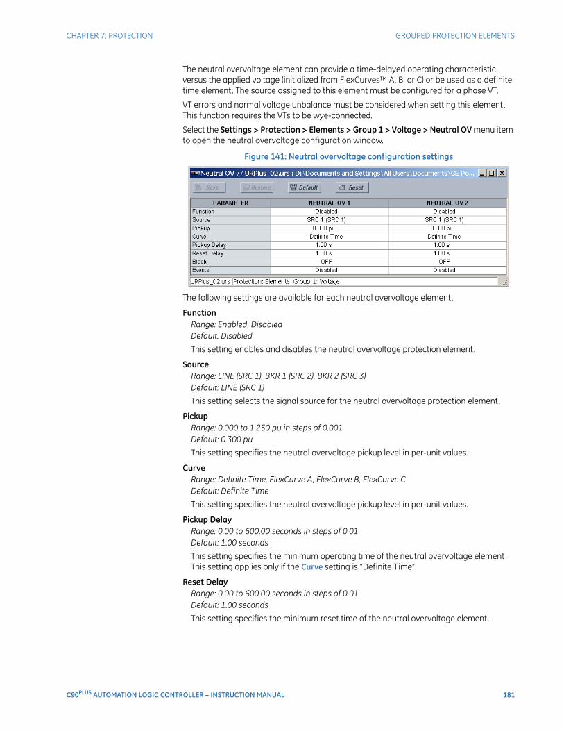
CHAPTER 7: PROTECTION GROUPED PROTECTION ELEMENTS
C90PLUS AUTOMATION LOGIC CONTROLLER – INSTRUCTION MANUAL 181
The neutral overvoltage element can provide a time-delayed operating characteristic versus the applied voltage (initialized from FlexCurves™ A, B, or C) or be used as a definite time element. The source assigned to this element must be configured for a phase VT.
VT errors and normal voltage unbalance must be considered when setting this element. This function requires the VTs to be wye-connected.
Select the Settings > Protection > Elements > Group 1 > Voltage > Neutral OV menu item to open the neutral overvoltage configuration window.
Figure 141: Neutral overvoltage configuration settings
The following settings are available for each neutral overvoltage element.
FunctionRange: Enabled, DisabledDefault: Disabled
This setting enables and disables the neutral overvoltage protection element.
SourceRange: LINE (SRC 1), BKR 1 (SRC 2), BKR 2 (SRC 3)Default: LINE (SRC 1)
This setting selects the signal source for the neutral overvoltage protection element.
PickupRange: 0.000 to 1.250 pu in steps of 0.001Default: 0.300 pu
This setting specifies the neutral overvoltage pickup level in per-unit values.
CurveRange: Definite Time, FlexCurve A, FlexCurve B, FlexCurve CDefault: Definite Time
This setting specifies the neutral overvoltage pickup level in per-unit values.
Pickup DelayRange: 0.00 to 600.00 seconds in steps of 0.01Default: 1.00 seconds
This setting specifies the minimum operating time of the neutral overvoltage element. This setting applies only if the Curve setting is “Definite Time”.
Reset DelayRange: 0.00 to 600.00 seconds in steps of 0.01Default: 1.00 seconds
This setting specifies the minimum reset time of the neutral overvoltage element.
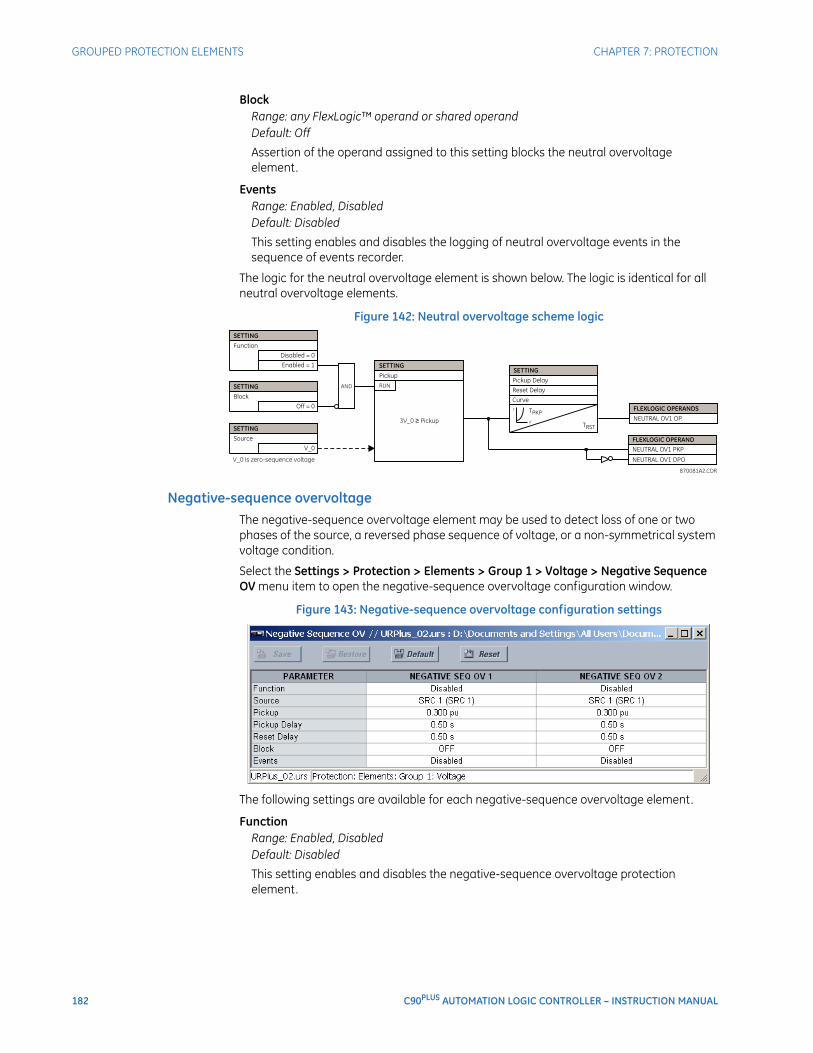
182 C90PLUS AUTOMATION LOGIC CONTROLLER – INSTRUCTION MANUAL
GROUPED PROTECTION ELEMENTS CHAPTER 7: PROTECTION
BlockRange: any FlexLogic™ operand or shared operandDefault: Off
Assertion of the operand assigned to this setting blocks the neutral overvoltage element.
EventsRange: Enabled, DisabledDefault: Disabled
This setting enables and disables the logging of neutral overvoltage events in the sequence of events recorder.
The logic for the neutral overvoltage element is shown below. The logic is identical for all neutral overvoltage elements.
Figure 142: Neutral overvoltage scheme logic
Negative-sequence overvoltageThe negative-sequence overvoltage element may be used to detect loss of one or two phases of the source, a reversed phase sequence of voltage, or a non-symmetrical system voltage condition.
Select the Settings > Protection > Elements > Group 1 > Voltage > Negative Sequence OV menu item to open the negative-sequence overvoltage configuration window.
Figure 143: Negative-sequence overvoltage configuration settings
The following settings are available for each negative-sequence overvoltage element.
FunctionRange: Enabled, DisabledDefault: Disabled
This setting enables and disables the negative-sequence overvoltage protection element.
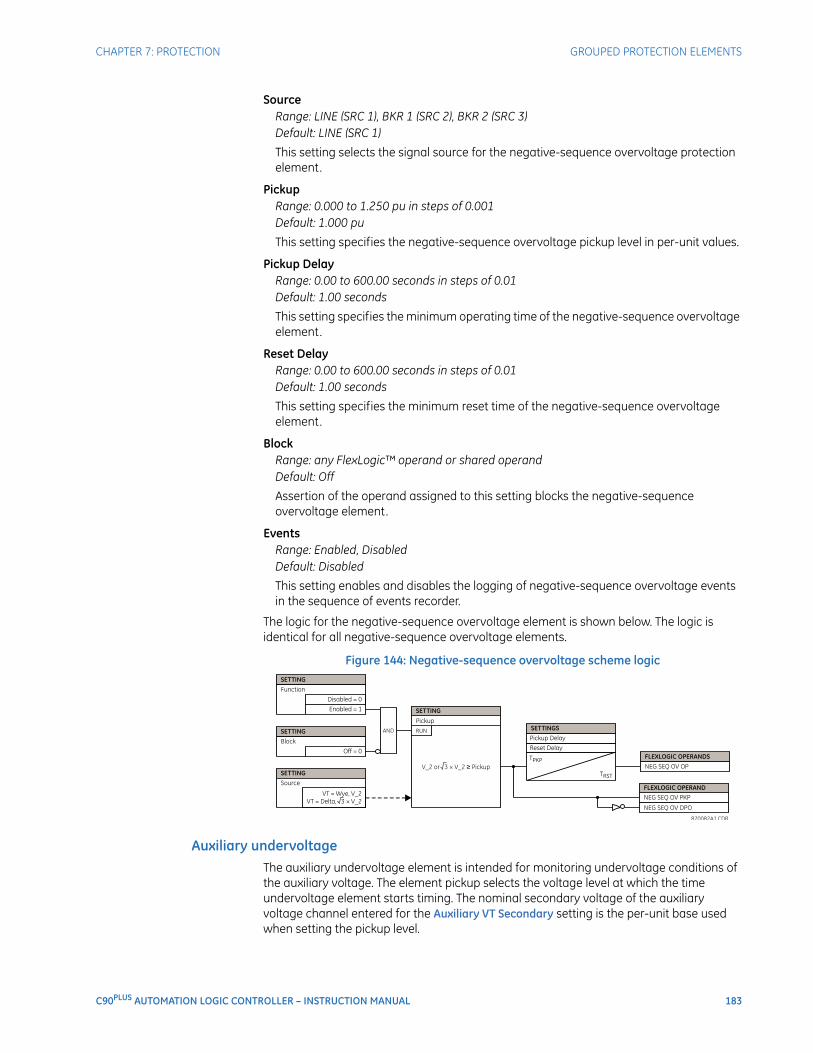
CHAPTER 7: PROTECTION GROUPED PROTECTION ELEMENTS
C90PLUS AUTOMATION LOGIC CONTROLLER – INSTRUCTION MANUAL 183
SourceRange: LINE (SRC 1), BKR 1 (SRC 2), BKR 2 (SRC 3)Default: LINE (SRC 1)
This setting selects the signal source for the negative-sequence overvoltage protection element.
PickupRange: 0.000 to 1.250 pu in steps of 0.001Default: 1.000 pu
This setting specifies the negative-sequence overvoltage pickup level in per-unit values.
Pickup DelayRange: 0.00 to 600.00 seconds in steps of 0.01Default: 1.00 seconds
This setting specifies the minimum operating time of the negative-sequence overvoltage element.
Reset DelayRange: 0.00 to 600.00 seconds in steps of 0.01Default: 1.00 seconds
This setting specifies the minimum reset time of the negative-sequence overvoltage element.
BlockRange: any FlexLogic™ operand or shared operandDefault: Off
Assertion of the operand assigned to this setting blocks the negative-sequence overvoltage element.
EventsRange: Enabled, DisabledDefault: Disabled
This setting enables and disables the logging of negative-sequence overvoltage events in the sequence of events recorder.
The logic for the negative-sequence overvoltage element is shown below. The logic is identical for all negative-sequence overvoltage elements.
Figure 144: Negative-sequence overvoltage scheme logic
Auxiliary undervoltageThe auxiliary undervoltage element is intended for monitoring undervoltage conditions of the auxiliary voltage. The element pickup selects the voltage level at which the time undervoltage element starts timing. The nominal secondary voltage of the auxiliary voltage channel entered for the Auxiliary VT Secondary setting is the per-unit base used when setting the pickup level.
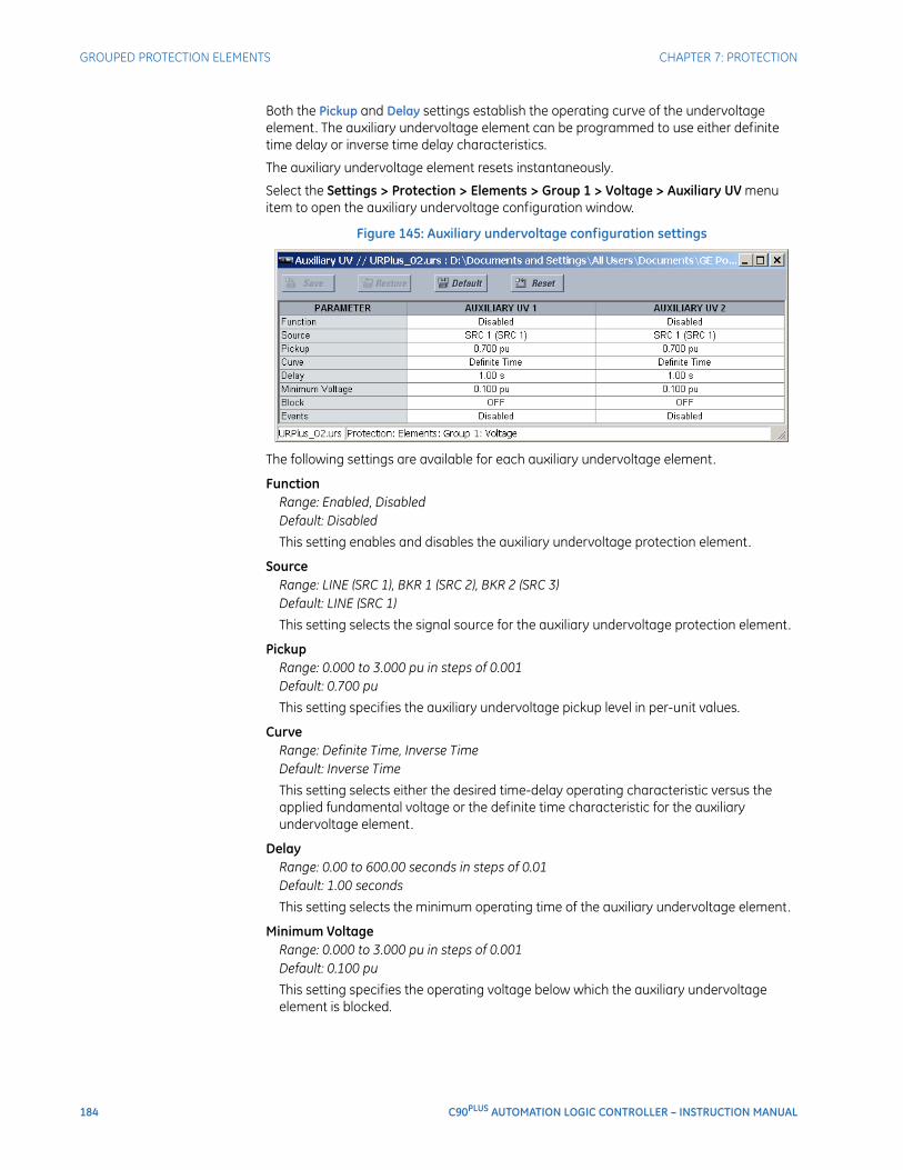
184 C90PLUS AUTOMATION LOGIC CONTROLLER – INSTRUCTION MANUAL
GROUPED PROTECTION ELEMENTS CHAPTER 7: PROTECTION
Both the Pickup and Delay settings establish the operating curve of the undervoltage element. The auxiliary undervoltage element can be programmed to use either definite time delay or inverse time delay characteristics.
The auxiliary undervoltage element resets instantaneously.
Select the Settings > Protection > Elements > Group 1 > Voltage > Auxiliary UV menu item to open the auxiliary undervoltage configuration window.
Figure 145: Auxiliary undervoltage configuration settings
The following settings are available for each auxiliary undervoltage element.
FunctionRange: Enabled, DisabledDefault: Disabled
This setting enables and disables the auxiliary undervoltage protection element.
SourceRange: LINE (SRC 1), BKR 1 (SRC 2), BKR 2 (SRC 3)Default: LINE (SRC 1)
This setting selects the signal source for the auxiliary undervoltage protection element.
PickupRange: 0.000 to 3.000 pu in steps of 0.001Default: 0.700 pu
This setting specifies the auxiliary undervoltage pickup level in per-unit values.
CurveRange: Definite Time, Inverse TimeDefault: Inverse Time
This setting selects either the desired time-delay operating characteristic versus the applied fundamental voltage or the definite time characteristic for the auxiliary undervoltage element.
DelayRange: 0.00 to 600.00 seconds in steps of 0.01Default: 1.00 seconds
This setting selects the minimum operating time of the auxiliary undervoltage element.
Minimum VoltageRange: 0.000 to 3.000 pu in steps of 0.001Default: 0.100 pu
This setting specifies the operating voltage below which the auxiliary undervoltage element is blocked.
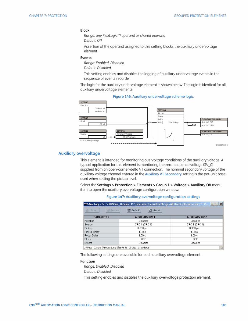
CHAPTER 7: PROTECTION GROUPED PROTECTION ELEMENTS
C90PLUS AUTOMATION LOGIC CONTROLLER – INSTRUCTION MANUAL 185
BlockRange: any FlexLogic™ operand or shared operandDefault: Off
Assertion of the operand assigned to this setting blocks the auxiliary undervoltage element.
EventsRange: Enabled, DisabledDefault: Disabled
This setting enables and disables the logging of auxiliary undervoltage events in the sequence of events recorder.
The logic for the auxiliary undervoltage element is shown below. The logic is identical for all auxiliary undervoltage elements.
Figure 146: Auxiliary undervoltage scheme logic
Auxiliary overvoltageThis element is intended for monitoring overvoltage conditions of the auxiliary voltage. A typical application for this element is monitoring the zero-sequence voltage (3V_0) supplied from an open-corner-delta VT connection. The nominal secondary voltage of the auxiliary voltage channel entered in the Auxiliary VT Secondary setting is the per-unit base used when setting the pickup level.
Select the Settings > Protection > Elements > Group 1 > Voltage > Auxiliary OV menu item to open the auxiliary overvoltage configuration window.
Figure 147: Auxiliary overvoltage configuration settings
The following settings are available for each auxiliary overvoltage element.
FunctionRange: Enabled, DisabledDefault: Disabled
This setting enables and disables the auxiliary overvoltage protection element.
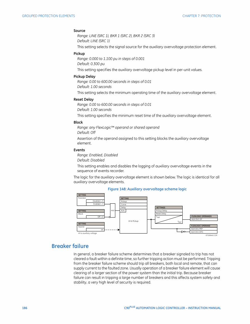
186 C90PLUS AUTOMATION LOGIC CONTROLLER – INSTRUCTION MANUAL
GROUPED PROTECTION ELEMENTS CHAPTER 7: PROTECTION
SourceRange: LINE (SRC 1), BKR 1 (SRC 2), BKR 2 (SRC 3)Default: LINE (SRC 1)
This setting selects the signal source for the auxiliary overvoltage protection element.
PickupRange: 0.000 to 1.100 pu in steps of 0.001Default: 0.300 pu
This setting specifies the auxiliary overvoltage pickup level in per-unit values.
Pickup DelayRange: 0.00 to 600.00 seconds in steps of 0.01Default: 1.00 seconds
This setting selects the minimum operating time of the auxiliary overvoltage element.
Reset DelayRange: 0.00 to 600.00 seconds in steps of 0.01Default: 1.00 seconds
This setting specifies the minimum reset time of the auxiliary overvoltage element.
BlockRange: any FlexLogic™ operand or shared operandDefault: Off
Assertion of the operand assigned to this setting blocks the auxiliary overvoltage element.
EventsRange: Enabled, DisabledDefault: Disabled
This setting enables and disables the logging of auxiliary overvoltage events in the sequence of events recorder.
The logic for the auxiliary overvoltage element is shown below. The logic is identical for all auxiliary overvoltage elements.
Figure 148: Auxiliary overvoltage scheme logic
Breaker failureIn general, a breaker failure scheme determines that a breaker signaled to trip has not cleared a fault within a definite time, so further tripping action must be performed. Tripping from the breaker failure scheme should trip all breakers, both local and remote, that can supply current to the faulted zone. Usually operation of a breaker failure element will cause clearing of a larger section of the power system than the initial trip. Because breaker failure can result in tripping a large number of breakers and this affects system safety and stability, a very high level of security is required.
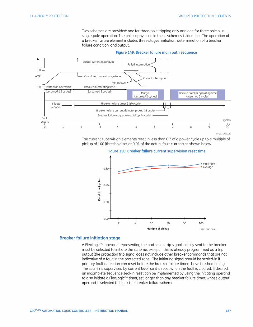
CHAPTER 7: PROTECTION GROUPED PROTECTION ELEMENTS
C90PLUS AUTOMATION LOGIC CONTROLLER – INSTRUCTION MANUAL 187
Two schemes are provided: one for three-pole tripping only and one for three pole plus single-pole operation. The philosophy used in these schemes is identical. The operation of a breaker failure element includes three stages: initiation, determination of a breaker failure condition, and output.
Figure 149: Breaker failure main path sequence
The current supervision elements reset in less than 0.7 of a power cycle up to a multiple of pickup of 100 (threshold set at 0.01 of the actual fault current) as shown below.
Figure 150: Breaker failure current supervision reset time
Breaker failure initiation stageA FlexLogic™ operand representing the protection trip signal initially sent to the breaker must be selected to initiate the scheme, except if this is already programmed as a trip output (the protection trip signal does not include other breaker commands that are not indicative of a fault in the protected zone). The initiating signal should be sealed-in if primary fault detection can reset before the breaker failure timers have finished timing. The seal-in is supervised by current level, so it is reset when the fault is cleared. If desired, an incomplete sequence seal-in reset can be implemented by using the initiating operand to also initiate a FlexLogic™ timer, set longer than any breaker failure timer, whose output operand is selected to block the breaker failure scheme.

188 C90PLUS AUTOMATION LOGIC CONTROLLER – INSTRUCTION MANUAL
GROUPED PROTECTION ELEMENTS CHAPTER 7: PROTECTION
Schemes can be initiated either directly or with current level supervision. It is particularly important in any application to decide if a current-supervised initiate is to be used. The use of a current-supervised initiate results in the breaker failure element not being initiated for a breaker that has very little or no current flowing through it, which may be the case for transformer faults. For those situations where it is required to maintain breaker fail coverage for fault levels below the Phase Current Supv Pickup or the Neutral Current Supv Pickup setting, a current supervised initiate should not be used. This feature should be utilized for those situations where coordinating margins may be reduced when high speed reclosing is used. Thus, if this choice is made, fault levels must always be above the supervision pickup levels for dependable operation of the breaker fail scheme. This can also occur in breaker-and-a-half or ring bus configurations where the first breaker closes into a fault; the protection trips and attempts to initiate breaker failure for the second breaker, which is in the process of closing, but does not yet have current flowing through it .
When the scheme is initiated, it immediately sends a trip signal to the breaker initially signaled to trip (this feature is usually described as re-trip). This reduces the possibility of widespread tripping that results from a declaration of a failed breaker.
Determination of a breaker failure conditionThe schemes determine a breaker failure condition via three paths. Each of these paths is equipped with a time delay, after which a failed breaker is declared and trip signals are sent to all breakers required to clear the zone. The delayed paths are associated with breaker failure timers 1, 2, and 3, which are intended to have delays increasing with increasing timer numbers. These delayed paths are individually enabled to allow for maximum flexibility.
Timer 1 logic (early path) is supervised by a fast-operating breaker auxiliary contact. If the breaker is still closed (as indicated by the auxiliary contact) and fault current is detected after the delay interval, an output is issued. Operation of the breaker auxiliary switch indicates that the breaker has mechanically operated. The continued presence of current indicates that the breaker has failed to interrupt the circuit.
Timer 2 logic (main path) is not supervised by a breaker auxiliary contact. If fault current is detected after the delay interval, an output is issued. This path is intended to detect a breaker that opens mechanically but fails to interrupt fault current; the logic therefore does not use a breaker auxiliary contact.
The timer 1 and 2 paths provide two levels of current supervision, high-set and low-set, that allow the supervision level to change from a current which flows before a breaker inserts an opening resistor into the faulted circuit to a lower level after resistor insertion. The high-set detector is enabled after timeout of timer 1 or 2, along with a timer that will enable the low-set detector after its delay interval. The delay interval between high-set and low-set is the expected breaker opening time. Both current detectors provide a fast operating time for currents at small multiples of the pickup value. The overcurrent detectors are required to operate after the breaker failure delay interval to eliminate the need for very fast resetting overcurrent detectors.
Timer 3 logic (slow path) is supervised by a breaker auxiliary contact and a control switch contact used to indicate that the breaker is in/out of service, disabling this path when the breaker is out of service for maintenance. There is no current level check in this logic as it is intended to detect low magnitude faults and it is therefore the slowest to operate.
Breaker failure scheme outputsThe outputs from the breaker failure scheme are:
• FlexLogic™ operands that report on the operation of portions of the scheme.
• A FlexLogic™ operand used to re-trip the protected breaker.
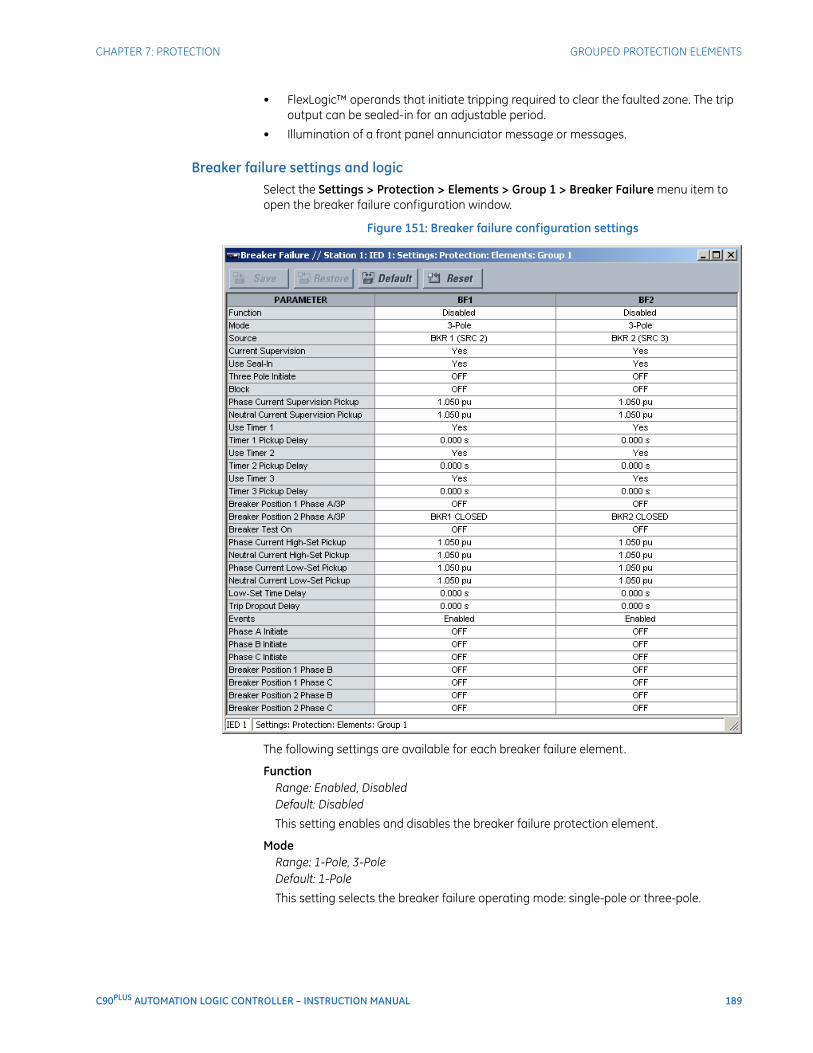
CHAPTER 7: PROTECTION GROUPED PROTECTION ELEMENTS
C90PLUS AUTOMATION LOGIC CONTROLLER – INSTRUCTION MANUAL 189
• FlexLogic™ operands that initiate tripping required to clear the faulted zone. The trip output can be sealed-in for an adjustable period.
• Illumination of a front panel annunciator message or messages.
Breaker failure settings and logicSelect the Settings > Protection > Elements > Group 1 > Breaker Failure menu item to open the breaker failure configuration window.
Figure 151: Breaker failure configuration settings
The following settings are available for each breaker failure element.
FunctionRange: Enabled, DisabledDefault: Disabled
This setting enables and disables the breaker failure protection element.
ModeRange: 1-Pole, 3-PoleDefault: 1-Pole
This setting selects the breaker failure operating mode: single-pole or three-pole.

190 C90PLUS AUTOMATION LOGIC CONTROLLER – INSTRUCTION MANUAL
GROUPED PROTECTION ELEMENTS CHAPTER 7: PROTECTION
SourceRange: LINE (SRC 1), BKR 1 (SRC 2), BKR 2 (SRC 3)Default: LINE (SRC 1)
This setting selects the signal source for the breaker failure protection element.
Current SupervisionRange: Yes, NoDefault: Yes
If set to “Yes”, the breaker failure element will only be initiated if current flowing through the breaker is above the supervision pickup level.
Use Seal-InRange: Yes, NoDefault: Yes
If set to “Yes”, the breaker failure element will only be sealed-in if current flowing through the breaker is above the supervision pickup level.
Three Pole InitiateRange: any FlexLogic™ operand or shared operandDefault: Off
This setting selects the operand that will initiate three-pole tripping of the breaker when asserted.
BlockRange: any FlexLogic™ operand or shared operandDefault: Off
Assertion of the operand assigned to this setting blocks operation of the breaker failure element.
Phase Current Supervision PickupRange: 0.001 to 30.000 pu in steps of 0.001Default: 1.050 pu
This setting specifies the phase current initiation and seal-in supervision level. Generally, this setting should detect the lowest expected fault current on the protected breaker. It can be set as low as necessary (lower than breaker resistor current or lower than load current). High-set and low-set current supervision will ensure correct operation.
Neutral Current Supervision PickupRange: 0.001 to 30.000 pu in steps of 0.001Default: 1.050 pu
This setting specifies the neutral current initiate and seal-in supervision level. Generally, this setting should detect the lowest expected fault current on the protected breaker. Neutral current supervision is used only in the three phase scheme to provide increased sensitivity. This setting is valid only for three-pole tripping schemes.
Use Timer 1Range: Yes, NoDefault: Yes
If this setting value is “Yes”, the early path is operational.
Timer 1 Pickup DelayRange: 0.000 to 65.535 seconds in steps of 0.001Default: 0 seconds
Timer 1 is set to the shortest time required for breaker auxiliary contact Status-1 to open, from the time the initial trip signal is applied to the breaker trip circuit, plus a safety margin.

CHAPTER 7: PROTECTION GROUPED PROTECTION ELEMENTS
C90PLUS AUTOMATION LOGIC CONTROLLER – INSTRUCTION MANUAL 191
Use Timer 2Range: Yes, NoDefault: Yes
If this setting value is “Yes”, the main path is operational.
Timer 2 Pickup DelayRange: 0.000 to 65.535 seconds in steps of 0.001Default: 0 seconds
Timer 2 is set to the expected opening time of the breaker, plus a safety margin. This safety margin was historically intended to allow for measuring and timing errors in the breaker failure scheme equipment. In microprocessor relays this time is not significant. In the URPlus-series devices, which use a Fourier transform, the calculated current magnitude will ramp-down to zero one power frequency cycle after the current is interrupted, and this lag should be included in the overall margin duration, as it occurs after current interruption. The breaker failure main path sequence diagram shows a margin of two cycles; this interval is considered the minimum appropriate for most applications.
In bulk oil circuit breakers, the interrupting time for currents less than 25% of the interrupting rating can be significantly longer than the normal interrupting time.
Use Timer 3Range: Yes, NoDefault: Yes
If this setting value is “Yes”, the slow path is operational.
Timer 3 Pickup DelayRange: 0.000 to 65.535 seconds in steps of 0.001Default: 0 seconds
Timer 3 is set to the same interval as timer 2, plus an increased safety margin. Because this path is intended to operate only for low level faults, the delay can be in the order of 300 to 500 ms.
Breaker Position 1 Phase A/3PRange: any FlexLogic™ operand or shared operandDefault: Off
This setting selects the operand that represents the protected breaker early-type auxiliary switch contact (52/a). When using the single-pole breaker failure scheme, this operand represents the protected breaker early-type auxiliary switch contact on pole A. This is normally a non-multiplied form-A contact. The contact may even be adjusted to have the shortest possible operating time.
Breaker Position 2 Phase A/3PRange: any FlexLogic™ operand or shared operandDefault: Off
This setting selects the operand that represents the breaker normal-type auxiliary switch contact (52/a). When using the single-pole breaker failure scheme, this operand represents the protected breaker auxiliary switch contact on pole A. This may be a multiplied contact.
Breaker Test OnRange: any FlexLogic™ operand or shared operandDefault: Off
This setting selects the operand that represents the breaker in-service/out-of-service switch set to the out-of-service position.

192 C90PLUS AUTOMATION LOGIC CONTROLLER – INSTRUCTION MANUAL
GROUPED PROTECTION ELEMENTS CHAPTER 7: PROTECTION
Phase Current High-Set PickupRange: 0.001 to 30.000 pu in steps of 0.001Default: 1.050 pu
This setting specifies the phase current output supervision level. Generally, this setting should detect the lowest expected fault current on the protected breaker, before a breaker opening resistor is inserted.
Neutral Current High-Set PickupRange: 0.001 to 30.000 pu in steps of 0.001Default: 1.050 pu
This setting specifies the neutral current output supervision level. Generally, this setting should detect the lowest expected fault current on the protected breaker, before a breaker opening resistor is inserted. Neutral current supervision is used only in the three pole scheme to provide increased sensitivity. This setting is valid only for three-pole breaker failure schemes.
Phase Current Low-Set PickupRange: 0.001 to 30.000 pu in steps of 0.001Default: 1.050 pu
This setting specifies the phase current output supervision level. Generally, this setting should detect the lowest expected fault current on the protected breaker, after a breaker opening resistor is inserted (approximately 90% of the resistor current).
Neutral Current Low-Set PickupRange: 0.001 to 30.000 pu in steps of 0.001Default: 1.050 pu
This setting specifies the neutral current output supervision level. Generally, this setting should detect the lowest expected fault current on the protected breaker, after a breaker opening resistor is inserted (approximately 90% of the resistor current). This setting is valid only for three-pole breaker failure schemes.
Low-Set Time DelayRange: 0.000 to 65.535 seconds in steps of 0.001Default: 0.000 seconds
This setting specifies the pickup delay for current detection after opening resistor insertion.
Trip Dropout DelayRange: 0.000 to 65.535 seconds in steps of 0.001Default: 0.000 seconds
This setting specifies the time for which the trip output is sealed-in. This timer must be coordinated with the automatic reclosing scheme of the failed breaker, to which the breaker failure element sends a cancel reclosure signal. Reclosure of a remote breaker can also be prevented by holding a transfer trip signal on longer than the reclaim time.
EventsRange: Enabled, DisabledDefault: Enabled
This setting enables and disables the logging of breaker failure events in the sequence of events recorder.
Phase A Initiate, Phase B Initiate, Phase C InitiateRange: any FlexLogic™ operand or shared operandDefault: Off
These settings select operands to initiate phase A, B, and C single-pole tripping of the breaker and the phase A, B, or C portion of the scheme, accordingly. These settings are only valid for single-pole breaker failure schemes.

CHAPTER 7: PROTECTION GROUPED PROTECTION ELEMENTS
C90PLUS AUTOMATION LOGIC CONTROLLER – INSTRUCTION MANUAL 193
Breaker Position 1 Phase BRange: any FlexLogic™ operand or shared operandDefault: Off
This setting selects the operand to represent the protected breaker early-type auxiliary switch contact on pole B. This contact is normally a non-multiplied form-A contact. The contact may even be adjusted to have the shortest possible operating time. This setting is valid only for single-pole breaker failure schemes.
Breaker Position 1 Phase CRange: any FlexLogic™ operand or shared operandDefault: Off
This setting selects the operand to represent the protected breaker early-type auxiliary switch contact on pole C. This contact is normally a non-multiplied form-A contact. The contact may even be adjusted to have the shortest possible operating time. This setting is valid only for single-pole breaker failure schemes.
Breaker Position 2 Phase BRange: any FlexLogic™ operand or shared operandDefault: Off
This setting selects the operand that represents the protected breaker normal-type auxiliary switch contact on pole B (52/a). This may be a multiplied contact. This setting is valid only for single-pole breaker failure schemes.
Breaker Position 2 Phase CRange: any FlexLogic™ operand or shared operandDefault: Off
This setting selects the operand that represents the protected breaker normal-type auxiliary switch contact on pole C (52/a). This may be a multiplied contact. For single-pole operation, the scheme has the same overall general concept except that it provides re-tripping of each single pole of the protected breaker. The approach shown in the following single pole tripping diagram uses the initiating information to determine which pole is supposed to trip. The logic is segregated on a per-pole basis. The overcurrent detectors have ganged settings. This setting is valid only for single-pole breaker failure schemes.
Upon operation of the breaker failure element for a single pole trip command, a three-pole trip command should be given via the BKR FAIL 1 TRIP OP output operand.
The logic for the breaker failure element is shown in the following figures. The logic is identical for both breaker failure elements.
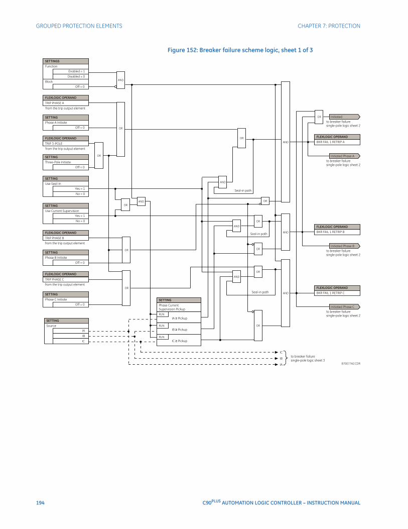
194 C90PLUS AUTOMATION LOGIC CONTROLLER – INSTRUCTION MANUAL
GROUPED PROTECTION ELEMENTS CHAPTER 7: PROTECTION
Figure 152: Breaker failure scheme logic, sheet 1 of 3
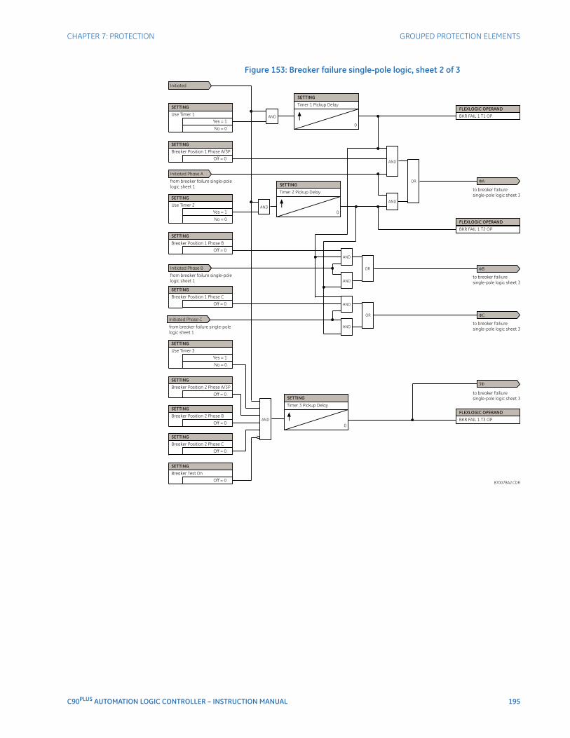
CHAPTER 7: PROTECTION GROUPED PROTECTION ELEMENTS
C90PLUS AUTOMATION LOGIC CONTROLLER – INSTRUCTION MANUAL 195
Figure 153: Breaker failure single-pole logic, sheet 2 of 3
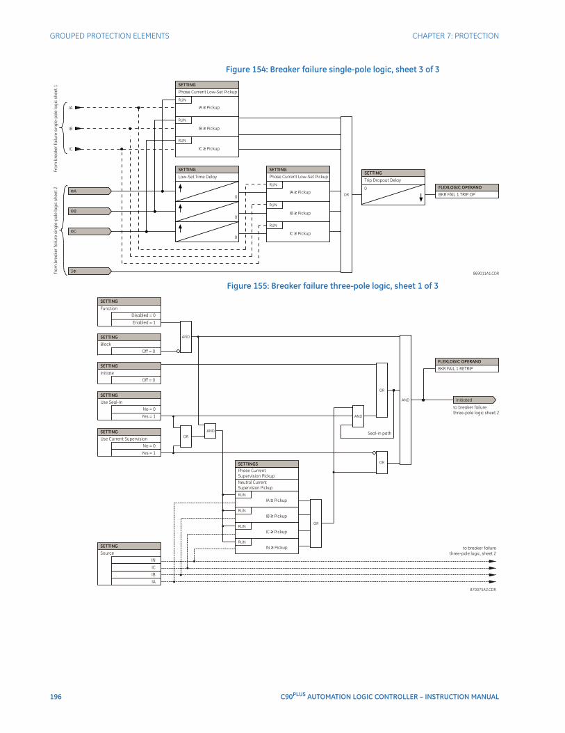
196 C90PLUS AUTOMATION LOGIC CONTROLLER – INSTRUCTION MANUAL
GROUPED PROTECTION ELEMENTS CHAPTER 7: PROTECTION
Figure 154: Breaker failure single-pole logic, sheet 3 of 3
Figure 155: Breaker failure three-pole logic, sheet 1 of 3
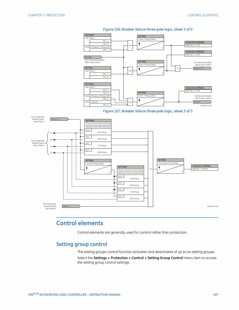
CHAPTER 7: PROTECTION CONTROL ELEMENTS
C90PLUS AUTOMATION LOGIC CONTROLLER – INSTRUCTION MANUAL 197
Figure 156: Breaker failure three-pole logic, sheet 2 of 3
Figure 157: Breaker failure three-pole logic, sheet 3 of 3
Control elementsControl elements are generally used for control rather than protection.
Setting group controlThe setting groups control function activates and deactivates of up to six setting groups.
Select the Settings > Protection > Control > Setting Group Control menu item to access the setting group control settings.
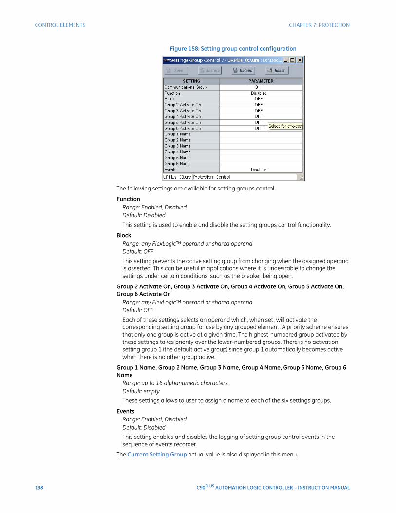
198 C90PLUS AUTOMATION LOGIC CONTROLLER – INSTRUCTION MANUAL
CONTROL ELEMENTS CHAPTER 7: PROTECTION
Figure 158: Setting group control configuration
The following settings are available for setting groups control.
FunctionRange: Enabled, DisabledDefault: Disabled
This setting is used to enable and disable the setting groups control functionality.
BlockRange: any FlexLogic™ operand or shared operandDefault: OFF
This setting prevents the active setting group from changing when the assigned operand is asserted. This can be useful in applications where it is undesirable to change the settings under certain conditions, such as the breaker being open.
Group 2 Activate On, Group 3 Activate On, Group 4 Activate On, Group 5 Activate On, Group 6 Activate On
Range: any FlexLogic™ operand or shared operandDefault: OFF
Each of these settings selects an operand which, when set, will activate the corresponding setting group for use by any grouped element. A priority scheme ensures that only one group is active at a given time. The highest-numbered group activated by these settings takes priority over the lower-numbered groups. There is no activation setting group 1 (the default active group) since group 1 automatically becomes active when there is no other group active.
Group 1 Name, Group 2 Name, Group 3 Name, Group 4 Name, Group 5 Name, Group 6 Name
Range: up to 16 alphanumeric charactersDefault: empty
These settings allows to user to assign a name to each of the six settings groups.
EventsRange: Enabled, DisabledDefault: Disabled
This setting enables and disables the logging of setting group control events in the sequence of events recorder.
The Current Setting Group actual value is also displayed in this menu.
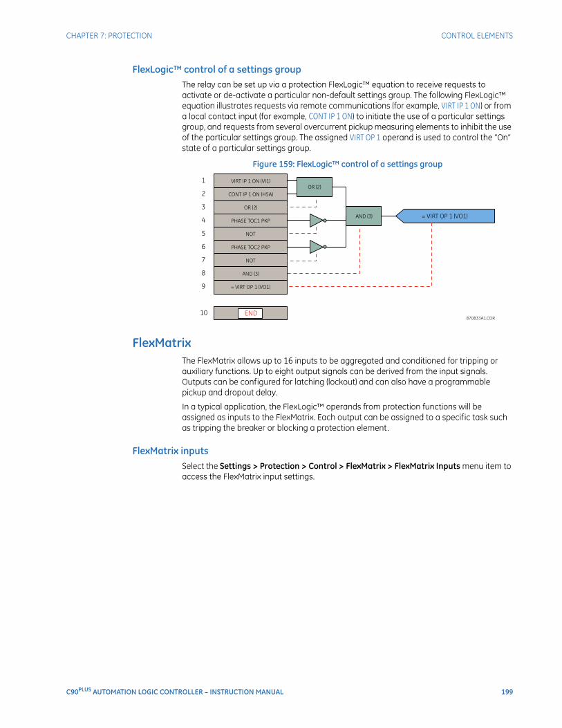
CHAPTER 7: PROTECTION CONTROL ELEMENTS
C90PLUS AUTOMATION LOGIC CONTROLLER – INSTRUCTION MANUAL 199
FlexLogic™ control of a settings groupThe relay can be set up via a protection FlexLogic™ equation to receive requests to activate or de-activate a particular non-default settings group. The following FlexLogic™ equation illustrates requests via remote communications (for example, VIRT IP 1 ON) or from a local contact input (for example, CONT IP 1 ON) to initiate the use of a particular settings group, and requests from several overcurrent pickup measuring elements to inhibit the use of the particular settings group. The assigned VIRT OP 1 operand is used to control the “On” state of a particular settings group.
Figure 159: FlexLogic™ control of a settings group
FlexMatrixThe FlexMatrix allows up to 16 inputs to be aggregated and conditioned for tripping or auxiliary functions. Up to eight output signals can be derived from the input signals. Outputs can be configured for latching (lockout) and can also have a programmable pickup and dropout delay.
In a typical application, the FlexLogic™ operands from protection functions will be assigned as inputs to the FlexMatrix. Each output can be assigned to a specific task such as tripping the breaker or blocking a protection element.
FlexMatrix inputsSelect the Settings > Protection > Control > FlexMatrix > FlexMatrix Inputs menu item to access the FlexMatrix input settings.

200 C90PLUS AUTOMATION LOGIC CONTROLLER – INSTRUCTION MANUAL
CONTROL ELEMENTS CHAPTER 7: PROTECTION
Figure 160: FlexMatrix input configuration settings
The following setting is available for each of the 16 FlexMatrix inputs.
Input 1, Input 2,..., Input 16Range: any FlexLogic™ operand or shared operandDefault: OFF
The operand assigned to this setting can be re-assigned to any or all of the FlexMatrix outputs.
FlexMatrix configurationSelect the Settings > Protection > Control > FlexMatrix > FlexMatrix menu item to access the FlexMatrix configuration settings.
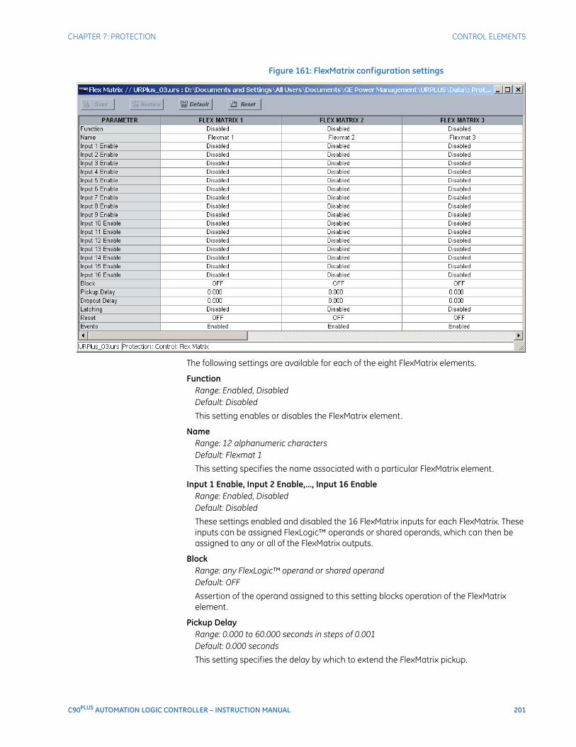
CHAPTER 7: PROTECTION CONTROL ELEMENTS
C90PLUS AUTOMATION LOGIC CONTROLLER – INSTRUCTION MANUAL 201
Figure 161: FlexMatrix configuration settings
The following settings are available for each of the eight FlexMatrix elements.
FunctionRange: Enabled, DisabledDefault: Disabled
This setting enables or disables the FlexMatrix element.
NameRange: 12 alphanumeric charactersDefault: Flexmat 1
This setting specifies the name associated with a particular FlexMatrix element.
Input 1 Enable, Input 2 Enable,..., Input 16 EnableRange: Enabled, DisabledDefault: Disabled
These settings enabled and disabled the 16 FlexMatrix inputs for each FlexMatrix. These inputs can be assigned FlexLogic™ operands or shared operands, which can then be assigned to any or all of the FlexMatrix outputs.
BlockRange: any FlexLogic™ operand or shared operandDefault: OFF
Assertion of the operand assigned to this setting blocks operation of the FlexMatrix element.
Pickup DelayRange: 0.000 to 60.000 seconds in steps of 0.001Default: 0.000 seconds
This setting specifies the delay by which to extend the FlexMatrix pickup.
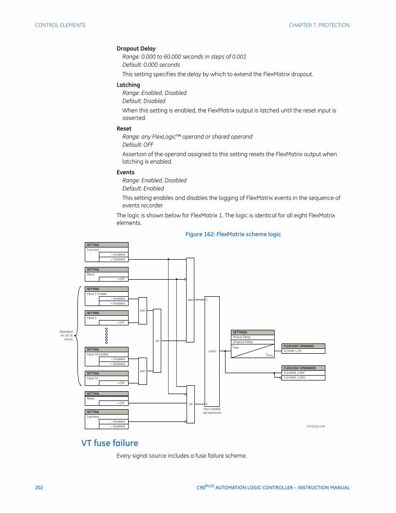
202 C90PLUS AUTOMATION LOGIC CONTROLLER – INSTRUCTION MANUAL
CONTROL ELEMENTS CHAPTER 7: PROTECTION
Dropout DelayRange: 0.000 to 60.000 seconds in steps of 0.001Default: 0.000 seconds
This setting specifies the delay by which to extend the FlexMatrix dropout.
LatchingRange: Enabled, DisabledDefault: Disabled
When this setting is enabled, the FlexMatrix output is latched until the reset input is asserted.
ResetRange: any FlexLogic™ operand or shared operandDefault: OFF
Assertion of the operand assigned to this setting resets the FlexMatrix output when latching is enabled.
EventsRange: Enabled, DisabledDefault: Enabled
This setting enables and disables the logging of FlexMatrix events in the sequence of events recorder.
The logic is shown below for FlexMatrix 1. The logic is identical for all eight FlexMatrix elements.
Figure 162: FlexMatrix scheme logic
VT fuse failureEvery signal source includes a fuse failure scheme.

CHAPTER 7: PROTECTION CONTROL ELEMENTS
C90PLUS AUTOMATION LOGIC CONTROLLER – INSTRUCTION MANUAL 203
The VT fuse failure detector can be used to raise an alarm or block elements that may operate incorrectly for a full or partial loss of AC potential caused by one or more blown fuses. Some elements that might be blocked (via the Block setting) include voltage restrained overcurrent and directional current.
There are two classes of fuse failure that may occur.
• Class A: loss of one or two phases.
• Class B: loss of all three phases.
Different means of detection are required for each class. An indication of class A failures is a significant level of negative-sequence voltage, whereas an indication of class B failures is when positive-sequence current is present and there is an insignificant amount of positive-sequence voltage. These noted indications of fuse failure could also be present when faults are present on the system, so a means of detecting faults and inhibiting fuse failure declarations during these events is provided. Once the fuse failure condition is declared, it will be sealed-in until the cause that generated it disappears.
An additional condition is introduced to inhibit a fuse failure declaration when the monitored circuit is de-energized; positive-sequence voltage and current are both below threshold levels.
Select the Settings > Protection > Control > VT Fuse Failure menu item to access the VT fuse failure settings.
Figure 163: VT fuse failure configuration settings
The following setting is available for each VT fuse failure element.
FunctionRange: Enabled, DisabledDefault: Disabled
This setting enables and disables the fuse failure feature for each source.
The VT fuse failure logic is shown below.
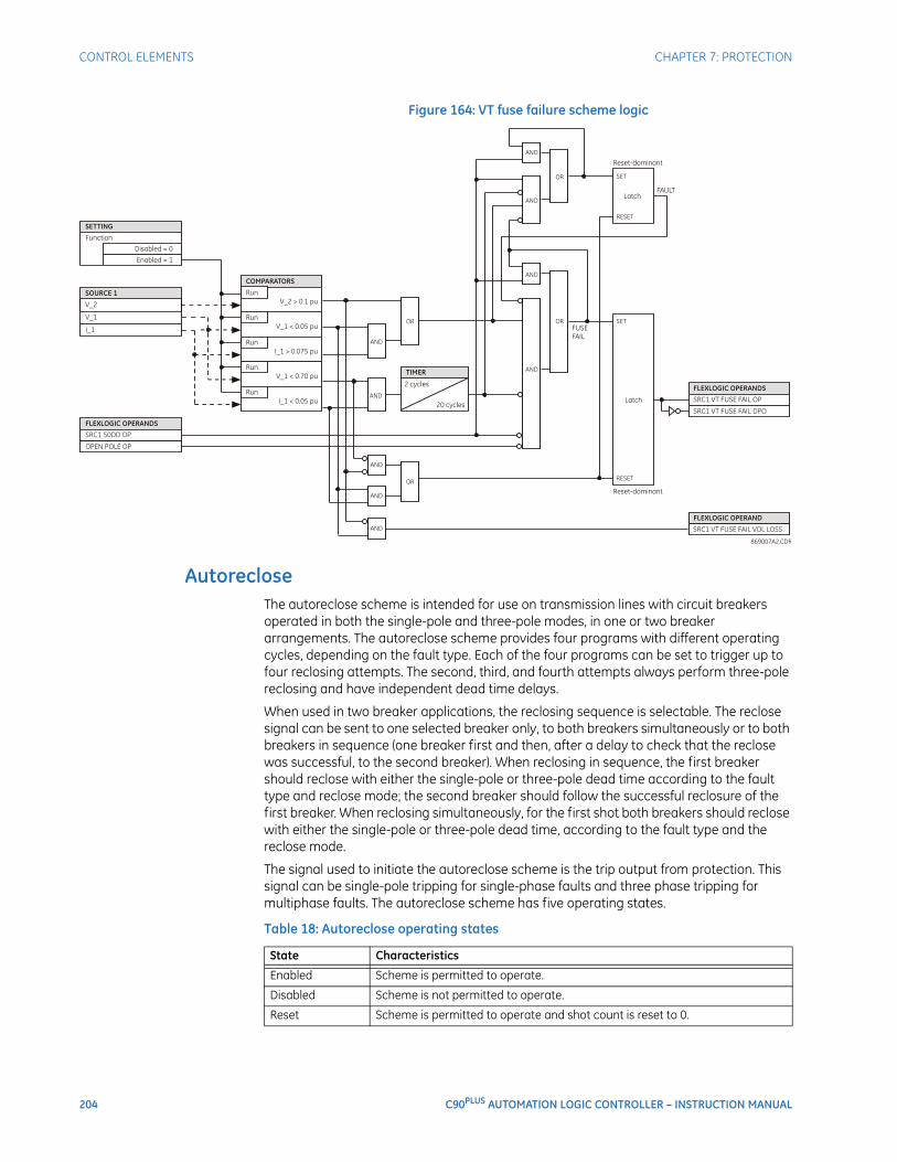
204 C90PLUS AUTOMATION LOGIC CONTROLLER – INSTRUCTION MANUAL
CONTROL ELEMENTS CHAPTER 7: PROTECTION
Figure 164: VT fuse failure scheme logic
AutorecloseThe autoreclose scheme is intended for use on transmission lines with circuit breakers operated in both the single-pole and three-pole modes, in one or two breaker arrangements. The autoreclose scheme provides four programs with different operating cycles, depending on the fault type. Each of the four programs can be set to trigger up to four reclosing attempts. The second, third, and fourth attempts always perform three-pole reclosing and have independent dead time delays.
When used in two breaker applications, the reclosing sequence is selectable. The reclose signal can be sent to one selected breaker only, to both breakers simultaneously or to both breakers in sequence (one breaker first and then, after a delay to check that the reclose was successful, to the second breaker). When reclosing in sequence, the first breaker should reclose with either the single-pole or three-pole dead time according to the fault type and reclose mode; the second breaker should follow the successful reclosure of the first breaker. When reclosing simultaneously, for the first shot both breakers should reclose with either the single-pole or three-pole dead time, according to the fault type and the reclose mode.
The signal used to initiate the autoreclose scheme is the trip output from protection. This signal can be single-pole tripping for single-phase faults and three phase tripping for multiphase faults. The autoreclose scheme has five operating states.
Table 18: Autoreclose operating states
State Characteristics
Enabled Scheme is permitted to operate.
Disabled Scheme is not permitted to operate.
Reset Scheme is permitted to operate and shot count is reset to 0.
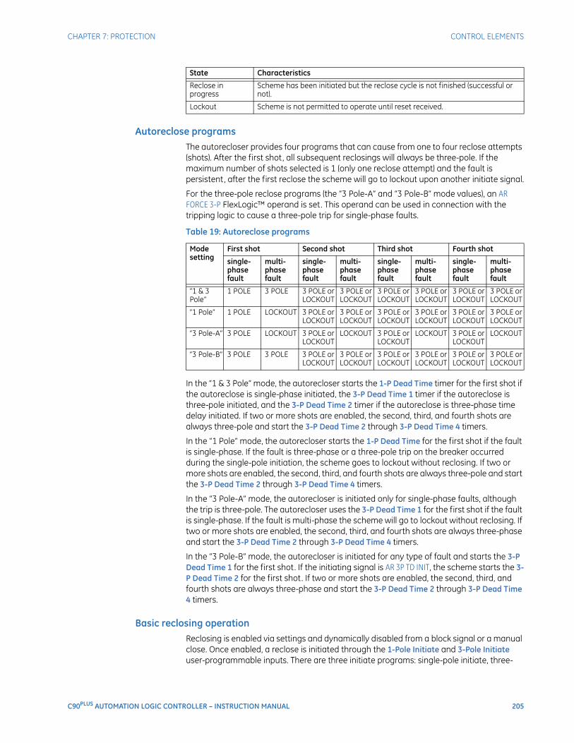
CHAPTER 7: PROTECTION CONTROL ELEMENTS
C90PLUS AUTOMATION LOGIC CONTROLLER – INSTRUCTION MANUAL 205
Autoreclose programsThe autorecloser provides four programs that can cause from one to four reclose attempts (shots). After the first shot, all subsequent reclosings will always be three-pole. If the maximum number of shots selected is 1 (only one reclose attempt) and the fault is persistent, after the first reclose the scheme will go to lockout upon another initiate signal.
For the three-pole reclose programs (the “3 Pole-A” and “3 Pole-B” mode values), an AR FORCE 3-P FlexLogic™ operand is set. This operand can be used in connection with the tripping logic to cause a three-pole trip for single-phase faults.
Table 19: Autoreclose programs
In the “1 & 3 Pole” mode, the autorecloser starts the 1-P Dead Time timer for the first shot if the autoreclose is single-phase initiated, the 3-P Dead Time 1 timer if the autoreclose is three-pole initiated, and the 3-P Dead Time 2 timer if the autoreclose is three-phase time delay initiated. If two or more shots are enabled, the second, third, and fourth shots are always three-pole and start the 3-P Dead Time 2 through 3-P Dead Time 4 timers.
In the “1 Pole” mode, the autorecloser starts the 1-P Dead Time for the first shot if the fault is single-phase. If the fault is three-phase or a three-pole trip on the breaker occurred during the single-pole initiation, the scheme goes to lockout without reclosing. If two or more shots are enabled, the second, third, and fourth shots are always three-pole and start the 3-P Dead Time 2 through 3-P Dead Time 4 timers.
In the “3 Pole-A” mode, the autorecloser is initiated only for single-phase faults, although the trip is three-pole. The autorecloser uses the 3-P Dead Time 1 for the first shot if the fault is single-phase. If the fault is multi-phase the scheme will go to lockout without reclosing. If two or more shots are enabled, the second, third, and fourth shots are always three-phase and start the 3-P Dead Time 2 through 3-P Dead Time 4 timers.
In the “3 Pole-B” mode, the autorecloser is initiated for any type of fault and starts the 3-P Dead Time 1 for the first shot. If the initiating signal is AR 3P TD INIT, the scheme starts the 3-P Dead Time 2 for the first shot. If two or more shots are enabled, the second, third, and fourth shots are always three-phase and start the 3-P Dead Time 2 through 3-P Dead Time 4 timers.
Basic reclosing operationReclosing is enabled via settings and dynamically disabled from a block signal or a manual close. Once enabled, a reclose is initiated through the 1-Pole Initiate and 3-Pole Initiate user-programmable inputs. There are three initiate programs: single-pole initiate, three-
Reclose in progress
Scheme has been initiated but the reclose cycle is not finished (successful or not).
Lockout Scheme is not permitted to operate until reset received.
State Characteristics
Mode setting
First shot Second shot Third shot Fourth shot
single-phase fault
multi-phase fault
single-phase fault
multi-phase fault
single-phase fault
multi-phase fault
single-phase fault
multi-phase fault
“1 & 3 Pole”
1 POLE 3 POLE 3 POLE or LOCKOUT
3 POLE or LOCKOUT
3 POLE or LOCKOUT
3 POLE or LOCKOUT
3 POLE or LOCKOUT
3 POLE or LOCKOUT
“1 Pole” 1 POLE LOCKOUT 3 POLE or LOCKOUT
3 POLE or LOCKOUT
3 POLE or LOCKOUT
3 POLE or LOCKOUT
3 POLE or LOCKOUT
3 POLE or LOCKOUT
“3 Pole-A” 3 POLE LOCKOUT 3 POLE or LOCKOUT
LOCKOUT 3 POLE or LOCKOUT
LOCKOUT 3 POLE or LOCKOUT
LOCKOUT
“3 Pole-B” 3 POLE 3 POLE 3 POLE or LOCKOUT
3 POLE or LOCKOUT
3 POLE or LOCKOUT
3 POLE or LOCKOUT
3 POLE or LOCKOUT
3 POLE or LOCKOUT
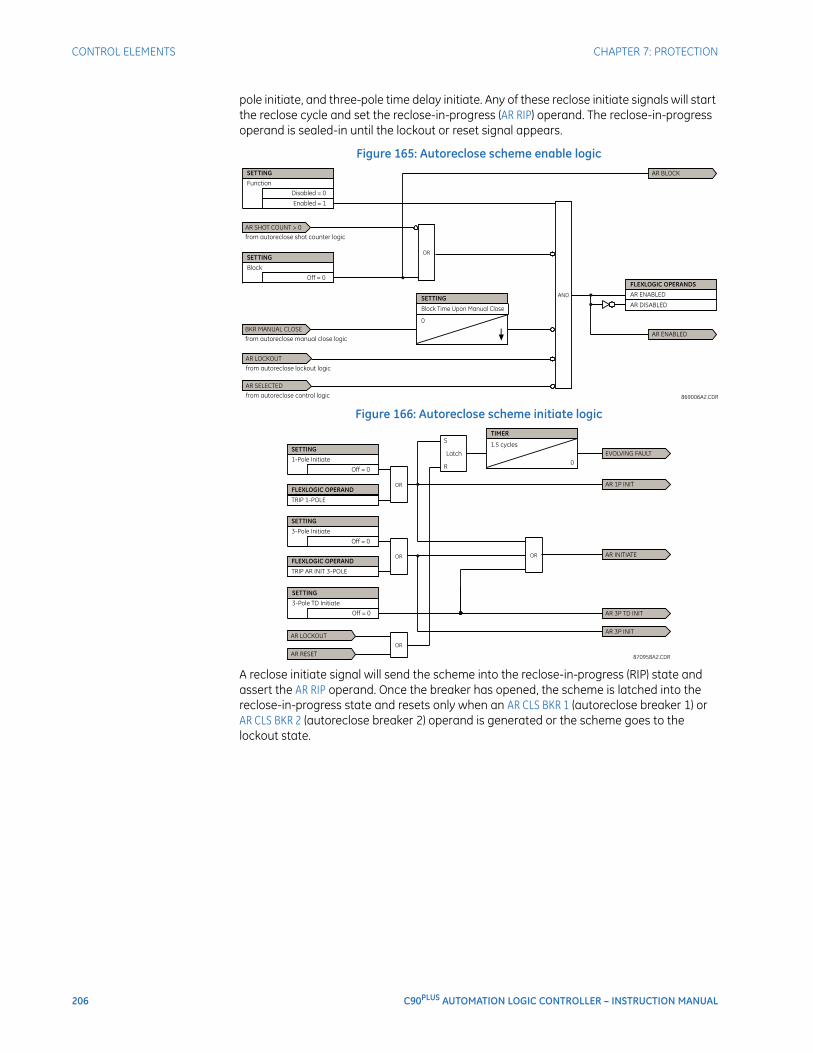
206 C90PLUS AUTOMATION LOGIC CONTROLLER – INSTRUCTION MANUAL
CONTROL ELEMENTS CHAPTER 7: PROTECTION
pole initiate, and three-pole time delay initiate. Any of these reclose initiate signals will start the reclose cycle and set the reclose-in-progress (AR RIP) operand. The reclose-in-progress operand is sealed-in until the lockout or reset signal appears.
Figure 165: Autoreclose scheme enable logic
Figure 166: Autoreclose scheme initiate logic
A reclose initiate signal will send the scheme into the reclose-in-progress (RIP) state and assert the AR RIP operand. Once the breaker has opened, the scheme is latched into the reclose-in-progress state and resets only when an AR CLS BKR 1 (autoreclose breaker 1) or AR CLS BKR 2 (autoreclose breaker 2) operand is generated or the scheme goes to the lockout state.
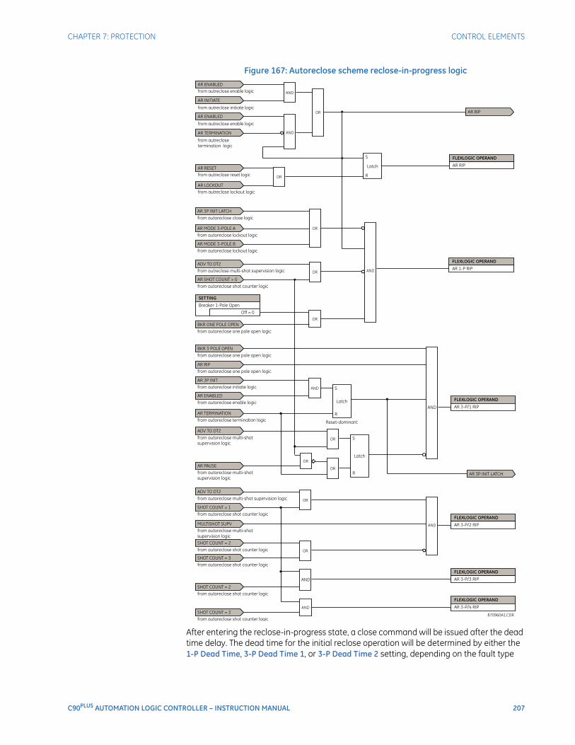
CHAPTER 7: PROTECTION CONTROL ELEMENTS
C90PLUS AUTOMATION LOGIC CONTROLLER – INSTRUCTION MANUAL 207
Figure 167: Autoreclose scheme reclose-in-progress logic
After entering the reclose-in-progress state, a close command will be issued after the dead time delay. The dead time for the initial reclose operation will be determined by either the 1-P Dead Time, 3-P Dead Time 1, or 3-P Dead Time 2 setting, depending on the fault type
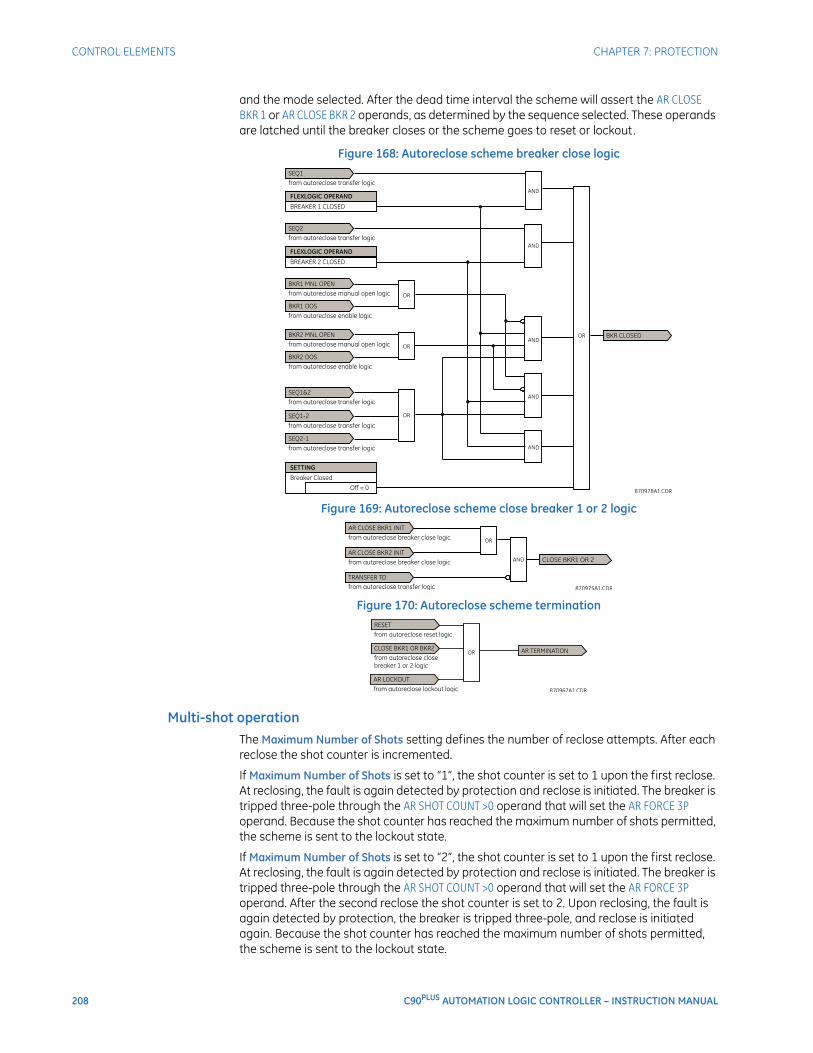
208 C90PLUS AUTOMATION LOGIC CONTROLLER – INSTRUCTION MANUAL
CONTROL ELEMENTS CHAPTER 7: PROTECTION
and the mode selected. After the dead time interval the scheme will assert the AR CLOSE BKR 1 or AR CLOSE BKR 2 operands, as determined by the sequence selected. These operands are latched until the breaker closes or the scheme goes to reset or lockout.
Figure 168: Autoreclose scheme breaker close logic
Figure 169: Autoreclose scheme close breaker 1 or 2 logic
Figure 170: Autoreclose scheme termination
Multi-shot operationThe Maximum Number of Shots setting defines the number of reclose attempts. After each reclose the shot counter is incremented.
If Maximum Number of Shots is set to “1”, the shot counter is set to 1 upon the first reclose. At reclosing, the fault is again detected by protection and reclose is initiated. The breaker is tripped three-pole through the AR SHOT COUNT >0 operand that will set the AR FORCE 3P operand. Because the shot counter has reached the maximum number of shots permitted, the scheme is sent to the lockout state.
If Maximum Number of Shots is set to “2”, the shot counter is set to 1 upon the first reclose. At reclosing, the fault is again detected by protection and reclose is initiated. The breaker is tripped three-pole through the AR SHOT COUNT >0 operand that will set the AR FORCE 3P operand. After the second reclose the shot counter is set to 2. Upon reclosing, the fault is again detected by protection, the breaker is tripped three-pole, and reclose is initiated again. Because the shot counter has reached the maximum number of shots permitted, the scheme is sent to the lockout state.
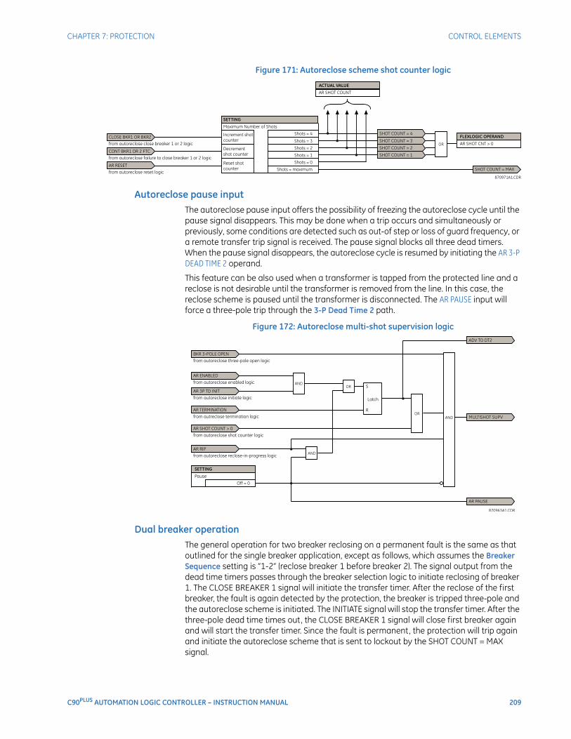
CHAPTER 7: PROTECTION CONTROL ELEMENTS
C90PLUS AUTOMATION LOGIC CONTROLLER – INSTRUCTION MANUAL 209
Figure 171: Autoreclose scheme shot counter logic
Autoreclose pause inputThe autoreclose pause input offers the possibility of freezing the autoreclose cycle until the pause signal disappears. This may be done when a trip occurs and simultaneously or previously, some conditions are detected such as out-of step or loss of guard frequency, or a remote transfer trip signal is received. The pause signal blocks all three dead timers. When the pause signal disappears, the autoreclose cycle is resumed by initiating the AR 3-P DEAD TIME 2 operand.
This feature can be also used when a transformer is tapped from the protected line and a reclose is not desirable until the transformer is removed from the line. In this case, the reclose scheme is paused until the transformer is disconnected. The AR PAUSE input will force a three-pole trip through the 3-P Dead Time 2 path.
Figure 172: Autoreclose multi-shot supervision logic
Dual breaker operationThe general operation for two breaker reclosing on a permanent fault is the same as that outlined for the single breaker application, except as follows, which assumes the Breaker Sequence setting is “1-2” (reclose breaker 1 before breaker 2). The signal output from the dead time timers passes through the breaker selection logic to initiate reclosing of breaker 1. The CLOSE BREAKER 1 signal will initiate the transfer timer. After the reclose of the first breaker, the fault is again detected by the protection, the breaker is tripped three-pole and the autoreclose scheme is initiated. The INITIATE signal will stop the transfer timer. After the three-pole dead time times out, the CLOSE BREAKER 1 signal will close first breaker again and will start the transfer timer. Since the fault is permanent, the protection will trip again and initiate the autoreclose scheme that is sent to lockout by the SHOT COUNT = MAX signal.
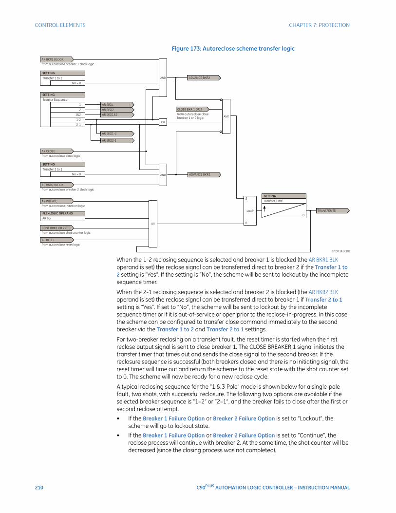
210 C90PLUS AUTOMATION LOGIC CONTROLLER – INSTRUCTION MANUAL
CONTROL ELEMENTS CHAPTER 7: PROTECTION
Figure 173: Autoreclose scheme transfer logic
When the 1-2 reclosing sequence is selected and breaker 1 is blocked (the AR BKR1 BLK operand is set) the reclose signal can be transferred direct to breaker 2 if the Transfer 1 to 2 setting is “Yes”. If the setting is “No”, the scheme will be sent to lockout by the incomplete sequence timer.
When the 2-1 reclosing sequence is selected and breaker 2 is blocked (the AR BKR2 BLK operand is set) the reclose signal can be transferred direct to breaker 1 if Transfer 2 to 1 setting is “Yes”. If set to “No”, the scheme will be sent to lockout by the incomplete sequence timer or if it is out-of-service or open prior to the reclose-in-progress. In this case, the scheme can be configured to transfer close command immediately to the second breaker via the Transfer 1 to 2 and Transfer 2 to 1 settings.
For two-breaker reclosing on a transient fault, the reset timer is started when the first reclose output signal is sent to close breaker 1. The CLOSE BREAKER 1 signal initiates the transfer timer that times out and sends the close signal to the second breaker. If the reclosure sequence is successful (both breakers closed and there is no initiating signal), the reset timer will time out and return the scheme to the reset state with the shot counter set to 0. The scheme will now be ready for a new reclose cycle.
A typical reclosing sequence for the “1 & 3 Pole” mode is shown below for a single-pole fault, two shots, with successful reclosure. The following two options are available if the selected breaker sequence is “1–2” or “2–1”, and the breaker fails to close after the first or second reclose attempt.
• If the Breaker 1 Failure Option or Breaker 2 Failure Option is set to “Lockout”, the scheme will go to lockout state.
• If the Breaker 1 Failure Option or Breaker 2 Failure Option is set to “Continue”, the reclose process will continue with breaker 2. At the same time, the shot counter will be decreased (since the closing process was not completed).
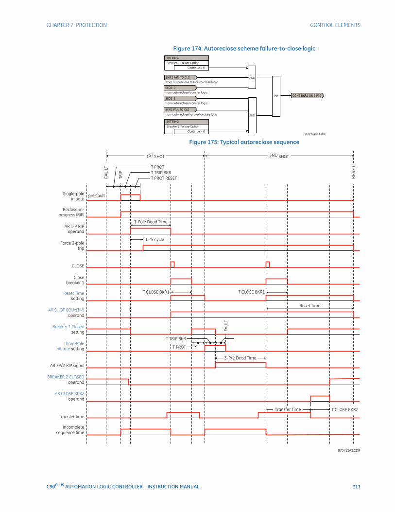
CHAPTER 7: PROTECTION CONTROL ELEMENTS
C90PLUS AUTOMATION LOGIC CONTROLLER – INSTRUCTION MANUAL 211
Figure 174: Autoreclose scheme failure-to-close logic
Figure 175: Typical autoreclose sequence
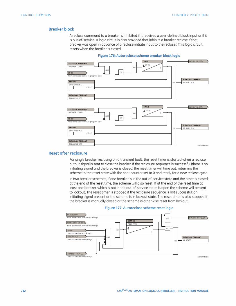
212 C90PLUS AUTOMATION LOGIC CONTROLLER – INSTRUCTION MANUAL
CONTROL ELEMENTS CHAPTER 7: PROTECTION
Breaker blockA reclose command to a breaker is inhibited if it receives a user-defined block input or if it is out-of-service. A logic circuit is also provided that inhibits a breaker reclose if that breaker was open in advance of a reclose initiate input to the recloser. This logic circuit resets when the breaker is closed.
Figure 176: Autoreclose scheme breaker block logic
Reset after reclosureFor single breaker reclosing on a transient fault, the reset timer is started when a reclose output signal is sent to close the breaker. If the reclosure sequence is successful (there is no initiating signal and the breaker is closed) the reset timer will time out, returning the scheme to the reset state with the shot counter set to 0 and ready for a new reclose cycle.
In two breaker schemes, if one breaker is in the out-of-service state and the other is closed at the end of the reset time, the scheme will also reset. If at the end of the reset time at least one breaker, which is not in the out-of-service state, is open the scheme will be sent to lockout. The reset timer is stopped if the reclosure sequence is not successful: an initiating signal present or the scheme is in lockout state. The reset timer is also stopped if the breaker is manually closed or the scheme is otherwise reset from lockout.
Figure 177: Autoreclose scheme reset logic

CHAPTER 7: PROTECTION CONTROL ELEMENTS
C90PLUS AUTOMATION LOGIC CONTROLLER – INSTRUCTION MANUAL 213
Autoreclose lockoutWhen a reclose sequence is started by an initiate signal, the autoreclose scheme moves into the reclose-in-progress state and starts the incomplete sequence timer. The setting of this timer determines the maximum time interval allowed for a single reclose shot. If a close breaker 1 or 2 signal is not present before this time expires, the scheme enters the lockout state.
There are four other conditions that can take the scheme to the lockout state.
• Receipt of the Block input while in the reclose-in-progress state.
• The reclosing program logic: when a three-phase initiate is present and the autoreclose mode is either “1 Pole” or “3 Pole-A” (three-pole autoreclose for single-pole faults only).
• Initiation of the scheme when the count is at the maximum allowed.
• If at the end of the reset time at least one breaker, which is not in the out-of-service state, is open the scheme will be sent to lockout. The scheme will be also sent to lockout if one breaker fails to reclose and the setting Breaker Failure Option setting is “Lockout”.
Once the lockout state is set, it will remain latched until one or more of the following occurs.
• The scheme is intentionally reset from lockout, employing the Reset setting of the autorecloser.
• The breaker or breakers are manually closed from the panel switch, SCADA, or other remote control through the Breaker Manual Close setting.
• Ten seconds after breaker control detects that the breaker or breakers were closed.
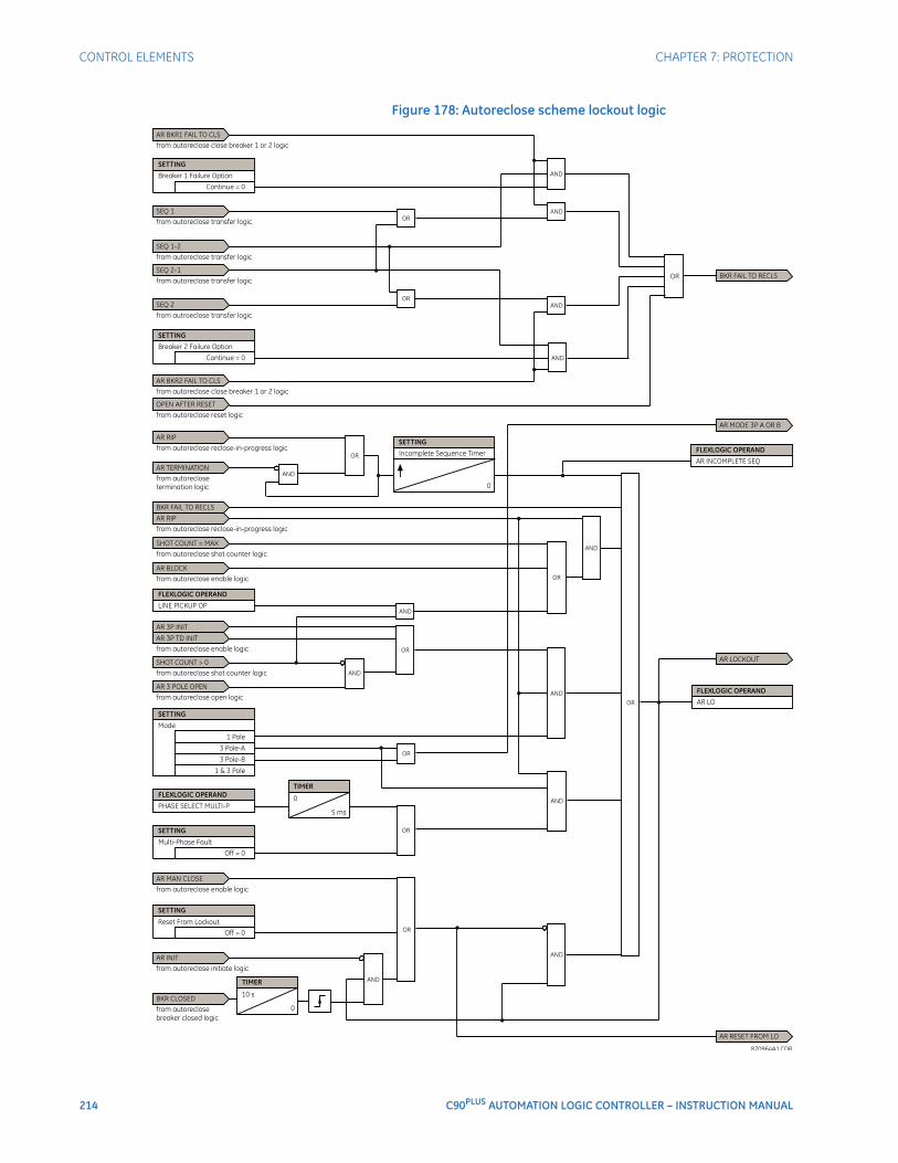
214 C90PLUS AUTOMATION LOGIC CONTROLLER – INSTRUCTION MANUAL
CONTROL ELEMENTS CHAPTER 7: PROTECTION
Figure 178: Autoreclose scheme lockout logic
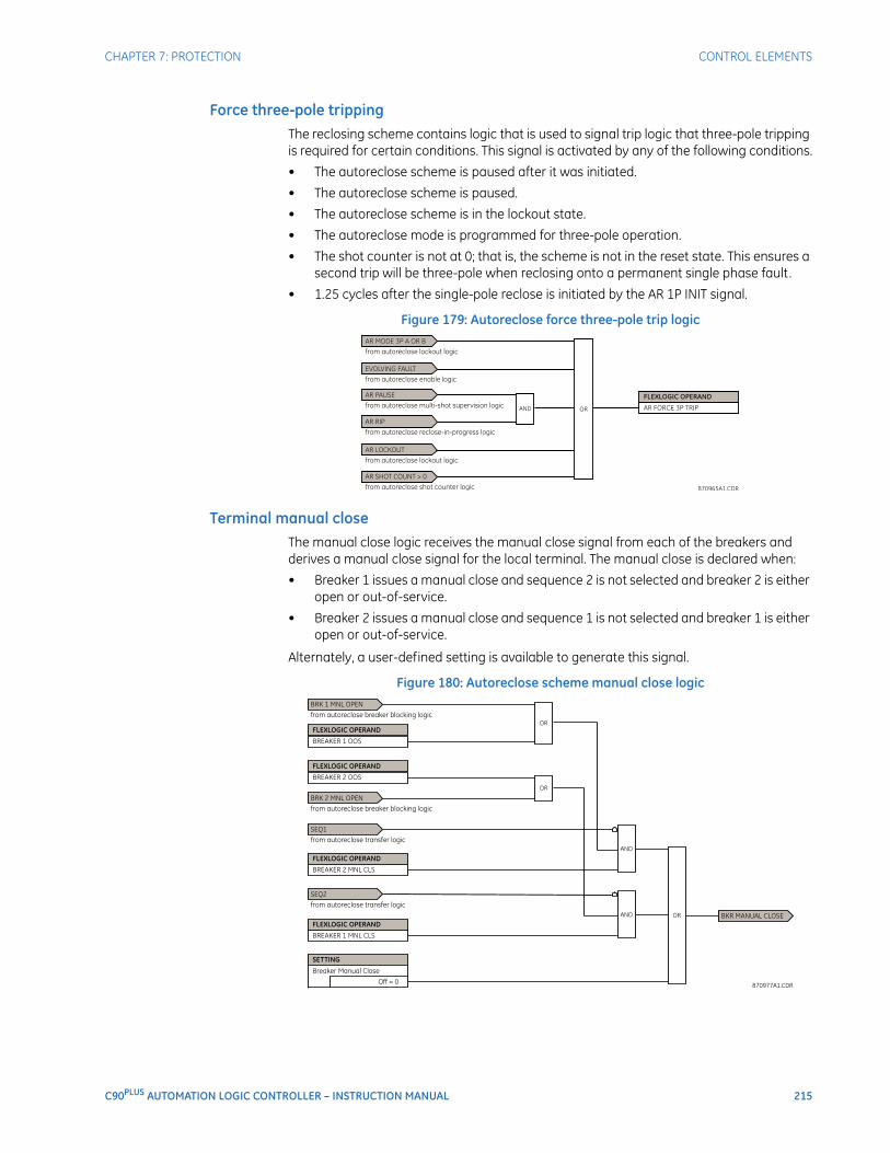
CHAPTER 7: PROTECTION CONTROL ELEMENTS
C90PLUS AUTOMATION LOGIC CONTROLLER – INSTRUCTION MANUAL 215
Force three-pole trippingThe reclosing scheme contains logic that is used to signal trip logic that three-pole tripping is required for certain conditions. This signal is activated by any of the following conditions.
• The autoreclose scheme is paused after it was initiated.
• The autoreclose scheme is paused.
• The autoreclose scheme is in the lockout state.
• The autoreclose mode is programmed for three-pole operation.
• The shot counter is not at 0; that is, the scheme is not in the reset state. This ensures a second trip will be three-pole when reclosing onto a permanent single phase fault.
• 1.25 cycles after the single-pole reclose is initiated by the AR 1P INIT signal.
Figure 179: Autoreclose force three-pole trip logic
Terminal manual closeThe manual close logic receives the manual close signal from each of the breakers and derives a manual close signal for the local terminal. The manual close is declared when:
• Breaker 1 issues a manual close and sequence 2 is not selected and breaker 2 is either open or out-of-service.
• Breaker 2 issues a manual close and sequence 1 is not selected and breaker 1 is either open or out-of-service.
Alternately, a user-defined setting is available to generate this signal.
Figure 180: Autoreclose scheme manual close logic
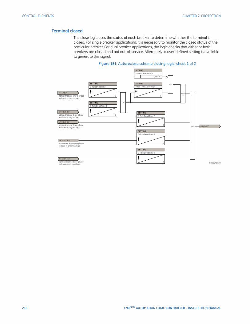
216 C90PLUS AUTOMATION LOGIC CONTROLLER – INSTRUCTION MANUAL
CONTROL ELEMENTS CHAPTER 7: PROTECTION
Terminal closedThe close logic uses the status of each breaker to determine whether the terminal is closed. For single breaker applications, it is necessary to monitor the closed status of the particular breaker. For dual breaker applications, the logic checks that either or both breakers are closed and not out-of-service. Alternately, a user-defined setting is available to generate this signal.
Figure 181: Autoreclose scheme closing logic, sheet 1 of 2
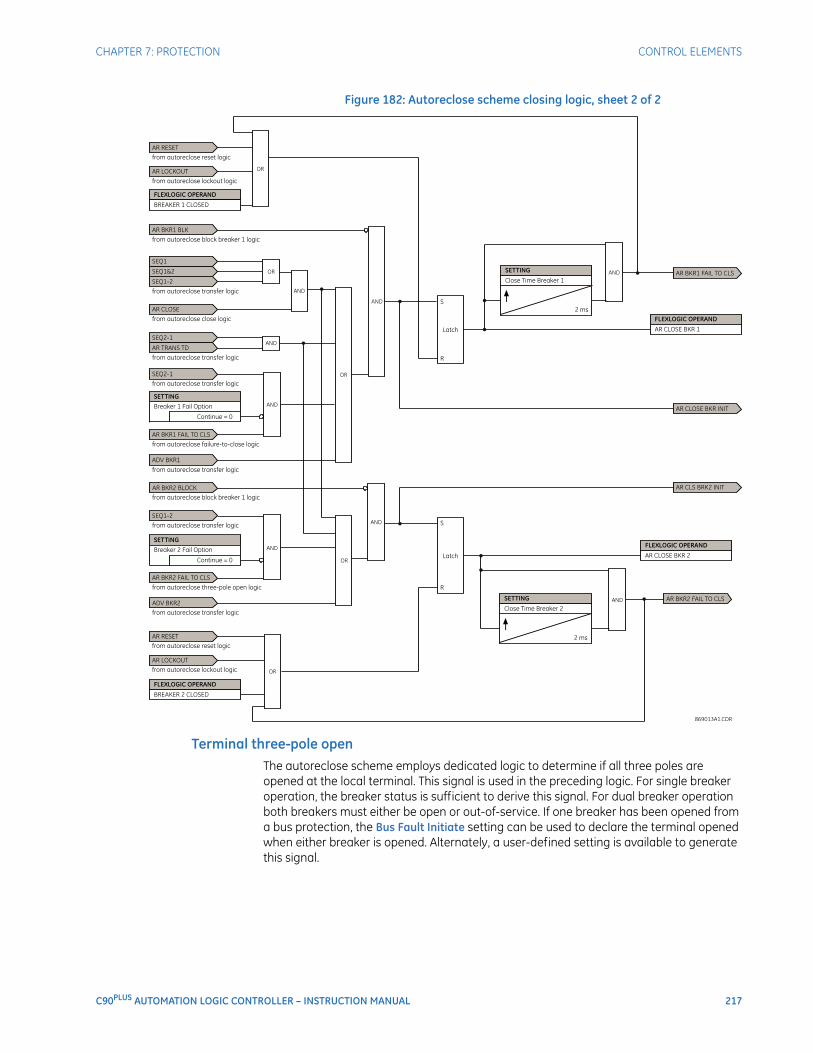
CHAPTER 7: PROTECTION CONTROL ELEMENTS
C90PLUS AUTOMATION LOGIC CONTROLLER – INSTRUCTION MANUAL 217
Figure 182: Autoreclose scheme closing logic, sheet 2 of 2
Terminal three-pole openThe autoreclose scheme employs dedicated logic to determine if all three poles are opened at the local terminal. This signal is used in the preceding logic. For single breaker operation, the breaker status is sufficient to derive this signal. For dual breaker operation both breakers must either be open or out-of-service. If one breaker has been opened from a bus protection, the Bus Fault Initiate setting can be used to declare the terminal opened when either breaker is opened. Alternately, a user-defined setting is available to generate this signal.
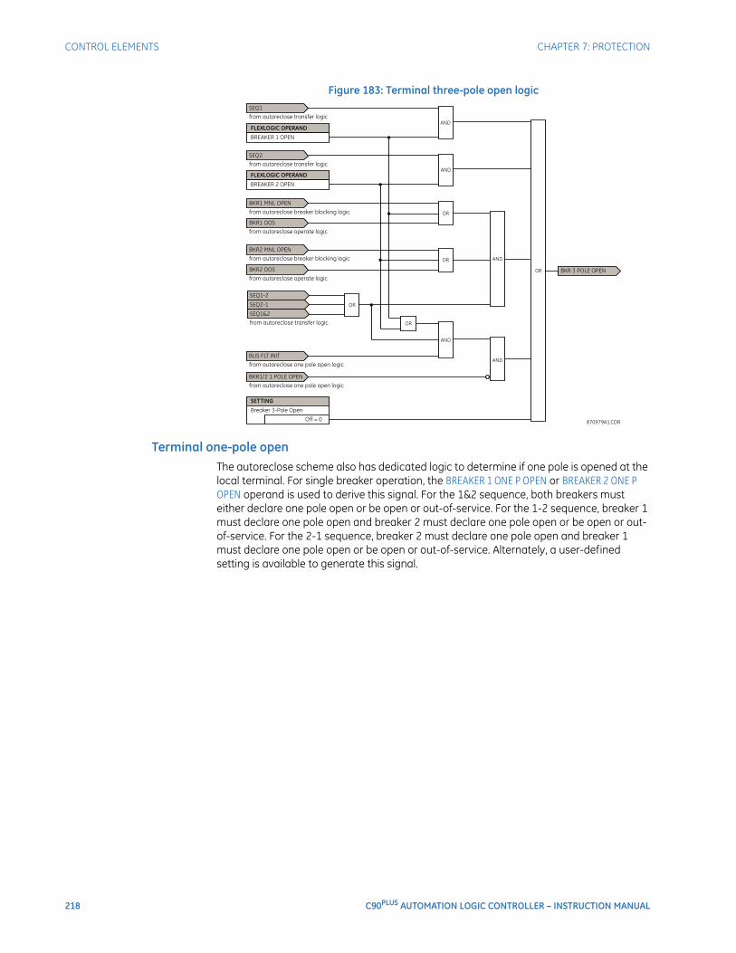
218 C90PLUS AUTOMATION LOGIC CONTROLLER – INSTRUCTION MANUAL
CONTROL ELEMENTS CHAPTER 7: PROTECTION
Figure 183: Terminal three-pole open logic
Terminal one-pole openThe autoreclose scheme also has dedicated logic to determine if one pole is opened at the local terminal. For single breaker operation, the BREAKER 1 ONE P OPEN or BREAKER 2 ONE P OPEN operand is used to derive this signal. For the 1&2 sequence, both breakers must either declare one pole open or be open or out-of-service. For the 1-2 sequence, breaker 1 must declare one pole open and breaker 2 must declare one pole open or be open or out-of-service. For the 2-1 sequence, breaker 2 must declare one pole open and breaker 1 must declare one pole open or be open or out-of-service. Alternately, a user-defined setting is available to generate this signal.
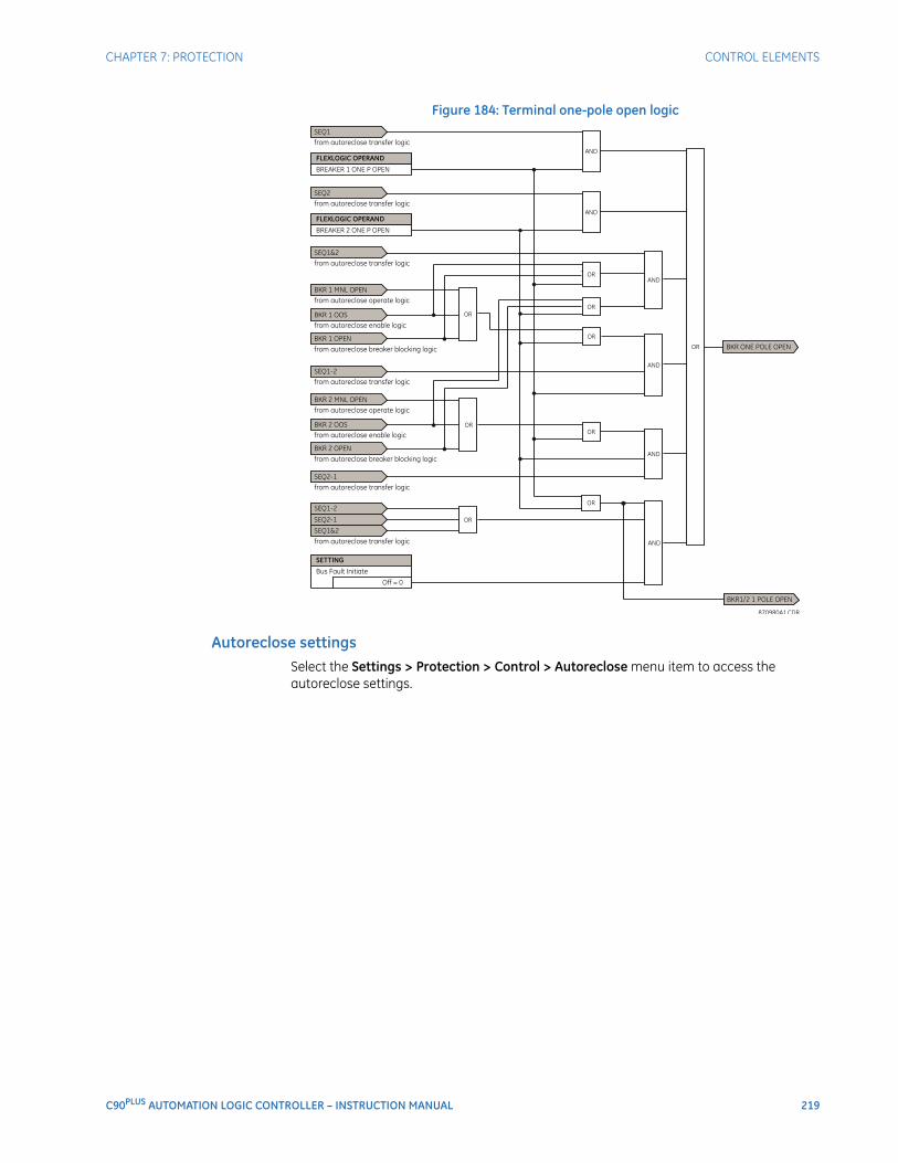
CHAPTER 7: PROTECTION CONTROL ELEMENTS
C90PLUS AUTOMATION LOGIC CONTROLLER – INSTRUCTION MANUAL 219
Figure 184: Terminal one-pole open logic
Autoreclose settingsSelect the Settings > Protection > Control > Autoreclose menu item to access the autoreclose settings.
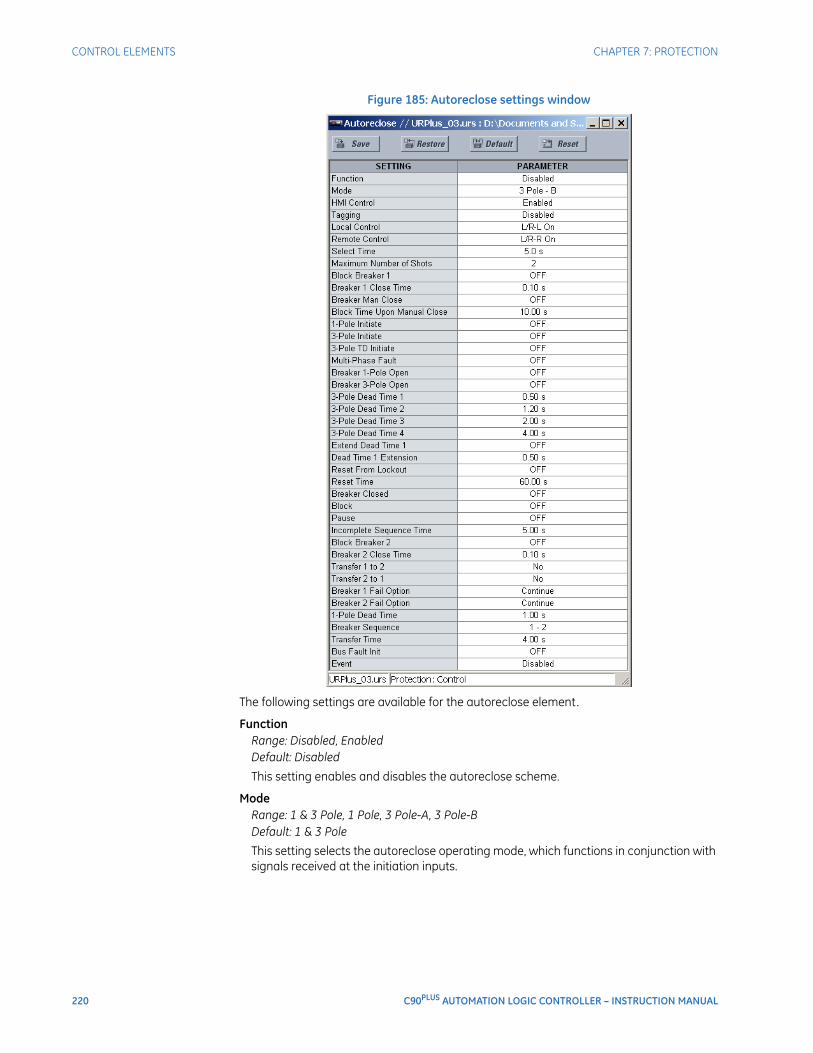
220 C90PLUS AUTOMATION LOGIC CONTROLLER – INSTRUCTION MANUAL
CONTROL ELEMENTS CHAPTER 7: PROTECTION
Figure 185: Autoreclose settings window
The following settings are available for the autoreclose element.
FunctionRange: Disabled, EnabledDefault: Disabled
This setting enables and disables the autoreclose scheme.
ModeRange: 1 & 3 Pole, 1 Pole, 3 Pole-A, 3 Pole-BDefault: 1 & 3 Pole
This setting selects the autoreclose operating mode, which functions in conjunction with signals received at the initiation inputs.

CHAPTER 7: PROTECTION CONTROL ELEMENTS
C90PLUS AUTOMATION LOGIC CONTROLLER – INSTRUCTION MANUAL 221
Select TimeRange: 1.0 to 30.0 seconds in steps of 0.1Default: 5 seconds
This setting determines the maximum permissible time from selection of autoreclose and a control action.
Maximum Number of ShotsRange: 1, 2, 3, 4Default: 2
This setting specifies the number of reclosures attempted before reclosure goes to lockout when the fault is permanent.
Block Breaker 1Range: any FlexLogic™ operand or shared operandDefault: Off
This setting selects an operand that will block the reclose command for breaker 1. This condition can include breaker low air pressure, reclose in progress on another line (for the central breaker in a breaker and a half arrangement), or a sum of conditions combined in FlexLogic™.
Close Time Breaker 1Range: 0.00 to 655.35 seconds in steps of 0.01Default: 0.10 seconds
This setting represents the closing time for breaker 1 from the moment the CLOSE command is sent to the moment the contacts are closed.
Breaker Manual CloseRange: any FlexLogic™ operand or shared operandDefault: Off
This setting selects an operand that represents a manual close command to a breaker associated with the autoreclose scheme.
Block Time Upon Manual CloseRange: 0.00 to 655.35 seconds in steps of 0.01Default: 10.00 seconds
The autoreclose scheme can be disabled for a programmable time delay after an associated circuit breaker is manually commanded to close, preventing reclosing onto an existing fault such as grounds on the line. This delay must be longer than the slowest expected trip from any protection not blocked after manual closing. If the autoreclose scheme is not initiated after a manual close and this time expires, the autoreclose scheme is set to the reset state.
1-Pole InitiateRange: any FlexLogic™ operand or shared operandDefault: Off
This setting selects an operand used to initiate single-pole autoreclosure.
3-Pole InitiateRange: any FlexLogic™ operand or shared operandDefault: Off
This setting selects an operand used to initiate three-pole autoreclosure. The first timer (3-Pole Dead Time 1) can be used for a high-speed autoreclosure.

222 C90PLUS AUTOMATION LOGIC CONTROLLER – INSTRUCTION MANUAL
CONTROL ELEMENTS CHAPTER 7: PROTECTION
3-Pole TD InitiateRange: any FlexLogic™ operand or shared operandDefault: Off
This setting selects an operand used to initiate three-pole autoreclosure. The second timer (3-Pole Dead Time 2) can be used for a time-delay autoreclosure.
Multi-Phase FaultRange: any FlexLogic™ operand or shared operandDefault: Off
This setting selects an operand used to indicate a multi-phase fault. The operand value should be zero for single-phase to ground faults.
Breaker 1-Pole OpenRange: any FlexLogic™ operand or shared operandDefault: Off
This setting selects an operand to indicate that the breaker or breakers have opened correctly following a single-phase to ground fault. The autoreclose scheme can then start timing the single-pole dead time. For example, if the reclose sequence is “1-2”, breaker 1 should trip single-pole and breaker 2 should trip three-pole).
The scheme has a pre-wired input that indicates breaker status.
Breaker 3-Pole OpenRange: any FlexLogic™ operand or shared operandDefault: Off
This setting selects an operand to indicate that the breaker or breakers have opened three-pole and the autoreclose scheme can start timing the three-pole dead time. The scheme has a pre-wired input that indicates breaker status.
3-Pole Dead Time 1Range: 0.00 to 655.35 seconds in steps of 0.01Default: 0.50 seconds
This setting represents the dead time following the first three-pole trip. This intentional delay can be used for a high-speed three-pole autoreclose. However, it should be set longer than the estimated de-ionizing time following the three-pole trip.
3-Pole Dead Time 2Range: 0.00 to 655.35 seconds in steps of 0.01Default: 1.20 seconds
This is the dead time following the second three-pole trip or initiated by the 3-Pole Time Delay Initiate setting. This intentional delay is typically used for a time delayed three-pole autoreclose (as opposed to high speed three-pole autoreclose).
3 Pole Dead Time 3Range: 0.00 to 655.35 seconds in steps of 0.01Default: 2.00 seconds
This setting represents the dead time following the third three-pole trip.
3-Pole Dead Time 4Range: 0.00 to 655.35 seconds in steps of 0.01Default: 4.00 seconds
This setting represents the dead time following the fourth three-pole trip.

CHAPTER 7: PROTECTION CONTROL ELEMENTS
C90PLUS AUTOMATION LOGIC CONTROLLER – INSTRUCTION MANUAL 223
Extend Dead Time 1Range: any FlexLogic™ operand or shared operandDefault: Off
This setting selects an operand that will adapt the duration of the dead time for the first shot to the possibility of non-simultaneous tripping at the two line ends. Typically this is the operand set when the communication channel is out-of-service.
Dead Time 1 ExtensionRange: 0.00 to 655.35 seconds in steps of 0.01Default: 0.50 seconds
This timer is used to set the length of the dead time 1 extension for possible non-simultaneous tripping of the two ends of the line.
ResetRange: any FlexLogic™ operand or shared operandDefault: Off
This setting selects the operand that forces the autoreclose scheme from any state to reset. Typically this is a manual reset from lockout, local or remote.
Reset TimeRange: 0.00 to 655.35 seconds in steps of 0.01Default: 60.00 seconds
A reset timer output resets the recloser following a successful reclosure sequence. The setting is based on the breaker time, which is the minimum time required between successive reclose sequences.
Breaker ClosedRange: any FlexLogic™ operand or shared operandDefault: Off
This setting selects an operand that indicates that the breaker(s) are closed at the end of the reset time and the scheme can reset.
BlockRange: any FlexLogic™ operand or shared operandDefault: Off
This setting selects the operand that blocks the autoreclose scheme (it can be a sum of conditions such as time delayed tripping, breaker failure, and differential protection). If the block signal is present before autoreclose scheme initiation the AR DISABLED FlexLogic™ operand will be set. If the block signal occurs when the scheme is in the reclose-in-progress state the scheme will be sent to lockout.
PauseRange: any FlexLogic™ operand or shared operandDefault: Off
This setting offers the ability to freeze the autoreclose cycle until the pause signal disappears. This may be done when a trip occurs and simultaneously or previously, some conditions are detected such as out-of step or loss of guard frequency, or a remote transfer trip signal is received. The autoreclose cycle is resumed when the pause signal disappears. This feature can also be used when a transformer is tapped from the protected line and a reclose is not desirable until the it is disconnected from the line. In this situation, the reclose scheme is ‘paused’ until the transformer is disconnected.
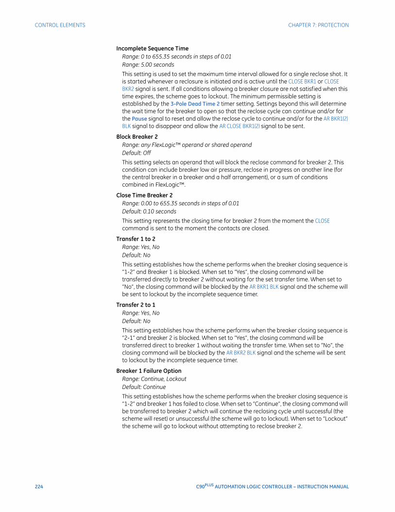
224 C90PLUS AUTOMATION LOGIC CONTROLLER – INSTRUCTION MANUAL
CONTROL ELEMENTS CHAPTER 7: PROTECTION
Incomplete Sequence TimeRange: 0 to 655.35 seconds in steps of 0.01Range: 5.00 seconds
This setting is used to set the maximum time interval allowed for a single reclose shot. It is started whenever a reclosure is initiated and is active until the CLOSE BKR1 or CLOSE BKR2 signal is sent. If all conditions allowing a breaker closure are not satisfied when this time expires, the scheme goes to lockout. The minimum permissible setting is established by the 3-Pole Dead Time 2 timer setting. Settings beyond this will determine the wait time for the breaker to open so that the reclose cycle can continue and/or for the Pause signal to reset and allow the reclose cycle to continue and/or for the AR BKR1(2) BLK signal to disappear and allow the AR CLOSE BKR1(2) signal to be sent.
Block Breaker 2Range: any FlexLogic™ operand or shared operandDefault: Off
This setting selects an operand that will block the reclose command for breaker 2. This condition can include breaker low air pressure, reclose in progress on another line (for the central breaker in a breaker and a half arrangement), or a sum of conditions combined in FlexLogic™.
Close Time Breaker 2Range: 0.00 to 655.35 seconds in steps of 0.01Default: 0.10 seconds
This setting represents the closing time for breaker 2 from the moment the CLOSE command is sent to the moment the contacts are closed.
Transfer 1 to 2Range: Yes, NoDefault: No
This setting establishes how the scheme performs when the breaker closing sequence is “1-2” and Breaker 1 is blocked. When set to “Yes”, the closing command will be transferred directly to breaker 2 without waiting for the set transfer time. When set to “No”, the closing command will be blocked by the AR BKR1 BLK signal and the scheme will be sent to lockout by the incomplete sequence timer.
Transfer 2 to 1Range: Yes, NoDefault: No
This setting establishes how the scheme performs when the breaker closing sequence is “2-1” and breaker 2 is blocked. When set to “Yes”, the closing command will be transferred direct to breaker 1 without waiting the transfer time. When set to “No”, the closing command will be blocked by the AR BKR2 BLK signal and the scheme will be sent to lockout by the incomplete sequence timer.
Breaker 1 Failure OptionRange: Continue, LockoutDefault: Continue
This setting establishes how the scheme performs when the breaker closing sequence is “1-2” and breaker 1 has failed to close. When set to “Continue”, the closing command will be transferred to breaker 2 which will continue the reclosing cycle until successful (the scheme will reset) or unsuccessful (the scheme will go to lockout). When set to “Lockout” the scheme will go to lockout without attempting to reclose breaker 2.

CHAPTER 7: PROTECTION CONTROL ELEMENTS
C90PLUS AUTOMATION LOGIC CONTROLLER – INSTRUCTION MANUAL 225
Breaker 2 Failure OptionRange: Continue, LockoutDefault: Continue
This setting establishes how the scheme performs when the breaker closing sequence is “2-1” and breaker 2 has failed to close. When set to “Continue”, the closing command will be transferred to breaker 1 which will continue the reclosing cycle until successful (the scheme will reset) or unsuccessful (the scheme will go to lockout). When set to “Lockout”, the scheme will go to lockout without attempting to reclose breaker 1.
1-Pole Dead TimeRange: 0 to 655.35 seconds in steps of 0.01Default: 1.00 seconds
Set this intentional delay longer than the estimated de-ionizing time after the first single-pole trip.
Breaker SequenceRange: 1, 2, 1&2, 1-2, 2-1Default: 1-2
This setting selects the breaker reclose sequence. Select “1” to reclose breaker 1 only, “2” for reclose breaker 2 only, “1&2” to reclose both breakers simultaneously, “1-2” to reclose breakers sequentially with breaker 1 first, and “2-1” to reclose breakers sequentially with breaker 2 first.
Bus Fault InitiateRange: any FlexLogic™ operand or shared operandDefault: OFF
This setting is used in breaker-and-a-half applications to allow the autoreclose control function to perform reclosing with only one breaker previously opened by bus protection. For line faults, both breakers must open for the autoreclose reclosing cycles to take effect.
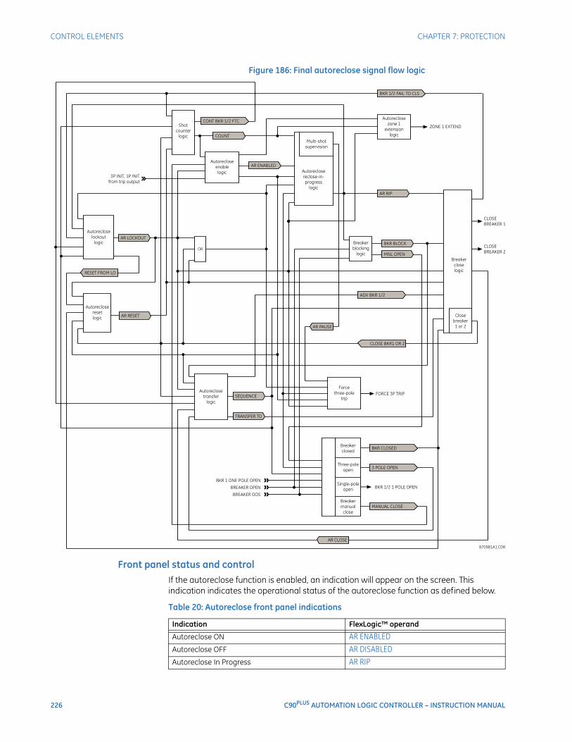
226 C90PLUS AUTOMATION LOGIC CONTROLLER – INSTRUCTION MANUAL
CONTROL ELEMENTS CHAPTER 7: PROTECTION
Figure 186: Final autoreclose signal flow logic
Front panel status and controlIf the autoreclose function is enabled, an indication will appear on the screen. This indication indicates the operational status of the autoreclose function as defined below.
Table 20: Autoreclose front panel indications
Indication FlexLogic™ operand
Autoreclose ON AR ENABLEDAutoreclose OFF AR DISABLEDAutoreclose In Progress AR RIP
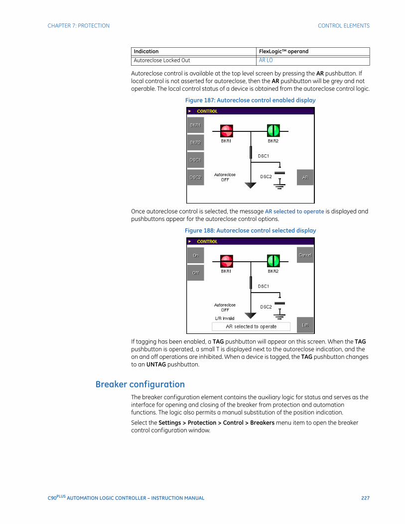
CHAPTER 7: PROTECTION CONTROL ELEMENTS
C90PLUS AUTOMATION LOGIC CONTROLLER – INSTRUCTION MANUAL 227
Autoreclose control is available at the top level screen by pressing the AR pushbutton. If local control is not asserted for autoreclose, then the AR pushbutton will be grey and not operable. The local control status of a device is obtained from the autoreclose control logic.
Figure 187: Autoreclose control enabled display
Once autoreclose control is selected, the message AR selected to operate is displayed and pushbuttons appear for the autoreclose control options.
Figure 188: Autoreclose control selected display
If tagging has been enabled, a TAG pushbutton will appear on this screen. When the TAG pushbutton is operated, a small T is displayed next to the autoreclose indication, and the on and off operations are inhibited. When a device is tagged, the TAG pushbutton changes to an UNTAG pushbutton.
Breaker configurationThe breaker configuration element contains the auxiliary logic for status and serves as the interface for opening and closing of the breaker from protection and automation functions. The logic also permits a manual substitution of the position indication.
Select the Settings > Protection > Control > Breakers menu item to open the breaker control configuration window.
Autoreclose Locked Out AR LOIndication FlexLogic™ operand
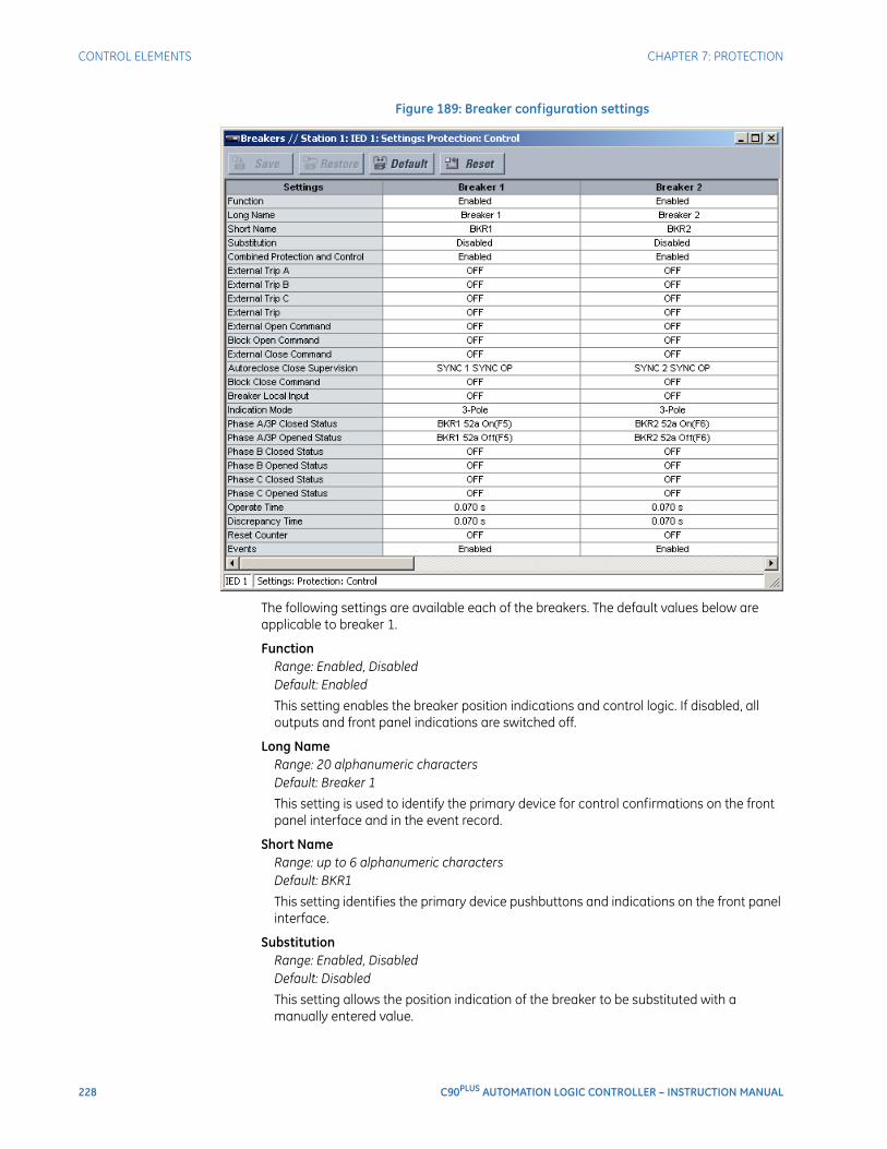
228 C90PLUS AUTOMATION LOGIC CONTROLLER – INSTRUCTION MANUAL
CONTROL ELEMENTS CHAPTER 7: PROTECTION
Figure 189: Breaker configuration settings
The following settings are available each of the breakers. The default values below are applicable to breaker 1.
FunctionRange: Enabled, DisabledDefault: Enabled
This setting enables the breaker position indications and control logic. If disabled, all outputs and front panel indications are switched off.
Long NameRange: 20 alphanumeric charactersDefault: Breaker 1
This setting is used to identify the primary device for control confirmations on the front panel interface and in the event record.
Short NameRange: up to 6 alphanumeric charactersDefault: BKR1
This setting identifies the primary device pushbuttons and indications on the front panel interface.
SubstitutionRange: Enabled, DisabledDefault: Disabled
This setting allows the position indication of the breaker to be substituted with a manually entered value.

CHAPTER 7: PROTECTION CONTROL ELEMENTS
C90PLUS AUTOMATION LOGIC CONTROLLER – INSTRUCTION MANUAL 229
Combined Protection and ControlRange: Enabled, DisabledDefault: Enabled
If this setting is enabled, the tripping signals from the trip output scheme are logically ORed with the open signal from the breaker control scheme.
External Trip A, External Trip B, External Trip CRange: any FlexLogic™ operand or shared operandDefault: Off
These settings assign an operand (usually an external contact input) to the breaker trip pole A, B, and C reporting contact.
External Open CommandRange: any FlexLogic™ operand or shared operandDefault: Off
This setting assigns an operand that creates a programmable signal to operate an output relay to open the breaker.
Block Open CommandRange: any FlexLogic™ operand or shared operandDefault: Off
This setting selects an operand that prevents opening of the breaker. This setting can be used for select-before-operate functionality or to block operation from a panel switch or from SCADA.
External Close CommandRange: any FlexLogic™ operand or shared operandDefault: Off
This setting assigns an operand that creates a programmable signal to operate an output relay to close the breaker.
Autoreclose Close SupervisionRange: any FlexLogic™ operand or shared operandDefault: SYNC 1 SYNC OP
This setting selects an operand to supervise the closing of the breaker from autoreclose. If no supervision is required, this setting should be programmed as “On”.
Block Close CommandRange: any FlexLogic™ operand or shared operandDefault: Off
This setting selects an operand that prevents closing of the breaker. This setting can be used for select-before-operate functionality or to block operation from a panel switch or from SCADA.
Breaker Local InputRange: any FlexLogic™ operand or shared operandDefault: OFF
Closing or opening of the breaker through the breaker interlock element is inhibited if the operand assigned to this setting is asserted.
Indication ModeRange: 3 Pole, 1 PoleDefault: 3 Pole
If “3 Pole” is selected, the breaker indications are derived from a single status input (or pair of status inputs). If “1 Pole” is selected, the breaker indications are derived from three status inputs (or pairs of status inputs).
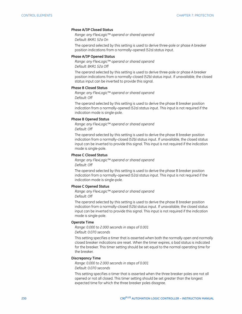
230 C90PLUS AUTOMATION LOGIC CONTROLLER – INSTRUCTION MANUAL
CONTROL ELEMENTS CHAPTER 7: PROTECTION
Phase A/3P Closed StatusRange: any FlexLogic™ operand or shared operandDefault: BKR1 52a On
The operand selected by this setting is used to derive three-pole or phase A breaker position indications from a normally-opened (52a) status input.
Phase A/3P Opened StatusRange: any FlexLogic™ operand or shared operandDefault: BKR1 52a Off
The operand selected by this setting is used to derive three-pole or phase A breaker position indications from a normally-closed (52b) status input. If unavailable, the closed status input can be inverted to provide this signal.
Phase B Closed StatusRange: any FlexLogic™ operand or shared operandDefault: Off
The operand selected by this setting is used to derive the phase B breaker position indication from a normally-opened (52a) status input. This input is not required if the indication mode is single-pole.
Phase B Opened StatusRange: any FlexLogic™ operand or shared operandDefault: Off
The operand selected by this setting is used to derive the phase B breaker position indication from a normally-closed (52b) status input. If unavailable, the closed status input can be inverted to provide this signal. This input is not required if the indication mode is single-pole.
Phase C Closed StatusRange: any FlexLogic™ operand or shared operandDefault: Off
The operand selected by this setting is used to derive the phase B breaker position indication from a normally-opened (52a) status input. This input is not required if the indication mode is single-pole.
Phase C Opened StatusRange: any FlexLogic™ operand or shared operandDefault: Off
The operand selected by this setting is used to derive the phase B breaker position indication from a normally-closed (52b) status input. If unavailable, the closed status input can be inverted to provide this signal. This input is not required if the indication mode is single-pole.
Operate TimeRange: 0.000 to 2.000 seconds in steps of 0.001Default: 0.070 seconds
This setting specifies a timer that is asserted when both the normally open and normally closed breaker indications are reset. When the timer expires, a bad status is indicated for the breaker. This timer setting should be set equal to the normal operating time for the breaker.
Discrepancy TimeRange: 0.000 to 2.000 seconds in steps of 0.001Default: 0.070 seconds
This setting specifies a timer that is asserted when the three breaker poles are not all opened or not all closed. This timer setting should be set greater than the longest expected time for which the three breaker poles disagree.

CHAPTER 7: PROTECTION CONTROL ELEMENTS
C90PLUS AUTOMATION LOGIC CONTROLLER – INSTRUCTION MANUAL 231
Reset CounterRange: any FlexLogic™ operand or shared operandDefault: Off
Assertion of the operand assigned to this setting resets the breaker operation counters.
EventsRange: Enabled, DisabledDefault: Enabled
This settings enables the recording of breaker configuration events in the sequence of events record.
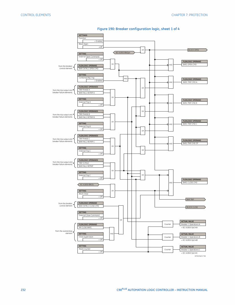
232 C90PLUS AUTOMATION LOGIC CONTROLLER – INSTRUCTION MANUAL
CONTROL ELEMENTS CHAPTER 7: PROTECTION
Figure 190: Breaker configuration logic, sheet 1 of 4
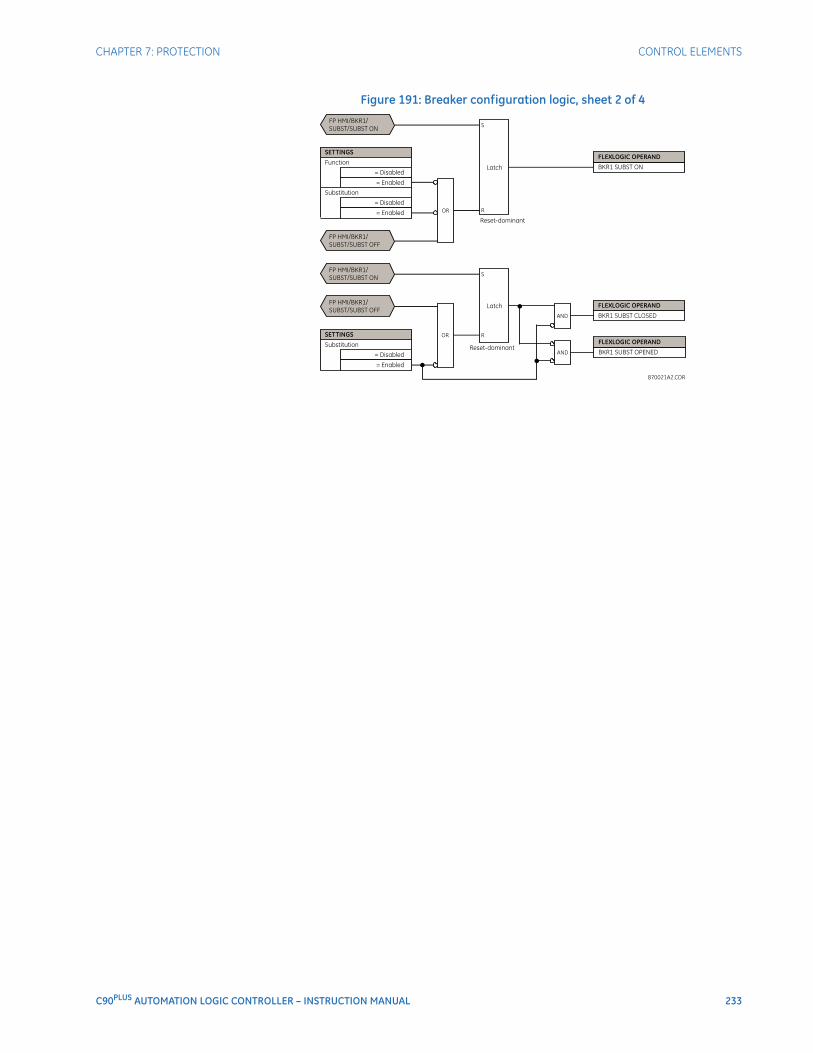
CHAPTER 7: PROTECTION CONTROL ELEMENTS
C90PLUS AUTOMATION LOGIC CONTROLLER – INSTRUCTION MANUAL 233
Figure 191: Breaker configuration logic, sheet 2 of 4
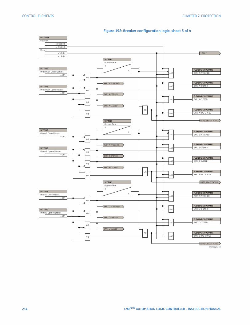
234 C90PLUS AUTOMATION LOGIC CONTROLLER – INSTRUCTION MANUAL
CONTROL ELEMENTS CHAPTER 7: PROTECTION
Figure 192: Breaker configuration logic, sheet 3 of 4
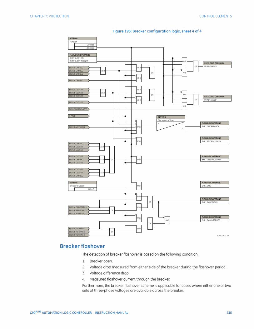
CHAPTER 7: PROTECTION CONTROL ELEMENTS
C90PLUS AUTOMATION LOGIC CONTROLLER – INSTRUCTION MANUAL 235
Figure 193: Breaker configuration logic, sheet 4 of 4
Breaker flashoverThe detection of breaker flashover is based on the following condition.
1. Breaker open.
2. Voltage drop measured from either side of the breaker during the flashover period.
3. Voltage difference drop.
4. Measured flashover current through the breaker.
Furthermore, the breaker flashover scheme is applicable for cases where either one or two sets of three-phase voltages are available across the breaker.
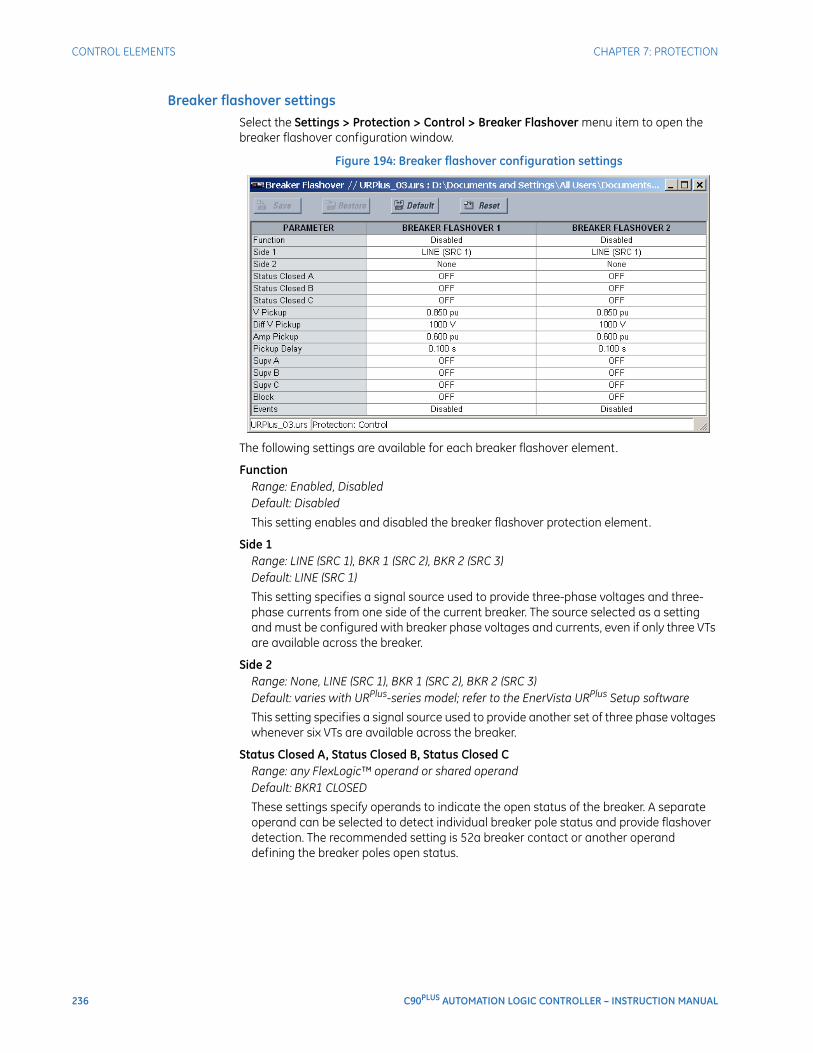
236 C90PLUS AUTOMATION LOGIC CONTROLLER – INSTRUCTION MANUAL
CONTROL ELEMENTS CHAPTER 7: PROTECTION
Breaker flashover settingsSelect the Settings > Protection > Control > Breaker Flashover menu item to open the breaker flashover configuration window.
Figure 194: Breaker flashover configuration settings
The following settings are available for each breaker flashover element.
FunctionRange: Enabled, DisabledDefault: Disabled
This setting enables and disabled the breaker flashover protection element.
Side 1Range: LINE (SRC 1), BKR 1 (SRC 2), BKR 2 (SRC 3)Default: LINE (SRC 1)
This setting specifies a signal source used to provide three-phase voltages and three-phase currents from one side of the current breaker. The source selected as a setting and must be configured with breaker phase voltages and currents, even if only three VTs are available across the breaker.
Side 2Range: None, LINE (SRC 1), BKR 1 (SRC 2), BKR 2 (SRC 3)Default: varies with URPlus-series model; refer to the EnerVista URPlus Setup software
This setting specifies a signal source used to provide another set of three phase voltages whenever six VTs are available across the breaker.
Status Closed A, Status Closed B, Status Closed CRange: any FlexLogic™ operand or shared operandDefault: BKR1 CLOSED
These settings specify operands to indicate the open status of the breaker. A separate operand can be selected to detect individual breaker pole status and provide flashover detection. The recommended setting is 52a breaker contact or another operand defining the breaker poles open status.

CHAPTER 7: PROTECTION CONTROL ELEMENTS
C90PLUS AUTOMATION LOGIC CONTROLLER – INSTRUCTION MANUAL 237
Voltage PickupRange: 0.000 to 1.500 pu in steps of 0.001Default: 0.850 pu
This setting specifies a pickup level for the phase voltages from both sides of the breaker. If six VTs are available, opening the breaker leads to two possible combinations – live voltages from only one side of the breaker, or live voltages from both sides of the breaker. Either case will set the scheme ready for flashover detection upon detection of voltage above the selected value. Set this value to 85 to 90% of the nominal voltage.
Voltage Difference PickupRange: 0 to 100000 volts in steps of 1Default: 1000 volts
This setting specifies a pickup level for the phase voltage difference when two VTs per phase are available across the breaker. The pickup voltage difference should be below the monitored voltage difference when close or open breaker resistors are left in service. The setting is selected as primary volts difference between the sources.
Current PickupRange: 0.000 to 1.500 pu in steps of 0.001Default: 0.600 pu
This setting specifies the normal load current which can flow through the breaker. Depending on the flashover protection application, the flashover current can vary from levels of the charging current when the line is de-energized (all line breakers open), to well above the maximum line (feeder) load (line/feeder connected to load).
Pickup DelayRange: 0.000 to 65.535 seconds in steps of 0.001Default: 0.100 seconds
This setting specifies the time delay to operate the breaker flashover element after a pickup condition is detected.
Supervision A, Supervision B, Supervision CRange: any FlexLogic™ operand or shared operandDefault: OFF
These settings specify operands (per breaker pole) that supervise the operation of the element per phase. Supervision can be provided by operation of other protection elements, breaker failure, and close and trip commands. A six-cycle time delay applies after the selected operand resets.
BlockRange: any FlexLogic™ operand or shared operandDefault: OFF
Assertion of the operand assigned to this setting blocks operation of the breaker flashover element.
EventsRange: Enabled, DisabledDefault: varies with URPlus-series model; refer to the EnerVista URPlus Setup software
This setting enables and disables the logging of breaker flashover events in the sequence of events recorder.
The logic for the breaker flashover element is shown below.
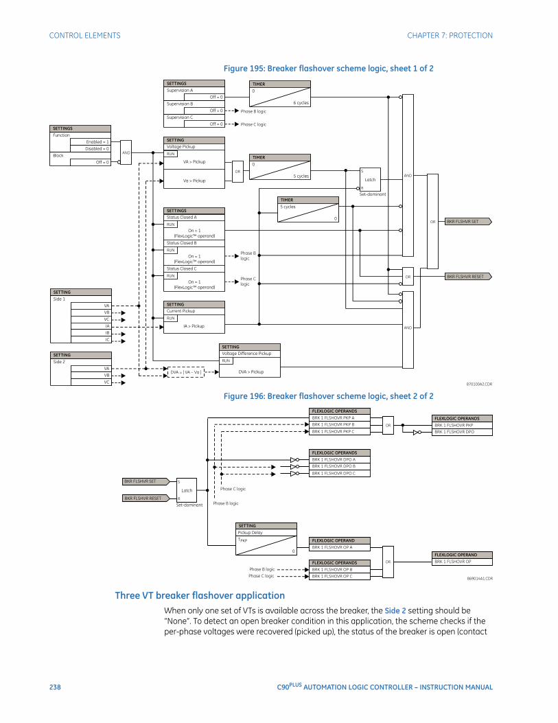
238 C90PLUS AUTOMATION LOGIC CONTROLLER – INSTRUCTION MANUAL
CONTROL ELEMENTS CHAPTER 7: PROTECTION
Figure 195: Breaker flashover scheme logic, sheet 1 of 2
Figure 196: Breaker flashover scheme logic, sheet 2 of 2
Three VT breaker flashover applicationWhen only one set of VTs is available across the breaker, the Side 2 setting should be “None”. To detect an open breaker condition in this application, the scheme checks if the per-phase voltages were recovered (picked up), the status of the breaker is open (contact
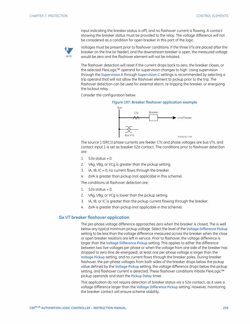
CHAPTER 7: PROTECTION CONTROL ELEMENTS
C90PLUS AUTOMATION LOGIC CONTROLLER – INSTRUCTION MANUAL 239
input indicating the breaker status is off), and no flashover current is flowing. A contact showing the breaker status must be provided to the relay. The voltage difference will not be considered as a condition for open breaker in this part of the logic.
NOTE
NOTE: Voltages must be present prior to flashover conditions. If the three VTs are placed after the breaker on the line (or feeder), and the downstream breaker is open, the measured voltage would be zero and the flashover element will not be initiated.
The flashover detection will reset if the current drops back to zero, the breaker closes, or the selected FlexLogic™ operand for supervision changes to high. Using supervision through the Supervision A through Supervision C settings is recommended by selecting a trip operand that will not allow the flashover element to pickup prior to the trip. The flashover detection can be used for external alarm, re-tripping the breaker, or energizing the lockout relay.
Consider the configuration below.
Figure 197: Breaker flashover application example
The source 1 (SRC1) phase currents are feeder CTs and phase voltages are bus VTs, and contact input 1 is set as breaker 52a contact. The conditions prior to flashover detection are:
1. 52a status = 0.
2. VAg, VBg, or VCg is greater than the pickup setting.
3. IA, IB, IC = 0; no current flows through the breaker.
4. ∆VA is greater than pickup (not applicable in this scheme).
The conditions at flashover detection are:
1. 52a status = 0.
2. VAg, VBg, or VCg is lower than the pickup setting.
3. IA, IB, or IC is greater than the pickup current flowing through the breaker.
4. ∆VA is greater than pickup (not applicable in this scheme).
Six VT breaker flashover applicationThe per-phase voltage difference approaches zero when the breaker is closed. The is well below any typical minimum pickup voltage. Select the level of the Voltage Difference Pickup setting to be less than the voltage difference measured across the breaker when the close or open breaker resistors are left in service. Prior to flashover, the voltage difference is larger than the Voltage Difference Pickup setting. This applies to either the difference between two live voltages per phase or when the voltage from one side of the breaker has dropped to zero (line de-energized), at least one per-phase voltage is larger than the Voltage Pickup setting, and no current flows through the breaker poles. During breaker flashover, the per-phase voltages from both sides of the breaker drops below the pickup value defined by the Voltage Pickup setting, the voltage difference drops below the pickup setting, and flashover current is detected. These flashover conditions initiate FlexLogic™ pickup operands and start the Pickup Delay timer.
This application do not require detection of breaker status via a 52a contact, as it uses a voltage difference larger than the Voltage Difference Pickup setting. However, monitoring the breaker contact will ensure scheme stability.
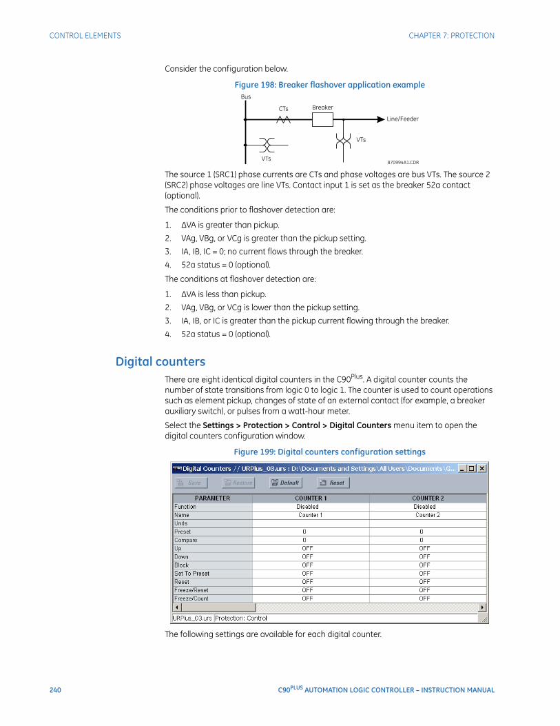
240 C90PLUS AUTOMATION LOGIC CONTROLLER – INSTRUCTION MANUAL
CONTROL ELEMENTS CHAPTER 7: PROTECTION
Consider the configuration below.
Figure 198: Breaker flashover application example
The source 1 (SRC1) phase currents are CTs and phase voltages are bus VTs. The source 2 (SRC2) phase voltages are line VTs. Contact input 1 is set as the breaker 52a contact (optional).
The conditions prior to flashover detection are:
1. ∆VA is greater than pickup.
2. VAg, VBg, or VCg is greater than the pickup setting.
3. IA, IB, IC = 0; no current flows through the breaker.
4. 52a status = 0 (optional).
The conditions at flashover detection are:
1. ∆VA is less than pickup.
2. VAg, VBg, or VCg is lower than the pickup setting.
3. IA, IB, or IC is greater than the pickup current flowing through the breaker.
4. 52a status = 0 (optional).
Digital countersThere are eight identical digital counters in the C90Plus. A digital counter counts the number of state transitions from logic 0 to logic 1. The counter is used to count operations such as element pickup, changes of state of an external contact (for example, a breaker auxiliary switch), or pulses from a watt-hour meter.
Select the Settings > Protection > Control > Digital Counters menu item to open the digital counters configuration window.
Figure 199: Digital counters configuration settings
The following settings are available for each digital counter.

CHAPTER 7: PROTECTION CONTROL ELEMENTS
C90PLUS AUTOMATION LOGIC CONTROLLER – INSTRUCTION MANUAL 241
FunctionRange: Enabled, DisabledDefault: Disabled
This setting enables and disables the digital counter.
NameRange: up to 12 alphanumeric charactersDefault: Counter 1
An alphanumeric name may be assigned to a digital counter for diagnostic, setting, and event recording purposes. The “Counter 1” text in event records and FlexLogic™ operands will be replaced by the text programmed in this setting.
UnitsRange: up to 6 alphanumeric charactersDefault: empty
This setting assigns a label to identify the unit of measure pertaining to the digital transitions to be counted. The units label will appear in the corresponding actual values status.
PresetRange: –2 147 483 648 to 2 147 483 647 in steps of 1Default: 0
This setting specifies the count to a required preset value before counting operations begin, as in the case where a substitute relay is to be installed in place of an in-service relay, or while the counter is running.
CompareRange: –2 147 483 648 to 2 147 483 647 in steps of 1Default: 0
This setting specifies the value to which the accumulated count value is compared. Three FlexLogic™ output operands are provided to indicate if the present value is greater than the set value (Counter 1 HI), equal to the set value (Counter 1 EQL), or less than the set value (Counter 1 LO).
UpRange: any FlexLogic™ operandDefault: Off
This setting selects the FlexLogic™ operand for incrementing the counter. If an enabled up input is received when the accumulated value is at the limit of 2 147 483 647 counts, the counter will rollover to –2 147 483 648 counts.
DownRange: any FlexLogic™ operand or shared operandDefault: OFF
This setting selects an operand for decrementing the counter. If an enabled down input is received when the accumulated value is at the limit of –2 147 483 648 counts, the counter will rollover to 2 147 483 647 counts.
BlockRange: any FlexLogic™ operand or shared operandDefault: OFF
This setting selects an operand for blocking the counting operation. All counter operands are blocked upon assertion of this operand.
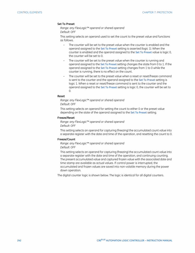
242 C90PLUS AUTOMATION LOGIC CONTROLLER – INSTRUCTION MANUAL
CONTROL ELEMENTS CHAPTER 7: PROTECTION
Set To PresetRange: any FlexLogic™ operand or shared operandDefault: OFF
This setting selects an operand used to set the count to the preset value and functions as follows.
– The counter will be set to the preset value when the counter is enabled and the operand assigned to the Set To Preset setting is asserted (logic 1). When the counter is enabled and the operand assigned to the Set To Preset value is logic 0, the counter will be set to 0.
– The counter will be set to the preset value when the counter is running and operand assigned to the Set To Preset setting changes the state from 0 to 1. If the operand assigned to the Set To Preset setting changes from 1 to 0 while the counter is running, there is no effect on the count.
– The counter will be set to the preset value when a reset or reset/freeze command is sent to the counter and the operand assigned to the Set To Preset setting is logic 1. When a reset or reset/freeze command is sent to the counter and the operand assigned to the Set To Preset setting is logic 0, the counter will be set to 0.
ResetRange: any FlexLogic™ operand or shared operandDefault: OFF
This setting selects an operand for setting the count to either 0 or the preset value depending on the state of the operand assigned to the Set To Preset setting.
Freeze/ResetRange: any FlexLogic™ operand or shared operandDefault: OFF
This setting selects an operand for capturing (freezing) the accumulated count value into a separate register with the date and time of the operation, and resetting the count to 0.
Freeze/CountRange: any FlexLogic™ operand or shared operandDefault: OFF
This setting selects an operand for capturing (freezing) the accumulated count value into a separate register with the date and time of the operation, and continuing counting. The present accumulated value and captured frozen value with the associated date and time stamp are available as actual values. If control power is interrupted, the accumulated and frozen values are saved into non-volatile memory during the power down operation.
The digital counter logic is shown below. The logic is identical for all digital counters.
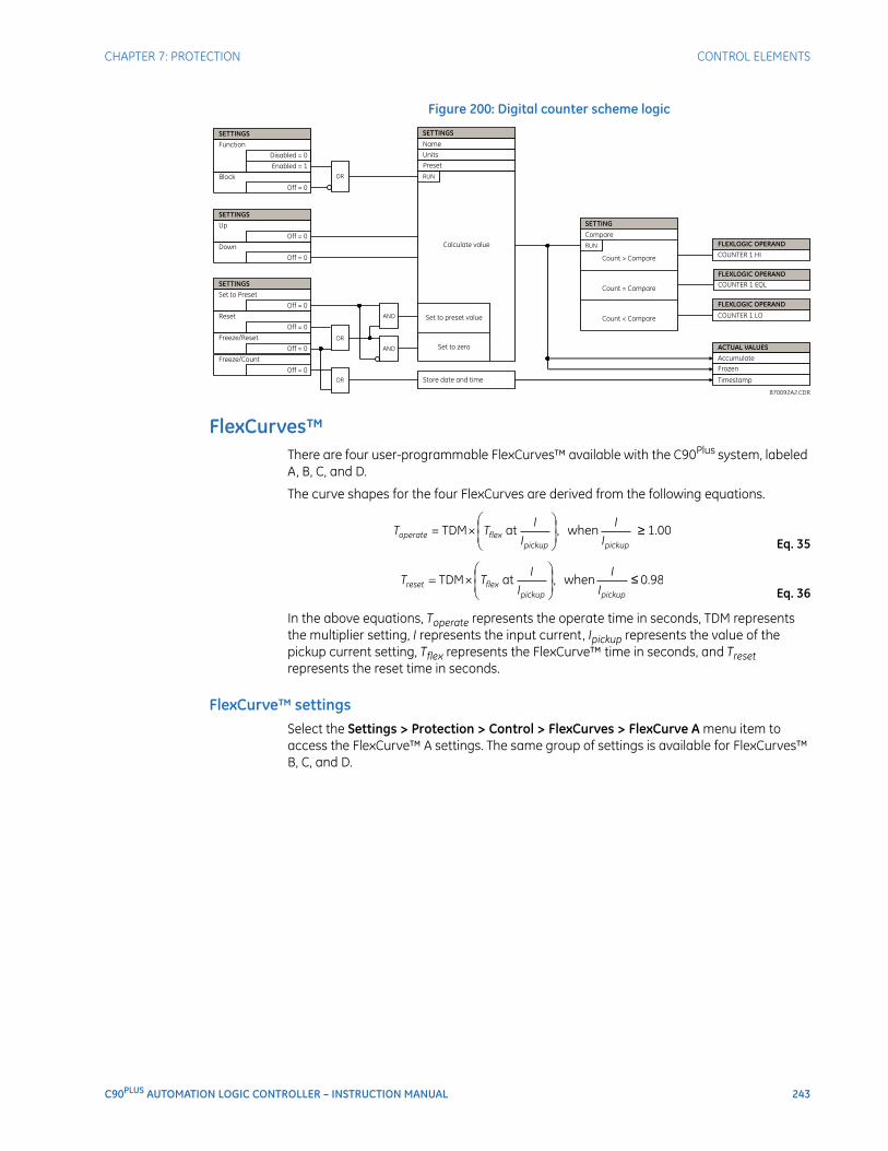
CHAPTER 7: PROTECTION CONTROL ELEMENTS
C90PLUS AUTOMATION LOGIC CONTROLLER – INSTRUCTION MANUAL 243
Figure 200: Digital counter scheme logic
FlexCurves™There are four user-programmable FlexCurves™ available with the C90Plus system, labeled A, B, C, and D.
The curve shapes for the four FlexCurves are derived from the following equations.
Eq. 35
Eq. 36
In the above equations, Toperate represents the operate time in seconds, TDM represents the multiplier setting, I represents the input current, Ipickup represents the value of the pickup current setting, Tflex represents the FlexCurve™ time in seconds, and Treset represents the reset time in seconds.
FlexCurve™ settingsSelect the Settings > Protection > Control > FlexCurves > FlexCurve A menu item to access the FlexCurve™ A settings. The same group of settings is available for FlexCurves™ B, C, and D.
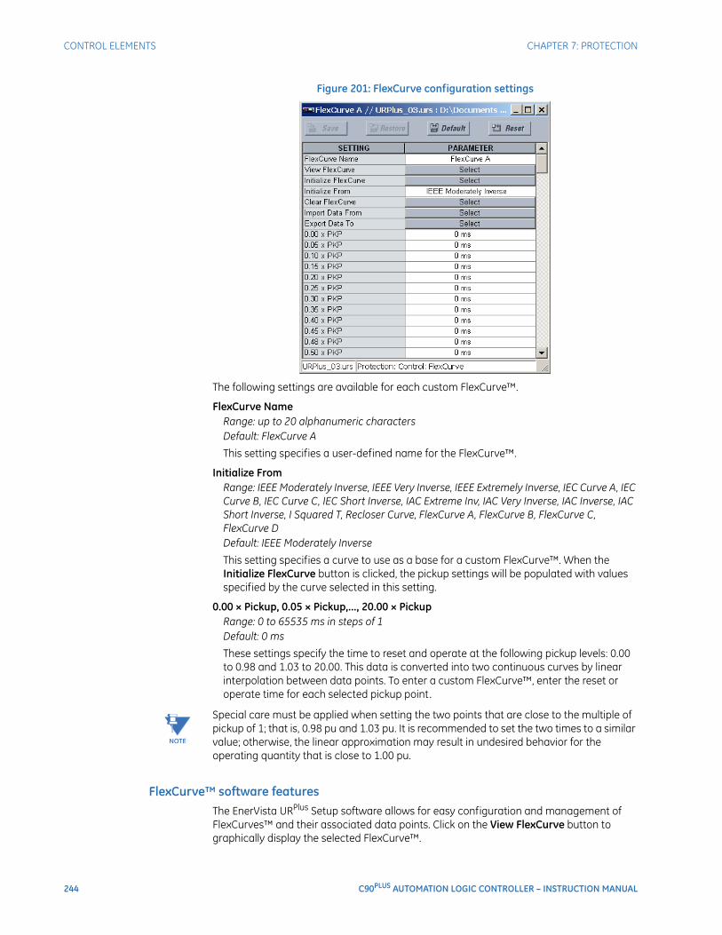
244 C90PLUS AUTOMATION LOGIC CONTROLLER – INSTRUCTION MANUAL
CONTROL ELEMENTS CHAPTER 7: PROTECTION
Figure 201: FlexCurve configuration settings
The following settings are available for each custom FlexCurve™.
FlexCurve NameRange: up to 20 alphanumeric charactersDefault: FlexCurve A
This setting specifies a user-defined name for the FlexCurve™.
Initialize FromRange: IEEE Moderately Inverse, IEEE Very Inverse, IEEE Extremely Inverse, IEC Curve A, IEC Curve B, IEC Curve C, IEC Short Inverse, IAC Extreme Inv, IAC Very Inverse, IAC Inverse, IAC Short Inverse, I Squared T, Recloser Curve, FlexCurve A, FlexCurve B, FlexCurve C, FlexCurve DDefault: IEEE Moderately Inverse
This setting specifies a curve to use as a base for a custom FlexCurve™. When the Initialize FlexCurve button is clicked, the pickup settings will be populated with values specified by the curve selected in this setting.
0.00 × Pickup, 0.05 × Pickup,..., 20.00 × PickupRange: 0 to 65535 ms in steps of 1Default: 0 ms
These settings specify the time to reset and operate at the following pickup levels: 0.00 to 0.98 and 1.03 to 20.00. This data is converted into two continuous curves by linear interpolation between data points. To enter a custom FlexCurve™, enter the reset or operate time for each selected pickup point.
NOTE
NOTE: Special care must be applied when setting the two points that are close to the multiple of pickup of 1; that is, 0.98 pu and 1.03 pu. It is recommended to set the two times to a similar value; otherwise, the linear approximation may result in undesired behavior for the operating quantity that is close to 1.00 pu.
FlexCurve™ software featuresThe EnerVista URPlus Setup software allows for easy configuration and management of FlexCurves™ and their associated data points. Click on the View FlexCurve button to graphically display the selected FlexCurve™.
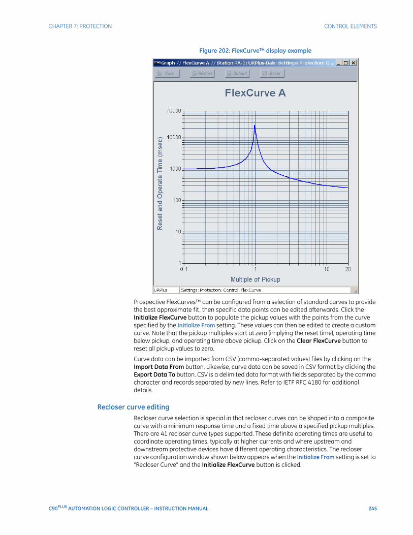
CHAPTER 7: PROTECTION CONTROL ELEMENTS
C90PLUS AUTOMATION LOGIC CONTROLLER – INSTRUCTION MANUAL 245
Figure 202: FlexCurve™ display example
Prospective FlexCurves™ can be configured from a selection of standard curves to provide the best approximate fit , then specific data points can be edited afterwards. Click the Initialize FlexCurve button to populate the pickup values with the points from the curve specified by the Initialize From setting. These values can then be edited to create a custom curve. Note that the pickup multiples start at zero (implying the reset time), operating time below pickup, and operating time above pickup. Click on the Clear FlexCurve button to reset all pickup values to zero.
Curve data can be imported from CSV (comma-separated values) files by clicking on the Import Data From button. Likewise, curve data can be saved in CSV format by clicking the Export Data To button. CSV is a delimited data format with fields separated by the comma character and records separated by new lines. Refer to IETF RFC 4180 for additional details.
Recloser curve editingRecloser curve selection is special in that recloser curves can be shaped into a composite curve with a minimum response time and a fixed time above a specified pickup multiples. There are 41 recloser curve types supported. These definite operating times are useful to coordinate operating times, typically at higher currents and where upstream and downstream protective devices have different operating characteristics. The recloser curve configuration window shown below appears when the Initialize From setting is set to “Recloser Curve” and the Initialize FlexCurve button is clicked.
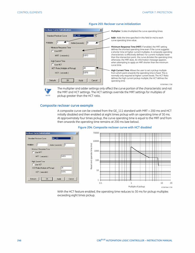
246 C90PLUS AUTOMATION LOGIC CONTROLLER – INSTRUCTION MANUAL
CONTROL ELEMENTS CHAPTER 7: PROTECTION
Figure 203: Recloser curve initialization
NOTE
NOTE: The multiplier and adder settings only affect the curve portion of the characteristic and not the MRT and HCT settings. The HCT settings override the MRT settings for multiples of pickup greater than the HCT ratio.
Composite recloser curve exampleA composite curve can be created from the GE_111 standard with MRT = 200 ms and HCT initially disabled and then enabled at eight times pickup with an operating time of 30 ms. At approximately four times pickup, the curve operating time is equal to the MRT and from then onwards the operating time remains at 200 ms (see below).
Figure 204: Composite recloser curve with HCT disabled
With the HCT feature enabled, the operating time reduces to 30 ms for pickup multiples exceeding eight times pickup.
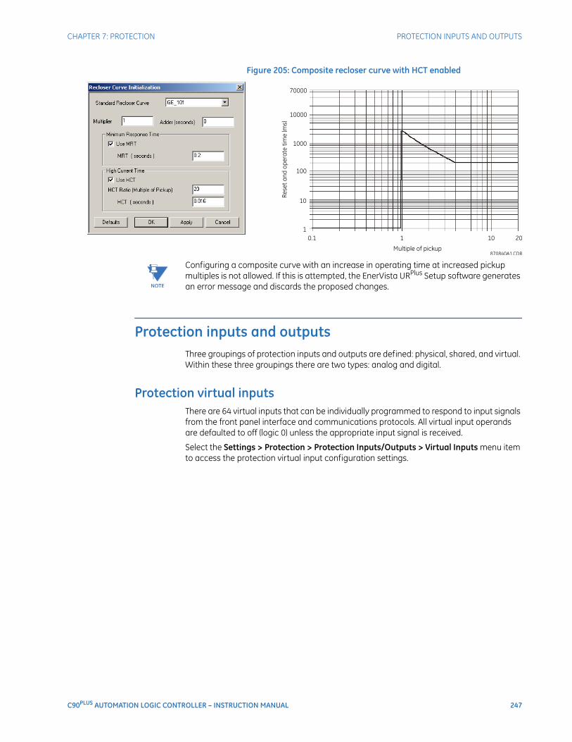
CHAPTER 7: PROTECTION PROTECTION INPUTS AND OUTPUTS
C90PLUS AUTOMATION LOGIC CONTROLLER – INSTRUCTION MANUAL 247
Figure 205: Composite recloser curve with HCT enabled
NOTE
NOTE: Configuring a composite curve with an increase in operating time at increased pickup multiples is not allowed. If this is attempted, the EnerVista URPlus Setup software generates an error message and discards the proposed changes.
Protection inputs and outputsThree groupings of protection inputs and outputs are defined: physical, shared, and virtual. Within these three groupings there are two types: analog and digital.
Protection virtual inputsThere are 64 virtual inputs that can be individually programmed to respond to input signals from the front panel interface and communications protocols. All virtual input operands are defaulted to off (logic 0) unless the appropriate input signal is received.
Select the Settings > Protection > Protection Inputs/Outputs > Virtual Inputs menu item to access the protection virtual input configuration settings.
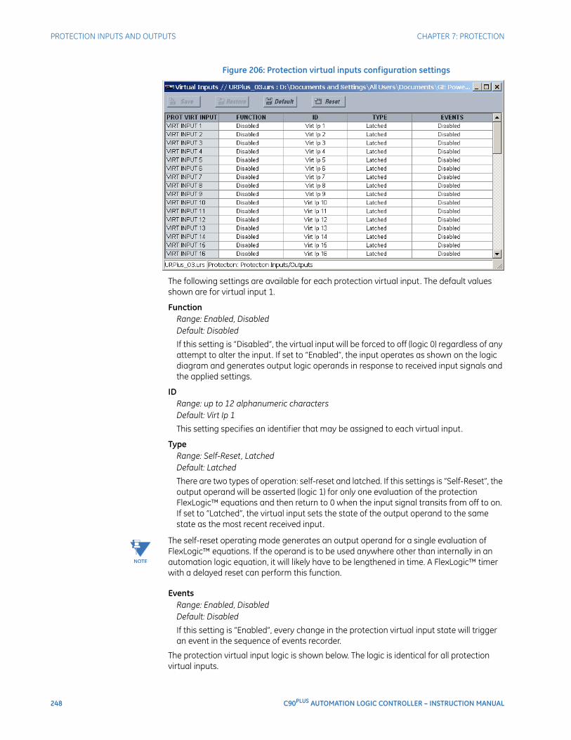
248 C90PLUS AUTOMATION LOGIC CONTROLLER – INSTRUCTION MANUAL
PROTECTION INPUTS AND OUTPUTS CHAPTER 7: PROTECTION
Figure 206: Protection virtual inputs configuration settings
The following settings are available for each protection virtual input. The default values shown are for virtual input 1.
FunctionRange: Enabled, DisabledDefault: Disabled
If this setting is “Disabled”, the virtual input will be forced to off (logic 0) regardless of any attempt to alter the input. If set to “Enabled”, the input operates as shown on the logic diagram and generates output logic operands in response to received input signals and the applied settings.
IDRange: up to 12 alphanumeric charactersDefault: Virt Ip 1
This setting specifies an identifier that may be assigned to each virtual input.
TypeRange: Self-Reset, LatchedDefault: Latched
There are two types of operation: self-reset and latched. If this settings is “Self-Reset”, the output operand will be asserted (logic 1) for only one evaluation of the protection FlexLogic™ equations and then return to 0 when the input signal transits from off to on. If set to “Latched”, the virtual input sets the state of the output operand to the same state as the most recent received input.
NOTE
NOTE: The self-reset operating mode generates an output operand for a single evaluation of FlexLogic™ equations. If the operand is to be used anywhere other than internally in an automation logic equation, it will likely have to be lengthened in time. A FlexLogic™ timer with a delayed reset can perform this function.
EventsRange: Enabled, DisabledDefault: Disabled
If this setting is “Enabled”, every change in the protection virtual input state will trigger an event in the sequence of events recorder.
The protection virtual input logic is shown below. The logic is identical for all protection virtual inputs.
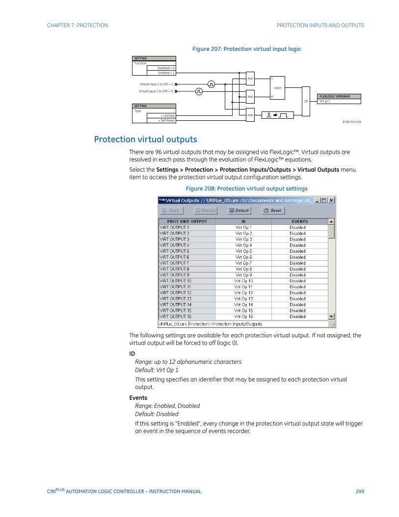
CHAPTER 7: PROTECTION PROTECTION INPUTS AND OUTPUTS
C90PLUS AUTOMATION LOGIC CONTROLLER – INSTRUCTION MANUAL 249
Figure 207: Protection virtual input logic
Protection virtual outputsThere are 96 virtual outputs that may be assigned via FlexLogic™. Virtual outputs are resolved in each pass through the evaluation of FlexLogic™ equations.
Select the Settings > Protection > Protection Inputs/Outputs > Virtual Outputs menu item to access the protection virtual output configuration settings.
Figure 208: Protection virtual output settings
The following settings are available for each protection virtual output. If not assigned, the virtual output will be forced to off (logic 0).
IDRange: up to 12 alphanumeric charactersDefault: Virt Op 1
This setting specifies an identifier that may be assigned to each protection virtual output.
EventsRange: Enabled, DisabledDefault: Disabled
If this setting is “Enabled”, every change in the protection virtual output state will trigger an event in the sequence of events recorder.
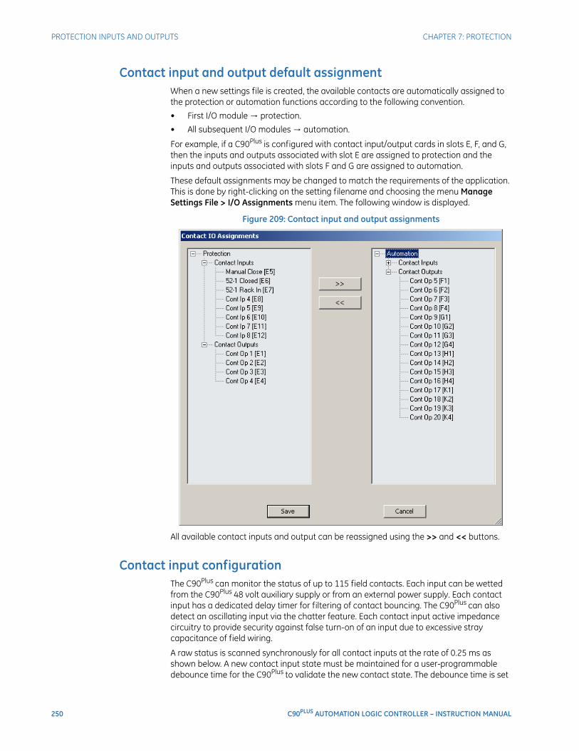
250 C90PLUS AUTOMATION LOGIC CONTROLLER – INSTRUCTION MANUAL
PROTECTION INPUTS AND OUTPUTS CHAPTER 7: PROTECTION
Contact input and output default assignmentWhen a new settings file is created, the available contacts are automatically assigned to the protection or automation functions according to the following convention.
• First I/O module → protection.
• All subsequent I/O modules → automation.
For example, if a C90Plus is configured with contact input/output cards in slots E, F, and G, then the inputs and outputs associated with slot E are assigned to protection and the inputs and outputs associated with slots F and G are assigned to automation.
These default assignments may be changed to match the requirements of the application. This is done by right-clicking on the setting filename and choosing the menu Manage Settings File > I/O Assignments menu item. The following window is displayed.
Figure 209: Contact input and output assignments
All available contact inputs and output can be reassigned using the >> and << buttons.
Contact input configurationThe C90Plus can monitor the status of up to 115 field contacts. Each input can be wetted from the C90Plus 48 volt auxiliary supply or from an external power supply. Each contact input has a dedicated delay timer for filtering of contact bouncing. The C90Plus can also detect an oscillating input via the chatter feature. Each contact input active impedance circuitry to provide security against false turn-on of an input due to excessive stray capacitance of field wiring.
A raw status is scanned synchronously for all contact inputs at the rate of 0.25 ms as shown below. A new contact input state must be maintained for a user-programmable debounce time for the C90Plus to validate the new contact state. The debounce time is set
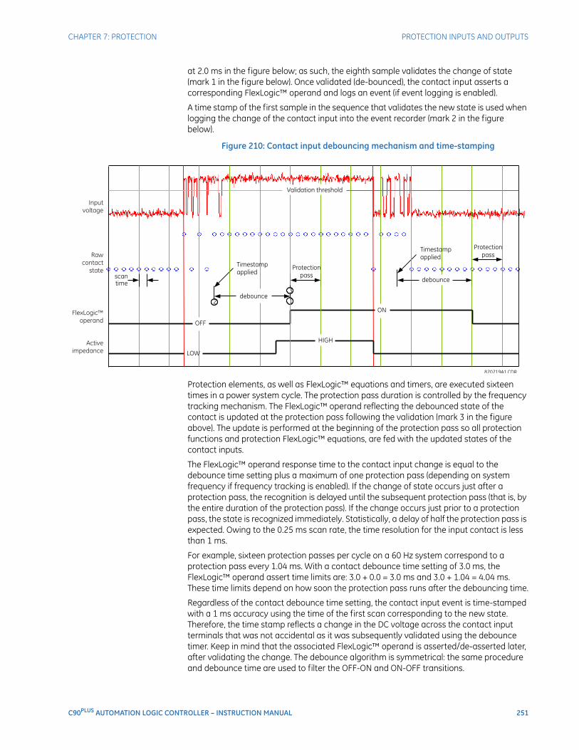
CHAPTER 7: PROTECTION PROTECTION INPUTS AND OUTPUTS
C90PLUS AUTOMATION LOGIC CONTROLLER – INSTRUCTION MANUAL 251
at 2.0 ms in the figure below; as such, the eighth sample validates the change of state (mark 1 in the figure below). Once validated (de-bounced), the contact input asserts a corresponding FlexLogic™ operand and logs an event (if event logging is enabled).
A time stamp of the first sample in the sequence that validates the new state is used when logging the change of the contact input into the event recorder (mark 2 in the figure below).
Figure 210: Contact input debouncing mechanism and time-stamping
Protection elements, as well as FlexLogic™ equations and timers, are executed sixteen times in a power system cycle. The protection pass duration is controlled by the frequency tracking mechanism. The FlexLogic™ operand reflecting the debounced state of the contact is updated at the protection pass following the validation (mark 3 in the figure above). The update is performed at the beginning of the protection pass so all protection functions and protection FlexLogic™ equations, are fed with the updated states of the contact inputs.
The FlexLogic™ operand response time to the contact input change is equal to the debounce time setting plus a maximum of one protection pass (depending on system frequency if frequency tracking is enabled). If the change of state occurs just after a protection pass, the recognition is delayed until the subsequent protection pass (that is, by the entire duration of the protection pass). If the change occurs just prior to a protection pass, the state is recognized immediately. Statistically, a delay of half the protection pass is expected. Owing to the 0.25 ms scan rate, the time resolution for the input contact is less than 1 ms.
For example, sixteen protection passes per cycle on a 60 Hz system correspond to a protection pass every 1.04 ms. With a contact debounce time setting of 3.0 ms, the FlexLogic™ operand assert time limits are: 3.0 + 0.0 = 3.0 ms and 3.0 + 1.04 = 4.04 ms. These time limits depend on how soon the protection pass runs after the debouncing time.
Regardless of the contact debounce time setting, the contact input event is time-stamped with a 1 ms accuracy using the time of the first scan corresponding to the new state. Therefore, the time stamp reflects a change in the DC voltage across the contact input terminals that was not accidental as it was subsequently validated using the debounce timer. Keep in mind that the associated FlexLogic™ operand is asserted/de-asserted later, after validating the change. The debounce algorithm is symmetrical: the same procedure and debounce time are used to filter the OFF-ON and ON-OFF transitions.
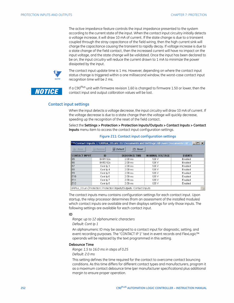
252 C90PLUS AUTOMATION LOGIC CONTROLLER – INSTRUCTION MANUAL
PROTECTION INPUTS AND OUTPUTS CHAPTER 7: PROTECTION
The active impedance feature controls the input impedance presented to the system according to the current state of the input. When the contact input circuitry initially detects a voltage increase, it will draw 10 mA of current. If the state change is due to a transient coupled through the stray capacitance of the field wiring, then the high current sink will charge the capacitance causing the transient to rapidly decay. If voltage increase is due to a state change of the field contact, then the increased current will have no impact on the input voltage, and the state change will be validated. Once the input has been declared to be on, the input circuitry will reduce the current drawn to 1 mA to minimize the power dissipated by the input.
NOTE
NOTE: The contact input update time is 1 ms. However, depending on where the contact input status change is triggered within a one millisecond window, the worst-case contact input recognition time will be 2 ms.
FASTPATH: If a C90Plus unit with firmware revision 1.60 is changed to firmware 1.50 or lower, then the contact input and output calibration values will be lost.
Contact input settingsWhen the input detects a voltage decrease, the input circuitry will draw 10 mA of current. If the voltage decrease is due to a state change then the voltage will quickly decrease, speeding up the recognition of the reset of the field contact.
Select the Settings > Protection > Protection Inputs/Outputs > Contact Inputs > Contact Inputs menu item to access the contact input configuration settings.
Figure 211: Contact input configuration settings
The contact inputs menu contains configuration settings for each contact input. Upon startup, the relay processor determines (from an assessment of the installed modules) which contact inputs are available and then displays settings for only those inputs. The following settings are available for each contact input.
IDRange: up to 12 alphanumeric charactersDefault: Cont Ip 1
An alphanumeric ID may be assigned to a contact input for diagnostic, setting, and event recording purposes. The “CONTACT IP 1” text in event records and FlexLogic™ operands will be replaced by the text programmed in this setting.
Debounce TimeRange: 1.5 to 16.0 ms in steps of 0.25Default: 2.0 ms
This setting defines the time required for the contact to overcome contact bouncing conditions. As this time differs for different contact types and manufacturers, program it as a maximum contact debounce time (per manufacturer specifications) plus additional margin to ensure proper operation.
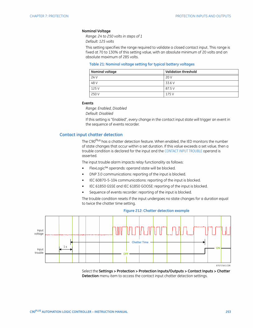
CHAPTER 7: PROTECTION PROTECTION INPUTS AND OUTPUTS
C90PLUS AUTOMATION LOGIC CONTROLLER – INSTRUCTION MANUAL 253
Nominal VoltageRange: 24 to 250 volts in steps of 1Default: 125 volts
This setting specifies the range required to validate a closed contact input. This range is fixed at 70 to 130% of this setting value, with an absolute minimum of 20 volts and an absolute maximum of 285 volts.
Table 21: Nominal voltage setting for typical battery voltages
EventsRange: Enabled, DisabledDefault: Disabled
If this setting is “Enabled”, every change in the contact input state will trigger an event in the sequence of events recorder.
Contact input chatter detectionThe C90Plus has a chatter detection feature. When enabled, the IED monitors the number of state changes that occur within a set duration. If this value exceeds a set value, then a trouble condition is declared for the input and the CONTACT INPUT TROUBLE operand is asserted.
The input trouble alarm impacts relay functionality as follows:
• FlexLogic™ operands: operand state will be blocked.
• DNP 3.0 communications: reporting of the input is blocked.
• IEC 60870-5-104 communications: reporting of the input is blocked.
• IEC 61850 GSSE and IEC 61850 GOOSE: reporting of the input is blocked.
• Sequence of events recorder: reporting of the input is blocked.
The trouble condition resets if the input undergoes no state changes for a duration equal to twice the chatter time setting.
Figure 212: Chatter detection example
Select the Settings > Protection > Protection Inputs/Outputs > Contact Inputs > Chatter Detection menu item to access the contact input chatter detection settings.
Nominal voltage Validation threshold
24 V 20 V
48 V 33.6 V
125 V 87.5 V
250 V 175 V
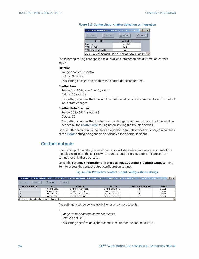
254 C90PLUS AUTOMATION LOGIC CONTROLLER – INSTRUCTION MANUAL
PROTECTION INPUTS AND OUTPUTS CHAPTER 7: PROTECTION
Figure 213: Contact input chatter detection configuration
The following settings are applied to all available protection and automation contact inputs.
FunctionRange: Enabled, DisabledDefault: Disabled
This setting enables and disables the chatter detection feature.
Chatter TimeRange: 1 to 100 seconds in steps of 1Default: 10 seconds
This setting specifies the time window that the relay contacts are monitored for contact input state changes.
Chatter State ChangesRange: 10 to 100 in steps of 1Default: 30
This setting specifies the number of state changes that must occur in the time window defined by the Chatter Time setting before issuing the trouble operand.
Since chatter detection is a hardware diagnostic, a trouble indication is logged regardless of the Events setting being enabled or disabled for a particular input.
Contact outputsUpon startup of the relay, the main processor will determine from an assessment of the modules installed in the chassis which contact outputs are available and present the settings for only these outputs.
Select the Settings > Protection > Protection Inputs/Outputs > Contact Outputs menu item to access the contact output configuration settings.
Figure 214: Protection contact output configuration settings
The settings listed below are available for all contact outputs.
IDRange: up to 12 alphanumeric charactersDefault: Cont Op 1
This setting specifies an alphanumeric identifier for the contact output.

CHAPTER 7: PROTECTION PROTECTION INPUTS AND OUTPUTS
C90PLUS AUTOMATION LOGIC CONTROLLER – INSTRUCTION MANUAL 255
OperateRange: any FlexLogic™ operand or shared operandDefault: as shown above
This setting selects an operand (virtual output, element state, contact input, or virtual input) that will operate the contact output when asserted.
Seal-InRange: any FlexLogic™ operand or shared operandDefault: as shown above
This setting selects an operand (virtual output, element state, contact input, or virtual input) that will seal-in the contact output when asserted.
Voltage ThresholdRange: 20 to 250 volts in steps of 1Default: 20
This setting specifies determines the level at which the Contact Op 1 VOn and Contact Op 1 VOff operands function. It is only shown for contact outputs that have monitoring.
EventsRange: Enabled, DisabledDefault: Enabled
If this setting is “Enabled”, every change in the contact output state will trigger an event in the sequence of events recorder.
Shared operandsThe EnerVista URPlus Setup software groups the C90Plus system into the following seven primary functions. Each function has its own setting parameters and each generates its own outputs in the form of operands.
• Protection.
• Automation.
• Metering.
• Communications.
• Digital fault recorder (DFR).
• Equipment manager.
• Front panel interface (HMI).
However, it is often desirable for an output from an element within one function can be available to an element within another function. For instance, it may be useful for the digital fault recorder to record the output operands of any protection element. Consequently a fixed, predetermined set of operands is available as to each function as shown below.
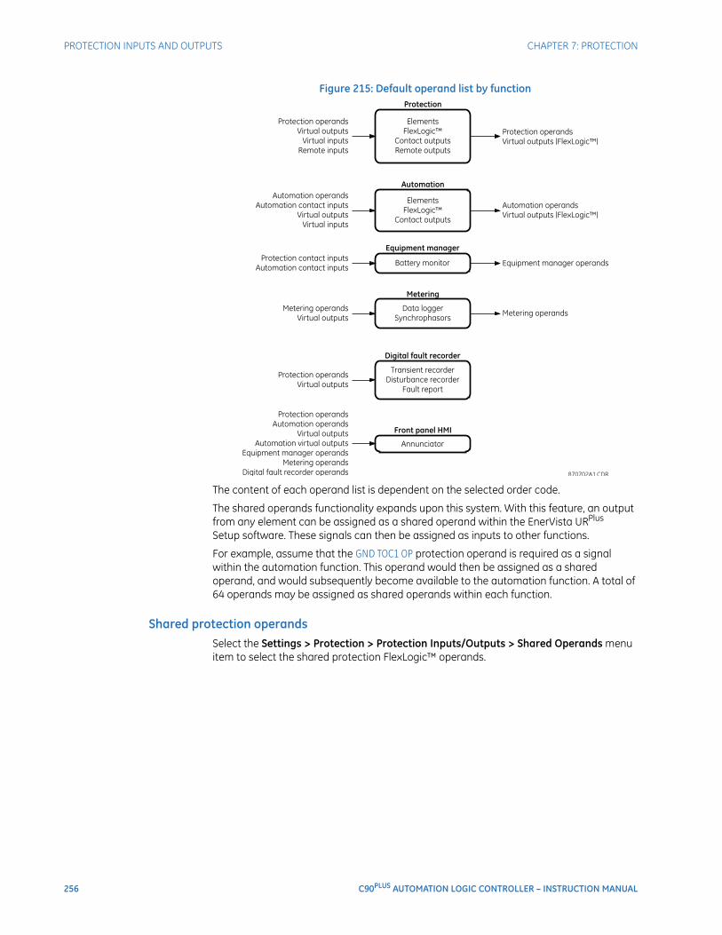
256 C90PLUS AUTOMATION LOGIC CONTROLLER – INSTRUCTION MANUAL
PROTECTION INPUTS AND OUTPUTS CHAPTER 7: PROTECTION
Figure 215: Default operand list by function
The content of each operand list is dependent on the selected order code.
The shared operands functionality expands upon this system. With this feature, an output from any element can be assigned as a shared operand within the EnerVista URPlus Setup software. These signals can then be assigned as inputs to other functions.
For example, assume that the GND TOC1 OP protection operand is required as a signal within the automation function. This operand would then be assigned as a shared operand, and would subsequently become available to the automation function. A total of 64 operands may be assigned as shared operands within each function.
Shared protection operandsSelect the Settings > Protection > Protection Inputs/Outputs > Shared Operands menu item to select the shared protection FlexLogic™ operands.
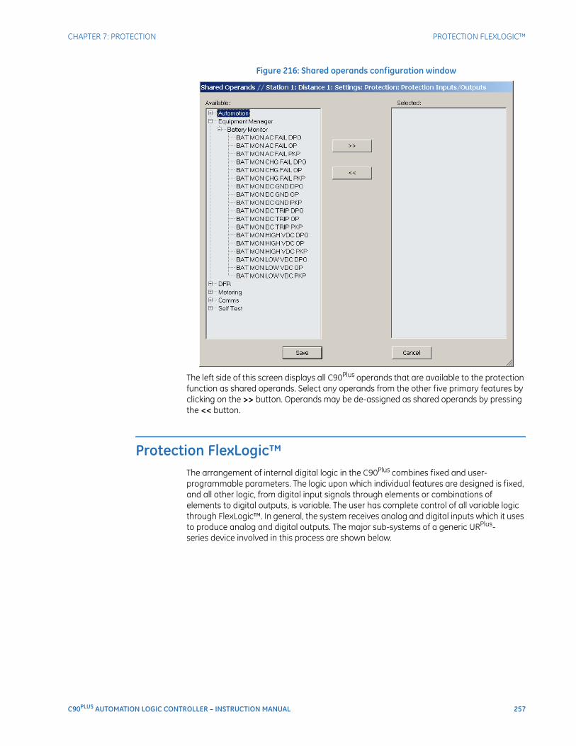
CHAPTER 7: PROTECTION PROTECTION FLEXLOGIC™
C90PLUS AUTOMATION LOGIC CONTROLLER – INSTRUCTION MANUAL 257
Figure 216: Shared operands configuration window
The left side of this screen displays all C90Plus operands that are available to the protection function as shared operands. Select any operands from the other five primary features by clicking on the >> button. Operands may be de-assigned as shared operands by pressing the << button.
Protection FlexLogic™The arrangement of internal digital logic in the C90Plus combines fixed and user-programmable parameters. The logic upon which individual features are designed is fixed, and all other logic, from digital input signals through elements or combinations of elements to digital outputs, is variable. The user has complete control of all variable logic through FlexLogic™. In general, the system receives analog and digital inputs which it uses to produce analog and digital outputs. The major sub-systems of a generic URPlus-series device involved in this process are shown below.
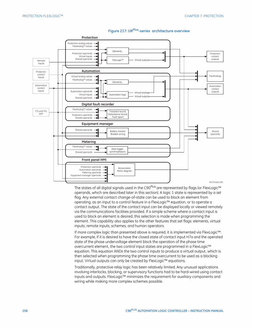
258 C90PLUS AUTOMATION LOGIC CONTROLLER – INSTRUCTION MANUAL
PROTECTION FLEXLOGIC™ CHAPTER 7: PROTECTION
Figure 217: URPlus-series architecture overview
The states of all digital signals used in the C90Plus are represented by flags (or FlexLogic™ operands, which are described later in this section). A logic 1 state is represented by a set flag. Any external contact change-of-state can be used to block an element from operating, as an input to a control feature in a FlexLogic™ equation, or to operate a contact output. The state of the contact input can be displayed locally or viewed remotely via the communications facilities provided. If a simple scheme where a contact input is used to block an element is desired, this selection is made when programming the element. This capability also applies to the other features that set flags: elements, virtual inputs, remote inputs, schemes, and human operators.
If more complex logic than presented above is required, it is implemented via FlexLogic™. For example, if it is desired to have the closed state of contact input H7a and the operated state of the phase undervoltage element block the operation of the phase time overcurrent element, the two control input states are programmed in a FlexLogic™ equation. This equation ANDs the two control inputs to produce a virtual output, which is then selected when programming the phase time overcurrent to be used as a blocking input. Virtual outputs can only be created by FlexLogic™ equations.
Traditionally, protective relay logic has been relatively limited. Any unusual applications involving interlocks, blocking, or supervisory functions had to be hard-wired using contact inputs and outputs. FlexLogic™ minimizes the requirement for auxiliary components and wiring while making more complex schemes possible.
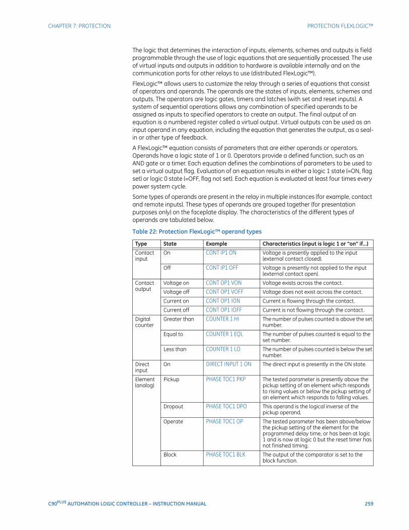
CHAPTER 7: PROTECTION PROTECTION FLEXLOGIC™
C90PLUS AUTOMATION LOGIC CONTROLLER – INSTRUCTION MANUAL 259
The logic that determines the interaction of inputs, elements, schemes and outputs is field programmable through the use of logic equations that are sequentially processed. The use of virtual inputs and outputs in addition to hardware is available internally and on the communication ports for other relays to use (distributed FlexLogic™).
FlexLogic™ allows users to customize the relay through a series of equations that consist of operators and operands. The operands are the states of inputs, elements, schemes and outputs. The operators are logic gates, timers and latches (with set and reset inputs). A system of sequential operations allows any combination of specified operands to be assigned as inputs to specified operators to create an output. The final output of an equation is a numbered register called a virtual output. Virtual outputs can be used as an input operand in any equation, including the equation that generates the output, as a seal-in or other type of feedback.
A FlexLogic™ equation consists of parameters that are either operands or operators. Operands have a logic state of 1 or 0. Operators provide a defined function, such as an AND gate or a timer. Each equation defines the combinations of parameters to be used to set a virtual output flag. Evaluation of an equation results in either a logic 1 state (=ON, flag set) or logic 0 state (=OFF, flag not set). Each equation is evaluated at least four times every power system cycle.
Some types of operands are present in the relay in multiple instances (for example, contact and remote inputs). These types of operands are grouped together (for presentation purposes only) on the faceplate display. The characteristics of the different types of operands are tabulated below.
Table 22: Protection FlexLogic™ operand types
Type State Example Characteristics (input is logic 1 or “on” if...)
Contact input
On CONT IP1 ON Voltage is presently applied to the input (external contact closed).
Off CONT IP1 OFF Voltage is presently not applied to the input (external contact open).
Contact output
Voltage on CONT OP1 VON Voltage exists across the contact.
Voltage off CONT OP1 VOFF Voltage does not exist across the contact.
Current on CONT OP1 ION Current is flowing through the contact.
Current off CONT OP1 IOFF Current is not flowing through the contact.
Digital counter
Greater than COUNTER 1 HI The number of pulses counted is above the set number.
Equal to COUNTER 1 EQL The number of pulses counted is equal to the set number.
Less than COUNTER 1 LO The number of pulses counted is below the set number.
Direct input
On DIRECT INPUT 1 ON The direct input is presently in the ON state.
Element (analog)
Pickup PHASE TOC1 PKP The tested parameter is presently above the pickup setting of an element which responds to rising values or below the pickup setting of an element which responds to falling values.
Dropout PHASE TOC1 DPO This operand is the logical inverse of the pickup operand.
Operate PHASE TOC1 OP The tested parameter has been above/below the pickup setting of the element for the programmed delay time, or has been at logic 1 and is now at logic 0 but the reset timer has not finished timing.
Block PHASE TOC1 BLK The output of the comparator is set to the block function.
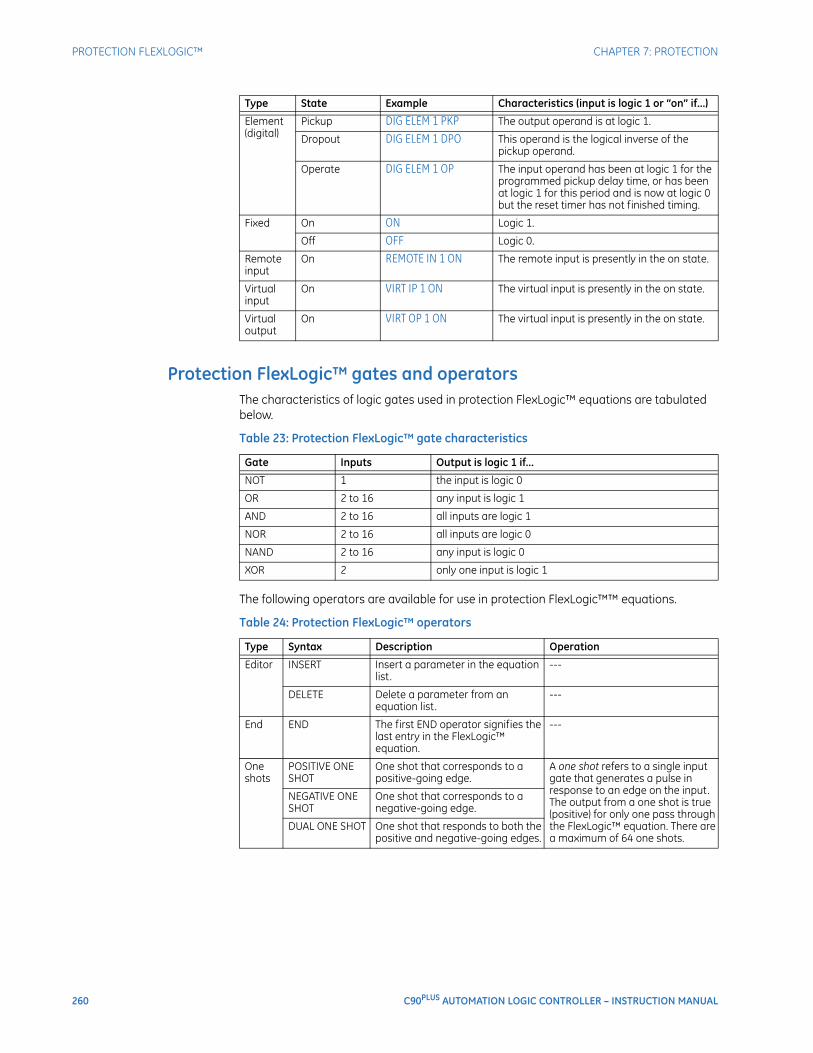
260 C90PLUS AUTOMATION LOGIC CONTROLLER – INSTRUCTION MANUAL
PROTECTION FLEXLOGIC™ CHAPTER 7: PROTECTION
Protection FlexLogic™ gates and operatorsThe characteristics of logic gates used in protection FlexLogic™ equations are tabulated below.
Table 23: Protection FlexLogic™ gate characteristics
The following operators are available for use in protection FlexLogic™™ equations.
Table 24: Protection FlexLogic™ operators
Element (digital)
Pickup DIG ELEM 1 PKP The output operand is at logic 1.
Dropout DIG ELEM 1 DPO This operand is the logical inverse of the pickup operand.
Operate DIG ELEM 1 OP The input operand has been at logic 1 for the programmed pickup delay time, or has been at logic 1 for this period and is now at logic 0 but the reset timer has not finished timing.
Fixed On ON Logic 1.
Off OFF Logic 0.
Remote input
On REMOTE IN 1 ON The remote input is presently in the on state.
Virtual input
On VIRT IP 1 ON The virtual input is presently in the on state.
Virtual output
On VIRT OP 1 ON The virtual input is presently in the on state.
Type State Example Characteristics (input is logic 1 or “on” if...)
Gate Inputs Output is logic 1 if...
NOT 1 the input is logic 0
OR 2 to 16 any input is logic 1
AND 2 to 16 all inputs are logic 1
NOR 2 to 16 all inputs are logic 0
NAND 2 to 16 any input is logic 0
XOR 2 only one input is logic 1
Type Syntax Description Operation
Editor INSERT Insert a parameter in the equation list.
---
DELETE Delete a parameter from an equation list.
---
End END The first END operator signifies the last entry in the FlexLogic™ equation.
---
One shots
POSITIVE ONE SHOT
One shot that corresponds to a positive-going edge.
A one shot refers to a single input gate that generates a pulse in response to an edge on the input. The output from a one shot is true (positive) for only one pass through the FlexLogic™ equation. There are a maximum of 64 one shots.
NEGATIVE ONE SHOT
One shot that corresponds to a negative-going edge.
DUAL ONE SHOT One shot that responds to both the positive and negative-going edges.
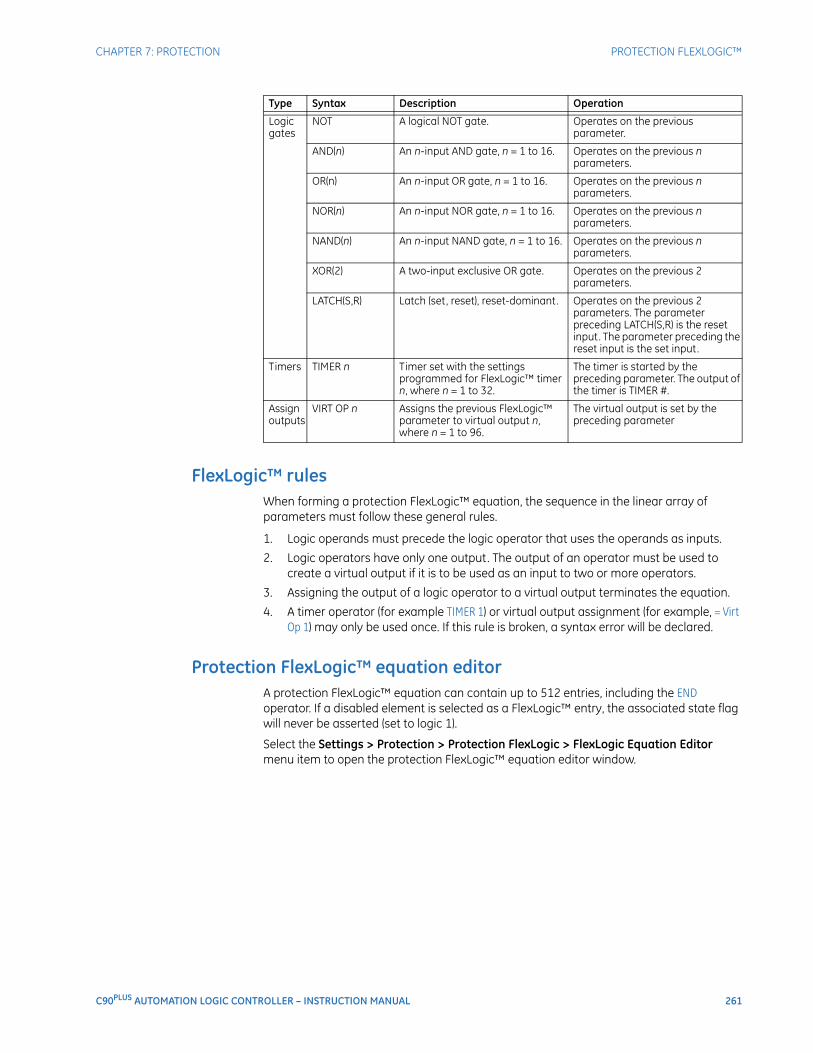
CHAPTER 7: PROTECTION PROTECTION FLEXLOGIC™
C90PLUS AUTOMATION LOGIC CONTROLLER – INSTRUCTION MANUAL 261
FlexLogic™ rulesWhen forming a protection FlexLogic™ equation, the sequence in the linear array of parameters must follow these general rules.
1. Logic operands must precede the logic operator that uses the operands as inputs.
2. Logic operators have only one output. The output of an operator must be used to create a virtual output if it is to be used as an input to two or more operators.
3. Assigning the output of a logic operator to a virtual output terminates the equation.
4. A timer operator (for example TIMER 1) or virtual output assignment (for example, = Virt Op 1) may only be used once. If this rule is broken, a syntax error will be declared.
Protection FlexLogic™ equation editorA protection FlexLogic™ equation can contain up to 512 entries, including the END operator. If a disabled element is selected as a FlexLogic™ entry, the associated state flag will never be asserted (set to logic 1).
Select the Settings > Protection > Protection FlexLogic > FlexLogic Equation Editor menu item to open the protection FlexLogic™ equation editor window.
Logic gates
NOT A logical NOT gate. Operates on the previous parameter.
AND(n) An n-input AND gate, n = 1 to 16. Operates on the previous n parameters.
OR(n) An n-input OR gate, n = 1 to 16. Operates on the previous n parameters.
NOR(n) An n-input NOR gate, n = 1 to 16. Operates on the previous n parameters.
NAND(n) An n-input NAND gate, n = 1 to 16. Operates on the previous n parameters.
XOR(2) A two-input exclusive OR gate. Operates on the previous 2 parameters.
LATCH(S,R) Latch (set, reset), reset-dominant. Operates on the previous 2 parameters. The parameter preceding LATCH(S,R) is the reset input. The parameter preceding the reset input is the set input.
Timers TIMER n Timer set with the settings programmed for FlexLogic™ timer n, where n = 1 to 32.
The timer is started by the preceding parameter. The output of the timer is TIMER #.
Assign outputs
VIRT OP n Assigns the previous FlexLogic™ parameter to virtual output n, where n = 1 to 96.
The virtual output is set by the preceding parameter
Type Syntax Description Operation
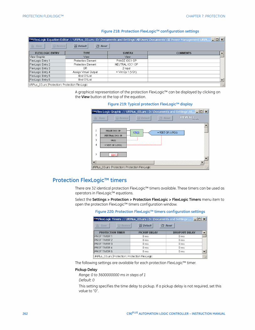
262 C90PLUS AUTOMATION LOGIC CONTROLLER – INSTRUCTION MANUAL
PROTECTION FLEXLOGIC™ CHAPTER 7: PROTECTION
Figure 218: Protection FlexLogic™ configuration settings
A graphical representation of the protection FlexLogic™ can be displayed by clicking on the View button at the top of the equation.
Figure 219: Typical protection FlexLogic™ display
Protection FlexLogic™ timersThere are 32 identical protection FlexLogic™ timers available. These timers can be used as operators in FlexLogic™ equations.
Select the Settings > Protection > Protection FlexLogic > FlexLogic Timers menu item to open the protection FlexLogic™ timers configuration window.
Figure 220: Protection FlexLogic™ timers configuration settings
The following settings are available for each protection FlexLogic™ timer.
Pickup DelayRange: 0 to 3600000000 ms in steps of 1Default: 0
This setting specifies the time delay to pickup. If a pickup delay is not required, set this value to “0”.

CHAPTER 7: PROTECTION PROTECTION FLEXLOGIC™
C90PLUS AUTOMATION LOGIC CONTROLLER – INSTRUCTION MANUAL 263
Dropout DelayRange: 0 to 3600000000 ms in steps of 1Default: 0
This setting specifies the time delay to dropout. If a dropout delay is not required, set this value to “0”.
Non-volatile latchesThe non-volatile latches provide a permanent logical flag that is stored safely and will not reset upon reboot after the relay is powered down. Typical applications include sustaining operator commands or permanently block relay functions, such as autoreclose, until a deliberate interface action resets the latch. There are 16 non-volatile latches available for use in protection schemes.
Select the Settings > Protection > Protection FlexLogic > Non-Volatile Latches menu item to open the non-volatile latches configuration window.
Figure 221: Non-volatile latches configuration settings
The following settings are available for the protection non-volatile latches.
FunctionRange: Enabled, DisabledDefault: Disabled
This setting enables and disables the corresponding protection non-volatile latch.
TypeRange: Reset Dominant, Set DominantDefault: Reset Dominant
This setting selects the non-volatile latch as set-dominant or reset-dominant.
SetRange: any FlexLogic™ operand or shared operandDefault: OFF
If the operand assigned to this setting is asserted, the non-volatile latch will be set.
ResetRange: any FlexLogic™ operand or shared operandDefault: OFF
If the operand assigned to this setting is asserted, the non-volatile latch will be reset.
EventsRange: Enabled, DisabledDefault: Disabled
This setting enables and disables the logging of non-volatile latch events in the sequence of events recorder.
The following table summarizes the operation of the non-volatile latches.
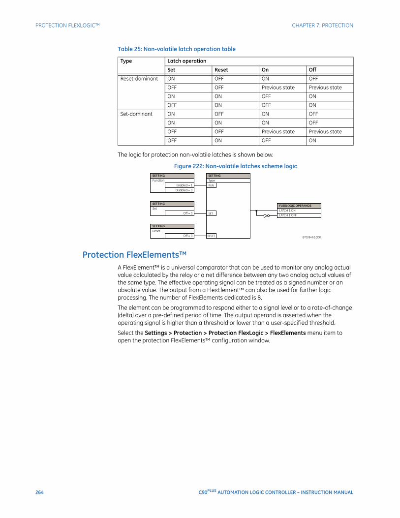
264 C90PLUS AUTOMATION LOGIC CONTROLLER – INSTRUCTION MANUAL
PROTECTION FLEXLOGIC™ CHAPTER 7: PROTECTION
Table 25: Non-volatile latch operation table
The logic for protection non-volatile latches is shown below.
Figure 222: Non-volatile latches scheme logic
Protection FlexElements™A FlexElement™ is a universal comparator that can be used to monitor any analog actual value calculated by the relay or a net difference between any two analog actual values of the same type. The effective operating signal can be treated as a signed number or an absolute value. The output from a FlexElement™ can also be used for further logic processing. The number of FlexElements dedicated is 8.
The element can be programmed to respond either to a signal level or to a rate-of-change (delta) over a pre-defined period of time. The output operand is asserted when the operating signal is higher than a threshold or lower than a user-specified threshold.
Select the Settings > Protection > Protection FlexLogic > FlexElements menu item to open the protection FlexElements™ configuration window.
Type Latch operation
Set Reset On Off
Reset-dominant ON OFF ON OFF
OFF OFF Previous state Previous state
ON ON OFF ON
OFF ON OFF ON
Set-dominant ON OFF ON OFF
ON ON ON OFF
OFF OFF Previous state Previous state
OFF ON OFF ON
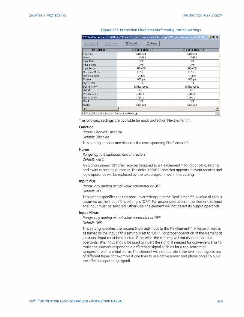
CHAPTER 7: PROTECTION PROTECTION FLEXLOGIC™
C90PLUS AUTOMATION LOGIC CONTROLLER – INSTRUCTION MANUAL 265
Figure 223: Protection FlexElements™ configuration settings
The following settings are available for each protection FlexElement™.
FunctionRange: Enabled, DisabledDefault: Disabled
This setting enables and disables the corresponding FlexElement™.
NameRange: up to 6 alphanumeric charactersDefault: FxE 1
An alphanumeric identifier may be assigned to a FlexElement™ for diagnostic, setting, and event recording purposes. The default “FxE 1” text that appears in event records and logic operands will be replaced by the text programmed in this setting.
Input PlusRange: any analog actual value parameter or OFFDefault: OFF
This setting specifies the first (non-inverted) input to the FlexElement™. A value of zero is assumed as the input if this setting is “OFF”. For proper operation of the element, at least one input must be selected. Otherwise, the element will not assert its output operands.
Input MinusRange: any analog actual value parameter or OFFDefault: OFF
This setting specifies the second (inverted) input to the FlexElement™. A value of zero is assumed as the input if this setting is set to “OFF”. For proper operation of the element at least one input must be selected. Otherwise, the element will not assert its output operands. This input should be used to invert the signal if needed for convenience, or to make the element respond to a differential signal such as for a top-bottom oil temperature differential alarm. The element will not operate if the two input signals are of different types (for example if one tries to use active power and phase angle to build the effective operating signal).

266 C90PLUS AUTOMATION LOGIC CONTROLLER – INSTRUCTION MANUAL
PROTECTION FLEXLOGIC™ CHAPTER 7: PROTECTION
Input ModeRange: Signed, AbsoluteDefault: Signed
If this setting value is “Signed”, then the FlexElement™ responds directly to the differential signal. If this setting value is “Absolute”, then the FlexElement™ responds to the absolute value of the differential signal. Sample applications for the absolute input mode include monitoring the angular difference between two phasors with a symmetrical limit angle in both directions, monitoring power regardless of its direction, or monitoring a trend regardless of whether the signal increases of decreases.
Compare ModeRange: Level, DeltaDefault: Level
This setting specifies how the element responds to its operating signal. If this setting value is “Level”, the element responds directly to its operating signal (as defined by the Input Plus, Input Minus, and Input Mode settings). If this setting value if “Delta”, the element responds to the rate of change of its operating signal (as defined by the Delta T and Delta T Units settings).
Direction TypeRange: Over, UnderDefault: Over
This setting enables the relay to respond to either high or low values of the operating signal.
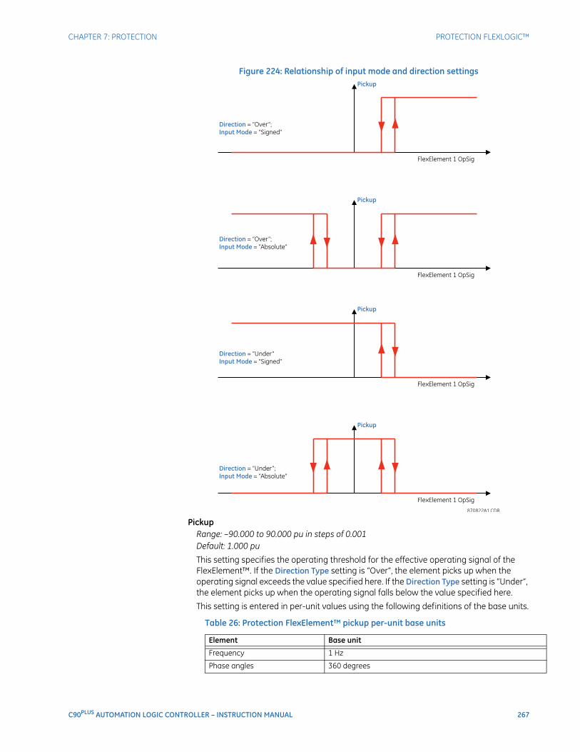
CHAPTER 7: PROTECTION PROTECTION FLEXLOGIC™
C90PLUS AUTOMATION LOGIC CONTROLLER – INSTRUCTION MANUAL 267
Figure 224: Relationship of input mode and direction settings
PickupRange: –90.000 to 90.000 pu in steps of 0.001Default: 1.000 pu
This setting specifies the operating threshold for the effective operating signal of the FlexElement™. If the Direction Type setting is “Over”, the element picks up when the operating signal exceeds the value specified here. If the Direction Type setting is “Under”, the element picks up when the operating signal falls below the value specified here.
This setting is entered in per-unit values using the following definitions of the base units.
Table 26: Protection FlexElement™ pickup per-unit base units
Element Base unit
Frequency 1 Hz
Phase angles 360 degrees
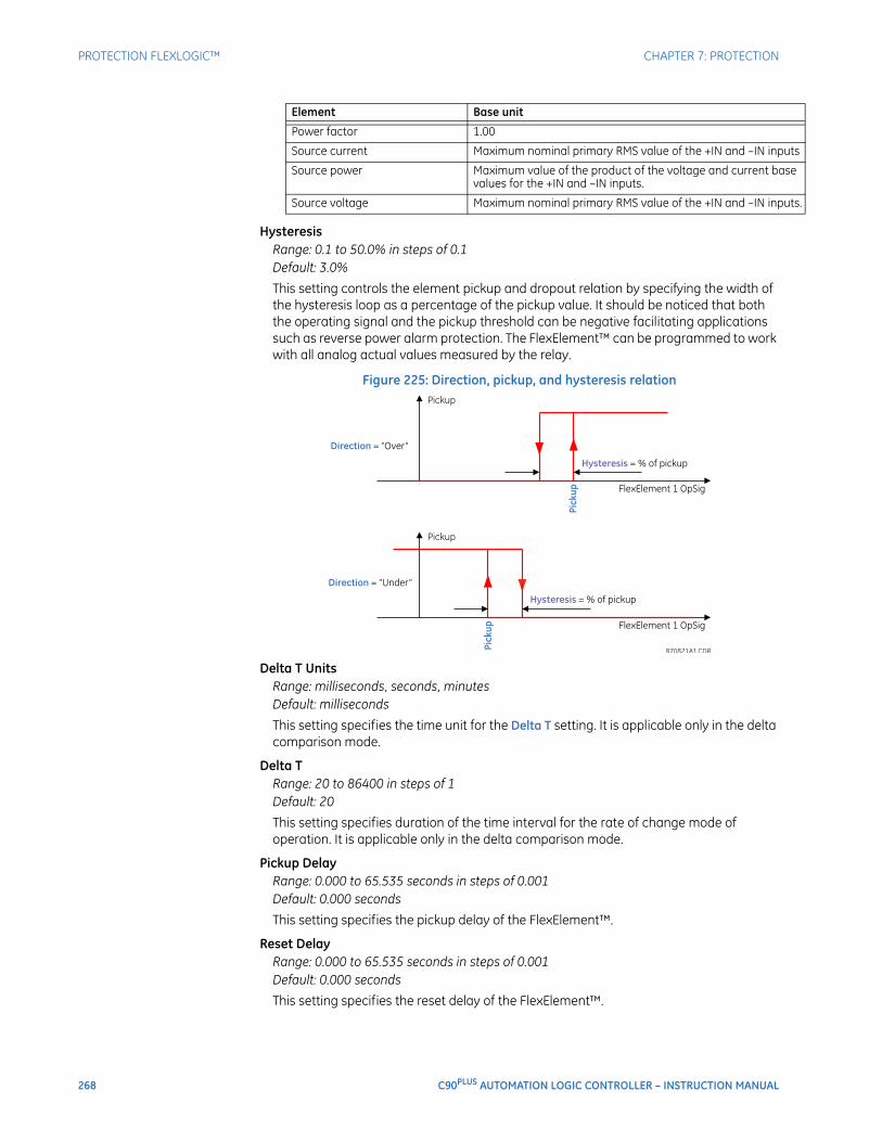
268 C90PLUS AUTOMATION LOGIC CONTROLLER – INSTRUCTION MANUAL
PROTECTION FLEXLOGIC™ CHAPTER 7: PROTECTION
HysteresisRange: 0.1 to 50.0% in steps of 0.1Default: 3.0%
This setting controls the element pickup and dropout relation by specifying the width of the hysteresis loop as a percentage of the pickup value. It should be noticed that both the operating signal and the pickup threshold can be negative facilitating applications such as reverse power alarm protection. The FlexElement™ can be programmed to work with all analog actual values measured by the relay.
Figure 225: Direction, pickup, and hysteresis relation
Delta T UnitsRange: milliseconds, seconds, minutesDefault: milliseconds
This setting specifies the time unit for the Delta T setting. It is applicable only in the delta comparison mode.
Delta TRange: 20 to 86400 in steps of 1Default: 20
This setting specifies duration of the time interval for the rate of change mode of operation. It is applicable only in the delta comparison mode.
Pickup DelayRange: 0.000 to 65.535 seconds in steps of 0.001Default: 0.000 seconds
This setting specifies the pickup delay of the FlexElement™.
Reset DelayRange: 0.000 to 65.535 seconds in steps of 0.001Default: 0.000 seconds
This setting specifies the reset delay of the FlexElement™.
Power factor 1.00
Source current Maximum nominal primary RMS value of the +IN and –IN inputs
Source power Maximum value of the product of the voltage and current base values for the +IN and –IN inputs.
Source voltage Maximum nominal primary RMS value of the +IN and –IN inputs.
Element Base unit
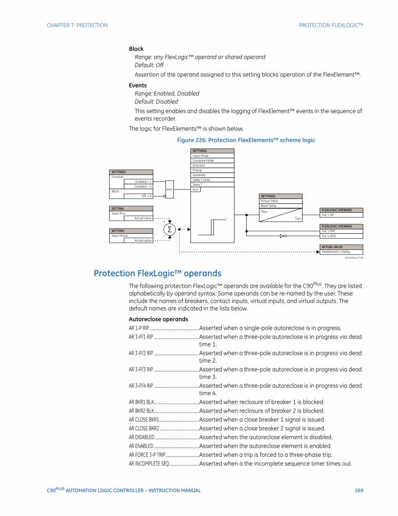
CHAPTER 7: PROTECTION PROTECTION FLEXLOGIC™
C90PLUS AUTOMATION LOGIC CONTROLLER – INSTRUCTION MANUAL 269
BlockRange: any FlexLogic™ operand or shared operandDefault: Off
Assertion of the operand assigned to this setting blocks operation of the FlexElement™.
EventsRange: Enabled, DisabledDefault: Disabled
This setting enables and disables the logging of FlexElement™ events in the sequence of events recorder.
The logic for FlexElements™ is shown below.
Figure 226: Protection FlexElements™ scheme logic
Protection FlexLogic™ operandsThe following protection FlexLogic™ operands are available for the C90Plus. They are listed alphabetically by operand syntax. Some operands can be re-named by the user. These include the names of breakers, contact inputs, virtual inputs, and virtual outputs. The default names are indicated in the lists below.
Autoreclose operandsAR 1-P RIP......................................................Asserted when a single-pole autoreclose is in progress.AR 3-P/1 RIP .................................................Asserted when a three-pole autoreclose is in progress via dead
time 1.AR 3-P/2 RIP .................................................Asserted when a three-pole autoreclose is in progress via dead
time 2.AR 3-P/3 RIP .................................................Asserted when a three-pole autoreclose is in progress via dead
time 3.AR 3-P/4 RIP .................................................Asserted when a three-pole autoreclose is in progress via dead
time 4.AR BKR1 BLK.................................................Asserted when reclosure of breaker 1 is blocked.AR BKR2 BLK.................................................Asserted when reclosure of breaker 2 is blocked.AR CLOSE BKR1...........................................Asserted when a close breaker 1 signal is issued.AR CLOSE BKR2...........................................Asserted when a close breaker 2 signal is issued.AR DISABLED................................................Asserted when the autoreclose element is disabled.AR ENABLED .................................................Asserted when the autoreclose element is enabled.AR FORCE 3-P TRIP ....................................Asserted when a trip is forced to a three-phase trip.AR INCOMPLETE SEQ................................Asserted when a the incomplete sequence timer times out.
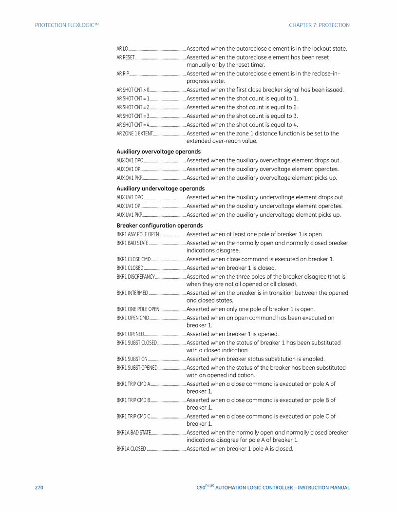
270 C90PLUS AUTOMATION LOGIC CONTROLLER – INSTRUCTION MANUAL
PROTECTION FLEXLOGIC™ CHAPTER 7: PROTECTION
AR LO ............................................................... Asserted when the autoreclose element is in the lockout state.AR RESET........................................................Asserted when the autoreclose element has been reset
manually or by the reset timer.AR RIP ..............................................................Asserted when the autoreclose element is in the reclose-in-
progress state.AR SHOT CNT > 0........................................Asserted when the first close breaker signal has been issued.AR SHOT CNT = 1........................................Asserted when the shot count is equal to 1.AR SHOT CNT = 2........................................Asserted when the shot count is equal to 2.AR SHOT CNT = 3........................................Asserted when the shot count is equal to 3.AR SHOT CNT = 4........................................Asserted when the shot count is equal to 4.AR ZONE 1 EXTENT....................................Asserted when the zone 1 distance function is be set to the
extended over-reach value.
Auxiliary overvoltage operandsAUX OV1 DPO ..............................................Asserted when the auxiliary overvoltage element drops out.AUX OV1 OP.................................................. Asserted when the auxiliary overvoltage element operates.AUX OV1 PKP................................................ Asserted when the auxiliary overvoltage element picks up.
Auxiliary undervoltage operandsAUX UV1 DPO .............................................. Asserted when the auxiliary undervoltage element drops out.AUX UV1 OP.................................................. Asserted when the auxiliary undervoltage element operates.AUX UV1 PKP................................................Asserted when the auxiliary undervoltage element picks up.
Breaker configuration operandsBKR1 ANY POLE OPEN .............................Asserted when at least one pole of breaker 1 is open.BKR1 BAD STATE.........................................Asserted when the normally open and normally closed breaker
indications disagree.BKR1 CLOSE CMD ...................................... Asserted when close command is executed on breaker 1.BKR1 CLOSED ..............................................Asserted when breaker 1 is closed.BKR1 DISCREPANCY..................................Asserted when the three poles of the breaker disagree (that is,
when they are not all opened or all closed).BKR1 INTERMED .........................................Asserted when the breaker is in transition between the opened
and closed states.BKR1 ONE POLE OPEN.............................Asserted when only one pole of breaker 1 is open.BKR1 OPEN CMD ........................................Asserted when an open command has been executed on
breaker 1.BKR1 OPENED..............................................Asserted when breaker 1 is opened.BKR1 SUBST CLOSED................................Asserted when the status of breaker 1 has been substituted
with a closed indication.BKR1 SUBST ON..........................................Asserted when breaker status substitution is enabled.BKR1 SUBST OPENED...............................Asserted when the status of the breaker has been substituted
with an opened indication.BKR1 TRIP CMD A.......................................Asserted when a close command is executed on pole A of
breaker 1.BKR1 TRIP CMD B.......................................Asserted when a close command is executed on pole B of
breaker 1.BKR1 TRIP CMD C.......................................Asserted when a close command is executed on pole C of
breaker 1.BKR1A BAD STATE......................................Asserted when the normally open and normally closed breaker
indications disagree for pole A of breaker 1.BKR1A CLOSED ...........................................Asserted when breaker 1 pole A is closed.
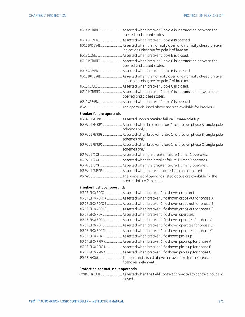
CHAPTER 7: PROTECTION PROTECTION FLEXLOGIC™
C90PLUS AUTOMATION LOGIC CONTROLLER – INSTRUCTION MANUAL 271
BKR1A INTERMED.......................................Asserted when breaker 1 pole A is in transition between the opened and closed states.
BKR1A OPENED...........................................Asserted when breaker 1 pole A is opened.BKR1B BAD STATE ......................................Asserted when the normally open and normally closed breaker
indications disagree for pole B of breaker 1.BKR1B CLOSED............................................Asserted when breaker 1 pole B is closed.BKR1B INTERMED.......................................Asserted when breaker 1 pole B is in transition between the
opened and closed states.BKR1B OPENED...........................................Asserted when breaker 1 pole B is opened.BKR1C BAD STATE ......................................Asserted when the normally open and normally closed breaker
indications disagree for pole C of breaker 1.BKR1C CLOSED............................................Asserted when breaker 1 pole C is closed.BKR1C INTERMED.......................................Asserted when breaker 1 pole C is in transition between the
opened and closed states.BKR1C OPENED...........................................Asserted when breaker 1 pole C is opened.BKR2.................................................................The operands listed above are also available for breaker 2.
Breaker failure operandsBKR FAIL 1 RETRIP......................................Asserted upon a breaker failure 1 three-pole trip.BKR FAIL 1 RETRIPA ...................................Asserted when breaker failure 1 re-trips on phase A (single-pole
schemes only).BKR FAIL 1 RETRIPB...................................Asserted when breaker failure 1 re-trips on phase B (single-pole
schemes only).BKR FAIL 1 RETRIPC...................................Asserted when breaker failure 1 re-trips on phase C (single-pole
schemes only).BKR FAIL 1 T1 OP ........................................Asserted when the breaker failure 1 timer 1 operates.BKR FAIL 1 T2 OP ........................................Asserted when the breaker failure 1 timer 2 operates.BKR FAIL 1 T3 OP ........................................Asserted when the breaker failure 1 timer 3 operates.BKR FAIL 1 TRIP OP ....................................Asserted when breaker failure 1 trip has operated.BKR FAIL 2 .....................................................The same set of operands listed above are available for the
breaker failure 2 element.
Breaker flashover operandsBKR 1 FLSHOVR DPO ................................Asserted when breaker 1 flashover drops out.BKR 1 FLSHOVR DPO A ............................Asserted when breaker 1 flashover drops out for phase A.BKR 1 FLSHOVR DPO B ............................Asserted when breaker 1 flashover drops out for phase B.BKR 1 FLSHOVR DPO C............................Asserted when breaker 1 flashover drops out for phase C.BKR 1 FLSHOVR OP ...................................Asserted when breaker 1 flashover operates.BKR 1 FLSHOVR OP A ...............................Asserted when breaker 1 flashover operates for phase A.BKR 1 FLSHOVR OP B ...............................Asserted when breaker 1 flashover operates for phase B.BKR 1 FLSHOVR OP C ...............................Asserted when breaker 1 flashover operates for phase C.BKR 1 FLSHOVR PKP .................................Asserted when breaker 1 flashover picks up.BKR 1 FLSHOVR PKP A .............................Asserted when breaker 1 flashover picks up for phase A.BKR 1 FLSHOVR PKP B .............................Asserted when breaker 1 flashover picks up for phase B.BKR 1 FLSHOVR PKP C .............................Asserted when breaker 1 flashover picks up for phase C.BKR 2 FLSHOVR...........................................The operands listed above are available for the breaker
flashover 2 element.
Protection contact input operandsCONTACT IP 1 ON .......................................Asserted when the field contact connected to contact input 1 is
closed.
272 C90PLUS AUTOMATION LOGIC CONTROLLER – INSTRUCTION MANUAL
PROTECTION FLEXLOGIC™ CHAPTER 7: PROTECTION
CONTACT IP 1 OFF .....................................Asserted when the field contact connected to contact input 1 is opened.
CONTACT IP 1 TROUBLE OP...................Asserted when there is an internal or external problem with contact input 1.
CONTACT IP 1 TROUBLE DPO................Asserted when there are no problems with contact input 1.CONTACT IP 2 to 40 ...................................The operands listed above are available for the contact inputs 2
through 40.
Digital counter operandsCOUNTER 1 EQL..........................................Asserted when the output of digital counter 1 is equal to the
comparison value.COUNTER 1 HI .............................................Asserted when the output of digital counter 1 is greater than
the comparison value.COUNTER 1 LO ............................................Asserted when the output of digital counter 1 is less than the
comparison value.COUNTER 2 to 8 .......................................... The operands listed above are also available for digital
counters 2 through 8.
FlexMatrix operandsFLXMAT 1 DPO.............................................Asserted when FlexMatrix 1 drops out.FLXMAT 1 OP ................................................Asserted when FlexMatrix 1 operates.FLXMAT 1 PKP..............................................Asserted when FlexMatrix 1 picks up.FLXMAT 2 to 8 .............................................. The operands listed above are also available for FlexMatrix
elements 2 through 8.
FlexElement™ operandsFXE 1 DPO......................................................Asserted when protection FlexElement™ 1 drops out.FXE 1 OP.........................................................Asserted when protection FlexElement™ 1 operates.FXE 1 PKP.......................................................Asserted when protection FlexElement™ 1 picks up.FXE 2 to 8....................................................... The operands listed above are also available for protection
FlexElements™ 2 through 8.
Ground instantaneous overcurrent operandsGROUND IOC1 DPO ..................................Asserted when ground instantaneous overcurrent 1 drops out.GROUND IOC1 OP......................................Asserted when ground instantaneous overcurrent 1 operates.GROUND IOC1 PKP....................................Asserted when ground instantaneous overcurrent 1 picks up.GROUND IOC2 to 12 ................................. The operands listed above are also available for ground
instantaneous overcurrent elements 2 through 12.
Ground time overcurrent operandsGROUND TOC1 DPO .................................Asserted when ground time overcurrent 1 drops out.GROUND TOC1 OP.....................................Asserted when ground time overcurrent 1 operates.GROUND TOC1 PKP...................................Asserted when ground time overcurrent 1 picks up.GROUND TOC2 to 6 ...................................The operands listed above are also available for ground time
overcurrent elements 2 through 6.
Non-volatile latch operandsLATCH 1 OFF.................................................Asserted when non-volatile latch 1 is off (logic 0).LATCH 1 ON ..................................................Asserted when non-volatile latch 1 is on (logic 1).LATCH 2 to 16 .............................................. The operands listed above are also available for non-volatile
latches 2 to 16.
Neutral directional overcurrent operandsNTRL DIR OC1 FWD...................................Asserted when the neutral directional overcurrent 1 element
forward mode operates.
CHAPTER 7: PROTECTION PROTECTION FLEXLOGIC™
C90PLUS AUTOMATION LOGIC CONTROLLER – INSTRUCTION MANUAL 273
NTRL DIR OC1 REV.....................................Asserted when the neutral directional overcurrent 1 element reverse mode operates.
NTRL DIR OC2 FWD...................................Asserted when the neutral directional overcurrent 2 element forward mode operates.
NTRL DIR OC2 REV.....................................Asserted when the neutral directional overcurrent 2 element reverse mode operates.
Negative-sequence instantaneous overcurrent operandsNEG SEQ IOC1 DPO ...................................Asserted when the negative-sequence instantaneous
overcurrent 1 element drops out.NEG SEQ IOC1 OP.......................................Asserted when the negative-sequence instantaneous
overcurrent 1 element operates.NEG SEQ IOC1 PKP ....................................Asserted when the negative-sequence instantaneous
overcurrent 1 element picks up.NEG SEQ IOC2 ..............................................The operands listed above are also available for negative-
sequence instantaneous overcurrent 2.
Negative-sequence overvoltage operandsNEG SEQ OV DPO .......................................Asserted when the negative-sequence overvoltage element
drops out.NEG SEQ OV OP...........................................Asserted when the negative-sequence overvoltage element
operates.NEG SEQ OV PKP ........................................Asserted when the negative-sequence overvoltage element
has picks up.
Negative-sequence time overcurrent operandsNEG SEQ TOC1 DPO ..................................Asserted when the negative-sequence time overcurrent 1
element drops out.NEG SEQ TOC1 OP .....................................Asserted when the negative-sequence time overcurrent 1
element operates.NEG SEQ TOC1 PKP ...................................Asserted when the negative-sequence time overcurrent 1
element picks up.NEG SEQ TOC2 .............................................The operands listed above are also available for negative-
sequence time overcurrent 2.
Neutral instantaneous overcurrent operandsNEUTRAL IOC1 DPO ..................................Asserted when the neutral instantaneous overcurrent 1
element drops out.NEUTRAL IOC1 OP......................................Asserted when the neutral instantaneous overcurrent 1
element operates.NEUTRAL IOC1 PKP....................................Asserted when the neutral instantaneous overcurrent 1
element picks up.NEUTRAL IOC2 to 12 .................................The operands listed above are also available for neutral
instantaneous overcurrent 2 through 12.
Neutral overvoltage operandsNEUTRAL OV1 DPO....................................Asserted when the neutral overvoltage 1 element drops out.NEUTRAL OV1 OP .......................................Asserted when the neutral overvoltage 1 element operates.NEUTRAL OV1 PKP.....................................Asserted when the neutral overvoltage 1 element picks up.NEUTRAL OV2 to 3 .....................................The operands listed above are also available for neutral
overvoltage 2 and 3.
Neutral time overcurrent operandsNEUTRAL TOC1 DPO .................................Asserted when the neutral time overcurrent 1 element drops
out.
274 C90PLUS AUTOMATION LOGIC CONTROLLER – INSTRUCTION MANUAL
PROTECTION FLEXLOGIC™ CHAPTER 7: PROTECTION
NEUTRAL TOC1 OP ....................................Asserted when the neutral time overcurrent 1 element operates.
NEUTRAL TOC1 PKP ..................................Asserted when the neutral time overcurrent 1 element picks up.NEUTRAL TOC 2 to 6 ................................. The operands listed above are also available for neutral time
overcurrent 2 through 6.
Neutral directional overcurrent operandsNTRL DIR OC1 FWD...................................Asserted when the neutral directional overcurrent 1 element
forward mode operates.NTRL DIR OC1 REV.....................................Asserted when the neutral directional overcurrent 1 element
reverse mode operates.NTRL DIR OC2 FWD...................................Asserted when the neutral directional overcurrent 2 element
forward mode operates.NTRL DIR OC2 REV.....................................Asserted when the neutral directional overcurrent 2 element
reverse mode operates.
Phase directional overcurrent operandsPH DIR1 BLK .................................................Asserted when the phase directional overcurrent 1 element is
blocked.PH DIR1 BLK A .............................................Asserted when the phase directional overcurrent 1 element is
blocked in phase A.PH DIR1 BLK B .............................................Asserted when the phase directional overcurrent 1 element is
blocked in phase B.PH DIR1 BLK C .............................................Asserted when the phase directional overcurrent 1 element is
blocked in phase C.PH DIR 2 ......................................................... Same set of operands as shown above for the phase directional
overcurrent 2 element.
Phase instantaneous overcurrent operandsPHASE IOC1 DPO........................................Asserted when at least one phase of the phase instantaneous
overcurrent 1 element drops out.PHASE IOC1 DPO A....................................Asserted when phase A of the phase instantaneous
overcurrent 1 element drops out.PHASE IOC1 DPO B....................................Asserted when phase B of the phase instantaneous
overcurrent 1 element drops out.PHASE IOC1 DPO C....................................Asserted when phase C of the phase instantaneous
overcurrent 1 element drops out.PHASE IOC1 OP ........................................... Asserted when at least one phase of the phase instantaneous
overcurrent 1 element operates.PHASE IOC1 OP A .......................................Asserted when phase A of the phase instantaneous
overcurrent 1 element operates.PHASE IOC1 OP B .......................................Asserted when phase B of the phase instantaneous
overcurrent 1 element operates.PHASE IOC1 OP C.......................................Asserted when phase C of the phase instantaneous
overcurrent 1 element operates.PHASE IOC1 PKP......................................... Asserted when at least one phase of the phase instantaneous
overcurrent 1 element picks up.PHASE IOC1 PKP A.....................................Asserted when phase A of the phase instantaneous
overcurrent 1 element picks up.PHASE IOC1 PKP B.....................................Asserted when phase B of the phase instantaneous
overcurrent 1 element picks up.PHASE IOC1 PKP C.....................................Asserted when phase C of the phase instantaneous
overcurrent 1 element picks up.
CHAPTER 7: PROTECTION PROTECTION FLEXLOGIC™
C90PLUS AUTOMATION LOGIC CONTROLLER – INSTRUCTION MANUAL 275
PHASE IOC2 to 12.......................................Same set of operands as shown above for the phase instantaneous overcurrent elements 2 through 12.
Phase overvoltage operandsPHASE OV1 DPO .........................................Asserted when at least one phase of the phase overvoltage 1
element drops out.PHASE OV1 DPO A .....................................Asserted when phase A of the phase overvoltage 1 element
drops out.PHASE OV1 DPO B .....................................Asserted when phase B of the phase overvoltage 1 element
drops out.PHASE OV1 DPO C .....................................Asserted when phase C of the phase overvoltage 1 element
drops out.PHASE OV1 OP.............................................Asserted when at least one phase of the phase overvoltage 1
element operates.PHASE OV1 OP A.........................................Asserted when phase A of the phase overvoltage 1 element
operates.PHASE OV1 OP B.........................................Asserted when phase B of the phase overvoltage 1 element
operates.PHASE OV1 OP C.........................................Asserted when phase C of the phase overvoltage 1 element
operates.PHASE OV1 PKP...........................................Asserted when at least one phase of the phase overvoltage 1
element picks up.PHASE OV1 PKP A ......................................Asserted when phase A of the phase overvoltage 1 element
picks up.PHASE OV1 PKP B ......................................Asserted when phase B of the phase overvoltage 1 element
picks up.PHASE OV1 PKP C ......................................Asserted when phase C of the phase overvoltage 1 element
picks up.PHASE OV2 ....................................................Same set of operands as shown above for the phase
overvoltage 2 element.
Phase time overcurrent operandsPHASE TOC1 DPO.......................................Asserted when at least one phase of the phase time
overcurrent 1 element drops out.PHASE TOC1 DPO A...................................Asserted when phase A of the phase time overcurrent 1
element drops out.PHASE TOC1 DPO B...................................Asserted when phase B of the phase time overcurrent 1
element drops out.PHASE TOC1 DPO C...................................Asserted when phase C of the phase time overcurrent 1
element drops out.PHASE TOC1 OP ..........................................Asserted when at least one phase of the phase time
overcurrent 1 element operates.PHASE TOC1 OP A ......................................Asserted when phase A of the phase time overcurrent 1
element operates.PHASE TOC1 OP B ......................................Asserted when phase B of the phase time overcurrent 1
element operates.PHASE TOC1 OP C ......................................Asserted when phase C of the phase time overcurrent 1
element operates.PHASE TOC1 PKP ........................................Asserted when at least one phase of the phase time
overcurrent 1 element picks up.PHASE TOC1 PKP A ....................................Asserted when phase A of the phase time overcurrent 1
element picks up.
276 C90PLUS AUTOMATION LOGIC CONTROLLER – INSTRUCTION MANUAL
PROTECTION FLEXLOGIC™ CHAPTER 7: PROTECTION
PHASE TOC1 PKP B....................................Asserted when phase B of the phase time overcurrent 1 element picks up.
PHASE TOC1 PKP C....................................Asserted when phase C of the phase time overcurrent 1 element picks up.
PHASE TOC2 to 6 ........................................Same set of operands as shown above for the phase time overcurrent elements 2 through 6.
Phase overvoltage operandsPHASE OV1 DPO .........................................Asserted when at least one phase of the phase overvoltage 1
element drops out.PHASE OV1 DPO A .....................................Asserted when phase A of the phase overvoltage 1 element
drops out.PHASE OV1 DPO B .....................................Asserted when phase B of the phase overvoltage 1 element
drops out.PHASE OV1 DPO C.....................................Asserted when phase C of the phase overvoltage 1 element
drops out.PHASE OV1 OP ............................................Asserted when at least one phase of the phase overvoltage 1
element operates.PHASE OV1 OP A ........................................Asserted when phase A of the phase overvoltage 1 element
operates.PHASE OV1 OP B ........................................Asserted when phase B of the phase overvoltage 1 element
operates.PHASE OV1 OP C ........................................Asserted when phase C of the phase overvoltage 1 element
operates.PHASE OV1 PKP ..........................................Asserted when at least one phase of the phase overvoltage 1
element picks up.PHASE OV1 PKP A ......................................Asserted when phase A of the phase overvoltage 1 element
picks up.PHASE OV1 PKP B ......................................Asserted when phase B of the phase overvoltage 1 element
picks up.PHASE OV1 PKP C ......................................Asserted when phase C of the phase overvoltage 1 element
picks up.PHASE OV2 .................................................... Same set of operands as shown above for the phase
overvoltage 2 element.
Phase undervoltage operandsPHASE UV1 DPO ......................................... Asserted when at least one phase of the phase undervoltage 1
element drops out.PHASE UV1 DPO A .....................................Asserted when phase A of the phase undervoltage 1 element
drops out.PHASE UV1 DPO B .....................................Asserted when phase B of the phase undervoltage 1 element
drops out.PHASE UV1 DPO C .....................................Asserted when phase C of the phase undervoltage 1 element
drops out.PHASE UV1 OP............................................. Asserted when at least one phase of the phase undervoltage 1
element operates.PHASE UV1 OP A ........................................Asserted when phase A of the phase undervoltage 1 element
operates.PHASE UV1 OP B ........................................Asserted when phase B of the phase undervoltage 1 element
operates.PHASE UV1 OP C ........................................Asserted when phase C of the phase undervoltage 1 element
operates.
CHAPTER 7: PROTECTION PROTECTION FLEXLOGIC™
C90PLUS AUTOMATION LOGIC CONTROLLER – INSTRUCTION MANUAL 277
PHASE UV1 PKP...........................................Asserted when at least one phase of the phase undervoltage 1 element picks up.
PHASE UV1 PKP A.......................................Asserted when phase A of the phase undervoltage 1 element picks up.
PHASE UV1 PKP B.......................................Asserted when phase B of the phase undervoltage 1 element picks up.
PHASE UV1 PKP C ......................................Asserted when phase C of the phase undervoltage 1 element picks up.
PHASE UV2 ....................................................Same set of operands as shown above for the phase undervoltage 2 element.
Setting group operandsSETTING GROUP ACT 1 ............................Asserted when setting group 1 is active.SETTING GROUP ACT 2 ............................Asserted when setting group 2 is active.SETTING GROUP ACT 3 ............................Asserted when setting group 3 is active.SETTING GROUP ACT 4 ............................Asserted when setting group 4 is active.SETTING GROUP ACT 5 ............................Asserted when setting group 5 is active.SETTING GROUP ACT 6 ............................Asserted when setting group 6 is active.
Disturbance detector operandsSRC1 50DD OP.............................................Asserted when the disturbance detector for source 1 operates.SRC2 50DD OP.............................................Asserted when the disturbance detector for source 2 operates.SRC3 50DD OP.............................................Asserted when the disturbance detector for source 3 operates.
Voltage transformer fuse failure (VTFF) operandsSRC1 VTFF DPO...........................................Asserted when the VT fuse failure detector for source 1 drops
out.SRC1 VTFF OP ..............................................Asserted when the VT fuse failure detector for source 1
operates.SRC1 VTFF VOL LOSS................................Asserted when the VT fuse failure detector for source 1 loses
voltage signals (V2 is less than 15% and V1 is less than 5% of nominal).
SRC2 to SRC3... ............................................The set of operands shown above are available VT fuse failure elements for sources 2 through 3.

278 C90PLUS AUTOMATION LOGIC CONTROLLER – INSTRUCTION MANUAL
PROTECTION FLEXLOGIC™ CHAPTER 7: PROTECTION
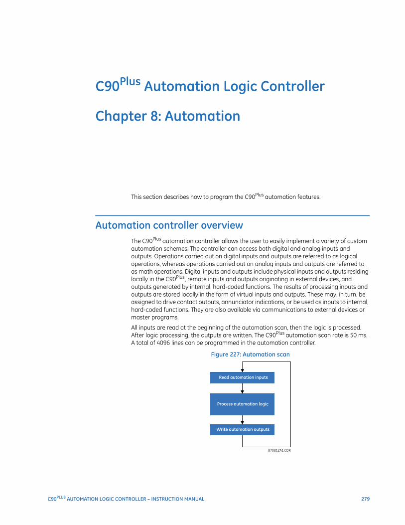
C90PLUS AUTOMATION LOGIC CONTROLLER – INSTRUCTION MANUAL 279
C90Plus Automation Logic Controller
Chapter 8: Automation
Automation
This section describes how to program the C90Plus automation features.
Automation controller overviewThe C90Plus automation controller allows the user to easily implement a variety of custom automation schemes. The controller can access both digital and analog inputs and outputs. Operations carried out on digital inputs and outputs are referred to as logical operations, whereas operations carried out on analog inputs and outputs are referred to as math operations. Digital inputs and outputs include physical inputs and outputs residing locally in the C90Plus, remote inputs and outputs originating in external devices, and outputs generated by internal, hard-coded functions. The results of processing inputs and outputs are stored locally in the form of virtual inputs and outputs. These may, in turn, be assigned to drive contact outputs, annunciator indications, or be used as inputs to internal, hard-coded functions. They are also available via communications to external devices or master programs.
All inputs are read at the beginning of the automation scan, then the logic is processed. After logic processing, the outputs are written. The C90Plus automation scan rate is 50 ms. A total of 4096 lines can be programmed in the automation controller.
Figure 227: Automation scan
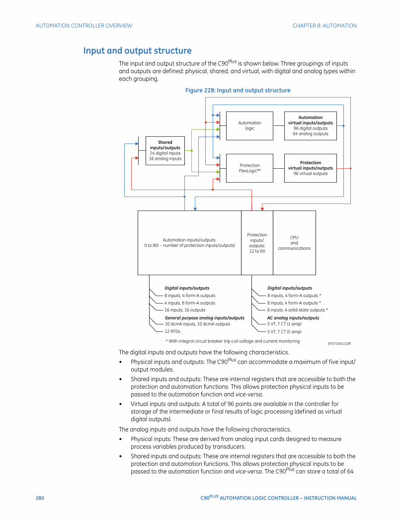
280 C90PLUS AUTOMATION LOGIC CONTROLLER – INSTRUCTION MANUAL
AUTOMATION CONTROLLER OVERVIEW CHAPTER 8: AUTOMATION
Input and output structureThe input and output structure of the C90Plus is shown below. Three groupings of inputs and outputs are defined: physical, shared, and virtual, with digital and analog types within each grouping.
Figure 228: Input and output structure
The digital inputs and outputs have the following characteristics.
• Physical inputs and outputs: The C90Plus can accommodate a maximum of five input/output modules.
• Shared inputs and outputs: These are internal registers that are accessible to both the protection and automation functions. This allows protection physical inputs to be passed to the automation function and vice-versa.
• Virtual inputs and outputs: A total of 96 points are available in the controller for storage of the intermediate or final results of logic processing (defined as virtual digital outputs).
The analog inputs and outputs have the following characteristics.
• Physical inputs: These are derived from analog input cards designed to measure process variables produced by transducers.
• Shared inputs and outputs: These are internal registers that are accessible to both the protection and automation functions. This allows protection physical inputs to be passed to the automation function and vice-versa. The C90Plus can store a total of 64
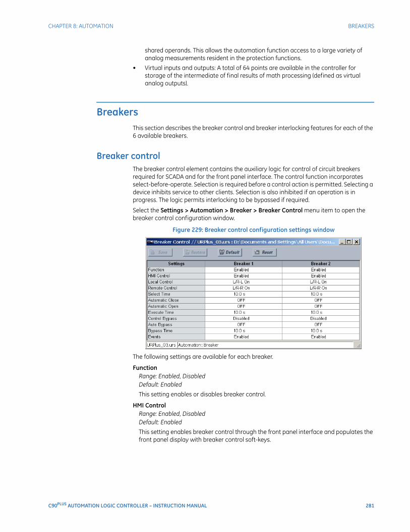
CHAPTER 8: AUTOMATION BREAKERS
C90PLUS AUTOMATION LOGIC CONTROLLER – INSTRUCTION MANUAL 281
shared operands. This allows the automation function access to a large variety of analog measurements resident in the protection functions.
• Virtual inputs and outputs: A total of 64 points are available in the controller for storage of the intermediate of final results of math processing (defined as virtual analog outputs).
BreakersThis section describes the breaker control and breaker interlocking features for each of the 6 available breakers.
Breaker controlThe breaker control element contains the auxiliary logic for control of circuit breakers required for SCADA and for the front panel interface. The control function incorporates select-before-operate. Selection is required before a control action is permitted. Selecting a device inhibits service to other clients. Selection is also inhibited if an operation is in progress. The logic permits interlocking to be bypassed if required.
Select the Settings > Automation > Breaker > Breaker Control menu item to open the breaker control configuration window.
Figure 229: Breaker control configuration settings window
The following settings are available for each breaker.
FunctionRange: Enabled, DisabledDefault: Enabled
This setting enables or disables breaker control.
HMI ControlRange: Enabled, DisabledDefault: Enabled
This setting enables breaker control through the front panel interface and populates the front panel display with breaker control soft-keys.
282 C90PLUS AUTOMATION LOGIC CONTROLLER – INSTRUCTION MANUAL
BREAKERS CHAPTER 8: AUTOMATION
Local ControlRange: any automation logic operand or shared operandDefault: L/R-L On
When the operand assigned to this setting is asserted, control is enabled from the front panel interface. This setting is normally assigned to the local status of a local/remote switch. If continuous local control is required, this setting may be programmed as “On”.
Remote ControlRange: any automation logic operand or shared operandDefault: L/R-R On
When the operand assigned to this setting is asserted, control is enabled from SCADA. This setting is normally assigned to the remote status of a local/remote switch. If continuous remote control is required, this setting may be programmed as “On”.
Select TimeRange: 0.00 to 30.00 seconds in steps of 0.01Default: 10.00 seconds
This setting determines the maximum permissible time from selection of the breaker and a control action.
Automatic CloseRange: any automation logic operand or shared operandDefault: OFF
This setting is used to close the device from an automatic control scheme.
Automatic OpenRange: any automation logic operand or shared operandDefault: OFF
This setting is used to open the device from an automatic control scheme.
Execute TimeRange: 0.0 to 10.0 seconds in steps of 0.1Default: 10.0 seconds
This setting determines the duration of the open and close commands used to control the breaker.
Control BypassRange: Enabled, DisabledDefault: Disabled
When enabled, this setting allows the interlocking to be bypassed from local or remote control.
FASTPATH: Non-interlocked control can result in equipment damage.
Automation BypassRange: any automation logic operand or shared operandDefault: OFF
When the operand assigned to this setting is asserted, interlocking is bypassed.FASTPATH: Non-interlocked control can result in equipment damage.
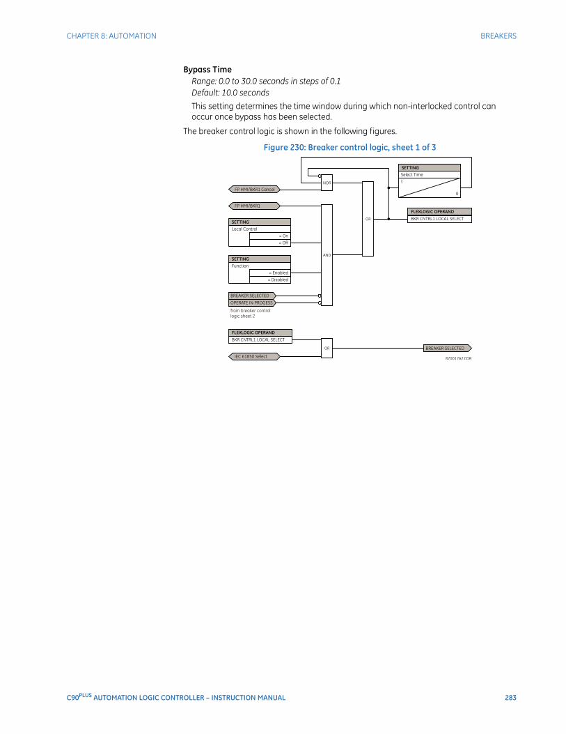
CHAPTER 8: AUTOMATION BREAKERS
C90PLUS AUTOMATION LOGIC CONTROLLER – INSTRUCTION MANUAL 283
Bypass TimeRange: 0.0 to 30.0 seconds in steps of 0.1Default: 10.0 seconds
This setting determines the time window during which non-interlocked control can occur once bypass has been selected.
The breaker control logic is shown in the following figures.
Figure 230: Breaker control logic, sheet 1 of 3
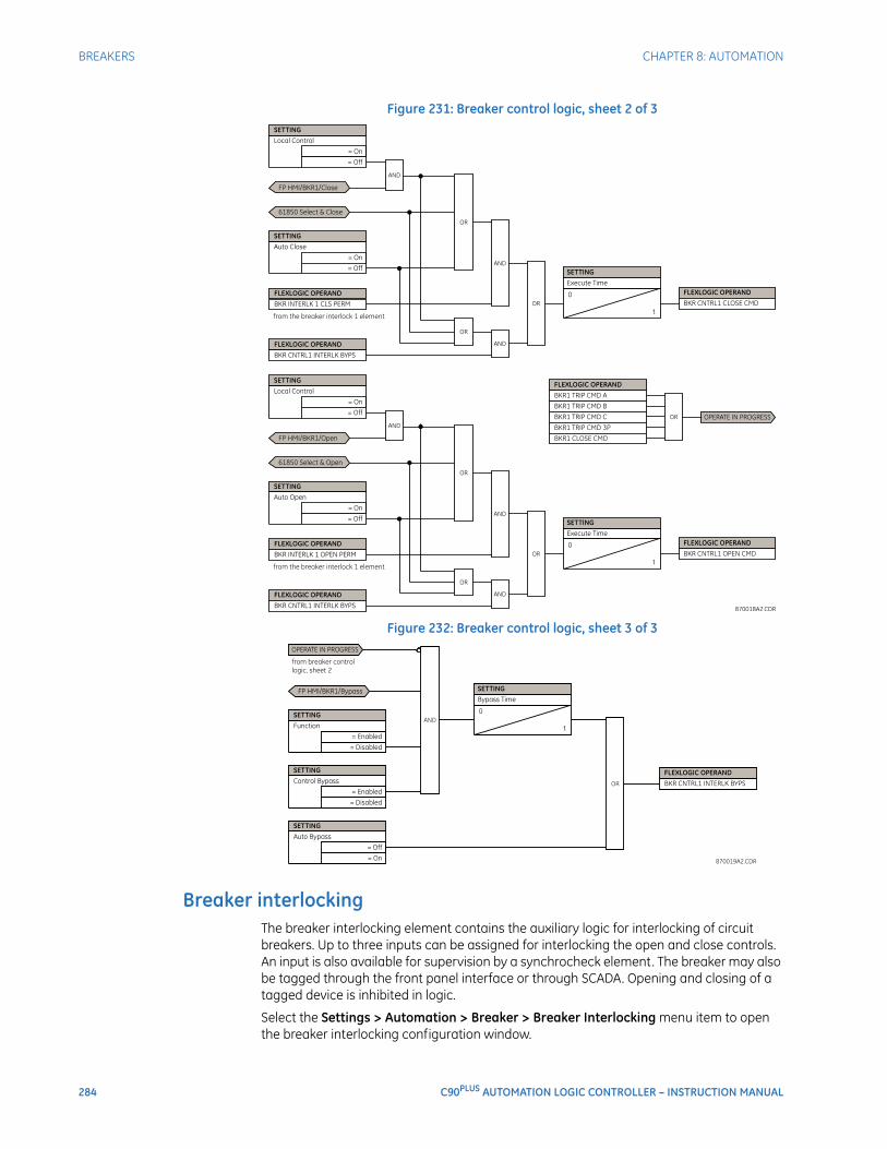
284 C90PLUS AUTOMATION LOGIC CONTROLLER – INSTRUCTION MANUAL
BREAKERS CHAPTER 8: AUTOMATION
Figure 231: Breaker control logic, sheet 2 of 3
Figure 232: Breaker control logic, sheet 3 of 3
Breaker interlockingThe breaker interlocking element contains the auxiliary logic for interlocking of circuit breakers. Up to three inputs can be assigned for interlocking the open and close controls. An input is also available for supervision by a synchrocheck element. The breaker may also be tagged through the front panel interface or through SCADA. Opening and closing of a tagged device is inhibited in logic.
Select the Settings > Automation > Breaker > Breaker Interlocking menu item to open the breaker interlocking configuration window.
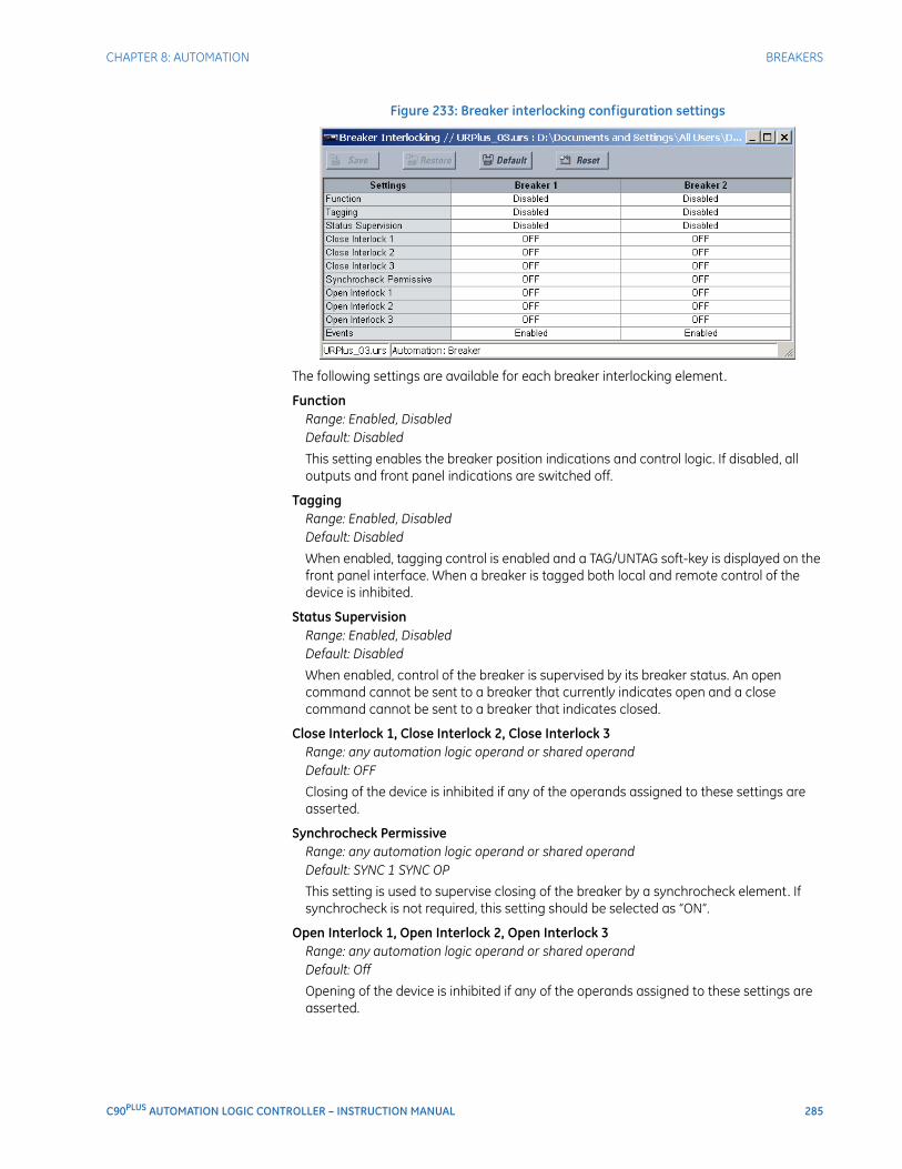
CHAPTER 8: AUTOMATION BREAKERS
C90PLUS AUTOMATION LOGIC CONTROLLER – INSTRUCTION MANUAL 285
Figure 233: Breaker interlocking configuration settings
The following settings are available for each breaker interlocking element.
FunctionRange: Enabled, DisabledDefault: Disabled
This setting enables the breaker position indications and control logic. If disabled, all outputs and front panel indications are switched off.
TaggingRange: Enabled, DisabledDefault: Disabled
When enabled, tagging control is enabled and a TAG/UNTAG soft-key is displayed on the front panel interface. When a breaker is tagged both local and remote control of the device is inhibited.
Status SupervisionRange: Enabled, DisabledDefault: Disabled
When enabled, control of the breaker is supervised by its breaker status. An open command cannot be sent to a breaker that currently indicates open and a close command cannot be sent to a breaker that indicates closed.
Close Interlock 1, Close Interlock 2, Close Interlock 3Range: any automation logic operand or shared operandDefault: OFF
Closing of the device is inhibited if any of the operands assigned to these settings are asserted.
Synchrocheck PermissiveRange: any automation logic operand or shared operandDefault: SYNC 1 SYNC OP
This setting is used to supervise closing of the breaker by a synchrocheck element. If synchrocheck is not required, this setting should be selected as “ON”.
Open Interlock 1, Open Interlock 2, Open Interlock 3Range: any automation logic operand or shared operandDefault: Off
Opening of the device is inhibited if any of the operands assigned to these settings are asserted.
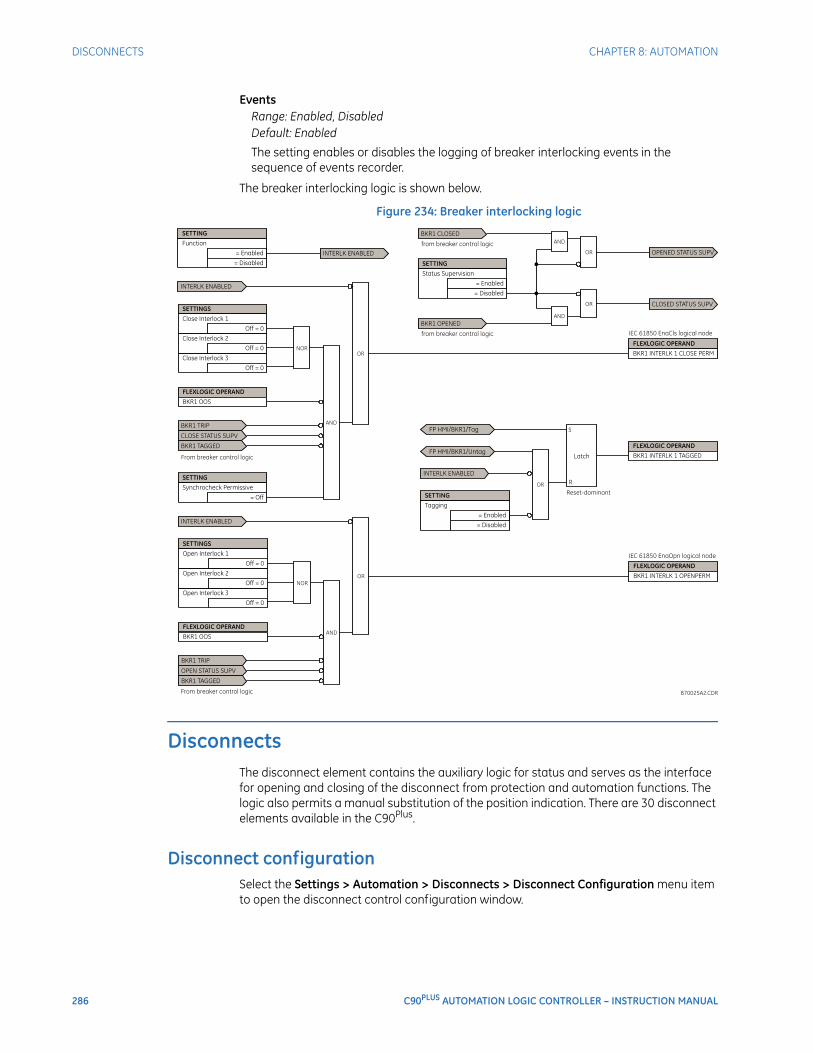
286 C90PLUS AUTOMATION LOGIC CONTROLLER – INSTRUCTION MANUAL
DISCONNECTS CHAPTER 8: AUTOMATION
EventsRange: Enabled, DisabledDefault: Enabled
The setting enables or disables the logging of breaker interlocking events in the sequence of events recorder.
The breaker interlocking logic is shown below.
Figure 234: Breaker interlocking logic
DisconnectsThe disconnect element contains the auxiliary logic for status and serves as the interface for opening and closing of the disconnect from protection and automation functions. The logic also permits a manual substitution of the position indication. There are 30 disconnect elements available in the C90Plus.
Disconnect configurationSelect the Settings > Automation > Disconnects > Disconnect Configuration menu item to open the disconnect control configuration window.
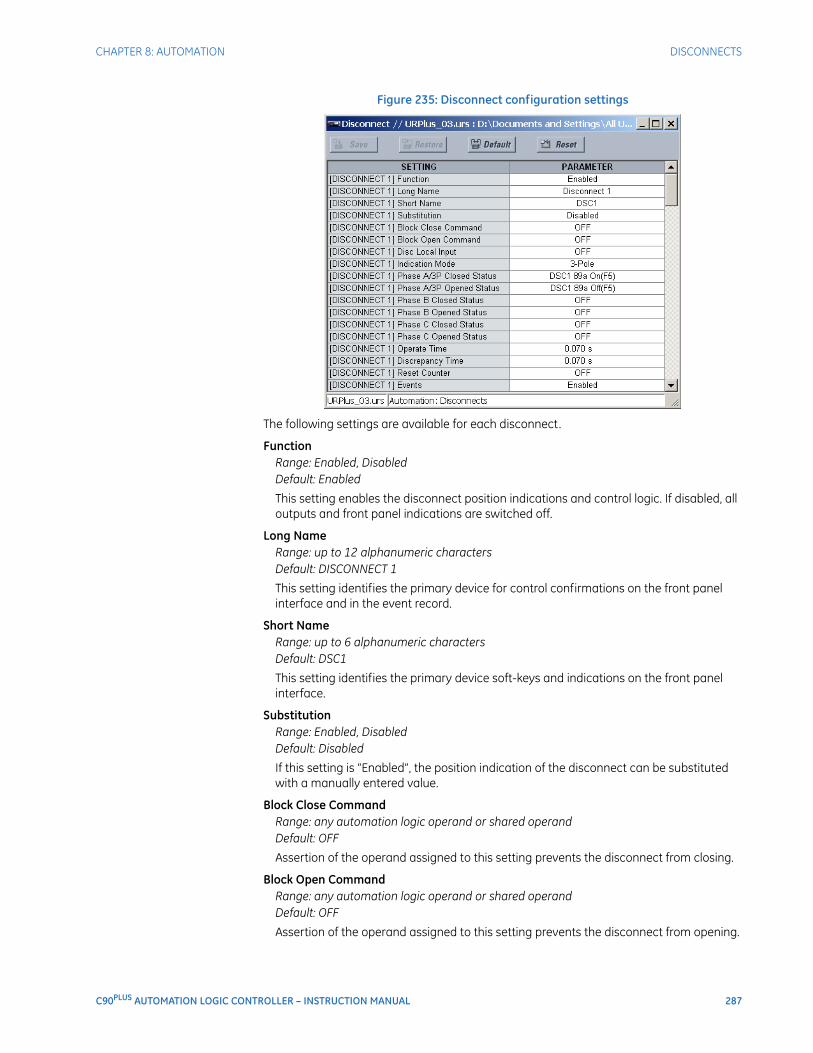
CHAPTER 8: AUTOMATION DISCONNECTS
C90PLUS AUTOMATION LOGIC CONTROLLER – INSTRUCTION MANUAL 287
Figure 235: Disconnect configuration settings
The following settings are available for each disconnect.
FunctionRange: Enabled, DisabledDefault: Enabled
This setting enables the disconnect position indications and control logic. If disabled, all outputs and front panel indications are switched off.
Long NameRange: up to 12 alphanumeric charactersDefault: DISCONNECT 1
This setting identifies the primary device for control confirmations on the front panel interface and in the event record.
Short NameRange: up to 6 alphanumeric charactersDefault: DSC1
This setting identifies the primary device soft-keys and indications on the front panel interface.
SubstitutionRange: Enabled, DisabledDefault: Disabled
If this setting is “Enabled”, the position indication of the disconnect can be substituted with a manually entered value.
Block Close CommandRange: any automation logic operand or shared operandDefault: OFF
Assertion of the operand assigned to this setting prevents the disconnect from closing.
Block Open CommandRange: any automation logic operand or shared operandDefault: OFF
Assertion of the operand assigned to this setting prevents the disconnect from opening.
288 C90PLUS AUTOMATION LOGIC CONTROLLER – INSTRUCTION MANUAL
DISCONNECTS CHAPTER 8: AUTOMATION
Disconnect Local InputRange: any automation logic operand or shared operandDefault: OFF
Closing or opening of the disconnect through the disconnect interlock element is inhibited if the operand assigned to this setting is asserted.
Indication ModeRange: 3-Pole, 1-PoleDefault: 3-Pole
If the “3-Pole” value is selected, the disconnect indications are derived from a single status input (or pair of status inputs). If the “1-Pole” value is selected, the disconnect indications are derived from three status inputs (or pairs of status inputs).
Phase A/3P Closed StatusRange: any automation logic operand or shared operandDefault: Off
The operand assigned to this setting is used to derive the three-pole or phase A circuit disconnect position indication from a normally-opened (52a) status input.
Phase A/3P Opened StatusRange: any automation logic operand or shared operandDefault: DSC2 89a On(K10)
The operand assigned to this setting is used to derive the three-pole or phase A circuit disconnect position indication from a normally-closed (52b) status input. If unavailable, the closed status input can be inverted to provide this signal.
Phase B Closed StatusRange: any automation logic operand or shared operandDefault: DSC2 89a Off(K10)
The operand assigned to this setting is used to derive the phase B disconnect position indication from a normally-opened (52a) status input. This setting is not required if the Indication Mode is “1-Pole”.
Phase B Opened StatusRange: any automation logic operand or shared operandDefault: Off
The operand assigned to this setting is used to derive the phase B disconnect position indication from a normally-closed (52b) status input. If unavailable, the closed status input can be inverted to provide this signal. This setting is not required if the Indication Mode is “1-Pole”.
Phase C Opened StatusRange: any automation logic operand or shared operandDefault: Off
The operand assigned to this setting is used to derive the phase C disconnect position indication from a normally-opened (52a) status input. This setting is not required if the Indication Mode is “1-Pole”.
Phase C Closed StatusRange: any automation logic operand or shared operandDefault: Off
The operand assigned to this setting is used to derive the phase C disconnect position indication from a normally-closed (52b) status input. If unavailable, the closed status input can be inverted to provide this signal. This setting is not required if the Indication Mode is “1-Pole”.
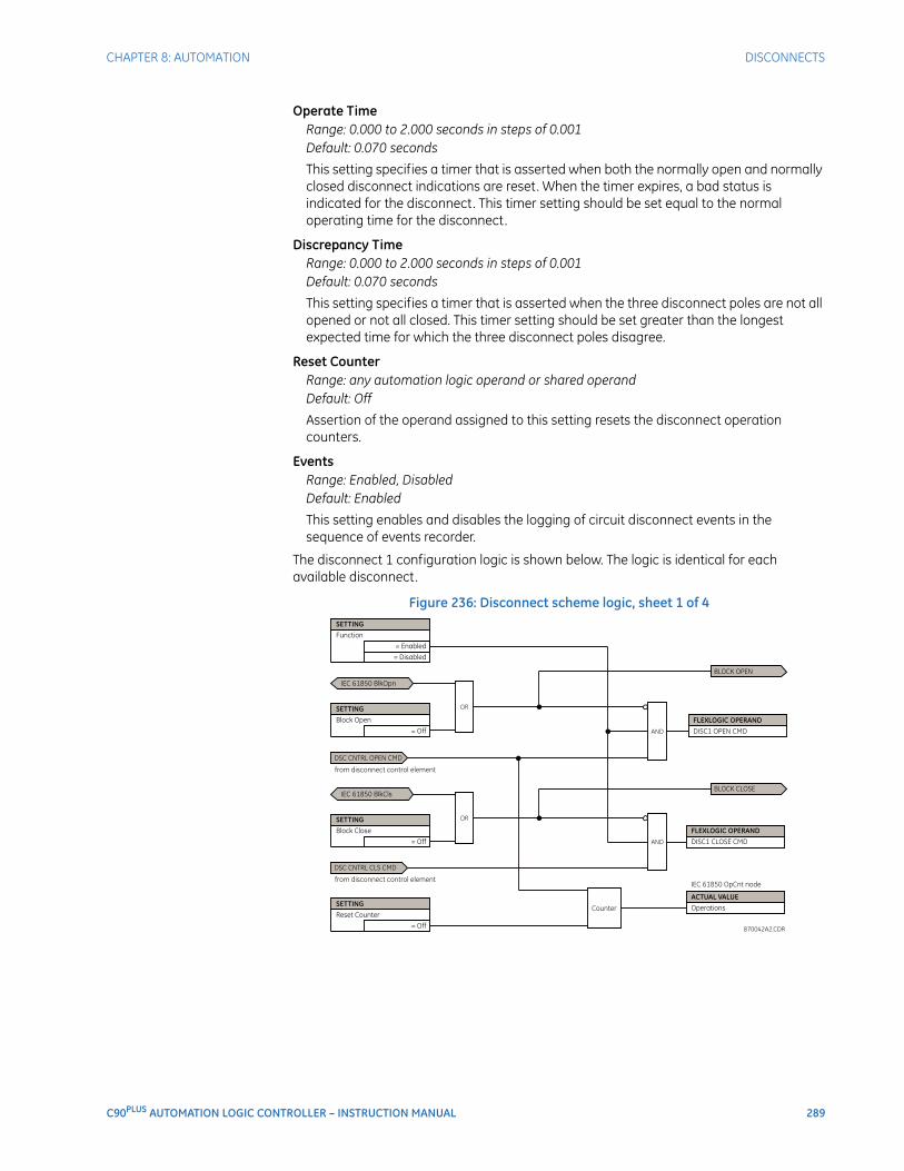
CHAPTER 8: AUTOMATION DISCONNECTS
C90PLUS AUTOMATION LOGIC CONTROLLER – INSTRUCTION MANUAL 289
Operate TimeRange: 0.000 to 2.000 seconds in steps of 0.001Default: 0.070 seconds
This setting specifies a timer that is asserted when both the normally open and normally closed disconnect indications are reset. When the timer expires, a bad status is indicated for the disconnect. This timer setting should be set equal to the normal operating time for the disconnect.
Discrepancy TimeRange: 0.000 to 2.000 seconds in steps of 0.001Default: 0.070 seconds
This setting specifies a timer that is asserted when the three disconnect poles are not all opened or not all closed. This timer setting should be set greater than the longest expected time for which the three disconnect poles disagree.
Reset CounterRange: any automation logic operand or shared operandDefault: Off
Assertion of the operand assigned to this setting resets the disconnect operation counters.
EventsRange: Enabled, DisabledDefault: Enabled
This setting enables and disables the logging of circuit disconnect events in the sequence of events recorder.
The disconnect 1 configuration logic is shown below. The logic is identical for each available disconnect.
Figure 236: Disconnect scheme logic, sheet 1 of 4
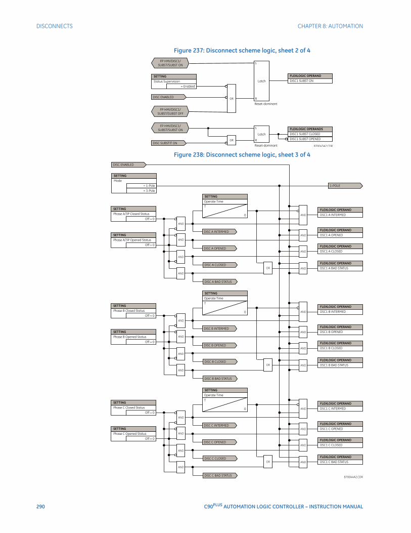
290 C90PLUS AUTOMATION LOGIC CONTROLLER – INSTRUCTION MANUAL
DISCONNECTS CHAPTER 8: AUTOMATION
Figure 237: Disconnect scheme logic, sheet 2 of 4
Figure 238: Disconnect scheme logic, sheet 3 of 4
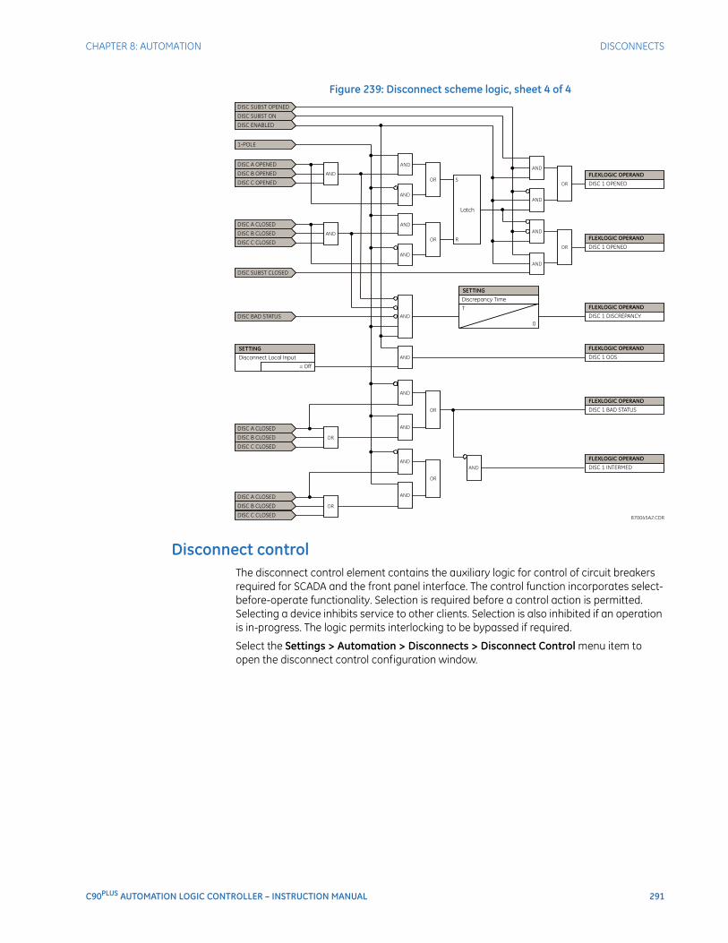
CHAPTER 8: AUTOMATION DISCONNECTS
C90PLUS AUTOMATION LOGIC CONTROLLER – INSTRUCTION MANUAL 291
Figure 239: Disconnect scheme logic, sheet 4 of 4
Disconnect controlThe disconnect control element contains the auxiliary logic for control of circuit breakers required for SCADA and the front panel interface. The control function incorporates select-before-operate functionality. Selection is required before a control action is permitted. Selecting a device inhibits service to other clients. Selection is also inhibited if an operation is in-progress. The logic permits interlocking to be bypassed if required.
Select the Settings > Automation > Disconnects > Disconnect Control menu item to open the disconnect control configuration window.
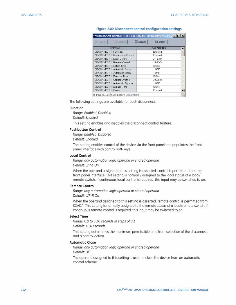
292 C90PLUS AUTOMATION LOGIC CONTROLLER – INSTRUCTION MANUAL
DISCONNECTS CHAPTER 8: AUTOMATION
Figure 240: Disconnect control configuration settings
The following settings are available for each disconnect.
FunctionRange: Enabled, DisabledDefault: Enabled
This setting enables and disables the disconnect control feature.
Pushbutton ControlRange: Enabled, DisabledDefault: Enabled
This setting enables control of the device via the front panel and populates the front panel interface with control soft-keys.
Local ControlRange: any automation logic operand or shared operandDefault: L/R-L On
When the operand assigned to this setting is asserted, control is permitted from the front panel interface. This setting is normally assigned to the local status of a local/remote switch. If continuous local control is required, this input may be switched to on.
Remote ControlRange: any automation logic operand or shared operandDefault: L/R-R On
When the operand assigned to this setting is asserted, remote control is permitted from SCADA. This setting is normally assigned to the remote status of a local/remote switch. If continuous remote control is required, this input may be switched to on.
Select TimeRange: 0.0 to 30.0 seconds in steps of 0.1Default: 10.0 seconds
This setting determines the maximum permissible time from selection of the disconnect and a control action.
Automatic CloseRange: any automation logic operand or shared operandDefault: OFF
The operand assigned to this setting is used to close the device from an automatic control scheme.
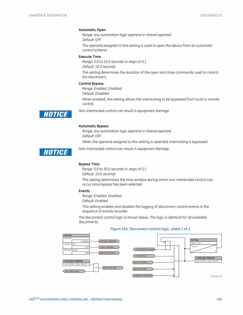
CHAPTER 8: AUTOMATION DISCONNECTS
C90PLUS AUTOMATION LOGIC CONTROLLER – INSTRUCTION MANUAL 293
Automatic OpenRange: any automation logic operand or shared operandDefault: OFF
The operand assigned to this setting is used to open the device from an automatic control scheme.
Execute TimeRange: 0.0 to 10.0 seconds in steps of 0.1Default: 10.0 seconds
This setting determines the duration of the open and close commands used to control the disconnect.
Control BypassRange: Enabled, DisabledDefault: Disabled
When enabled, this setting allows the interlocking to be bypassed from local or remote control.
FASTPATH: Non-interlocked control can result in equipment damage.
Automatic BypassRange: any automation logic operand or shared operandDefault: OFF
When the operand assigned to this setting is asserted, interlocking is bypassed.FASTPATH: Non-interlocked control can result in equipment damage.
Bypass TimeRange: 0.0 to 30.0 seconds in steps of 0.1Default: 10.0 seconds
This setting determines the time window during which non-interlocked control can occur once bypass has been selected.
EventsRange: Enabled, DisabledDefault: Enabled
This setting enables and disables the logging of disconnect control events in the sequence of events recorder.
The disconnect control logic is shown below. The logic is identical for all available disconnects.
Figure 241: Disconnect control logic, sheet 1 of 3
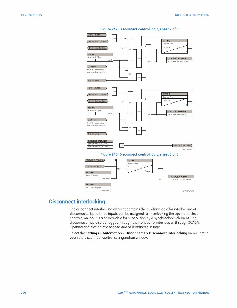
294 C90PLUS AUTOMATION LOGIC CONTROLLER – INSTRUCTION MANUAL
DISCONNECTS CHAPTER 8: AUTOMATION
Figure 242: Disconnect control logic, sheet 2 of 3
Figure 243: Disconnect control logic, sheet 3 of 3
Disconnect interlockingThe disconnect interlocking element contains the auxiliary logic for interlocking of disconnects. Up to three inputs can be assigned for interlocking the open and close controls. An input is also available for supervision by a synchrocheck element. The disconnect may also be tagged through the front panel interface or through SCADA. Opening and closing of a tagged device is inhibited in logic.
Select the Settings > Automation > Disconnects > Disconnect Interlocking menu item to open the disconnect control configuration window.
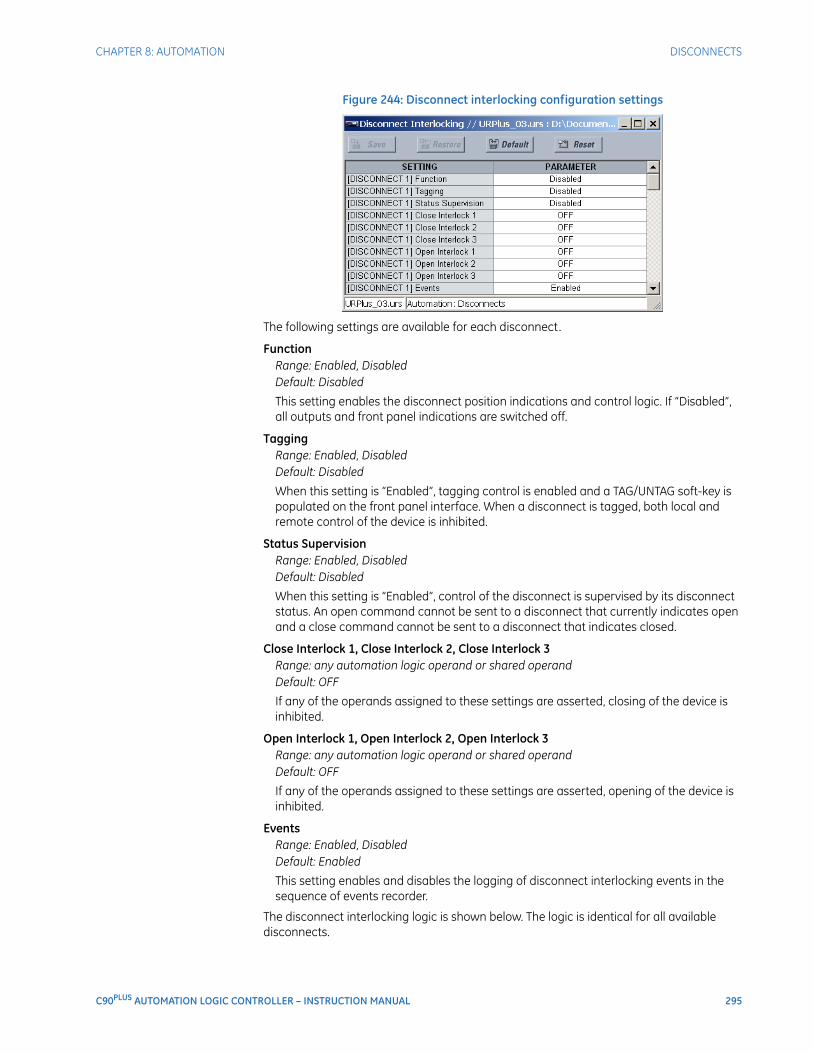
CHAPTER 8: AUTOMATION DISCONNECTS
C90PLUS AUTOMATION LOGIC CONTROLLER – INSTRUCTION MANUAL 295
Figure 244: Disconnect interlocking configuration settings
The following settings are available for each disconnect.
FunctionRange: Enabled, DisabledDefault: Disabled
This setting enables the disconnect position indications and control logic. If “Disabled”, all outputs and front panel indications are switched off.
TaggingRange: Enabled, DisabledDefault: Disabled
When this setting is “Enabled”, tagging control is enabled and a TAG/UNTAG soft-key is populated on the front panel interface. When a disconnect is tagged, both local and remote control of the device is inhibited.
Status SupervisionRange: Enabled, DisabledDefault: Disabled
When this setting is “Enabled”, control of the disconnect is supervised by its disconnect status. An open command cannot be sent to a disconnect that currently indicates open and a close command cannot be sent to a disconnect that indicates closed.
Close Interlock 1, Close Interlock 2, Close Interlock 3Range: any automation logic operand or shared operandDefault: OFF
If any of the operands assigned to these settings are asserted, closing of the device is inhibited.
Open Interlock 1, Open Interlock 2, Open Interlock 3Range: any automation logic operand or shared operandDefault: OFF
If any of the operands assigned to these settings are asserted, opening of the device is inhibited.
EventsRange: Enabled, DisabledDefault: Enabled
This setting enables and disables the logging of disconnect interlocking events in the sequence of events recorder.
The disconnect interlocking logic is shown below. The logic is identical for all available disconnects.
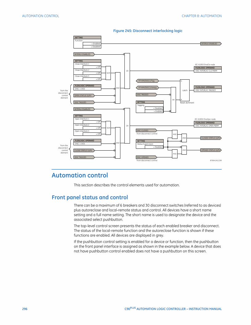
296 C90PLUS AUTOMATION LOGIC CONTROLLER – INSTRUCTION MANUAL
AUTOMATION CONTROL CHAPTER 8: AUTOMATION
Figure 245: Disconnect interlocking logic
Automation controlThis section describes the control elements used for automation.
Front panel status and controlThere can be a maximum of 6 breakers and 30 disconnect switches (referred to as devices) plus autoreclose and local-remote status and control. All devices have a short name setting and a full name setting. The short name is used to designate the device and the associated select pushbutton.
The top-level control screen presents the status of each enabled breaker and disconnect. The status of the local-remote function and the autoreclose function is shown if these functions are enabled. All devices are displayed in grey.
If the pushbutton control setting is enabled for a device or function, then the pushbutton on the front panel interface is assigned as shown in the example below. A device that does not have pushbutton control enabled does not have a pushbutton on this screen.
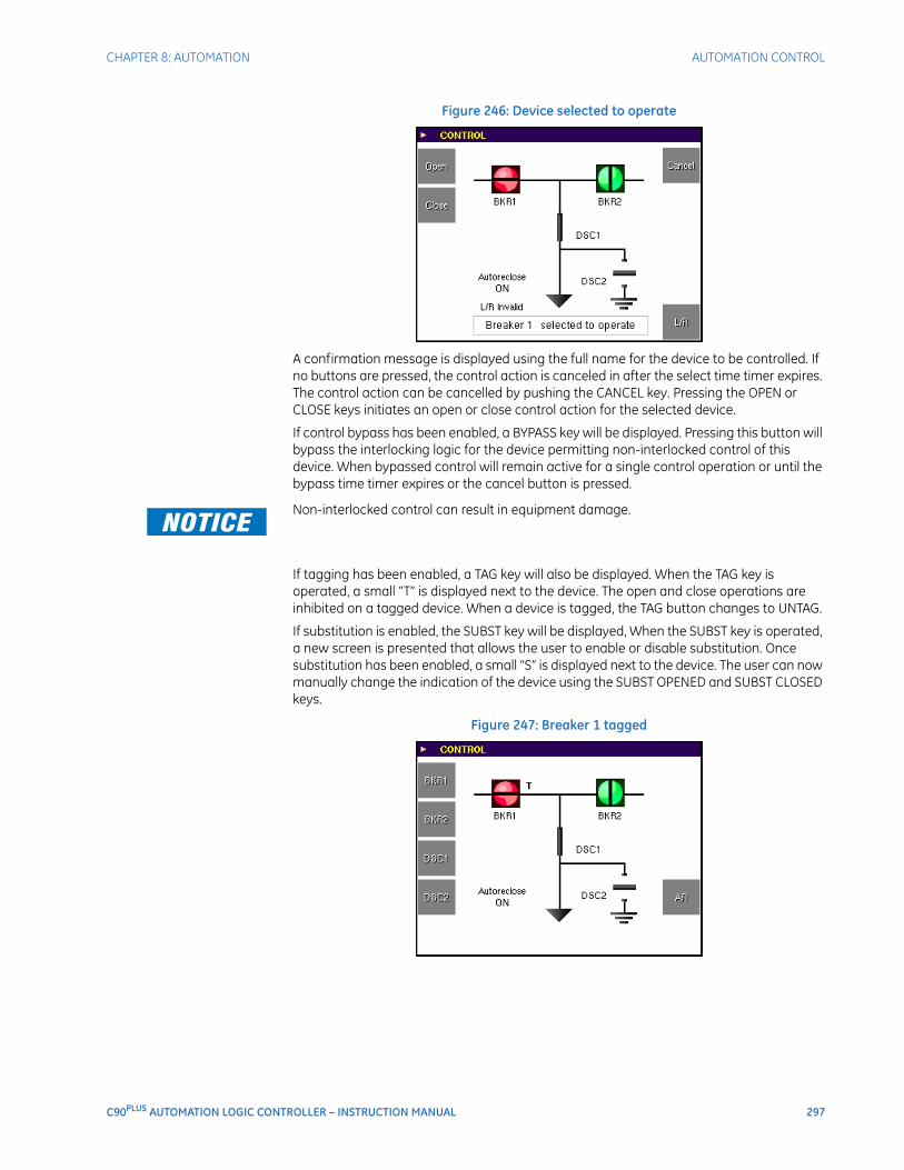
CHAPTER 8: AUTOMATION AUTOMATION CONTROL
C90PLUS AUTOMATION LOGIC CONTROLLER – INSTRUCTION MANUAL 297
Figure 246: Device selected to operate
A confirmation message is displayed using the full name for the device to be controlled. If no buttons are pressed, the control action is canceled in after the select time timer expires. The control action can be cancelled by pushing the CANCEL key. Pressing the OPEN or CLOSE keys initiates an open or close control action for the selected device.
If control bypass has been enabled, a BYPASS key will be displayed. Pressing this button will bypass the interlocking logic for the device permitting non-interlocked control of this device. When bypassed control will remain active for a single control operation or until the bypass time timer expires or the cancel button is pressed.
FASTPATH: Non-interlocked control can result in equipment damage.
If tagging has been enabled, a TAG key will also be displayed. When the TAG key is operated, a small “T” is displayed next to the device. The open and close operations are inhibited on a tagged device. When a device is tagged, the TAG button changes to UNTAG.
If substitution is enabled, the SUBST key will be displayed, When the SUBST key is operated, a new screen is presented that allows the user to enable or disable substitution. Once substitution has been enabled, a small “S” is displayed next to the device. The user can now manually change the indication of the device using the SUBST OPENED and SUBST CLOSED keys.
Figure 247: Breaker 1 tagged
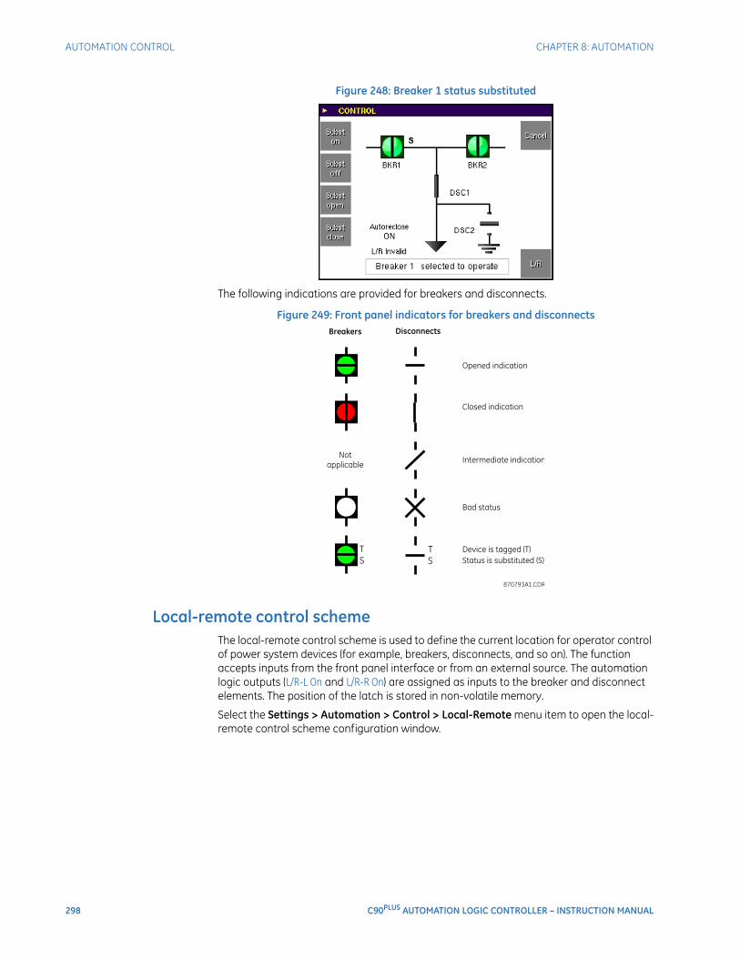
298 C90PLUS AUTOMATION LOGIC CONTROLLER – INSTRUCTION MANUAL
AUTOMATION CONTROL CHAPTER 8: AUTOMATION
Figure 248: Breaker 1 status substituted
The following indications are provided for breakers and disconnects.
Figure 249: Front panel indicators for breakers and disconnects
Local-remote control schemeThe local-remote control scheme is used to define the current location for operator control of power system devices (for example, breakers, disconnects, and so on). The function accepts inputs from the front panel interface or from an external source. The automation logic outputs (L/R-L On and L/R-R On) are assigned as inputs to the breaker and disconnect elements. The position of the latch is stored in non-volatile memory.
Select the Settings > Automation > Control > Local-Remote menu item to open the local-remote control scheme configuration window.
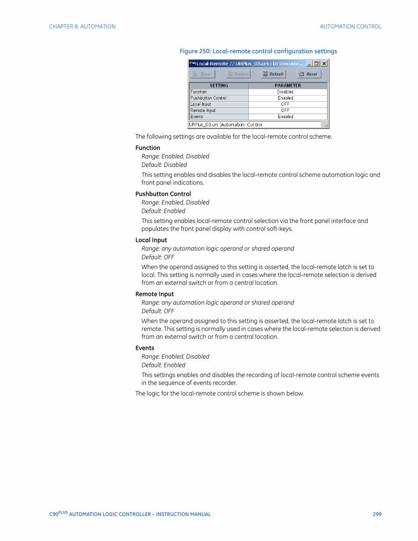
CHAPTER 8: AUTOMATION AUTOMATION CONTROL
C90PLUS AUTOMATION LOGIC CONTROLLER – INSTRUCTION MANUAL 299
Figure 250: Local-remote control configuration settings
The following settings are available for the local-remote control scheme.
FunctionRange: Enabled, DisabledDefault: Disabled
This setting enables and disables the local-remote control scheme automation logic and front panel indications.
Pushbutton ControlRange: Enabled, DisabledDefault: Enabled
This setting enables local-remote control selection via the front panel interface and populates the front panel display with control soft-keys.
Local InputRange: any automation logic operand or shared operandDefault: OFF
When the operand assigned to this setting is asserted, the local-remote latch is set to local. This setting is normally used in cases where the local-remote selection is derived from an external switch or from a central location.
Remote InputRange: any automation logic operand or shared operandDefault: OFF
When the operand assigned to this setting is asserted, the local-remote latch is set to remote. This setting is normally used in cases where the local-remote selection is derived from an external switch or from a central location.
EventsRange: Enabled, DisabledDefault: Enabled
This settings enables and disables the recording of local-remote control scheme events in the sequence of events recorder.
The logic for the local-remote control scheme is shown below.
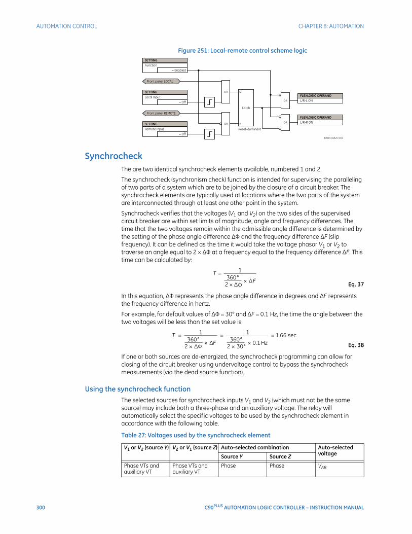
300 C90PLUS AUTOMATION LOGIC CONTROLLER – INSTRUCTION MANUAL
AUTOMATION CONTROL CHAPTER 8: AUTOMATION
Figure 251: Local-remote control scheme logic
SynchrocheckThe are two identical synchrocheck elements available, numbered 1 and 2.
The synchrocheck (synchronism check) function is intended for supervising the paralleling of two parts of a system which are to be joined by the closure of a circuit breaker. The synchrocheck elements are typically used at locations where the two parts of the system are interconnected through at least one other point in the system.
Synchrocheck verifies that the voltages (V1 and V2) on the two sides of the supervised circuit breaker are within set limits of magnitude, angle and frequency differences. The time that the two voltages remain within the admissible angle difference is determined by the setting of the phase angle difference ∆Φ and the frequency difference ∆F (slip frequency). It can be defined as the time it would take the voltage phasor V1 or V2 to traverse an angle equal to 2 × ∆Φ at a frequency equal to the frequency difference ∆F. This time can be calculated by:
Eq. 37
In this equation, ∆Φ represents the phase angle difference in degrees and ∆F represents the frequency difference in hertz.
For example, for default values of ∆Φ = 30° and ∆F = 0.1 Hz, the time the angle between the two voltages will be less than the set value is:
Eq. 38
If one or both sources are de-energized, the synchrocheck programming can allow for closing of the circuit breaker using undervoltage control to bypass the synchrocheck measurements (via the dead source function).
Using the synchrocheck functionThe selected sources for synchrocheck inputs V1 and V2 (which must not be the same source) may include both a three-phase and an auxiliary voltage. The relay will automatically select the specific voltages to be used by the synchrocheck element in accordance with the following table.
Table 27: Voltages used by the synchrocheck element
V1 or V2 (source Y) V2 or V1 (source Z) Auto-selected combination Auto-selected voltageSource Y Source Z
Phase VTs and auxiliary VT
Phase VTs and auxiliary VT
Phase Phase VAB
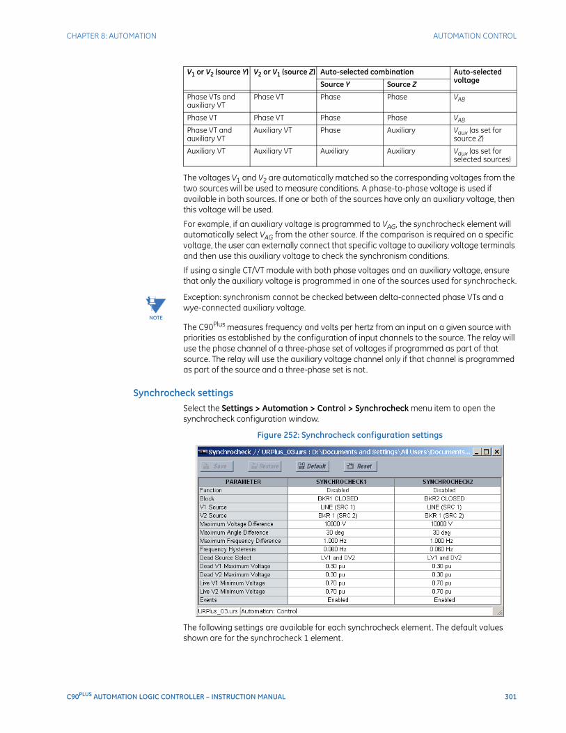
CHAPTER 8: AUTOMATION AUTOMATION CONTROL
C90PLUS AUTOMATION LOGIC CONTROLLER – INSTRUCTION MANUAL 301
The voltages V1 and V2 are automatically matched so the corresponding voltages from the two sources will be used to measure conditions. A phase-to-phase voltage is used if available in both sources. If one or both of the sources have only an auxiliary voltage, then this voltage will be used.
For example, if an auxiliary voltage is programmed to VAG, the synchrocheck element will automatically select VAG from the other source. If the comparison is required on a specific voltage, the user can externally connect that specific voltage to auxiliary voltage terminals and then use this auxiliary voltage to check the synchronism conditions.
If using a single CT/VT module with both phase voltages and an auxiliary voltage, ensure that only the auxiliary voltage is programmed in one of the sources used for synchrocheck.
NOTE
NOTE: Exception: synchronism cannot be checked between delta-connected phase VTs and a wye-connected auxiliary voltage.
The C90Plus measures frequency and volts per hertz from an input on a given source with priorities as established by the configuration of input channels to the source. The relay will use the phase channel of a three-phase set of voltages if programmed as part of that source. The relay will use the auxiliary voltage channel only if that channel is programmed as part of the source and a three-phase set is not.
Synchrocheck settingsSelect the Settings > Automation > Control > Synchrocheck menu item to open the synchrocheck configuration window.
Figure 252: Synchrocheck configuration settings
The following settings are available for each synchrocheck element. The default values shown are for the synchrocheck 1 element.
Phase VTs and auxiliary VT
Phase VT Phase Phase VAB
Phase VT Phase VT Phase Phase VAB
Phase VT and auxiliary VT
Auxiliary VT Phase Auxiliary Vaux (as set for source Z)
Auxiliary VT Auxiliary VT Auxiliary Auxiliary Vaux (as set for selected sources)
V1 or V2 (source Y) V2 or V1 (source Z) Auto-selected combination Auto-selected voltageSource Y Source Z
302 C90PLUS AUTOMATION LOGIC CONTROLLER – INSTRUCTION MANUAL
AUTOMATION CONTROL CHAPTER 8: AUTOMATION
FunctionRange: Enabled, DisabledDefault: Disabled
This setting enables the synchrocheck position indications and control logic. If disabled, all synchrocheck outputs and front panel indications are switched off.
BlockRange: any automation logic operand or shared operandDefault: BKR1 CLOSED
Assertion of the operand assigned to this setting will block operation of the synchrocheck element.
V1 SourceRange: LINE (SRC 1), BKR 1 (SRC 2), BKR 2 (SRC 3)Default: LINE (SRC 1)
This setting selects the source for the V1 voltage.
V2 SourceRange: LINE (SRC 1), BKR 1 (SRC 2), BKR 2 (SRC 3)Default: BKR 1 (SRC 2)
This setting selects the source for the V2 voltage.
Maximum Voltage DifferenceRange: 0 to 400000 volts in steps of 1Default: 10000 volts
This setting specifies the maximum primary voltage difference (in volts) between the two sources. A primary voltage magnitude difference between the two input voltages less than this value is within the permissible limit for synchronism.
Maximum Angle DifferenceRange: 0 to 100° in steps of 1Default: 30°
This setting specifies the maximum angular difference (in degrees) between the two sources. An angular difference between the two input voltage phasors less than this value is within the permissible limit for synchronism.
Maximum Frequency DifferenceRange: 0.00 to 2.00 Hz in steps of 0.01Default: 1.00 Hz
This setting selects the maximum frequency difference (in hertz) between the two sources. A frequency difference between the two input voltage systems below this value is within the permissible limit for synchronism.
Frequency HysteresisRange: 0.00 to 0.10 Hz in steps of 0.01Default: 0.06 Hz
This setting specifies the required hysteresis for the maximum frequency difference condition. The condition becomes satisfied when the frequency difference is less than the value specified by the Maximum Frequency Difference setting. Once the synchrocheck element has operated, the frequency difference must increase above the sum of this setting and the Maximum Frequency Difference setting to drop out (assuming the other two conditions, voltage and angle, remain satisfied).

CHAPTER 8: AUTOMATION AUTOMATION CONTROL
C90PLUS AUTOMATION LOGIC CONTROLLER – INSTRUCTION MANUAL 303
Dead Source SelectRange: None, LV1 and DV2, DV1 and LV2, DV1 or DV2, DV1 Xor DV2, DV1 and DV2Default: LV1 and DV2
This setting selects the combination of dead and live sources that will bypass the synchronism check function and permit the breaker to be closed when one or both of the two voltages (V1 and V2) are below the maximum voltage threshold. A dead or live source is declared by monitoring the voltage level. Six options are available:
– “None”: the dead source function is disabled
– “LV1 and DV2”: live V1 and dead V2
– “DV1 and LV2”: dead V1 and live V2
– “DV1 or DV2”: dead V1 or dead V2
– “DV1 Xor DV2”: dead V1 exclusive-or dead V2 (one source is dead and the other is live)
– “DV1 and DV2”: dead V1 and dead V2
Dead V1 Maximum VoltageRange: 0.00 to 1.25 pu in steps of 0.01Default: 0.30 pu
This setting specifies a maximum voltage magnitude for V1 in per-unit values. At values less than this magnitude, the V1 voltage input used for synchrocheck will be considered dead or de-energized.
Dead V2 Maximum VoltageRange: 0.00 to 1.25 pu in steps of 0.01Default: 0.30 pu
This setting specifies a maximum voltage magnitude for V2 in per-unit values. At values less than this magnitude, the V2 voltage input used for synchrocheck will be considered dead or de-energized.
Live V1 Minimum VoltageRange: 0.00 to 1.25 pu in steps of 0.01Default: 0.70 pu
This setting specifies a minimum voltage magnitude for V1 in per-unit values. At values greater than this magnitude, the V1 voltage input used for synchrocheck will be considered live or energized.
Live V2 Minimum VoltageRange: 0.00 to 1.25 pu in steps of 0.01Default: 0.70 pu
This setting specifies a minimum voltage magnitude for V2 in per-unit values. At values greater than this magnitude, the V2 voltage input used for synchrocheck will be considered live or energized.
EventsRange: Enabled, DisabledDefault: Enabled
This setting enables and disables the logging of synchrocheck events in the sequence of events recorder.
The logic for the synchrocheck element is illustrated below.
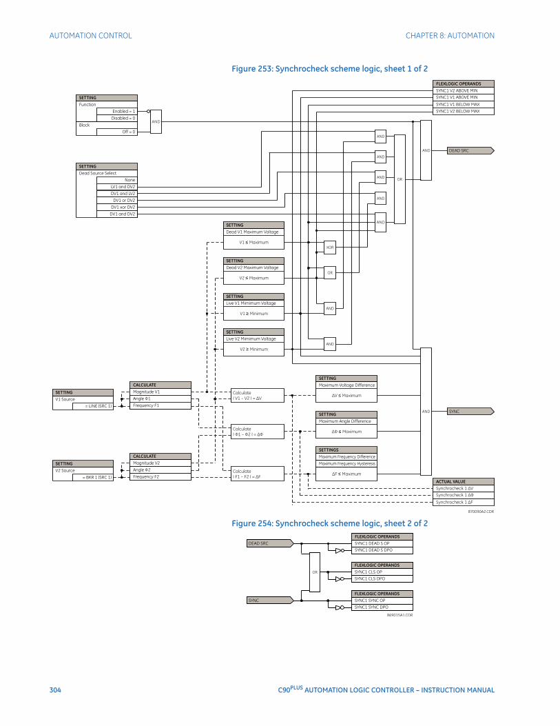
304 C90PLUS AUTOMATION LOGIC CONTROLLER – INSTRUCTION MANUAL
AUTOMATION CONTROL CHAPTER 8: AUTOMATION
Figure 253: Synchrocheck scheme logic, sheet 1 of 2
Figure 254: Synchrocheck scheme logic, sheet 2 of 2

CHAPTER 8: AUTOMATION AUTOMATION CONTROL
C90PLUS AUTOMATION LOGIC CONTROLLER – INSTRUCTION MANUAL 305
Selector switchThe selector switch element is intended to replace a mechanical selector switch. Typical applications include setting group control or control of multiple logic sub-circuits in user-programmable logic.
Selector switch operationThe selector switch provides for two control inputs. The step-up control allows stepping through selector position one step at a time with each pulse of the control input, such as a user-programmable pushbutton. The three-bit control input allows setting the selector to the position defined by a three-bit word.
The element allows pre-selecting a new position without applying it . The pre-selected position gets applied either after time-out or upon acknowledgement via separate inputs (user setting). The selector position is stored in non-volatile memory. Upon power-up, either the previous position is restored or the relay synchronizes to the current three-bit word (user setting). Basic alarm functionality alerts the user under abnormal conditions; for example, the three-bit control input being out of range.
The following figures illustrate the operation of the selector switch. In these diagrams, “T” represents a time-out setting.
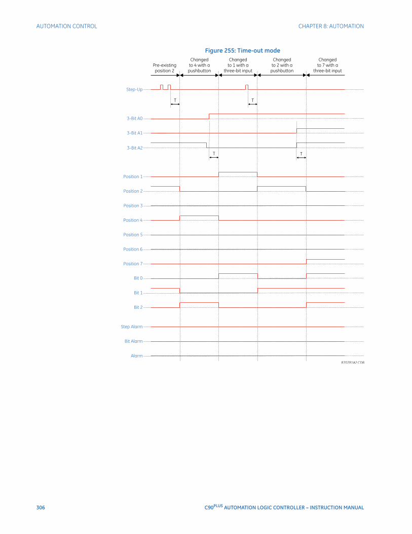
306 C90PLUS AUTOMATION LOGIC CONTROLLER – INSTRUCTION MANUAL
AUTOMATION CONTROL CHAPTER 8: AUTOMATION
Figure 255: Time-out mode
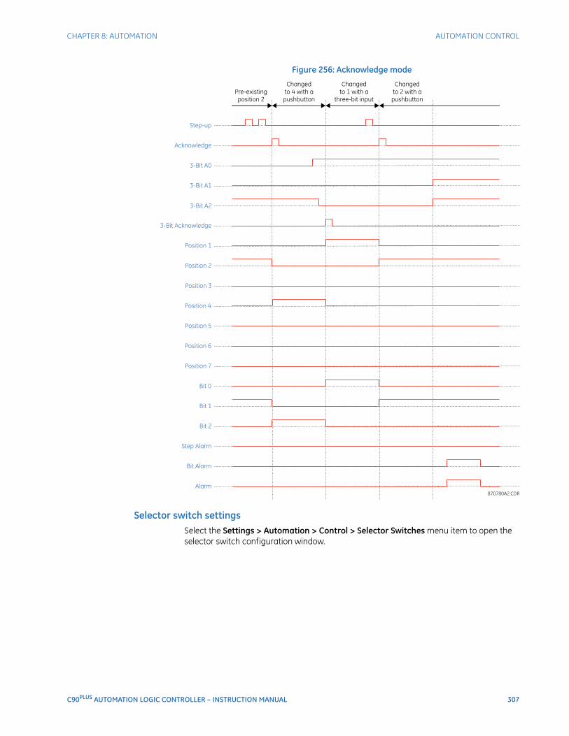
CHAPTER 8: AUTOMATION AUTOMATION CONTROL
C90PLUS AUTOMATION LOGIC CONTROLLER – INSTRUCTION MANUAL 307
Figure 256: Acknowledge mode
Selector switch settingsSelect the Settings > Automation > Control > Selector Switches menu item to open the selector switch configuration window.
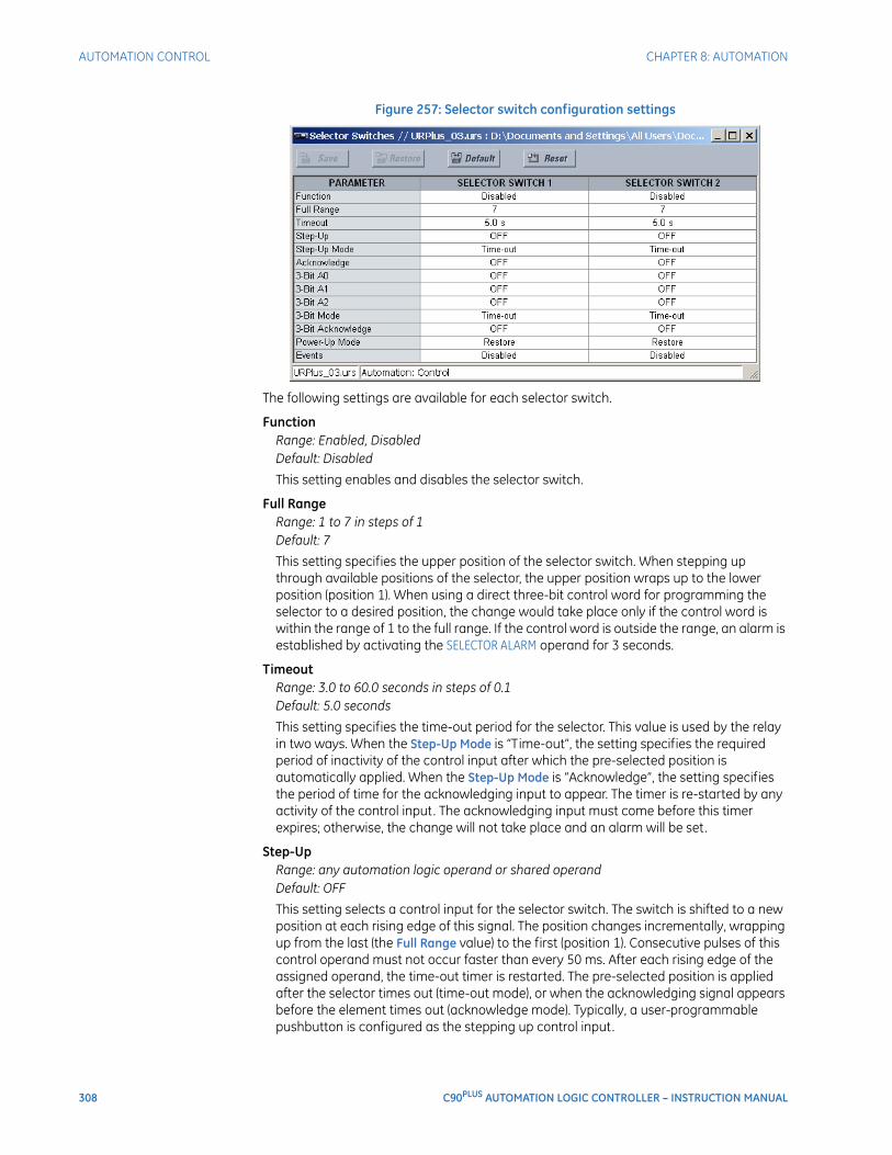
308 C90PLUS AUTOMATION LOGIC CONTROLLER – INSTRUCTION MANUAL
AUTOMATION CONTROL CHAPTER 8: AUTOMATION
Figure 257: Selector switch configuration settings
The following settings are available for each selector switch.
FunctionRange: Enabled, DisabledDefault: Disabled
This setting enables and disables the selector switch.
Full RangeRange: 1 to 7 in steps of 1Default: 7
This setting specifies the upper position of the selector switch. When stepping up through available positions of the selector, the upper position wraps up to the lower position (position 1). When using a direct three-bit control word for programming the selector to a desired position, the change would take place only if the control word is within the range of 1 to the full range. If the control word is outside the range, an alarm is established by activating the SELECTOR ALARM operand for 3 seconds.
TimeoutRange: 3.0 to 60.0 seconds in steps of 0.1Default: 5.0 seconds
This setting specifies the time-out period for the selector. This value is used by the relay in two ways. When the Step-Up Mode is “Time-out”, the setting specifies the required period of inactivity of the control input after which the pre-selected position is automatically applied. When the Step-Up Mode is “Acknowledge”, the setting specifies the period of time for the acknowledging input to appear. The timer is re-started by any activity of the control input. The acknowledging input must come before this timer expires; otherwise, the change will not take place and an alarm will be set.
Step-UpRange: any automation logic operand or shared operandDefault: OFF
This setting selects a control input for the selector switch. The switch is shifted to a new position at each rising edge of this signal. The position changes incrementally, wrapping up from the last (the Full Range value) to the first (position 1). Consecutive pulses of this control operand must not occur faster than every 50 ms. After each rising edge of the assigned operand, the time-out timer is restarted. The pre-selected position is applied after the selector times out (time-out mode), or when the acknowledging signal appears before the element times out (acknowledge mode). Typically, a user-programmable pushbutton is configured as the stepping up control input.

CHAPTER 8: AUTOMATION AUTOMATION CONTROL
C90PLUS AUTOMATION LOGIC CONTROLLER – INSTRUCTION MANUAL 309
Step-Up ModeRange: Time-out, AcknowledgeDefault: Time-out
This setting defines the selector mode of operation. When set to “Time-out”, the selector will change its position after a pre-defined period of inactivity at the control input. The change is automatic and does not require any explicit confirmation of the intent to change the selector's position. When set to “Acknowledge”, the selector will change its position only after the intent is confirmed through a separate acknowledging signal. If the acknowledging signal does not appear within a pre-defined period of time, the selector does not accept the change and an alarm is established by setting the SELECTOR STP ALARM output FlexLogic™ operand for 3 seconds.
AcknowledgeRange: any automation logic operand or shared operandDefault: OFF
This setting selects an acknowledging input for the stepping up control input. The pre-selected position is applied on the rising edge of the assigned operand. This setting is active only under the acknowledge mode of operation. The acknowledging signal must appear within the time defined by the Timeout setting after the last activity of the control input. A user-programmable pushbutton is typically configured as the acknowledging input.
3-Bit A0, 3-Bit A1, 3-Bit A2Range: any automation logic operand or shared operandDefault: OFF
These settings specify a three-bit control input of the selector. The three-bit control word pre-selects the position using the following encoding convention.
Table 28: Selector switch three-bit control word
The rest position (0, 0, 0) does not generate an action and is intended for situations when the device generating the three-bit control word is having a problem. When in time-out mode, the pre-selected position is applied in the time specified (in seconds) by the Timeout setting after the last activity of the three-bit input. When in acknowledge mode, the pre-selected position is applied on the rising edge of the acknowledging input specified by the 3-Bit Acknowledge setting.
The stepping up control input (selected by the Step-Up setting) and the three-bit control inputs (A0, A1, and A2) lock-out mutually. Once the stepping up sequence is initiated, the three-bit control input is inactive; once the three-bit control sequence is initiated, the stepping up input is inactive.
A2 A1 A0 Position
0 0 0 rest
0 0 1 1
0 1 0 2
0 1 1 3
1 0 0 4
1 0 1 5
1 1 0 6
1 1 1 7
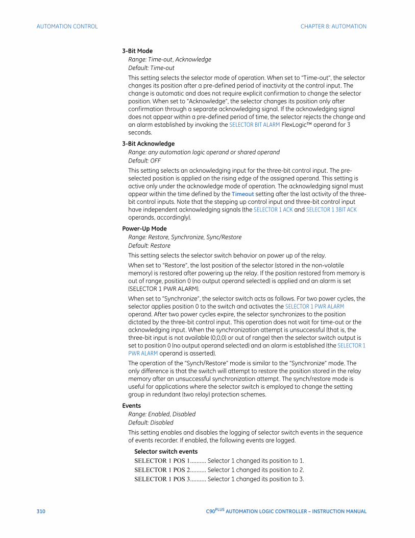
310 C90PLUS AUTOMATION LOGIC CONTROLLER – INSTRUCTION MANUAL
AUTOMATION CONTROL CHAPTER 8: AUTOMATION
3-Bit ModeRange: Time-out, AcknowledgeDefault: Time-out
This setting selects the selector mode of operation. When set to “Time-out”, the selector changes its position after a pre-defined period of inactivity at the control input. The change is automatic and does not require explicit confirmation to change the selector position. When set to “Acknowledge”, the selector changes its position only after confirmation through a separate acknowledging signal. If the acknowledging signal does not appear within a pre-defined period of time, the selector rejects the change and an alarm established by invoking the SELECTOR BIT ALARM FlexLogic™ operand for 3 seconds.
3-Bit AcknowledgeRange: any automation logic operand or shared operandDefault: OFF
This setting selects an acknowledging input for the three-bit control input. The pre-selected position is applied on the rising edge of the assigned operand. This setting is active only under the acknowledge mode of operation. The acknowledging signal must appear within the time defined by the Timeout setting after the last activity of the three-bit control inputs. Note that the stepping up control input and three-bit control input have independent acknowledging signals (the SELECTOR 1 ACK and SELECTOR 1 3BIT ACK operands, accordingly).
Power-Up ModeRange: Restore, Synchronize, Sync/RestoreDefault: Restore
This setting selects the selector switch behavior on power up of the relay.
When set to “Restore”, the last position of the selector (stored in the non-volatile memory) is restored after powering up the relay. If the position restored from memory is out of range, position 0 (no output operand selected) is applied and an alarm is set (SELECTOR 1 PWR ALARM).
When set to “Synchronize”, the selector switch acts as follows. For two power cycles, the selector applies position 0 to the switch and activates the SELECTOR 1 PWR ALARM operand. After two power cycles expire, the selector synchronizes to the position dictated by the three-bit control input. This operation does not wait for time-out or the acknowledging input. When the synchronization attempt is unsuccessful (that is, the three-bit input is not available (0,0,0) or out of range) then the selector switch output is set to position 0 (no output operand selected) and an alarm is established (the SELECTOR 1 PWR ALARM operand is asserted).
The operation of the “Synch/Restore” mode is similar to the “Synchronize” mode. The only difference is that the switch will attempt to restore the position stored in the relay memory after an unsuccessful synchronization attempt. The synch/restore mode is useful for applications where the selector switch is employed to change the setting group in redundant (two relay) protection schemes.
EventsRange: Enabled, DisabledDefault: Disabled
This setting enables and disables the logging of selector switch events in the sequence of events recorder. If enabled, the following events are logged.
Selector switch eventsSELECTOR 1 POS 1.......... Selector 1 changed its position to 1.SELECTOR 1 POS 2.......... Selector 1 changed its position to 2.SELECTOR 1 POS 3.......... Selector 1 changed its position to 3.
CHAPTER 8: AUTOMATION LOAD SHEDDING
C90PLUS AUTOMATION LOGIC CONTROLLER – INSTRUCTION MANUAL 311
SELECTOR 1 POS 4 .......... Selector 1 changed its position to 4.SELECTOR 1 POS 5 .......... Selector 1 changed its position to 5.SELECTOR 1 POS 6 .......... Selector 1 changed its position to 6.SELECTOR 1 POS 7 .......... Selector 1 changed its position to 7.SELECTOR 1 STP ALARMThe selector position pre-selected via the stepping up
control input has not been confirmed before the time out.SELECTOR 1 BIT ALARMThe selector position pre-selected via the three-bit control
input has not been confirmed before the time out.SELECTOR 2... ................... The set of events shown above are available for selector
switch 2.
The logic for the selector switch is shown below.
Figure 258: Selector switch logic
Load sheddingMultiple stages of underfrequency, undervoltage, and frequency rate of change elements can be used to initiate load shedding or remedial actions schemes. These elements can also initiate frequency-based load restoration schemes during lack of generation in the network or due to sudden load drops. The advanced automation capabilities of the C90Plus allow flexible special protection schemes, advanced load shedding schemes, and load restoration schemes to be built .
Load shedding sourceSelect the Settings > Automation > Load Shedding > Source menu item to open the load shedding sources configuration window.
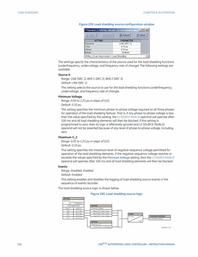
312 C90PLUS AUTOMATION LOGIC CONTROLLER – INSTRUCTION MANUAL
LOAD SHEDDING CHAPTER 8: AUTOMATION
Figure 259: Load shedding source configuration window
The settings specify the characteristics of the source used for the load shedding functions (underfrequency, undervoltage, and frequency rate of change). The following settings are available.
Source ARange: LINE (SRC 1), BKR 1 (SRC 2), BKR 2 (SRC 3)Default: LINE (SRC 1)
This setting selects the source to use for the load shedding functions (underfrequency, undervoltage, and frequency rate of change).
Minimum VoltageRange: 0.00 to 1.25 pu in steps of 0.01Default: 0.10 pu
This setting specifies the minimum phase-to-phase voltage required on all three phases for operation of the load shedding feature. That is, if any phase-to-phase voltage is less than the value specified by this setting, the LS SOURCE INVALID operand will operate after 100 ms and all load shedding elements will then be blocked. If this setting is programmed to zero, then its logic is effectively ignored and LS SOURCE INVALID operand will not be asserted because of any level of phase-to-phase voltage, including zero.
Maximum V_2Range: 0.05 to 1.25 pu in steps of 0.01Default: 0.10 pu
This setting specifies the maximum level of negative-sequence voltage permitted for operation of the load shedding elements. If the negative-sequence voltage reaches or exceeds the values specified by the Minimum Voltage setting, then the LS SOURCE INVALID operand will operate after 100 ms and all load shedding elements will then be blocked.
EventsRange: Disabled, EnabledDefault: Enabled
This setting enables and disables the logging of load shedding source events in the sequence of events recorder.
The load shedding source logic is shown below.
Figure 260: Load shedding source logic
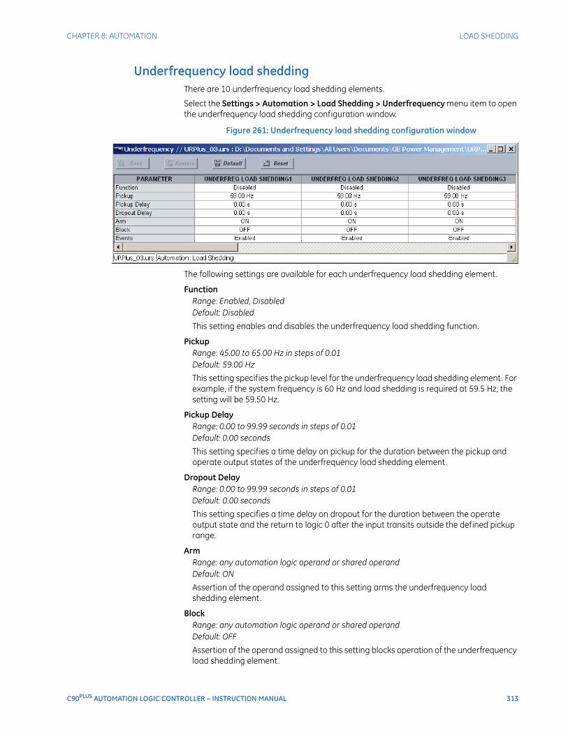
CHAPTER 8: AUTOMATION LOAD SHEDDING
C90PLUS AUTOMATION LOGIC CONTROLLER – INSTRUCTION MANUAL 313
Underfrequency load sheddingThere are 10 underfrequency load shedding elements.
Select the Settings > Automation > Load Shedding > Underfrequency menu item to open the underfrequency load shedding configuration window.
Figure 261: Underfrequency load shedding configuration window
The following settings are available for each underfrequency load shedding element.
FunctionRange: Enabled, DisabledDefault: Disabled
This setting enables and disables the underfrequency load shedding function.
PickupRange: 45.00 to 65.00 Hz in steps of 0.01Default: 59.00 Hz
This setting specifies the pickup level for the underfrequency load shedding element. For example, if the system frequency is 60 Hz and load shedding is required at 59.5 Hz, the setting will be 59.50 Hz.
Pickup DelayRange: 0.00 to 99.99 seconds in steps of 0.01Default: 0.00 seconds
This setting specifies a time delay on pickup for the duration between the pickup and operate output states of the underfrequency load shedding element.
Dropout DelayRange: 0.00 to 99.99 seconds in steps of 0.01Default: 0.00 seconds
This setting specifies a time delay on dropout for the duration between the operate output state and the return to logic 0 after the input transits outside the defined pickup range.
ArmRange: any automation logic operand or shared operandDefault: ON
Assertion of the operand assigned to this setting arms the underfrequency load shedding element.
BlockRange: any automation logic operand or shared operandDefault: OFF
Assertion of the operand assigned to this setting blocks operation of the underfrequency load shedding element.
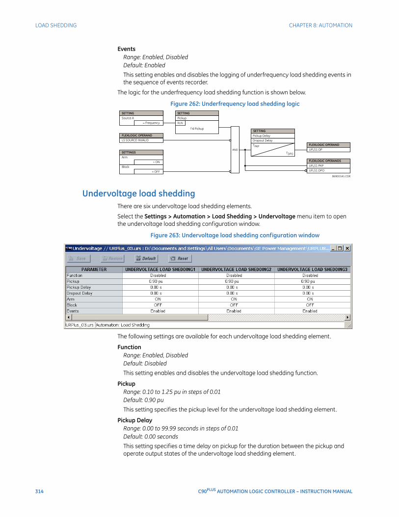
314 C90PLUS AUTOMATION LOGIC CONTROLLER – INSTRUCTION MANUAL
LOAD SHEDDING CHAPTER 8: AUTOMATION
EventsRange: Enabled, DisabledDefault: Enabled
This setting enables and disables the logging of underfrequency load shedding events in the sequence of events recorder.
The logic for the underfrequency load shedding function is shown below.
Figure 262: Underfrequency load shedding logic
Undervoltage load sheddingThere are six undervoltage load shedding elements.
Select the Settings > Automation > Load Shedding > Undervoltage menu item to open the undervoltage load shedding configuration window.
Figure 263: Undervoltage load shedding configuration window
The following settings are available for each undervoltage load shedding element.
FunctionRange: Enabled, DisabledDefault: Disabled
This setting enables and disables the undervoltage load shedding function.
PickupRange: 0.10 to 1.25 pu in steps of 0.01Default: 0.90 pu
This setting specifies the pickup level for the undervoltage load shedding element.
Pickup DelayRange: 0.00 to 99.99 seconds in steps of 0.01Default: 0.00 seconds
This setting specifies a time delay on pickup for the duration between the pickup and operate output states of the undervoltage load shedding element.

CHAPTER 8: AUTOMATION LOAD SHEDDING
C90PLUS AUTOMATION LOGIC CONTROLLER – INSTRUCTION MANUAL 315
Dropout DelayRange: 0.00 to 99.99 seconds in steps of 0.01Default: 0.00 seconds
This setting specifies a time delay on dropout for the duration between the operate output state and the return to logic 0 after the input transits outside the defined pickup range.
ArmRange: any automation logic operand or shared operandDefault: ON
Assertion of the operand assigned to this setting arms the undervoltage load shedding element.
BlockRange: any automation logic operand or shared operandDefault: OFF
Assertion of the operand assigned to this setting blocks operation of the undervoltage load shedding element.
EventsRange: Enabled, DisabledDefault: Enabled
This setting enables and disables the logging of undervoltage load shedding events in the sequence of events recorder.
The logic for the undervoltage load shedding function is shown below.
Figure 264: Undervoltage load shedding logic
Frequency rate of change load sheddingThere are four frequency rate of change load shedding elements.
Select the Settings > Automation > Load Shedding > Frequency Rate of Change menu item to open the frequency rate of change load shedding configuration window.
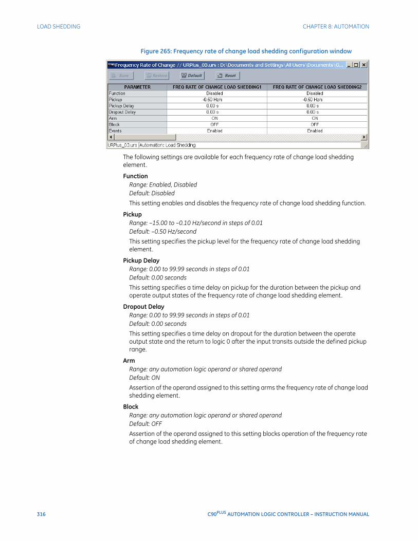
316 C90PLUS AUTOMATION LOGIC CONTROLLER – INSTRUCTION MANUAL
LOAD SHEDDING CHAPTER 8: AUTOMATION
Figure 265: Frequency rate of change load shedding configuration window
The following settings are available for each frequency rate of change load shedding element.
FunctionRange: Enabled, DisabledDefault: Disabled
This setting enables and disables the frequency rate of change load shedding function.
PickupRange: –15.00 to –0.10 Hz/second in steps of 0.01Default: –0.50 Hz/second
This setting specifies the pickup level for the frequency rate of change load shedding element.
Pickup DelayRange: 0.00 to 99.99 seconds in steps of 0.01Default: 0.00 seconds
This setting specifies a time delay on pickup for the duration between the pickup and operate output states of the frequency rate of change load shedding element.
Dropout DelayRange: 0.00 to 99.99 seconds in steps of 0.01Default: 0.00 seconds
This setting specifies a time delay on dropout for the duration between the operate output state and the return to logic 0 after the input transits outside the defined pickup range.
ArmRange: any automation logic operand or shared operandDefault: ON
Assertion of the operand assigned to this setting arms the frequency rate of change load shedding element.
BlockRange: any automation logic operand or shared operandDefault: OFF
Assertion of the operand assigned to this setting blocks operation of the frequency rate of change load shedding element.
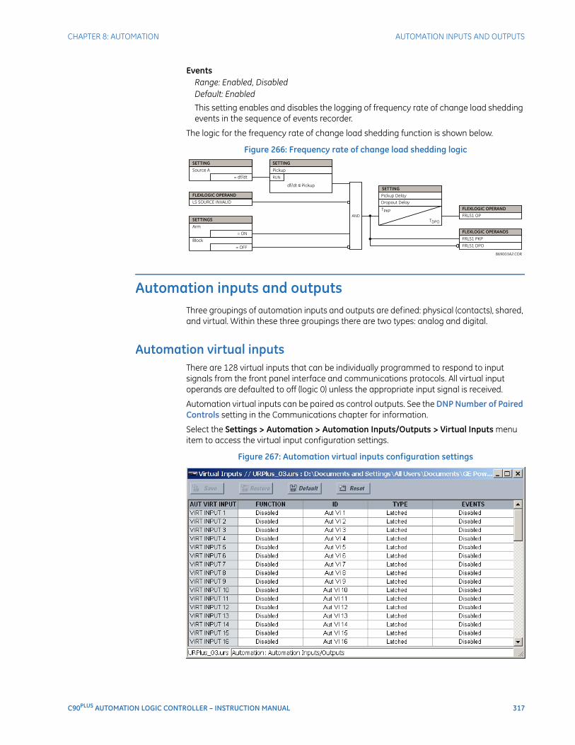
CHAPTER 8: AUTOMATION AUTOMATION INPUTS AND OUTPUTS
C90PLUS AUTOMATION LOGIC CONTROLLER – INSTRUCTION MANUAL 317
EventsRange: Enabled, DisabledDefault: Enabled
This setting enables and disables the logging of frequency rate of change load shedding events in the sequence of events recorder.
The logic for the frequency rate of change load shedding function is shown below.
Figure 266: Frequency rate of change load shedding logic
Automation inputs and outputsThree groupings of automation inputs and outputs are defined: physical (contacts), shared, and virtual. Within these three groupings there are two types: analog and digital.
Automation virtual inputsThere are 128 virtual inputs that can be individually programmed to respond to input signals from the front panel interface and communications protocols. All virtual input operands are defaulted to off (logic 0) unless the appropriate input signal is received.
Automation virtual inputs can be paired as control outputs. See the DNP Number of Paired Controls setting in the Communications chapter for information.
Select the Settings > Automation > Automation Inputs/Outputs > Virtual Inputs menu item to access the virtual input configuration settings.
Figure 267: Automation virtual inputs configuration settings
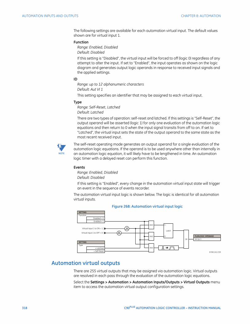
318 C90PLUS AUTOMATION LOGIC CONTROLLER – INSTRUCTION MANUAL
AUTOMATION INPUTS AND OUTPUTS CHAPTER 8: AUTOMATION
The following settings are available for each automation virtual input. The default values shown are for virtual input 1.
FunctionRange: Enabled, DisabledDefault: Disabled
If this setting is “Disabled”, the virtual input will be forced to off (logic 0) regardless of any attempt to alter the input. If set to “Enabled”, the input operates as shown on the logic diagram and generates output logic operands in response to received input signals and the applied settings.
IDRange: up to 12 alphanumeric charactersDefault: Aut VI 1
This setting specifies an identifier that may be assigned to each virtual input.
TypeRange: Self-Reset, LatchedDefault: Latched
There are two types of operation: self-reset and latched. If this settings is “Self-Reset”, the output operand will be asserted (logic 1) for only one evaluation of the automation logic equations and then return to 0 when the input signal transits from off to on. If set to “Latched”, the virtual input sets the state of the output operand to the same state as the most recent received input.
NOTE
NOTE: The self-reset operating mode generates an output operand for a single evaluation of the automation logic equations. If the operand is to be used anywhere other than internally in an automation logic equation, it will likely have to be lengthened in time. An automation logic timer with a delayed reset can perform this function.
EventsRange: Enabled, DisabledDefault: Disabled
If this setting is “Enabled”, every change in the automation virtual input state will trigger an event in the sequence of events recorder.
The automation virtual input logic is shown below. The logic is identical for all automation virtual inputs.
Figure 268: Automation virtual input logic
Automation virtual outputsThere are 255 virtual outputs that may be assigned via automation logic. Virtual outputs are resolved in each pass through the evaluation of the automation logic equations.
Select the Settings > Automation > Automation Inputs/Outputs > Virtual Outputs menu item to access the automation virtual output configuration settings.
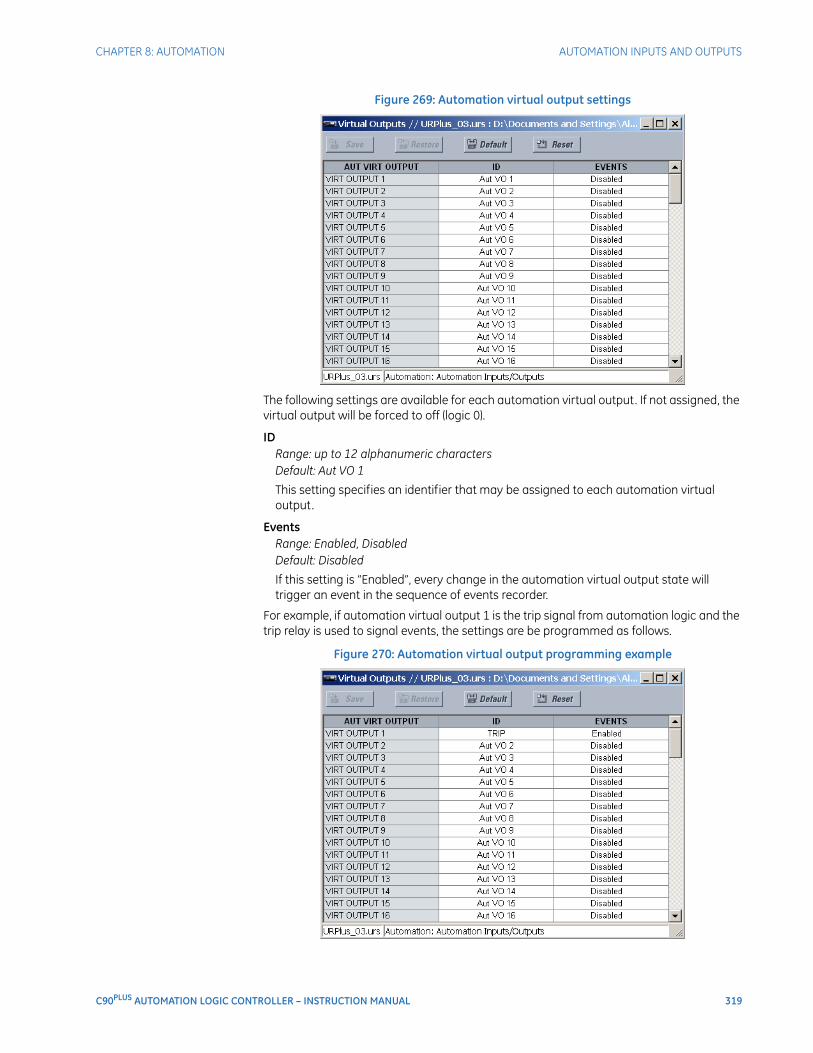
CHAPTER 8: AUTOMATION AUTOMATION INPUTS AND OUTPUTS
C90PLUS AUTOMATION LOGIC CONTROLLER – INSTRUCTION MANUAL 319
Figure 269: Automation virtual output settings
The following settings are available for each automation virtual output. If not assigned, the virtual output will be forced to off (logic 0).
IDRange: up to 12 alphanumeric charactersDefault: Aut VO 1
This setting specifies an identifier that may be assigned to each automation virtual output.
EventsRange: Enabled, DisabledDefault: Disabled
If this setting is “Enabled”, every change in the automation virtual output state will trigger an event in the sequence of events recorder.
For example, if automation virtual output 1 is the trip signal from automation logic and the trip relay is used to signal events, the settings are be programmed as follows.
Figure 270: Automation virtual output programming example

320 C90PLUS AUTOMATION LOGIC CONTROLLER – INSTRUCTION MANUAL
AUTOMATION INPUTS AND OUTPUTS CHAPTER 8: AUTOMATION
Contact input and output default assignmentWhen a new settings file is created, the available contacts are automatically assigned to the protection or automation functions according to the following convention.
• First I/O module → protection.
• All subsequent I/O modules → automation.
For example, if a C90Plus is configured with contact input/output cards in slots E, F, and G, then the inputs and outputs associated with slot E are assigned to protection and the inputs and outputs associated with slots F and G are assigned to automation.
These default assignments may be changed to match the requirements of the application. This is done by right-clicking on the setting filename and choosing the menu Manage Settings File > I/O Assignments menu item. The following window is displayed.
Figure 271: Contact input and output assignments
All available contact inputs and output can be reassigned using the >> and << buttons.
Contact input configurationThe C90Plus can monitor the status of up to 115 field contacts. Each input can be wetted from the C90Plus 48 volt auxiliary supply or from an external power supply. Each digital input has a dedicated delay timer for filtering of contact bouncing. The C90Plus can also detect an oscillating input via the chatter feature. Each contact input active impedance circuitry to provide security against false turn-on of an input due to excessive stray capacitance of field wiring.
A raw status is scanned synchronously for all contact inputs at the rate of 0.25 ms as shown below. A new contact input state must be maintained for a user-programmable debounce time for the C90Plus to validate the new contact state. The debounce time is set
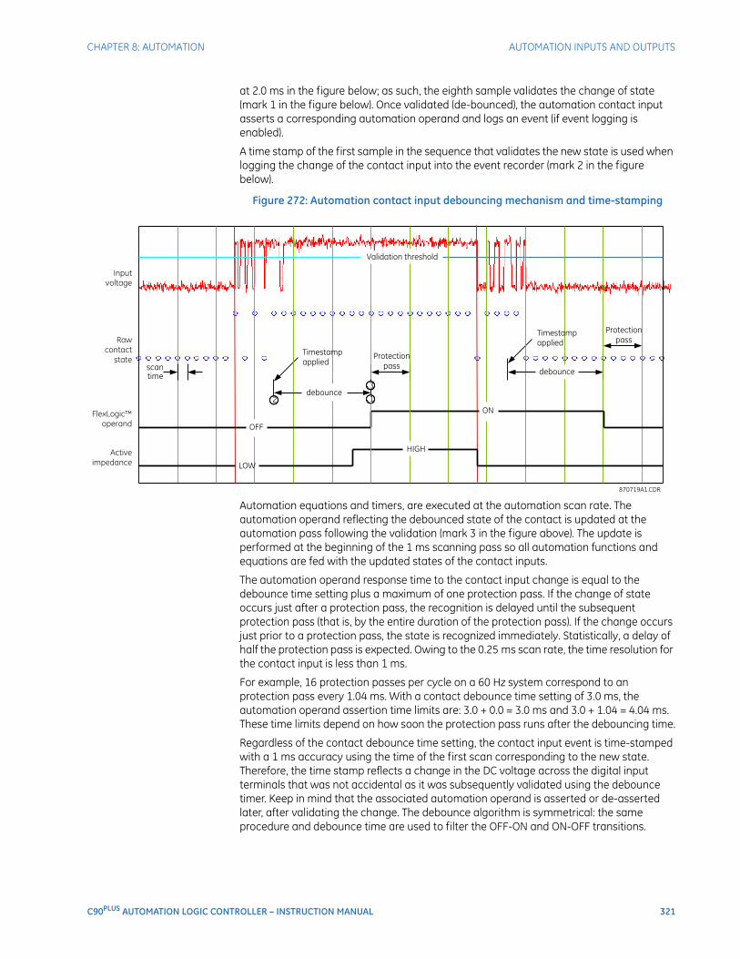
CHAPTER 8: AUTOMATION AUTOMATION INPUTS AND OUTPUTS
C90PLUS AUTOMATION LOGIC CONTROLLER – INSTRUCTION MANUAL 321
at 2.0 ms in the figure below; as such, the eighth sample validates the change of state (mark 1 in the figure below). Once validated (de-bounced), the automation contact input asserts a corresponding automation operand and logs an event (if event logging is enabled).
A time stamp of the first sample in the sequence that validates the new state is used when logging the change of the contact input into the event recorder (mark 2 in the figure below).
Figure 272: Automation contact input debouncing mechanism and time-stamping
Automation equations and timers, are executed at the automation scan rate. The automation operand reflecting the debounced state of the contact is updated at the automation pass following the validation (mark 3 in the figure above). The update is performed at the beginning of the 1 ms scanning pass so all automation functions and equations are fed with the updated states of the contact inputs.
The automation operand response time to the contact input change is equal to the debounce time setting plus a maximum of one protection pass. If the change of state occurs just after a protection pass, the recognition is delayed until the subsequent protection pass (that is, by the entire duration of the protection pass). If the change occurs just prior to a protection pass, the state is recognized immediately. Statistically, a delay of half the protection pass is expected. Owing to the 0.25 ms scan rate, the time resolution for the contact input is less than 1 ms.
For example, 16 protection passes per cycle on a 60 Hz system correspond to an protection pass every 1.04 ms. With a contact debounce time setting of 3.0 ms, the automation operand assertion time limits are: 3.0 + 0.0 = 3.0 ms and 3.0 + 1.04 = 4.04 ms. These time limits depend on how soon the protection pass runs after the debouncing time.
Regardless of the contact debounce time setting, the contact input event is time-stamped with a 1 ms accuracy using the time of the first scan corresponding to the new state. Therefore, the time stamp reflects a change in the DC voltage across the digital input terminals that was not accidental as it was subsequently validated using the debounce timer. Keep in mind that the associated automation operand is asserted or de-asserted later, after validating the change. The debounce algorithm is symmetrical: the same procedure and debounce time are used to filter the OFF-ON and ON-OFF transitions.
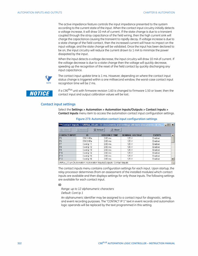
322 C90PLUS AUTOMATION LOGIC CONTROLLER – INSTRUCTION MANUAL
AUTOMATION INPUTS AND OUTPUTS CHAPTER 8: AUTOMATION
The active impedance feature controls the input impedance presented to the system according to the current state of the input. When the contact input circuitry initially detects a voltage increase, it will draw 10 mA of current. If the state change is due to a transient coupled through the stray capacitance of the field wiring, then the high current sink will charge the capacitance causing the transient to rapidly decay. If voltage increase is due to a state change of the field contact, then the increased current will have no impact on the input voltage, and the state change will be validated. Once the input has been declared to be on, the input circuitry will reduce the current drawn to 1 mA to minimize the power dissipated by the input.
When the input detects a voltage decrease, the input circuitry will draw 10 mA of current. If the voltage decrease is due to a state change then the voltage will quickly decrease, speeding up the recognition of the reset of the field contact by quickly discharging any input capacitance.
NOTE
NOTE: The contact input update time is 1 ms. However, depending on where the contact input status change is triggered within a one millisecond window, the worst-case contact input recognition time will be 2 ms.
FASTPATH: If a C90Plus unit with firmware revision 1.60 is changed to firmware 1.50 or lower, then the contact input and output calibration values will be lost.
Contact input settingsSelect the Settings > Automation > Automation Inputs/Outputs > Contact Inputs > Contact Inputs menu item to access the automation contact input configuration settings.
Figure 273: Automation contact input configuration settings
The contact inputs menu contains configuration settings for each input. Upon startup, the relay processor determines (from an assessment of the installed modules) which contact inputs are available and then displays settings for only those inputs. The following settings are available for each contact input.
IDRange: up to 12 alphanumeric charactersDefault: Cont Ip 1
An alphanumeric identifier may be assigned to a contact input for diagnostic, setting, and event recording purposes. The “CONTACT IP 1” text in event records and automation logic operands will be replaced by the text programmed in this setting.
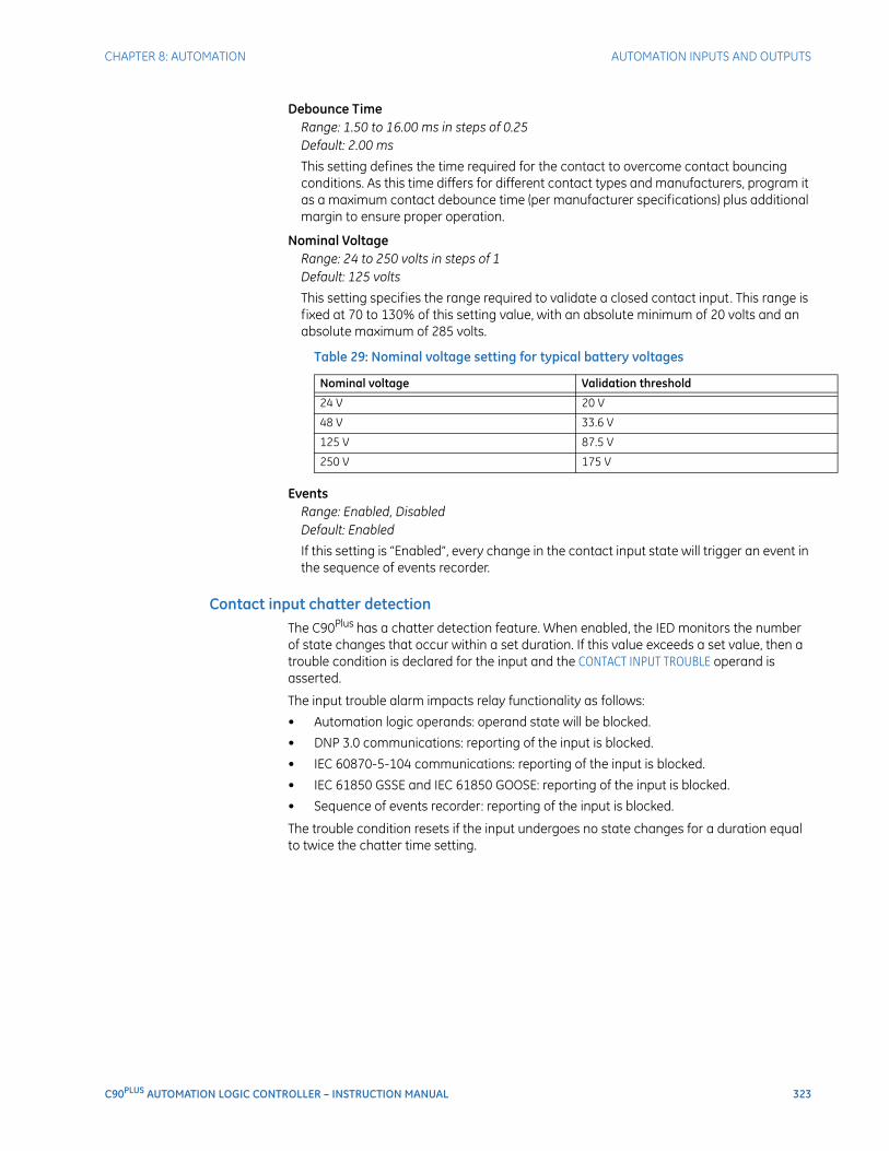
CHAPTER 8: AUTOMATION AUTOMATION INPUTS AND OUTPUTS
C90PLUS AUTOMATION LOGIC CONTROLLER – INSTRUCTION MANUAL 323
Debounce TimeRange: 1.50 to 16.00 ms in steps of 0.25Default: 2.00 ms
This setting defines the time required for the contact to overcome contact bouncing conditions. As this time differs for different contact types and manufacturers, program it as a maximum contact debounce time (per manufacturer specifications) plus additional margin to ensure proper operation.
Nominal VoltageRange: 24 to 250 volts in steps of 1Default: 125 volts
This setting specifies the range required to validate a closed contact input. This range is fixed at 70 to 130% of this setting value, with an absolute minimum of 20 volts and an absolute maximum of 285 volts.
Table 29: Nominal voltage setting for typical battery voltages
EventsRange: Enabled, DisabledDefault: Enabled
If this setting is “Enabled”, every change in the contact input state will trigger an event in the sequence of events recorder.
Contact input chatter detectionThe C90Plus has a chatter detection feature. When enabled, the IED monitors the number of state changes that occur within a set duration. If this value exceeds a set value, then a trouble condition is declared for the input and the CONTACT INPUT TROUBLE operand is asserted.
The input trouble alarm impacts relay functionality as follows:
• Automation logic operands: operand state will be blocked.
• DNP 3.0 communications: reporting of the input is blocked.
• IEC 60870-5-104 communications: reporting of the input is blocked.
• IEC 61850 GSSE and IEC 61850 GOOSE: reporting of the input is blocked.
• Sequence of events recorder: reporting of the input is blocked.
The trouble condition resets if the input undergoes no state changes for a duration equal to twice the chatter time setting.
Nominal voltage Validation threshold
24 V 20 V
48 V 33.6 V
125 V 87.5 V
250 V 175 V
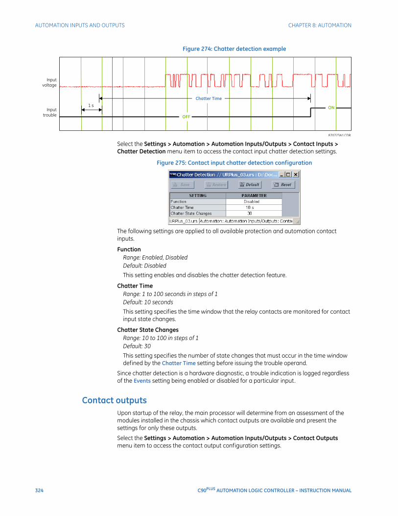
324 C90PLUS AUTOMATION LOGIC CONTROLLER – INSTRUCTION MANUAL
AUTOMATION INPUTS AND OUTPUTS CHAPTER 8: AUTOMATION
Figure 274: Chatter detection example
Select the Settings > Automation > Automation Inputs/Outputs > Contact Inputs > Chatter Detection menu item to access the contact input chatter detection settings.
Figure 275: Contact input chatter detection configuration
The following settings are applied to all available protection and automation contact inputs.
FunctionRange: Enabled, DisabledDefault: Disabled
This setting enables and disables the chatter detection feature.
Chatter TimeRange: 1 to 100 seconds in steps of 1Default: 10 seconds
This setting specifies the time window that the relay contacts are monitored for contact input state changes.
Chatter State ChangesRange: 10 to 100 in steps of 1Default: 30
This setting specifies the number of state changes that must occur in the time window defined by the Chatter Time setting before issuing the trouble operand.
Since chatter detection is a hardware diagnostic, a trouble indication is logged regardless of the Events setting being enabled or disabled for a particular input.
Contact outputsUpon startup of the relay, the main processor will determine from an assessment of the modules installed in the chassis which contact outputs are available and present the settings for only these outputs.
Select the Settings > Automation > Automation Inputs/Outputs > Contact Outputs menu item to access the contact output configuration settings.
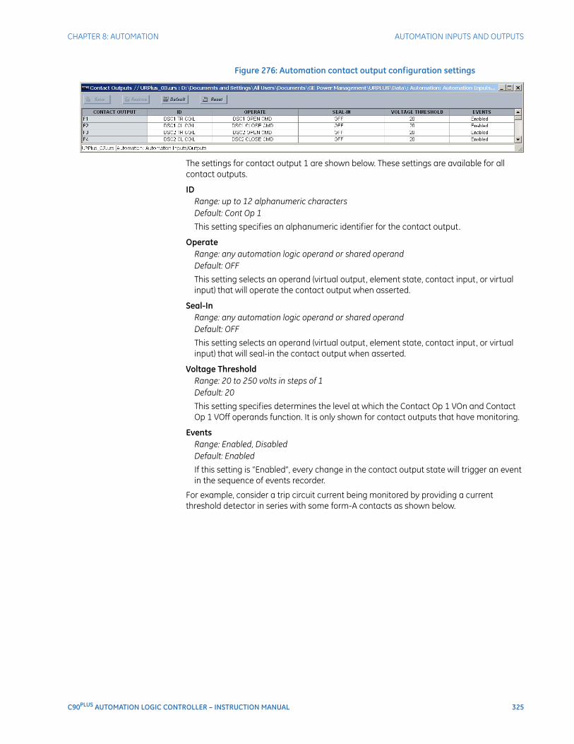
CHAPTER 8: AUTOMATION AUTOMATION INPUTS AND OUTPUTS
C90PLUS AUTOMATION LOGIC CONTROLLER – INSTRUCTION MANUAL 325
Figure 276: Automation contact output configuration settings
The settings for contact output 1 are shown below. These settings are available for all contact outputs.
IDRange: up to 12 alphanumeric charactersDefault: Cont Op 1
This setting specifies an alphanumeric identifier for the contact output.
OperateRange: any automation logic operand or shared operandDefault: OFF
This setting selects an operand (virtual output, element state, contact input, or virtual input) that will operate the contact output when asserted.
Seal-InRange: any automation logic operand or shared operandDefault: OFF
This setting selects an operand (virtual output, element state, contact input, or virtual input) that will seal-in the contact output when asserted.
Voltage ThresholdRange: 20 to 250 volts in steps of 1Default: 20
This setting specifies determines the level at which the Contact Op 1 VOn and Contact Op 1 VOff operands function. It is only shown for contact outputs that have monitoring.
EventsRange: Enabled, DisabledDefault: Enabled
If this setting is “Enabled”, every change in the contact output state will trigger an event in the sequence of events recorder.
For example, consider a trip circuit current being monitored by providing a current threshold detector in series with some form-A contacts as shown below.
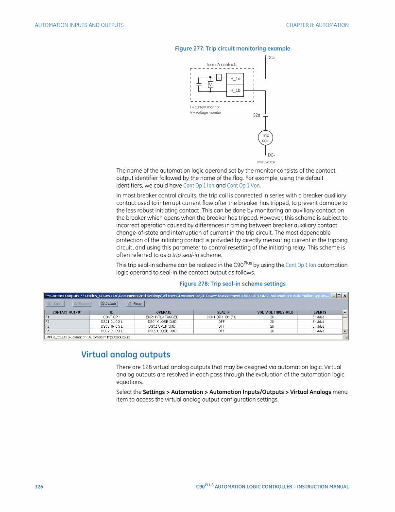
326 C90PLUS AUTOMATION LOGIC CONTROLLER – INSTRUCTION MANUAL
AUTOMATION INPUTS AND OUTPUTS CHAPTER 8: AUTOMATION
Figure 277: Trip circuit monitoring example
The name of the automation logic operand set by the monitor consists of the contact output identifier followed by the name of the flag. For example, using the default identifiers, we could have Cont Op 1 Ion and Cont Op 1 Von.
In most breaker control circuits, the trip coil is connected in series with a breaker auxiliary contact used to interrupt current flow after the breaker has tripped, to prevent damage to the less robust initiating contact. This can be done by monitoring an auxiliary contact on the breaker which opens when the breaker has tripped. However, this scheme is subject to incorrect operation caused by differences in timing between breaker auxiliary contact change-of-state and interruption of current in the trip circuit. The most dependable protection of the initiating contact is provided by directly measuring current in the tripping circuit, and using this parameter to control resetting of the initiating relay. This scheme is often referred to as a trip seal-in scheme.
This trip seal-in scheme can be realized in the C90Plus by using the Cont Op 1 Ion automation logic operand to seal-in the contact output as follows.
Figure 278: Trip seal-in scheme settings
Virtual analog outputsThere are 128 virtual analog outputs that may be assigned via automation logic. Virtual analog outputs are resolved in each pass through the evaluation of the automation logic equations.
Select the Settings > Automation > Automation Inputs/Outputs > Virtual Analogs menu item to access the virtual analog output configuration settings.
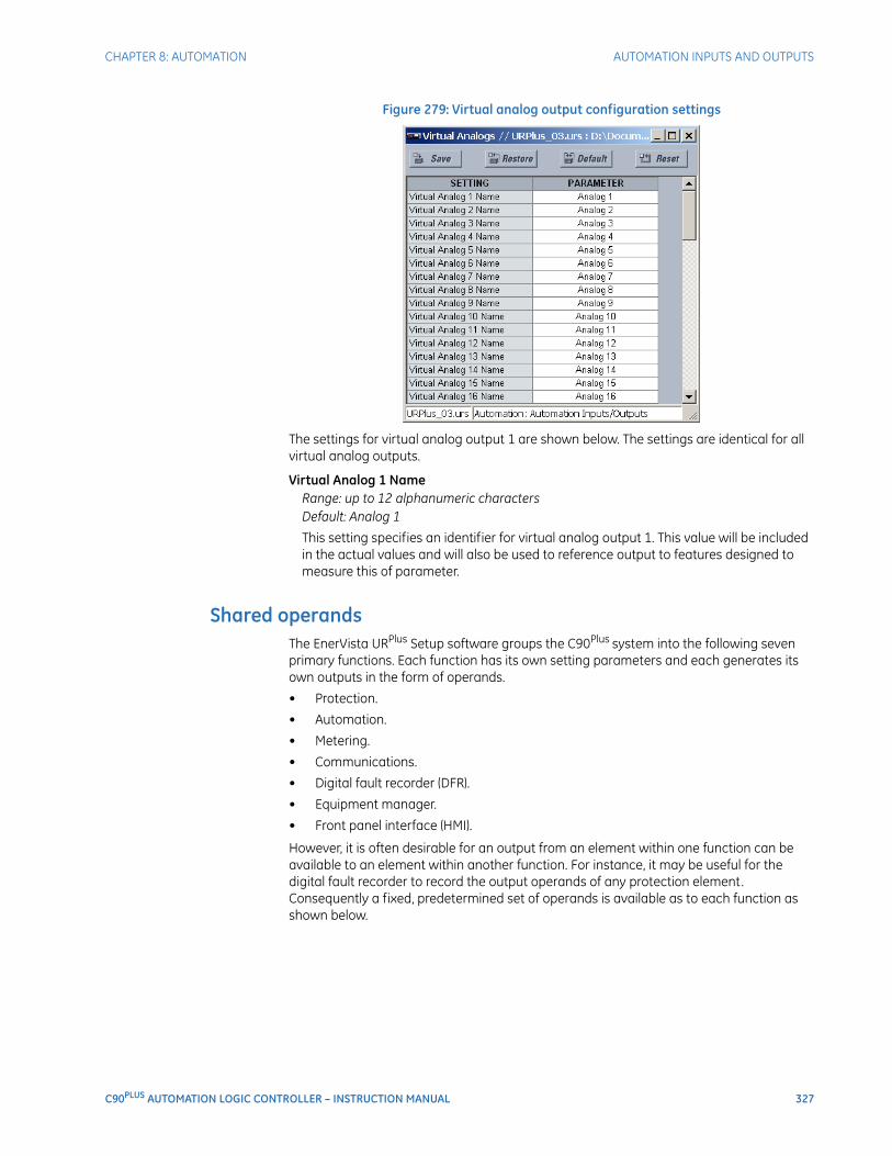
CHAPTER 8: AUTOMATION AUTOMATION INPUTS AND OUTPUTS
C90PLUS AUTOMATION LOGIC CONTROLLER – INSTRUCTION MANUAL 327
Figure 279: Virtual analog output configuration settings
The settings for virtual analog output 1 are shown below. The settings are identical for all virtual analog outputs.
Virtual Analog 1 NameRange: up to 12 alphanumeric charactersDefault: Analog 1
This setting specifies an identifier for virtual analog output 1. This value will be included in the actual values and will also be used to reference output to features designed to measure this of parameter.
Shared operandsThe EnerVista URPlus Setup software groups the C90Plus system into the following seven primary functions. Each function has its own setting parameters and each generates its own outputs in the form of operands.
• Protection.
• Automation.
• Metering.
• Communications.
• Digital fault recorder (DFR).
• Equipment manager.
• Front panel interface (HMI).
However, it is often desirable for an output from an element within one function can be available to an element within another function. For instance, it may be useful for the digital fault recorder to record the output operands of any protection element. Consequently a fixed, predetermined set of operands is available as to each function as shown below.
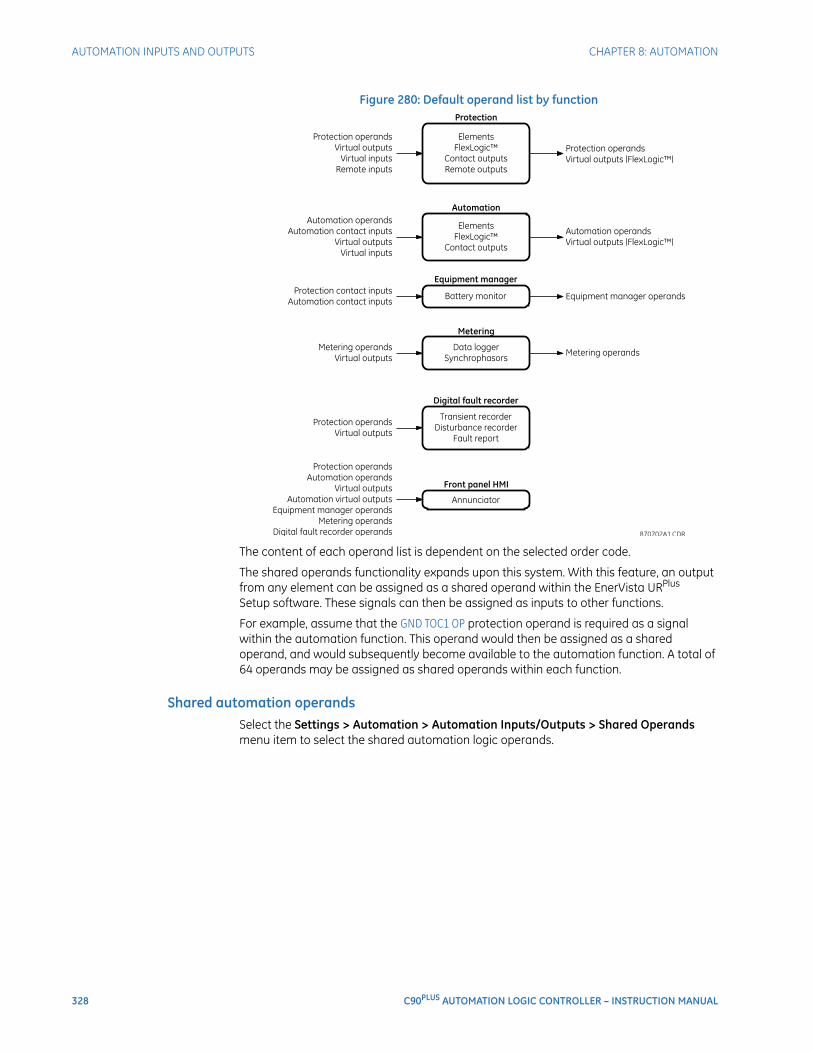
328 C90PLUS AUTOMATION LOGIC CONTROLLER – INSTRUCTION MANUAL
AUTOMATION INPUTS AND OUTPUTS CHAPTER 8: AUTOMATION
Figure 280: Default operand list by function
The content of each operand list is dependent on the selected order code.
The shared operands functionality expands upon this system. With this feature, an output from any element can be assigned as a shared operand within the EnerVista URPlus Setup software. These signals can then be assigned as inputs to other functions.
For example, assume that the GND TOC1 OP protection operand is required as a signal within the automation function. This operand would then be assigned as a shared operand, and would subsequently become available to the automation function. A total of 64 operands may be assigned as shared operands within each function.
Shared automation operandsSelect the Settings > Automation > Automation Inputs/Outputs > Shared Operands menu item to select the shared automation logic operands.
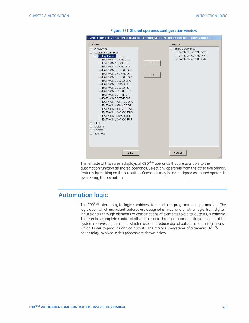
CHAPTER 8: AUTOMATION AUTOMATION LOGIC
C90PLUS AUTOMATION LOGIC CONTROLLER – INSTRUCTION MANUAL 329
Figure 281: Shared operands configuration window
The left side of this screen displays all C90Plus operands that are available to the automation function as shared operands. Select any operands from the other five primary features by clicking on the >> button. Operands may be de-assigned as shared operands by pressing the << button.
Automation logicThe C90Plus internal digital logic combines fixed and user-programmable parameters. The logic upon which individual features are designed is fixed, and all other logic, from digital input signals through elements or combinations of elements to digital outputs, is variable. The user has complete control of all variable logic through automation logic. In general, the system receives digital inputs which it uses to produce digital outputs and analog inputs which it uses to produce analog outputs. The major sub-systems of a generic URPlus-series relay involved in this process are shown below.
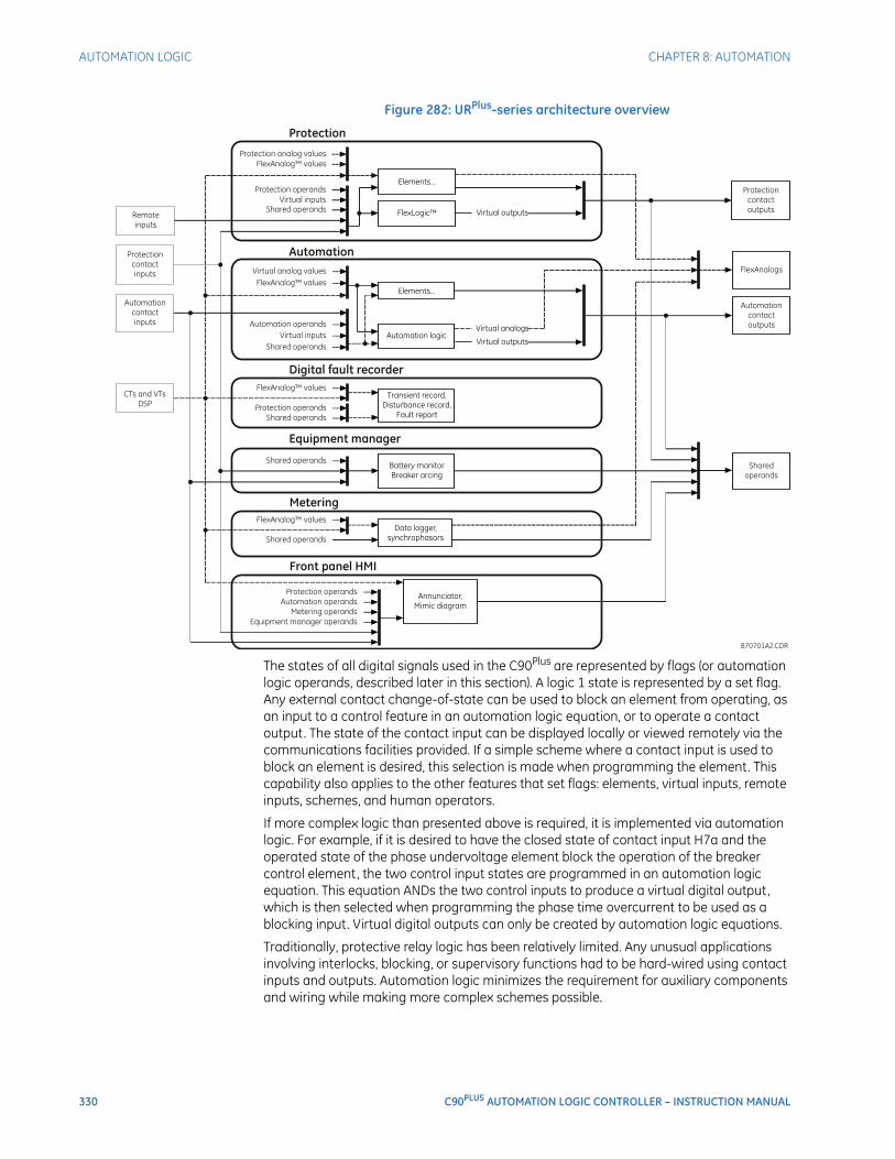
330 C90PLUS AUTOMATION LOGIC CONTROLLER – INSTRUCTION MANUAL
AUTOMATION LOGIC CHAPTER 8: AUTOMATION
Figure 282: URPlus-series architecture overview
The states of all digital signals used in the C90Plus are represented by flags (or automation logic operands, described later in this section). A logic 1 state is represented by a set flag. Any external contact change-of-state can be used to block an element from operating, as an input to a control feature in an automation logic equation, or to operate a contact output. The state of the contact input can be displayed locally or viewed remotely via the communications facilities provided. If a simple scheme where a contact input is used to block an element is desired, this selection is made when programming the element. This capability also applies to the other features that set flags: elements, virtual inputs, remote inputs, schemes, and human operators.
If more complex logic than presented above is required, it is implemented via automation logic. For example, if it is desired to have the closed state of contact input H7a and the operated state of the phase undervoltage element block the operation of the breaker control element, the two control input states are programmed in an automation logic equation. This equation ANDs the two control inputs to produce a virtual digital output, which is then selected when programming the phase time overcurrent to be used as a blocking input. Virtual digital outputs can only be created by automation logic equations.
Traditionally, protective relay logic has been relatively limited. Any unusual applications involving interlocks, blocking, or supervisory functions had to be hard-wired using contact inputs and outputs. Automation logic minimizes the requirement for auxiliary components and wiring while making more complex schemes possible.
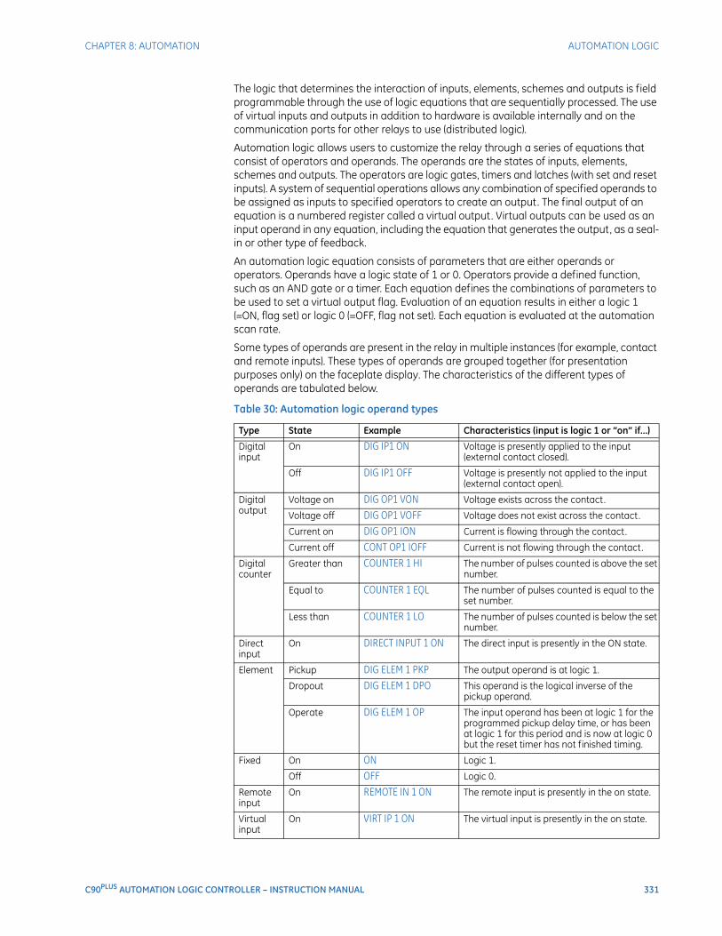
CHAPTER 8: AUTOMATION AUTOMATION LOGIC
C90PLUS AUTOMATION LOGIC CONTROLLER – INSTRUCTION MANUAL 331
The logic that determines the interaction of inputs, elements, schemes and outputs is field programmable through the use of logic equations that are sequentially processed. The use of virtual inputs and outputs in addition to hardware is available internally and on the communication ports for other relays to use (distributed logic).
Automation logic allows users to customize the relay through a series of equations that consist of operators and operands. The operands are the states of inputs, elements, schemes and outputs. The operators are logic gates, timers and latches (with set and reset inputs). A system of sequential operations allows any combination of specified operands to be assigned as inputs to specified operators to create an output. The final output of an equation is a numbered register called a virtual output. Virtual outputs can be used as an input operand in any equation, including the equation that generates the output, as a seal-in or other type of feedback.
An automation logic equation consists of parameters that are either operands or operators. Operands have a logic state of 1 or 0. Operators provide a defined function, such as an AND gate or a timer. Each equation defines the combinations of parameters to be used to set a virtual output flag. Evaluation of an equation results in either a logic 1 (=ON, flag set) or logic 0 (=OFF, flag not set). Each equation is evaluated at the automation scan rate.
Some types of operands are present in the relay in multiple instances (for example, contact and remote inputs). These types of operands are grouped together (for presentation purposes only) on the faceplate display. The characteristics of the different types of operands are tabulated below.
Table 30: Automation logic operand types
Type State Example Characteristics (input is logic 1 or “on” if...)
Digital input
On DIG IP1 ON Voltage is presently applied to the input (external contact closed).
Off DIG IP1 OFF Voltage is presently not applied to the input (external contact open).
Digital output
Voltage on DIG OP1 VON Voltage exists across the contact.
Voltage off DIG OP1 VOFF Voltage does not exist across the contact.
Current on DIG OP1 ION Current is flowing through the contact.
Current off CONT OP1 IOFF Current is not flowing through the contact.
Digital counter
Greater than COUNTER 1 HI The number of pulses counted is above the set number.
Equal to COUNTER 1 EQL The number of pulses counted is equal to the set number.
Less than COUNTER 1 LO The number of pulses counted is below the set number.
Direct input
On DIRECT INPUT 1 ON The direct input is presently in the ON state.
Element Pickup DIG ELEM 1 PKP The output operand is at logic 1.
Dropout DIG ELEM 1 DPO This operand is the logical inverse of the pickup operand.
Operate DIG ELEM 1 OP The input operand has been at logic 1 for the programmed pickup delay time, or has been at logic 1 for this period and is now at logic 0 but the reset timer has not finished timing.
Fixed On ON Logic 1.
Off OFF Logic 0.
Remote input
On REMOTE IN 1 ON The remote input is presently in the on state.
Virtual input
On VIRT IP 1 ON The virtual input is presently in the on state.
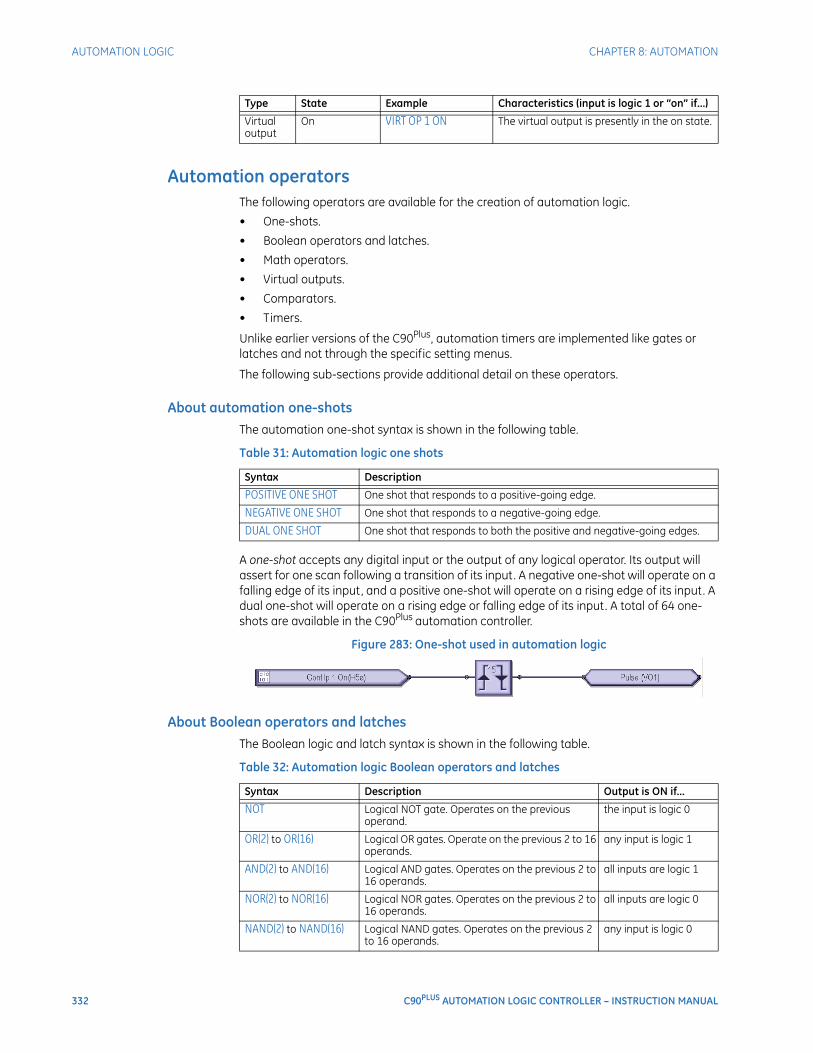
332 C90PLUS AUTOMATION LOGIC CONTROLLER – INSTRUCTION MANUAL
AUTOMATION LOGIC CHAPTER 8: AUTOMATION
Automation operatorsThe following operators are available for the creation of automation logic.
• One-shots.
• Boolean operators and latches.
• Math operators.
• Virtual outputs.
• Comparators.
• Timers.
Unlike earlier versions of the C90Plus, automation timers are implemented like gates or latches and not through the specific setting menus.
The following sub-sections provide additional detail on these operators.
About automation one-shotsThe automation one-shot syntax is shown in the following table.
Table 31: Automation logic one shots
A one-shot accepts any digital input or the output of any logical operator. Its output will assert for one scan following a transition of its input. A negative one-shot will operate on a falling edge of its input, and a positive one-shot will operate on a rising edge of its input. A dual one-shot will operate on a rising edge or falling edge of its input. A total of 64 one-shots are available in the C90Plus automation controller.
Figure 283: One-shot used in automation logic
About Boolean operators and latchesThe Boolean logic and latch syntax is shown in the following table.
Table 32: Automation logic Boolean operators and latches
Virtual output
On VIRT OP 1 ON The virtual output is presently in the on state.
Type State Example Characteristics (input is logic 1 or “on” if...)
Syntax Description
POSITIVE ONE SHOT One shot that responds to a positive-going edge.
NEGATIVE ONE SHOT One shot that responds to a negative-going edge.
DUAL ONE SHOT One shot that responds to both the positive and negative-going edges.
Syntax Description Output is ON if...
NOT Logical NOT gate. Operates on the previous operand.
the input is logic 0
OR(2) to OR(16) Logical OR gates. Operate on the previous 2 to 16 operands.
any input is logic 1
AND(2) to AND(16) Logical AND gates. Operates on the previous 2 to 16 operands.
all inputs are logic 1
NOR(2) to NOR(16) Logical NOR gates. Operates on the previous 2 to 16 operands.
all inputs are logic 0
NAND(2) to NAND(16) Logical NAND gates. Operates on the previous 2 to 16 operands.
any input is logic 0
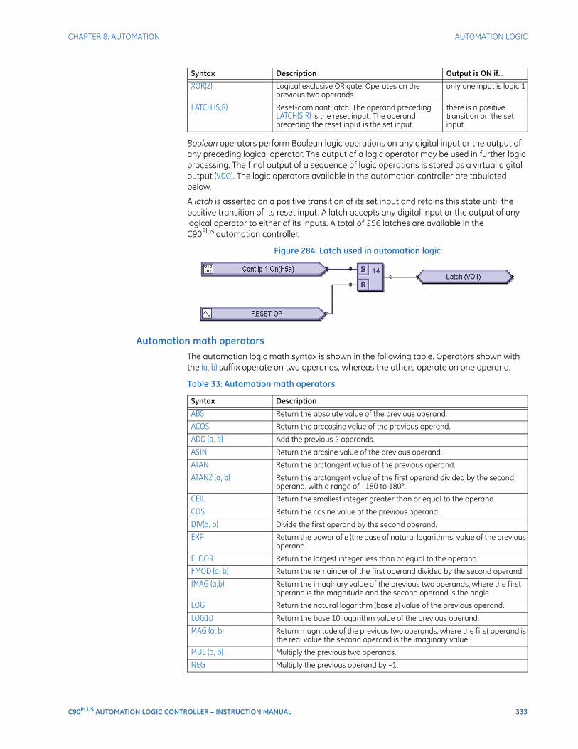
CHAPTER 8: AUTOMATION AUTOMATION LOGIC
C90PLUS AUTOMATION LOGIC CONTROLLER – INSTRUCTION MANUAL 333
Boolean operators perform Boolean logic operations on any digital input or the output of any preceding logical operator. The output of a logic operator may be used in further logic processing. The final output of a sequence of logic operations is stored as a virtual digital output (VDO). The logic operators available in the automation controller are tabulated below.
A latch is asserted on a positive transition of its set input and retains this state until the positive transition of its reset input. A latch accepts any digital input or the output of any logical operator to either of its inputs. A total of 256 latches are available in the C90Plus automation controller.
Figure 284: Latch used in automation logic
Automation math operatorsThe automation logic math syntax is shown in the following table. Operators shown with the (a, b) suffix operate on two operands, whereas the others operate on one operand.
Table 33: Automation math operators
XOR(2) Logical exclusive OR gate. Operates on the previous two operands.
only one input is logic 1
LATCH (S,R) Reset-dominant latch. The operand preceding LATCH(S,R) is the reset input. The operand preceding the reset input is the set input.
there is a positive transition on the set input
Syntax Description Output is ON if...
Syntax Description
ABS Return the absolute value of the previous operand.
ACOS Return the arccosine value of the previous operand.
ADD (a, b) Add the previous 2 operands.
ASIN Return the arcsine value of the previous operand.
ATAN Return the arctangent value of the previous operand.
ATAN2 (a, b) Return the arctangent value of the first operand divided by the second operand, with a range of –180 to 180°.
CEIL Return the smallest integer greater than or equal to the operand.
COS Return the cosine value of the previous operand.
DIV(a, b) Divide the first operand by the second operand.
EXP Return the power of e (the base of natural logarithms) value of the previous operand.
FLOOR Return the largest integer less than or equal to the operand.
FMOD (a, b) Return the remainder of the first operand divided by the second operand.
IMAG (a,b) Return the imaginary value of the previous two operands, where the first operand is the magnitude and the second operand is the angle.
LOG Return the natural logarithm (base e) value of the previous operand.
LOG10 Return the base 10 logarithm value of the previous operand.
MAG (a, b) Return magnitude of the previous two operands, where the first operand is the real value the second operand is the imaginary value.
MUL (a, b) Multiply the previous two operands.
NEG Multiply the previous operand by –1.
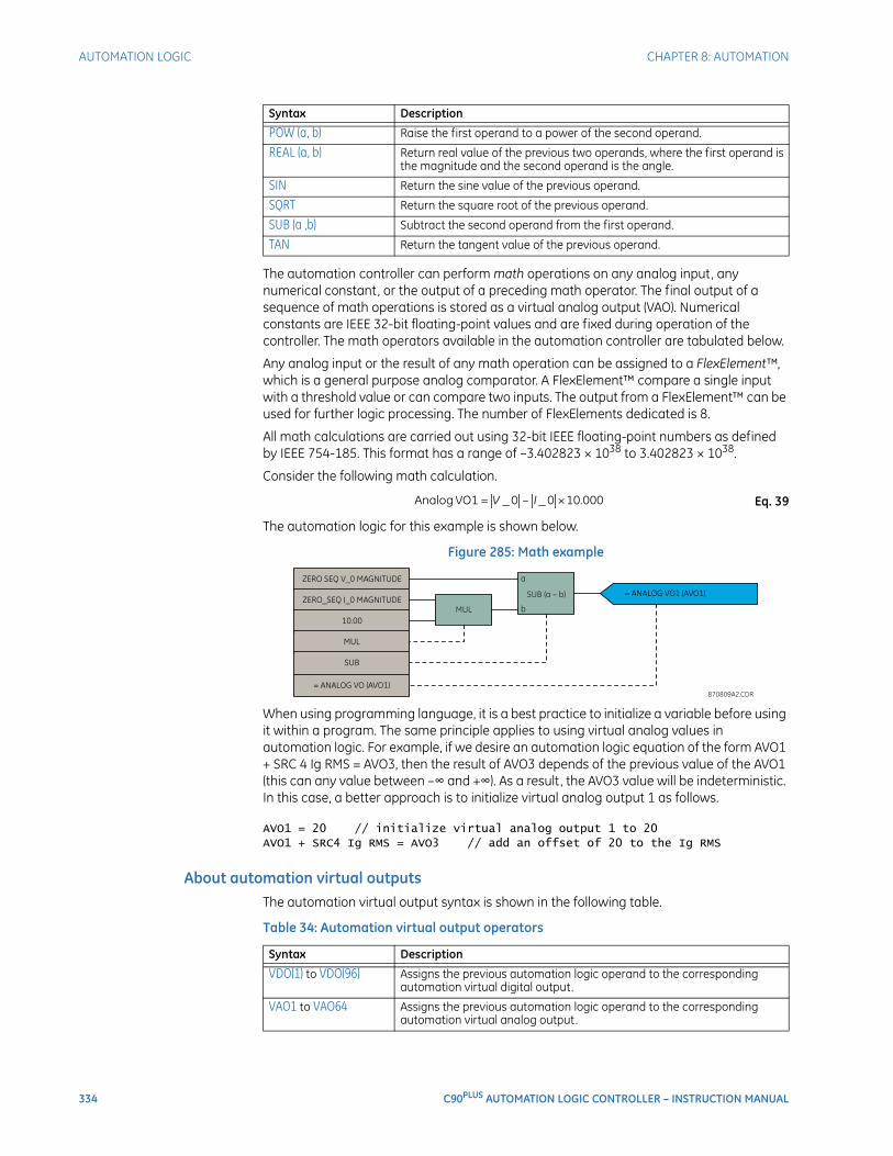
334 C90PLUS AUTOMATION LOGIC CONTROLLER – INSTRUCTION MANUAL
AUTOMATION LOGIC CHAPTER 8: AUTOMATION
The automation controller can perform math operations on any analog input, any numerical constant, or the output of a preceding math operator. The final output of a sequence of math operations is stored as a virtual analog output (VAO). Numerical constants are IEEE 32-bit floating-point values and are fixed during operation of the controller. The math operators available in the automation controller are tabulated below.
Any analog input or the result of any math operation can be assigned to a FlexElement™, which is a general purpose analog comparator. A FlexElement™ compare a single input with a threshold value or can compare two inputs. The output from a FlexElement™ can be used for further logic processing. The number of FlexElements dedicated is 8.
All math calculations are carried out using 32-bit IEEE floating-point numbers as defined by IEEE 754-185. This format has a range of –3.402823 × 1038 to 3.402823 × 1038.
Consider the following math calculation.
Eq. 39
The automation logic for this example is shown below.
Figure 285: Math example
When using programming language, it is a best practice to initialize a variable before using it within a program. The same principle applies to using virtual analog values in automation logic. For example, if we desire an automation logic equation of the form AVO1 + SRC 4 Ig RMS = AVO3, then the result of AVO3 depends of the previous value of the AVO1 (this can any value between –∞ and +∞). As a result, the AVO3 value will be indeterministic. In this case, a better approach is to initialize virtual analog output 1 as follows.
AVO1 = 20 // initialize virtual analog output 1 to 20 AVO1 + SRC4 Ig RMS = AVO3 // add an offset of 20 to the Ig RMS
About automation virtual outputsThe automation virtual output syntax is shown in the following table.
Table 34: Automation virtual output operators
POW (a, b) Raise the first operand to a power of the second operand.
REAL (a, b) Return real value of the previous two operands, where the first operand is the magnitude and the second operand is the angle.
SIN Return the sine value of the previous operand.
SQRT Return the square root of the previous operand.
SUB (a ,b) Subtract the second operand from the first operand.
TAN Return the tangent value of the previous operand.
Syntax Description
Syntax Description
VDO(1) to VDO(96) Assigns the previous automation logic operand to the corresponding automation virtual digital output.
VAO1 to VAO64 Assigns the previous automation logic operand to the corresponding automation virtual analog output.
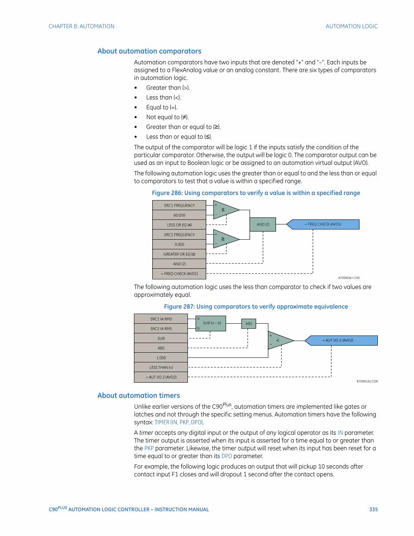
CHAPTER 8: AUTOMATION AUTOMATION LOGIC
C90PLUS AUTOMATION LOGIC CONTROLLER – INSTRUCTION MANUAL 335
About automation comparatorsAutomation comparators have two inputs that are denoted "+" and "–". Each inputs be assigned to a FlexAnalog value or an analog constant. There are six types of comparators in automation logic.
• Greater than (>).
• Less than (<).
• Equal to (=).
• Not equal to (≠).
• Greater than or equal to (≥).
• Less than or equal to (≤).
The output of the comparator will be logic 1 if the inputs satisfy the condition of the particular comparator. Otherwise, the output will be logic 0. The comparator output can be used as an input to Boolean logic or be assigned to an automation virtual output (AVO).
The following automation logic uses the greater than or equal to and the less than or equal to comparators to test that a value is within a specified range.
Figure 286: Using comparators to verify a value is within a specified range
The following automation logic uses the less than comparator to check if two values are approximately equal.
Figure 287: Using comparators to verify approximate equivalence
About automation timersUnlike earlier versions of the C90Plus, automation timers are implemented like gates or latches and not through the specific setting menus. Automation timers have the following syntax: TIMER (IN, PKP, DPO).
A timer accepts any digital input or the output of any logical operator as its IN parameter. The timer output is asserted when its input is asserted for a time equal to or greater than the PKP parameter. Likewise, the timer output will reset when its input has been reset for a time equal to or greater than its DPO parameter.
For example, the following logic produces an output that will pickup 10 seconds after contact input F1 closes and will dropout 1 second after the contact opens.
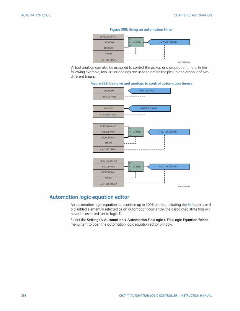
336 C90PLUS AUTOMATION LOGIC CONTROLLER – INSTRUCTION MANUAL
AUTOMATION LOGIC CHAPTER 8: AUTOMATION
Figure 288: Using an automation timer
Virtual analogs can also be assigned to control the pickup and dropout of timers. In the following example, two virtual analogs are used to define the pickup and dropout of two different timers.
Figure 289: Using virtual analogs to control automation timers
Automation logic equation editorAn automation logic equation can contain up to 4096 entries, including the END operator. If a disabled element is selected as an automation logic entry, the associated state flag will never be asserted (set to logic 1).
Select the Settings > Automation > Automation FlexLogic > FlexLogic Equation Editor menu item to open the automation logic equation editor window.
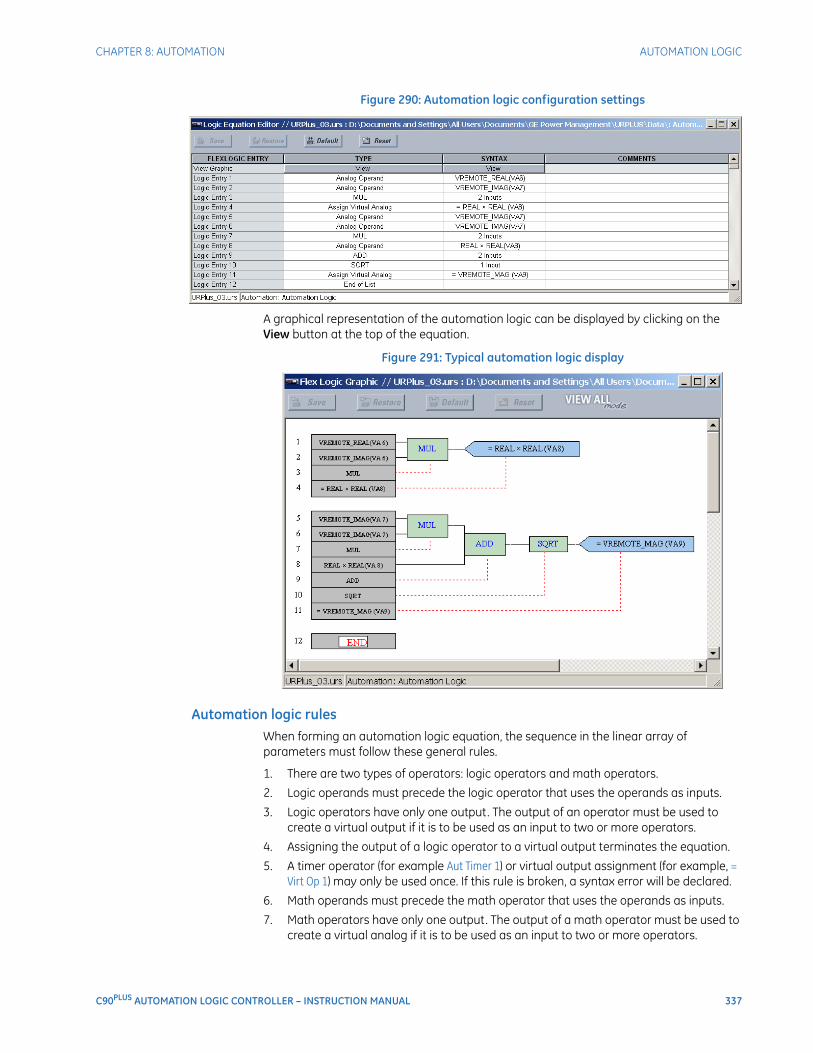
CHAPTER 8: AUTOMATION AUTOMATION LOGIC
C90PLUS AUTOMATION LOGIC CONTROLLER – INSTRUCTION MANUAL 337
Figure 290: Automation logic configuration settings
A graphical representation of the automation logic can be displayed by clicking on the View button at the top of the equation.
Figure 291: Typical automation logic display
Automation logic rulesWhen forming an automation logic equation, the sequence in the linear array of parameters must follow these general rules.
1. There are two types of operators: logic operators and math operators.
2. Logic operands must precede the logic operator that uses the operands as inputs.
3. Logic operators have only one output. The output of an operator must be used to create a virtual output if it is to be used as an input to two or more operators.
4. Assigning the output of a logic operator to a virtual output terminates the equation.
5. A timer operator (for example Aut Timer 1) or virtual output assignment (for example, = Virt Op 1) may only be used once. If this rule is broken, a syntax error will be declared.
6. Math operands must precede the math operator that uses the operands as inputs.
7. Math operators have only one output. The output of a math operator must be used to create a virtual analog if it is to be used as an input to two or more operators.
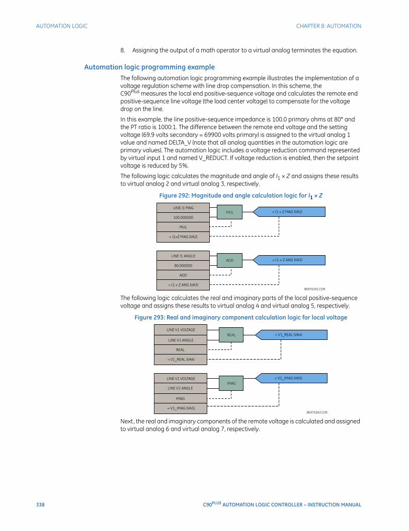
338 C90PLUS AUTOMATION LOGIC CONTROLLER – INSTRUCTION MANUAL
AUTOMATION LOGIC CHAPTER 8: AUTOMATION
8. Assigning the output of a math operator to a virtual analog terminates the equation.
Automation logic programming exampleThe following automation logic programming example illustrates the implementation of a voltage regulation scheme with line drop compensation. In this scheme, the C90Plus measures the local end positive-sequence voltage and calculates the remote end positive-sequence line voltage (the load center voltage) to compensate for the voltage drop on the line.
In this example, the line positive-sequence impedance is 100.0 primary ohms at 80° and the PT ratio is 1000:1. The difference between the remote end voltage and the setting voltage (69.9 volts secondary = 69900 volts primary) is assigned to the virtual analog 1 value and named DELTA_V (note that all analog quantities in the automation logic are primary values). The automation logic includes a voltage reduction command represented by virtual input 1 and named V_REDUCT. If voltage reduction is enabled, then the setpoint voltage is reduced by 5%.
The following logic calculates the magnitude and angle of I1 × Z and assigns these results to virtual analog 2 and virtual analog 3, respectively.
Figure 292: Magnitude and angle calculation logic for I1 × Z
The following logic calculates the real and imaginary parts of the local positive-sequence voltage and assigns these results to virtual analog 4 and virtual analog 5, respectively.
Figure 293: Real and imaginary component calculation logic for local voltage
Next, the real and imaginary components of the remote voltage is calculated and assigned to virtual analog 6 and virtual analog 7, respectively.
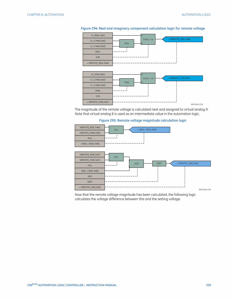
CHAPTER 8: AUTOMATION AUTOMATION LOGIC
C90PLUS AUTOMATION LOGIC CONTROLLER – INSTRUCTION MANUAL 339
Figure 294: Real and imaginary component calculation logic for remote voltage
The magnitude of the remote voltage is calculated next and assigned to virtual analog 9. Note that virtual analog 8 is used as an intermediate value in the automation logic.
Figure 295: Remote voltage magnitude calculation logic
Now that the remote voltage magnitude has been calculated, the following logic calculates the voltage difference between this and the setting voltage.
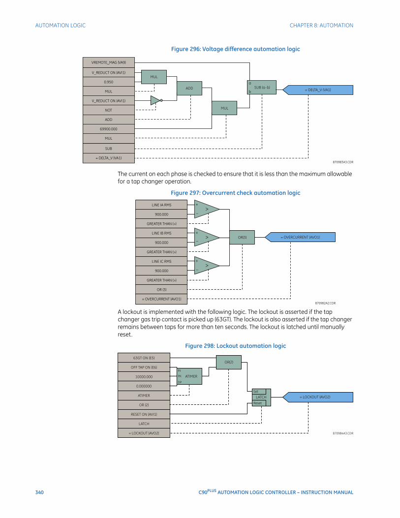
340 C90PLUS AUTOMATION LOGIC CONTROLLER – INSTRUCTION MANUAL
AUTOMATION LOGIC CHAPTER 8: AUTOMATION
Figure 296: Voltage difference automation logic
The current on each phase is checked to ensure that it is less than the maximum allowable for a tap changer operation.
Figure 297: Overcurrent check automation logic
A lockout is implemented with the following logic. The lockout is asserted if the tap changer gas trip contact is picked up (63GT). The lockout is also asserted if the tap changer remains between taps for more than ten seconds. The lockout is latched until manually reset.
Figure 298: Lockout automation logic
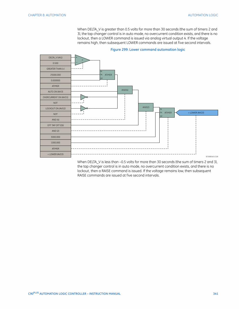
CHAPTER 8: AUTOMATION AUTOMATION LOGIC
C90PLUS AUTOMATION LOGIC CONTROLLER – INSTRUCTION MANUAL 341
When DELTA_V is greater than 0.5 volts for more than 30 seconds (the sum of timers 2 and 3), the tap changer control is in auto mode, no overcurrent condition exists, and there is no lockout, then a LOWER command is issued via analog virtual output 4. If the voltage remains high, then subsequent LOWER commands are issued at five second intervals.
Figure 299: Lower command automation logic
When DELTA_V is less than –0.5 volts for more than 30 seconds (the sum of timers 2 and 3), the tap changer control is in auto mode, no overcurrent condition exists, and there is no lockout, then a RAISE command is issued. If the voltage remains low, then subsequent RAISE commands are issued at five second intervals.
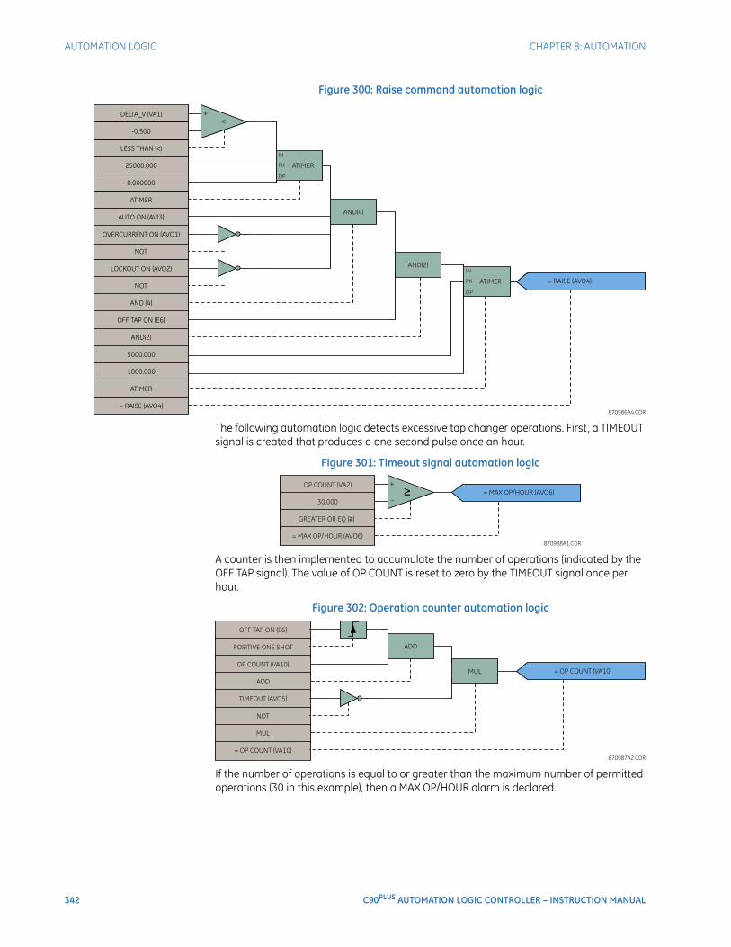
342 C90PLUS AUTOMATION LOGIC CONTROLLER – INSTRUCTION MANUAL
AUTOMATION LOGIC CHAPTER 8: AUTOMATION
Figure 300: Raise command automation logic
The following automation logic detects excessive tap changer operations. First, a TIMEOUT signal is created that produces a one second pulse once an hour.
Figure 301: Timeout signal automation logic
A counter is then implemented to accumulate the number of operations (indicated by the OFF TAP signal). The value of OP COUNT is reset to zero by the TIMEOUT signal once per hour.
Figure 302: Operation counter automation logic
If the number of operations is equal to or greater than the maximum number of permitted operations (30 in this example), then a MAX OP/HOUR alarm is declared.
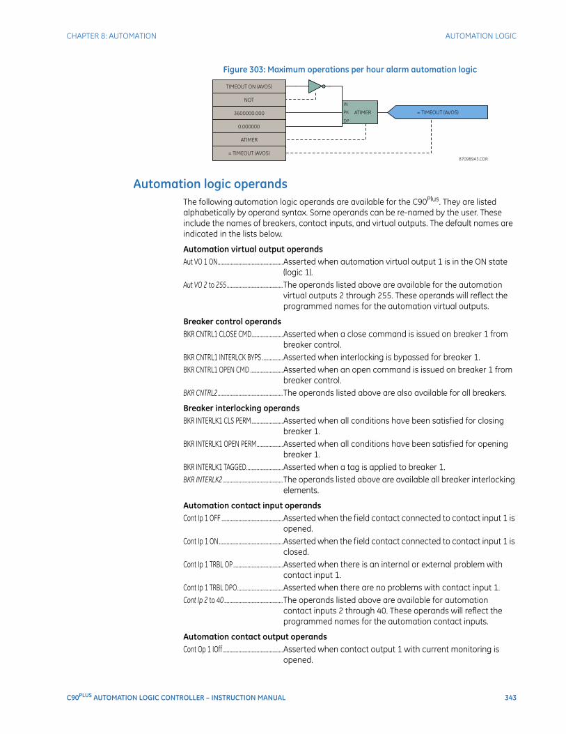
CHAPTER 8: AUTOMATION AUTOMATION LOGIC
C90PLUS AUTOMATION LOGIC CONTROLLER – INSTRUCTION MANUAL 343
Figure 303: Maximum operations per hour alarm automation logic
Automation logic operandsThe following automation logic operands are available for the C90Plus. They are listed alphabetically by operand syntax. Some operands can be re-named by the user. These include the names of breakers, contact inputs, and virtual outputs. The default names are indicated in the lists below.
Automation virtual output operandsAut VO 1 ON..................................................Asserted when automation virtual output 1 is in the ON state
(logic 1). Aut VO 2 to 255 ...........................................The operands listed above are available for the automation
virtual outputs 2 through 255. These operands will reflect the programmed names for the automation virtual outputs.
Breaker control operandsBKR CNTRL1 CLOSE CMD........................Asserted when a close command is issued on breaker 1 from
breaker control.BKR CNTRL1 INTERLCK BYPS ................Asserted when interlocking is bypassed for breaker 1.BKR CNTRL1 OPEN CMD .........................Asserted when an open command is issued on breaker 1 from
breaker control.BKR CNTRL2..................................................The operands listed above are also available for all breakers.
Breaker interlocking operandsBKR INTERLK1 CLS PERM........................Asserted when all conditions have been satisfied for closing
breaker 1.BKR INTERLK1 OPEN PERM....................Asserted when all conditions have been satisfied for opening
breaker 1.BKR INTERLK1 TAGGED............................Asserted when a tag is applied to breaker 1.BKR INTERLK2 ..............................................The operands listed above are available all breaker interlocking
elements.
Automation contact input operandsCont Ip 1 OFF ...............................................Asserted when the field contact connected to contact input 1 is
opened.Cont Ip 1 ON.................................................Asserted when the field contact connected to contact input 1 is
closed.Cont Ip 1 TRBL OP ......................................Asserted when there is an internal or external problem with
contact input 1.Cont Ip 1 TRBL DPO...................................Asserted when there are no problems with contact input 1.Cont Ip 2 to 40 .............................................The operands listed above are available for automation
contact inputs 2 through 40. These operands will reflect the programmed names for the automation contact inputs.
Automation contact output operandsCont Op 1 IOff ..............................................Asserted when contact output 1 with current monitoring is
opened.
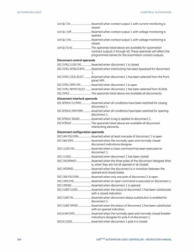
344 C90PLUS AUTOMATION LOGIC CONTROLLER – INSTRUCTION MANUAL
AUTOMATION LOGIC CHAPTER 8: AUTOMATION
Cont Op 1 IOn..............................................Asserted when contact output 1 with current monitoring is closed.
Cont Op 1 VOff ............................................Asserted when contact output 1 with voltage monitoring is opened.
Cont Op 1 VOn.............................................Asserted when contact output 1 with voltage monitoring is closed.
Cont Op 2 to 40........................................... The operands listed above are available for automation contract outputs 2 through 40. These operands will reflect the programmed names for the automation contact outputs.
Disconnect control operandsDISC CNTRL1 CLOSE CMD......................Asserted when disconnect 1 is closed.DISC CNTRL1 INTERLCK BYPS...............Asserted when interlocking has been bypassed for disconnect
1.DISC CNTRL1 LOCAL SELECT ................Asserted when disconnect 1 has been selected from the front
panel HMI.DISC CNTRL1 OPEN CMD........................Asserted when disconnect 1 is open.DISC CNTRL1 REMOTE SELECT.............Asserted when disconnect 1 has been selected from SCADA.DISC CNTRL2 ................................................ The operands listed above are available all disconnects.
Disconnect interlock operandsDISC INTERLK1 CLS PERM ......................Asserted when all conditions have been satisfied for closing
disconnect 1.DISC INTERLK1 OPEN PERM ..................Asserted when all conditions have been satisfied for opening
disconnect 1.DISC INTERLK1 TAGGED..........................Asserted when a tag is applied to disconnect 1.DISC INTERLK2 ............................................ The operands listed above are available all disconnect
interlocking elements.
Disconnect configuration operandsDISC1 ANY POLE OPEN............................Asserted when at least one pole of disconnect 1 is open.DISC1 BAD STATE .......................................Asserted when the normally open and normally closed
disconnect indications disagree.DISC1 CLOSE CMD.....................................Asserted when a close command has been executed on
disconnect 1.DISC1 CLOSED.............................................Asserted when disconnect 1 has been closed.DISC1 DISCREPANCY ................................Asserted when the three poles of the disconnect disagree (that
is, when they are not all opened or all closed).DISC1 INTERMED........................................Asserted when the disconnect is in transition between the
opened and closed states.DISC1 ONE POLE OPEN ...........................Asserted when only one pole of disconnect 1 is openDISC1 OPEN CMD.......................................Asserted when an open command is executed on disconnect 1.DISC1 OPENED ............................................Asserted when disconnect 1 is opened.DISC1 SUBST CLOSED ..............................Asserted when the status of disconnect 1 has been substituted
with a closed indication.DISC1 SUBST ON ........................................Asserted when disconnect status substitution is enabled for
disconnect 1.DISC1 SUBST OPENED .............................Asserted when the status of disconnect 1 has been substituted
with an opened indication.DISC1A BAD STATE.....................................Asserted when the normally open and normally closed breaker
indications disagree for pole A of disconnect 1.DISC1A CLOSED..........................................Asserted when disconnect 1 pole A is closed.
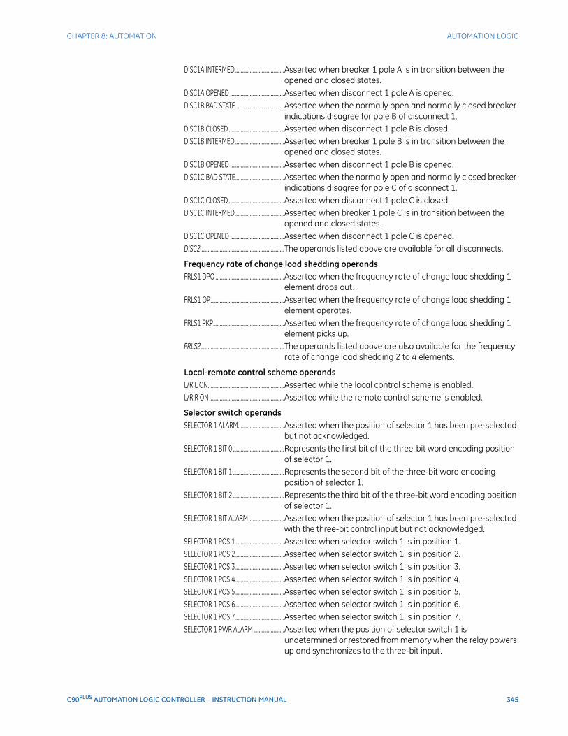
CHAPTER 8: AUTOMATION AUTOMATION LOGIC
C90PLUS AUTOMATION LOGIC CONTROLLER – INSTRUCTION MANUAL 345
DISC1A INTERMED .....................................Asserted when breaker 1 pole A is in transition between the opened and closed states.
DISC1A OPENED .........................................Asserted when disconnect 1 pole A is opened.DISC1B BAD STATE.....................................Asserted when the normally open and normally closed breaker
indications disagree for pole B of disconnect 1.DISC1B CLOSED ..........................................Asserted when disconnect 1 pole B is closed.DISC1B INTERMED .....................................Asserted when breaker 1 pole B is in transition between the
opened and closed states.DISC1B OPENED .........................................Asserted when disconnect 1 pole B is opened.DISC1C BAD STATE.....................................Asserted when the normally open and normally closed breaker
indications disagree for pole C of disconnect 1.DISC1C CLOSED ..........................................Asserted when disconnect 1 pole C is closed.DISC1C INTERMED .....................................Asserted when breaker 1 pole C is in transition between the
opened and closed states.DISC1C OPENED .........................................Asserted when disconnect 1 pole C is opened.DISC2 ...............................................................The operands listed above are available for all disconnects.
Frequency rate of change load shedding operandsFRLS1 DPO ....................................................Asserted when the frequency rate of change load shedding 1
element drops out.FRLS1 OP........................................................Asserted when the frequency rate of change load shedding 1
element operates.FRLS1 PKP......................................................Asserted when the frequency rate of change load shedding 1
element picks up.FRLS2... ............................................................The operands listed above are also available for the frequency
rate of change load shedding 2 to 4 elements.
Local-remote control scheme operandsL/R L ON..........................................................Asserted while the local control scheme is enabled.L/R R ON.........................................................Asserted while the remote control scheme is enabled.
Selector switch operandsSELECTOR 1 ALARM...................................Asserted when the position of selector 1 has been pre-selected
but not acknowledged.SELECTOR 1 BIT 0 .......................................Represents the first bit of the three-bit word encoding position
of selector 1.SELECTOR 1 BIT 1 .......................................Represents the second bit of the three-bit word encoding
position of selector 1.SELECTOR 1 BIT 2 .......................................Represents the third bit of the three-bit word encoding position
of selector 1.SELECTOR 1 BIT ALARM...........................Asserted when the position of selector 1 has been pre-selected
with the three-bit control input but not acknowledged.SELECTOR 1 POS 1.....................................Asserted when selector switch 1 is in position 1.SELECTOR 1 POS 2.....................................Asserted when selector switch 1 is in position 2.SELECTOR 1 POS 3.....................................Asserted when selector switch 1 is in position 3.SELECTOR 1 POS 4.....................................Asserted when selector switch 1 is in position 4.SELECTOR 1 POS 5.....................................Asserted when selector switch 1 is in position 5.SELECTOR 1 POS 6.....................................Asserted when selector switch 1 is in position 6.SELECTOR 1 POS 7.....................................Asserted when selector switch 1 is in position 7.SELECTOR 1 PWR ALARM .......................Asserted when the position of selector switch 1 is
undetermined or restored from memory when the relay powers up and synchronizes to the three-bit input.
346 C90PLUS AUTOMATION LOGIC CONTROLLER – INSTRUCTION MANUAL
AUTOMATION LOGIC CHAPTER 8: AUTOMATION
SELECTOR 1 STP ALARM..........................Asserted when the position of selector 1 has been pre-selected with the stepping up control input but not acknowledged.
SELECTOR 2... ............................................... The same set of operands as shown above are available for selector switch 2.
Synchrocheck operandsSYNC 1 CLS DPO.........................................Asserted when the synchrocheck 1 close has dropped out.SYNC 1 CLS OP ............................................Asserted when the synchrocheck 1 close has operated.SYNC 1 DEAD S DPO.................................Asserted when the synchrocheck 1 dead source has dropped
out.SYNC 1 DEAD S OP ....................................Asserted when the synchrocheck 1 dead source has operated.SYNC 1 SYNC DPO .....................................Asserted when the synchrocheck 1 has dropped out while in
synchronization.SYNC 1 SYNC OP.........................................Asserted when the synchrocheck 1 has operated while in
synchronization.SYNC 1 V1 ABOVE MIN.............................Asserted when the synchrocheck 1 V1 value is above the
minimum live voltage.SYNC 1 V1 BELOW MAX ..........................Asserted when the synchrocheck 1 V1 value is below the
maximum dead voltage.SYNC 1 V2 ABOVE MIN.............................Asserted when the synchrocheck 1 V2 value is above the
minimum live voltage.SYNC 1 V2 BELOW MAX ..........................Asserted when the synchrocheck 1 V2 value is below the
maximum dead voltage.SYNC 2............................................................. The set of operands shown above are available for
synchrocheck 2.
Underfrequency load shedding operandsUFLS1 DPO....................................................Asserted when the underfrequency load shedding 1 element
drops out.UFLS1 OP .......................................................Asserted when the underfrequency load shedding 1 element
operates.UFLS1 PKP.....................................................Asserted when the underfrequency load shedding 1 element
picks up.UFLS2... ........................................................... The operands listed above are also available for the
underfrequency load shedding 2 to 6 elements.
Undervoltage load shedding operandsUVLS1 DPO ...................................................Asserted when the undervoltage load shedding 1 element
drops out.UVLS1 OP....................................................... Asserted when the undervoltage load shedding 1 element
operates.UVLS1 PKP..................................................... Asserted when the undervoltage load shedding 1 element picks
up.UVLS2... ........................................................... The operands listed above are also available for the
undervoltage load shedding 2 to 6 elements.
C90PLUS AUTOMATION LOGIC CONTROLLER – INSTRUCTION MANUAL 347
C90Plus Automation Logic Controller
Chapter 9: Equipment manager
Equipment manager
A program for equipment monitoring can result in extended equipment life, improved system reliability, and increased equipment availability. Furthermore, effective equipment monitoring allows maintenance to be targeted towards the equipment in the greatest need. The C90Plus provides a variety of measurements and alarms that can be used to monitor the condition of the DC battery.
Overview of the equipment managerThe C90Plus equipment manager is broken down into six functions according to the specific equipment sub-system.
• Breaker arcing.
• Breaker timing.
• Coil signature.
• Breaker insulation.
• Breaker auxiliaries.
• Battery monitor.
NOTE
NOTE: Only the battery monitor and breaker arcing features are supported in the current version of the C90Plus.
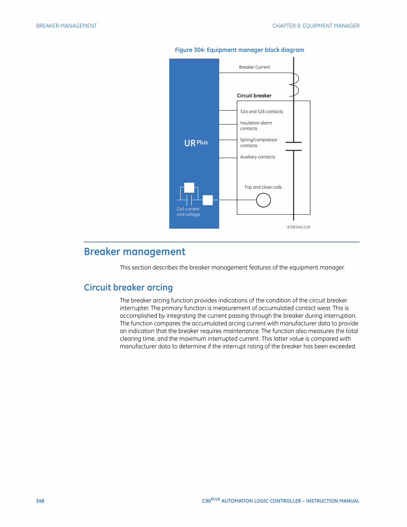
348 C90PLUS AUTOMATION LOGIC CONTROLLER – INSTRUCTION MANUAL
BREAKER MANAGEMENT CHAPTER 9: EQUIPMENT MANAGER
Figure 304: Equipment manager block diagram
Breaker managementThis section describes the breaker management features of the equipment manager.
Circuit breaker arcingThe breaker arcing function provides indications of the condition of the circuit breaker interrupter. The primary function is measurement of accumulated contact wear. This is accomplished by integrating the current passing through the breaker during interruption. The function compares the accumulated arcing current with manufacturer data to provide an indication that the breaker requires maintenance. The function also measures the total clearing time, and the maximum interrupted current. This latter value is compared with manufacturer data to determine if the interrupt rating of the breaker has been exceeded.
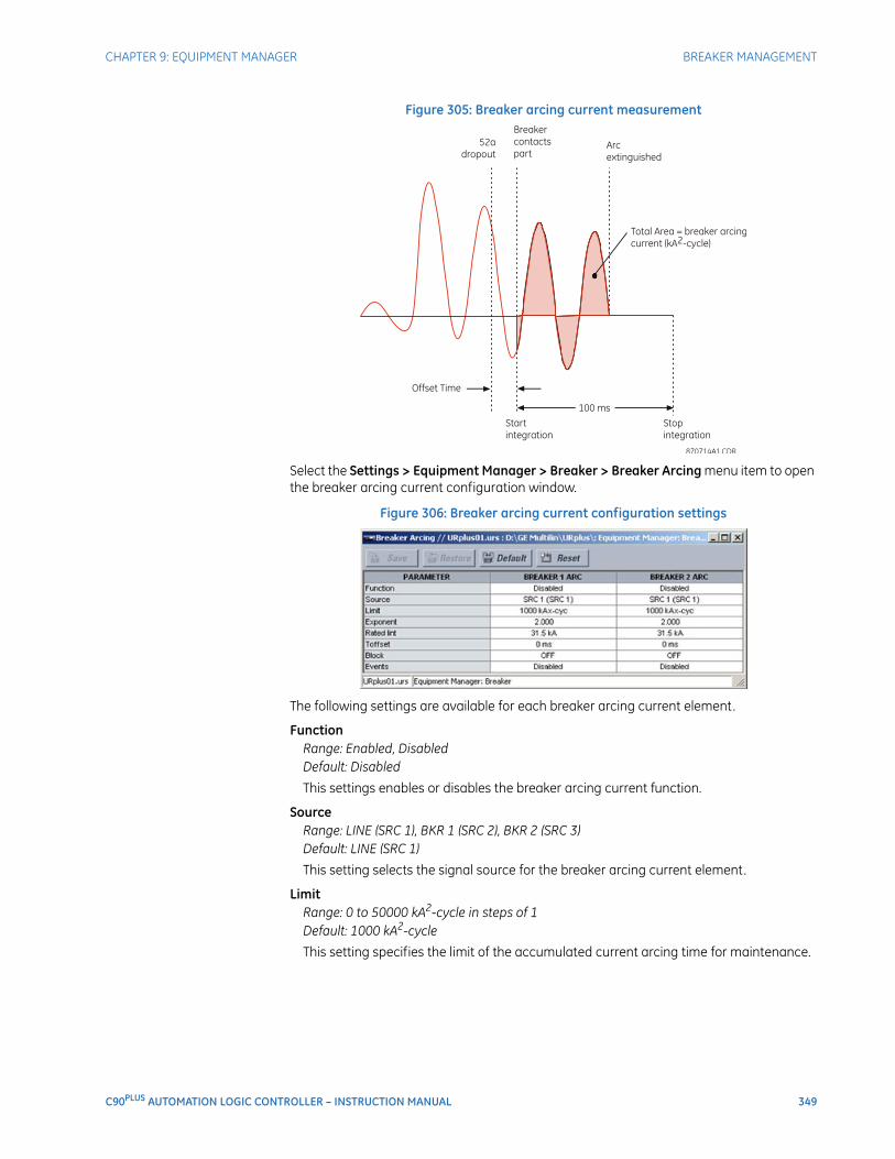
CHAPTER 9: EQUIPMENT MANAGER BREAKER MANAGEMENT
C90PLUS AUTOMATION LOGIC CONTROLLER – INSTRUCTION MANUAL 349
Figure 305: Breaker arcing current measurement
Select the Settings > Equipment Manager > Breaker > Breaker Arcing menu item to open the breaker arcing current configuration window.
Figure 306: Breaker arcing current configuration settings
The following settings are available for each breaker arcing current element.
FunctionRange: Enabled, DisabledDefault: Disabled
This settings enables or disables the breaker arcing current function.
SourceRange: LINE (SRC 1), BKR 1 (SRC 2), BKR 2 (SRC 3)Default: LINE (SRC 1)
This setting selects the signal source for the breaker arcing current element.
LimitRange: 0 to 50000 kA2-cycle in steps of 1Default: 1000 kA2-cycle
This setting specifies the limit of the accumulated current arcing time for maintenance.
350 C90PLUS AUTOMATION LOGIC CONTROLLER – INSTRUCTION MANUAL
BREAKER MANAGEMENT CHAPTER 9: EQUIPMENT MANAGER
ExponentRange: 1.000 to 5.000 in steps of 0.001Default: 2.000
This setting specifies the accumulated breaker wear is proportional to the following equation,
Eq. 40
where x is the arcing exponent. The typical value for the arcing exponent is 2.
Interruption RatingRange: 0.0 to 100.0 kA in steps of 0.1Default: 31.5 kA
This setting specifies the maximum symmetrical interruption rating of the circuit breaker.
Arcing Time OffsetRange: 0 to 50 ms in steps of 1Default: 0 ms
This setting defines the time difference between the dropout of the 52a auxiliary contact and the parting of the circuit breaker contacts (measured from a circuit breaker timing diagram).
BlockRange: any equipment manager operand or shared operandDefault: OFF
Assertion of the operand assigned to this setting blocks operation of the circuit breaker arcing element.
EventsRange: Enabled, DisabledDefault: Disabled
This setting enables or disables the recording of breaker arcing current events in the sequence of events record.
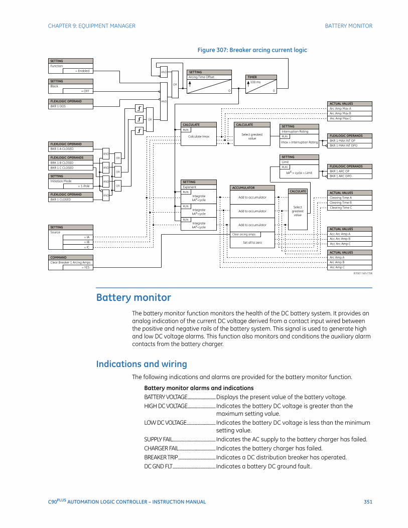
CHAPTER 9: EQUIPMENT MANAGER BATTERY MONITOR
C90PLUS AUTOMATION LOGIC CONTROLLER – INSTRUCTION MANUAL 351
Figure 307: Breaker arcing current logic
Battery monitorThe battery monitor function monitors the health of the DC battery system. It provides an analog indication of the current DC voltage derived from a contact input wired between the positive and negative rails of the battery system. This signal is used to generate high and low DC voltage alarms. This function also monitors and conditions the auxiliary alarm contacts from the battery charger.
Indications and wiringThe following indications and alarms are provided for the battery monitor function.
Battery monitor alarms and indicationsBATTERY VOLTAGE..............................Displays the present value of the battery voltage.HIGH DC VOLTAGE..............................Indicates the battery DC voltage is greater than the
maximum setting value.LOW DC VOLTAGE...............................Indicates the battery DC voltage is less than the minimum
setting value.SUPPLY FAIL..............................................Indicates the AC supply to the battery charger has failed.CHARGER FAIL.......................................Indicates the battery charger has failed.BREAKER TRIP........................................Indicates a DC distribution breaker has operated.DC GND FLT..............................................Indicates a battery DC ground fault.
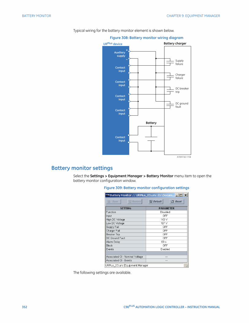
352 C90PLUS AUTOMATION LOGIC CONTROLLER – INSTRUCTION MANUAL
BATTERY MONITOR CHAPTER 9: EQUIPMENT MANAGER
Typical wiring for the battery monitor element is shown below.
Figure 308: Battery monitor wiring diagram
Battery monitor settingsSelect the Settings > Equipment Manager > Battery Monitor menu item to open the battery monitor configuration window.
Figure 309: Battery monitor configuration settings
The following settings are available.
CHAPTER 9: EQUIPMENT MANAGER BATTERY MONITOR
C90PLUS AUTOMATION LOGIC CONTROLLER – INSTRUCTION MANUAL 353
FunctionRange: Enabled, DisabledDefault: Disabled
This setting enables and disables the battery monitor element.
InputRange: any contact input or OFFDefault: OFF
This setting specifies the contact input used to monitor the battery voltage.
High DC VoltsRange: 38 to 275 volts in steps of 1Default: 143 volts
This setting is used to detect battery overcharging. This can result in loss of life, loss of electrolyte, and thermal runaway. This setting should be set above the expected voltage during an equalization charge.
Low DC VoltsRange: 38 to 275 volts in steps of 1Default: 107 volts
This setting is used to detect battery undercharging, which can lead to reduced cell capacity and sulfation. An undervoltage condition will also occur due to a charger failure.
Supply FailRange: any equipment manager operand or shared operandDefault: OFF
This setting selects the input connected to the AC supply failure contact.
Charger FailRange: any equipment manager operand or shared operandDefault: OFF
This setting selects the input connected to the charger critical failure contact.
Breaker TripRange: any equipment manager operand or shared operandDefault: OFF
This setting selects the input connected to the DC distribution breaker trip contact.
DC Ground FaultRange: any equipment manager operand or shared operandDefault: OFF
This setting specifies the input connected to the DC ground fault contact.
Alarm DelayRange: 2 to 300 seconds in steps of 1Default: 60 seconds
This setting specifies the time required for a field contact to be asserted before the corresponding alarm is declared.
BlockRange: any equipment manager operand or shared operandDefault: OFF
Assertion of the operand assigned to this setting blocks operation of the battery monitor element.
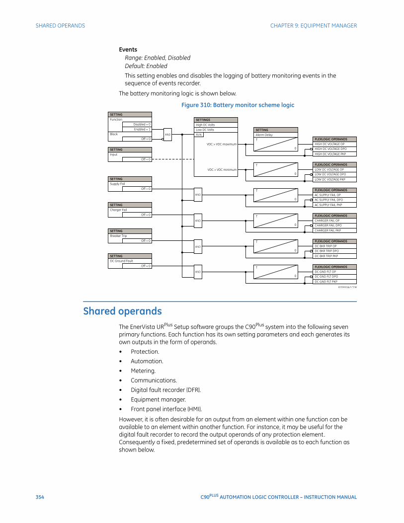
354 C90PLUS AUTOMATION LOGIC CONTROLLER – INSTRUCTION MANUAL
SHARED OPERANDS CHAPTER 9: EQUIPMENT MANAGER
EventsRange: Enabled, DisabledDefault: Enabled
This setting enables and disables the logging of battery monitoring events in the sequence of events recorder.
The battery monitoring logic is shown below.
Figure 310: Battery monitor scheme logic
Shared operandsThe EnerVista URPlus Setup software groups the C90Plus system into the following seven primary functions. Each function has its own setting parameters and each generates its own outputs in the form of operands.
• Protection.
• Automation.
• Metering.
• Communications.
• Digital fault recorder (DFR).
• Equipment manager.
• Front panel interface (HMI).
However, it is often desirable for an output from an element within one function can be available to an element within another function. For instance, it may be useful for the digital fault recorder to record the output operands of any protection element. Consequently a fixed, predetermined set of operands is available as to each function as shown below.
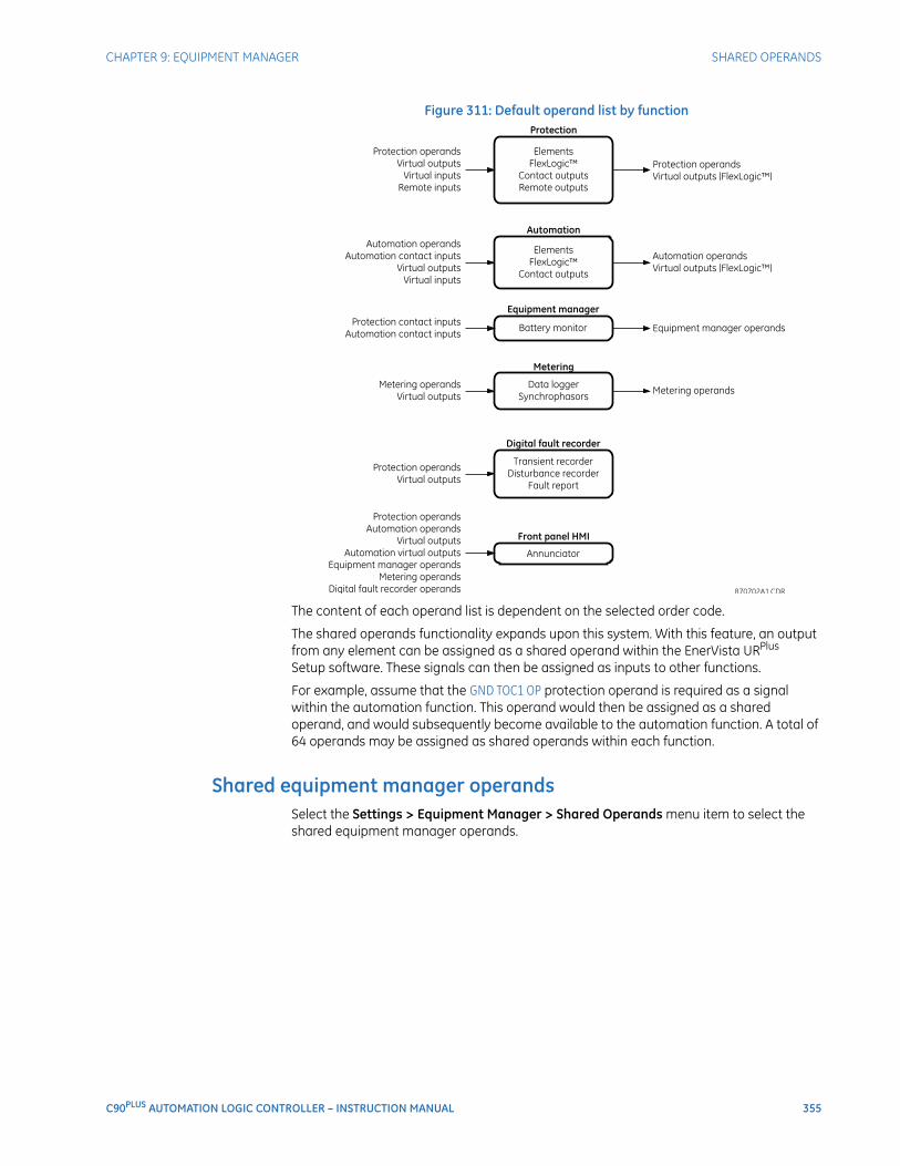
CHAPTER 9: EQUIPMENT MANAGER SHARED OPERANDS
C90PLUS AUTOMATION LOGIC CONTROLLER – INSTRUCTION MANUAL 355
Figure 311: Default operand list by function
The content of each operand list is dependent on the selected order code.
The shared operands functionality expands upon this system. With this feature, an output from any element can be assigned as a shared operand within the EnerVista URPlus Setup software. These signals can then be assigned as inputs to other functions.
For example, assume that the GND TOC1 OP protection operand is required as a signal within the automation function. This operand would then be assigned as a shared operand, and would subsequently become available to the automation function. A total of 64 operands may be assigned as shared operands within each function.
Shared equipment manager operandsSelect the Settings > Equipment Manager > Shared Operands menu item to select the shared equipment manager operands.
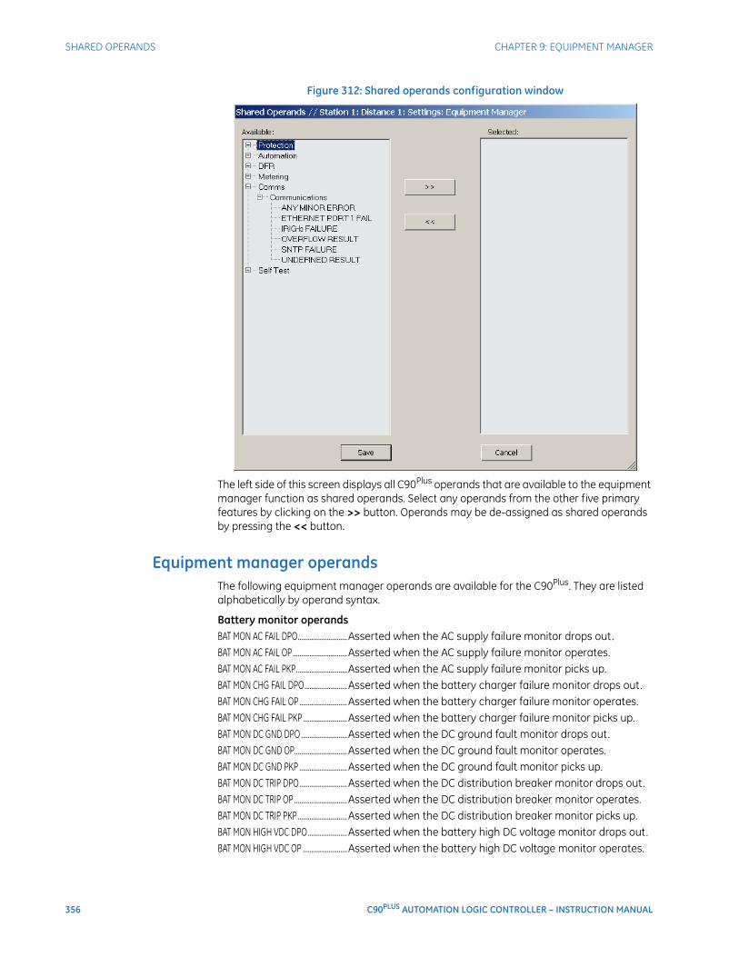
356 C90PLUS AUTOMATION LOGIC CONTROLLER – INSTRUCTION MANUAL
SHARED OPERANDS CHAPTER 9: EQUIPMENT MANAGER
Figure 312: Shared operands configuration window
The left side of this screen displays all C90Plus operands that are available to the equipment manager function as shared operands. Select any operands from the other five primary features by clicking on the >> button. Operands may be de-assigned as shared operands by pressing the << button.
Equipment manager operandsThe following equipment manager operands are available for the C90Plus. They are listed alphabetically by operand syntax.
Battery monitor operandsBAT MON AC FAIL DPO.............................Asserted when the AC supply failure monitor drops out.BAT MON AC FAIL OP................................Asserted when the AC supply failure monitor operates.BAT MON AC FAIL PKP..............................Asserted when the AC supply failure monitor picks up.BAT MON CHG FAIL DPO.........................Asserted when the battery charger failure monitor drops out.BAT MON CHG FAIL OP ............................Asserted when the battery charger failure monitor operates.BAT MON CHG FAIL PKP ..........................Asserted when the battery charger failure monitor picks up.BAT MON DC GND DPO ...........................Asserted when the DC ground fault monitor drops out.BAT MON DC GND OP...............................Asserted when the DC ground fault monitor operates.BAT MON DC GND PKP ............................Asserted when the DC ground fault monitor picks up.BAT MON DC TRIP DPO............................Asserted when the DC distribution breaker monitor drops out.BAT MON DC TRIP OP ...............................Asserted when the DC distribution breaker monitor operates.BAT MON DC TRIP PKP .............................Asserted when the DC distribution breaker monitor picks up.BAT MON HIGH VDC DPO.......................Asserted when the battery high DC voltage monitor drops out.BAT MON HIGH VDC OP ..........................Asserted when the battery high DC voltage monitor operates.

CHAPTER 9: EQUIPMENT MANAGER SHARED OPERANDS
C90PLUS AUTOMATION LOGIC CONTROLLER – INSTRUCTION MANUAL 357
BAT MON HIGH VDC PKP ........................Asserted when the battery high DC voltage monitor picks up.BAT MON LOW VDC DPO ........................Asserted when the battery low DC voltage monitor drops out.BAT MON LOW VDC OP............................Asserted when the battery low DC voltage monitor operates.BAT MON LOW VDC PKP .........................Asserted when the battery low DC voltage monitor picks up.
Breaker arcing current operandsBKR 1 ARC DPO...........................................Asserted when breaker arcing 1 element drops out.BKR 1 ARC OP ..............................................Asserted when breaker arcing 1 element operates.BKR 1 MAX INT DPO ..................................Asserted when the maximum symmetrical interruption of the
breaker arcing 1 element drops out.BKR 1 MAX INT OP .....................................Asserted when the maximum symmetrical interruption of the
breaker arcing 1 element operates.BKR 2... ............................................................The operands listed above are available for the breaker arcing
2 element.

358 C90PLUS AUTOMATION LOGIC CONTROLLER – INSTRUCTION MANUAL
SHARED OPERANDS CHAPTER 9: EQUIPMENT MANAGER
C90PLUS AUTOMATION LOGIC CONTROLLER – INSTRUCTION MANUAL 359
C90Plus Automation Logic Controller
Chapter 10: Digital fault recorder
Digital fault recorder
The digital fault recorder captures detailed information regarding abnormal occurrences in the power system. The information captured by the DFR is stored in the C90Plus in non-volatile memory and can be accessed through the front panel interface. The DFR consists of four primary functions.
• A sequence of events recorder that provides a time-stamped record of the operation of breakers, protection elements, and alarms. The recording of events is enabled on a per-element basis.
• A fault report that records fault type, magnitude and duration of the fault, and the response of protection functions.
• A transient recorder that records analog and digital signals for short duration events at a high resolution.
• A disturbance recorder that records analog and digital signals for long duration events, such as power swings and voltage sags, at a resolution of one sample per cycle.
Sequence of events recorderThis sequence of events recorder provides a time-stamped record of state changes of signals monitored by the C90Plus. These signals include the state of circuit breakers and disconnect switches, external alarms and indications, and any of the internal functions of the IED. The C90Plus can store a total of 8192 events. Once this memory is filled, the oldest events are overwritten. The events are time-stamped with an accuracy of 1 ms.
Most C90Plus elements contain an Events setting. When this setting is enabled, state changes for FlexLogic™ operands associated with the element are written to the sequence of events recorder. If this setting is disabled then state changes for the element are not recorded.
Front panel operationThe sequence of events record can be accessed from the front panel through the digital fault recorder (DFR) page. Using the navigations keys, the user can scroll or page through the events list. Two cursors are provided for measurement of the time difference between events.
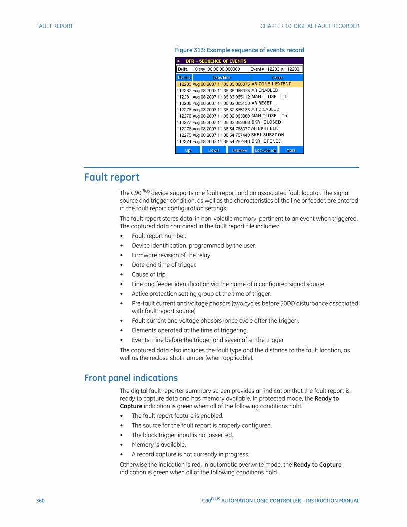
360 C90PLUS AUTOMATION LOGIC CONTROLLER – INSTRUCTION MANUAL
FAULT REPORT CHAPTER 10: DIGITAL FAULT RECORDER
Figure 313: Example sequence of events record
Fault reportThe C90Plus device supports one fault report and an associated fault locator. The signal source and trigger condition, as well as the characteristics of the line or feeder, are entered in the fault report configuration settings.
The fault report stores data, in non-volatile memory, pertinent to an event when triggered. The captured data contained in the fault report file includes:
• Fault report number.
• Device identification, programmed by the user.
• Firmware revision of the relay.
• Date and time of trigger.
• Cause of trip.
• Line and feeder identification via the name of a configured signal source.
• Active protection setting group at the time of trigger.
• Pre-fault current and voltage phasors (two cycles before 50DD disturbance associated with fault report source).
• Fault current and voltage phasors (once cycle after the trigger).
• Elements operated at the time of triggering.
• Events: nine before the trigger and seven after the trigger.
The captured data also includes the fault type and the distance to the fault location, as well as the reclose shot number (when applicable).
Front panel indicationsThe digital fault reporter summary screen provides an indication that the fault report is ready to capture data and has memory available. In protected mode, the Ready to Capture indication is green when all of the following conditions hold.
• The fault report feature is enabled.
• The source for the fault report is properly configured.
• The block trigger input is not asserted.
• Memory is available.
• A record capture is not currently in progress.
Otherwise the indication is red. In automatic overwrite mode, the Ready to Capture indication is green when all of the following conditions hold.
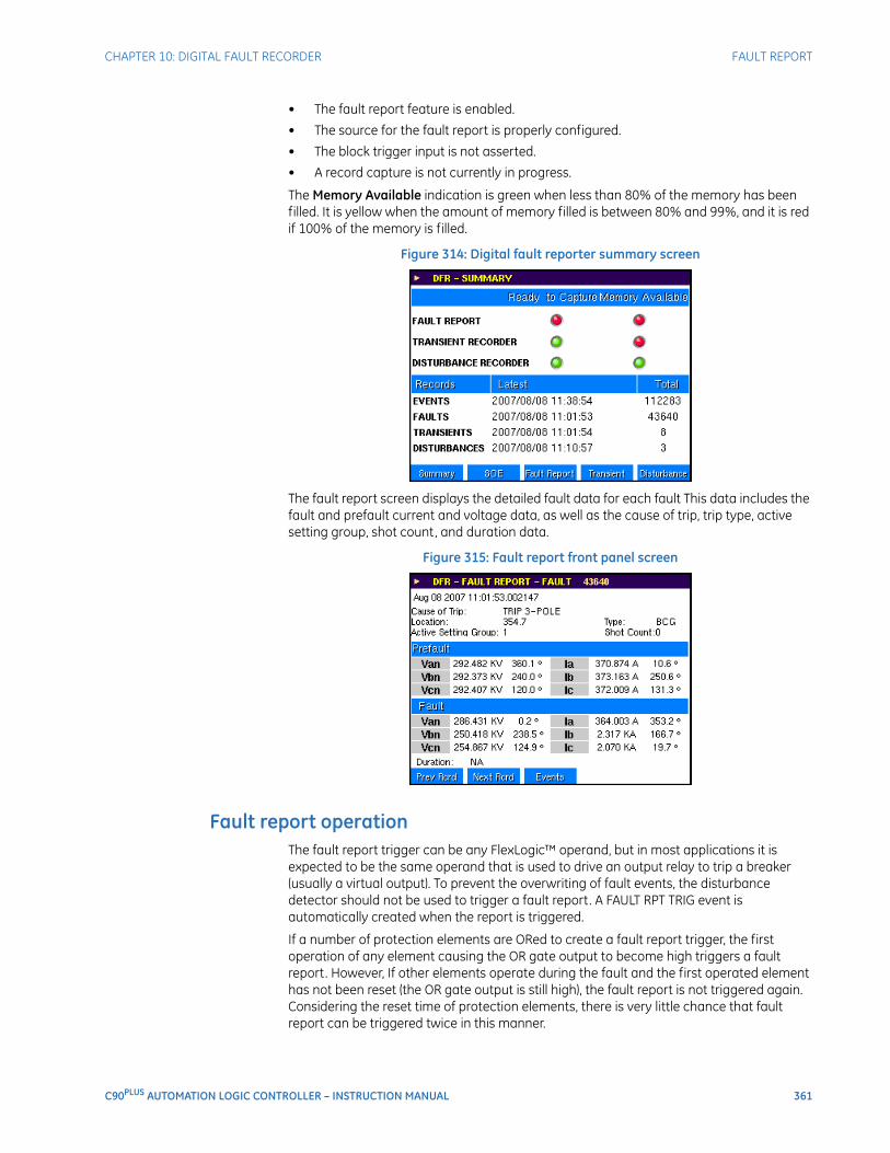
CHAPTER 10: DIGITAL FAULT RECORDER FAULT REPORT
C90PLUS AUTOMATION LOGIC CONTROLLER – INSTRUCTION MANUAL 361
• The fault report feature is enabled.
• The source for the fault report is properly configured.
• The block trigger input is not asserted.
• A record capture is not currently in progress.
The Memory Available indication is green when less than 80% of the memory has been filled. It is yellow when the amount of memory filled is between 80% and 99%, and it is red if 100% of the memory is filled.
Figure 314: Digital fault reporter summary screen
The fault report screen displays the detailed fault data for each fault This data includes the fault and prefault current and voltage data, as well as the cause of trip, trip type, active setting group, shot count, and duration data.
Figure 315: Fault report front panel screen
Fault report operationThe fault report trigger can be any FlexLogic™ operand, but in most applications it is expected to be the same operand that is used to drive an output relay to trip a breaker (usually a virtual output). To prevent the overwriting of fault events, the disturbance detector should not be used to trigger a fault report. A FAULT RPT TRIG event is automatically created when the report is triggered.
If a number of protection elements are ORed to create a fault report trigger, the first operation of any element causing the OR gate output to become high triggers a fault report. However, If other elements operate during the fault and the first operated element has not been reset (the OR gate output is still high), the fault report is not triggered again. Considering the reset time of protection elements, there is very little chance that fault report can be triggered twice in this manner.
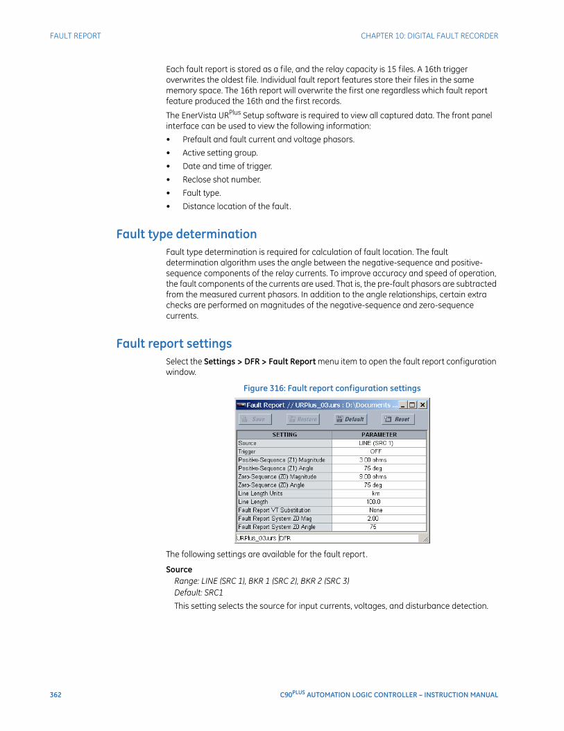
362 C90PLUS AUTOMATION LOGIC CONTROLLER – INSTRUCTION MANUAL
FAULT REPORT CHAPTER 10: DIGITAL FAULT RECORDER
Each fault report is stored as a file, and the relay capacity is 15 files. A 16th trigger overwrites the oldest file. Individual fault report features store their files in the same memory space. The 16th report will overwrite the first one regardless which fault report feature produced the 16th and the first records.
The EnerVista URPlus Setup software is required to view all captured data. The front panel interface can be used to view the following information:
• Prefault and fault current and voltage phasors.
• Active setting group.
• Date and time of trigger.
• Reclose shot number.
• Fault type.
• Distance location of the fault.
Fault type determinationFault type determination is required for calculation of fault location. The fault determination algorithm uses the angle between the negative-sequence and positive-sequence components of the relay currents. To improve accuracy and speed of operation, the fault components of the currents are used. That is, the pre-fault phasors are subtracted from the measured current phasors. In addition to the angle relationships, certain extra checks are performed on magnitudes of the negative-sequence and zero-sequence currents.
Fault report settingsSelect the Settings > DFR > Fault Report menu item to open the fault report configuration window.
Figure 316: Fault report configuration settings
The following settings are available for the fault report.
SourceRange: LINE (SRC 1), BKR 1 (SRC 2), BKR 2 (SRC 3)Default: SRC1
This setting selects the source for input currents, voltages, and disturbance detection.

CHAPTER 10: DIGITAL FAULT RECORDER FAULT REPORT
C90PLUS AUTOMATION LOGIC CONTROLLER – INSTRUCTION MANUAL 363
TriggerRange: any FlexLogic™ operandDefault: OFF
This setting assigns the FlexLogic™ operand representing the protection elements requiring operational fault location calculations. The distance to fault calculations are initiated by this signal.
Positive-Sequence (Z1) MagnitudeRange: 0.01 to 250.00 ohms in steps of 0.01Default: 3.00 ohms
This setting specifies the magnitude of positive-sequence impedance of the transmission line or feeder in secondary ohms.
Positive-Sequence (Z1) AngleRange: 25 to 90° in steps of 1Default: 75°
This setting specifies the angle of positive-sequence impedance of the transmission line or feeder in secondary ohms.
Zero-Sequence (Z0) MagnitudeRange: 0.01 to 650.00 ohms in steps of 0.01Default: 9.00 ohms
This setting specifies the magnitude of zero-sequence impedance of the transmission line or feeder in secondary ohms.
Zero-Sequence (Z0) AngleRange: 25 to 90° in steps of 1Default: 75°
This setting specifies the angle of zero-sequence impedance of the transmission line or feeder in secondary ohms.
Line Length UnitsRange: km, milesDefault: km
This setting selects the units used for fault location calculations.
Line LengthRange: 0.0 to 2000.0 in steps of 0.1Default: 100.0
This setting specifies the length of the transmission line or feeder in the defined line length units.
Fault Report VT SubstitutionRange: None, I0, V0Default: None
Program this setting to “None” if the C90Plus is fed from wye-connected VTs. If delta-connected VTs are used, and the C90Plus is supplied with the neutral (3V0) voltage, set to “V0”. The method is still exact, as the fault locator would combine the line-to-line voltage measurements with the neutral voltage measurement to re-create the line-to-ground voltages. It required to configure the delta and neutral voltages under the source indicated as input for the fault report. Also, the C90Plus will check if the auxiliary signal configured is marked as “Vn” by the user (under VT setup), and inhibit the fault location if the auxiliary signal is labeled differently.
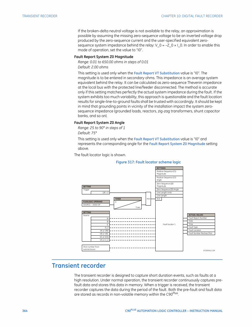
364 C90PLUS AUTOMATION LOGIC CONTROLLER – INSTRUCTION MANUAL
TRANSIENT RECORDER CHAPTER 10: DIGITAL FAULT RECORDER
If the broken-delta neutral voltage is not available to the relay, an approximation is possible by assuming the missing zero-sequence voltage to be an inverted voltage drop produced by the zero-sequence current and the user-specified equivalent zero-sequence system impedance behind the relay: V_0 = –Z_0 × I_0. In order to enable this mode of operation, set the value to “I0”.
Fault Report System Z0 MagnitudeRange: 0.01 to 650.00 ohms in steps of 0.01Default: 2.00 ohms
This setting is used only when the Fault Report VT Substitution value is “I0”. The magnitude is to be entered in secondary ohms. This impedance is an average system equivalent behind the relay. It can be calculated as zero-sequence Thevenin impedance at the local bus with the protected line/feeder disconnected. The method is accurate only if this setting matches perfectly the actual system impedance during the fault. If the system exhibits too much variability, this approach is questionable and the fault location results for single-line-to-ground faults shall be trusted with accordingly. It should be kept in mind that grounding points in vicinity of the installation impact the system zero-sequence impedance (grounded loads, reactors, zig-zag transformers, shunt capacitor banks, and so on).
Fault Report System Z0 AngleRange: 25 to 90° in steps of 1Default: 75°
This setting is used only when the Fault Report VT Substitution value is “I0” and represents the corresponding angle for the Fault Report System Z0 Magnitude setting above.
The fault locator logic is shown.
Figure 317: Fault locator scheme logic
Transient recorderThe transient recorder is designed to capture short duration events, such as faults at a high resolution. Under normal operation, the transient recorder continuously captures pre-fault data and stores this data in memory. When a trigger is received, the transient recorder captures the data during the period of the fault . Both the pre-fault and fault data are stored as records in non-volatile memory within the C90Plus.
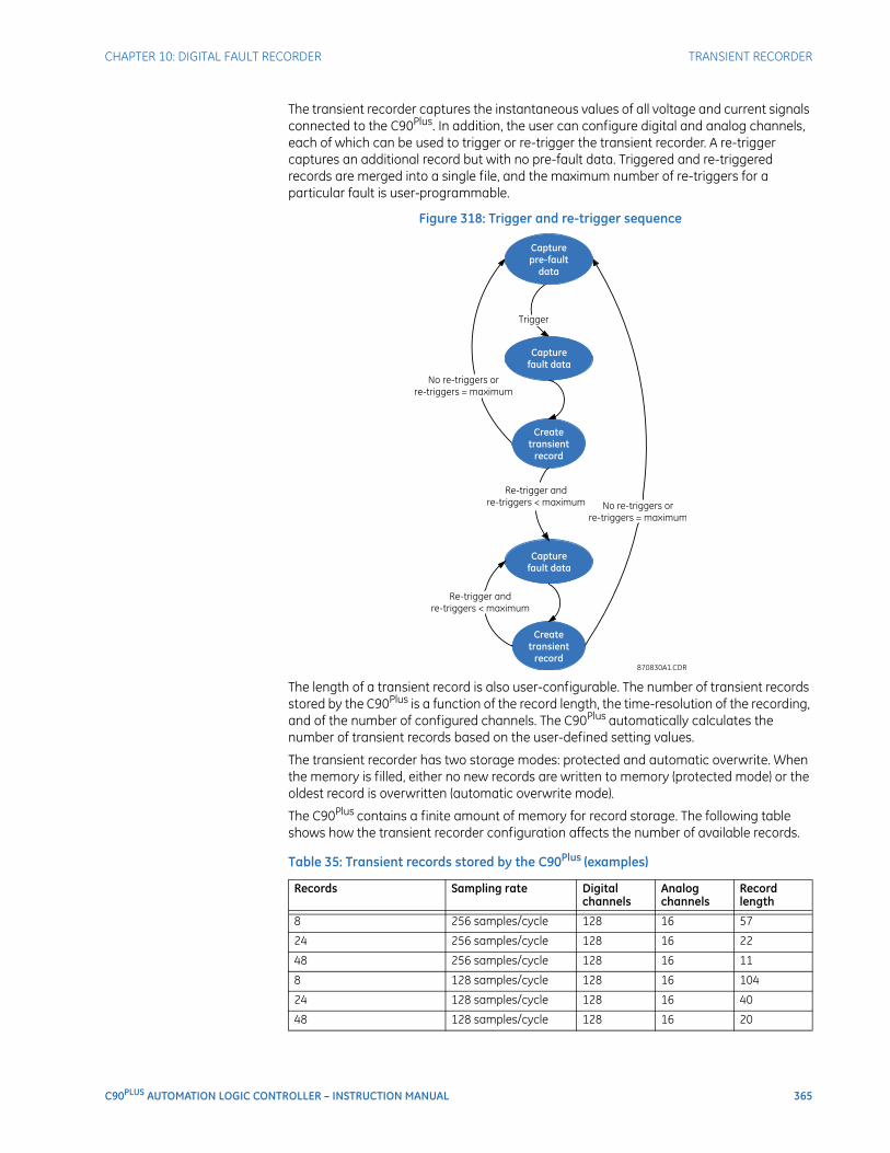
CHAPTER 10: DIGITAL FAULT RECORDER TRANSIENT RECORDER
C90PLUS AUTOMATION LOGIC CONTROLLER – INSTRUCTION MANUAL 365
The transient recorder captures the instantaneous values of all voltage and current signals connected to the C90Plus. In addition, the user can configure digital and analog channels, each of which can be used to trigger or re-trigger the transient recorder. A re-trigger captures an additional record but with no pre-fault data. Triggered and re-triggered records are merged into a single file, and the maximum number of re-triggers for a particular fault is user-programmable.
Figure 318: Trigger and re-trigger sequence
The length of a transient record is also user-configurable. The number of transient records stored by the C90Plus is a function of the record length, the time-resolution of the recording, and of the number of configured channels. The C90Plus automatically calculates the number of transient records based on the user-defined setting values.
The transient recorder has two storage modes: protected and automatic overwrite. When the memory is filled, either no new records are written to memory (protected mode) or the oldest record is overwritten (automatic overwrite mode).
The C90Plus contains a finite amount of memory for record storage. The following table shows how the transient recorder configuration affects the number of available records.
Table 35: Transient records stored by the C90Plus (examples)
Records Sampling rate Digital channels
Analog channels
Record length
8 256 samples/cycle 128 16 57
24 256 samples/cycle 128 16 22
48 256 samples/cycle 128 16 11
8 128 samples/cycle 128 16 104
24 128 samples/cycle 128 16 40
48 128 samples/cycle 128 16 20
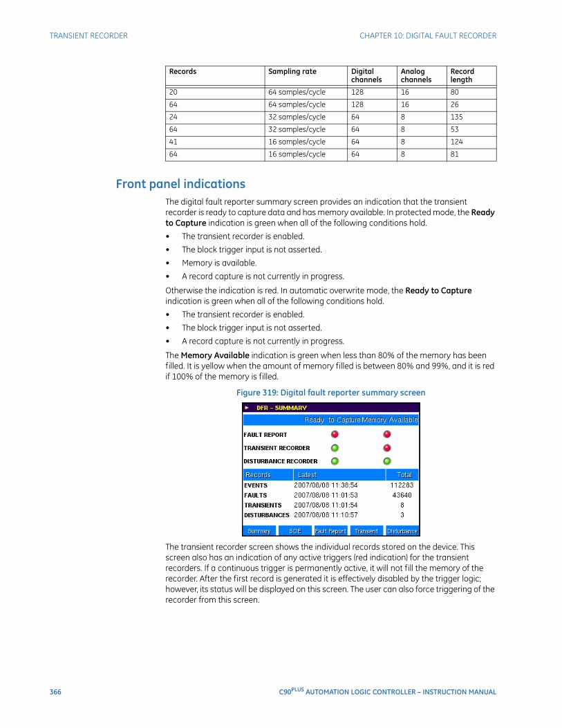
366 C90PLUS AUTOMATION LOGIC CONTROLLER – INSTRUCTION MANUAL
TRANSIENT RECORDER CHAPTER 10: DIGITAL FAULT RECORDER
Front panel indicationsThe digital fault reporter summary screen provides an indication that the transient recorder is ready to capture data and has memory available. In protected mode, the Ready to Capture indication is green when all of the following conditions hold.
• The transient recorder is enabled.
• The block trigger input is not asserted.
• Memory is available.
• A record capture is not currently in progress.
Otherwise the indication is red. In automatic overwrite mode, the Ready to Capture indication is green when all of the following conditions hold.
• The transient recorder is enabled.
• The block trigger input is not asserted.
• A record capture is not currently in progress.
The Memory Available indication is green when less than 80% of the memory has been filled. It is yellow when the amount of memory filled is between 80% and 99%, and it is red if 100% of the memory is filled.
Figure 319: Digital fault reporter summary screen
The transient recorder screen shows the individual records stored on the device. This screen also has an indication of any active triggers (red indication) for the transient recorders. If a continuous trigger is permanently active, it will not fill the memory of the recorder. After the first record is generated it is effectively disabled by the trigger logic; however, its status will be displayed on this screen. The user can also force triggering of the recorder from this screen.
20 64 samples/cycle 128 16 80
64 64 samples/cycle 128 16 26
24 32 samples/cycle 64 8 135
64 32 samples/cycle 64 8 53
41 16 samples/cycle 64 8 124
64 16 samples/cycle 64 8 81
Records Sampling rate Digital channels
Analog channels
Record length
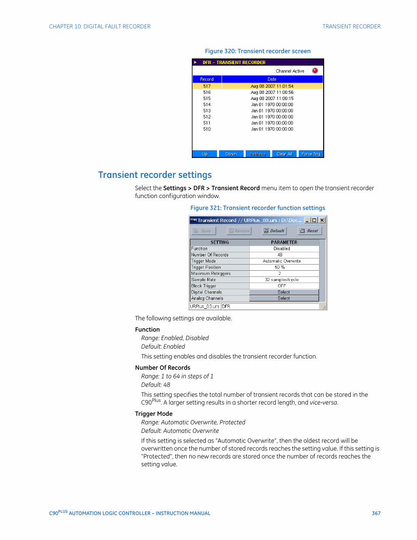
CHAPTER 10: DIGITAL FAULT RECORDER TRANSIENT RECORDER
C90PLUS AUTOMATION LOGIC CONTROLLER – INSTRUCTION MANUAL 367
Figure 320: Transient recorder screen
Transient recorder settingsSelect the Settings > DFR > Transient Record menu item to open the transient recorder function configuration window.
Figure 321: Transient recorder function settings
The following settings are available.
FunctionRange: Enabled, DisabledDefault: Enabled
This setting enables and disables the transient recorder function.
Number Of RecordsRange: 1 to 64 in steps of 1Default: 48
This setting specifies the total number of transient records that can be stored in the C90Plus. A larger setting results in a shorter record length, and vice-versa.
Trigger ModeRange: Automatic Overwrite, ProtectedDefault: Automatic Overwrite
If this setting is selected as “Automatic Overwrite”, then the oldest record will be overwritten once the number of stored records reaches the setting value. If this setting is “Protected”, then no new records are stored once the number of records reaches the setting value.

368 C90PLUS AUTOMATION LOGIC CONTROLLER – INSTRUCTION MANUAL
TRANSIENT RECORDER CHAPTER 10: DIGITAL FAULT RECORDER
Trigger PositionRange: 1 to 100% in steps of 1Default: 50%
This setting specifies the amount of pre-trigger data stored in a record expressed as a percentage of record length.
Maximum Re-TriggersRange: 1 to 4 in steps of 1Default: 2
This setting selects the maximum number of re-trigger records that can be generated for an event. The value is limited to one less than the number of records that can be stored (up to a maximum of four records).
Sample RateRange: 16, 32, 64, 128, or 256 samples per cycle, or OFFDefault: 32
This setting selects the time-resolution of the transient record. A larger setting necessarily results in a shorter record length.
Block TriggerRange: any FlexLogic™ operand or shared operandDefault: OFF
When the operand assigned to this setting is asserted, all triggers to the transient recorder are inhibited.
NOTE
NOTE: When changes are made to the transient recorder settings, all existing transient records will be cleared!
NOTE
NOTE: The transient recorder will start collecting data upon power up or after the recorder is cleared. If a trigger occurs immediately after a power up or the clearing of transient records, and there is not enough pre-trigger data, then the pre-trigger will be set to the amount of data collected and will not reflect the value specified by the user.
.
The transient recorder trigger logic is shown below.
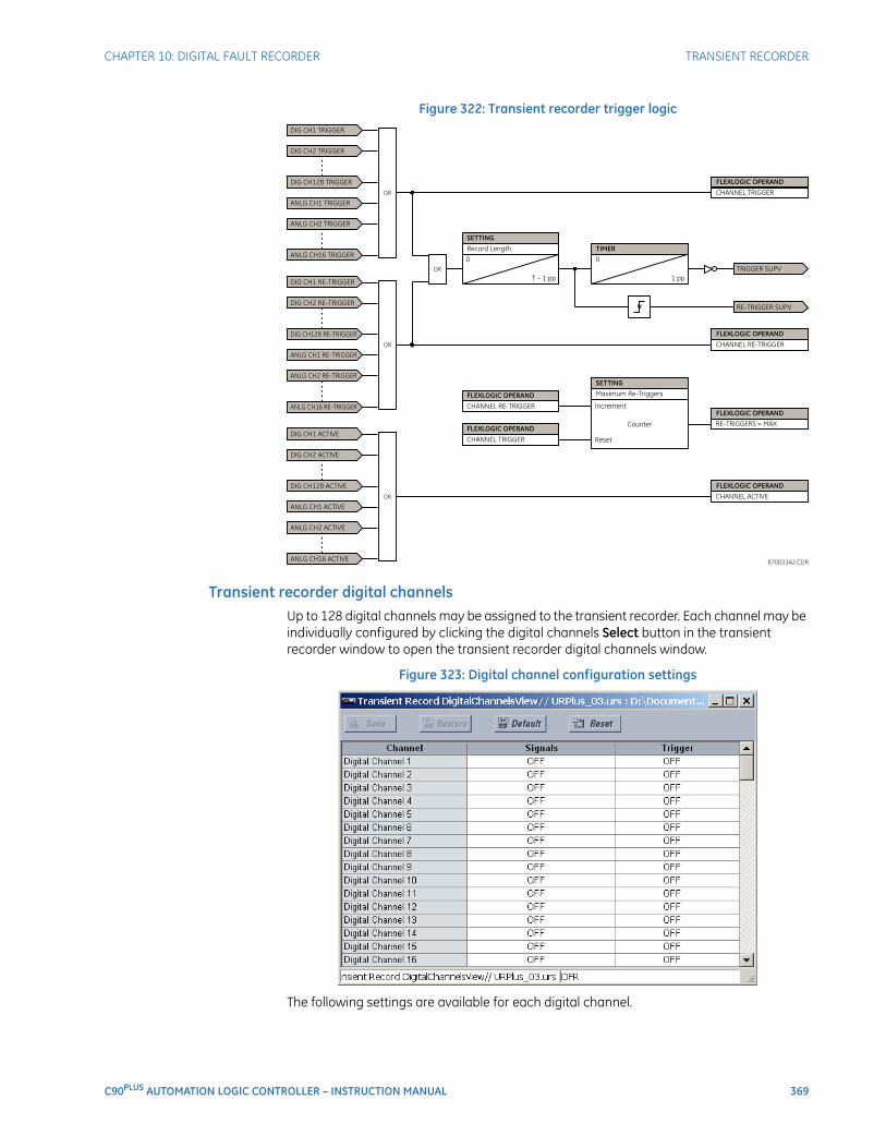
CHAPTER 10: DIGITAL FAULT RECORDER TRANSIENT RECORDER
C90PLUS AUTOMATION LOGIC CONTROLLER – INSTRUCTION MANUAL 369
Figure 322: Transient recorder trigger logic
Transient recorder digital channelsUp to 128 digital channels may be assigned to the transient recorder. Each channel may be individually configured by clicking the digital channels Select button in the transient recorder window to open the transient recorder digital channels window.
Figure 323: Digital channel configuration settings
The following settings are available for each digital channel.
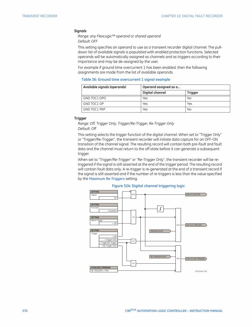
370 C90PLUS AUTOMATION LOGIC CONTROLLER – INSTRUCTION MANUAL
TRANSIENT RECORDER CHAPTER 10: DIGITAL FAULT RECORDER
SignalsRange: any FlexLogic™ operand or shared operandDefault: OFF
This setting specifies an operand to use as a transient recorder digital channel. The pull-down list of available signals is populated with enabled protection functions. Selected operands will be automatically assigned as channels and as triggers according to their importance and may be de-assigned by the user.
For example if ground time overcurrent 1 has been enabled, then the following assignments are made from the list of available operands.
Table 36: Ground time overcurrent 1 signal example
TriggerRange: Off, Trigger Only, Trigger/Re-Trigger, Re-Trigger OnlyDefault: Off
This setting selects the trigger function of the digital channel. When set to “Trigger Only” or “Trigger/Re-Trigger”, the transient recorder will initiate data capture for an OFF-ON transition of the channel signal. The resulting record will contain both pre-fault and fault data and the channel must return to the off state before it can generate a subsequent trigger.
When set to “Trigger/Re-Trigger” or “Re-Trigger Only”, the transient recorder will be re-triggered if the signal is still asserted at the end of the trigger period. The resulting record will contain fault data only. A re-trigger is re-generated at the end of a transient record if the signal is still asserted and if the number of re-triggers is less than the value specified by the Maximum Re-Triggers setting.
Figure 324: Digital channel triggering logic
Available signals (operands) Operand assigned as a...
Digital channel Trigger
GND TOC1 DPO Yes No
GND TOC1 OP Yes Yes
GND TOC1 PKP Yes No
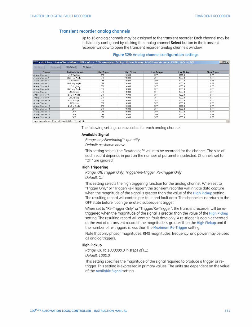
CHAPTER 10: DIGITAL FAULT RECORDER TRANSIENT RECORDER
C90PLUS AUTOMATION LOGIC CONTROLLER – INSTRUCTION MANUAL 371
Transient recorder analog channelsUp to 16 analog channels may be assigned to the transient recorder. Each channel may be individually configured by clicking the analog channel Select button in the transient recorder window to open the transient recorder analog channels window.
Figure 325: Analog channel configuration settings
The following settings are available for each analog channel.
Available SignalRange: any FlexAnalog™ quantityDefault: as shown above
This setting selects the FlexAnalog™ value to be recorded for the channel. The size of each record depends in part on the number of parameters selected. Channels set to “Off” are ignored.
High TriggeringRange: Off, Trigger Only, Trigger/Re-Trigger, Re-Trigger OnlyDefault: Off
This setting selects the high triggering function for the analog channel. When set to “Trigger Only” or “Trigger/Re-Trigger”, the transient recorder will initiate data capture when the magnitude of the signal is greater than the value of the High Pickup setting. The resulting record will contain pre-fault and fault data. The channel must return to the OFF state before it can generate a subsequent trigger.
When set to “Re-Trigger Only” or “Trigger/Re-Trigger”, the transient recorder will be re-triggered when the magnitude of the signal is greater than the value of the High Pickup setting. The resulting record will contain fault data only. A re-trigger is again generated at the end of a transient record if the magnitude is greater than the High Pickup and if the number of re-triggers is less than the Maximum Re-Trigger setting.
Note that only phasor magnitudes, RMS magnitudes, frequency, and power may be used as analog triggers.
High PickupRange: 0.0 to 1000000.0 in steps of 0.1Default: 1000.0
This setting specifies the magnitude of the signal required to produce a trigger or re-trigger. This setting is expressed in primary values. The units are dependent on the value of the Available Signal setting.

372 C90PLUS AUTOMATION LOGIC CONTROLLER – INSTRUCTION MANUAL
TRANSIENT RECORDER CHAPTER 10: DIGITAL FAULT RECORDER
Low TriggeringRange: Enabled, DisabledDefault: Disabled
This setting selects the low triggering function for the analog channel. When set to “Trigger Only” or “Trigger/Re-Trigger”, the transient recorder will initiate data capture when the magnitude of the signal is less than the value of the Low Pickup setting. The resulting record will contain both pre-fault and fault data. The channel must return to the off state before it can generate a subsequent trigger.
When set to “Trigger/Re-Trigger” or “Trigger Only”, the transient recorder will be re-triggered when the magnitude of the signal is less than the value of the Low Pickup setting. The resulting transient record will contain fault data only. A re-trigger is generated again at the end of the record if the magnitude is less than the Low Pickup and if the number of re-triggers is less than the Maximum Re-Trigger setting.
Note that only phasor magnitudes, RMS magnitudes, frequency, and power may be used as analog triggers.
Low PickupRange: 0.0 to 1000000.0 in steps of 0.1Default: 1000.0
This setting specifies the magnitude of the signal required to produce a trigger or re-trigger. This setting is expressed in primary values. The units are dependent on the value of the Available Signal setting.
Block TriggerRange: any FlexLogic™ operand or shared operandDefault: OFF
When the operand assigned to this setting is asserted, all high and low triggers to the specified analog channel are inhibited.
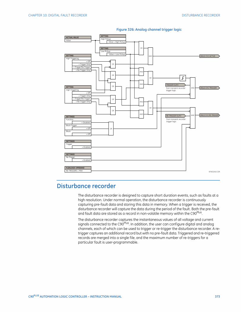
CHAPTER 10: DIGITAL FAULT RECORDER DISTURBANCE RECORDER
C90PLUS AUTOMATION LOGIC CONTROLLER – INSTRUCTION MANUAL 373
Figure 326: Analog channel trigger logic
Disturbance recorderThe disturbance recorder is designed to capture short duration events, such as faults at a high resolution. Under normal operation, the disturbance recorder is continuously capturing pre-fault data and storing this data in memory. When a trigger is received, the disturbance recorder will capture the data during the period of the fault. Both the pre-fault and fault data are stored as a record in non-volatile memory within the C90Plus.
The disturbance recorder captures the instantaneous values of all voltage and current signals connected to the C90Plus. In addition, the user can configure digital and analog channels, each of which can be used to trigger or re-trigger the disturbance recorder. A re-trigger captures an additional record but with no pre-fault data. Triggered and re-triggered records are merged into a single file, and the maximum number of re-triggers for a particular fault is user-programmable.
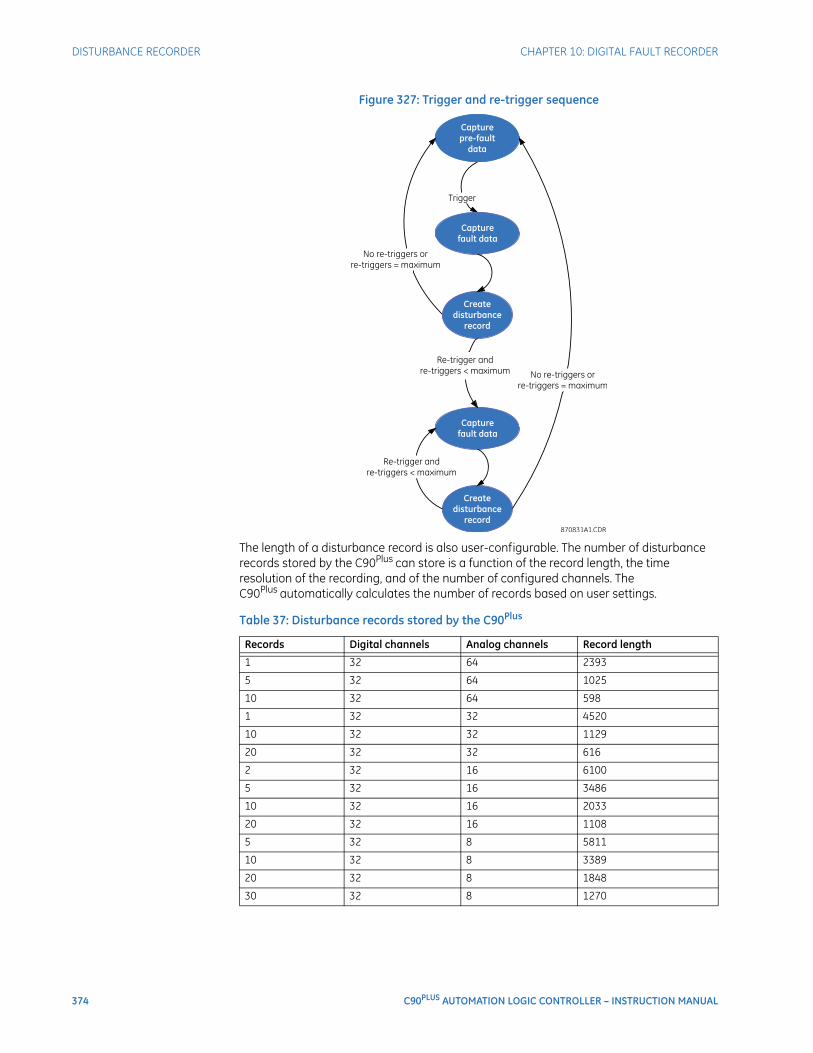
374 C90PLUS AUTOMATION LOGIC CONTROLLER – INSTRUCTION MANUAL
DISTURBANCE RECORDER CHAPTER 10: DIGITAL FAULT RECORDER
Figure 327: Trigger and re-trigger sequence
The length of a disturbance record is also user-configurable. The number of disturbance records stored by the C90Plus can store is a function of the record length, the time resolution of the recording, and of the number of configured channels. The C90Plus automatically calculates the number of records based on user settings.
Table 37: Disturbance records stored by the C90Plus
Records Digital channels Analog channels Record length
1 32 64 2393
5 32 64 1025
10 32 64 598
1 32 32 4520
10 32 32 1129
20 32 32 616
2 32 16 6100
5 32 16 3486
10 32 16 2033
20 32 16 1108
5 32 8 5811
10 32 8 3389
20 32 8 1848
30 32 8 1270
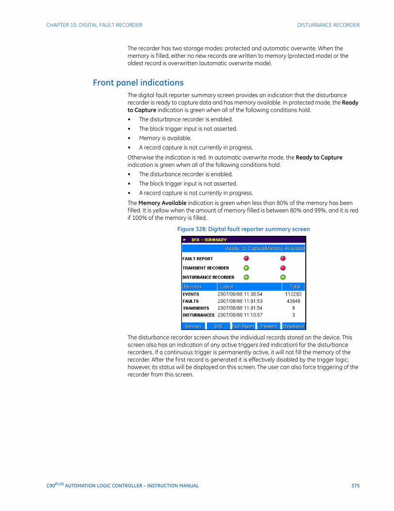
CHAPTER 10: DIGITAL FAULT RECORDER DISTURBANCE RECORDER
C90PLUS AUTOMATION LOGIC CONTROLLER – INSTRUCTION MANUAL 375
The recorder has two storage modes: protected and automatic overwrite. When the memory is filled, either no new records are written to memory (protected mode) or the oldest record is overwritten (automatic overwrite mode).
Front panel indicationsThe digital fault reporter summary screen provides an indication that the disturbance recorder is ready to capture data and has memory available. In protected mode, the Ready to Capture indication is green when all of the following conditions hold.
• The disturbance recorder is enabled.
• The block trigger input is not asserted.
• Memory is available.
• A record capture is not currently in progress.
Otherwise the indication is red. In automatic overwrite mode, the Ready to Capture indication is green when all of the following conditions hold.
• The disturbance recorder is enabled.
• The block trigger input is not asserted.
• A record capture is not currently in progress.
The Memory Available indication is green when less than 80% of the memory has been filled. It is yellow when the amount of memory filled is between 80% and 99%, and it is red if 100% of the memory is filled.
Figure 328: Digital fault reporter summary screen
The disturbance recorder screen shows the individual records stored on the device. This screen also has an indication of any active triggers (red indication) for the disturbance recorders. If a continuous trigger is permanently active, it will not fill the memory of the recorder. After the first record is generated it is effectively disabled by the trigger logic; however, its status will be displayed on this screen. The user can also force triggering of the recorder from this screen.
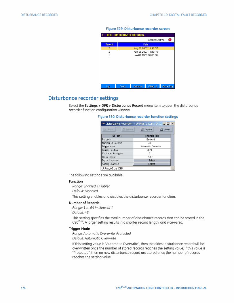
376 C90PLUS AUTOMATION LOGIC CONTROLLER – INSTRUCTION MANUAL
DISTURBANCE RECORDER CHAPTER 10: DIGITAL FAULT RECORDER
Figure 329: Disturbance recorder screen
Disturbance recorder settingsSelect the Settings > DFR > Disturbance Record menu item to open the disturbance recorder function configuration window.
Figure 330: Disturbance recorder function settings
The following settings are available.
FunctionRange: Enabled, DisabledDefault: Disabled
This setting enables and disables the disturbance recorder function.
Number of RecordsRange: 1 to 64 in steps of 1Default: 48
This setting specifies the total number of disturbance records that can be stored in the C90Plus. A larger setting results in a shorter record length, and vice-versa.
Trigger ModeRange: Automatic Overwrite, ProtectedDefault: Automatic Overwrite
If this setting value is “Automatic Overwrite”, then the oldest disturbance record will be overwritten once the number of stored records reaches the setting value. If this value is “Protected”, then no new disturbance record are stored once the number of records reaches the setting value.
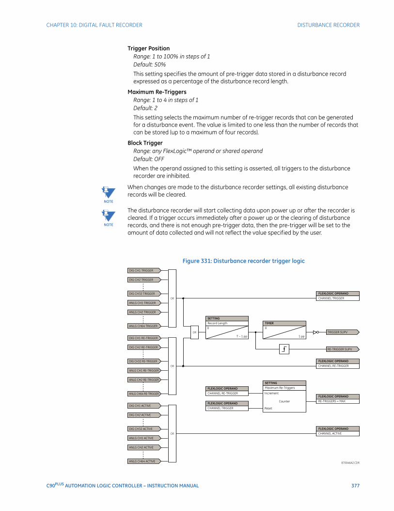
CHAPTER 10: DIGITAL FAULT RECORDER DISTURBANCE RECORDER
C90PLUS AUTOMATION LOGIC CONTROLLER – INSTRUCTION MANUAL 377
Trigger PositionRange: 1 to 100% in steps of 1Default: 50%
This setting specifies the amount of pre-trigger data stored in a disturbance record expressed as a percentage of the disturbance record length.
Maximum Re-TriggersRange: 1 to 4 in steps of 1Default: 2
This setting selects the maximum number of re-trigger records that can be generated for a disturbance event. The value is limited to one less than the number of records that can be stored (up to a maximum of four records).
Block TriggerRange: any FlexLogic™ operand or shared operandDefault: OFF
When the operand assigned to this setting is asserted, all triggers to the disturbance recorder are inhibited.
NOTE
NOTE: When changes are made to the disturbance recorder settings, all existing disturbance records will be cleared.
NOTE
NOTE: The disturbance recorder will start collecting data upon power up or after the recorder is cleared. If a trigger occurs immediately after a power up or the clearing of disturbance records, and there is not enough pre-trigger data, then the pre-trigger will be set to the amount of data collected and will not reflect the value specified by the user.
.
Figure 331: Disturbance recorder trigger logic
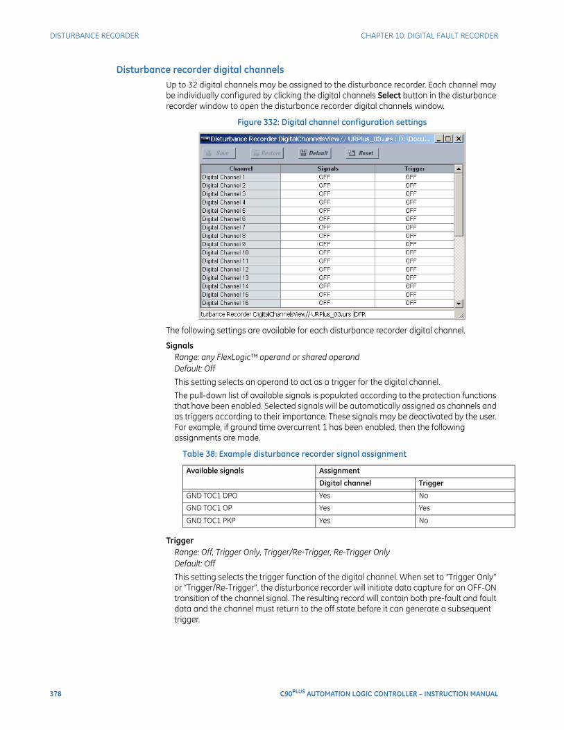
378 C90PLUS AUTOMATION LOGIC CONTROLLER – INSTRUCTION MANUAL
DISTURBANCE RECORDER CHAPTER 10: DIGITAL FAULT RECORDER
Disturbance recorder digital channelsUp to 32 digital channels may be assigned to the disturbance recorder. Each channel may be individually configured by clicking the digital channels Select button in the disturbance recorder window to open the disturbance recorder digital channels window.
Figure 332: Digital channel configuration settings
The following settings are available for each disturbance recorder digital channel.
SignalsRange: any FlexLogic™ operand or shared operandDefault: Off
This setting selects an operand to act as a trigger for the digital channel.
The pull-down list of available signals is populated according to the protection functions that have been enabled. Selected signals will be automatically assigned as channels and as triggers according to their importance. These signals may be deactivated by the user. For example, if ground time overcurrent 1 has been enabled, then the following assignments are made.
Table 38: Example disturbance recorder signal assignment
TriggerRange: Off, Trigger Only, Trigger/Re-Trigger, Re-Trigger OnlyDefault: Off
This setting selects the trigger function of the digital channel. When set to “Trigger Only” or “Trigger/Re-Trigger”, the disturbance recorder will initiate data capture for an OFF-ON transition of the channel signal. The resulting record will contain both pre-fault and fault data and the channel must return to the off state before it can generate a subsequent trigger.
Available signals Assignment
Digital channel Trigger
GND TOC1 DPO Yes No
GND TOC1 OP Yes Yes
GND TOC1 PKP Yes No
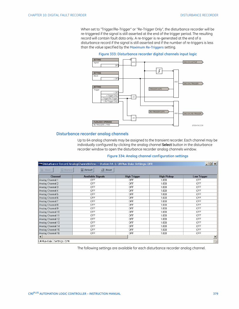
CHAPTER 10: DIGITAL FAULT RECORDER DISTURBANCE RECORDER
C90PLUS AUTOMATION LOGIC CONTROLLER – INSTRUCTION MANUAL 379
When set to “Trigger/Re-Trigger” or “Re-Trigger Only”, the disturbance recorder will be re-triggered if the signal is still asserted at the end of the trigger period. The resulting record will contain fault data only. A re-trigger is re-generated at the end of a disturbance record if the signal is still asserted and if the number of re-triggers is less than the value specified by the Maximum Re-Triggers setting.
Figure 333: Disturbance recorder digital channels input logic
Disturbance recorder analog channelsUp to 64 analog channels may be assigned to the transient recorder. Each channel may be individually configured by clicking the analog channel Select button in the disturbance recorder window to open the disturbance recorder analog channels window.
Figure 334: Analog channel configuration settings
The following settings are available for each disturbance recorder analog channel.

380 C90PLUS AUTOMATION LOGIC CONTROLLER – INSTRUCTION MANUAL
DISTURBANCE RECORDER CHAPTER 10: DIGITAL FAULT RECORDER
SignalRange: any FlexAnalog™ quantityDefault: Off
This setting specifies the FlexAnalog™ quantity to be recorded for the channel. The size of each disturbance record depends in part on the number of parameters selected. Parameters set to “Off” are ignored.
High TriggeringRange: Off, Trigger Only, Trigger/Re-Trigger, Re-Trigger OnlyDefault: Off
This setting selects the high triggering function for the analog channel. When set to “Trigger Only” or “Trigger/Re-Trigger”, the disturbance recorder will initiate data capture when the magnitude of the signal is greater than the value of the High Pickup setting. The resulting record will contain pre-fault and fault data. The channel must return to the OFF state before it can generate a subsequent trigger.
When set to “Re-Trigger Only” or “Trigger/Re-Trigger”, the disturbance recorder will be re-triggered when the magnitude of the signal is greater than the value of the High Pickup setting. The resulting record will contain fault data only. A re-trigger is again generated at the end of a disturbance record if the magnitude is greater than the High Pickup and if the number of re-triggers is less than the Maximum Re-Trigger setting.
Note that only phasor magnitudes, RMS magnitudes, frequency, and power may be used as analog triggers.
High PickupRange: 0.0 to 1000000.0Default: 1000.0
This setting specifies the magnitude of the signal required to produce a trigger or re-trigger. This setting is expressed in primary values. The units are dependent on the value of the Available Signal setting.
Low TriggeringRange: Off, Trigger Only, Trigger/Re-Trigger, Re-Trigger OnlyDefault: Off
This setting selects the low triggering function for the analog channel. When set to “Trigger Only” or “Trigger/Re-Trigger”, the disturbance recorder will initiate data capture when the magnitude of the signal is less than the value of the Low Pickup setting. The resulting record will contain both pre-fault and fault data. The channel must return to the off state before it can generate a subsequent trigger.
When set to “Trigger/Re-Trigger” or “Trigger Only”, the disturbance recorder will be re-triggered when the magnitude of the signal is less than the value of the Low Pickup setting. The resulting disturbance record will contain fault data only. A re-trigger is generated again at the end of the record if the magnitude is less than the Low Pickup and if the number of re-triggers is less than the Maximum Re-Trigger setting.
Note that only phasor magnitudes, RMS magnitudes, frequency, and power may be used as analog triggers.
Low PickupRange: 0.0 to 1000000.0Default: 1000.0
This setting specifies the magnitude of the signal required to produce a trigger or re-trigger. This setting is expressed in primary values. The units are dependent on the value of the Available Signal setting.
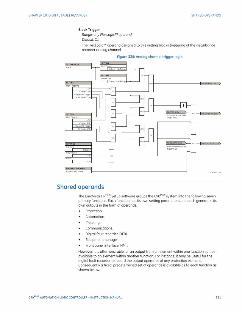
CHAPTER 10: DIGITAL FAULT RECORDER SHARED OPERANDS
C90PLUS AUTOMATION LOGIC CONTROLLER – INSTRUCTION MANUAL 381
Block TriggerRange: any FlexLogic™ operandDefault: Off
The FlexLogic™ operand assigned to this setting blocks triggering of the disturbance recorder analog channel.
Figure 335: Analog channel trigger logic
Shared operandsThe EnerVista URPlus Setup software groups the C90Plus system into the following seven primary functions. Each function has its own setting parameters and each generates its own outputs in the form of operands.
• Protection.
• Automation.
• Metering.
• Communications.
• Digital fault recorder (DFR).
• Equipment manager.
• Front panel interface (HMI).
However, it is often desirable for an output from an element within one function can be available to an element within another function. For instance, it may be useful for the digital fault recorder to record the output operands of any protection element. Consequently a fixed, predetermined set of operands is available as to each function as shown below.
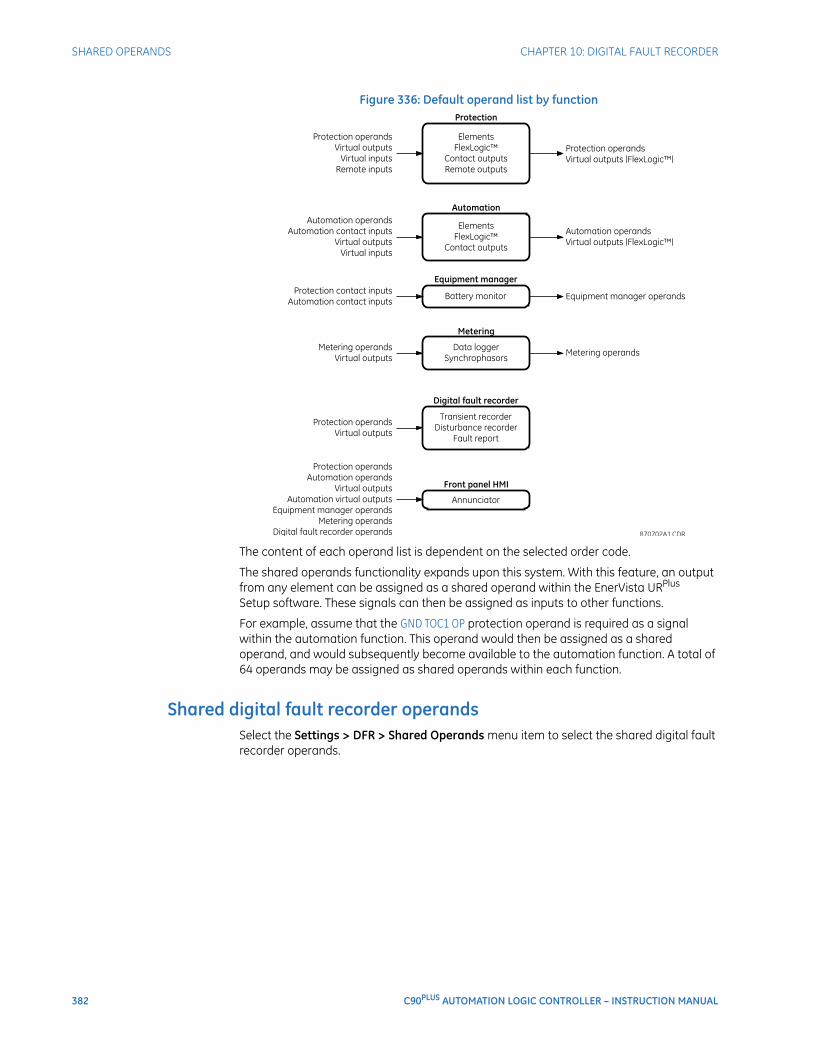
382 C90PLUS AUTOMATION LOGIC CONTROLLER – INSTRUCTION MANUAL
SHARED OPERANDS CHAPTER 10: DIGITAL FAULT RECORDER
Figure 336: Default operand list by function
The content of each operand list is dependent on the selected order code.
The shared operands functionality expands upon this system. With this feature, an output from any element can be assigned as a shared operand within the EnerVista URPlus Setup software. These signals can then be assigned as inputs to other functions.
For example, assume that the GND TOC1 OP protection operand is required as a signal within the automation function. This operand would then be assigned as a shared operand, and would subsequently become available to the automation function. A total of 64 operands may be assigned as shared operands within each function.
Shared digital fault recorder operandsSelect the Settings > DFR > Shared Operands menu item to select the shared digital fault recorder operands.
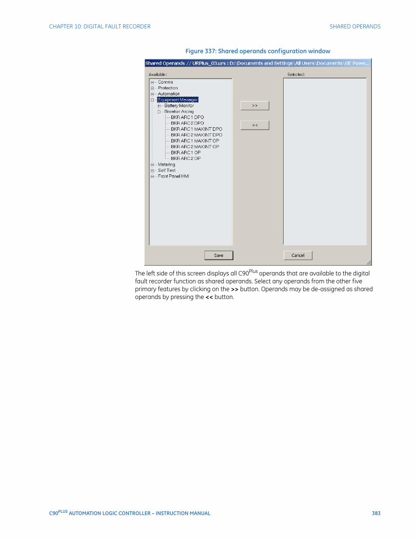
CHAPTER 10: DIGITAL FAULT RECORDER SHARED OPERANDS
C90PLUS AUTOMATION LOGIC CONTROLLER – INSTRUCTION MANUAL 383
Figure 337: Shared operands configuration window
The left side of this screen displays all C90Plus operands that are available to the digital fault recorder function as shared operands. Select any operands from the other five primary features by clicking on the >> button. Operands may be de-assigned as shared operands by pressing the << button.

384 C90PLUS AUTOMATION LOGIC CONTROLLER – INSTRUCTION MANUAL
SHARED OPERANDS CHAPTER 10: DIGITAL FAULT RECORDER
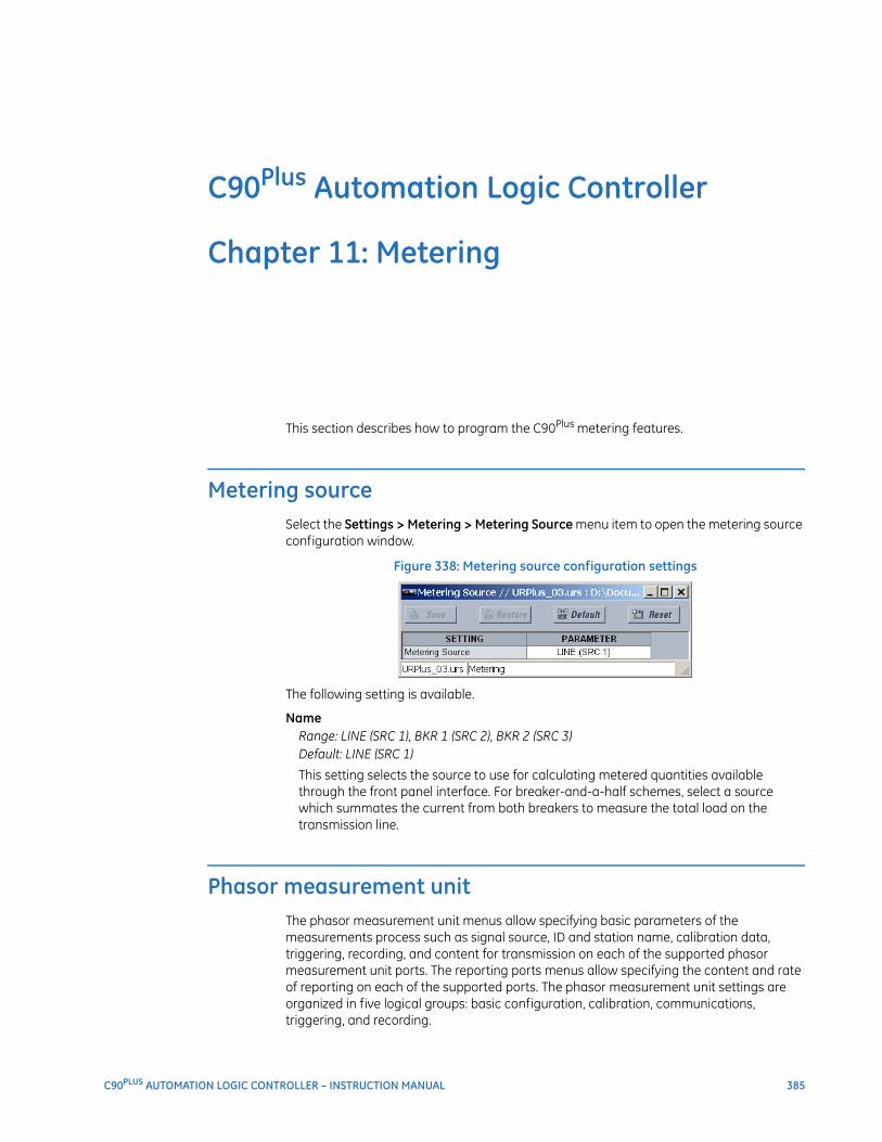
C90PLUS AUTOMATION LOGIC CONTROLLER – INSTRUCTION MANUAL 385
C90Plus Automation Logic Controller
Chapter 11: Metering
Metering
This section describes how to program the C90Plus metering features.
Metering sourceSelect the Settings > Metering > Metering Source menu item to open the metering source configuration window.
Figure 338: Metering source configuration settings
The following setting is available.
NameRange: LINE (SRC 1), BKR 1 (SRC 2), BKR 2 (SRC 3)Default: LINE (SRC 1)
This setting selects the source to use for calculating metered quantities available through the front panel interface. For breaker-and-a-half schemes, select a source which summates the current from both breakers to measure the total load on the transmission line.
Phasor measurement unitThe phasor measurement unit menus allow specifying basic parameters of the measurements process such as signal source, ID and station name, calibration data, triggering, recording, and content for transmission on each of the supported phasor measurement unit ports. The reporting ports menus allow specifying the content and rate of reporting on each of the supported ports. The phasor measurement unit settings are organized in five logical groups: basic configuration, calibration, communications, triggering, and recording.
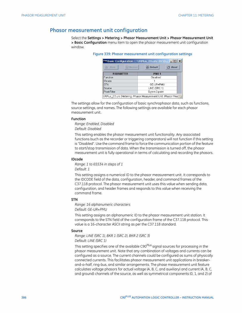
386 C90PLUS AUTOMATION LOGIC CONTROLLER – INSTRUCTION MANUAL
PHASOR MEASUREMENT UNIT CHAPTER 11: METERING
Phasor measurement unit configurationSelect the Settings > Metering > Phasor Measurement Unit > Phasor Measurement Unit > Basic Configuration menu item to open the phasor measurement unit configuration window.
Figure 339: Phasor measurement unit configuration settings
The settings allow for the configuration of basic synchrophasor data, such as functions, source settings, and names. The following settings are available for each phasor measurement unit.
FunctionRange: Enabled, DisabledDefault: Disabled
This setting enables the phasor measurement unit functionality. Any associated functions (such as the recorder or triggering comparators) will not function if this setting is “Disabled”. Use the command frame to force the communication portion of the feature to start/stop transmission of data. When the transmission is turned off, the phasor measurement unit is fully operational in terms of calculating and recording the phasors.
IDcodeRange: 1 to 65534 in steps of 1Default: 1
This setting assigns a numerical ID to the phasor measurement unit. It corresponds to the IDCODE field of the data, configuration, header, and command frames of the C37.118 protocol. The phasor measurement unit uses this value when sending data, configuration, and header frames and responds to this value when receiving the command frame.
STNRange: 16 alphanumeric charactersDefault: GE-UR+PMU
This setting assigns an alphanumeric ID to the phasor measurement unit station. It corresponds to the STN field of the configuration frame of the C37.118 protocol. This value is a 16-character ASCII string as per the C37.118 standard.
SourceRange: LINE (SRC 1), BKR 1 (SRC 2), BKR 2 (SRC 3)Default: LINE (SRC 1)
This setting specifies one of the available C90Plus signal sources for processing in the phasor measurement unit. Note that any combination of voltages and currents can be configured as a source. The current channels could be configured as sums of physically connected currents. This facilitates phasor measurement unit applications in breaker-and-a-half, ring-bus, and similar arrangements. The phase measurement unit feature calculates voltage phasors for actual voltage (A, B, C, and auxiliary) and current (A, B, C, and ground) channels of the source, as well as symmetrical components (0, 1, and 2) of

CHAPTER 11: METERING PHASOR MEASUREMENT UNIT
C90PLUS AUTOMATION LOGIC CONTROLLER – INSTRUCTION MANUAL 387
both voltages and currents. When configuring communication and recording features of the phasor measurement unit, the user could select – from the above superset – the content to be sent out or recorded.
Post-FilterRange: None, Symm-3-point, Symm-5-point, Symm-7-pointDefault: Symm-3-point
This setting specifies amount of post-filtering applied to raw synchrophasor measurements. The raw measurements are produced at the rate of nominal system frequency using one-cycle data windows. This setting is provided to deal with interfering frequencies and to balance speed and accuracy of synchrophasor measurements for different applications. The following filtering choices are available.
– None: No post-filtering.
– Symm-3-point: Symmetrical three-point filter (one historical point, one present point, one future point).
– Symm-5-point: Symmetrical five-point filter (two historical points, one present point, two future points).
– Symm-7-point: Symmetrical seven-point filter (three historical points, one present point, three future points).
This setting applies to all channels of the phasor measurement unit. It is effectively for recording and transmission on all ports configured to use data for the phasor measurement unit.
Phasor measurement unit calibrationSelect the Settings > Metering > Synchrophasors > PMU Calibration menu item to open the phasor measurement unit calibration window.
Figure 340: Phasor measurement unit calibration settings
The following settings are available for each phasor measurement unit. These settings specify user angle calibration data. This data is combined with the factory adjustments to shift the phasors for better accuracy.
Va Angle, Vb Angle, Vc Angle, Vx AngleRange: –5.00 to 5.00° in steps of 0.05Default: 0.00°
These settings recognize applications with protection class voltage and current sources, and allow the user to calibrate each channel (phase A, B, and C voltage, as well as auxiliary voltage) individually to offset errors introduced by VTs, CTs, and cabling. The

388 C90PLUS AUTOMATION LOGIC CONTROLLER – INSTRUCTION MANUAL
PHASOR MEASUREMENT UNIT CHAPTER 11: METERING
setting values are effectively added to the measured angles. Therefore, enter a positive correction of the secondary signal lags the true signal; and negative value if the secondary signal leads the true signal.
Ia Angle, Ib Angle, Ic Angle, Ig AngleRange: –5.00 to 5.00° in steps of 0.05Default: 0.00°
These settings recognize applications with protection class voltage and current sources, and allow the user to calibrate each channel (ground current and phase A, B, and C currents) individually to offset errors introduced by VTs, CTs, and cabling. The setting values are effectively added to the measured angles. Therefore, enter a positive correction of the secondary signal lags the true signal; and negative value if the secondary signal leads the true signal.
Sequence Voltage Shift AngleRange: –180 to 180° in steps of 30Default: 0°
This setting allows correcting positive and negative-sequence voltages for vector groups of power transformers located between the phasor measurement unit voltage point and the reference node. This angle is effectively added to the positive-sequence voltage angle, and subtracted from the negative-sequence voltage angle. Please note the following.
– When this setting value is not “0°”, the phase and sequence voltages will not agree. Unlike sequence voltages, the phase voltages cannot be corrected in a general case, and therefore are reported as measured.
– When receiving synchrophasor date at multiple locations, with possibly different reference nodes, it may be more beneficial to allow the central locations to perform the compensation of sequence voltages.
– This setting applies to phasor measurement unit data only. The C90Plus calculates symmetrical voltages independently for protection and control purposes without applying this correction.
– When connected to line-to-line voltages, the phasor measurement unit calculates symmetrical voltages with the reference to the AG voltage, and not to the physically connected AB voltage.
Sequence Current Shift AngleRange: –180 to 180° in steps of 30Default: 0°
This setting allows correcting positive and negative-sequence currents for vector groups of power transformers located between the phasor measurement unit current point and the reference node. The setting has the same meaning for currents as the Sequence Voltage Shift Angle setting has for voltages. Normally, the two correcting angles are set identically, except rare applications when the voltage and current measuring points are located at different windings of a power transformer.
Phasor measurement unit communicationsSelect the Settings > Metering > Phasor Measurement Unit > Communication > Comm Port menu item to open the phasor measurement unit communications window for port 1.
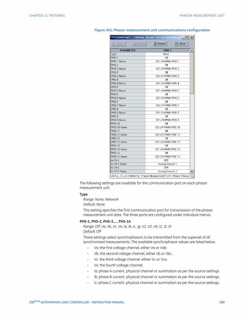
CHAPTER 11: METERING PHASOR MEASUREMENT UNIT
C90PLUS AUTOMATION LOGIC CONTROLLER – INSTRUCTION MANUAL 389
Figure 341: Phasor measurement unit communications configuration
The following settings are available for the communication port on each phasor measurement unit.
TypeRange: None, NetworkDefault: None
This setting specifies the first communication port for transmission of the phasor measurement unit data. The three ports are configured under individual menus.
PHS-1, PHS-2, PHS-3,..., PHS-14Range: Off, Va, Vb, Vc, Vx, Ia, Ib, Ic, Ig, V1, V2, V0, I1, I2, I0Default: Off
These settings select synchrophasors to be transmitted from the superset of all synchronized measurements. The available synchrophasor values are listed below.
– Va: the first voltage channel, either Va or Vab.
– Vb: the second voltage channel, either Vb or Vbc.
– Vc: the third voltage channel, either Vc or Vca.
– Vx: the fourth voltage channel.
– Ia: phase A current, physical channel or summation as per the source settings.
– Ib: phase B current, physical channel or summation as per the source settings.
– Ic: phase C current, physical channel or summation as per the source settings.
390 C90PLUS AUTOMATION LOGIC CONTROLLER – INSTRUCTION MANUAL
PHASOR MEASUREMENT UNIT CHAPTER 11: METERING
– Ig: fourth current channel, physical or summation as per the source settings.
– V1: positive-sequence voltage, referenced to Va.
– V2: negative-sequence voltage, referenced to Va.
– V0: zero-sequence voltage.
– I1: positive-sequence current, referenced to Ia.
– I2: negative-sequence current, referenced to Ia.
– I0: zero-sequence current.
These settings allow for optimizing the frame size and maximizing transmission channel usage, depending on a given application. Select “Off” to suppress transmission of a given value.
PHS-1 Name, PHS-2 Name, PHS-3 Name,..., PHS-14 NameRange: 16 alphanumeric charactersDefault: GE-UR+PMU1-V1, GE-UR+PMU1-V2, GE-UR-PMU1+V3,..., GE-UR+PMU1-V14
These settings allow for custom naming of the synchrophasor channels. Sixteen-character ASCII strings are allowed as in the CHNAM field of the configuration frame. These names are typically based on station, bus, or breaker names.
A-CH-1, A-CH-2, A-CH-3,..., A-CH-14Range: available FlexAnalog™ valuesDefault: Off
These settings select any analog data measured by the relay to be included as a user-selectable analog channel of the data frame. Up to eight analog channels can be configured to send any FlexAnalog™ value from the relay. Examples include active and reactive power, per phase or three-phase power, power factor, temperature via RTD inputs, and THD. The configured analog values are sampled concurrently with the synchrophasor instant and sent as 16-bit integer values.
A-CH-1 Name, A-CH-2 Name, A-CH-3 Name,..., A-CH-14 NameRange: 16 alphanumeric charactersDefault: AnalogChannel1, AnalogChannel2, AnalogChannel3,..., AnalogChannel14
These settings allow for custom naming of the analog channels. Sixteen-character ASCII strings are allowed as in the CHNAM field of the configuration frame.
D-CH-1, D-CH-2, D-CH-3,..., D-CH-14Range: any metering logic operand or shared operandDefault: Off
These settings select any digital flag measured by the relay to be included as a user-selectable digital channel of the data frame. Up to sixteen analog channels can be configured to send any operand from the relay. The configured digital flags are sampled concurrently with the synchrophasor instant. The values are mapped into a two-byte integer number, with byte 1 LSB corresponding to the digital channel 1 and byte 2 MSB corresponding to digital channel 16.
D-CH-1 Name, D-CH-2 Name, D-CH-3 Name,..., D-CH-14 NameRange: 16 alphanumeric charactersDefault: DigitalChannel1, DigitalChannel2, DigitalChannel3,..., DigitalChannel14
These settings allow for custom naming of the digital channels. Sixteen-character ASCII strings are allowed as in the CHNAM field of the configuration frame.

CHAPTER 11: METERING PHASOR MEASUREMENT UNIT
C90PLUS AUTOMATION LOGIC CONTROLLER – INSTRUCTION MANUAL 391
D-CH-1 Normal State, D-CH-2 Normal State, D-CH-3 Normal State,..., D-CH-14 Normal State
Range: On, OffDefault: Off
These settings allow for specifying a normal state for each digital channel. These states are transmitted in configuration frames to the data concentrator.
Phasor measurement unit triggeringEach logical phasor measurement unit (PMU) contains five triggering mechanisms to facilitate triggering of the associated PMU recorder and cross-triggering of other PMUs of the system. They are:
• Overfrequency and underfrequency.
• Overvoltage and undervoltage.
• Overcurrent.
• Overpower.
• High rate of change of frequency.
The pre-configured triggers can be augmented with a user-programmable trigger. This trigger can be built freely using programmable logic of the relay. The entire triggering logic is refreshed once every two power system cycles.
Select the Settings > Metering > Phasor Measurement Unit > Triggering > User Triggering menu item to open the phasor measurement unit user-programmable trigger window.
Figure 342: User-programmable trigger configuration setting
The following user-programmable trigger setting is available.
FunctionRange: any metering operand or shared operandDefault: OFF
This setting selects an operand to use as a user-specified trigger.
All five triggering functions and the user-programmable trigger are consolidated (ORed) and connected to the PMU recorder. Each trigger can be programmed to log its operation into the event recorder. The five triggers drive the STAT bits of the data frame to inform the destination of the synchrophasor data regarding the cause of trigger. The following convention is adopted to drive bits 11, 3, 2, 1, and 0 of the STAT word.
Figure 343: STAT bits logic
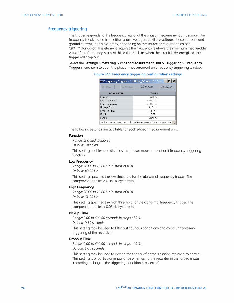
392 C90PLUS AUTOMATION LOGIC CONTROLLER – INSTRUCTION MANUAL
PHASOR MEASUREMENT UNIT CHAPTER 11: METERING
Frequency triggeringThe trigger responds to the frequency signal of the phasor measurement unit source. The frequency is calculated from either phase voltages, auxiliary voltage, phase currents and ground current, in this hierarchy, depending on the source configuration as per C90Plus standards. This element requires the frequency is above the minimum measurable value. If the frequency is below this value, such as when the circuit is de-energized, the trigger will drop out.
Select the Settings > Metering > Phasor Measurement Unit > Triggering > Frequency Trigger menu item to open the phasor measurement unit frequency triggering window.
Figure 344: Frequency triggering configuration settings
The following settings are available for each phasor measurement unit.
FunctionRange: Enabled, DisabledDefault: Disabled
This setting enables and disables the phasor measurement unit frequency triggering function.
Low FrequencyRange: 20.00 to 70.00 Hz in steps of 0.01Default: 49.00 Hz
This setting specifies the low threshold for the abnormal frequency trigger. The comparator applies a 0.03 Hz hysteresis.
High FrequencyRange: 20.00 to 70.00 Hz in steps of 0.01Default: 61.00 Hz
This setting specifies the high threshold for the abnormal frequency trigger. The comparator applies a 0.03 Hz hysteresis.
Pickup TimeRange: 0.00 to 600.00 seconds in steps of 0.01Default: 0.10 seconds
This setting may be used to filter out spurious conditions and avoid unnecessary triggering of the recorder.
Dropout TimeRange: 0.00 to 600.00 seconds in steps of 0.01Default: 1.00 seconds
This setting may be used to extend the trigger after the situation returned to normal. This setting is of particular importance when using the recorder in the forced mode (recording as long as the triggering condition is asserted).
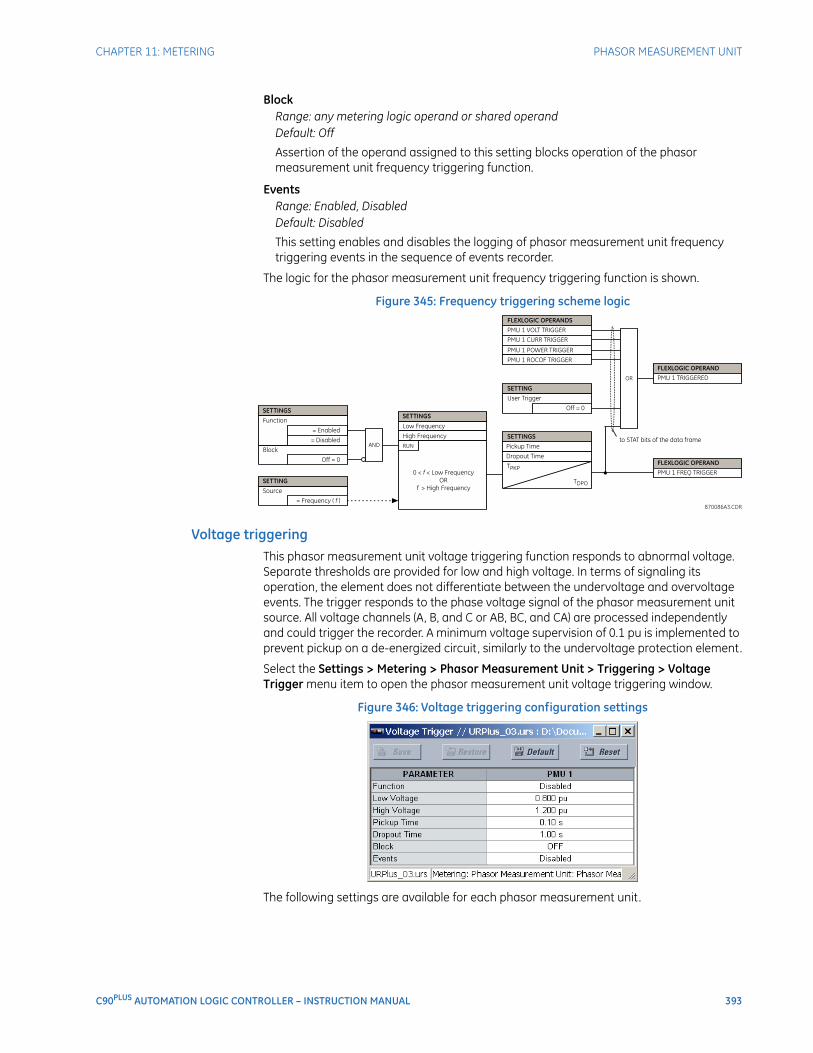
CHAPTER 11: METERING PHASOR MEASUREMENT UNIT
C90PLUS AUTOMATION LOGIC CONTROLLER – INSTRUCTION MANUAL 393
BlockRange: any metering logic operand or shared operandDefault: Off
Assertion of the operand assigned to this setting blocks operation of the phasor measurement unit frequency triggering function.
EventsRange: Enabled, DisabledDefault: Disabled
This setting enables and disables the logging of phasor measurement unit frequency triggering events in the sequence of events recorder.
The logic for the phasor measurement unit frequency triggering function is shown.
Figure 345: Frequency triggering scheme logic
Voltage triggeringThis phasor measurement unit voltage triggering function responds to abnormal voltage. Separate thresholds are provided for low and high voltage. In terms of signaling its operation, the element does not differentiate between the undervoltage and overvoltage events. The trigger responds to the phase voltage signal of the phasor measurement unit source. All voltage channels (A, B, and C or AB, BC, and CA) are processed independently and could trigger the recorder. A minimum voltage supervision of 0.1 pu is implemented to prevent pickup on a de-energized circuit, similarly to the undervoltage protection element.
Select the Settings > Metering > Phasor Measurement Unit > Triggering > Voltage Trigger menu item to open the phasor measurement unit voltage triggering window.
Figure 346: Voltage triggering configuration settings
The following settings are available for each phasor measurement unit.

394 C90PLUS AUTOMATION LOGIC CONTROLLER – INSTRUCTION MANUAL
PHASOR MEASUREMENT UNIT CHAPTER 11: METERING
FunctionRange: Enabled, DisabledDefault: Disabled
This setting enables and disables the phasor measurement unit voltage triggering function.
Low VoltageRange: 0.250 to 1.250 pu in steps of 0.001Default: 0.800 pu
This setting specifies the low threshold for the abnormal voltage trigger, in per-unit values of the phasor measurement unit source. A value of 1 pu is a nominal voltage value defined as the nominal secondary voltage times VT ratio. The comparator applies a 3% hysteresis.
High VoltageRange: 0.750 to 1.750 pu in steps of 0.001Default: 1.200 pu
This setting specifies the high threshold for the abnormal voltage trigger, in per-unit values of the phasor measurement unit source. A value of 1 pu is a nominal voltage value defined as the nominal secondary voltage times VT ratio. The comparator applies a 3% hysteresis.
Pickup TimeRange: 0.00 to 600.00 seconds in steps of 0.01Default: 0.10 seconds
This setting may be used to filter out spurious conditions and avoid unnecessary triggering of the recorder.
Dropout TimeRange: 0.00 to 600.00 seconds in steps of 0.01Default: 1.00 seconds
This setting may be used to extend the trigger after the situation returned to normal. This setting is of particular importance when using the recorder in the forced mode (recording as long as the triggering condition is asserted).
BlockRange: any metering logic operand or shared operandDefault: OFF
Assertion of the operand assigned to this setting blocks operation of the phasor measurement unit voltage triggering function.
EventsRange: Enabled, DisabledDefault: Disabled
This setting enables and disables the logging of phasor measurement unit voltage triggering events in the sequence of events recorder.
The logic for the phasor measurement unit voltage triggering function is shown below.
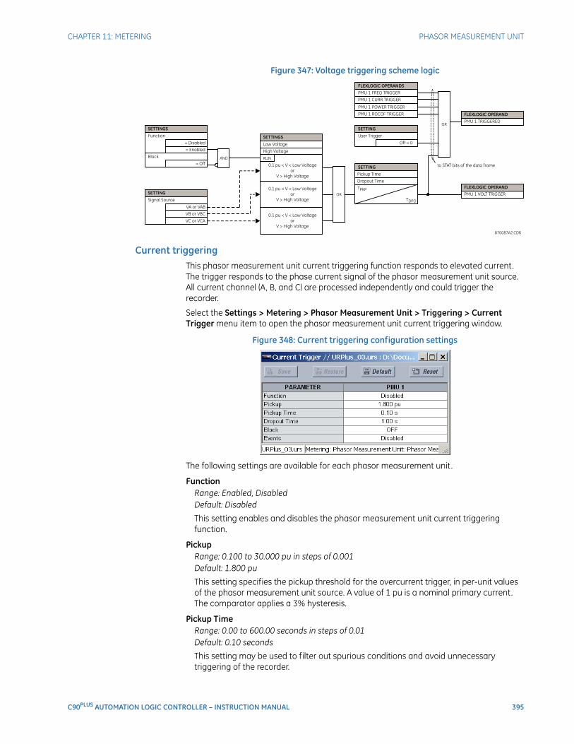
CHAPTER 11: METERING PHASOR MEASUREMENT UNIT
C90PLUS AUTOMATION LOGIC CONTROLLER – INSTRUCTION MANUAL 395
Figure 347: Voltage triggering scheme logic
Current triggeringThis phasor measurement unit current triggering function responds to elevated current. The trigger responds to the phase current signal of the phasor measurement unit source. All current channel (A, B, and C) are processed independently and could trigger the recorder.
Select the Settings > Metering > Phasor Measurement Unit > Triggering > Current Trigger menu item to open the phasor measurement unit current triggering window.
Figure 348: Current triggering configuration settings
The following settings are available for each phasor measurement unit.
FunctionRange: Enabled, DisabledDefault: Disabled
This setting enables and disables the phasor measurement unit current triggering function.
PickupRange: 0.100 to 30.000 pu in steps of 0.001Default: 1.800 pu
This setting specifies the pickup threshold for the overcurrent trigger, in per-unit values of the phasor measurement unit source. A value of 1 pu is a nominal primary current. The comparator applies a 3% hysteresis.
Pickup TimeRange: 0.00 to 600.00 seconds in steps of 0.01Default: 0.10 seconds
This setting may be used to filter out spurious conditions and avoid unnecessary triggering of the recorder.
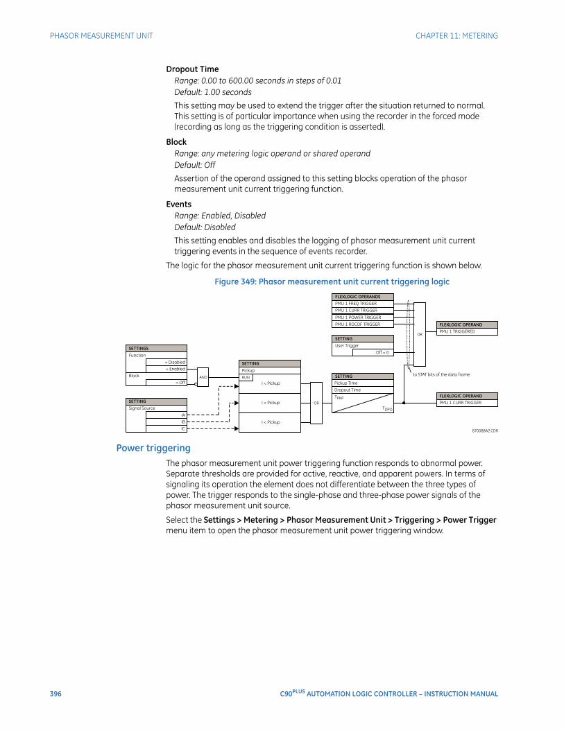
396 C90PLUS AUTOMATION LOGIC CONTROLLER – INSTRUCTION MANUAL
PHASOR MEASUREMENT UNIT CHAPTER 11: METERING
Dropout TimeRange: 0.00 to 600.00 seconds in steps of 0.01Default: 1.00 seconds
This setting may be used to extend the trigger after the situation returned to normal. This setting is of particular importance when using the recorder in the forced mode (recording as long as the triggering condition is asserted).
BlockRange: any metering logic operand or shared operandDefault: Off
Assertion of the operand assigned to this setting blocks operation of the phasor measurement unit current triggering function.
EventsRange: Enabled, DisabledDefault: Disabled
This setting enables and disables the logging of phasor measurement unit current triggering events in the sequence of events recorder.
The logic for the phasor measurement unit current triggering function is shown below.
Figure 349: Phasor measurement unit current triggering logic
Power triggeringThe phasor measurement unit power triggering function responds to abnormal power. Separate thresholds are provided for active, reactive, and apparent powers. In terms of signaling its operation the element does not differentiate between the three types of power. The trigger responds to the single-phase and three-phase power signals of the phasor measurement unit source.
Select the Settings > Metering > Phasor Measurement Unit > Triggering > Power Trigger menu item to open the phasor measurement unit power triggering window.
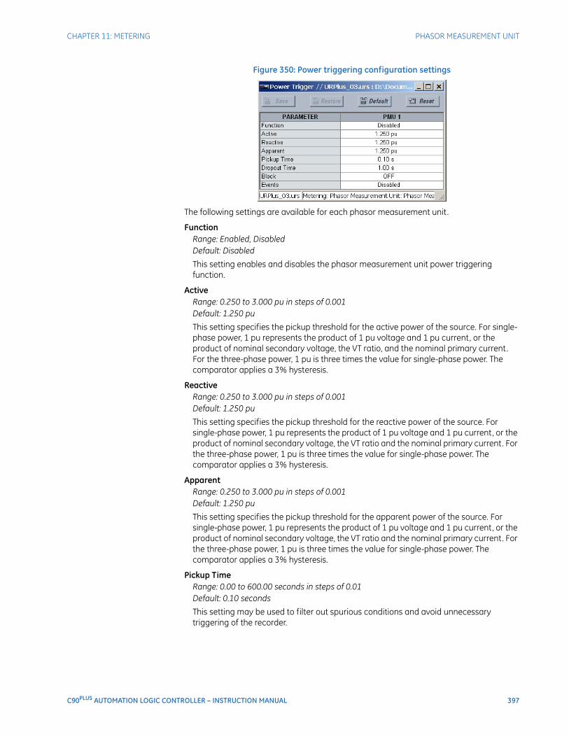
CHAPTER 11: METERING PHASOR MEASUREMENT UNIT
C90PLUS AUTOMATION LOGIC CONTROLLER – INSTRUCTION MANUAL 397
Figure 350: Power triggering configuration settings
The following settings are available for each phasor measurement unit.
FunctionRange: Enabled, DisabledDefault: Disabled
This setting enables and disables the phasor measurement unit power triggering function.
ActiveRange: 0.250 to 3.000 pu in steps of 0.001Default: 1.250 pu
This setting specifies the pickup threshold for the active power of the source. For single-phase power, 1 pu represents the product of 1 pu voltage and 1 pu current, or the product of nominal secondary voltage, the VT ratio, and the nominal primary current. For the three-phase power, 1 pu is three times the value for single-phase power. The comparator applies a 3% hysteresis.
ReactiveRange: 0.250 to 3.000 pu in steps of 0.001Default: 1.250 pu
This setting specifies the pickup threshold for the reactive power of the source. For single-phase power, 1 pu represents the product of 1 pu voltage and 1 pu current, or the product of nominal secondary voltage, the VT ratio and the nominal primary current. For the three-phase power, 1 pu is three times the value for single-phase power. The comparator applies a 3% hysteresis.
ApparentRange: 0.250 to 3.000 pu in steps of 0.001Default: 1.250 pu
This setting specifies the pickup threshold for the apparent power of the source. For single-phase power, 1 pu represents the product of 1 pu voltage and 1 pu current, or the product of nominal secondary voltage, the VT ratio and the nominal primary current. For the three-phase power, 1 pu is three times the value for single-phase power. The comparator applies a 3% hysteresis.
Pickup TimeRange: 0.00 to 600.00 seconds in steps of 0.01Default: 0.10 seconds
This setting may be used to filter out spurious conditions and avoid unnecessary triggering of the recorder.
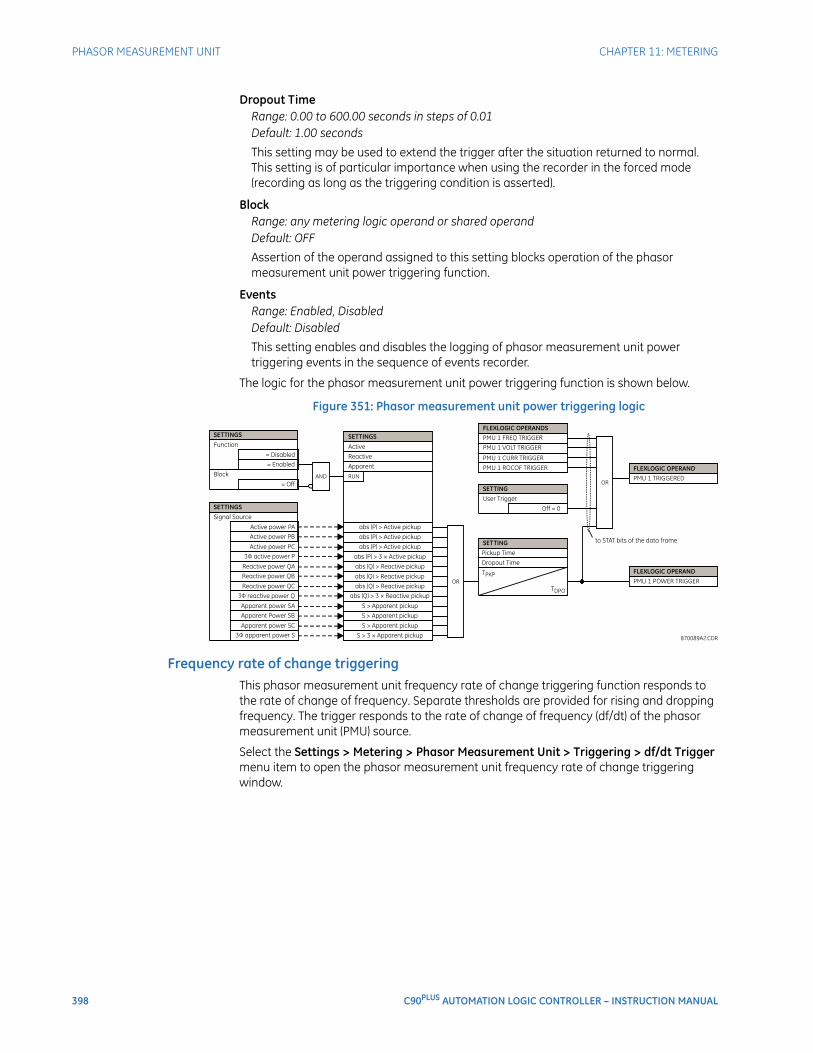
398 C90PLUS AUTOMATION LOGIC CONTROLLER – INSTRUCTION MANUAL
PHASOR MEASUREMENT UNIT CHAPTER 11: METERING
Dropout TimeRange: 0.00 to 600.00 seconds in steps of 0.01Default: 1.00 seconds
This setting may be used to extend the trigger after the situation returned to normal. This setting is of particular importance when using the recorder in the forced mode (recording as long as the triggering condition is asserted).
BlockRange: any metering logic operand or shared operandDefault: OFF
Assertion of the operand assigned to this setting blocks operation of the phasor measurement unit power triggering function.
EventsRange: Enabled, DisabledDefault: Disabled
This setting enables and disables the logging of phasor measurement unit power triggering events in the sequence of events recorder.
The logic for the phasor measurement unit power triggering function is shown below.
Figure 351: Phasor measurement unit power triggering logic
Frequency rate of change triggeringThis phasor measurement unit frequency rate of change triggering function responds to the rate of change of frequency. Separate thresholds are provided for rising and dropping frequency. The trigger responds to the rate of change of frequency (df/dt) of the phasor measurement unit (PMU) source.
Select the Settings > Metering > Phasor Measurement Unit > Triggering > df/dt Trigger menu item to open the phasor measurement unit frequency rate of change triggering window.
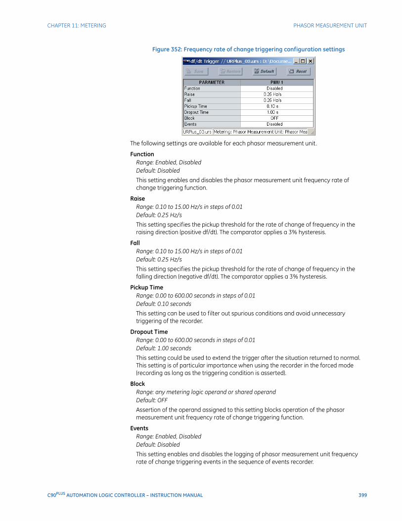
CHAPTER 11: METERING PHASOR MEASUREMENT UNIT
C90PLUS AUTOMATION LOGIC CONTROLLER – INSTRUCTION MANUAL 399
Figure 352: Frequency rate of change triggering configuration settings
The following settings are available for each phasor measurement unit.
FunctionRange: Enabled, DisabledDefault: Disabled
This setting enables and disables the phasor measurement unit frequency rate of change triggering function.
RaiseRange: 0.10 to 15.00 Hz/s in steps of 0.01Default: 0.25 Hz/s
This setting specifies the pickup threshold for the rate of change of frequency in the raising direction (positive df/dt). The comparator applies a 3% hysteresis.
FallRange: 0.10 to 15.00 Hz/s in steps of 0.01Default: 0.25 Hz/s
This setting specifies the pickup threshold for the rate of change of frequency in the falling direction (negative df/dt). The comparator applies a 3% hysteresis.
Pickup TimeRange: 0.00 to 600.00 seconds in steps of 0.01Default: 0.10 seconds
This setting can be used to filter out spurious conditions and avoid unnecessary triggering of the recorder.
Dropout TimeRange: 0.00 to 600.00 seconds in steps of 0.01Default: 1.00 seconds
This setting could be used to extend the trigger after the situation returned to normal. This setting is of particular importance when using the recorder in the forced mode (recording as long as the triggering condition is asserted).
BlockRange: any metering logic operand or shared operandDefault: OFF
Assertion of the operand assigned to this setting blocks operation of the phasor measurement unit frequency rate of change triggering function.
EventsRange: Enabled, DisabledDefault: Disabled
This setting enables and disables the logging of phasor measurement unit frequency rate of change triggering events in the sequence of events recorder.
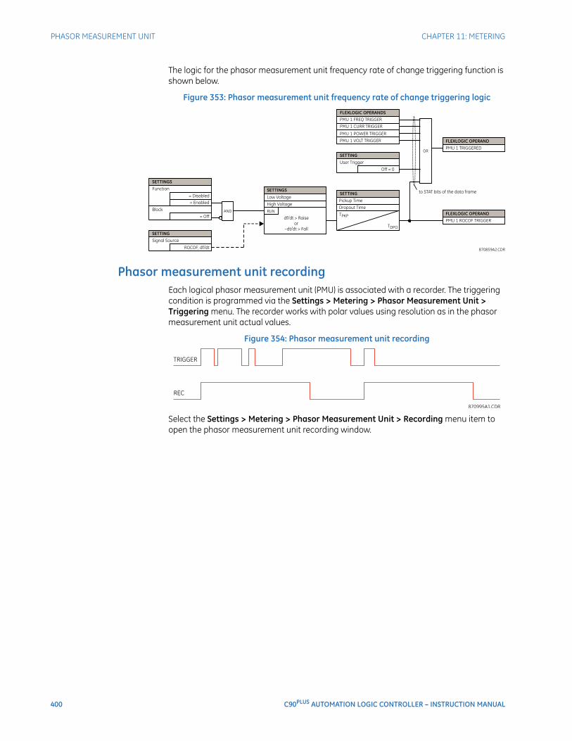
400 C90PLUS AUTOMATION LOGIC CONTROLLER – INSTRUCTION MANUAL
PHASOR MEASUREMENT UNIT CHAPTER 11: METERING
The logic for the phasor measurement unit frequency rate of change triggering function is shown below.
Figure 353: Phasor measurement unit frequency rate of change triggering logic
Phasor measurement unit recordingEach logical phasor measurement unit (PMU) is associated with a recorder. The triggering condition is programmed via the Settings > Metering > Phasor Measurement Unit > Triggering menu. The recorder works with polar values using resolution as in the phasor measurement unit actual values.
Figure 354: Phasor measurement unit recording
Select the Settings > Metering > Phasor Measurement Unit > Recording menu item to open the phasor measurement unit recording window.
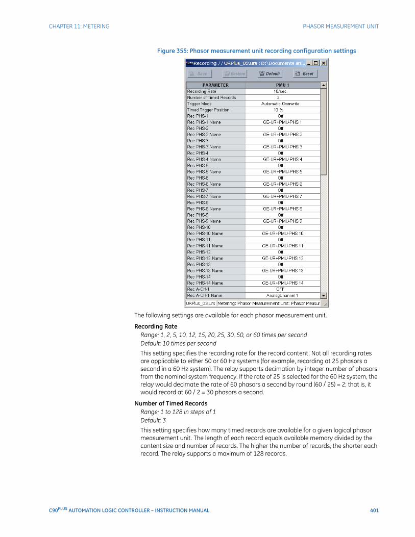
CHAPTER 11: METERING PHASOR MEASUREMENT UNIT
C90PLUS AUTOMATION LOGIC CONTROLLER – INSTRUCTION MANUAL 401
Figure 355: Phasor measurement unit recording configuration settings
The following settings are available for each phasor measurement unit.
Recording RateRange: 1, 2, 5, 10, 12, 15, 20, 25, 30, 50, or 60 times per secondDefault: 10 times per second
This setting specifies the recording rate for the record content. Not all recording rates are applicable to either 50 or 60 Hz systems (for example, recording at 25 phasors a second in a 60 Hz system). The relay supports decimation by integer number of phasors from the nominal system frequency. If the rate of 25 is selected for the 60 Hz system, the relay would decimate the rate of 60 phasors a second by round (60 / 25) = 2; that is, it would record at 60 / 2 = 30 phasors a second.
Number of Timed RecordsRange: 1 to 128 in steps of 1Default: 3
This setting specifies how many timed records are available for a given logical phasor measurement unit. The length of each record equals available memory divided by the content size and number of records. The higher the number of records, the shorter each record. The relay supports a maximum of 128 records.
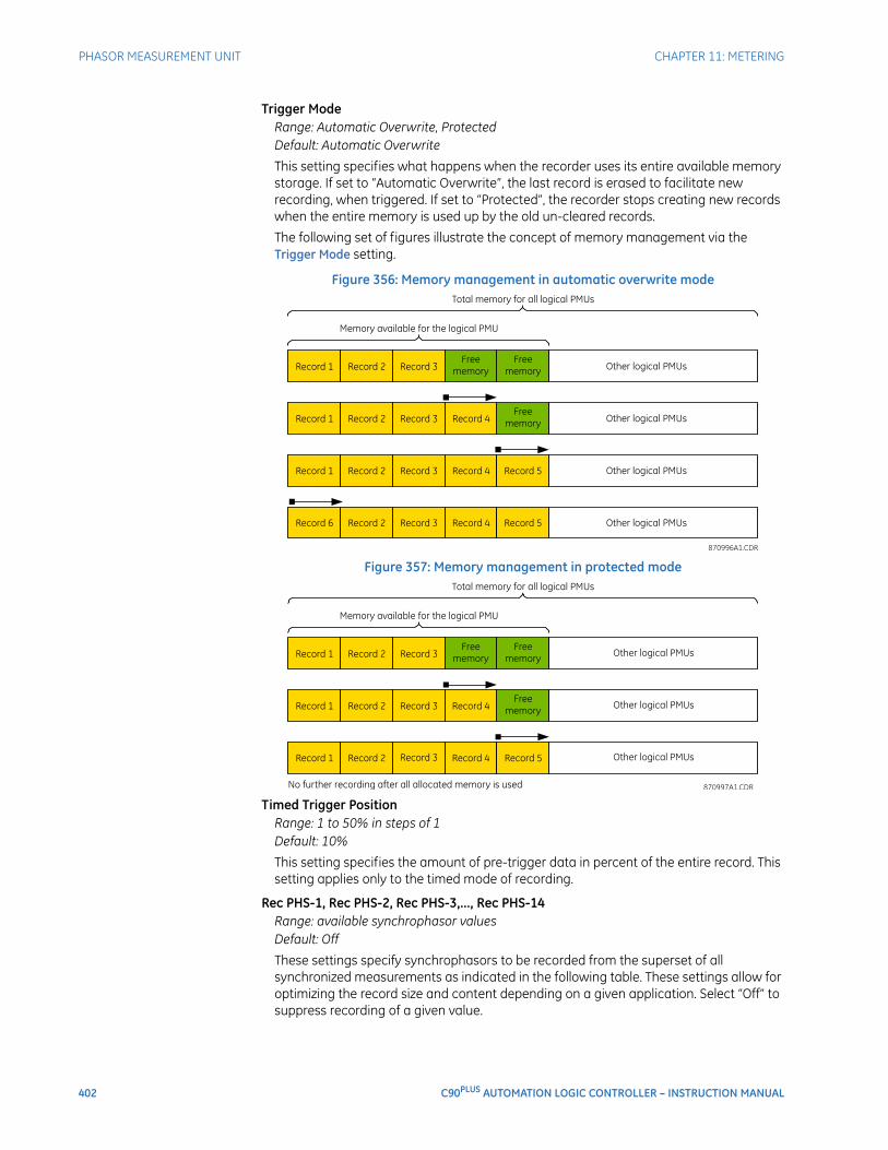
402 C90PLUS AUTOMATION LOGIC CONTROLLER – INSTRUCTION MANUAL
PHASOR MEASUREMENT UNIT CHAPTER 11: METERING
Trigger ModeRange: Automatic Overwrite, ProtectedDefault: Automatic Overwrite
This setting specifies what happens when the recorder uses its entire available memory storage. If set to “Automatic Overwrite”, the last record is erased to facilitate new recording, when triggered. If set to “Protected”, the recorder stops creating new records when the entire memory is used up by the old un-cleared records.
The following set of figures illustrate the concept of memory management via the Trigger Mode setting.
Figure 356: Memory management in automatic overwrite mode
Figure 357: Memory management in protected mode
Timed Trigger PositionRange: 1 to 50% in steps of 1Default: 10%
This setting specifies the amount of pre-trigger data in percent of the entire record. This setting applies only to the timed mode of recording.
Rec PHS-1, Rec PHS-2, Rec PHS-3,..., Rec PHS-14Range: available synchrophasor valuesDefault: Off
These settings specify synchrophasors to be recorded from the superset of all synchronized measurements as indicated in the following table. These settings allow for optimizing the record size and content depending on a given application. Select “Off” to suppress recording of a given value.
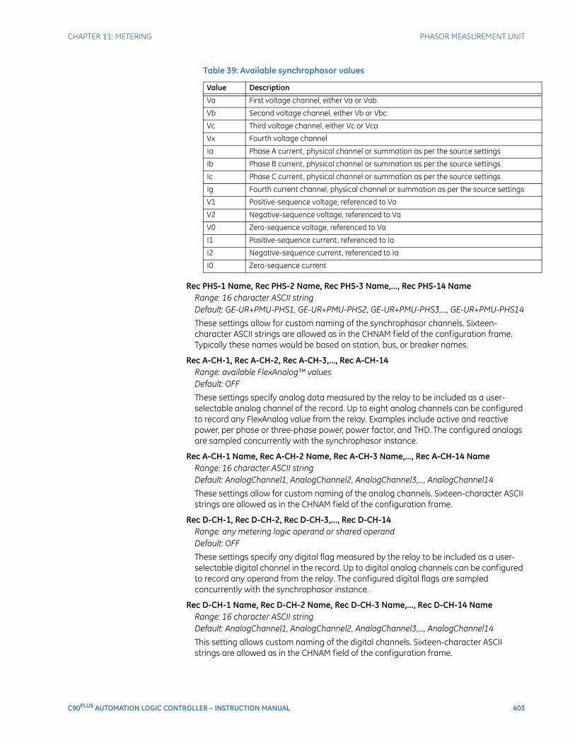
CHAPTER 11: METERING PHASOR MEASUREMENT UNIT
C90PLUS AUTOMATION LOGIC CONTROLLER – INSTRUCTION MANUAL 403
Table 39: Available synchrophasor values
Rec PHS-1 Name, Rec PHS-2 Name, Rec PHS-3 Name,..., Rec PHS-14 NameRange: 16 character ASCII stringDefault: GE-UR+PMU-PHS1, GE-UR+PMU-PHS2, GE-UR+PMU-PHS3,..., GE-UR+PMU-PHS14
These settings allow for custom naming of the synchrophasor channels. Sixteen-character ASCII strings are allowed as in the CHNAM field of the configuration frame. Typically these names would be based on station, bus, or breaker names.
Rec A-CH-1, Rec A-CH-2, Rec A-CH-3,..., Rec A-CH-14Range: available FlexAnalog™ valuesDefault: OFF
These settings specify analog data measured by the relay to be included as a user-selectable analog channel of the record. Up to eight analog channels can be configured to record any FlexAnalog value from the relay. Examples include active and reactive power, per phase or three-phase power, power factor, and THD. The configured analogs are sampled concurrently with the synchrophasor instance.
Rec A-CH-1 Name, Rec A-CH-2 Name, Rec A-CH-3 Name,..., Rec A-CH-14 NameRange: 16 character ASCII stringDefault: AnalogChannel1, AnalogChannel2, AnalogChannel3,..., AnalogChannel14
These settings allow for custom naming of the analog channels. Sixteen-character ASCII strings are allowed as in the CHNAM field of the configuration frame.
Rec D-CH-1, Rec D-CH-2, Rec D-CH-3,..., Rec D-CH-14Range: any metering logic operand or shared operandDefault: OFF
These settings specify any digital flag measured by the relay to be included as a user-selectable digital channel in the record. Up to digital analog channels can be configured to record any operand from the relay. The configured digital flags are sampled concurrently with the synchrophasor instance.
Rec D-CH-1 Name, Rec D-CH-2 Name, Rec D-CH-3 Name,..., Rec D-CH-14 NameRange: 16 character ASCII stringDefault: AnalogChannel1, AnalogChannel2, AnalogChannel3,..., AnalogChannel14
This setting allows custom naming of the digital channels. Sixteen-character ASCII strings are allowed as in the CHNAM field of the configuration frame.
Value Description
Va First voltage channel, either Va or Vab
Vb Second voltage channel, either Vb or Vbc
Vc Third voltage channel, either Vc or Vca
Vx Fourth voltage channel
Ia Phase A current, physical channel or summation as per the source settings
Ib Phase B current, physical channel or summation as per the source settings
Ic Phase C current, physical channel or summation as per the source settings
Ig Fourth current channel, physical channel or summation as per the source settings
V1 Positive-sequence voltage, referenced to Va
V2 Negative-sequence voltage, referenced to Va
V0 Zero-sequence voltage, referenced to Va
I1 Positive-sequence current, referenced to Ia
I2 Negative-sequence current, referenced to Ia
I0 Zero-sequence current
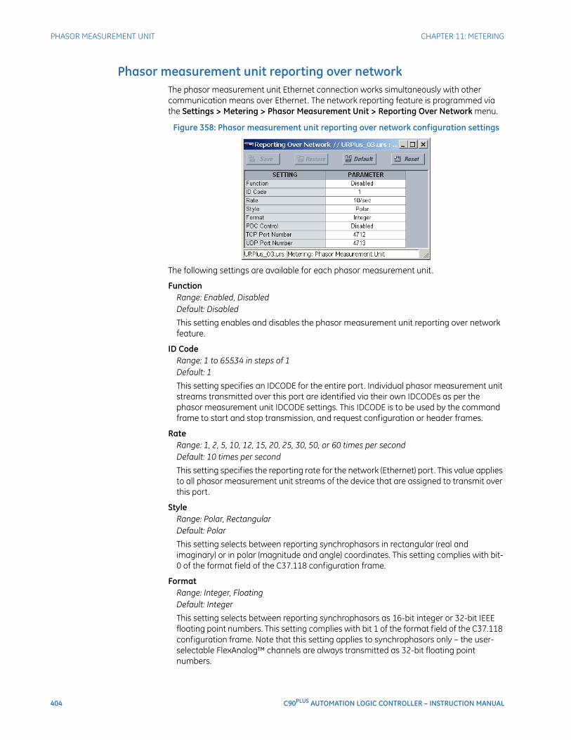
404 C90PLUS AUTOMATION LOGIC CONTROLLER – INSTRUCTION MANUAL
PHASOR MEASUREMENT UNIT CHAPTER 11: METERING
Phasor measurement unit reporting over networkThe phasor measurement unit Ethernet connection works simultaneously with other communication means over Ethernet. The network reporting feature is programmed via the Settings > Metering > Phasor Measurement Unit > Reporting Over Network menu.
Figure 358: Phasor measurement unit reporting over network configuration settings
The following settings are available for each phasor measurement unit.
FunctionRange: Enabled, DisabledDefault: Disabled
This setting enables and disables the phasor measurement unit reporting over network feature.
ID CodeRange: 1 to 65534 in steps of 1Default: 1
This setting specifies an IDCODE for the entire port. Individual phasor measurement unit streams transmitted over this port are identified via their own IDCODEs as per the phasor measurement unit IDCODE settings. This IDCODE is to be used by the command frame to start and stop transmission, and request configuration or header frames.
RateRange: 1, 2, 5, 10, 12, 15, 20, 25, 30, 50, or 60 times per secondDefault: 10 times per second
This setting specifies the reporting rate for the network (Ethernet) port. This value applies to all phasor measurement unit streams of the device that are assigned to transmit over this port.
StyleRange: Polar, RectangularDefault: Polar
This setting selects between reporting synchrophasors in rectangular (real and imaginary) or in polar (magnitude and angle) coordinates. This setting complies with bit-0 of the format field of the C37.118 configuration frame.
FormatRange: Integer, FloatingDefault: Integer
This setting selects between reporting synchrophasors as 16-bit integer or 32-bit IEEE floating point numbers. This setting complies with bit 1 of the format field of the C37.118 configuration frame. Note that this setting applies to synchrophasors only – the user-selectable FlexAnalog™ channels are always transmitted as 32-bit floating point numbers.
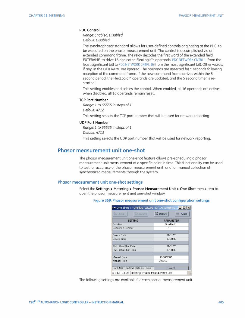
CHAPTER 11: METERING PHASOR MEASUREMENT UNIT
C90PLUS AUTOMATION LOGIC CONTROLLER – INSTRUCTION MANUAL 405
PDC ControlRange: Enabled, DisabledDefault: Disabled
The synchrophasor standard allows for user-defined controls originating at the PDC, to be executed on the phasor measurement unit. The control is accomplished via an extended command frame. The relay decodes the first word of the extended field, EXTFRAME, to drive 16 dedicated FlexLogic™ operands: PDC NETWORK CNTRL 1 (from the least significant bit) to PDC NETWORK CNTRL 16 (from the most significant bit). Other words, if any, in the EXTFRAME are ignored. The operands are asserted for 5 seconds following reception of the command frame. If the new command frame arrives within the 5 second period, the FlexLogic™ operands are updated, and the 5 second timer is re-started.
This setting enables or disables the control. When enabled, all 16 operands are active; when disabled, all 16 operands remain reset.
TCP Port NumberRange: 1 to 65535 in steps of 1Default: 4712
This setting selects the TCP port number that will be used for network reporting.
UDP Port NumberRange: 1 to 65535 in steps of 1Default: 4713
This setting selects the UDP port number that will be used for network reporting.
Phasor measurement unit one-shotThe phasor measurement unit one-shot feature allows pre-scheduling a phasor measurement unit measurement at a specific point in time. This functionality can be used to test for accuracy of the phasor measurement unit, and for manual collection of synchronized measurements through the system.
Phasor measurement unit one-shot settingsSelect the Settings > Metering > Phasor Measurement Unit > One-Shot menu item to open the phasor measurement unit one-shot window.
Figure 359: Phasor measurement unit one-shot configuration settings
The following settings are available for each phasor measurement unit.
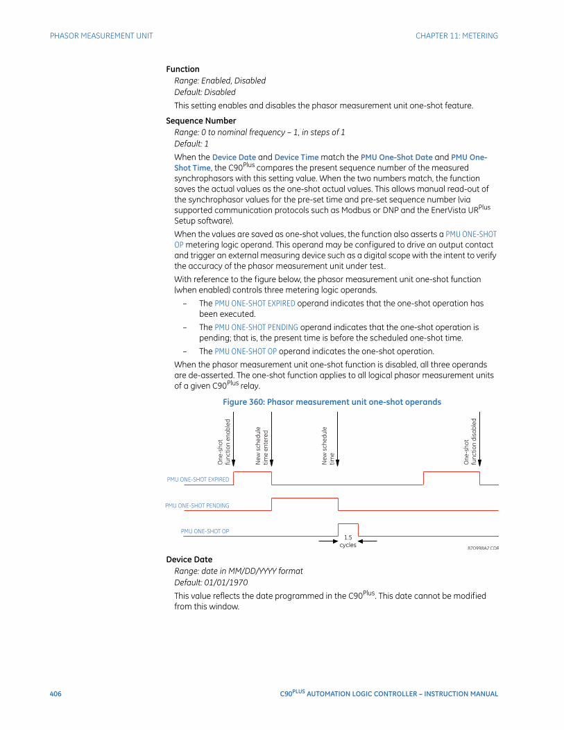
406 C90PLUS AUTOMATION LOGIC CONTROLLER – INSTRUCTION MANUAL
PHASOR MEASUREMENT UNIT CHAPTER 11: METERING
FunctionRange: Enabled, DisabledDefault: Disabled
This setting enables and disables the phasor measurement unit one-shot feature.
Sequence NumberRange: 0 to nominal frequency – 1, in steps of 1Default: 1
When the Device Date and Device Time match the PMU One-Shot Date and PMU One-Shot Time, the C90Plus compares the present sequence number of the measured synchrophasors with this setting value. When the two numbers match, the function saves the actual values as the one-shot actual values. This allows manual read-out of the synchrophasor values for the pre-set time and pre-set sequence number (via supported communication protocols such as Modbus or DNP and the EnerVista URPlus Setup software).
When the values are saved as one-shot values, the function also asserts a PMU ONE-SHOT OP metering logic operand. This operand may be configured to drive an output contact and trigger an external measuring device such as a digital scope with the intent to verify the accuracy of the phasor measurement unit under test.
With reference to the figure below, the phasor measurement unit one-shot function (when enabled) controls three metering logic operands.
– The PMU ONE-SHOT EXPIRED operand indicates that the one-shot operation has been executed.
– The PMU ONE-SHOT PENDING operand indicates that the one-shot operation is pending; that is, the present time is before the scheduled one-shot time.
– The PMU ONE-SHOT OP operand indicates the one-shot operation.
When the phasor measurement unit one-shot function is disabled, all three operands are de-asserted. The one-shot function applies to all logical phasor measurement units of a given C90Plus relay.
Figure 360: Phasor measurement unit one-shot operands
Device DateRange: date in MM/DD/YYYY formatDefault: 01/01/1970
This value reflects the date programmed in the C90Plus. This date cannot be modified from this window.

CHAPTER 11: METERING PHASOR MEASUREMENT UNIT
C90PLUS AUTOMATION LOGIC CONTROLLER – INSTRUCTION MANUAL 407
Device TimeRange: time in HH:MM:SS formatDefault: 00:00:00
This value reflects the time programmed in the C90Plus. This time cannot be modified from this window.
PMU One-Shot DateRange: date in MM/DD/YYYY formatDefault: 01/01/2007
When the phasor measurement unit one-shot feature is enabled, the C90Plus continuously compares the device date with this value.
PMU One-Shot TimeRange: time in HH:MM:SS formatDefault: 00:00:00
When the phasor measurement unit one-shot feature is enabled, the C90Plus continuously compares the device date with this value.
Manual DateRange: date in MM/DD/YYYY formatDefault: 01/01/2007
The PMU One-Shot Date will be updated to the value specified by this setting when the Set PMU One-Shot Date and Time command is executed.
Manual TimeRange: time in HH:MM:SS formatDefault: 00:00:00
The PMU One-Shot Time will be updated to the value specified by this setting when the Set PMU One-Shot Date and Time command is executed.
Testing the accuracy of the phasor measurement unitThe phasor measurement unit one-shot feature can be used to test accuracy of the synchrophasor measurement. GPS-synchronized tests sets perform a similar function to PMUs: instead of measuring the phasor from physical signals with respect to the externally provided time reference, they produce the physical signals with respect to the externally provided time reference, given the desired phasor values. Therefore the GPS-synchronized test sets cannot be automatically assumed more accurate then the phasor measurement units under test. This calls for a method to verify both the measuring device (PMU) and the source of signal (test set).
With reference to the figure below, the one-shot feature could be configured to trigger a high-accuracy scope to capture both the time reference signal (rising edge of the 1 pps signal of the IRIG-B time reference), and the measured waveform. The high-accuracy high-sampling rate record of the two signals captured by the scope can be processed using digital tools to verify the magnitude and phase angle with respect to the time reference signal. As both the time reference and the measured signals are raw inputs to the phasor measurement unit under test, their independently captured record, processed using third-party software, is a good reference point for accuracy calculations. Such a record proves useful when discussing the test results, and should be retained as a part of the testing documentation.
Note that the phasor measurement unit under test does not have to be connected to a real GPS receiver as the accuracy is measured with respect to the timing reference provided to the phasor measurement unit and not to the absolute UTC time. Therefore a simple IRIG-B generator could be used instead. Also, the test set does not have to support GPS synchronization. Any stable signal source can be used. If both the phasor measurement unit under test and the test set use the timing reference, they should be driven from the
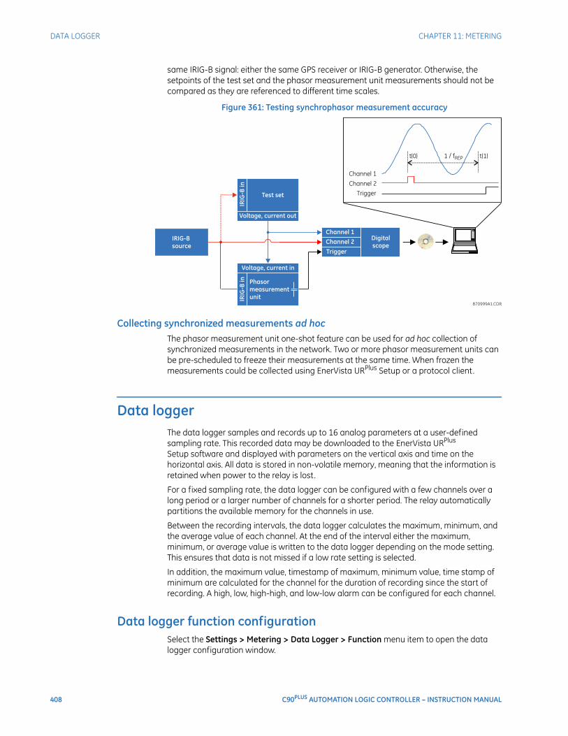
408 C90PLUS AUTOMATION LOGIC CONTROLLER – INSTRUCTION MANUAL
DATA LOGGER CHAPTER 11: METERING
same IRIG-B signal: either the same GPS receiver or IRIG-B generator. Otherwise, the setpoints of the test set and the phasor measurement unit measurements should not be compared as they are referenced to different time scales.
Figure 361: Testing synchrophasor measurement accuracy
Collecting synchronized measurements ad hocThe phasor measurement unit one-shot feature can be used for ad hoc collection of synchronized measurements in the network. Two or more phasor measurement units can be pre-scheduled to freeze their measurements at the same time. When frozen the measurements could be collected using EnerVista URPlus Setup or a protocol client.
Data loggerThe data logger samples and records up to 16 analog parameters at a user-defined sampling rate. This recorded data may be downloaded to the EnerVista URPlus Setup software and displayed with parameters on the vertical axis and time on the horizontal axis. All data is stored in non-volatile memory, meaning that the information is retained when power to the relay is lost.
For a fixed sampling rate, the data logger can be configured with a few channels over a long period or a larger number of channels for a shorter period. The relay automatically partitions the available memory for the channels in use.
Between the recording intervals, the data logger calculates the maximum, minimum, and the average value of each channel. At the end of the interval either the maximum, minimum, or average value is written to the data logger depending on the mode setting. This ensures that data is not missed if a low rate setting is selected.
In addition, the maximum value, timestamp of maximum, minimum value, time stamp of minimum are calculated for the channel for the duration of recording since the start of recording. A high, low, high-high, and low-low alarm can be configured for each channel.
Data logger function configurationSelect the Settings > Metering > Data Logger > Function menu item to open the data logger configuration window.
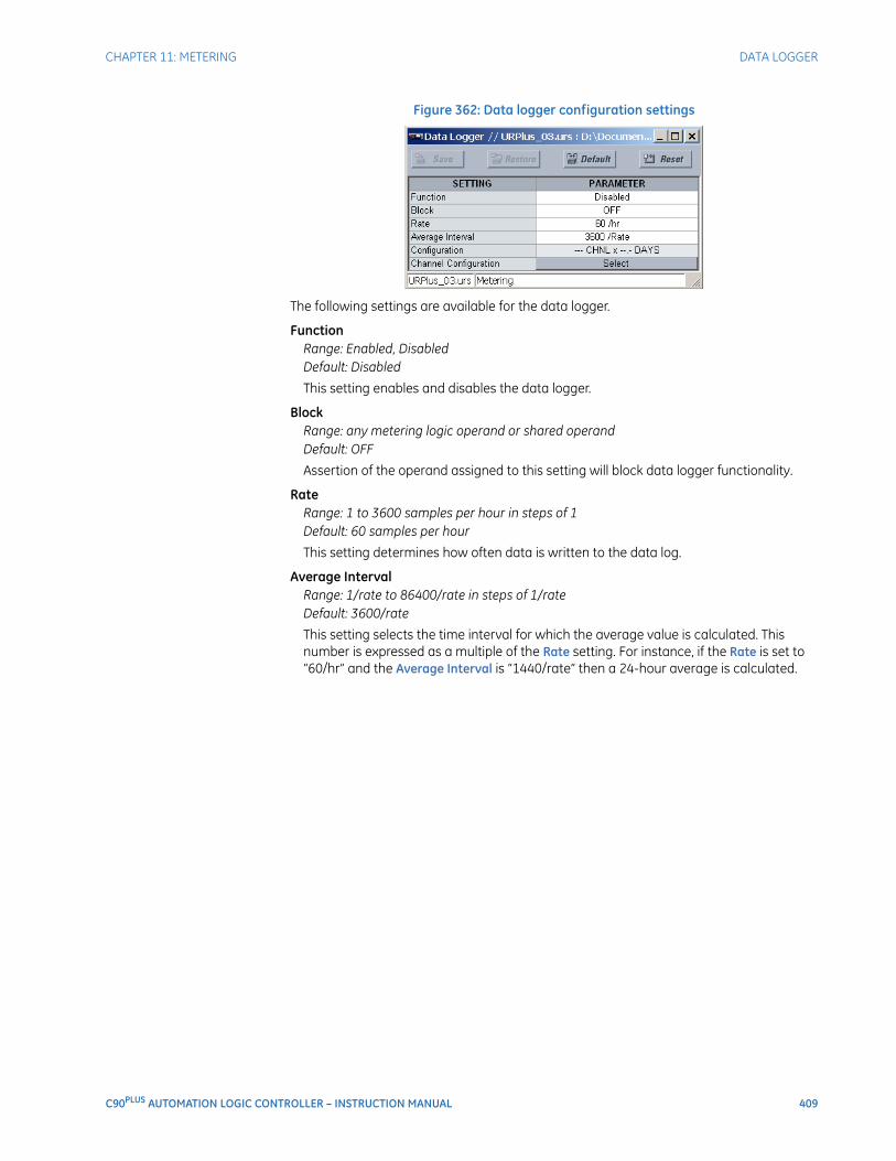
CHAPTER 11: METERING DATA LOGGER
C90PLUS AUTOMATION LOGIC CONTROLLER – INSTRUCTION MANUAL 409
Figure 362: Data logger configuration settings
The following settings are available for the data logger.
FunctionRange: Enabled, DisabledDefault: Disabled
This setting enables and disables the data logger.
BlockRange: any metering logic operand or shared operandDefault: OFF
Assertion of the operand assigned to this setting will block data logger functionality.
RateRange: 1 to 3600 samples per hour in steps of 1Default: 60 samples per hour
This setting determines how often data is written to the data log.
Average IntervalRange: 1/rate to 86400/rate in steps of 1/rateDefault: 3600/rate
This setting selects the time interval for which the average value is calculated. This number is expressed as a multiple of the Rate setting. For instance, if the Rate is set to “60/hr” and the Average Interval is “1440/rate” then a 24-hour average is calculated.
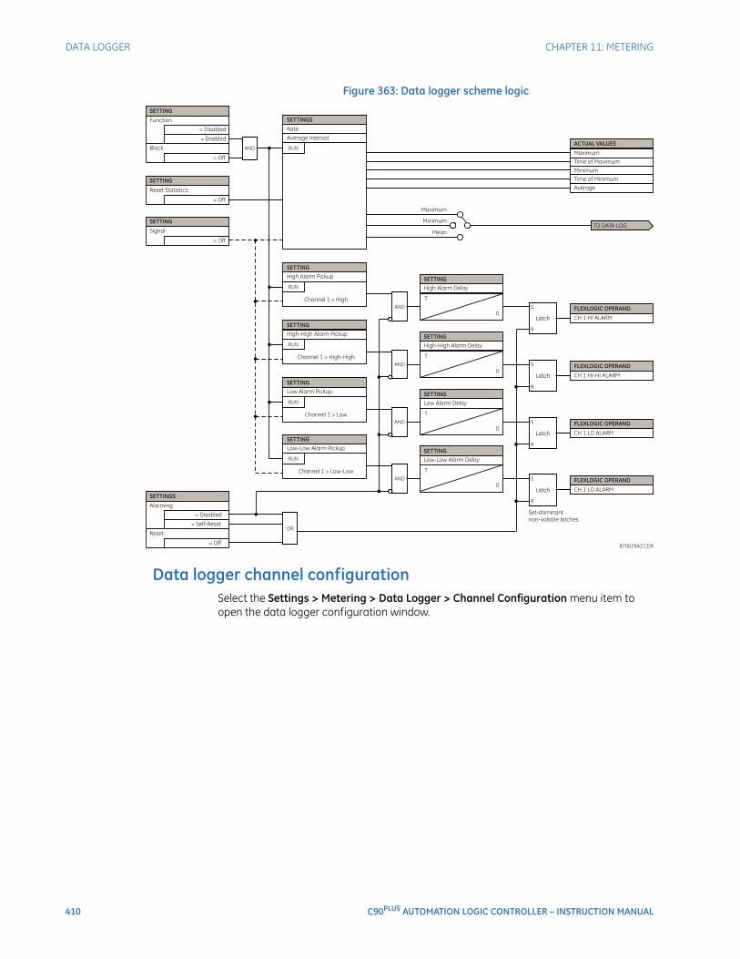
410 C90PLUS AUTOMATION LOGIC CONTROLLER – INSTRUCTION MANUAL
DATA LOGGER CHAPTER 11: METERING
Figure 363: Data logger scheme logic
Data logger channel configurationSelect the Settings > Metering > Data Logger > Channel Configuration menu item to open the data logger configuration window.
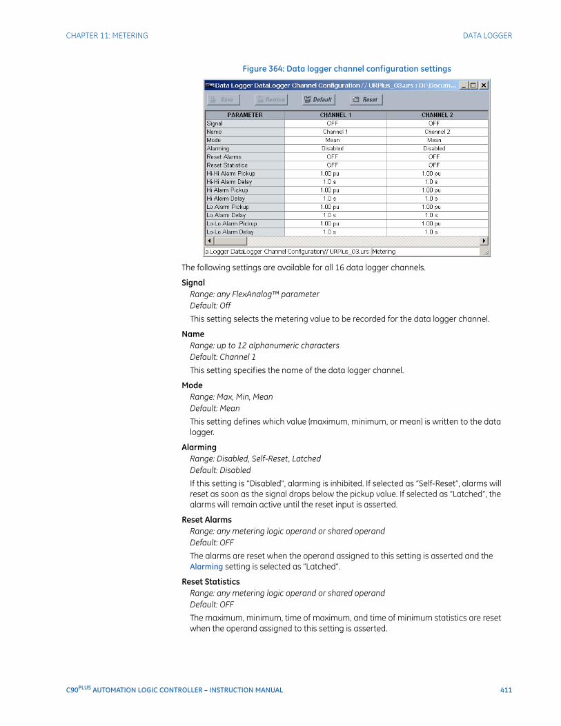
CHAPTER 11: METERING DATA LOGGER
C90PLUS AUTOMATION LOGIC CONTROLLER – INSTRUCTION MANUAL 411
Figure 364: Data logger channel configuration settings
The following settings are available for all 16 data logger channels.
SignalRange: any FlexAnalog™ parameterDefault: Off
This setting selects the metering value to be recorded for the data logger channel.
NameRange: up to 12 alphanumeric charactersDefault: Channel 1
This setting specifies the name of the data logger channel.
ModeRange: Max, Min, MeanDefault: Mean
This setting defines which value (maximum, minimum, or mean) is written to the data logger.
AlarmingRange: Disabled, Self-Reset, LatchedDefault: Disabled
If this setting is “Disabled”, alarming is inhibited. If selected as “Self-Reset”, alarms will reset as soon as the signal drops below the pickup value. If selected as “Latched”, the alarms will remain active until the reset input is asserted.
Reset AlarmsRange: any metering logic operand or shared operandDefault: OFF
The alarms are reset when the operand assigned to this setting is asserted and the Alarming setting is selected as “Latched”.
Reset StatisticsRange: any metering logic operand or shared operandDefault: OFF
The maximum, minimum, time of maximum, and time of minimum statistics are reset when the operand assigned to this setting is asserted.

412 C90PLUS AUTOMATION LOGIC CONTROLLER – INSTRUCTION MANUAL
SHARED OPERANDS CHAPTER 11: METERING
High Alarm Pickup, Low Alarm Pickup, High-High Alarm Pickup, Low-Low Alarm PickupRange: –90.00 to 90.00 pu in steps of 0.01Default: 1.00 pu
These settings specify the pickup thresholds for the alarm in per-unit values. A fixed hysteresis of 3% is applied.
High Alarm Delay, Low Alarm Delay, High-High Alarm Delay, Low-Low Alarm DelayRange: 1.0 to 300.0 seconds in steps of 0.1Default: 1.0 seconds
These settings specify the time delays for the four alarm pickup types.
Shared operandsThe EnerVista URPlus Setup software groups the C90Plus system into the following seven primary functions. Each function has its own setting parameters and each generates its own outputs in the form of operands.
• Protection.
• Automation.
• Metering.
• Communications.
• Digital fault recorder (DFR).
• Equipment manager.
• Front panel interface (HMI).
However, it is often desirable for an output from an element within one function can be available to an element within another function. For instance, it may be useful for the digital fault recorder to record the output operands of any protection element. Consequently a fixed, predetermined set of operands is available as to each function as shown below.
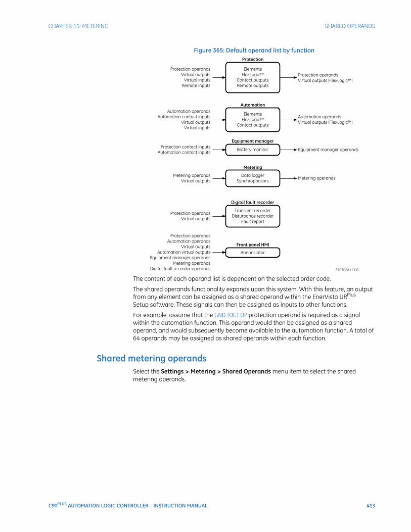
CHAPTER 11: METERING SHARED OPERANDS
C90PLUS AUTOMATION LOGIC CONTROLLER – INSTRUCTION MANUAL 413
Figure 365: Default operand list by function
The content of each operand list is dependent on the selected order code.
The shared operands functionality expands upon this system. With this feature, an output from any element can be assigned as a shared operand within the EnerVista URPlus Setup software. These signals can then be assigned as inputs to other functions.
For example, assume that the GND TOC1 OP protection operand is required as a signal within the automation function. This operand would then be assigned as a shared operand, and would subsequently become available to the automation function. A total of 64 operands may be assigned as shared operands within each function.
Shared metering operandsSelect the Settings > Metering > Shared Operands menu item to select the shared metering operands.
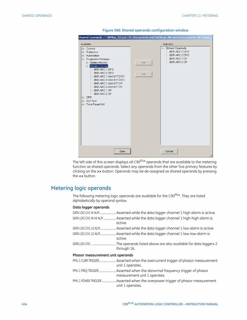
414 C90PLUS AUTOMATION LOGIC CONTROLLER – INSTRUCTION MANUAL
SHARED OPERANDS CHAPTER 11: METERING
Figure 366: Shared operands configuration window
The left side of this screen displays all C90Plus operands that are available to the metering function as shared operands. Select any operands from the other five primary features by clicking on the >> button. Operands may be de-assigned as shared operands by pressing the << button.
Metering logic operandsThe following metering logic operands are available for the C90Plus. They are listed alphabetically by operand syntax.
Data logger operandsDATA LOG CH1 HI ALM.............................Asserted while the data logger channel 1 high alarm is active.DATA LOG CH1 HI-HI ALM ......................Asserted while the data logger channel 1 high-high alarm is
active.DATA LOG CH1 LO ALM............................Asserted while the data logger channel 1 low alarm is active.DATA LOG CH1 LO ALM............................Asserted while the data logger channel 1 low-low alarm is
active.DATA LOG CH2 ... ......................................... The operands listed above are also available for data loggers 2
through 16.
Phasor measurement unit operandsPMU 1 CURR TRIGGER..............................Asserted when the overcurrent trigger of phasor measurement
unit 1 operates.PMU 1 FREQ TRIGGER ..............................Asserted when the abnormal frequency trigger of phasor
measurement unit 1 operates.PMU 1 POWER TRIGGER .........................Asserted when the overpower trigger of phasor measurement
unit 1 operates.

CHAPTER 11: METERING SHARED OPERANDS
C90PLUS AUTOMATION LOGIC CONTROLLER – INSTRUCTION MANUAL 415
PMU 1 ROCOF TRIGGER...........................Asserted when the rate of change of frequency trigger of phasor measurement unit 1 operates.
PMU 1 VOLT TRIGGER ...............................Asserted when the abnormal voltage trigger of phasor measurement unit 1 operates.
PMU 1 TRIGGERED.....................................Asserted when the phasor measurement unit 1 triggers. No events or targets are generated by this operand.
Phasor measurement unit one-shot operandsPMU ONE-SHOT EXPIRED .......................Asserted after the one-shot operation executes.PMU ONE-SHOT OP ...................................Asserted upon one-shot operation.PMU ONE-SHOT PENDING......................Asserted while the one-shot operation is pending. That is, while
the present time is before the scheduled one-shot time.

416 C90PLUS AUTOMATION LOGIC CONTROLLER – INSTRUCTION MANUAL
SHARED OPERANDS CHAPTER 11: METERING
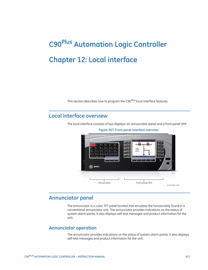
C90PLUS AUTOMATION LOGIC CONTROLLER – INSTRUCTION MANUAL 417
C90Plus Automation Logic Controller
Chapter 12: Local interface
Local interface
This section describes how to program the C90Plus local interface features.
Local interface overviewThe local interface consists of two displays: an annunciator panel and a front panel HMI.
Figure 367: Front panel interface overview
Annunciator panelThe annunciator is a color, TFT panel located that emulates the functionality found in a conventional annunciator unit. The annunciator provides indications on the status of system alarm points. It also displays self-test messages and product information for the unit.
Annunciator operationThe annunciator provides indications on the status of system alarm points. It also displays self-test messages and product information for the unit.
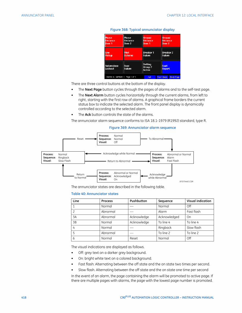
418 C90PLUS AUTOMATION LOGIC CONTROLLER – INSTRUCTION MANUAL
ANNUNCIATOR PANEL CHAPTER 12: LOCAL INTERFACE
Figure 368: Typical annunciator display
There are three control buttons at the bottom of the display.
• The Next Page button cycles through the pages of alarms and to the self-test page.
• The Next Alarm button cycles horizontally through the current alarms, from left to right, starting with the first row of alarms. A graphical frame borders the current status box to indicate the selected alarm. The front panel display is dynamically controlled according to the selected alarm.
• The Ack button controls the state of the alarms.
The annunciator alarm sequence conforms to ISA 18.1-1979 (R1992) standard, type R.
Figure 369: Annunciator alarm sequence
The annunciator states are described in the following table.
Table 40: Annunciator states
The visual indications are displayed as follows.
• Off: grey text on a darker grey background.
• On: bright white text on a colored background.
• Fast flash: Alternating between the off state and the on state two times per second.
• Slow flash. Alternating between the off state and the on state one time per second
In the event of an alarm, the page containing the alarm will be promoted to active page. If there are multiple pages with alarms, the page with the lowest page number is promoted.
Line Process Pushbutton Sequence Visual indication
1 Normal --- Normal Off
2 Abnormal --- Alarm Fast flash
3A Abnormal Acknowledge Acknowledged On
3B Normal Acknowledge To line 4 To line 4
4 Normal --- Ringback Slow flash
5 Abnormal --- To line 2 To line 2
6 Normal Reset Normal Off
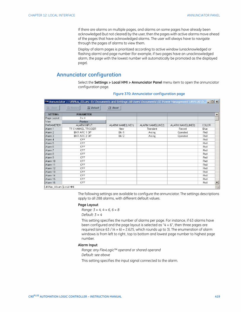
CHAPTER 12: LOCAL INTERFACE ANNUNCIATOR PANEL
C90PLUS AUTOMATION LOGIC CONTROLLER – INSTRUCTION MANUAL 419
If there are alarms on multiple pages, and alarms on some pages have already been acknowledged (but not cleared) by the user, then the pages with active alarms move ahead of the pages that have acknowledged alarms. The user will always have to navigate through the pages of alarms to view them.
Display of alarm pages is prioritized according to active window (unacknowledged or flashing alarm) and page number (for example, if two pages have an unacknowledged alarm, the page with the lowest number will automatically be promoted as the displayed page).
Annunciator configurationSelect the Settings > Local HMI > Annunciator Panel menu item to open the annunciator configuration page.
Figure 370: Annunciator configuration page
The following settings are available to configure the annunciator. The settings descriptions apply to all 288 alarms, with different default values.
Page LayoutRange: 3 × 4, 4 × 6, 6 × 8Default: 3 × 4
This setting specifies the number of alarms per page. For instance, if 63 alarms have been configured and the page layout is selected as “4 × 6”, then three pages are required (since 63 / (4 × 6) = 2.625, which rounds up to 3). The enumeration of alarm windows is from left to right, top to bottom and lowest page number to highest page number.
Alarm InputRange: any FlexLogic™ operand or shared operandDefault: see above
This setting specifies the input signal connected to the alarm.
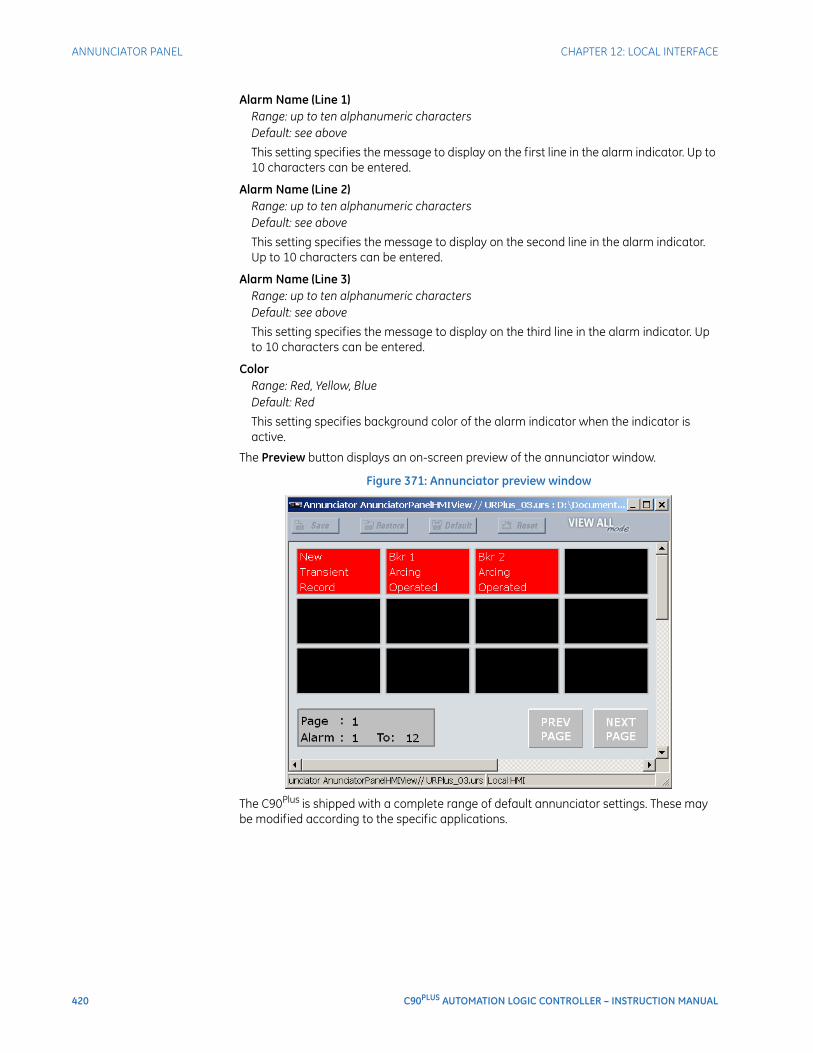
420 C90PLUS AUTOMATION LOGIC CONTROLLER – INSTRUCTION MANUAL
ANNUNCIATOR PANEL CHAPTER 12: LOCAL INTERFACE
Alarm Name (Line 1)Range: up to ten alphanumeric charactersDefault: see above
This setting specifies the message to display on the first line in the alarm indicator. Up to 10 characters can be entered.
Alarm Name (Line 2)Range: up to ten alphanumeric charactersDefault: see above
This setting specifies the message to display on the second line in the alarm indicator. Up to 10 characters can be entered.
Alarm Name (Line 3)Range: up to ten alphanumeric charactersDefault: see above
This setting specifies the message to display on the third line in the alarm indicator. Up to 10 characters can be entered.
ColorRange: Red, Yellow, BlueDefault: Red
This setting specifies background color of the alarm indicator when the indicator is active.
The Preview button displays an on-screen preview of the annunciator window.
Figure 371: Annunciator preview window
The C90Plus is shipped with a complete range of default annunciator settings. These may be modified according to the specific applications.
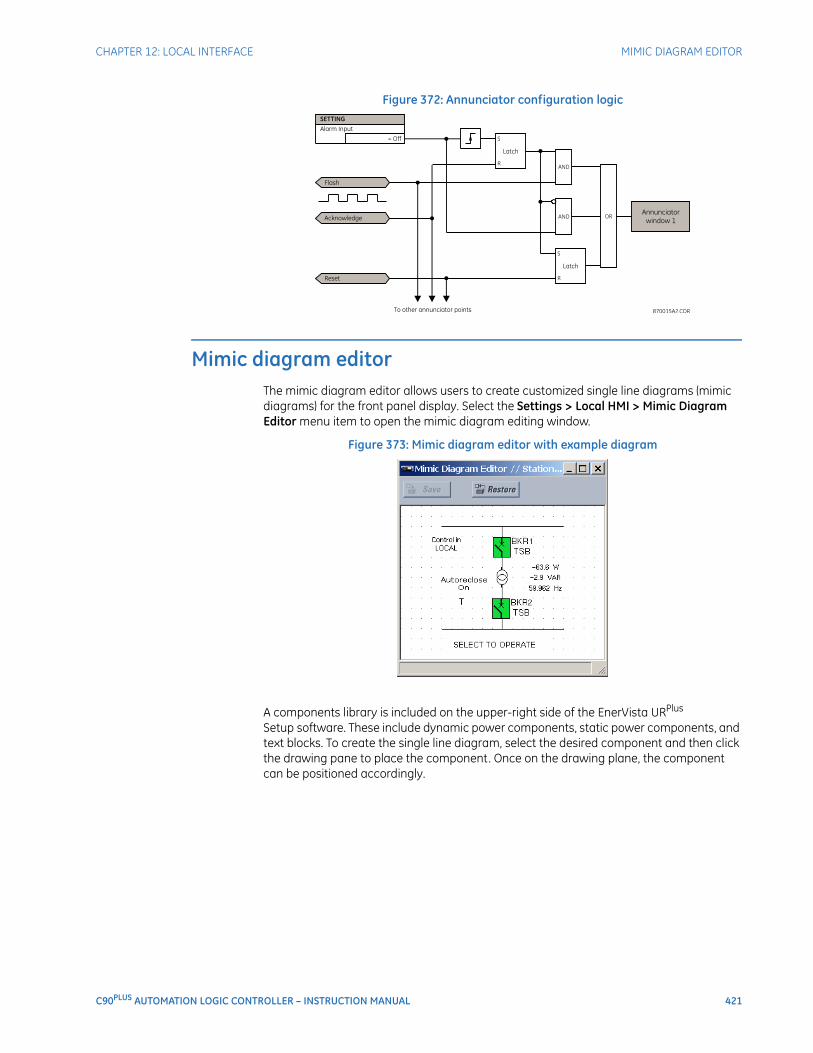
CHAPTER 12: LOCAL INTERFACE MIMIC DIAGRAM EDITOR
C90PLUS AUTOMATION LOGIC CONTROLLER – INSTRUCTION MANUAL 421
Figure 372: Annunciator configuration logic
Mimic diagram editorThe mimic diagram editor allows users to create customized single line diagrams (mimic diagrams) for the front panel display. Select the Settings > Local HMI > Mimic Diagram Editor menu item to open the mimic diagram editing window.
Figure 373: Mimic diagram editor with example diagram
A components library is included on the upper-right side of the EnerVista URPlus Setup software. These include dynamic power components, static power components, and text blocks. To create the single line diagram, select the desired component and then click the drawing pane to place the component. Once on the drawing plane, the component can be positioned accordingly.
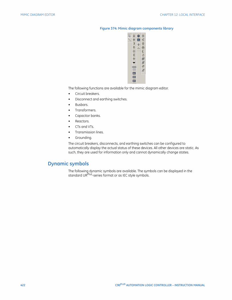
422 C90PLUS AUTOMATION LOGIC CONTROLLER – INSTRUCTION MANUAL
MIMIC DIAGRAM EDITOR CHAPTER 12: LOCAL INTERFACE
Figure 374: Mimic diagram components library
The following functions are available for the mimic diagram editor.
• Circuit breakers.
• Disconnect and earthing switches.
• Busbars.
• Transformers.
• Capacitor banks.
• Reactors.
• CTs and VTs.
• Transmission lines.
• Grounding.
The circuit breakers, disconnects, and earthing switches can be configured to automatically display the actual status of these devices. All other devices are static. As such, they are used for information only and cannot dynamically change states.
Dynamic symbolsThe following dynamic symbols are available. The symbols can be displayed in the standard URPlus-series format or as IEC style symbols.
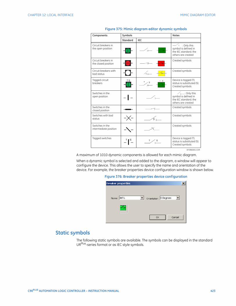
CHAPTER 12: LOCAL INTERFACE MIMIC DIAGRAM EDITOR
C90PLUS AUTOMATION LOGIC CONTROLLER – INSTRUCTION MANUAL 423
Figure 375: Mimic diagram editor dynamic symbols
A maximum of 1010 dynamic components is allowed for each mimic diagram.
When a dynamic symbol is selected and added to the diagram, a window will appear to configure the device. This allows the user to specify the name and orientation of the device. For example, the breaker properties device configuration window is shown below.
Figure 376: Breaker properties device configuration
Static symbolsThe following static symbols are available. The symbols can be displayed in the standard URPlus-series format or as IEC style symbols.
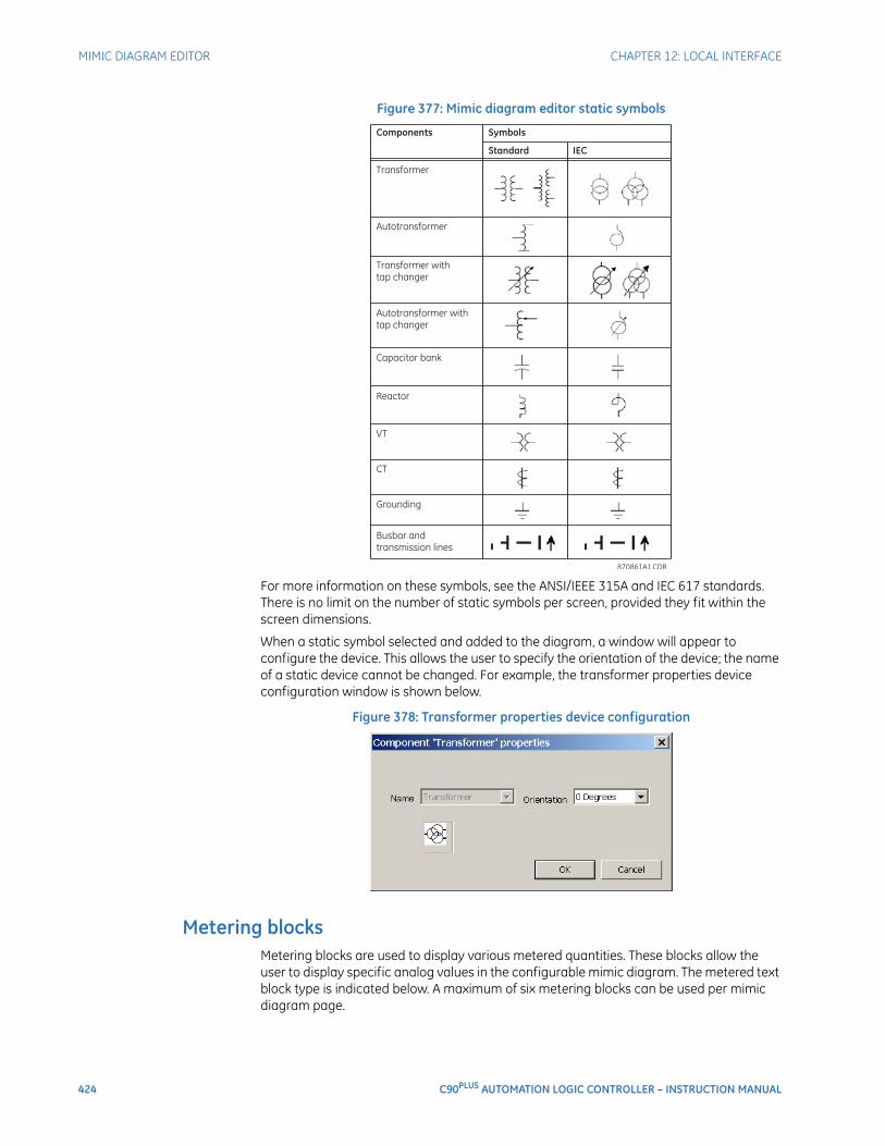
424 C90PLUS AUTOMATION LOGIC CONTROLLER – INSTRUCTION MANUAL
MIMIC DIAGRAM EDITOR CHAPTER 12: LOCAL INTERFACE
Figure 377: Mimic diagram editor static symbols
For more information on these symbols, see the ANSI/IEEE 315A and IEC 617 standards. There is no limit on the number of static symbols per screen, provided they fit within the screen dimensions.
When a static symbol selected and added to the diagram, a window will appear to configure the device. This allows the user to specify the orientation of the device; the name of a static device cannot be changed. For example, the transformer properties device configuration window is shown below.
Figure 378: Transformer properties device configuration
Metering blocksMetering blocks are used to display various metered quantities. These blocks allow the user to display specific analog values in the configurable mimic diagram. The metered text block type is indicated below. A maximum of six metering blocks can be used per mimic diagram page.
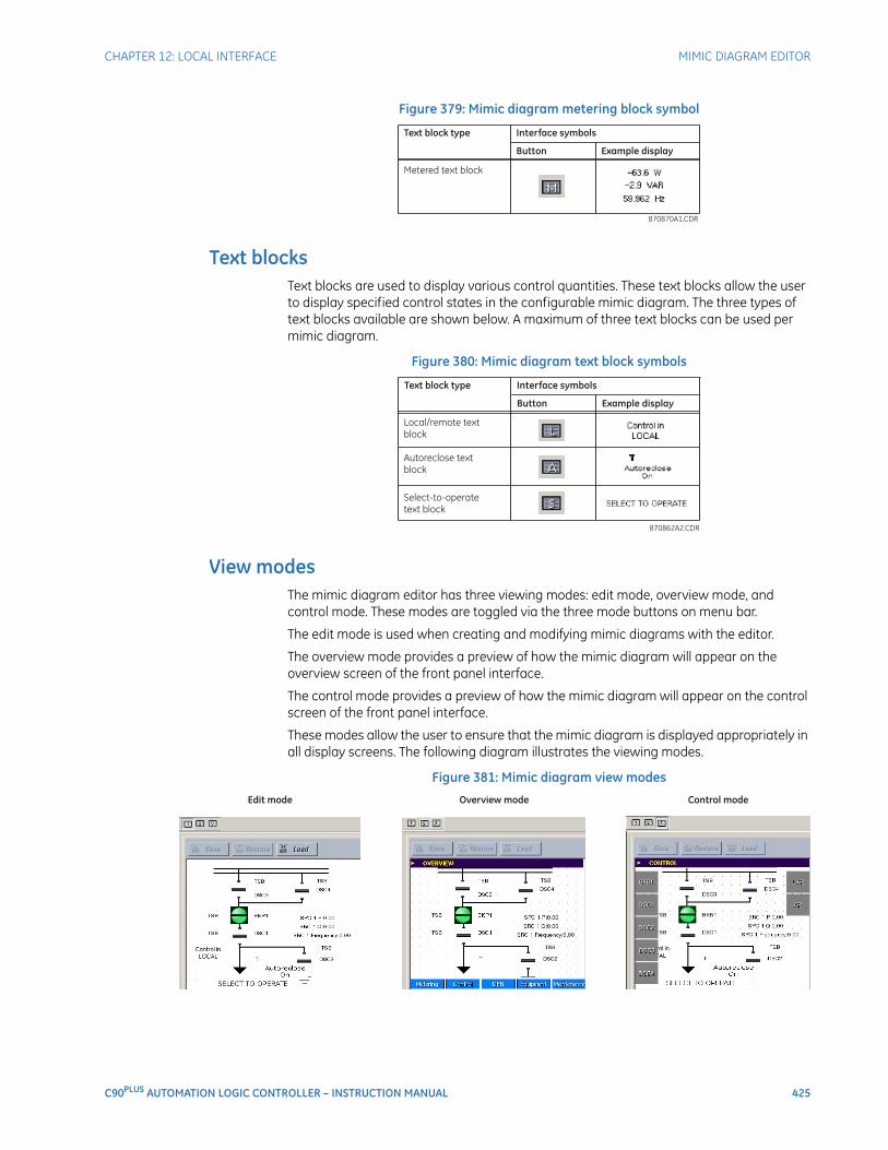
CHAPTER 12: LOCAL INTERFACE MIMIC DIAGRAM EDITOR
C90PLUS AUTOMATION LOGIC CONTROLLER – INSTRUCTION MANUAL 425
Figure 379: Mimic diagram metering block symbol
Text blocksText blocks are used to display various control quantities. These text blocks allow the user to display specified control states in the configurable mimic diagram. The three types of text blocks available are shown below. A maximum of three text blocks can be used per mimic diagram.
Figure 380: Mimic diagram text block symbols
View modesThe mimic diagram editor has three viewing modes: edit mode, overview mode, and control mode. These modes are toggled via the three mode buttons on menu bar.
The edit mode is used when creating and modifying mimic diagrams with the editor.
The overview mode provides a preview of how the mimic diagram will appear on the overview screen of the front panel interface.
The control mode provides a preview of how the mimic diagram will appear on the control screen of the front panel interface.
These modes allow the user to ensure that the mimic diagram is displayed appropriately in all display screens. The following diagram illustrates the viewing modes.
Figure 381: Mimic diagram view modes
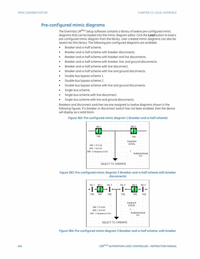
426 C90PLUS AUTOMATION LOGIC CONTROLLER – INSTRUCTION MANUAL
MIMIC DIAGRAM EDITOR CHAPTER 12: LOCAL INTERFACE
Pre-configured mimic diagramsThe EnerVista URPlus Setup software contains a library of twelve pre-configured mimic diagrams that can be loaded into the mimic diagram editor. Click the Load button to load a pre-configured mimic diagram from the library. User-created mimic diagrams can also be saved into this library. The following pre-configured diagrams are available.
• Breaker-and-a-half scheme.
• Breaker-and-a-half scheme with breaker disconnects.
• Breaker-and-a-half scheme with breaker and line disconnects.
• Breaker-and-a-half scheme with breaker, line, and ground disconnects.
• Breaker-and-a-half scheme with line disconnect.
• Breaker-and-a-half scheme with line and ground disconnects.
• Double-bus bypass scheme 1.
• Double-bus bypass scheme 2.
• Double-bus bypass scheme with line and ground disconnects.
• Single-bus scheme.
• Single-bus scheme with line disconnect.
• Single-bus scheme with line and ground disconnects.
Breakers and disconnect switches are pre-assigned to twelve diagrams shown in the following figures. If a breaker or disconnect switch has not been enabled, then the device will display as a solid block.
Figure 382: Pre-configured mimic diagram 1 (breaker-and-a-half scheme)
Figure 383: Pre-configured mimic diagram 2 (breaker-and-a-half scheme with breaker disconnects)
Figure 384: Pre-configured mimic diagram 3 (breaker-and-a-half scheme, with breaker
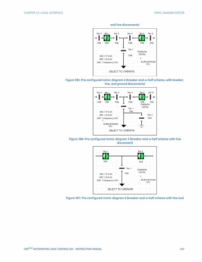
CHAPTER 12: LOCAL INTERFACE MIMIC DIAGRAM EDITOR
C90PLUS AUTOMATION LOGIC CONTROLLER – INSTRUCTION MANUAL 427
and line disconnects)
Figure 385: Pre-configured mimic diagram 4 (breaker-and-a-half scheme, with breaker, line, and ground disconnects)
Figure 386: Pre-configured mimic diagram 5 (breaker-and-a-half scheme with line disconnect)
Figure 387: Pre-configured mimic diagram 6 (breaker-and-a-half scheme with line and
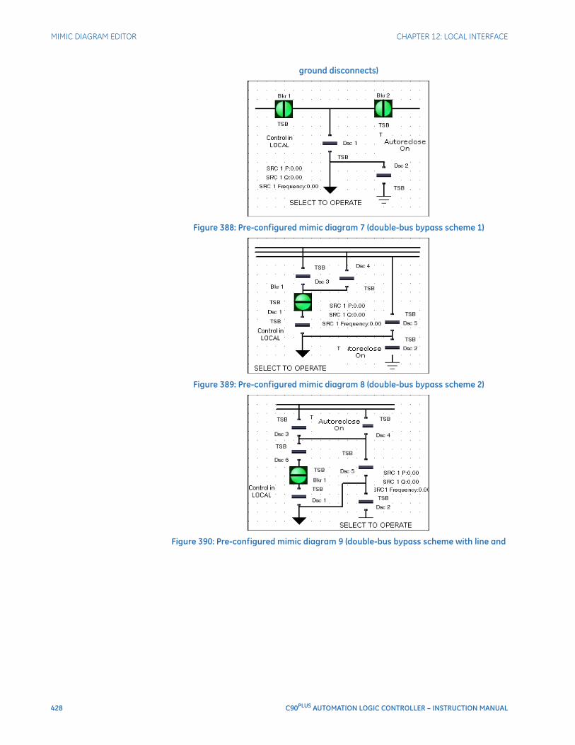
428 C90PLUS AUTOMATION LOGIC CONTROLLER – INSTRUCTION MANUAL
MIMIC DIAGRAM EDITOR CHAPTER 12: LOCAL INTERFACE
ground disconnects)
Figure 388: Pre-configured mimic diagram 7 (double-bus bypass scheme 1)
Figure 389: Pre-configured mimic diagram 8 (double-bus bypass scheme 2)
Figure 390: Pre-configured mimic diagram 9 (double-bus bypass scheme with line and
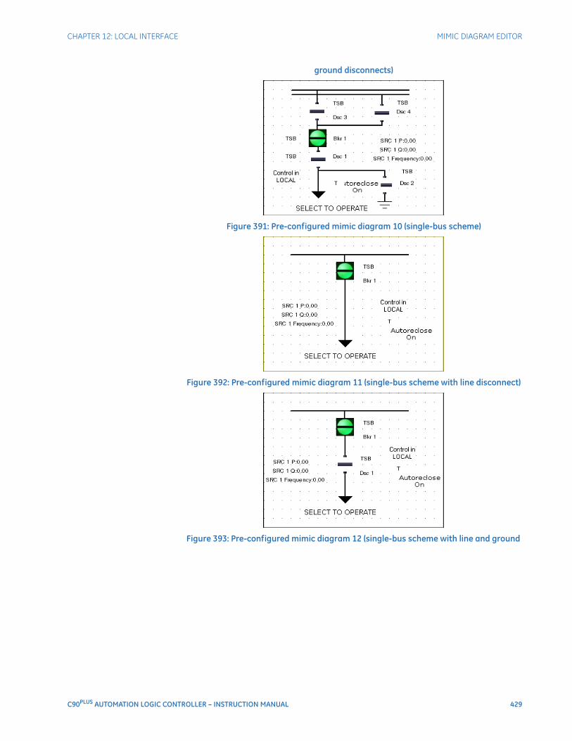
CHAPTER 12: LOCAL INTERFACE MIMIC DIAGRAM EDITOR
C90PLUS AUTOMATION LOGIC CONTROLLER – INSTRUCTION MANUAL 429
ground disconnects)
Figure 391: Pre-configured mimic diagram 10 (single-bus scheme)
Figure 392: Pre-configured mimic diagram 11 (single-bus scheme with line disconnect)
Figure 393: Pre-configured mimic diagram 12 (single-bus scheme with line and ground
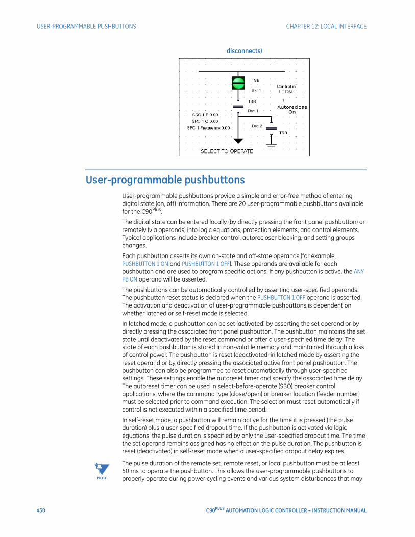
430 C90PLUS AUTOMATION LOGIC CONTROLLER – INSTRUCTION MANUAL
USER-PROGRAMMABLE PUSHBUTTONS CHAPTER 12: LOCAL INTERFACE
disconnects)
User-programmable pushbuttonsUser-programmable pushbuttons provide a simple and error-free method of entering digital state (on, off) information. There are 20 user-programmable pushbuttons available for the C90Plus.
The digital state can be entered locally (by directly pressing the front panel pushbutton) or remotely (via operands) into logic equations, protection elements, and control elements. Typical applications include breaker control, autorecloser blocking, and setting groups changes.
Each pushbutton asserts its own on-state and off-state operands (for example, PUSHBUTTON 1 ON and PUSHBUTTON 1 OFF). These operands are available for each pushbutton and are used to program specific actions. If any pushbutton is active, the ANY PB ON operand will be asserted.
The pushbuttons can be automatically controlled by asserting user-specified operands. The pushbutton reset status is declared when the PUSHBUTTON 1 OFF operand is asserted. The activation and deactivation of user-programmable pushbuttons is dependent on whether latched or self-reset mode is selected.
In latched mode, a pushbutton can be set (activated) by asserting the set operand or by directly pressing the associated front panel pushbutton. The pushbutton maintains the set state until deactivated by the reset command or after a user-specified time delay. The state of each pushbutton is stored in non-volatile memory and maintained through a loss of control power. The pushbutton is reset (deactivated) in latched mode by asserting the reset operand or by directly pressing the associated active front panel pushbutton. The pushbutton can also be programmed to reset automatically through user-specified settings. These settings enable the autoreset timer and specify the associated time delay. The autoreset timer can be used in select-before-operate (SBO) breaker control applications, where the command type (close/open) or breaker location (feeder number) must be selected prior to command execution. The selection must reset automatically if control is not executed within a specified time period.
In self-reset mode, a pushbutton will remain active for the time it is pressed (the pulse duration) plus a user-specified dropout time. If the pushbutton is activated via logic equations, the pulse duration is specified by only the user-specified dropout time. The time the set operand remains assigned has no effect on the pulse duration. The pushbutton is reset (deactivated) in self-reset mode when a user-specified dropout delay expires.
NOTE
NOTE: The pulse duration of the remote set, remote reset, or local pushbutton must be at least 50 ms to operate the pushbutton. This allows the user-programmable pushbuttons to properly operate during power cycling events and various system disturbances that may
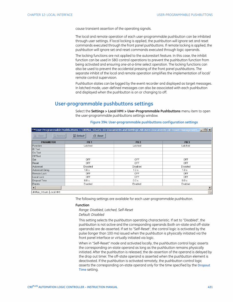
CHAPTER 12: LOCAL INTERFACE USER-PROGRAMMABLE PUSHBUTTONS
C90PLUS AUTOMATION LOGIC CONTROLLER – INSTRUCTION MANUAL 431
cause transient assertion of the operating signals.
The local and remote operation of each user-programmable pushbutton can be inhibited through user settings. If local locking is applied, the pushbutton will ignore set and reset commands executed through the front panel pushbuttons. If remote locking is applied, the pushbutton will ignore set and reset commands executed through logic operands.
The locking functions are not applied to the autorestart feature. In this case, the inhibit function can be used in SBO control operations to prevent the pushbutton function from being activated and ensuring one-at-a-time select operation. The locking functions can also be used to prevent the accidental pressing of the front panel pushbuttons. The separate inhibit of the local and remote operation simplifies the implementation of local/remote control supervision.
Pushbutton states can be logged by the event recorder and displayed as target messages. In latched mode, user-defined messages can also be associated with each pushbutton and displayed when the pushbutton is on or changing to off.
User-programmable pushbuttons settingsSelect the Settings > Local HMI > User-Programmable Pushbuttons menu item to open the user-programmable pushbuttons settings window.
Figure 394: User-programmable pushbuttons configuration settings
The following settings are available for each user-programmable pushbutton.
FunctionRange: Disabled, Latched, Self-ResetDefault: Disabled
This setting selects the pushbutton operating characteristic. If set to “Disabled”, the pushbutton is not active and the corresponding operands (both on-state and off-state operands) are de-asserted. If set to “Self-Reset”, the control logic is activated by the pulse (longer than 100 ms) issued when the pushbutton is physically initiated via the front panel interface or virtually initiated via logic.
When in “Self-Reset” mode and activated locally, the pushbutton control logic asserts the corresponding on-state operand as long as the pushbutton remains physically initiated. After the pushbutton is released, the de-assertion of the operand is delayed by the drop out timer. The off-state operand is asserted when the pushbutton element is deactivated. If the pushbutton is activated remotely, the pushbutton control logic asserts the corresponding on-state operand only for the time specified by the Dropout Time setting.

432 C90PLUS AUTOMATION LOGIC CONTROLLER – INSTRUCTION MANUAL
USER-PROGRAMMABLE PUSHBUTTONS CHAPTER 12: LOCAL INTERFACE
If set to “Latched”, the pushbutton control logic alternates the state of the corresponding operand between the on-state and off-state on each button press or by virtually activating the pushbutton (assigning set and reset operands). In latched mode, the operand states are stored in non-volatile memory. Should supply power be lost, the correct state of the pushbutton is retained upon subsequent power-up.
ID TextRange: up to 20 alphanumeric charactersDefault: empty
This setting specifies the name (ID) for the user-programmable pushbutton.
On TextRange: up to 20 alphanumeric charactersDefault: empty
This setting specifies the text to display when the pushbutton is in the on position.
Off TextRange: up to 20 alphanumeric charactersDefault: empty
This setting specifies the text to display when the pushbutton is in the off position. This message is not displayed in self-reset mode as the pushbutton operand status is implied to be off upon its release.
SetRange: any FlexLogic™ operand or shared operandDefault: OFF
When the operand assigned to this setting is asserted, the pushbutton is operated and the PUSHBUTTON 1 ON operand is asserted. The duration of the incoming set signal must be at least 100 ms.
ResetRange: any FlexLogic™ operand or shared operandDefault: OFF
When the operand assigned to this setting is asserted, the pushbutton is reset and the PUSHBUTTON 1 OFF operand is asserted. This setting is applicable only if the pushbutton is in latched mode. The duration of the incoming set signal must be at least 100 ms.
AutoresetRange: Disabled, EnabledDefault: Disabled
This setting enables the user-programmable pushbutton autoreset feature. This setting is applicable only if the pushbutton is in latched mode.
Autoreset DelayRange: 0.2 to 600.0 seconds in steps of 0.1Default: 1.0 seconds
This setting specifies the time delay for automatic reset of the pushbutton when in the latched mode.
Remote LockRange: any FlexLogic™ operand or shared operandDefault: OFF
When the operand assigned to this setting is asserted, pushbutton operation from operands assigned to the Set or Reset settings is inhibited.
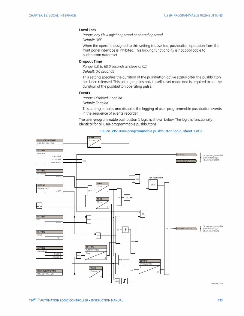
CHAPTER 12: LOCAL INTERFACE USER-PROGRAMMABLE PUSHBUTTONS
C90PLUS AUTOMATION LOGIC CONTROLLER – INSTRUCTION MANUAL 433
Local LockRange: any FlexLogic™ operand or shared operandDefault: OFF
When the operand assigned to this setting is asserted, pushbutton operation from the front panel interface is inhibited. This locking functionality is not applicable to pushbutton autoreset.
Dropout TimeRange: 0.0 to 60.0 seconds in steps of 0.1Default: 0.0 seconds
This setting specifies the duration of the pushbutton active status after the pushbutton has been released. This setting applies only to self-reset mode and is required to set the duration of the pushbutton operating pulse.
EventsRange: Disabled, EnabledDefault: Enabled
This setting enables and disables the logging of user-programmable pushbutton events in the sequence of events recorder.
The user-programmable pushbutton 1 logic is shown below. The logic is functionally identical for all user-programmable pushbuttons.
Figure 395: User-programmable pushbutton logic, sheet 1 of 2
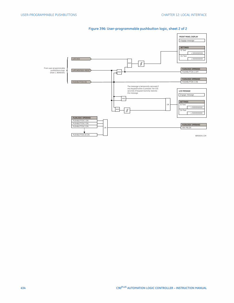
434 C90PLUS AUTOMATION LOGIC CONTROLLER – INSTRUCTION MANUAL
USER-PROGRAMMABLE PUSHBUTTONS CHAPTER 12: LOCAL INTERFACE
Figure 396: User-programmable pushbutton logic, sheet 2 of 2
C90PLUS AUTOMATION LOGIC CONTROLLER – INSTRUCTION MANUAL 435
C90Plus Automation Logic Controller
Chapter 13: Security
Security
This section describes how to program the C90Plus security features.
Password securityIt is recommended that passwords be programmed for each security level and assigned to specific personnel. There are two user password security access levels: command and setting.
The command access level restricts the user from making any settings changes, but allows the user to perform the following operations.
• Operate breakers via the front panel interface.
• Change the state of virtual inputs.
• Clear event records.
• Clear oscillography records.
• Clear fault reports.
• Change the system date and time.
• Clear energy records.
• Operate control pushbuttons.
The setting access level allows the user to make any changes to any of the setting values and operate in test mode.
The command and setting passwords are not programmed when the device is shipped from the factory. When a command or setting password is set to null, the password security feature is disabled.
The C90Plus supports password entry from a local or remote connection.
Local access is defined as any access to settings or commands via the faceplate interface. This includes both keypad entry and the faceplate serial USB connection. Remote access is defined as any access to settings or commands via any rear Ethernet port. Any changes to the local or remote passwords enables this functionality.
The RS485 port can be configured as a either a local or remote connection through the serial port Connection setting.
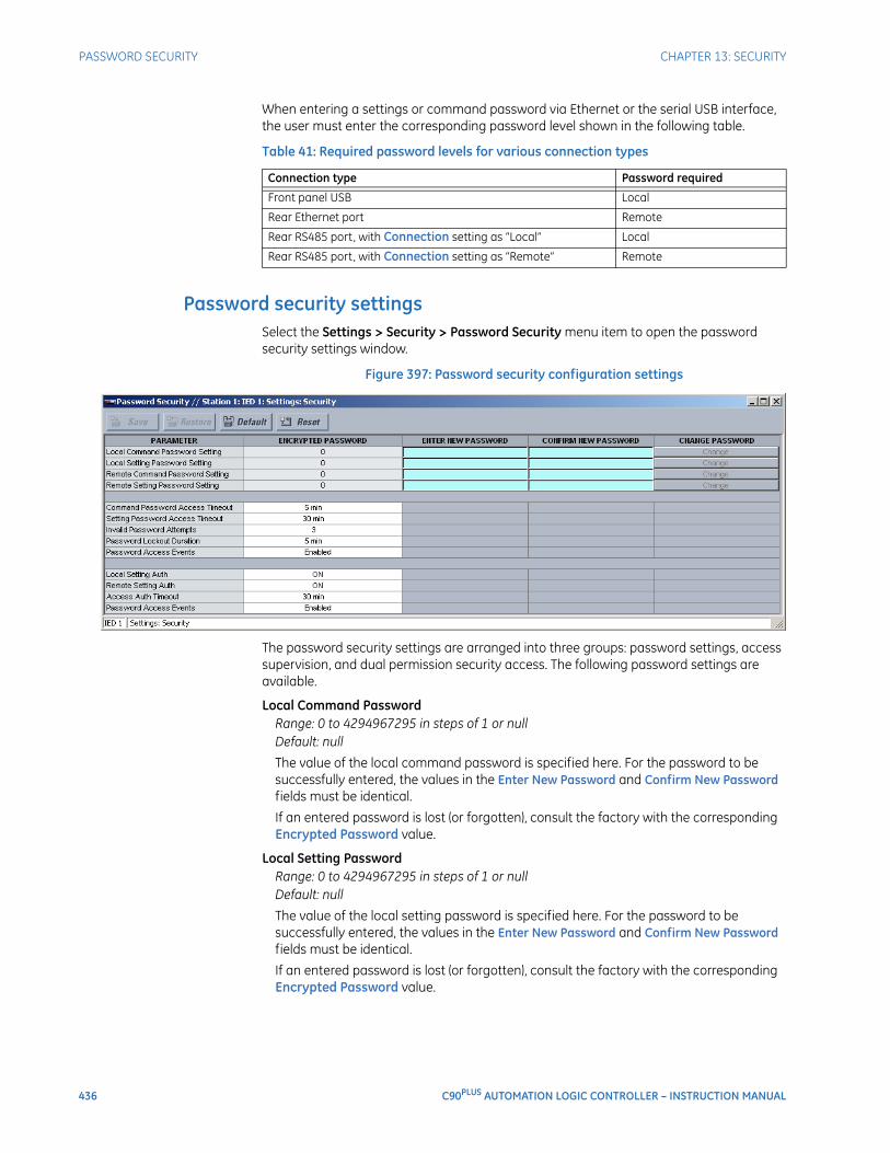
436 C90PLUS AUTOMATION LOGIC CONTROLLER – INSTRUCTION MANUAL
PASSWORD SECURITY CHAPTER 13: SECURITY
When entering a settings or command password via Ethernet or the serial USB interface, the user must enter the corresponding password level shown in the following table.
Table 41: Required password levels for various connection types
Password security settingsSelect the Settings > Security > Password Security menu item to open the password security settings window.
Figure 397: Password security configuration settings
The password security settings are arranged into three groups: password settings, access supervision, and dual permission security access. The following password settings are available.
Local Command PasswordRange: 0 to 4294967295 in steps of 1 or nullDefault: null
The value of the local command password is specified here. For the password to be successfully entered, the values in the Enter New Password and Confirm New Password fields must be identical.
If an entered password is lost (or forgotten), consult the factory with the corresponding Encrypted Password value.
Local Setting PasswordRange: 0 to 4294967295 in steps of 1 or nullDefault: null
The value of the local setting password is specified here. For the password to be successfully entered, the values in the Enter New Password and Confirm New Password fields must be identical.
If an entered password is lost (or forgotten), consult the factory with the corresponding Encrypted Password value.
Connection type Password required
Front panel USB Local
Rear Ethernet port Remote
Rear RS485 port, with Connection setting as “Local” Local
Rear RS485 port, with Connection setting as “Remote” Remote

CHAPTER 13: SECURITY PASSWORD SECURITY
C90PLUS AUTOMATION LOGIC CONTROLLER – INSTRUCTION MANUAL 437
Remote Command PasswordRange: 0 to 4294967295 in steps of 1 or nullDefault: null
The value of the remote command password is specified here. For the password to be successfully entered, the values in the Enter New Password and Confirm New Password fields must be identical.
If an entered password is lost (or forgotten), consult the factory with the corresponding Encrypted Password value.
Remote Setting PasswordRange: 0 to 4294967295 in steps of 1 or nullDefault: null
The value of the remote setting password is specified here. For the password to be successfully entered, the values in the Enter New Password and Confirm New Password fields must be identical.
If an entered password is lost (or forgotten), consult the factory with the corresponding Encrypted Password value.
The access supervision settings allow the user to specify the length of inactivity required before returning to the restricted access level. The following access supervision settings are available.
Command Password Access TimeoutRange: 5 to 480 minutes in steps of 1Default: 5 minutes
This setting specifies the length of inactivity (no local or remote access) required to return to restricted access from the command password level.
Setting Password Access TimeoutRange: 5 to 480 minutes in steps of 1Default: 30 minutes
This setting specifies the length of inactivity (no local or remote access) required to return to restricted access from the setting password level.
Invalid Password AttemptsRange: 2 to 5 in steps of 1Default: 3
This setting specifies the number of times an incorrect password can be entered within a three-minute time span before lockout occurs and applies to both the setting and command passwords.
When lockout occurs for the command password level, the ACCESS LOC CMND DENY and ACCESS REM CMND DENY communication operands are set to “On”. These operands are returned to the “Off” state upon expiration of the lockout. Likewise, when lockout occurs for the setting password level, the ACCESS LOC SETG DENY and ACCESS REM SETG DENY communication operands are set to “On”. These operands are also returned to the “Off” state upon expiration of the lockout.
Password Lockout DurationRange: 5 to 60 minutes in steps of 1Default: 5 minutes
This setting specifies the time that the C90Plus will lockout command password access after the number of invalid password entries specified by the Invalid Password Attempts setting has occurred.
438 C90PLUS AUTOMATION LOGIC CONTROLLER – INSTRUCTION MANUAL
PASSWORD SECURITY CHAPTER 13: SECURITY
Password Access EventsRange: Enabled, DisabledDefault: Disabled
This setting enables and disables the logging of password access supervision events in the sequence of events recorder.
The dual permission security access feature provides a mechanism for customers to prevent unauthorized or unintended upload of settings to a device through the local or remote interfaces. The following dual permission security access settings are available.
Local Setting AuthorizationRange: selected operands (see description below)Default: ON
This setting is used for local (front panel USB and RS485 interface) setting access supervision. Valid operand values are either “ON” (default) or any physical contact input value.
If this setting is “ON”, then local setting access functions as normal; that is, a local setting password is required. If this setting value is any contact input operand, then the operand must be asserted (set as on) prior to providing the local setting password to gain setting access.
Remote Setting AuthorizationRange: any communications operand or shared operandDefault: ON
This setting is used for remote (Ethernet and RS485) setting access supervision.
If this setting is “ON” (the default setting), then remote setting access functions as normal; that is, a remote password is required). If this setting is “OFF”, then remote setting access is blocked even if the correct remote setting password is provided. If this setting is any other operand, then the operand must be asserted (set as on) prior to providing the remote setting password to gain setting access.
Access Authorization TimeoutRange: 5 to 480 minutes in steps of 1Default: 30 minutes
This setting specifies the timeout delay for setting access. This setting is applicable when the Local Setting Authorization or Remote Setting Authorization settings are programmed to any operand except “ON” or “OFF”. The states of any selected operands are continuously monitored for an off-to-on transition. When this occurs, setting access is permitted and the timer programmed with this setting value is started. When this timer expires, setting access is immediately denied. If access is permitted and an off-to-on transition of the selected operand is detected, the timeout is restarted. The status of this timer is updated every five seconds.
Password Access EventsRange: Enabled, DisabledDefault: Disabled
This setting enables and disables the logging of dual permission security access events in the sequence of events recorder.
Password security operationIn the event that an incorrect command or setting password has been entered three times within a three-minute time span, the ACCESS DENIED operand will be asserted and the C90Plus will not allow setting or command access for the next ten minutes. The operand will be de-asserted after the expiration of the ten-minute timeout.
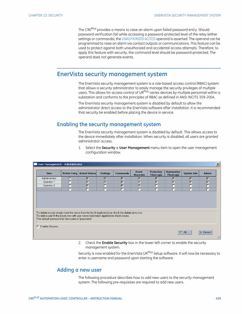
CHAPTER 13: SECURITY ENERVISTA SECURITY MANAGEMENT SYSTEM
C90PLUS AUTOMATION LOGIC CONTROLLER – INSTRUCTION MANUAL 439
The C90Plus provides a means to raise an alarm upon failed password entry. Should password verification fail while accessing a password-protected level of the relay (either settings or commands), the UNAUTHORIZED ACCESS operand is asserted. The operand can be programmed to raise an alarm via contact outputs or communications. This feature can be used to protect against both unauthorized and accidental access attempts. Therefore, to apply this feature with security, the command level should be password-protected. The operand does not generate events.
EnerVista security management systemThe EnerVista security management system is a role-based access control (RBAC) system that allows a security administrator to easily manage the security privileges of multiple users. This allows for access control of URPlus-series devices by multiple personnel within a substation and conforms to the principles of RBAC as defined in ANSI INCITS 359-2004.
The EnerVista security management system is disabled by default to allow the administrator direct access to the EnerVista software after installation. It is recommended that security be enabled before placing the device in service.
Enabling the security management systemThe EnerVista security management system is disabled by default. This allows access to the device immediately after installation. When security is disabled, all users are granted administrator access.
1. Select the Security > User Management menu item to open the user management configuration window.
2. Check the Enable Security box in the lower-left corner to enable the security management system.
Security is now enabled for the EnerVista URPlus Setup software. It will now be necessary to enter a username and password upon starting the software.
Adding a new userThe following procedure describes how to add new users to the security management system. The following pre-requisites are required to add new users.
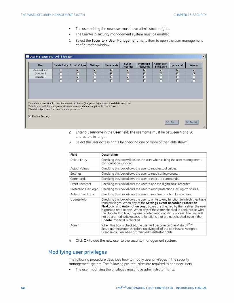
440 C90PLUS AUTOMATION LOGIC CONTROLLER – INSTRUCTION MANUAL
ENERVISTA SECURITY MANAGEMENT SYSTEM CHAPTER 13: SECURITY
• The user adding the new user must have administrator rights.
• The EnerVista security management system must be enabled.
1. Select the Security > User Management menu item to open the user management configuration window.
2. Enter a username in the User field. The username must be between 4 and 20 characters in length.
3. Select the user access rights by checking one or more of the fields shown.
4. Click OK to add the new user to the security management system.
Modifying user privilegesThe following procedure describes how to modify user privileges in the security management system. The following pre-requisites are required to add new users.
• The user modifying the privileges must have administrator rights.
Field Description
Delete Entry Checking this box will delete the user when exiting the user management configuration window.
Actual Values Checking this box allows the user to read actual values.
Settings Checking this box allows the user to read setting values.
Commands Checking this box allows the user to execute commands.
Event Recorder Checking this box allows the user to use the digital fault recorder.
Protection FlexLogic Checking this box allows the user to read protection FlexLogic™ values.
Automation Logic Checking this box allows the user to read automation logic values.
Update Info Checking this box allows the user to write to any function to which they have read privileges. When any of the Settings, Event Recorder, Protection FlexLogic, and Automation Logic boxes are checked by themselves, the user is granted read access. When any of these are checked in conjunction with the Update Info box, they are granted read and write access. The user will not be granted write access to functions that are not checked, even if the Update Info field is checked.
Admin When this box is checked, the user will become an EnerVista URPlus Setup administrator, therefore receiving all of the administrative rights. Exercise caution when granting administrator rights.
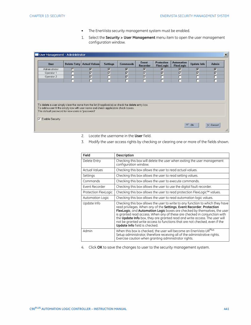
CHAPTER 13: SECURITY ENERVISTA SECURITY MANAGEMENT SYSTEM
C90PLUS AUTOMATION LOGIC CONTROLLER – INSTRUCTION MANUAL 441
• The EnerVista security management system must be enabled.
1. Select the Security > User Management menu item to open the user management configuration window.
2. Locate the username in the User field.
3. Modify the user access rights by checking or clearing one or more of the fields shown.
4. Click OK to save the changes to user to the security management system.
Field Description
Delete Entry Checking this box will delete the user when exiting the user management configuration window.
Actual Values Checking this box allows the user to read actual values.
Settings Checking this box allows the user to read setting values.
Commands Checking this box allows the user to execute commands.
Event Recorder Checking this box allows the user to use the digital fault recorder.
Protection FlexLogic Checking this box allows the user to read protection FlexLogic™ values.
Automation Logic Checking this box allows the user to read automation logic values.
Update Info Checking this box allows the user to write to any function to which they have read privileges. When any of the Settings, Event Recorder, Protection FlexLogic, and Automation Logic boxes are checked by themselves, the user is granted read access. When any of these are checked in conjunction with the Update Info box, they are granted read and write access. The user will not be granted write access to functions that are not checked, even if the Update Info field is checked.
Admin When this box is checked, the user will become an EnerVista URPlus Setup administrator, therefore receiving all of the administrative rights. Exercise caution when granting administrator rights.

442 C90PLUS AUTOMATION LOGIC CONTROLLER – INSTRUCTION MANUAL
ENERVISTA SECURITY MANAGEMENT SYSTEM CHAPTER 13: SECURITY
C90PLUS AUTOMATION LOGIC CONTROLLER – INSTRUCTION MANUAL 443
C90Plus Automation Logic Controller
Chapter 14: Testing
Testing
This section describes the C90Plus testing features.
Test modeThe C90Plus provides test settings to verify that functionality using simulated conditions for contact inputs and outputs. To initiate the test mode, the Test Mode Function setting must be “Enabled” and the operand assigned to the Test Mode Initiate setting must be set to logic 1.
In particular, the test mode is initiated as follows.
• To initiate test mode through the C90Plus settings, set the Test Mode Initiate to “ON”. The test mode starts when the Test Mode Function setting is changed from “Disabled” to “Enabled”.
• To initiate test mode through a user-programmable condition, such as FlexLogic™ operand, set the Test Mode Function setting to “Enabled” and the Test Mode Initiate to the desired operand. The test mode starts when the selected operand assumes a logic 1 state.
When in the test mode, the C90Plus remains fully operational, allowing for various testing procedures. The only difference between the normal operation and the test mode is the behavior of the input and output contacts. The former can be forced to report as open or closed or remain fully operational; the latter can be forced to open, close, freeze, or remain fully operational. The response of the digital input and output contacts to the test mode is programmed individually for each input and output using the force contact inputs and force contact outputs test functions described in the following sections.
Force contact inputsThe force contact inputs feature provides a method of performing checks on the function of all contact inputs. Once enabled, the C90Plus is placed into test mode, allowing this feature to override the normal function of contact inputs. All contact input operations return to normal when all settings for this feature are disabled.
Select the Settings > Testing > Force Contact Inputs menu item to open the force contact inputs configuration window.
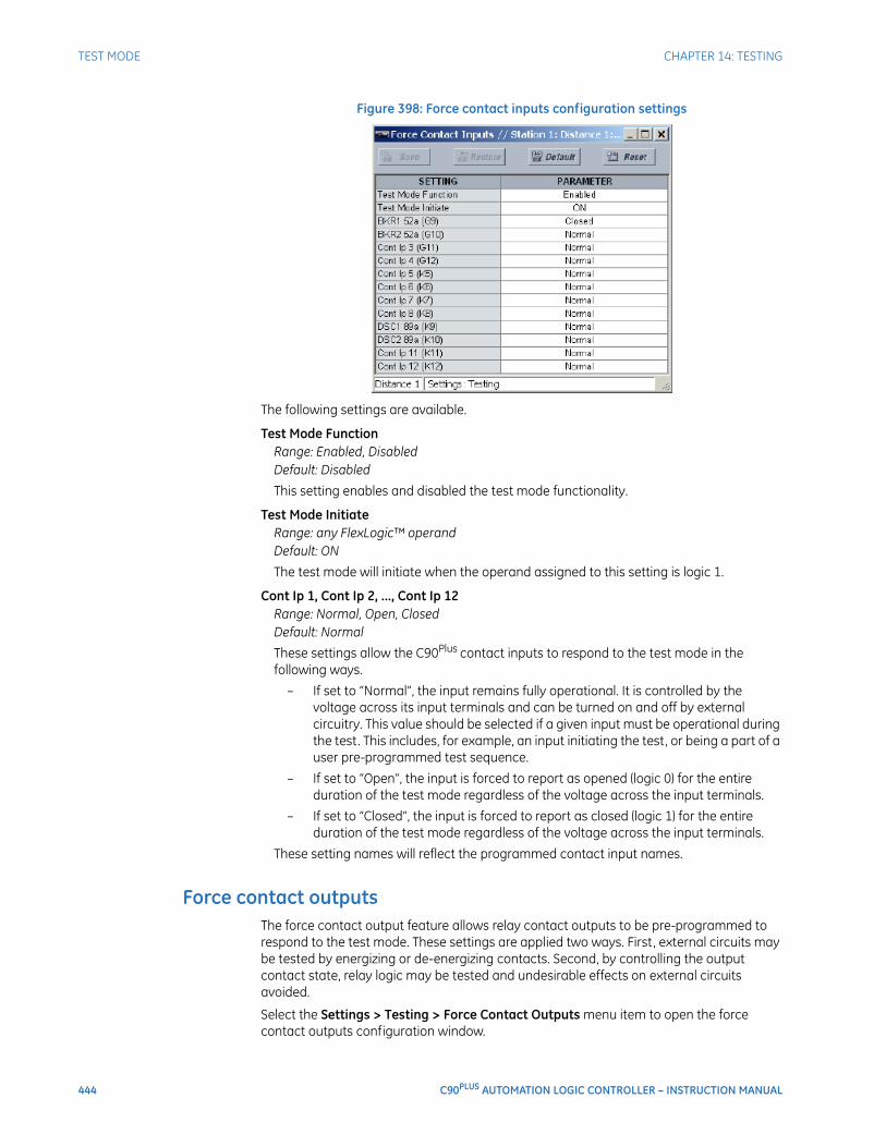
444 C90PLUS AUTOMATION LOGIC CONTROLLER – INSTRUCTION MANUAL
TEST MODE CHAPTER 14: TESTING
Figure 398: Force contact inputs configuration settings
The following settings are available.
Test Mode FunctionRange: Enabled, DisabledDefault: Disabled
This setting enables and disabled the test mode functionality.
Test Mode InitiateRange: any FlexLogic™ operandDefault: ON
The test mode will initiate when the operand assigned to this setting is logic 1.
Cont Ip 1, Cont Ip 2, ..., Cont Ip 12Range: Normal, Open, ClosedDefault: Normal
These settings allow the C90Plus contact inputs to respond to the test mode in the following ways.
– If set to “Normal”, the input remains fully operational. It is controlled by the voltage across its input terminals and can be turned on and off by external circuitry. This value should be selected if a given input must be operational during the test. This includes, for example, an input initiating the test, or being a part of a user pre-programmed test sequence.
– If set to “Open”, the input is forced to report as opened (logic 0) for the entire duration of the test mode regardless of the voltage across the input terminals.
– If set to “Closed”, the input is forced to report as closed (logic 1) for the entire duration of the test mode regardless of the voltage across the input terminals.
These setting names will reflect the programmed contact input names.
Force contact outputsThe force contact output feature allows relay contact outputs to be pre-programmed to respond to the test mode. These settings are applied two ways. First, external circuits may be tested by energizing or de-energizing contacts. Second, by controlling the output contact state, relay logic may be tested and undesirable effects on external circuits avoided.
Select the Settings > Testing > Force Contact Outputs menu item to open the force contact outputs configuration window.
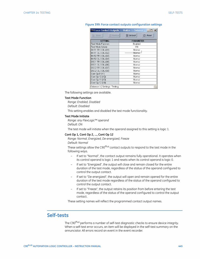
CHAPTER 14: TESTING SELF-TESTS
C90PLUS AUTOMATION LOGIC CONTROLLER – INSTRUCTION MANUAL 445
Figure 399: Force contact outputs configuration settings
The following settings are available.
Test Mode FunctionRange: Enabled, DisabledDefault: Disabled
This setting enables and disabled the test mode functionality.
Test Mode InitiateRange: any FlexLogic™ operandDefault: ON
The test mode will initiate when the operand assigned to this setting is logic 1.
Cont Op 1, Cont Op 2, ..., Cont Op 12Range: Normal, Energized, De-energized, FreezeDefault: Normal
These settings allow the C90Plus contact outputs to respond to the test mode in the following ways.
– If set to “Normal”, the contact output remains fully operational. It operates when its control operand is logic 1 and resets when its control operand is logic 0.
– If set to “Energized”, the output will close and remain closed for the entire duration of the test mode, regardless of the status of the operand configured to control the output contact.
– If set to “De-energized”, the output will open and remain opened for the entire duration of the test mode regardless of the status of the operand configured to control the output contact.
– If set to “Freeze”, the output retains its position from before entering the test mode, regardless of the status of the operand configured to control the output contact.
These setting names will reflect the programmed contact output names.
Self-testsThe C90Plus performs a number of self-test diagnostic checks to ensure device integrity. When a self-test error occurs, an item will be displayed in the self-test summary on the annunciator. All errors record an event in the event recorder.
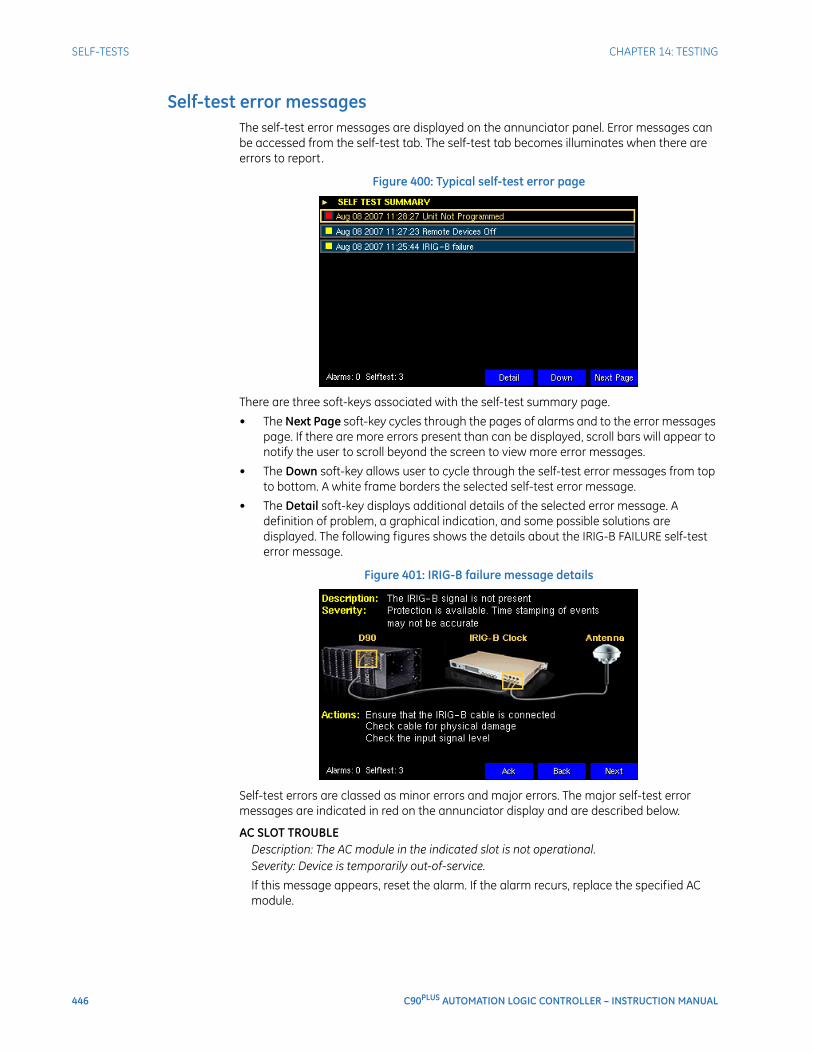
446 C90PLUS AUTOMATION LOGIC CONTROLLER – INSTRUCTION MANUAL
SELF-TESTS CHAPTER 14: TESTING
Self-test error messagesThe self-test error messages are displayed on the annunciator panel. Error messages can be accessed from the self-test tab. The self-test tab becomes illuminates when there are errors to report.
Figure 400: Typical self-test error page
There are three soft-keys associated with the self-test summary page.
• The Next Page soft-key cycles through the pages of alarms and to the error messages page. If there are more errors present than can be displayed, scroll bars will appear to notify the user to scroll beyond the screen to view more error messages.
• The Down soft-key allows user to cycle through the self-test error messages from top to bottom. A white frame borders the selected self-test error message.
• The Detail soft-key displays additional details of the selected error message. A definition of problem, a graphical indication, and some possible solutions are displayed. The following figures shows the details about the IRIG-B FAILURE self-test error message.
Figure 401: IRIG-B failure message details
Self-test errors are classed as minor errors and major errors. The major self-test error messages are indicated in red on the annunciator display and are described below.
AC SLOT TROUBLEDescription: The AC module in the indicated slot is not operational.Severity: Device is temporarily out-of-service.
If this message appears, reset the alarm. If the alarm recurs, replace the specified AC module.
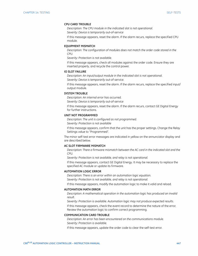
CHAPTER 14: TESTING SELF-TESTS
C90PLUS AUTOMATION LOGIC CONTROLLER – INSTRUCTION MANUAL 447
CPU CARD TROUBLEDescription: The CPU module in the indicated slot is not operational.Severity: Device is temporarily out-of-service
If this message appears, reset the alarm. If the alarm recurs, replace the specified CPU module.
EQUIPMENT MISMATCHDescription: The configuration of modules does not match the order code stored in the CPU.Severity: Protection is not available.
If this message appears, check all modules against the order code. Ensure they are inserted properly, and recycle the control power.
IO SLOT FAILUREDescription: An input/output module in the indicated slot is not operational.Severity: Device is temporarily out-of-service.
If this message appears, reset the alarm. If the alarm recurs, replace the specified input/output module.
SYSTEM TROUBLEDescription: An internal error has occurred.Severity: Device is temporarily out-of-service
If this message appears, reset the alarm. If the alarm recurs, contact GE Digital Energy for further instructions.
UNIT NOT PROGRAMMEDDescription: The unit is configured as not programmed.Severity: Protection is not available
If this message appears, confirm that the unit has the proper settings. Change the Relay Settings value to “Programmed”.
The minor self-test error messages are indicated in yellow on the annunciator display and are described below.
AC SLOT FIRMWARE MISMATCHDescription: There a firmware mismatch between the AC card in the indicated slot and the CPU.Severity: Protection is not available, and relay is not operational.
If this message appears, contact GE Digital Energy. It may be necessary to replace the specified AC module or update its firmware.
AUTOMATION LOGIC ERRORDescription: There is an error within an automation logic equation.Severity: Protection is not available, and relay is not operational.
If this message appears, modify the automation logic to make it valid and reload.
AUTOMATION MATH ERRORDescription: A mathematical operation in the automation logic has produced an invalid result.Severity: Protection is available. Automation logic may not produce expected results.
If this message appears, check the event record to determine the nature of the error. Review the automation logic to confirm correct programming.
COMMUNICATION CARD TROUBLEDescription: An error has been encountered on the communications module.Severity: Protection is available.
If this message appears, update the order code to clear the self-test error.
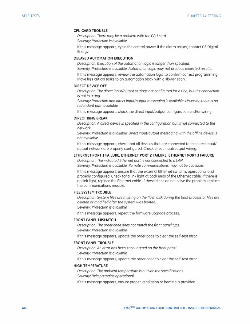
448 C90PLUS AUTOMATION LOGIC CONTROLLER – INSTRUCTION MANUAL
SELF-TESTS CHAPTER 14: TESTING
CPU CARD TROUBLEDescription: There may be a problem with the CPU card.Severity: Protection is available.
If this message appears, cycle the control power If the alarm recurs, contact GE Digital Energy.
DELAYED AUTOMATION EXECUTIONDescription: Execution of the automation logic is longer than specified.Severity: Protection is available. Automation logic may not produce expected results.
If this message appears, review the automation logic to confirm correct programming. Move less critical tasks to an automation block with a slower scan.
DIRECT DEVICE OFFDescription: The direct input/output settings are configured for a ring, but the connection is not in a ring.Severity: Protection and direct input/output messaging is available. However, there is no redundant path available.
If this message appears, check the direct input/output configuration and/or wiring.
DIRECT RING BREAKDescription: A direct device is specified in the configuration but is not connected to the network.Severity: Protection is available. Direct input/output messaging with the offline device is not available.
If this message appears, check that all devices that are connected to the direct input/output network are properly configured. Check direct input/output wiring.
ETHERNET PORT 1 FAILURE, ETHERNET PORT 2 FAILURE, ETHERNET PORT 3 FAILUREDescription: The indicated Ethernet port is not connected to a LAN.Severity: Protection is available. Remote communications may not be available.
If this message appears, ensure that the external Ethernet switch is operational and properly configured. Check for a link light at both ends of the Ethernet cable. If there is no link light, replace the Ethernet cable. If these steps do not solve the problem, replace the communications module.
FILE SYSTEM TROUBLEDescription: System files are missing on the flash disk during the boot process or files are deleted or modified after the system was booted.Severity: Protection is available.
If this message appears, repeat the firmware upgrade process.
FRONT PANEL MISMATCHDescription: The order code does not match the front panel type.Severity: Protection is available.
If this message appears, update the order code to clear the self-test error.
FRONT PANEL TROUBLEDescription: An error has been encountered on the front panel.Severity: Protection is available.
If this message appears, update the order code to clear the self-test error.
HIGH TEMPERATUREDescription: The ambient temperature is outside the specifications.Severity: Relay remains operational.
If this message appears, ensure proper ventilation or heating is provided.
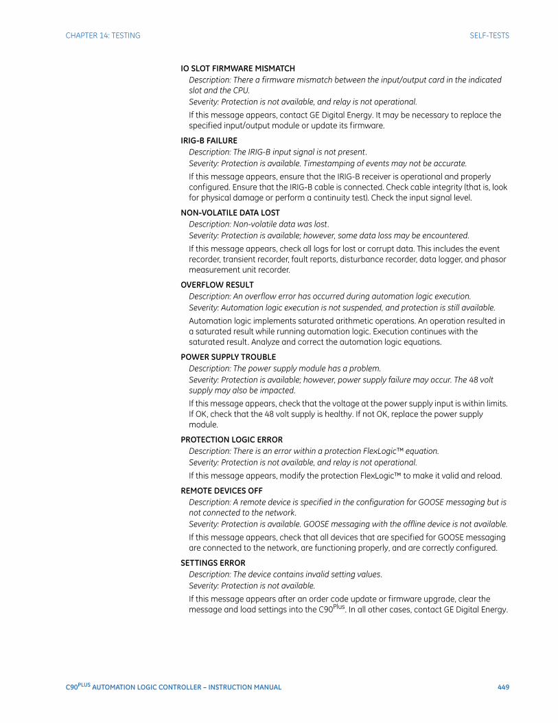
CHAPTER 14: TESTING SELF-TESTS
C90PLUS AUTOMATION LOGIC CONTROLLER – INSTRUCTION MANUAL 449
IO SLOT FIRMWARE MISMATCHDescription: There a firmware mismatch between the input/output card in the indicated slot and the CPU.Severity: Protection is not available, and relay is not operational.
If this message appears, contact GE Digital Energy. It may be necessary to replace the specified input/output module or update its firmware.
IRIG-B FAILUREDescription: The IRIG-B input signal is not present.Severity: Protection is available. Timestamping of events may not be accurate.
If this message appears, ensure that the IRIG-B receiver is operational and properly configured. Ensure that the IRIG-B cable is connected. Check cable integrity (that is, look for physical damage or perform a continuity test). Check the input signal level.
NON-VOLATILE DATA LOSTDescription: Non-volatile data was lost.Severity: Protection is available; however, some data loss may be encountered.
If this message appears, check all logs for lost or corrupt data. This includes the event recorder, transient recorder, fault reports, disturbance recorder, data logger, and phasor measurement unit recorder.
OVERFLOW RESULTDescription: An overflow error has occurred during automation logic execution.Severity: Automation logic execution is not suspended, and protection is still available.
Automation logic implements saturated arithmetic operations. An operation resulted in a saturated result while running automation logic. Execution continues with the saturated result. Analyze and correct the automation logic equations.
POWER SUPPLY TROUBLEDescription: The power supply module has a problem.Severity: Protection is available; however, power supply failure may occur. The 48 volt supply may also be impacted.
If this message appears, check that the voltage at the power supply input is within limits. If OK, check that the 48 volt supply is healthy. If not OK, replace the power supply module.
PROTECTION LOGIC ERRORDescription: There is an error within a protection FlexLogic™ equation.Severity: Protection is not available, and relay is not operational.
If this message appears, modify the protection FlexLogic™ to make it valid and reload.
REMOTE DEVICES OFFDescription: A remote device is specified in the configuration for GOOSE messaging but is not connected to the network.Severity: Protection is available. GOOSE messaging with the offline device is not available.
If this message appears, check that all devices that are specified for GOOSE messaging are connected to the network, are functioning properly, and are correctly configured.
SETTINGS ERRORDescription: The device contains invalid setting values.Severity: Protection is not available.
If this message appears after an order code update or firmware upgrade, clear the message and load settings into the C90Plus. In all other cases, contact GE Digital Energy.

450 C90PLUS AUTOMATION LOGIC CONTROLLER – INSTRUCTION MANUAL
SELF-TESTS CHAPTER 14: TESTING
SNTP ERROR FAILUREDescription: The SNTP server is not responding.Severity: Protection is available. Timestamping of events may not be accurate.
If this message appears, check that the SNTP server is operational and correctly configured. Check for Ethernet LAN problems.
UNDEFINED RESULTDescription: An error has occurred during automation logic execution.Severity: Automation logic execution is not suspended, and protection is still available.
Analyze and correct the automation logic equations.
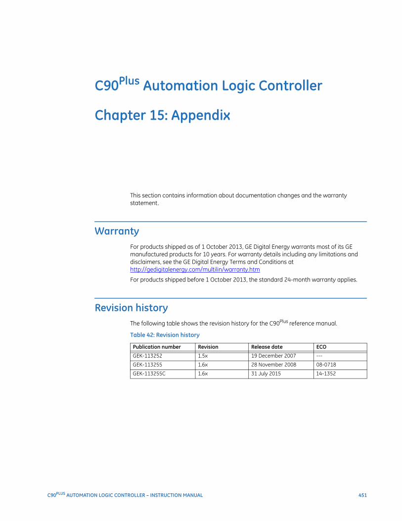
C90PLUS AUTOMATION LOGIC CONTROLLER – INSTRUCTION MANUAL 451
C90Plus Automation Logic Controller
Chapter 15: Appendix
Appendix
This section contains information about documentation changes and the warranty statement.
WarrantyFor products shipped as of 1 October 2013, GE Digital Energy warrants most of its GE manufactured products for 10 years. For warranty details including any limitations and disclaimers, see the GE Digital Energy Terms and Conditions athttp://gedigitalenergy.com/multilin/warranty.htm
For products shipped before 1 October 2013, the standard 24-month warranty applies.
Revision historyThe following table shows the revision history for the C90Plus reference manual.
Table 42: Revision history
Publication number Revision Release date ECO
GEK-113252 1.5x 19 December 2007 ---
GEK-113255 1.6x 28 November 2008 08-0718
GEK-113255C 1.6x 31 July 2015 14-1352

452 C90PLUS AUTOMATION LOGIC CONTROLLER – INSTRUCTION MANUAL
REVISION HISTORY CHAPTER 15: APPENDIX
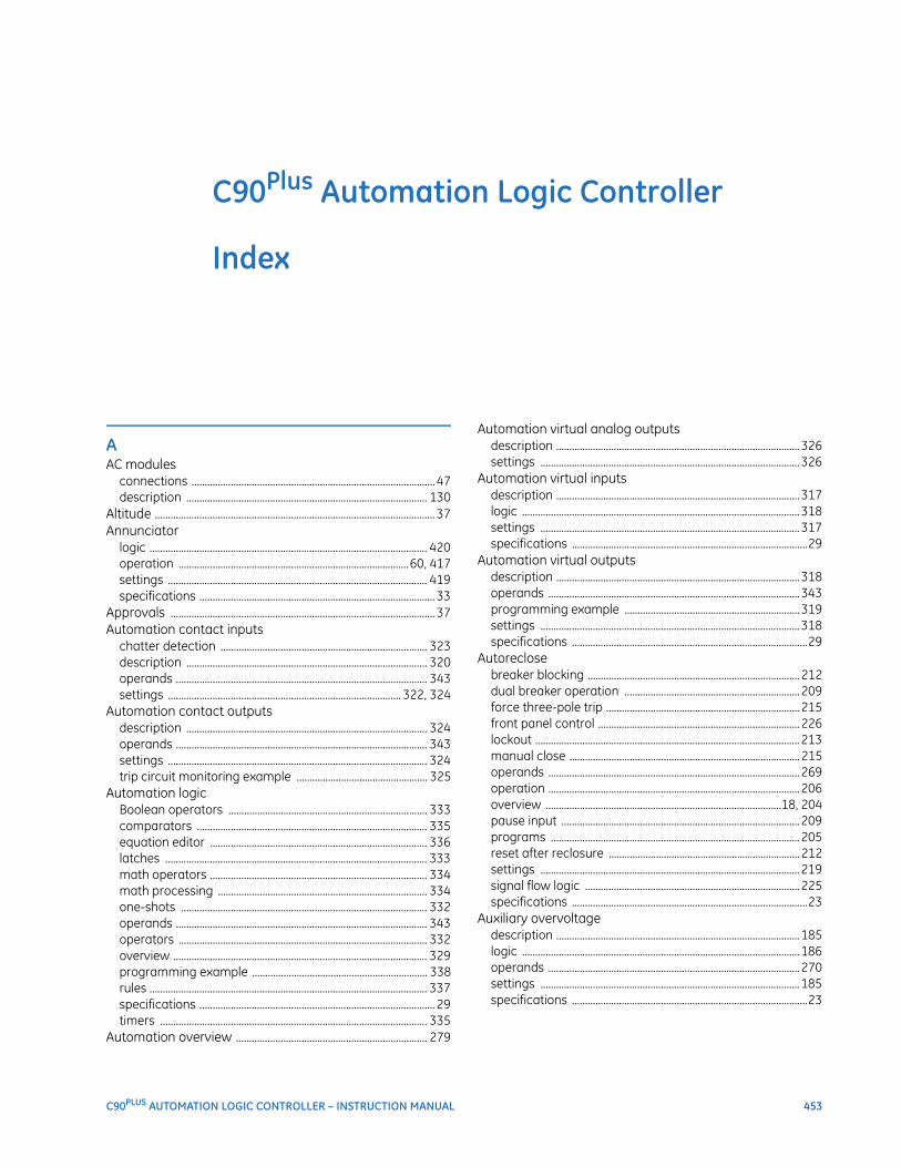
C90PLUS AUTOMATION LOGIC CONTROLLER – INSTRUCTION MANUAL 453
C90Plus Automation Logic Controller
Index
AAC modules
connections ............................................................................................. 47description ............................................................................................ 130
Altitude ........................................................................................................... 37Annunciator
logic .......................................................................................................... 420operation ........................................................................................60, 417settings ................................................................................................... 419specifications .......................................................................................... 33
Approvals ..................................................................................................... 37Automation contact inputs
chatter detection ............................................................................... 323description ............................................................................................ 320operands ................................................................................................ 343settings ......................................................................................... 322, 324
Automation contact outputsdescription ............................................................................................ 324operands ................................................................................................ 343settings ................................................................................................... 324trip circuit monitoring example .................................................. 325
Automation logicBoolean operators ............................................................................ 333comparators ........................................................................................ 335equation editor ................................................................................... 336latches .................................................................................................... 333math operators ................................................................................... 334math processing ................................................................................ 334one-shots .............................................................................................. 332operands ................................................................................................ 343operators ............................................................................................... 332overview ................................................................................................. 329programming example ................................................................... 338rules .......................................................................................................... 337specifications .......................................................................................... 29timers ...................................................................................................... 335
Automation overview ......................................................................... 279
Automation virtual analog outputsdescription .............................................................................................326settings ...................................................................................................326
Automation virtual inputsdescription .............................................................................................317logic ..........................................................................................................318settings ...................................................................................................317specifications ..........................................................................................29
Automation virtual outputsdescription .............................................................................................318operands ................................................................................................343programming example ...................................................................319settings ...................................................................................................318specifications ..........................................................................................29
Autoreclosebreaker blocking .................................................................................212dual breaker operation ...................................................................209force three-pole trip ..........................................................................215front panel control .............................................................................226lockout .....................................................................................................213manual close ........................................................................................215operands ................................................................................................269operation ................................................................................................206overview ..........................................................................................18, 204pause input ...........................................................................................209programs ...............................................................................................205reset after reclosure .........................................................................212settings ...................................................................................................219signal flow logic ..................................................................................225specifications ..........................................................................................23
Auxiliary overvoltagedescription .............................................................................................185logic ..........................................................................................................186operands ................................................................................................270settings ...................................................................................................185specifications ..........................................................................................23
454 C90PLUS AUTOMATION LOGIC CONTROLLER – INSTRUCTION MANUAL
INDEX
Auxiliary undervoltagedescription ............................................................................................ 183logic .......................................................................................................... 185operands ................................................................................................ 270settings ................................................................................................... 184specifications ..........................................................................................23
BBattery monitor
description ............................................................................................ 351indications ............................................................................................. 351logic .......................................................................................................... 354operands ................................................................................................ 356settings ................................................................................................... 352specifications ..........................................................................................31wiring ....................................................................................................... 352
Breaker arcing currentlogic .......................................................................................................... 350measurement ...................................................................................... 348operands ................................................................................................ 357settings ................................................................................................... 349specifications ..........................................................................................31
Breaker configurationdescription ............................................................................................ 227logic .......................................................................................................... 231operands ................................................................................................ 270settings ................................................................................................... 227
Breaker controldescription ............................................................................................ 281logic .......................................................................................................... 283operands ................................................................................................ 343settings ................................................................................................... 281specifications ..........................................................................................29
Breaker failuredetermination ...................................................................................... 188initiation stage .................................................................................... 187logic .......................................................................................................... 193operands ................................................................................................ 271overview ..........................................................................................18, 186settings ................................................................................................... 189specifications ..........................................................................................24
Breaker flashoverdescription ............................................................................................ 235logic .......................................................................................................... 237operands ................................................................................................ 271settings ................................................................................................... 236six VT application ............................................................................... 239specifications ..........................................................................................24three VT application ......................................................................... 239
Breaker interlockingdescription ............................................................................................ 284logic .......................................................................................................... 286operands ................................................................................................ 343settings ................................................................................................... 284specifications ..........................................................................................29
CCautions ........................................................................................................... 1Certifications ...............................................................................................37Communications
overview ............................................................................................ 22, 73Contact inputs
connections .............................................................................................49specifications .................................................................................. 24, 34
Contact outputsconnections .............................................................................................49specifications ..........................................................................................34
Controlfront panel display ................................................................................57
CT/VT channel configuration ..........................................................137Current cut-off level .............................................................................132Current inputs
settings ....................................................................................................131Current metering
specifications ..........................................................................................31
DData logger
channel configuration ......................................................................410operands ................................................................................................414overview .................................................................................................408settings ....................................................................................................408specifications ..........................................................................................31
Dielectric strength ...................................................................................44Digital counters
description .............................................................................................240logic ..........................................................................................................242operands ................................................................................................272settings ....................................................................................................240
Digital fault recorderdescription .............................................................................................359front panel display ................................................................................58overview ....................................................................................................21
Dimensions ..................................................................................................39Disconnect configuration
description .............................................................................................286logic ..........................................................................................................289operands ................................................................................................344settings ....................................................................................................286
Disconnect controldescription .............................................................................................291logic ..........................................................................................................293operands ................................................................................................344settings ....................................................................................................291specifications ..........................................................................................30
Disconnect interlockingdescription .............................................................................................294logic ..........................................................................................................295operands ................................................................................................344settings ....................................................................................................294specifications ..........................................................................................30
INDEX
C90PLUS AUTOMATION LOGIC CONTROLLER – INSTRUCTION MANUAL 455
Disturbance detectordescription ............................................................................................ 139operands ................................................................................................ 277specifications .......................................................................................... 24
Disturbance recorderanalog channels ................................................................................. 379description ............................................................................................ 373digital channels .................................................................................. 378front panel indications .......................................................... 360, 375logic .......................................................................................................... 377settings ................................................................................................... 376specifications .......................................................................................... 32
DNP protocolsettings ...................................................................................................... 85user point list .......................................................................................... 89
EElectrical installation .............................................................................. 42Energy metering
overview .................................................................................................... 21specifications .......................................................................................... 31
Equipment managerdescription ............................................................................................ 347front panel interface ........................................................................... 60operands ................................................................................................ 356overview ................................................................................................. 347
Ethernetactual values ........................................................................................... 82connections ............................................................................................. 44settings ...................................................................................................... 76specifications .......................................................................................... 35
Event recorderdescription ............................................................................................ 359front panel display ............................................................................ 359overview .................................................................................................... 21specifications .......................................................................................... 32
FFault locator
overview .................................................................................................... 21specifications .......................................................................................... 32
Fault reportdescription ............................................................................................ 360logic .......................................................................................................... 364operation ............................................................................................... 361settings ................................................................................................... 362specifications .......................................................................................... 32
Fault reportsoverview .................................................................................................... 21
FlexCurvesdescription .............................................................................................243equations ...............................................................................................145recloser curve editing ......................................................................245recloser curve example ...................................................................246settings ...................................................................................................243software features ...............................................................................244specifications ..........................................................................................24
FlexLogicspecifications ..........................................................................................28
FlexMatrixdescription .............................................................................................199logic ..........................................................................................................202operands ................................................................................................272settings .........................................................................................199, 200specifications ..........................................................................................24
FlexStatesactual values ........................................................................................118description .............................................................................................118settings ...................................................................................................118
Force contact inputs ...........................................................................443Force contact outputs ........................................................................444Frequency metering
specifications ..........................................................................................31Frequency rate of change load shedding
logic ..........................................................................................................317operands ................................................................................................345settings ...................................................................................................315specifications ..........................................................................................30
Front panel HMIspecifications ..........................................................................................33
Front panel interfaceoperation ...................................................................................................56
GGGIO1 settings ........................................................................................113GGIO2 settings ........................................................................................113GGIO4 settings ........................................................................................114GOOSE settings .........................................................................................93Ground instantaneous overcurrent
description .............................................................................................166logic ..........................................................................................................168operands ................................................................................................272settings ...................................................................................................166specifications ..........................................................................................25
Ground time overcurrentdescription .............................................................................................164logic ..........................................................................................................166operands ................................................................................................272settings ...................................................................................................164specifications ..........................................................................................25
Grouped elements ................................................................................140GSSE settings ..............................................................................................93Guarantee .................................................................................................451
456 C90PLUS AUTOMATION LOGIC CONTROLLER – INSTRUCTION MANUAL
INDEX
IIEC 60870-5-104
actual values ...........................................................................................93IEC 60870-5-104 protocol
point lists ...................................................................................................92settings ......................................................................................................90
IEC 61850actual values ........................................................................................ 117DNA assignments .............................................................................. 101GGIO1 settings .................................................................................... 113GGIO2 settings .................................................................................... 113GGIO4 settings .................................................................................... 114GSSE/GOOSE configuration .............................................................93logical node prefixes ........................................................................ 108MMXU deadbands ............................................................................. 110overview ....................................................................................................93remote devices ......................................................................................99remote inputs ...................................................................................... 101remote outputs ......................................................................... 103, 104report control configuration ......................................................... 116server settings ..................................................................................... 106
Inspection checklist ...................................................................................1Installation
electrical ....................................................................................................42physical ......................................................................................................39settings ................................................................................................... 129
IRIG-Bconnections .............................................................................................45specifications ..........................................................................................35
LLoad shedding
sources ................................................................................................... 311specifications ..........................................................................................30
Local-remoteoperands ................................................................................................ 345
Local-remote controldescription ............................................................................................ 298logic .......................................................................................................... 299settings ................................................................................................... 298
MMetering
front panel display ...............................................................................57overview ....................................................................................................20sources ................................................................................................... 385
Metering logicoperands ...................................................................................... 125, 414
Mimic diagramsettings ................................................................................................... 426
MMXU deadbands ................................................................................ 110
Modbus protocolsettings .......................................................................................................83specifications ..........................................................................................36user map ...................................................................................................84
Module withdrawal .................................................................................40
NNegative-sequence directional overcurrent
description .............................................................................................172logic ..........................................................................................................175settings ....................................................................................................173specifications ..........................................................................................25
Negative-sequence instantaneous overcurrentdescription .............................................................................................170logic ..........................................................................................................171operands ................................................................................................273settings ....................................................................................................170specifications ..........................................................................................25
Negative-sequence overvoltagedescription .............................................................................................182logic ..........................................................................................................183operands ................................................................................................273settings ....................................................................................................182specifications ..........................................................................................26
Negative-sequence time overcurrentdescription .............................................................................................168logic ..........................................................................................................169operands ................................................................................................273settings ....................................................................................................168specifications ..........................................................................................26
Network settings ......................................................................................76Network topologies .................................................................................73Neutral directional overcurrent
description .............................................................................................158logic ..........................................................................................................163operands ......................................................................................272, 274settings ....................................................................................................160specifications ..........................................................................................26
Neutral instantaneous overcurrentdescription .............................................................................................156operands ................................................................................................273settings ....................................................................................................157specifications ..........................................................................................26
Neutral overvoltagedescription .............................................................................................180logic ..........................................................................................................182operands ................................................................................................273settings ....................................................................................................181specifications ..........................................................................................27
Neutral time overcurrentdescription .............................................................................................154logic ................................................................................................156, 158operands ................................................................................................273settings ....................................................................................................155specifications ..........................................................................................27
Nominal frequency ...............................................................................135
INDEX
C90PLUS AUTOMATION LOGIC CONTROLLER – INSTRUCTION MANUAL 457
Non-volatile latchesdescription ............................................................................................ 263logic .......................................................................................................... 264operands ................................................................................................ 272settings ................................................................................................... 263specifications .......................................................................................... 27
Notes ..................................................................................................................1
OOperating temperature ........................................................................ 37
PPassword security
operation ............................................................................................... 438settings ................................................................................................... 436
Per-unit quantities ............................................................................... 128Phase directional overcurrent
description ............................................................................................ 151logic .......................................................................................................... 154operands ................................................................................................ 274settings ................................................................................................... 152specifications .......................................................................................... 27
Phase instantaneous overcurrentdescription .................................................................................. 149, 150operands ................................................................................................ 274settings ................................................................................................... 149specifications .......................................................................................... 27
Phase overvoltagedescription ............................................................................................ 179logic .......................................................................................................... 180operands ...................................................................................... 275, 276settings ................................................................................................... 179specifications .......................................................................................... 28
Phase time overcurrentdescription ............................................................................................ 146logic .......................................................................................................... 148operands ................................................................................................ 275settings ................................................................................................... 146-specifications ........................................................................................ 28
Phase undervoltagedescription ............................................................................................ 177logic .......................................................................................................... 178operands ................................................................................................ 276settings ................................................................................................... 177specifications .......................................................................................... 28
Phasor measurement unitaccuracy .................................................................................................407calibration ..............................................................................................387communications .................................................................................388configuration ........................................................................................386current triggering ...............................................................................395description .............................................................................................385frequency triggering .........................................................................392network reporting ..............................................................................404one-shot settings ...............................................................................405operands ......................................................................................414, 415power triggering .......................................................................396, 398recording ................................................................................................400user trigger ............................................................................................391voltage triggering ..............................................................................393
Physical installation ................................................................................39Power cut-off level ...............................................................................134Power metering
specifications ..........................................................................................32Power supply
connections .............................................................................................46specifications ..........................................................................................35
Product information ...............................................................................62Production tests ........................................................................................36Protection
grouped elements .............................................................................140overview .................................................................................................127
Protection contact inputschatter dete ction ..............................................................................253configuration ........................................................................................250operands ................................................................................................271settings ...................................................................................................252
Protection contact outputssettings ...................................................................................................254
Protection FlexElementsdescription .............................................................................................264logic ..........................................................................................................269operands ................................................................................................272settings ...................................................................................................264
Protection FlexLogicdescription .............................................................................................257equation editor ....................................................................................261gates ........................................................................................................260operands ................................................................................................269operators ...............................................................................................260rules ..........................................................................................................261securing and locking ...........................................................................68timers .......................................................................................................262
Protection virtual inputsdescription .............................................................................................247logic ..........................................................................................................248settings ...................................................................................................247specifications ..........................................................................................28
Protection virtual outputsdescription .............................................................................................249settings ...................................................................................................249specifications ..........................................................................................28
458 C90PLUS AUTOMATION LOGIC CONTROLLER – INSTRUCTION MANUAL
INDEX
RReal time clock
settings ................................................................................................... 119Rear terminal layout ..............................................................................41Remote devices
description ...............................................................................................99settings ......................................................................................................99
Remote double-point status inputsoperands ................................................................................................ 125
Remote DPS inputssettings ......................................................................................... 102, 105
Remote inputsprotection specifications ...................................................................29settings ................................................................................................... 101specifications ..........................................................................................36
Remote outputsDNA bit pairs ........................................................................................ 104protection specifications ...................................................................29specifications ..........................................................................................36UserSt bit pairs .................................................................................... 104
Repair ........................................................................................................... 451RS485
connections .............................................................................................44settings ................................................................................................... 123specifications ..........................................................................................36
SSecurity
password security ............................................................................. 435Selector switch
description ............................................................................................ 305events ...................................................................................................... 310logic .......................................................................................................... 311operands ................................................................................................ 345operation ............................................................................................... 305settings ................................................................................................... 307specifications ..........................................................................................30
Self-test summary ...................................................................................62Self-tests
error messages ................................................................................... 446Setting files
traceability ...............................................................................................69Setting groups
FlexLogic control ................................................................................ 199operands ................................................................................................ 277settings ................................................................................................... 197
Setting templatesediting ........................................................................................................65enabling ....................................................................................................64introduction .............................................................................................63removing ...................................................................................................68security ......................................................................................................66viewing .......................................................................................................66
Shared operandsautomation ...........................................................................................328digital fault recorder .........................................................................382equipment manager .........................................................................355metering .................................................................................................413protection ....................................................................................124, 256
SNTP protocolsettings .......................................................................................................81
Sourcesexample configuration ....................................................................139overview .................................................................................................136protection ..............................................................................................138
Synchrocheckdescription .............................................................................................300logic ..........................................................................................................303operands ................................................................................................346overview ....................................................................................................19settings ....................................................................................................301specifications ..........................................................................................30
Synchrophasorscalibration ..............................................................................................387communications .................................................................................388configuration ........................................................................................386current triggering ...............................................................................395df/dt triggering ....................................................................................398frequency triggering .........................................................................392network reporting ..............................................................................404one-shot settings ...............................................................................405phasor measurement unit .............................................................385power triggering .................................................................................396recording ................................................................................................400user trigger ............................................................................................391voltage triggering ...............................................................................393
System frequency .................................................................................135
TTest mode
force contact inputs ..........................................................................443force contact outputs ......................................................................444overview .................................................................................................443
TFTP protocolsettings .......................................................................................................80
Time overcurrent curvesdefinite time curve .............................................................................145FlexCurves .............................................................................................145I2t curves ................................................................................................145IAC curves ..............................................................................................143IEC curves ..............................................................................................142IEEE curves ............................................................................................141overview .................................................................................................140recloser curves ....................................................................................146
INDEX
C90PLUS AUTOMATION LOGIC CONTROLLER – INSTRUCTION MANUAL 459
Transient recorderanalog channels ................................................................................. 371description ............................................................................................ 364digital channels .................................................................................. 369front panel indications .................................................................... 366logic .......................................................................................................... 368overview .................................................................................................... 22settings ................................................................................................... 367specifications .......................................................................................... 33
Type tests ..................................................................................................... 36Typical wiring ............................................................................................. 43
UUnderfrequency load shedding
logic ................................................................................................ 314, 315operands ................................................................................................ 346settings ................................................................................................... 313specifications .......................................................................................... 30
Undervoltage load sheddingoperands ................................................................................................ 346settings ................................................................................................... 314specifications .......................................................................................... 31
USB portspecifications .......................................................................................... 36
User-programmable self-testssettings ................................................................................................... 121
VVoltage cut-off level ............................................................................ 134Voltage elements .................................................................................. 176Voltage inputs
settings ................................................................................................... 132Voltage metering
specifications .......................................................................................... 32VT fuse failure
description ............................................................................................ 202logic .......................................................................................................... 203operands ................................................................................................ 277settings ................................................................................................... 203specifications .......................................................................................... 29
WWarnings .........................................................................................................1Warranty .................................................................................................... 451Wiring ............................................................................................................. 43
ZZero-sequence CBCT .............................................................................47

460 C90PLUS AUTOMATION LOGIC CONTROLLER – INSTRUCTION MANUAL
INDEX