automotive research user handbookdownload.ni.com/.../automotive_research_handbook.pdf ·...
TRANSCRIPT

Automotive Research User HandbookPROTOTYPES AND TESTBEDS TO VALIDATE THE TRANSPORTATION SOLUTIONS OF TOMORROW

2
ANDY BELL | DIRECTOR OF ACADEMIC PROGRAMSWithin the next 10 years, we will see remarkable change in the automotive industry. From improved engine efficiency to autonomous vehicles to electrification, innovation will begin in academic institutions around the world. NI solutions integrate hardware and software to help automotive scientists and engineers take accurate measurements, perform hardware-in-the-loop (HIL) simulation, and rapidly prototype new ideas.
This book includes a select set of examples curated to show how researchers and industrial partners are delivering on the innovation needed to change the world of transportation. Researchers are investigating the novel and the innovative, and we are proud to partner with them to make their work possible. To learn more about how NI partners with academic researchers, visit ni.com/research.

3
Table of Contents
Hardware-in-the-Loop Testbed for Sensor Fusion-Based ADAS .......................................................................................................... 4
Data Acquisition and Control of a Hydrogen Diesel Dual Fuel Engine ............................................................................................... 6
Replicating Urban Vehicular Network Performance in Lab Settings .................................................................................................... 8
HIL Simulation Generates Loads Equivalent to Those of Real Roads ................................................................................................10
Building an Aston Martin Race Engine Vibration Analysis System .....................................................................................................12
Full-Scale Simulator for Connected and Autonomous Vehicles ..........................................................................................................14
©2018 National Instruments. All rights reserved. CompactRIO, LabVIEW, National Instruments, NI, ni.com, and USRP are trademarks of National Instruments. Other product and company names listed are trademarks or trade names of their respective companies. 32890
4
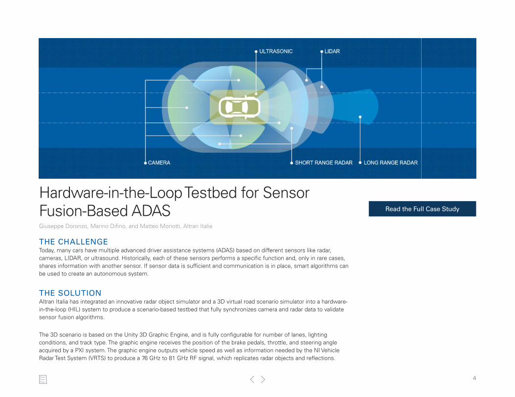
Hardware-in-the-Loop Testbed for Sensor Fusion-Based ADASGiuseppe Doronzo, Marino Difino, and Matteo Moriotti, Altran Italia
Read the Full Case Study
THE CHALLENGEToday, many cars have multiple advanced driver assistance systems (ADAS) based on different sensors like radar, cameras, LIDAR, or ultrasound. Historically, each of these sensors performs a specific function and, only in rare cases, shares information with another sensor. If sensor data is sufficient and communication is in place, smart algorithms can be used to create an autonomous system.
THE SOLUTIONAltran Italia has integrated an innovative radar object simulator and a 3D virtual road scenario simulator into a hardware-in-the-loop (HIL) system to produce a scenario-based testbed that fully synchronizes camera and radar data to validate sensor fusion algorithms.
The 3D scenario is based on the Unity 3D Graphic Engine, and is fully configurable for number of lanes, lighting conditions, and track type. The graphic engine receives the position of the brake pedals, throttle, and steering angle acquired by a PXI system. The graphic engine outputs vehicle speed as well as information needed by the NI Vehicle Radar Test System (VRTS) to produce a 76 GHz to 81 GHz RF signal, which replicates radar objects and reflections.

5
SENSOR FUSION IN TODAY’S VEHICLESSensor fusion can be relevant with all types of sensors. A typical example is the fusion of information provided by a front camera and a front radar. A camera that works in the visible spectrum has problems in several conditions like rain, dense fog, sun glare, and absence of light, but it is highly reliable when recognizing colors (for example, road markings). Radar, even at low resolution, is useful for detecting distance and is not sensitive to environmental conditions.
Typical ADAS functions that use the sensor fusion of front camera and radar include:■ Adaptive Cruise Control (ACC)—Adapts speed to traffic conditions. Speed is reduced when the distance to
the vehicle ahead drops below the safety threshold. When the road clears or distance to the next vehicle is acceptable, the ACC accelerates back to the set speed.
■ Autonomous Emergency Braking (AEB)—Controls the braking system by reducing the speed in the case of a certain collision or by alerting the driver in critical situations.
SCALING UPThe existing setup with one NI Vector Signal Transceiver (VST) and one mmWave head can generate two targets with the same angle of arrival. Thanks to the flexibility of the system, we could easily scale to simulate multiple targets with multiples angles of arrival. A configuration with four VST and four mmWave heads can simulate up to eight different targets with four angles of arrival.
CONCLUSIONADAS systems are safety critical, so the ability to test in the lab before conducting vehicle tests is a crucial step. Validating in this manner means we can anticipate validation prior to the availability of the vehicle to allow corrective actions that otherwise would come too late in the production cycle. Overall development time is greatly reduced because tests can be started before the vehicle is available with a system that can work all day long seven days a week. No-regression tests can be carried out in less time with minimal cost compared to using the assembled vehicle.
As a global leader in engineering and R&D (ER&D) services, Altran offers its clients a new way to innovate by developing the products and services of tomorrow. Altran works alongside its clients on every link in the value chain of their project, from conception to industrialization.
Altran Italia has integrated an innovative radar object simulator and a 3D virtual road scenario simulator into a hardware-in-the-loop (HIL) system to produce a scenario-based testbed that fully synchronizes camera and radar data to validate sensor fusion algorithms.
Test Manager at Altran Italia
Figure 1. ADAS HIL Test Environment
Figure 2. Eight-Target, Four-Angle System Architecture

6
Data Acquisition and Control of a Hydrogen Diesel Dual Fuel Engine Priybrat Sharma and Dr. Atul Dhar, Renewable Fuels and Internal Combustion Engine Lab, Indian Institute
of Technology Mandi
THE CHALLENGECurrent internal combustion engine research is focused on engine performance improvement and emission reduction. Dual fuel engines are proven to address both of these concerns, but they require accurate engine control systems to operate safely. A hydrogen diesel dual fuel engine setup increases safety concerns further. Additionally, measurement instrumentation for such engines during research is a challenge due to the diversity and number of sensors and actuators.
THE SOLUTIONOur aim was to develop a system for fast, reliable, and precise control of a converted dual fuel compression ignition engine.
Read the Full Case Study

7
REQUIREMENTSThe system needed to monitor the crank angle of the engine continually and control the fuel injection timings. It also needed to track and collect the in-cylinder pressure, fuel line pressure, and accelerometer and microphone data. The system needed to be rapidly and easily adaptable for different engines with varying speeds up to 7000 rpm and expandable for exhaust selective catalytic reduction (SCR) system dosing.
SYSTEM ARCHITECTUREThe developed system uses NI FPGA technology to acquire data from the optical encoder, cylinder pressure sensor, fuel line pressure sensor, quarter-inch microphone, and single axis accelerometers. This data is analyzed in real time, and the results are used to control the fuel injection timing and duration using the FPGA.
The FPGA acquires data from the transducers and encoder connected to data acquisition modules. Additionally, we compensated for the lack of a cam angle sensor by instead interpreting an encoder indexing pulse and cylinder pressure data on the FPGA level. The 40 MHz processing speed of the FPGA allows us to achieve a coupled masking of index pulse every other revolution. The data is then transferred to a real-time OS using FIFO. A receiver loop receives the FIFO data and creates a data stream. The data stream then moves the data to a conditioning loop, which de-noises and filters the data. Then it further transfers data to the storage (RAW) and processing loop.
The real-time processing loop runs necessary calculations for cylinder volume, pressure rise rate, heat release rate, the start and end of combustion, mean effective pressure, and cycle-to-cycle variation. This data is displayed using a web user interface and simultaneously recorded in flash memory (pen drive).
WHAT’S NEXTWe’re planning further experimentation using an optimization algorithm-controlled injection timing and duration process. We will then scale up the system to handle a dual-cylinder engine.
The Renewable Fuels and Internal Combustion Engine Lab at IIT Mandi started in 2016 with the goal of testing alternative fuels and developing advanced engine systems and combustion technologies.
“NI LabVIEW and CompactRIO allowed us to develop a reliable, robust, inexpensive, and versatile in-house engine control and data acquisition system in a short time frame of two months.”
Priybrat Sharma, Indian Institute of Technology Mandi
Figure 2. Live Data From the Transducers and Encoder and Averaged Data of 100 Cycles for Pressure Crank Angle, Pressure Volume
Figure 3. Dual Fuel Engine Inside the Test Facility
Figure 1. Schematic of the Control and Data Acquisition System

8
Replicating Urban Vehicular Network Performance in Lab SettingsThomas Blazek and Christoph F. Mecklenbräuker, Institute of Telecommunications (ITC), TU Wien Vienna
THE CHALLENGEThe USA saw an average of 90 deaths on the road per day in 2013. We expect applications based on vehicle-to-vehicle (V2V) and vehicle-to-infrastructure (V2I) communications to play a role in reducing this number greatly. Hence, it is vital to have a good grasp of the possibilities and limits of vehicular communication standards. This is a daunting task, since communication conditions differ greatly from traditional applications. The outdoor environment means that the channel echoes arrive later, resulting in a large delay spread, and the high vehicular speeds introduce challenges in terms of Doppler spectra not seen in relatively static mobile conditions. Therefore, we must thoroughly test the performance of a communication standard before using it on the street. However, conducting such tests on real streets is impractical. The measurements are not repeatable due to too many factors changing on the street. They cannot be conducted on a large scale since this requires blocking streets, and, due to safety aspects, certain scenarios cannot be tested in the real world.
THE SOLUTIONThe basic solution is to take the evaluation off the street by emulating the vehicular channel. For this, we had access to draft channel models defined by the ETSI standard for intelligent transport systems at 5 GHz (ITS-G5), which is based on tapped
Read the Full Case Study

0 2 4 6 8 10
Time [s]
0.0
0.2
0.4
0.6
0.8
1.0
P(E
)
9
delay lines. Our first approach used off-the-shelf modems. However, these solutions did not offer the configuration, control, and inspection we required. For example, the channel models defined a half-bathtub Doppler shape, which was not implementable on off-the-shelf channel emulators.
SYSTEM ARCHITECTUREWe decided to replace all components with NI USRP RIO devices and the LabVIEW Communications 802.11 Application Framework. Only small modifications are necessary to adjust it to 11p-compliant communications. The channel emulator we designed allows a 10-tap tapped delay line, and the position of the taps, as well as the small-scale fading coefficients, can be updated in real time. Our update rate for the parameters is given at 10 kHz. This relates to a movement of less than 5 cm (2 in.) for a vehicle going 161 km/h (100 mph), ensuring that we capture even small changes of the channel. The emulation bandwidth is 20 MHz, which is plenty for a communication standard working at a bandwidth of 10 MHz.
Using this setup, we can send arbitrary payload patterns with defined transmission times and packet lengths as well as log reception information over channels that can be set to arbitrary behaviors. Our first evaluation case was on point-to-point communication under six stationary channel models. We used compressed sensing methodologies to find optimal fits of channel sounder measurements and then produced time-variant nonstationary channels.
WHAT’S NEXTBecause of the software-defined nature of the emulator, we can easily switch the frequency or communications standard to conduct similar analyses on a different protocol, which is impossible to do with off-the-shelf hardware. We are providing thorough and reproducible throughput results for vehicular communications conducted on real hardware, which has not been published in this form yet. In the near future, we are planning to extend to other standards, such as LTE, and use the emulator in a 60 GHz frequency band
T. Blazek, G. Ghiaasi, C. Backfrieder, G. Ostermayer, C. F. Mecklenbräuker, “IEEE 802.11p Performance for Vehicle-to-Anything Connectivity in Urban Interference Channels,” accepted for presentation and Proceedings entry in EuCAP 2018
“Finally, we introduced city maps and mobility simulators into the setup. We use vehicular traces generated for Linz, a city in Austria, to analyze the worst-case scenario, a massive traffic jam.”
Thomas Blazek, Institute of Telecommunications, TU Wien
Figure 2. Symbol Decoding Before and After Channel Equalization
Figure 1. In this setup for network measurements, the picture displays two channel emulators (Em1, Em2), one transmitter (Tx), and one node configured as an interferer and receiver (Rx/Int).

10
HIL Simulation Generates Loads Equivalent to Those of Real RoadsDaisuke Umiguchi, Subaru Corporation; Kyosuke Tomoyasu, Virtual Mechanics Corporation; and Sho Abe, HORIBA Ltd.
Read More About HIL Testing at Subaru
THE CHALLENGEDeveloping a car involves test-drives on test courses or public roads, which are susceptible to factors such as weather and varying road surface conditions. This makes conducting reproducible tests on actual roads extremely difficult. Furthermore, re-creating road surface conditions to conduct the required tests in a timely manner is challenging.
THE SOLUTIONWe combined a dynamometer with a hardware-in-the-loop (HIL) simulator to perform operations indoors, where we were unaffected by the weather, and to generate loads equivalent to actual roads. We used a HORIBA dynamometer and CarSim from Virtual Mechanics Corporation for the simulator software. In addition, we used NI PXI hardware and LabVIEW software to build the HIL system.

11
REAL-TIME CONTROLThe driving system sends out the calculated values to the HIL system in real time to create closed-loop control between models on the HIL system and driving system. As a result, the HIL interaction system is able to apply the appropriate load to the vehicle in real time.
The dynamometer applies a load to each of the wheels via multiple motors, so we can apply an arbitrary load to each of the wheels in real time. The HIL system uses the simulation values to create mock conditions that replicate driving on a test course or public road.
RE-CREATING MALICIOUS SCENARIOSWith this system, we can easily simulate conditions that are impossible to produce on actual roads. For example, a user could create conditions for an icy road surface with a 30 percent gradient. If later tests required the gradient to be increased to 40 percent, this could be achieved instantly by modifying the CarSim settings. Tests under conditions that are highly unlikely on actual roads (so-called malicious tests) can also be performed.
In addition, with CarSim, we can generate loads that simulate public roads. In this case, we must measure the gradient and cant (height difference between the interior and exterior of a curved line) of various places along the public road. We then use these results to create a model that can further improve the realism of the test scenario.
WHAT’S NEXTIn the future, Subaru plans to leverage Horiba’s Test Automation System (STARS) to automate testing. While humans will probably need to monitor operations closely in the beginning, we hope that this task will eventually be replaced by remote monitoring. Upon implementation, a quarter reduction in the number of operators (to conduct the test) is expected.
Schematic of the Developed System
“The use of NI products proved to be a key factor in shortening the development period. In fact, the implementation of the HIL system was completed in just 1–2 weeks.”Sho Abe, HORIBA Ltd.
12
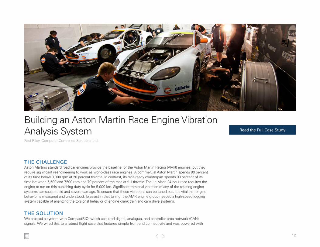
Building an Aston Martin Race Engine Vibration Analysis SystemPaul Riley, Computer Controlled Solutions Ltd.
THE CHALLENGEAston Martin’s standard road car engines provide the baseline for the Aston Martin Racing (AMR) engines, but they require significant reengineering to work as world-class race engines. A commercial Aston Martin spends 90 percent of its time below 3,000 rpm at 20 percent throttle. In contrast, its race-ready counterpart spends 90 percent of its time between 5,500 and 7,500 rpm and 70 percent of the race at full throttle. The Le Mans 24-hour race requires the engine to run on this punishing duty cycle for 5,000 km. Significant torsional vibration of any of the rotating engine systems can cause rapid and severe damage. To ensure that these vibrations can be tuned out, it is vital that engine behavior is measured and understood. To assist in that tuning, the AMR engine group needed a high-speed logging system capable of analyzing the torsional behavior of engine crank train and cam drive systems.
THE SOLUTIONWe created a system with CompactRIO, which acquired digital, analogue, and controller area network (CAN) signals. We wired this to a robust flight case that featured simple front-end connectivity and was powered with
Read the Full Case Study

13
a 12 V supply from the car’s own battery. Critically, we also used a temporary battery backup system to maintain acquisition during the power loss experienced when the ignition key was turned.
SYSTEM OPERATIONUpon boot up, the CompactRIO system begins headless data acquisition, analysis, and logging. A built-in Wi-Fi router allows us to connect a laptop for remote configuration and monitoring. This means the entire system can be wired to car-mounted transducers and operated from a laptop in the passenger seat. An engineer can also connect the system to a dynamometer while making real-time adjustments to the engine control unit (ECU).
The Mobile Daquire device, which provides 25 ns resolution acquisition and analysis of vibrations in key engine and drive train components, can be fully synchronized with a variety of mixed measurements to precisely investigate resonances over the speed range of the engine.
WHAT’S NEXTThe system extensibility provided a clear approach to accommodating synchronized acquisition of up to 300 high-speed CAN channels. Looking to the future, we hope to take advantage of emerging technologies. For example, we can supply a low-cost upgrade to AMR that delivers status and acquisition control on a tablet device that is located alongside the vehicle dash. With the intuitive Data Dashboard app, AMR can display different live test data streams as required and can customise the user interface to include items such as new sponsor logos.
AMR has competed in the Le Mans race since 2005. AMR now competes in the latest Grand Touring Endurance (GTE) category with the Aston Martin V8 Vantage, which took home the prize at the opening round of the GTE World Endurance Championship series in 2013 at Silverstone.
“Significant torsional vibration of any of the rotating engine systems can cause rapid and severe damage. To ensure that these vibrations can be tuned out, it is vital that engine behavior is measured and understood.”
Paul Riley, Computer Controlled Solutions Ltd.
Figure 1. Batch Processing Software Provides an Order Analysis Quick View
Figure 2. The CCS Mobile Daquire System, Based on the NI CompactRIO Platform

14
Full-Scale Simulator for Connected and Autonomous VehiclesGunwant Dhadyalla, WMG, University of Warwick
THE CHALLENGEWe cannot build confidence in connected and autonomous vehicles (CAVs) with physical road tests alone.
THE SOLUTIONWMG’s 3xD Simulator for intelligent vehicles aims to provide an innovative platform to bridge the gap between traditional hardware-in-the-loop (HIL) test and road-based field tests. The simulator provides a drive-in, driver-in-the-loop, multiaxis driving experience, hence the name 3xD Simulator.
ISOLATIONThe WMG 3xD Simulator is housed in an RF shielded room (Faraday cage) that can house a full vehicle. Through this complete isolation, external RF signals are blocked to allow the emulation of the complete RF environment, the visual environment for the driver, and other sensory systems to the vehicle’s electronic systems.
Read the Full Case Study

15
We wanted to provide full emulation to the vehicle’s and driver’s sensors, which include not only LIDAR, RADAR, and scenery generation (visual) but also Bluetooth, 4G, V2X, and most importantly location information using GNSS.
When emulating satellite constellations that provide position information (GNSS), a test engineer has to distinguish between different environments. Driving in urban and intra-urban motorways inhibits different signal characteristics, such as signal strengths, reflections, and number of satellites that are visible.
IMMERSIONSeveral other simulators are available, so we wanted to provide a first-of-its-kind facility that can be used to test, verify, and validate new technology and full systems in a connected and immersive way. Our aim is to not only generate the scene around the vehicle (stimulate sensors) but also integrate it with the RF environment, including satellite information. This would enable a driver to completely be immersed and in the loop and enable vehicle manufacturers to test their vehicles earlier in the design phase to avoid costly design changes caused by defects found later.
CONCLUSIONThe simulator provides a real-time, safe, controlled, and repeatable physical environment, which allows for not only the sensor and communications to be in the loop but the driver as well.
This gives insight into how both the user and the system (vehicle) interacts with their environment within a safe, controlled, and repeatable environment. For example, we can test how the driver reacts when we add noise to the car stereo or how the vehicle reacts when satellite signals are lost in an urban environment.
WHAT’S NEXTThrough the flexibility of the platform, 3G, 4G/LTE, Bluetooth, or digital radio can also be generated. In the future, we can use the platform together with NI USRP devices to generate V2X for testing V2I and V2V HIL within a synthetic environment.
As part of WMG’s goal to bridge the gap between industry and academia, it hosts the National Automotive Innovation Centre (NAIC) to accelerate novel collaborative R&D in the automotive sector such as the work on CAV virtual verification and validation.
“The WMG team plans to emulate current and future [satellite] constellations, for example, what you will see when you drive in Tokyo in 2025.”Gunwant Dhadyalla, WMG, University of Warwick
Figure 1. The 3xD Simulator allows us to test designs earlier in the V-cycle. Image courtesy of WMG.
Figure 2. The 3xD Simulator Architecture. Image courtesy of WMG.