autonomous drones for next generation visual inspection for inspection - 08... · multicopter...
TRANSCRIPT

Autonomous Drones for Next Generation Visual Inspection
Professor Gareth Pierce, Dr Gordon Dobie, Dr Charles Macleod, Dr Kenneth Burnham, Dayi Zhang, Robert Watson, William Jackson, Liam McDonald, Daniel McMahon
Department of Electronic & Electrical Engineering Centre for Ultrasonic Engineering
Multicopter Workshop – Manchester, Monday 9 July 2018

A brief history of robotics research in CUE • 2006 – SGP joined CUE to work on robotics for NDE
(non-destructive evaluation) • Numerous projects run through RCNDE
– Mobile robotics, leading to commercialisation with Eddyfi / Silverwing (Oil and Gas) and Nuclear site inspections
– Manufacturing robotics, leading to scale up and commercialisation through AFRC and aerospace partners
• Identified need for accurate positioning and data registration as essential for robotic NDE and inspection
• 2009 - Established FIRST laboratory to support NDE research:
– Enabled state of the art positioning equipment to be purchased (VICON and Leica Laser Tracker) – allows accurate 6DOF positioning measurements to be performed
– Wheeled robotic platforms and UAV research – Manufacturing robotics (6/7 axis systems)
Robotsusedasadeliveryplatform,forNDEandothersensing,includingmetrology

Indoor Positioning Systems Verification of tracking algorithms
Vicon Motion Tracker • Operating Principles
– 12 cameras bound tracking volume – Infra-red retroreflectors mounted on
object – Reprojection and triangulation of
markers from image planes • Volume Coverage
– Physical assessment – Correlation to accuracy
• Modelling – Interpretation of calibration output – Camera observability projection
Leica AT901B Laser Tracker • Operating Principles
– 2 axis rotary position encoder – Absolute Interferometer Module (AIFM) – Directional retroreflective sphere – Accuracy of ±(15 µm + 6 µm/m) over 80
m radius
1. Vicon T160 Camera, Available:http://mars.cs.umn.edu/images/research_platforms/vicon-1.png,Accessed: 05/12/2017

Flexible robotics Integrated inspection
Autonomousinspectiontoreducecycletimeforaircraftproduction(A32x,737series)
In-process
inspectionforadditive
manufacturingandmaterial
joining
Autonomous
inspectionforhighvolumelowcostautomotive
remanufacture
UAVcontrolandpathplanningforassetinspection
Autonomousinspectionforhazardous
environments
InspectionforHighValueManufacture
InspectionforAdditiveManufacture&MaterialsJoining
InspectionforRemanufacture
AssetInspection&Decommissioning
Large data volumes
Flexibleprogrammingformultiplerobotplatforms
Robotics,Automation&Inspection:THEMES

UAV Inspection Applications Driven from RCNDE partners
• Buildings, civils • Nuclear applications
– Civil – Storage
• Wind turbine • Offshore, oil and gas • Power distribution
networks • Aircraft routine
inspection
S.Omari,P.Gohl,M.Burri,M.Achtelik,andR.Siegwart,“Visualindustrialinspectionusingaerialrobots,”inProceedingsofthe20143rdInternationalConferenceonAppliedRoboticsforthePowerIndustry,2014,pp.1–5.
AutonomousvisualnavigationofUnmannedAerialVehicleforwindturbineinspectionby:MartinStokkeland,KristianKlausen,TorA.Johansen,2015InternationalConferenceonUnmannedAircraftSystems(ICUAS).

UAV Inspection Approach • Feasibility study with EDF Energy, AFRC and
GAIA Wind • Using pre-planned flight path (not fully
autonomous) • Use 3D reconstructed model for an overview of
the surface while conventional UAV scan provides individual pictures
• 3.1m height • 386mm wide (top);
619mm wide (bottom)
• Circular around the blade • Radius of top circle:
1150mm • Radius of bottom circle:
1250mm • Auto Take-off and landing

Reference model comparison
• GOM ATOS Triple Scan used to capture reference standard model of the blade
• Initially used manually captured images and used Agisoft Photoscan to build 3D mesh model of blade
• Validated performance of model meshing without the influence of the delivery platform
Dense point cloud → • Estimated camera positions
Mesh → • 3D polygon of object surface
Camera alignment • Sparse point cloud

Comparison of visual profile with 3D reference model
Alignment GOMInspect
DeviationMap
3DReferenceModel
VisualReconstruction
Verifiesperformanceofmeshingalgorithm…nowuseUAVplatformtoacquiredata

UAV Blade scan - video

UAV blade scan - effect of lighting and shutter speed
Deviationmapsofthereconstructedmodelcapturedindifferentlightintensity(a)30msshutterwithextralight,(b)30msshutterambientlight,(c)60msshutterambientlight
30msshutterExtralight
30msshutterAmbientlight
60msshutterAmbientlight
StandardDeviation(mm) 1.56 2.46 1.97 MeanError(mm) 0.3853 0.6493 0.4571

Laser Scanner for Alignment
• A laser scanner (Hokuyo URG-04LX) is mounted on top of the UAV measure the alignment error and displacement from target
• The distance measurements maintain the UAV in a constant offset and optimise the camera focusing.
• Allows UAV trajectory to follow the blade geometry.
11

12
Laser Scanner for Alignment

UAV Flight Path
13
Prior defined path
Laser compensated path

Results with/without Laser Deviation Map Comparison
14
Standard Deviation (mm) 1.56 1.24 Mean Error (mm) 0.3853 0.3252 Peak to Peak Error (mm) 13.56 5.71
Without Laser With Laser
Results without laser reconstruction come from images with circular flight path. The camera is 30ms shutter time and with external lights.

Results with/without Laser Texture Comparison
15
Without Laser With Laser
Improvementinfocalperformancewithmaintainingconstantstand-offdistance

Results with Laser Scanner Filtered Images
16
• The camera captured multiple images in the similar poses.
• The results are based on the set of images with laser scanner. And the local best images are selected and imported to the software for the reconstruction.
Original Filtered
Standard Deviation (mm) 1.24 1.20
Mean Error (mm) 0.3252 0.2282
Peak to Peak Error (mm) 5.71 4.27

UAV platforms for research Commercial options
AscTec DJI Intel Firefly Matrice100 Aero
Configuration Hexacopter Quadcopter QuadocpterDimensions 605x665x165mm 510x510x342mm 360x360x222mm
MaxTakeOffWeight 1.6kg 3.6kg 1.9kgPayload 600g 1245g 580g
FlightTime(Unladen) 22min 40min(w/2Batteries) 20minMaxAirspeed 15m/s 22m/s 15m/s
WindResistance 10m/s 10m/s 7.7m/sWeatherProofing Poor(BasicCanopy) None None
Batteries LiPo3S4900mAh LiPo6S5700mAh LiPo3S/4S(SoldSeparately)FlightControlSoftware AscTecAutopilot DJIN1 Pixhawk
DeveloperLevelSoftwareAccess Yes Yes(DJISDK) YesCost(airframeonly) £5,007 £1,427 £1,100
1. AscTec Firefly, Available: http://wiki.asctec.de/download/attachments/4816978/Firefly.jpg?version=1&modificationDate=1407933353000&api=v2 , Accessed: 05/12/2017 2. Intel Aero, Available: https://docs.px4.io/assets/hardware/intel_aero/intel-aero-rtf.jpg, Accessed: 04/12/2017 3. DJI Matrice 100, Available: http://www.dronenerds.com/media/product/8cb/dji-matrice-100-ready-to-fly-bundle-kit-with-guidance-system-flir-xt-640-30hz-camera-matricext640-30hzkit-dji-a8c.jpg, Accessed:15/12/2017
1.
2.
3. CommercialReview

Strathclyde UAV Research Platform New ICASE project RCNDE
Custom built inspection UAV • Open source flight controller
– Pixhawk 2.1 Cube – Px4 software
• Key design points – High payload – Extended flight time – Indoor and outdoor operation – Open source – Protective rotor guard
CustomBuiltConfiguration QuadcopterDimensions 900x900x430mm
MaxTakeOffWeight 9.92kgPayload 2000g
FlightTime(Unladen) 35min
WeatherProofing Avergage(FullyEnclosed)
Batteries LiPo6S8500mAh
FlightControlSoftware Pixhawk
DeveloperLevelSoftwareAccess Yes(Complete)
Cost(airframeonly) £1,300
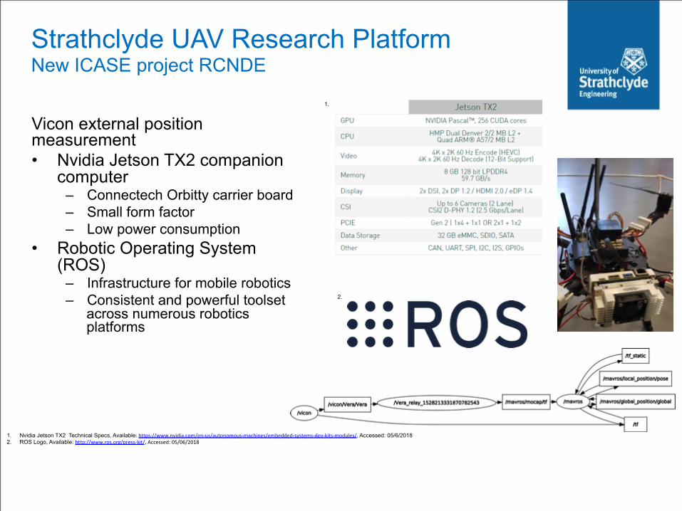
Vicon external position measurement • Nvidia Jetson TX2 companion
computer – Connectech Orbitty carrier board – Small form factor – Low power consumption
• Robotic Operating System (ROS)
– Infrastructure for mobile robotics – Consistent and powerful toolset
across numerous robotics platforms
1.
1. Nvidia Jetson TX2 Technical Specs, Available:https://www.nvidia.com/en-us/autonomous-machines/embedded-systems-dev-kits-modules/,Accessed: 05/6/2018 2. ROS Logo, Available: http://www.ros.org/press-kit/,Accessed:05/06/2018
2.
Strathclyde UAV Research Platform New ICASE project RCNDE
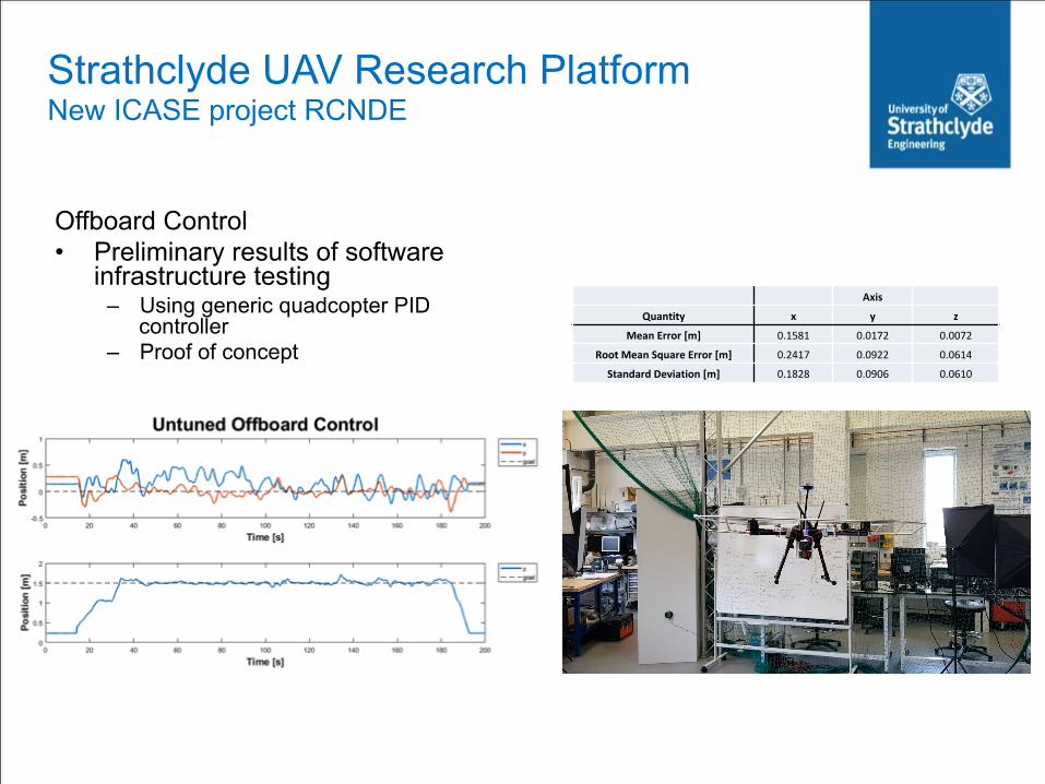
Axis
Quantity x y z
MeanError[m] 0.1581 0.0172 0.0072
RootMeanSquareError[m] 0.2417 0.0922 0.0614
StandardDeviation[m] 0.1828 0.0906 0.0610
Offboard Control • Preliminary results of software
infrastructure testing – Using generic quadcopter PID
controller – Proof of concept
Strathclyde UAV Research Platform New ICASE project RCNDE

Next Steps New sensors and control
• Vicon accuracy study – Comparative assessment
with Leica tracker ground truth – improve accuracy of lab measurements
• Offboard control – Tune controller – Implement ROS node for
arbitrary complex paths • Ultrasound from a UAV
– Mount wheel probe – Scan planar structures – Move to complex geometries
• Whisking sensors – Contact based – Collaboration with Bristol
Robotics Lab • Real Time Kinematic GPS
– Integration and assessment
1. Here+RTKGPSKIt,Available:https://cdn8.bigcommerce.com/s-xkoep7/images/stencil/1280x1280/products/1300/7573/Here___80503.1501686285.jpg?c=2&imbypass=on,Accessed:10/01/2018
1.

• The Structural Dynamics Laboratory for Verification and Validation (LVV) is a major new acoustics and vibration testing facility funded by EPSRC, the European Regional Development Fund (ERDF) and the University of Sheffield.
• The facility provides a unique research offering to academia and industry. In addition to allowing dynamic testing of full-scale structures in ambient laboratory conditions, the LVV offers the opportunity to test substantial structures, sub-structures and components in realistic environments.
• LVV will allow full environmental testing of new autonomous systems and control approaches developed through EPSRC funded AIMaReM project.
The LVV comprises of: Three large, individual climatic test rooms allowing simulation of temperature, humidity, wind and rainfall effects. One room contains a 3.2m x 2.2m integrated Multi Axis Shaker Table (MAST). Further electrodynamic vibration systems allow a flexible range of testing to be conducted both within and outside the climatic test rooms. A precision glass-sided wave tank with double flap wave generator (12m long, 1.5m deep) enabling simulation of deep water conditions. A strong floor (16m long x 3.5m wide) and wall (3m tall x 3.5m wide) enabling the testing of large components and structures in a range of mounting configurations. Flexible laboratory space suitable for a broad range of dynamic testing at ambient temperatures (approx. 12m x 12m).
NewLVVLaboratorylocatedatSheffieldBusinessParknexttoFactory2050
Next Steps Environmental performance evaluation

• Robot path planning and control – Pre-planned flight paths – Laser ranging/ scanner in flight control – ROS platform integration
• Surface geometry measurement – Using visual data and photogrammetry reconstruction (bith commercial tools and
research approaches) • 3D high precision positioning
– Calibrated 3D metrology capabilities – allows new control algorithms to be evaluated – LVV facility at Sheffield for environmental performance validation
• Novel sensors & data processing – Automated defect and object recognition – Ultrasonic sensors – Contact sensors (whisking etc)
Conclusions Many opportunities for collaboration
CentreforUltrasonicEngineering