avid unity media engine and avid mediarray xt setup...
TRANSCRIPT
m a k e m a n a g e m ove | m e d i a ™ Avid ®
Avid Unity™ Media Engineand Avid MEDIArray™ XT
Setup Guide

2
Copyright and DisclaimerProduct specifications are subject to change without notice and do not represent a commitment on the part of Avid Technology, Inc.
The software described in this document is furnished under a license agreement. You can obtain a copy of that license by visiting Avid's Web site at www.avid.com. The terms of that license are also available in the product in the same directory as the software. The software may not be reverse assembled and may be used or copied only in accordance with the terms of the license agreement. It is against the law to copy the software on any medium except as specifically allowed in the license agreement.
Avid products or portions thereof are protected by one or more of the following United States Patents: 4,746,994; 4,970,663; 5,045,940; 5,267,351; 5,309,528; 5,355,450; 5,396,594; 5,440,348; 5,452,378; 5,467,288; 5,513,375; 5,528,310; 5,557,423; 5,577,190; 5,584,006; 5,640,601; 5,644,364; 5,654,737; 5,715,018; 5,724,605; 5,726,717; 5,729,673; 5,745,637; 5,752,029; 5,754,851; 5,799,150; 5,812,216; 5,828,678; 5,842,014; 5,852,435; 5,987,501; 6,061,758; 6,223,211; 6,301,105; 6,532,043; 6,546,190; 6,636,869; 6,747,705, 6,763,523; 6,813,622. Other patents are pending.
This document is protected under copyright law. An authorized licensee of Avid Unity MediaNetwork may reproduce this publication for the licensee’s own use in learning how to use the software. This document may not be reproduced or distributed, in whole or in part, for commercial purposes, such as selling copies of this document or providing support or educational services to others. This document is supplied as a guide for Avid Unity MediaNetwork. Reasonable care has been taken in preparing the information it contains. However, this document may contain omissions, technical inaccuracies, or typographical errors. Avid Technology, Inc. does not accept responsibility of any kind for customers’ losses due to the use of this document. Product specifications are subject to change without notice.
Copyright © 2007 Avid Technology, Inc. and its licensors. All rights reserved. Part of the software embedded in this product is gSOAP software.
Portions created by gSOAP are Copyright (C) 2001-2004 Robert A. van Engelen, Genivia inc. All Rights Reserved.
THE SOFTWARE IN THIS PRODUCT WAS IN PART PROVIDED BY GENIVIA INC AND ANY EXPRESS OR IMPLIED WARRANTIES, INCLUDING, BUT NOT LIMITED TO, THE IMPLIED WARRANTIES OF MERCHANTABILITY AND FITNESS FOR A PARTICULAR PURPOSE ARE DISCLAIMED. IN NO EVENT SHALL THE AUTHOR BE LIABLE FOR ANY DIRECT, INDIRECT, INCIDENTAL, SPECIAL, EXEMPLARY, OR CONSEQUENTIAL DAMAGES (INCLUDING, BUT NOT LIMITED TO, PROCUREMENT OF SUBSTITUTE GOODS OR SERVICES; LOSS OF USE, DATA, OR PROFITS; OR BUSINESS INTERRUPTION) HOWEVER CAUSED AND ON ANY THEORY OF LIABILITY, WHETHER IN CONTRACT, STRICT LIABILITY, OR TORT (INCLUDING NEGLIGENCE OR OTHERWISE) ARISING IN ANY WAY OUT OF THE USE OF THIS SOFTWARE, EVEN IF ADVISED OF THE POSSIBILITY OF SUCH DAMAGE.
The following disclaimer is required by Sam Leffler and Silicon Graphics, Inc. for the use of their TIFF library:Copyright © 1988–1997 Sam Leffler Copyright © 1991–1997 Silicon Graphics, Inc.
Permission to use, copy, modify, distribute, and sell this software [i.e., the TIFF library] and its documentation for any purpose is hereby granted without fee, provided that (i) the above copyright notices and this permission notice appear in all copies of the software and related documentation, and (ii) the names of Sam Leffler and Silicon Graphics may not be used in any advertising or publicity relating to the software without the specific, prior written permission of Sam Leffler and Silicon Graphics.
THE SOFTWARE IS PROVIDED “AS-IS” AND WITHOUT WARRANTY OF ANY KIND, EXPRESS, IMPLIED OR OTHERWISE, INCLUDING WITHOUT LIMITATION, ANY WARRANTY OF MERCHANTABILITY OR FITNESS FOR A PARTICULAR PURPOSE.
IN NO EVENT SHALL SAM LEFFLER OR SILICON GRAPHICS BE LIABLE FOR ANY SPECIAL, INCIDENTAL, INDIRECT OR CONSEQUENTIAL DAMAGES OF ANY KIND, OR ANY DAMAGES WHATSOEVER RESULTING FROM LOSS OF USE, DATA OR PROFITS, WHETHER OR NOT ADVISED OF THE POSSIBILITY OF DAMAGE, AND ON ANY THEORY OF LIABILITY, ARISING OUT OF OR IN CONNECTION WITH THE USE OR PERFORMANCE OF THIS SOFTWARE.
The following disclaimer is required by the Independent JPEG Group:Portions of this software are based on work of the Independent JPEG Group.
The following disclaimer is required by Paradigm Matrix:Portions of this software licensed from Paradigm Matrix.
The following disclaimer is required by Ray Sauers Associates, Inc.:“Install-It” is licensed from Ray Sauers Associates, Inc. End-User is prohibited from taking any action to derive a source code equivalent of “Install-It,” including by reverse assembly or reverse compilation, Ray Sauers Associates, Inc. shall in no event be

3
liable for any damages resulting from reseller’s failure to perform reseller’s obligation; or any damages arising from use or operation of reseller’s products or the software; or any other damages, including but not limited to, incidental, direct, indirect, special or consequential Damages including lost profits, or damages resulting from loss of use or inability to use reseller’s products or the software for any reason including copyright or patent infringement, or lost data, even if Ray Sauers Associates has been advised, knew or should have known of the possibility of such damages.
The following disclaimer is required by Videomedia, Inc.:“Videomedia, Inc. makes no warranties whatsoever, either express or implied, regarding this product, including warranties with respect to its merchantability or its fitness for any particular purpose.”
“This software contains V-LAN ver. 3.0 Command Protocols which communicate with V-LAN ver. 3.0 products developed by Videomedia, Inc. and V-LAN ver. 3.0 compatible products developed by third parties under license from Videomedia, Inc. Use of this software will allow “frame accurate” editing control of applicable videotape recorder decks, videodisc recorders/players and the like.”
The following disclaimer is required by Altura Software, Inc. for the use of its Mac2Win software and Sample Source Code:©1993–1998 Altura Software, Inc.
The following disclaimer is required by Ultimatte Corporation:Certain real-time compositing capabilities are provided under a license of such technology from Ultimatte Corporation and are subject to copyright protection.
The following disclaimer is required by 3Prong.com Inc.:Certain waveform and vector monitoring capabilities are provided under a license from 3Prong.com Inc.
Attn. Government User(s). Restricted Rights LegendU.S. GOVERNMENT RESTRICTED RIGHTS. This Software and its documentation are “commercial computer software” or “commercial computer software documentation.” In the event that such Software or documentation is acquired by or on behalf of a unit or agency of the U.S. Government, all rights with respect to this Software and documentation are subject to the terms of the License Agreement, pursuant to FAR §12.212(a) and/or DFARS §227.7202-1(a), as applicable.
Trademarks888 I/O, Adrenaline, AirPlay, AirSPACE, AirSPACE HD, AirSpeed, AniMatte, AudioSuite, AudioVision, AutoSync, Avid, Avid DNA, Avid DNxcel, Avid DNxHD, AVIDdrive, AVIDdrive Towers, Avid DS Assist Station, Avid ISIS, Avid Learning Excellerator, Avid Liquid, Avid Mojo, AvidNet, AvidNetwork, Avid Remote Response, AVIDstripe, Avid Unity, Avid Unity ISIS, Avid Xpress, AVoption, AVX, CamCutter, ChromaCurve, ChromaWheel, DAE, Dazzle, Deko, DekoCast, D-Fi, D-fx, DigiDelivery, Digidesign, Digidesign Audio Engine, Digidesign Intelligent Noise Reduction, DigiDrive, Digital Nonlinear Accelerator, DigiTranslator, DINR, DNxchange, do more, D-Verb, Equinox, ExpertRender, Face Robot, FACE ROBOT, FieldPak, Film Composer, FilmScribe, FluidMotion, FXDeko, HIIP, HyperSPACE, HyperSPACE HDCAM, IllusionFX, Image Independence, iNEWS, iNEWS ControlAir, Instinct, Interplay, Intraframe, iS9, iS18, iS23, iS36, IsoSync, LaunchPad, Lightning, Lo-Fi, Magic Mask, make manage move | media, Marquee, Matador, Maxim, MCXpress, Media Browse, Media Composer, MediaDock, MediaDock Shuttle, Media Fusion, Media Illusion, MediaLog, Media Reader, Media Recorder, MEDIArray, MediaShare, MediaStream, Meridien, MetaSync, MissionControl, NaturalMatch, Nearchive, NetReview, NewsCutter, Nitris, OMF, OMF Interchange, OMM, Open Media Framework, Open Media Management, PCTV, Pinnacle MediaSuite, Pinnacle Studio, Pinnacle Systems, ProEncode, Pro Tools, QuietDrive, Recti-Fi, RetroLoop, rS9, rS18, Sci-Fi, ScriptSync, SecureProductionEnvironment, Show Center, Softimage, Sound Designer II, SPACE, SPACEShift, SpectraGraph, SpectraMatte, SteadyGlide, Symphony, TARGA, Thunder, Thunder station, Trilligent, UnityRAID, Vari-Fi, Video RAID, Video Slave Driver, VideoSPACE, and Xdeck are either registered trademarks or trademarks of Avid Technology, Inc. in the United States and/or other countries.
3ware is registered trademarks of Applied Micro Circuits Corporation in the United States. Acrobat and Adobe are registered trademarks of Adobe Systems Incorporated in the United States and/or other countries. Adaptec is a trademark of Adaptec, Inc., which may be registered in some jurisdictions. Alacritech is a registered trademark of Alacritech, Inc. Asanté is a registered trademark of Asanté Technologies, Inc. ATTO is a trademark of ATTO Technology, Inc. DAVE is a registered trademark of Thursby Software Systems, Inc. FireWire is a registered trademarks of Apple Computer, Inc., registered in the U.S. and other countries. Ghost is a registered trademark of Symantec Corporation in the United States and other countries. Macintosh is a trademark of Apple Computer, Inc., registered in the U.S. and other countries. QLogic is a registered trademark of QLogic. MS-DOS, Windows, Windows Media, and Windows NT are either registered trademarks or trademarks of Microsoft Corporation in the United States and/or other countries. All other trademarks contained herein are the property of their respective owners.

4
GOT FOOTAGE?
Editors — Filmmakers — Special Effects Artists — Game Developers — Animators — Educators — Broadcasters — Content creators of every genre — Just finished an incredible project and want to share it with the world?
Send us your reels and we may use your footage in our show reel or demo!*
For a copy of our release and Avid’s mailing address, go to www.avid.com/footage.
*Note: Avid cannot guarantee the use of materials submitted.
Avid Unity Media Engine and Avid MEDIArray XT Setup Guide • 0130-07814-01 • July 2007
Contents
Using This Guide . . . . . . . . . . . . . . . . . . . . . . . . . . . . . . . . . . . . . . . . . . . . 13
Symbols and Conventions . . . . . . . . . . . . . . . . . . . . . . . . . . . . . . . . . . . . . . . . . . . . 13
If You Need Help. . . . . . . . . . . . . . . . . . . . . . . . . . . . . . . . . . . . . . . . . . . . . . . . . . . . 14
How to Order Documentation . . . . . . . . . . . . . . . . . . . . . . . . . . . . . . . . . . . . . . . . . . 14
Avid Educational Services. . . . . . . . . . . . . . . . . . . . . . . . . . . . . . . . . . . . . . . . . . . . . 14
Chapter 1 Media Engine and MEDIArray XT Overview. . . . . . . . . . . . . . . . . . . . . . . 15
Media Engine and MEDIArray XT Hardware . . . . . . . . . . . . . . . . . . . . . . . . . . . . . . 15
Media Engine and MEDIArray XT Front Panel. . . . . . . . . . . . . . . . . . . . . . . . . . 16
Media Engine and MEDIArray XT Rear Panel . . . . . . . . . . . . . . . . . . . . . . . . . . 17
Avid Unity Media Engine Networks . . . . . . . . . . . . . . . . . . . . . . . . . . . . . . . . . . . . . . 18
Operating Systems . . . . . . . . . . . . . . . . . . . . . . . . . . . . . . . . . . . . . . . . . . . . . . . . . . 20
Installation Prerequisites . . . . . . . . . . . . . . . . . . . . . . . . . . . . . . . . . . . . . . . . . . . . . . 21
Chapter 2 Installing a Avid Unity Media Engine . . . . . . . . . . . . . . . . . . . . . . . . . . . . 23
Installing the Avid Unity Media Engine Hardware . . . . . . . . . . . . . . . . . . . . . . . . . . . 23
Standard Components . . . . . . . . . . . . . . . . . . . . . . . . . . . . . . . . . . . . . . . . . . . . 24
Optional Components. . . . . . . . . . . . . . . . . . . . . . . . . . . . . . . . . . . . . . . . . . . . . 24
Installing Additional Adapter Boards . . . . . . . . . . . . . . . . . . . . . . . . . . . . . . . . . 24
Installing Avid Unity Media Engine in a Rack . . . . . . . . . . . . . . . . . . . . . . . . . . . . . . 25
Checking the Contents of the Rack-Mount Kit . . . . . . . . . . . . . . . . . . . . . . . . . . 26
Positioning the Avid Unity Media Engine in the Rack. . . . . . . . . . . . . . . . . . . . . 27
Separating the Slide Rails . . . . . . . . . . . . . . . . . . . . . . . . . . . . . . . . . . . . . . . . . 28
Attaching the Rear Bracket . . . . . . . . . . . . . . . . . . . . . . . . . . . . . . . . . . . . . . . . 29
Attaching the Outer Rails to the Rack . . . . . . . . . . . . . . . . . . . . . . . . . . . . . . . . 30
Attaching Inner Slide Rails to the Avid Unity Media Engine . . . . . . . . . . . . . . . . 33
Securing the Avid Unity Media Engine in a Rack . . . . . . . . . . . . . . . . . . . . . . . . 34
Installing the Avid Unity Media Engine Drives. . . . . . . . . . . . . . . . . . . . . . . . . . . . . . 34
Configuring Considerations. . . . . . . . . . . . . . . . . . . . . . . . . . . . . . . . . . . . . . . . . . . . 35
6
Installing the Application Key . . . . . . . . . . . . . . . . . . . . . . . . . . . . . . . . . . . . . . . . . . 37
Connecting a Keyboard, Monitor, and Mouse . . . . . . . . . . . . . . . . . . . . . . . . . . . . . 37
Connecting Power Cords . . . . . . . . . . . . . . . . . . . . . . . . . . . . . . . . . . . . . . . . . . . . . 38
Connecting the Ethernet Switch . . . . . . . . . . . . . . . . . . . . . . . . . . . . . . . . . . . . . . . . 38
Connecting the Fibre Channel Switch . . . . . . . . . . . . . . . . . . . . . . . . . . . . . . . . . . . 40
Connecting the Media Engine to the Fibre Channel Switch . . . . . . . . . . . . . . . 41
Connecting the Media Engine with Two MEDIASwitch 16-4Gbs . . . . . . . . . . . 41
Loading the MEDIASwitch License Configuration. . . . . . . . . . . . . . . . . . . . . . . 43
Loading the MEDIASwitch Configuration . . . . . . . . . . . . . . . . . . . . . . . . . . . . . 45
Connecting a Avid MEDIArray XT Drive Enclosure . . . . . . . . . . . . . . . . . . . . . . . . . 47
Connecting Multiple Avid MEDIArray XT Enclosures to a MEDIASwitch . . . . . 48
Connecting Multiple Avid MEDIArray XT Enclosures to Two MEDIASwitches . 49
Connecting a Workgroup to an In-House Network. . . . . . . . . . . . . . . . . . . . . . . . . . 50
Turning On the Media Engine or Avid MEDIArray XT Hardware . . . . . . . . . . . . . . . 50
Configuring the Media Engine or Avid MEDIArray XT Using Windows Setup . . . . . 51
Chapter 3 Configuring the Avid Unity Media Engine . . . . . . . . . . . . . . . . . . . . . . . . 53
Windows Operating System and Network Settings . . . . . . . . . . . . . . . . . . . . . . . . . 53
Setting the Date, Time, and Time Zone. . . . . . . . . . . . . . . . . . . . . . . . . . . . . . . 54
Specifying a Unique Computer Name . . . . . . . . . . . . . . . . . . . . . . . . . . . . . . . . 54
IP Addressing Strategies When Connecting to a Network . . . . . . . . . . . . . . . . 55
Configuring the Media Engine Network Properties . . . . . . . . . . . . . . . . . . . . . . 55
Installing the Media Engine and Avid MEDIArray XT Software . . . . . . . . . . . . . . . . 56
Setting the Virtual File Manager Name . . . . . . . . . . . . . . . . . . . . . . . . . . . . . . . . . . 57
Configuring the MediaNetwork Software . . . . . . . . . . . . . . . . . . . . . . . . . . . . . . . . . 57
Creating a Drive Set . . . . . . . . . . . . . . . . . . . . . . . . . . . . . . . . . . . . . . . . . . . . . 58
Creating an Allocation Group . . . . . . . . . . . . . . . . . . . . . . . . . . . . . . . . . . . . . . 58
Creating Workspaces . . . . . . . . . . . . . . . . . . . . . . . . . . . . . . . . . . . . . . . . . . . . 59
Creating User Accounts . . . . . . . . . . . . . . . . . . . . . . . . . . . . . . . . . . . . . . . . . . 60
Mounting Workspaces . . . . . . . . . . . . . . . . . . . . . . . . . . . . . . . . . . . . . . . . . . . . . . . 60
Sharing MediaNetwork Workspaces . . . . . . . . . . . . . . . . . . . . . . . . . . . . . . . . . . . . 61
Allowing Network Installation of Ethernet Client Software . . . . . . . . . . . . . . . . . . . . 62
Connecting Avid Unity MediaNetwork Clients . . . . . . . . . . . . . . . . . . . . . . . . . . . . . 62
7
Chapter 4 Troubleshooting . . . . . . . . . . . . . . . . . . . . . . . . . . . . . . . . . . . . . . . . . . . . . 63
Ping and Tracert Commands . . . . . . . . . . . . . . . . . . . . . . . . . . . . . . . . . . . . . . . . . . 63
Ping . . . . . . . . . . . . . . . . . . . . . . . . . . . . . . . . . . . . . . . . . . . . . . . . . . . . . . . . . . 63
Tracert . . . . . . . . . . . . . . . . . . . . . . . . . . . . . . . . . . . . . . . . . . . . . . . . . . . . . . . . 65
Media Engine or Avid MEDIArray XT Is Whistling . . . . . . . . . . . . . . . . . . . . . . . . . . 66
Checking the Operating System . . . . . . . . . . . . . . . . . . . . . . . . . . . . . . . . . . . . . . . . 66
Removing and Replacing Drives. . . . . . . . . . . . . . . . . . . . . . . . . . . . . . . . . . . . . . . . 67
Removing a Drive. . . . . . . . . . . . . . . . . . . . . . . . . . . . . . . . . . . . . . . . . . . . . . . . 67
Replacing a Drive . . . . . . . . . . . . . . . . . . . . . . . . . . . . . . . . . . . . . . . . . . . . . . . . 68
Troubleshooting a Workgroup. . . . . . . . . . . . . . . . . . . . . . . . . . . . . . . . . . . . . . . . . . 68
Understanding Disk Error Logging and the DEAN Light . . . . . . . . . . . . . . . . . . 68
Avid Editing Application Performance Issues. . . . . . . . . . . . . . . . . . . . . . . . . . . 70
Workspaces Are Not Available to an Ethernet Client . . . . . . . . . . . . . . . . . . . . . 70
Macintosh Client Cannot Mount Shared Workspaces . . . . . . . . . . . . . . . . . . . . 70
Appendix A Specifications and Notices . . . . . . . . . . . . . . . . . . . . . . . . . . . . . . . . . . . . 71
Dimensions and Weight . . . . . . . . . . . . . . . . . . . . . . . . . . . . . . . . . . . . . . . . . . . . . . 71
Environment . . . . . . . . . . . . . . . . . . . . . . . . . . . . . . . . . . . . . . . . . . . . . . . . . . . . . . . 72
Electrical . . . . . . . . . . . . . . . . . . . . . . . . . . . . . . . . . . . . . . . . . . . . . . . . . . . . . . . . . . 73
Power Cords . . . . . . . . . . . . . . . . . . . . . . . . . . . . . . . . . . . . . . . . . . . . . . . . . . . . . . . 73
Supported Cabling . . . . . . . . . . . . . . . . . . . . . . . . . . . . . . . . . . . . . . . . . . . . . . . . . . 75
Lithium Battery Replacement . . . . . . . . . . . . . . . . . . . . . . . . . . . . . . . . . . . . . . . . . . 76
Appendix B Configuring a DNS Server . . . . . . . . . . . . . . . . . . . . . . . . . . . . . . . . . . . . . 77
Understanding DNS . . . . . . . . . . . . . . . . . . . . . . . . . . . . . . . . . . . . . . . . . . . . . . . . . 77
IP Addressing . . . . . . . . . . . . . . . . . . . . . . . . . . . . . . . . . . . . . . . . . . . . . . . . . . . 77
DNS Naming . . . . . . . . . . . . . . . . . . . . . . . . . . . . . . . . . . . . . . . . . . . . . . . . . . . 78
Name Resolution . . . . . . . . . . . . . . . . . . . . . . . . . . . . . . . . . . . . . . . . . . . . . . . . 79
DNS Server Access . . . . . . . . . . . . . . . . . . . . . . . . . . . . . . . . . . . . . . . . . . . . . . 79
DNS Data Distribution . . . . . . . . . . . . . . . . . . . . . . . . . . . . . . . . . . . . . . . . . . . . 80
DNS Referrals . . . . . . . . . . . . . . . . . . . . . . . . . . . . . . . . . . . . . . . . . . . . . . . . . . 80
Top Level DNS Servers . . . . . . . . . . . . . . . . . . . . . . . . . . . . . . . . . . . . . . . . . . . 81
Windows and DNS . . . . . . . . . . . . . . . . . . . . . . . . . . . . . . . . . . . . . . . . . . . . . . . 81
Configuring the DNS Server . . . . . . . . . . . . . . . . . . . . . . . . . . . . . . . . . . . . . . . . . . . 82
Configuring the DNS Console . . . . . . . . . . . . . . . . . . . . . . . . . . . . . . . . . . . . . . . . . . 84

8
Creating a Host Record . . . . . . . . . . . . . . . . . . . . . . . . . . . . . . . . . . . . . . . . . . . . . . 89
Creating an Associated Pointer Record . . . . . . . . . . . . . . . . . . . . . . . . . . . . . . . . . . 91
Configuring the Avid Unity Media Engine for the DNS Server . . . . . . . . . . . . . . . . . 93
Appendix C Using the Product Recovery DVD-ROM . . . . . . . . . . . . . . . . . . . . . . . . . . 95
Reinstalling the Windows Operating System . . . . . . . . . . . . . . . . . . . . . . . . . . . . . . 96
Configuring the Windows Operating System . . . . . . . . . . . . . . . . . . . . . . . . . . . . . . 97
Appendix D Regulatory and Safety Notices . . . . . . . . . . . . . . . . . . . . . . . . . . . . . . . . 101
Warnings and Cautions . . . . . . . . . . . . . . . . . . . . . . . . . . . . . . . . . . . . . . . . . . . . . 101
FCC Notice. . . . . . . . . . . . . . . . . . . . . . . . . . . . . . . . . . . . . . . . . . . . . . . . . . . . . . . 101
Canadian ICES-003 . . . . . . . . . . . . . . . . . . . . . . . . . . . . . . . . . . . . . . . . . . . . . . . . 102
European Union Notice . . . . . . . . . . . . . . . . . . . . . . . . . . . . . . . . . . . . . . . . . . . . . 102
Disposal of Waste Equipment by Users in the European Union . . . . . . . . . . . . . . 104
Australia and New Zealand EMC Regulations . . . . . . . . . . . . . . . . . . . . . . . . . . . . 104
Taiwan EMC Regulations. . . . . . . . . . . . . . . . . . . . . . . . . . . . . . . . . . . . . . . . . . . . 105
Index . . . . . . . . . . . . . . . . . . . . . . . . . . . . . . . . . . . . . . . . . . . . . . . . . . . . . 107
9
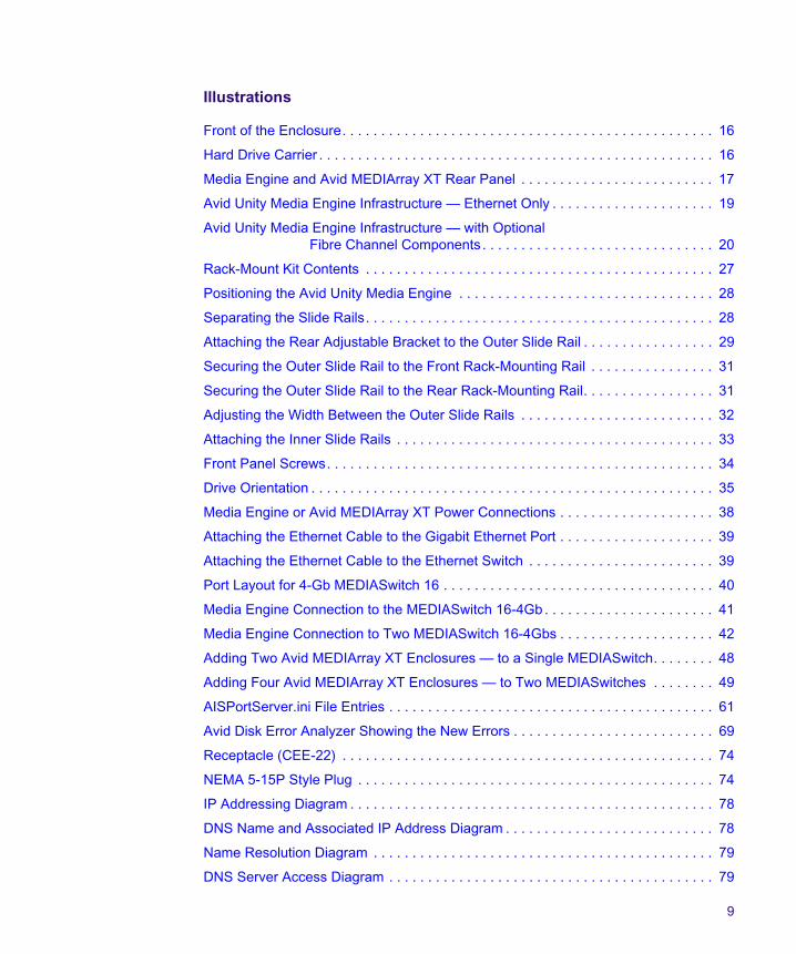
Illustrations
Front of the Enclosure. . . . . . . . . . . . . . . . . . . . . . . . . . . . . . . . . . . . . . . . . . . . . . . . 16
Hard Drive Carrier . . . . . . . . . . . . . . . . . . . . . . . . . . . . . . . . . . . . . . . . . . . . . . . . . . . 16
Media Engine and Avid MEDIArray XT Rear Panel . . . . . . . . . . . . . . . . . . . . . . . . . 17
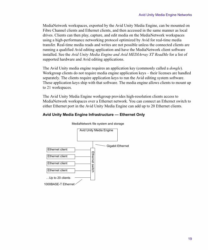
Avid Unity Media Engine Infrastructure — Ethernet Only . . . . . . . . . . . . . . . . . . . . . 19
Avid Unity Media Engine Infrastructure — with Optional Fibre Channel Components . . . . . . . . . . . . . . . . . . . . . . . . . . . . . . 20
Rack-Mount Kit Contents . . . . . . . . . . . . . . . . . . . . . . . . . . . . . . . . . . . . . . . . . . . . . 27
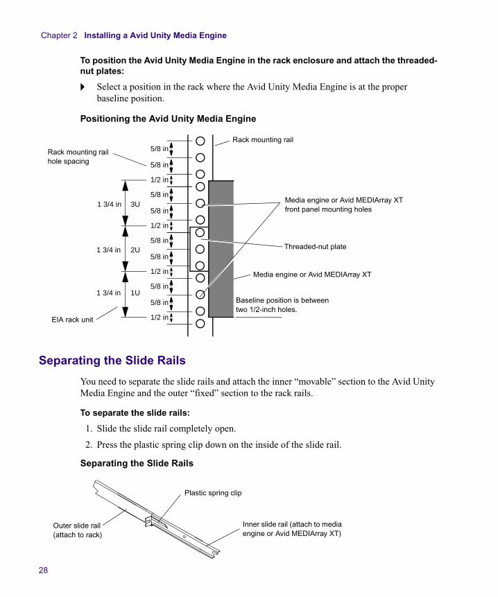
Positioning the Avid Unity Media Engine . . . . . . . . . . . . . . . . . . . . . . . . . . . . . . . . . 28
Separating the Slide Rails. . . . . . . . . . . . . . . . . . . . . . . . . . . . . . . . . . . . . . . . . . . . . 28
Attaching the Rear Adjustable Bracket to the Outer Slide Rail . . . . . . . . . . . . . . . . . 29
Securing the Outer Slide Rail to the Front Rack-Mounting Rail . . . . . . . . . . . . . . . . 31
Securing the Outer Slide Rail to the Rear Rack-Mounting Rail. . . . . . . . . . . . . . . . . 31
Adjusting the Width Between the Outer Slide Rails . . . . . . . . . . . . . . . . . . . . . . . . . 32
Attaching the Inner Slide Rails . . . . . . . . . . . . . . . . . . . . . . . . . . . . . . . . . . . . . . . . . 33
Front Panel Screws. . . . . . . . . . . . . . . . . . . . . . . . . . . . . . . . . . . . . . . . . . . . . . . . . . 34
Drive Orientation . . . . . . . . . . . . . . . . . . . . . . . . . . . . . . . . . . . . . . . . . . . . . . . . . . . . 35
Media Engine or Avid MEDIArray XT Power Connections . . . . . . . . . . . . . . . . . . . . 38
Attaching the Ethernet Cable to the Gigabit Ethernet Port . . . . . . . . . . . . . . . . . . . . 39
Attaching the Ethernet Cable to the Ethernet Switch . . . . . . . . . . . . . . . . . . . . . . . . 39
Port Layout for 4-Gb MEDIASwitch 16 . . . . . . . . . . . . . . . . . . . . . . . . . . . . . . . . . . . 40
Media Engine Connection to the MEDIASwitch 16-4Gb . . . . . . . . . . . . . . . . . . . . . . 41
Media Engine Connection to Two MEDIASwitch 16-4Gbs . . . . . . . . . . . . . . . . . . . . 42
Adding Two Avid MEDIArray XT Enclosures — to a Single MEDIASwitch. . . . . . . . 48
Adding Four Avid MEDIArray XT Enclosures — to Two MEDIASwitches . . . . . . . . 49
AISPortServer.ini File Entries . . . . . . . . . . . . . . . . . . . . . . . . . . . . . . . . . . . . . . . . . . 61
Avid Disk Error Analyzer Showing the New Errors . . . . . . . . . . . . . . . . . . . . . . . . . . 69
Receptacle (CEE-22) . . . . . . . . . . . . . . . . . . . . . . . . . . . . . . . . . . . . . . . . . . . . . . . . 74
NEMA 5-15P Style Plug . . . . . . . . . . . . . . . . . . . . . . . . . . . . . . . . . . . . . . . . . . . . . . 74
IP Addressing Diagram . . . . . . . . . . . . . . . . . . . . . . . . . . . . . . . . . . . . . . . . . . . . . . . 78
DNS Name and Associated IP Address Diagram . . . . . . . . . . . . . . . . . . . . . . . . . . . 78
Name Resolution Diagram . . . . . . . . . . . . . . . . . . . . . . . . . . . . . . . . . . . . . . . . . . . . 79
DNS Server Access Diagram . . . . . . . . . . . . . . . . . . . . . . . . . . . . . . . . . . . . . . . . . . 79

10
DNS Data Distribution Diagram . . . . . . . . . . . . . . . . . . . . . . . . . . . . . . . . . . . . . . . . . 80
DNS Referral Diagram . . . . . . . . . . . . . . . . . . . . . . . . . . . . . . . . . . . . . . . . . . . . . . . . 80
Top Level DNS Server Diagram. . . . . . . . . . . . . . . . . . . . . . . . . . . . . . . . . . . . . . . . . 81
Domain Controller Diagram . . . . . . . . . . . . . . . . . . . . . . . . . . . . . . . . . . . . . . . . . . . . 82
11
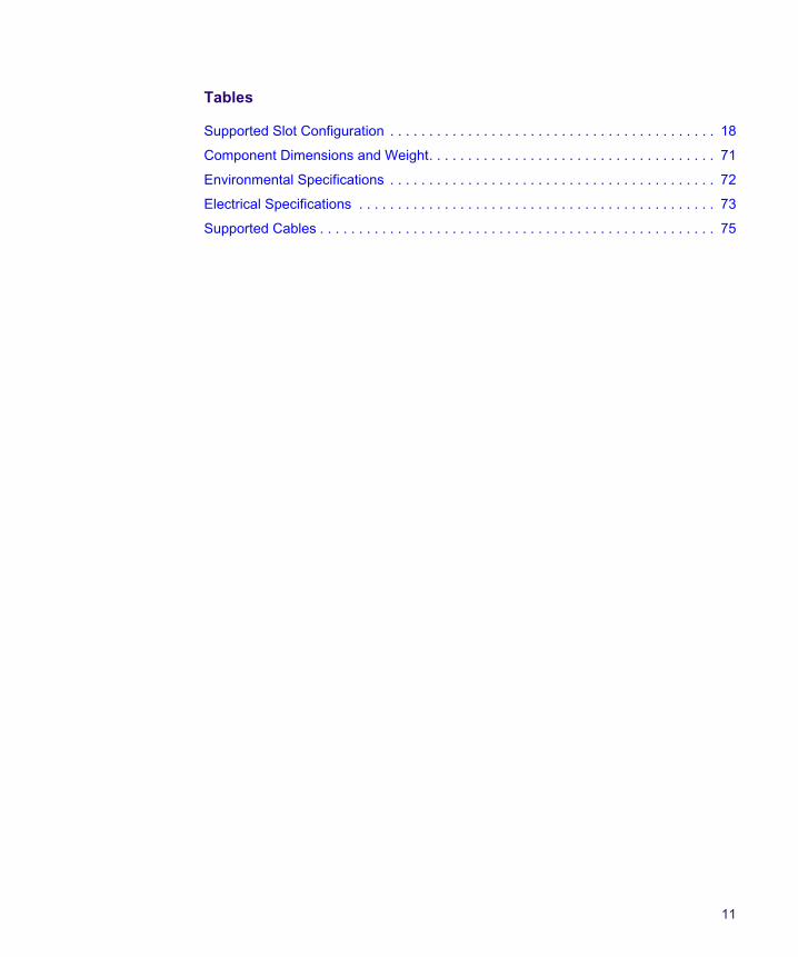
Tables
Supported Slot Configuration . . . . . . . . . . . . . . . . . . . . . . . . . . . . . . . . . . . . . . . . . . 18
Component Dimensions and Weight. . . . . . . . . . . . . . . . . . . . . . . . . . . . . . . . . . . . . 71
Environmental Specifications . . . . . . . . . . . . . . . . . . . . . . . . . . . . . . . . . . . . . . . . . . 72
Electrical Specifications . . . . . . . . . . . . . . . . . . . . . . . . . . . . . . . . . . . . . . . . . . . . . . 73
Supported Cables . . . . . . . . . . . . . . . . . . . . . . . . . . . . . . . . . . . . . . . . . . . . . . . . . . . 75

12
Using This Guide
Congratulations on your purchase of an Avid Unity™ Media Engine or Avid MEDIArray™ XT. The media engine allows you to connect offline, online, low-resolution, or high-resolution Avid® workstations either Ethernet clients and Fibre Channel clients. This allows you to share media files stored on the media engine or on Avid MEDIArray XT storage enclosures.
This guide is intended for administrators and technical personnels who is installing, configuring, and maintaining a media engine and Avid MEDIArray XT storage enclosures. This guide also provides installation and configuration information for the hardware and software.
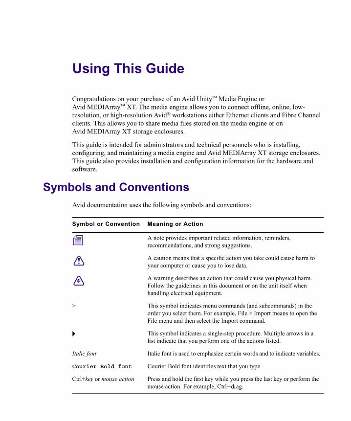
Symbols and ConventionsAvid documentation uses the following symbols and conventions:
Symbol or Convention Meaning or Action
n A note provides important related information, reminders, recommendations, and strong suggestions.
c A caution means that a specific action you take could cause harm to your computer or cause you to lose data.
w A warning describes an action that could cause you physical harm. Follow the guidelines in this document or on the unit itself when handling electrical equipment.
> This symbol indicates menu commands (and subcommands) in the order you select them. For example, File > Import means to open the File menu and then select the Import command.
t This symbol indicates a single-step procedure. Multiple arrows in a list indicate that you perform one of the actions listed.
Italic font Italic font is used to emphasize certain words and to indicate variables.
Courier Bold font Courier Bold font identifies text that you type.
Ctrl+key or mouse action Press and hold the first key while you press the last key or perform the mouse action. For example, Ctrl+drag.
Using This Guide
14
If You Need Help
If you are having trouble using media engine or Avid MEDIArray XT:
1. Retry the action, carefully following the instructions given for that task in this guide. It is especially important to check each step of your workflow.
2. Check for the latest information that might have become available after the documentation was published:
- If the latest information for your Avid product is provided as printed release notes, they ship with your application and are also available online.
- If the latest information for your Avid product is provided as a ReadMe file, it is supplied in your Avid application folder as a PDF document (ReadMe.pdf) and is also available online.
You should always check online for the most up-to-date release notes or ReadMe because the online version is updated whenever new information becomes available. To view these online versions, select ReadMe from the Help menu. or visit the Knowledge Base at www.avid.com/readme.
3. Check the documentation that came with your Avid application or your hardware for maintenance or hardware-related issues.
4. Visit the online Knowledge Base at www.avid.com/onlinesupport. Online services are available 24 hours per day, 7 days per week. Search this online Knowledge Base to find answers, to view error messages, to access troubleshooting tips, to download updates, and to read or join online message-board discussions.
How to Order Documentation
To order additional copies of this documentation from within the United States, call Avid Sales at 800-949-AVID (800-949-2843). If you are placing an order from outside the United States, contact your local Avid representative.
Avid Educational Services
For information on courses/schedules, training centers, certifications, courseware, and books, please visit www.avid.com/training or call Avid Sales at 800-949-AVID (800-949-2843).
Chapter 1
Media Engine and MEDIArray XT Overview
This chapter introduces the Avid Unity Media Engine and Avid MEDIArray XT. The media engine is the next generation of Avid Unity MediaNetwork with higher performance at a lower cost. You can expand this network to connect up to 20 Ethernet clients, and up to 26 Fibre Channel clients. The media engine allows you to add four MEDIArray XT storage enclosures to expand your storage capacity to a 40 terabytes (TB).
Topics in this chapter include:
• Media Engine and MEDIArray XT Hardware
• Avid Unity Media Engine Networks
• Operating Systems
• Installation Prerequisites
Media Engine and MEDIArray XT Hardware
The media engine is a standalone system that runs the Avid Unity MediaNetwork software. It is a dual-processor, rack-mount Windows® computer that contains sixteen 250 GB or 500 GB drives for storing data. The size of the drive is shown on the front of each drive. As newer technology is released, other drive capacities might be supported.
n The Windows Product Key Certificate of Authenticity is initially included in the shipping carton and must be attached to the side of the product.
Chapter 1 Media Engine and MEDIArray XT Overview
16
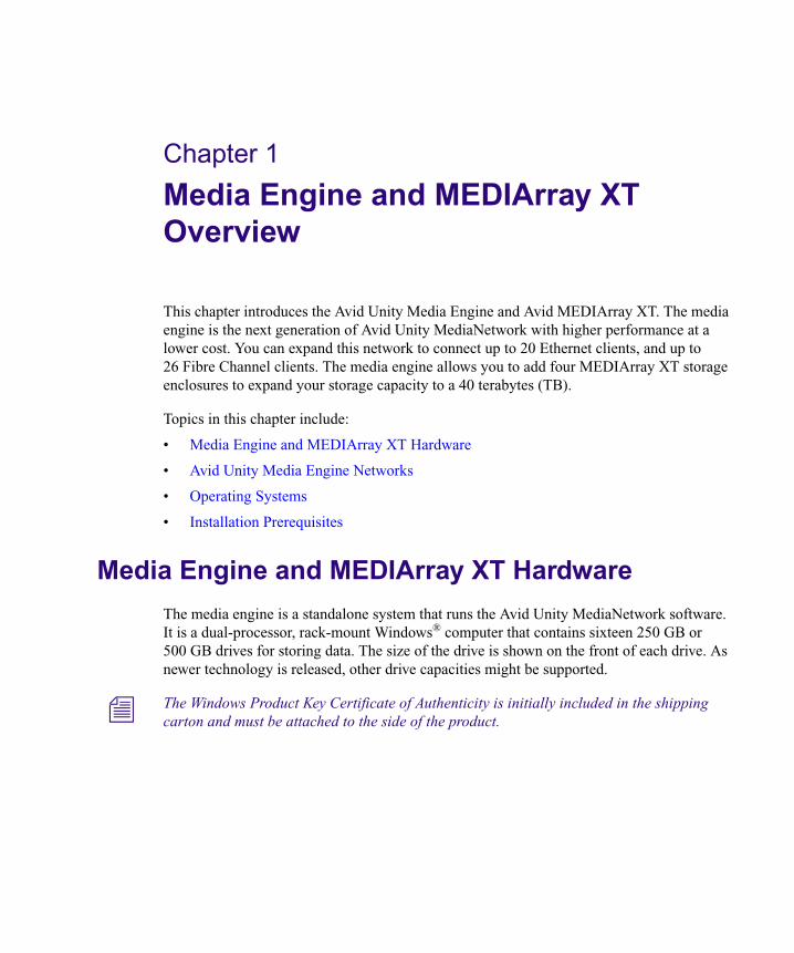
Media Engine and MEDIArray XT Front Panel
The front of the media engine and MEDIArray XT provides access to hard drives, the DVD-ROM drive, and the Power and Reset buttons.
Front of the Enclosure
Each of the hard drives have blue LEDs on the right side of the drive carrier. The top LED is on when a drive has power. The Activity LED flashes when a drive is in use.
Hard Drive Carrier
Power LED
Network activity LED
Network activity LED
Internal drive activity LED
Reset button
Power button
USB connectors
Hard drives
DVD-ROM drive
Power LED
Activity LED
Drive carrier latch
Media Engine and MEDIArray XT Hardware
17
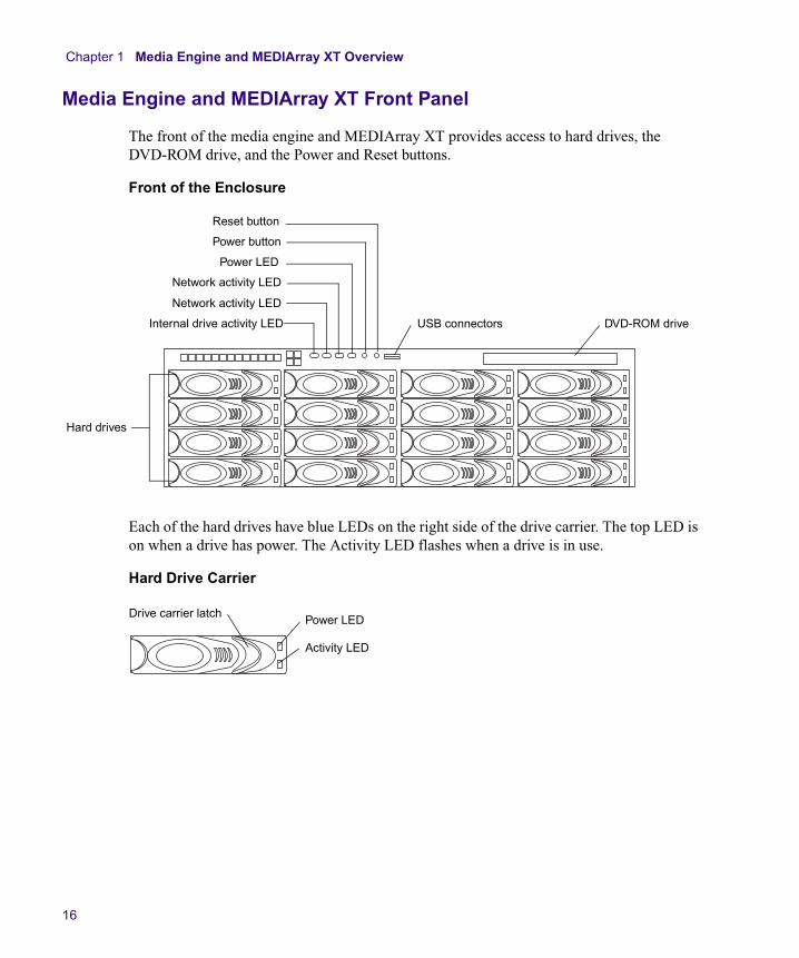
Media Engine and MEDIArray XT Rear Panel
The media engine and Avid MEDIArray XT rear panel contains the power supply modules, the keyboard, mouse, monitor, gigabit Ethernet, Fibre Channel, and USB application key connectors. The Avid Unity Media Engine does not come standard with a Fibre Channel adapter board. Installing a Fibre Channel adapter board provides a Fibre Channel connection in the rear of the chassis.
Media Engine and Avid MEDIArray XT Rear Panel
PCI slots
Serial connector
Power supply modules
VGA monitor connector
Mouse (top)
Keyboard (bottom)
USB connectors 2 Gigabit Ethernet ports
Optional Fibre Channel adapter in the Avid Unity Media EngineAlarm Reset button
7 1
Chapter 1 Media Engine and MEDIArray XT Overview
18
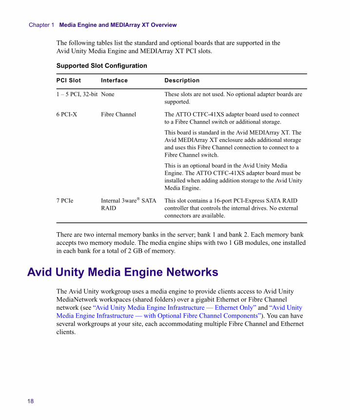
The following tables list the standard and optional boards that are supported in the Avid Unity Media Engine and MEDIArray XT PCI slots.
There are two internal memory banks in the server; bank 1 and bank 2. Each memory bank accepts two memory module. The media engine ships with two 1 GB modules, one installed in each bank for a total of 2 GB of memory.
Avid Unity Media Engine Networks
The Avid Unity workgroup uses a media engine to provide clients access to Avid Unity MediaNetwork workspaces (shared folders) over a gigabit Ethernet or Fibre Channel network (see “Avid Unity Media Engine Infrastructure — Ethernet Only” and “Avid Unity Media Engine Infrastructure — with Optional Fibre Channel Components”). You can have several workgroups at your site, each accommodating multiple Fibre Channel and Ethernet clients.
Supported Slot Configuration
PCI Slot Interface Description
1 – 5 PCI, 32-bit None These slots are not used. No optional adapter boards are supported.
6 PCI-X Fibre Channel The ATTO CTFC-41XS adapter board used to connect to a Fibre Channel switch or additional storage.
This board is standard in the Avid MEDIArray XT. The Avid MEDIArray XT enclosure adds additional storage and uses this Fibre Channel connection to connect to a Fibre Channel switch.
This is an optional board in the Avid Unity Media Engine. The ATTO CTFC-41XS adapter board must be installed when adding addition storage to the Avid Unity Media Engine.
7 PCIe Internal 3ware® SATA RAID
This slot contains a 16-port PCI-Express SATA RAID controller that controls the internal drives. No external connectors are available.
Avid Unity Media Engine Networks
19
MediaNetwork workspaces, exported by the Avid Unity Media Engine, can be mounted on Fibre Channel clients and Ethernet clients, and then accessed in the same manner as local drives. Clients can then play, capture, and edit media on the MediaNetwork workspaces using a high-performance networking protocol optimized by Avid for real-time media transfer. Real-time media reads and writes are not possible unless the connected clients are running a qualified Avid editing application and have the MediaNetwork client software installed. See the Avid Unity Media Engine and Avid MEDIArray XT ReadMe for a list of supported hardware and Avid editing applications.
The Avid Unity media engine requires an application key (commonly called a dongle). Workgroup clients do not require media engine application keys – their licenses are handled separately. The clients require application keys to run the Avid editing system software. These application keys ship with that software. The media engine allows clients to mount up to 21 workspaces.
The Avid Unity Media Engine workgroup provides high-resolution clients access to MediaNetwork workspaces over a Ethernet network. You can connect an Ethernet switch to either Ethernet port in the Avid Unity Media Engine can add up to 20 Ethernet clients.
Avid Unity Media Engine Infrastructure — Ethernet Only
…Up to 20 clients
1000BASE-T Ethernet
Gigabit Ethernet
MediaNetwork file system and storage
Avid Unity Media Engine
Ethernet sw
itchEthernet client
Ethernet client
Ethernet client
Ethernet client
Chapter 1 Media Engine and MEDIArray XT Overview
20
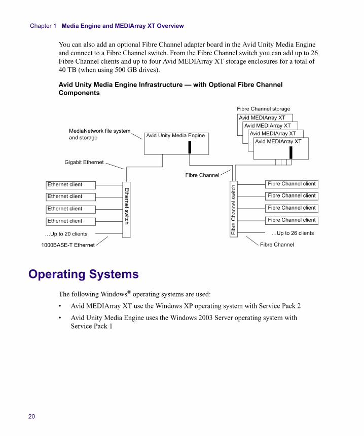
You can also add an optional Fibre Channel adapter board in the Avid Unity Media Engine and connect to a Fibre Channel switch. From the Fibre Channel switch you can add up to 26 Fibre Channel clients and up to four Avid MEDIArray XT storage enclosures for a total of 40 TB (when using 500 GB drives).
Avid Unity Media Engine Infrastructure — with Optional Fibre Channel Components
Operating Systems
The following Windows® operating systems are used:
• Avid MEDIArray XT use the Windows XP operating system with Service Pack 2
• Avid Unity Media Engine uses the Windows 2003 Server operating system with Service Pack 1
…Up to 20 clients
1000BASE-T Ethernet
Gigabit Ethernet
MediaNetwork file system and storage Avid Unity Media Engine
Ethernet sw
itchEthernet client
Ethernet client
Ethernet client
Ethernet client
Fibre Channel storage
Fibre Channel
…Up to 26 clients
Fibre Channel
Fib
re C
hann
el s
witc
h Fibre Channel client
Fibre Channel client
Fibre Channel client
Fibre Channel client
Avid MEDIArray XT
Avid MEDIArray XT
Avid MEDIArray XT
Avid MEDIArray XT
Installation Prerequisites
21
Installation Prerequisites
To set up a Avid Unity workgroup environment you need:
• An Avid Unity Media Engine
• The Avid Unity MediaNetwork software DVD-ROM
• A gigabit Ethernet switch (a nonblocking Gigabit Ethernet-to-10/100/1000BASE-T Ethernet switch) that connects the Avid Unity Media Engine to the Ethernet clients.
Up to 20 Ethernet clients (Avid workstations running a qualified Avid editing system) with 1000BASE-T capable Ethernet connectivity. See the Avid Unity Media Engine and Avid MEDIArray XT ReadMe for information on qualified Ethernet switches.
n Five connections licenses are included with the Avid Unity Media Engine system. See your Avid sales person or your Avid ACSR if you need to purchase more than five clients connection licenses.
• An optional Fibre Channel adapter board and Fibre Channel switch to connect the Avid Unity Media Engine to the Fibre Channel clients.
Up to 26 Fibre Channel clients (Avid workstations running a qualified Avid editing system) with appropriate Fibre Channel connectivity. See the Avid Unity Media Engine and Avid MEDIArray XT ReadMe for information on qualified Fibre Channel switch.
• An optional Avid MEDIArray XT drive enclosure for addition storage. The Avid Unity Media Engine requires an optional Fibre Channel adapter board to connect additional storage.

Chapter 1 Media Engine and MEDIArray XT Overview
22
Chapter 2
Installing a Avid Unity Media Engine
This chapter describes how to install a Avid Unity Media Engine and the Fibre Channel or Ethernet switches to create a workgroup. The workgroup can be standalone or connected to an in-house network.
Topics in this chapter include:
• Installing the Avid Unity Media Engine Hardware
• Installing Avid Unity Media Engine in a Rack
• Installing the Avid Unity Media Engine Drives
• Configuring Considerations
• Installing the Application Key
• Connecting a Keyboard, Monitor, and Mouse
• Connecting Power Cords
• Connecting the Ethernet Switch
• Connecting the Fibre Channel Switch
• Connecting a Avid MEDIArray XT Drive Enclosure
• Connecting a Workgroup to an In-House Network
• Turning On the Media Engine or Avid MEDIArray XT Hardware
• Configuring the Media Engine or Avid MEDIArray XT Using Windows Setup
Installing the Avid Unity Media Engine Hardware
The media engines and the Avid MEDIArray XT ships with two on-board a gigabit Ethernet ports. The Avid MEDIArray XT has a single Fibre Channel controller board is installed. The Fibre Channel board is optional in the Avid Unity Media Engine. For fault-tolerance, the media engine and Avid MEDIArray XT have three autosensing power supply modules that set the voltage automatically for either 120 V or 220 V at 50 to 60 Hz. For detailed specifications, see “Electrical” on page 73.
Chapter 2 Installing a Avid Unity Media Engine
24
n The Windows Product Key Certificate of Authenticity is initially included in the shipping carton and must be attached to the side of the product. Keep the shipping boxes that come with your media engine or Avid MEDIArray XT. You might need to repackage and ship the components in the future.
c The media engine or Avid MEDIArray XT is to be installed only in a restricted access area where only trained and authorized service personnel can have access to them.
Standard Components
The standard media engine and Avid MEDIArray XT components include:
• 16 drives — Each enclosure has sixteen 250 GB or 500 GB externally accessible data drives
• System drive — The media engines use an internal RAID drive set for the operating system and application software, the optional Avid MEDIArray XT uses a single internal drive for the operating system
• Ethernet switch and cables — for the Avid Unity Media Engine clients
• Fiber Channel switch and cables — for the Fibre Channel clients and for the Avid MEDIArray XT
Optional Components
The optional Avid Unity Media Engine components include:
• A standard monitor, keyboard, and mouse
• A keyboard, video, and mouse switch (KVM), if you have multiple rack mounted components
• The Fiber Channel adapter board is optional in the Avid Unity Media Engine for connecting the Avid MEDIArray XT and Fibre Channel clients.
• The Fiber Channel Switch is optional with in the Avid Unity Media Engine, needed to connect the Avid MEDIArray XT and Fibre Channel clients.
All of these components are available from Avid. You can contact Avid Telesales at 800-949-AVID (800-949-2843), your Avid sales representative, or your Avid Reseller to purchase these components.
Installing Additional Adapter Boards
You need to install the optional Fibre Channel adapter board in the Avid Unity Media Engine to attach additional storage (Avid MEDIArray XT) and Fibre Channel clients.
c Additional adapter boards should be installed by Avid trained and authorized service personnel only.
Installing Avid Unity Media Engine in a Rack
25
To install an additional board:
1. Power off the Avid Unity Media Engine and disconnect all three ac power cords in the rear of the enclosure.
2. Remove a cover screw from each side of the Avid Unity Media Engine top cover. The two screws are about 5 inches from the front of the Avid Unity Media Engine; one on each side.
3. Slide the cover back approximately 1 inch.
4. Lift the cover off of the enclosure.
5. Identify the qualified slot for the board you are installing (see “Media Engine and MEDIArray XT Rear Panel” on page 17).
6. Remove the screw holding the slot cover in place.
7. Lift the slot cover out of the enclosure.
n Make sure you are wearing a grounding wrist strap that is attached to the metal of the enclosure before you continue. The boards are sensitive to electrostatic discharge. Do not handle boards unless you are properly grounded.
8. Locate the new board you are installing.
9. Remove the board from the antistatic bag.
10. Insert the board into the slot. Make sure the slot cover aligns correctly.
11. Push the board into the slot. Make sure the board is seated completely in the slot.
12. Replace the slot cover screw to hold the new board in place.
13. Replace the cover.
Installing Avid Unity Media Engine in a Rack
The Avid Unity Media Engine is designed for 19-inch (483-mm) rack enclosures and requires three EIA rack units (3U), or 5.25 inches (133.4 mm) of rack space. The rail kit installs into rails that are between 23 to 31.5 inches deep. Avid Unity Media Engine installs in threaded and non threaded rack enclosures.
The Avid Unity Media Engine ships with slide rails, adjustable brackets, rack-mount screws, and threaded-nut plates. When the inner slide rails are mounted to the Avid Unity Media Engine and the outer slide rails are mounted to the rack, you can secure the Avid Unity Media Engine in the rack so it does not slide forward. If your rack has threaded holes, you might have to supply your own rack fasteners.
Chapter 2 Installing a Avid Unity Media Engine
26
c The Avid Unity Media Engine is designed to be installed horizontally in a rack. Installing the Avid Unity Media Engine on an angle or in a sloped console causes the internal drives to wear faster than the intended life of the drive.
w To ensure the stability of the rack enclosure, start from the bottom when you install the rack components in the rack enclosure.
Rack-mount Requirements:
• Elevated Operating Ambient — If installed in a closed or multi-unit rack assembly, the operating ambient temperature of the rack environment might be greater than room ambient. Therefore, consider installing the equipment in an environment compatible with the maximum ambient temperature (Tma) specified by the manufacturer.
• Reduced Air Flow — Installation of the equipment in a rack should be such that the amount of air flow required for safe operation of the equipment is not compromised.
Avid Unity Media Engine airflow is from the front of the chassis enclosure to the rear. Make allowances for cooling air to be available to the front panel surface and no restrictions at the rear.
• Mechanical Loading — Mounting of the equipment in the rack should be such that a hazardous condition is not achieved due to uneven mechanical loading.
Make sure your rack enclosure is stable enough to prevent tipping over when one or more Avid Unity Media Engine systems are extended on the sliding rails.
• Circuit Overloading — Consideration should be given to the connection of the equipment to the supply circuit and the effect that overloading of the circuits might have on overcurrent protection and supply wiring. Appropriate consideration of equipment nameplate ratings should be used when addressing this concern.
• Reliable Grounding — Reliable grounding of rack-mounted equipment should be maintained. Particular attention should be given to supply connections other than direct connections to the branch circuit (for example, use of power strips).
• Inside Enclosure Access — If you want to extend the chassis, and removed the top cover, you must allow 0.5 in (1.3 cm) clearance on top of the chassis for cover removal.
Checking the Contents of the Rack-Mount Kit
The Avid Unity Media Engine rack-mount kit supplies the hardware for the installing in a wide variety of rack enclosures:
• If your rack has threaded M5 holes, use the M4 x 10 screws and M4 threaded-nut plates.
• If your rack has square holes, use the M5 x 10 screws and M5 threaded-nut plates.
• If your rack has square holes, you can use the hardware included with your rack; such as nuts within a spring-clip assemble.
Installing Avid Unity Media Engine in a Rack
27
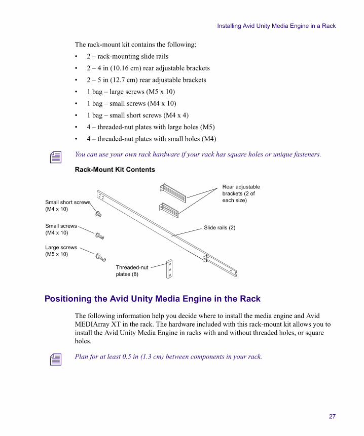
The rack-mount kit contains the following:
• 2 – rack-mounting slide rails
• 2 – 4 in (10.16 cm) rear adjustable brackets
• 2 – 5 in (12.7 cm) rear adjustable brackets
• 1 bag – large screws (M5 x 10)
• 1 bag – small screws (M4 x 10)
• 1 bag – small short screws (M4 x 4)
• 4 – threaded-nut plates with large holes (M5)
• 4 – threaded-nut plates with small holes (M4)
n You can use your own rack hardware if your rack has square holes or unique fasteners.
Rack-Mount Kit Contents
Positioning the Avid Unity Media Engine in the Rack
The following information help you decide where to install the media engine and Avid MEDIArray XT in the rack. The hardware included with this rack-mount kit allows you to install the Avid Unity Media Engine in racks with and without threaded holes, or square holes.
n Plan for at least 0.5 in (1.3 cm) between components in your rack.
Threaded-nut plates (8)
Rear adjustable brackets (2 of each size)
Slide rails (2)
Small short screws (M4 x 10)
Large screws(M5 x 10)
Small screws(M4 x 10)
Chapter 2 Installing a Avid Unity Media Engine
28
To position the Avid Unity Media Engine in the rack enclosure and attach the threaded-nut plates:
t Select a position in the rack where the Avid Unity Media Engine is at the proper baseline position.
Positioning the Avid Unity Media Engine
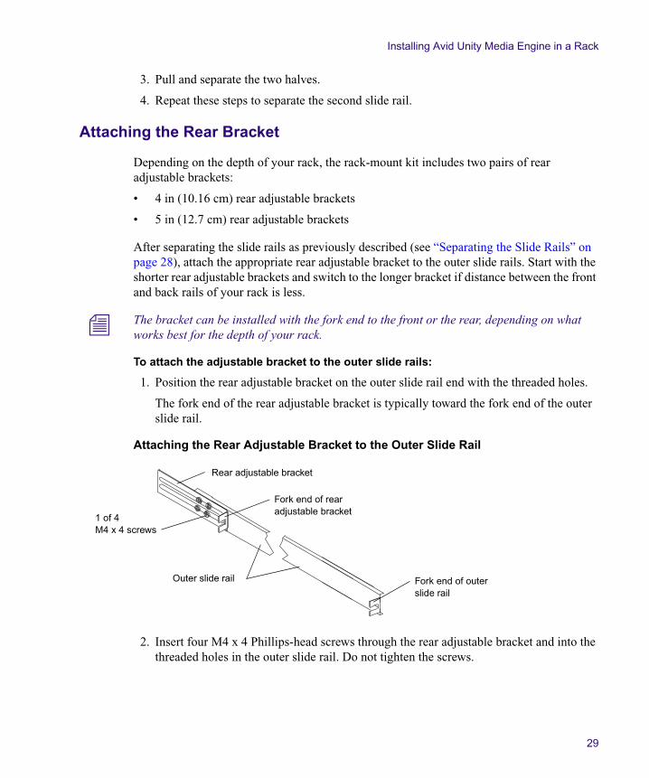
Separating the Slide Rails
You need to separate the slide rails and attach the inner “movable” section to the Avid Unity Media Engine and the outer “fixed” section to the rack rails.
To separate the slide rails:
1. Slide the slide rail completely open.
2. Press the plastic spring clip down on the inside of the slide rail.
Separating the Slide Rails
5/8 in
5/8 in
1/2 in
5/8 in
5/8 in
1/2 in
5/8 in
5/8 in
1/2 in
5/8 in
5/8 in
1/2 in
1U
2U
3U1 3/4 in
1 3/4 in
1 3/4 inBaseline position is between two 1/2-inch holes.
Rack mounting rail hole spacing
EIA rack unit
Rack mounting rail
Media engine or Avid MEDIArray XT
Threaded-nut plate
Media engine or Avid MEDIArray XT front panel mounting holes
Plastic spring clip
Outer slide rail(attach to rack)
Inner slide rail (attach to media engine or Avid MEDIArray XT)
Installing Avid Unity Media Engine in a Rack
29
3. Pull and separate the two halves.
4. Repeat these steps to separate the second slide rail.
Attaching the Rear Bracket
Depending on the depth of your rack, the rack-mount kit includes two pairs of rear adjustable brackets:
• 4 in (10.16 cm) rear adjustable brackets
• 5 in (12.7 cm) rear adjustable brackets
After separating the slide rails as previously described (see “Separating the Slide Rails” on page 28), attach the appropriate rear adjustable bracket to the outer slide rails. Start with the shorter rear adjustable brackets and switch to the longer bracket if distance between the front and back rails of your rack is less.
n The bracket can be installed with the fork end to the front or the rear, depending on what works best for the depth of your rack.
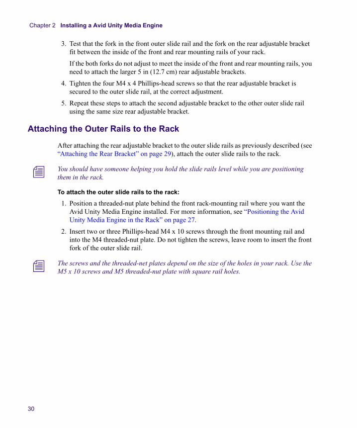
To attach the adjustable bracket to the outer slide rails:
1. Position the rear adjustable bracket on the outer slide rail end with the threaded holes.
The fork end of the rear adjustable bracket is typically toward the fork end of the outer slide rail.
Attaching the Rear Adjustable Bracket to the Outer Slide Rail
2. Insert four M4 x 4 Phillips-head screws through the rear adjustable bracket and into the threaded holes in the outer slide rail. Do not tighten the screws.
Rear adjustable bracket
Outer slide rail
1 of 4 M4 x 4 screws
Fork end of rear adjustable bracket
Fork end of outer slide rail
Chapter 2 Installing a Avid Unity Media Engine
30
3. Test that the fork in the front outer slide rail and the fork on the rear adjustable bracket fit between the inside of the front and rear mounting rails of your rack.
If the both forks do not adjust to meet the inside of the front and rear mounting rails, you need to attach the larger 5 in (12.7 cm) rear adjustable brackets.
4. Tighten the four M4 x 4 Phillips-head screws so that the rear adjustable bracket is secured to the outer slide rail, at the correct adjustment.
5. Repeat these steps to attach the second adjustable bracket to the other outer slide rail using the same size rear adjustable bracket.
Attaching the Outer Rails to the Rack
After attaching the rear adjustable bracket to the outer slide rails as previously described (see “Attaching the Rear Bracket” on page 29), attach the outer slide rails to the rack.
n You should have someone helping you hold the slide rails level while you are positioning them in the rack.
To attach the outer slide rails to the rack:
1. Position a threaded-nut plate behind the front rack-mounting rail where you want the Avid Unity Media Engine installed. For more information, see “Positioning the Avid Unity Media Engine in the Rack” on page 27.
2. Insert two or three Phillips-head M4 x 10 screws through the front mounting rail and into the M4 threaded-nut plate. Do not tighten the screws, leave room to insert the front fork of the outer slide rail.
n The screws and the threaded-net plates depend on the size of the holes in your rack. Use the M5 x 10 screws and M5 threaded-nut plate with square rail holes.
Installing Avid Unity Media Engine in a Rack
31
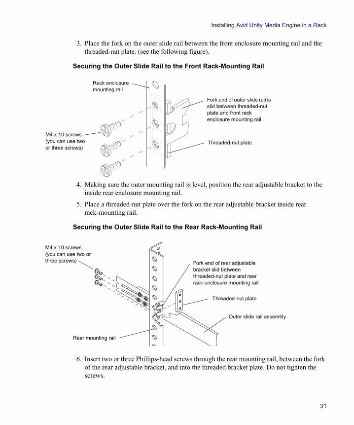
3. Place the fork on the outer slide rail between the front enclosure mounting rail and the threaded-nut plate. (see the following figure).
Securing the Outer Slide Rail to the Front Rack-Mounting Rail
4. Making sure the outer mounting rail is level, position the rear adjustable bracket to the inside rear enclosure mounting rail.
5. Place a threaded-nut plate over the fork on the rear adjustable bracket inside rear rack-mounting rail.
Securing the Outer Slide Rail to the Rear Rack-Mounting Rail
6. Insert two or three Phillips-head screws through the rear mounting rail, between the fork of the rear adjustable bracket, and into the threaded bracket plate. Do not tighten the screws.
Fork end of outer slide rail is slid between threaded-nut plate and front rack enclosure mounting rail
Rack enclosuremounting rail
Threaded-nut plate
M4 x 10 screws (you can use two or three screws)
Rear mounting rail
Outer slide rail assembly
M4 x 10 screws (you can use two or three screws) Fork end of rear adjustable
bracket slid between threaded-nut plate and rear rack enclosure mounting rail
Threaded-nut plate
Chapter 2 Installing a Avid Unity Media Engine
32
n The screws and the threaded-nut plates depend on the size of the holes in your rack. Use the M5 x 10 screws and M5 threaded-nut plate with square rail holes.
7. Repeat this procedure to attach the second outer slide rail on the other side of the rack.
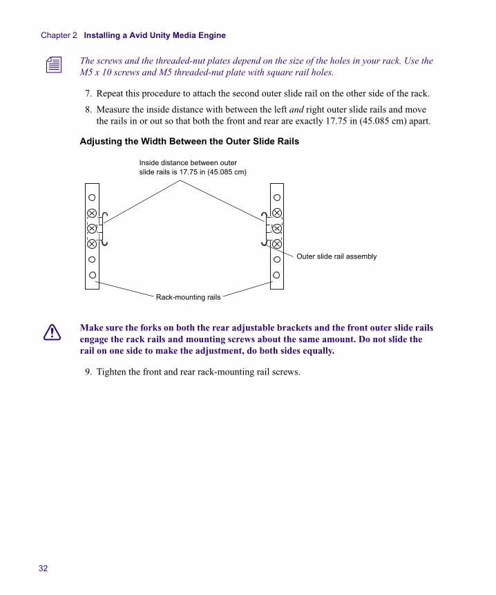
8. Measure the inside distance with between the left and right outer slide rails and move the rails in or out so that both the front and rear are exactly 17.75 in (45.085 cm) apart.
Adjusting the Width Between the Outer Slide Rails
c Make sure the forks on both the rear adjustable brackets and the front outer slide rails engage the rack rails and mounting screws about the same amount. Do not slide the rail on one side to make the adjustment, do both sides equally.
9. Tighten the front and rear rack-mounting rail screws.
Rack-mounting rails
Outer slide rail assembly
Inside distance between outer slide rails is 17.75 in (45.085 cm)
Installing Avid Unity Media Engine in a Rack
33
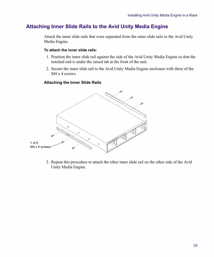
Attaching Inner Slide Rails to the Avid Unity Media Engine
Attach the inner slide rails that were separated from the outer slide rails to the Avid Unity Media Engine.
To attach the inner slide rails:
1. Position the inner slide rail against the side of the Avid Unity Media Engine so that the notched end is under the raised tab at the front of the unit.
2. Secure the inner slide rail to the Avid Unity Media Engine enclosure with three of the M4 x 4 screws.
Attaching the Inner Slide Rails
3. Repeat this procedure to attach the other inner slide rail on the other side of the Avid Unity Media Engine.
1 of 6 M4 x 4 screws

Chapter 2 Installing a Avid Unity Media Engine
34
Securing the Avid Unity Media Engine in a Rack
c You should have someone helping you lift the Avid Unity Media Engine while you are positioning it into the slide rails.
To secure the Avid Unity Media Engine to the rack enclosure:
1. Lift and position the Avid Unity Media Engine so that the inner slide rails secured to the Avid Unity Media Engine align with the outer slide rails secured to the rack.
2. Push the front of the Avid Unity Media Engine flush against the front mounting rail. The holes in the Avid Unity Media Engine front panel align with the holes in the front mounting rail.
3. From the front of the rack enclosure, insert the M5 x 10 screws through the Avid Unity Media Engine and front mounting rail, and tighten.
n You can use your own rack hardware if your rack has square holes or unique fasteners.
Front Panel Screws
Installing the Avid Unity Media Engine DrivesTo install a drive in the Avid Unity Media Engine:
1. Locate the drives that came with your Avid Unity Media Engine.
2. Select one drive.
3. Push the drive carrier latch to the right to release the handle and pull the handle completely open to insert the drive carrier.
1 of 4 M5 x 10 screws
Rack enclosure front mounting rail
Configuring Considerations
35
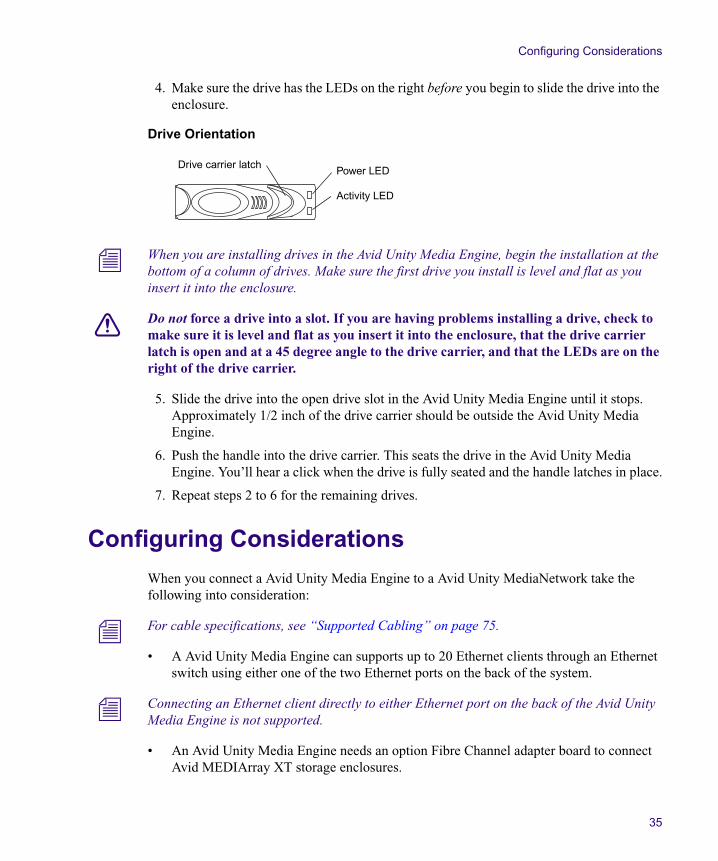
4. Make sure the drive has the LEDs on the right before you begin to slide the drive into the enclosure.
Drive Orientation
n When you are installing drives in the Avid Unity Media Engine, begin the installation at the bottom of a column of drives. Make sure the first drive you install is level and flat as you insert it into the enclosure.
c Do not force a drive into a slot. If you are having problems installing a drive, check to make sure it is level and flat as you insert it into the enclosure, that the drive carrier latch is open and at a 45 degree angle to the drive carrier, and that the LEDs are on the right of the drive carrier.
5. Slide the drive into the open drive slot in the Avid Unity Media Engine until it stops. Approximately 1/2 inch of the drive carrier should be outside the Avid Unity Media Engine.
6. Push the handle into the drive carrier. This seats the drive in the Avid Unity Media Engine. You’ll hear a click when the drive is fully seated and the handle latches in place.
7. Repeat steps 2 to 6 for the remaining drives.
Configuring Considerations
When you connect a Avid Unity Media Engine to a Avid Unity MediaNetwork take the following into consideration:
n For cable specifications, see “Supported Cabling” on page 75.
• A Avid Unity Media Engine can supports up to 20 Ethernet clients through an Ethernet switch using either one of the two Ethernet ports on the back of the system.
n Connecting an Ethernet client directly to either Ethernet port on the back of the Avid Unity Media Engine is not supported.
• An Avid Unity Media Engine needs an option Fibre Channel adapter board to connect Avid MEDIArray XT storage enclosures.
Power LED
Activity LED
Drive carrier latch
Chapter 2 Installing a Avid Unity Media Engine
36
• The Avid Unity Media Engine with the option Fibre Channel adapter board supports up to 20 Ethernet clients, up to 26 Fibre Channel clients, and up to four Avid MEDIArray XT storage enclosures.
• A 16-port and 10-port Avid MEDIAswitch is available for Fibre Channel media networks. You can stack the 16-port MEDIAswitch using a 10-gigabit (Gb) connection. If you use a stacked MEDIASwitch, you need to purchase a license for each switch.
• The Avid MEDIArray XT is the only optional storage device supported with the media engine. The maximum number of Avid MEDIArray XT enclosures per Avid media engine is four. A fully configured media engine using 500 GB drives provide 40 TB (including the 16 storage drives in the Avid Unity Media Engine).
• The media engine can be configured in the following ways:
- The Avid Unity Media Engine connected to one of more Ethernet switches (see “Connecting the Ethernet Switch” on page 38).
- The media engine connected to one Fibre Channel switch (see “Connecting the Media Engine to the Fibre Channel Switch” on page 41).
- The media engine connected to multiple Fibre Channel switches (see “Connecting the Media Engine with Two MEDIASwitch 16-4Gbs” on page 41).
- Up to four optional Avid MEDIArray XT storage enclosures (see “Connecting a Avid MEDIArray XT Drive Enclosure” on page 47).
The type of cable you use depends upon the type of switch or client you are connecting:
• If you are connecting an Ethernet switch and clients, use Category 5 or Category 6 Ethernet cables.
• If you are connecting Fiber Channel switches, clients, or additional a storage enclosure to a the MEDIASwitch you need optical simplex cables.
n For cable specifications, see “Supported Cabling” on page 75.
• If you are stacking the MEDIASwitch 16-4Gb switch, you need a 10-Gbps cable kit and licenses, provided by Avid.
Installing the Application Key
37
Installing the Application KeyTo install the application key (dongle):
1. Locate the application key in the media engine or Avid MEDIArray XT kit.
2. Attach the application key to the USB port on the back of the media engine or Avid MEDIArray XT. For an exact location see “Media Engine and MEDIArray XT Rear Panel” on page 17.
Make sure the application key is seated completely in the port.
Connecting a Keyboard, Monitor, and Mouse
An industry standard PS-2 keyboard, PS-2 mouse and VGA monitor are use to access the media engine and Avid MEDIArray XT. When installed in a rack with several servers an optional KVM switch can also be used. The keyboard, monitor, and mouse connections use the same ports described in the following procedure. Follow the instruction supplied with your KVM switch. You need to supply KVM cables that are compatible with your KVM switch.
To connect a standard keyboard, monitor, and mouse to the media engine and Avid MEDIArray XT:
1. Place the keyboard, monitor, and mouse on a suitable desktop next to the media engine and Avid MEDIArray XT in the rack.
You can also place the monitor on a shelf, and the keyboard and mouse on a sliding tray in the rack. These items are optional and can be purchased locally or from Avid.
c Do not place the monitor on top of the media engine or Avid MEDIArray XT. The enclosure is not designed to support heavy weight.
2. Attach the VGA connector on the monitor cable to the 15-pin video port on the back of the media engine or Avid MEDIArray XT. Secure the connector with the thumbscrews on the connector. For exact locations see “Media Engine and MEDIArray XT Rear Panel” on page 17.
3. Insert the connector on the keyboard cable to the PS-2 keyboard connector on the back of the media engine or Avid MEDIArray XT. The keyboard connector is at the bottom left of the connectors on the media engine or Avid MEDIArray XT.
4. Insert the connector on the mouse cable to the PS-2 mouse connector on the back of the media engine or Avid MEDIArray XT. The mouse connector is directly top connector (above the keyboard connector).
Chapter 2 Installing a Avid Unity Media Engine
38
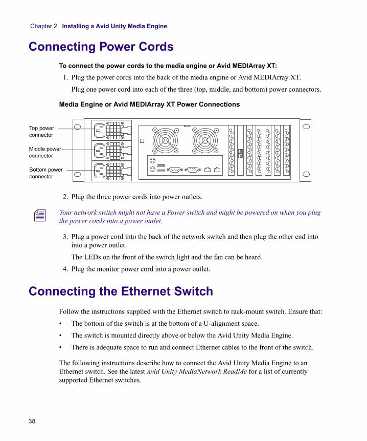
Connecting Power CordsTo connect the power cords to the media engine or Avid MEDIArray XT:
1. Plug the power cords into the back of the media engine or Avid MEDIArray XT.
Plug one power cord into each of the three (top, middle, and bottom) power connectors.
Media Engine or Avid MEDIArray XT Power Connections
2. Plug the three power cords into power outlets.
n Your network switch might not have a Power switch and might be powered on when you plug the power cords into a power outlet.
3. Plug a power cord into the back of the network switch and then plug the other end into into a power outlet.
The LEDs on the front of the switch light and the fan can be heard.
4. Plug the monitor power cord into a power outlet.
Connecting the Ethernet Switch
Follow the instructions supplied with the Ethernet switch to rack-mount switch. Ensure that:
• The bottom of the switch is at the bottom of a U-alignment space.
• The switch is mounted directly above or below the Avid Unity Media Engine.
• There is adequate space to run and connect Ethernet cables to the front of the switch.
The following instructions describe how to connect the Avid Unity Media Engine to an Ethernet switch. See the latest Avid Unity MediaNetwork ReadMe for a list of currently supported Ethernet switches.
Top power connector
Middle power connector
Bottom power connector
Connecting the Ethernet Switch
39
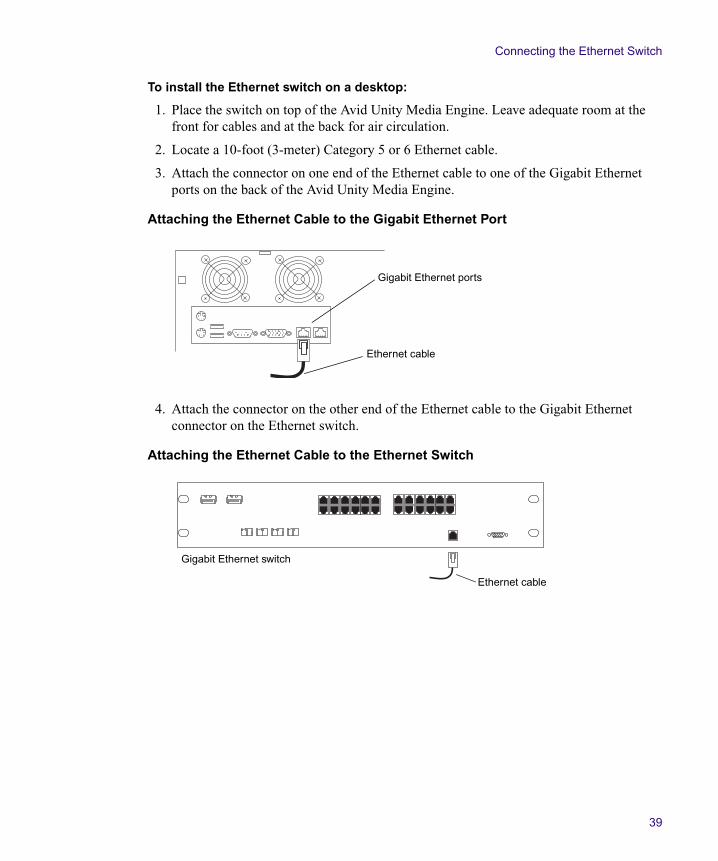
To install the Ethernet switch on a desktop:
1. Place the switch on top of the Avid Unity Media Engine. Leave adequate room at the front for cables and at the back for air circulation.
2. Locate a 10-foot (3-meter) Category 5 or 6 Ethernet cable.
3. Attach the connector on one end of the Ethernet cable to one of the Gigabit Ethernet ports on the back of the Avid Unity Media Engine.
Attaching the Ethernet Cable to the Gigabit Ethernet Port
4. Attach the connector on the other end of the Ethernet cable to the Gigabit Ethernet connector on the Ethernet switch.
Attaching the Ethernet Cable to the Ethernet Switch
Gigabit Ethernet ports
Ethernet cable
Ethernet cable
Gigabit Ethernet switch
Chapter 2 Installing a Avid Unity Media Engine
40
Connecting the Fibre Channel Switch
The MEDIASwitch connects the MediaNetwork workgroup to several MediaNetwork clients. The switch allows the MediaNetwork clients to use the storage simultaneously. The switch prevents work interruptions by allowing other clients in the workgroup to continue working if one or more clients go offline. There are two Fiber Channel switch models qualified:
• MEDIASwitch 16 4-Gb switch
• MEDIASwitch 10 4-Gb switch
You must connect the Avid Unity Media Engine to the Unity MediaNetwork system with at least one of the MEDIASwitch. See the latest Avid Unity MediaNetwork ReadMe for a list of currently supported Ethernet switches.
n The MEDIASwitch 16 4-Gb switches are the only switches that Avid supports in a stacked configuration. Only a two switch is supported.
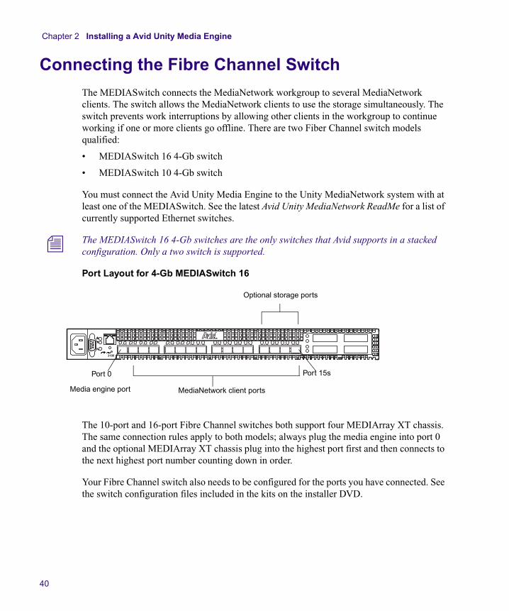
Port Layout for 4-Gb MEDIASwitch 16
The 10-port and 16-port Fibre Channel switches both support four MEDIArray XT chassis. The same connection rules apply to both models; always plug the media engine into port 0 and the optional MEDIArray XT chassis plug into the highest port first and then connects to the next highest port number counting down in order.
Your Fibre Channel switch also needs to be configured for the ports you have connected. See the switch configuration files included in the kits on the installer DVD.
a
Media engine port MediaNetwork client ports
Optional storage ports
Port 15sPort 0
Connecting the Fibre Channel Switch
41
Connecting the Media Engine to the Fibre Channel Switch
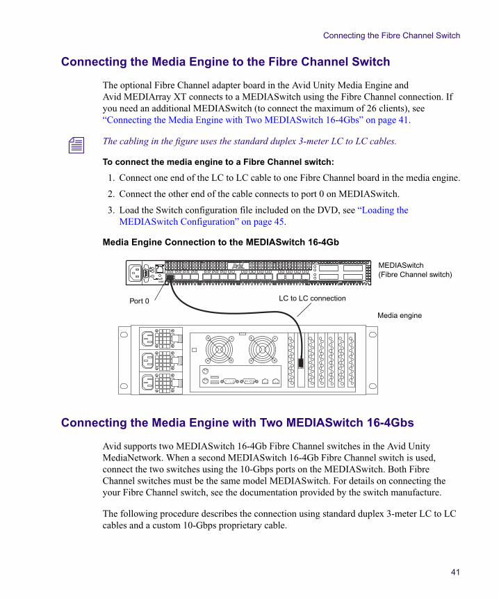
The optional Fibre Channel adapter board in the Avid Unity Media Engine and Avid MEDIArray XT connects to a MEDIASwitch using the Fibre Channel connection. If you need an additional MEDIASwitch (to connect the maximum of 26 clients), see “Connecting the Media Engine with Two MEDIASwitch 16-4Gbs” on page 41.
n The cabling in the figure uses the standard duplex 3-meter LC to LC cables.
To connect the media engine to a Fibre Channel switch:
1. Connect one end of the LC to LC cable to one Fibre Channel board in the media engine.
2. Connect the other end of the cable connects to port 0 on MEDIASwitch.
3. Load the Switch configuration file included on the DVD, see “Loading the MEDIASwitch Configuration” on page 45.
Media Engine Connection to the MEDIASwitch 16-4Gb
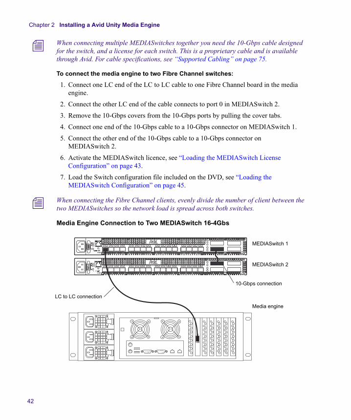
Connecting the Media Engine with Two MEDIASwitch 16-4Gbs
Avid supports two MEDIASwitch 16-4Gb Fibre Channel switches in the Avid Unity MediaNetwork. When a second MEDIASwitch 16-4Gb Fibre Channel switch is used, connect the two switches using the 10-Gbps ports on the MEDIASwitch. Both Fibre Channel switches must be the same model MEDIASwitch. For details on connecting the your Fibre Channel switch, see the documentation provided by the switch manufacture.
The following procedure describes the connection using standard duplex 3-meter LC to LC cables and a custom 10-Gbps proprietary cable.
a
Media engine
MEDIASwitch (Fibre Channel switch)
Port 0 LC to LC connection
Chapter 2 Installing a Avid Unity Media Engine
42
n When connecting multiple MEDIASwitches together you need the 10-Gbps cable designed for the switch, and a license for each switch. This is a proprietary cable and is available through Avid. For cable specifications, see “Supported Cabling” on page 75.
To connect the media engine to two Fibre Channel switches:
1. Connect one LC end of the LC to LC cable to one Fibre Channel board in the media engine.
2. Connect the other LC end of the cable connects to port 0 in MEDIASwitch 2.
3. Remove the 10-Gbps covers from the 10-Gbps ports by pulling the cover tabs.
4. Connect one end of the 10-Gbps cable to a 10-Gbps connector on MEDIASwitch 1.
5. Connect the other end of the 10-Gbps cable to a 10-Gbps connector on MEDIASwitch 2.
6. Activate the MEDIASwitch licence, see “Loading the MEDIASwitch License Configuration” on page 43.
7. Load the Switch configuration file included on the DVD, see “Loading the MEDIASwitch Configuration” on page 45.
n When connecting the Fibre Channel clients, evenly divide the number of client between the two MEDIASwitches so the network load is spread across both switches.
Media Engine Connection to Two MEDIASwitch 16-4Gbs
a
a
Media engine
MEDIASwitch 1
MEDIASwitch 2
10-Gbps connection
LC to LC connection
Connecting the Fibre Channel Switch
43
Loading the MEDIASwitch License Configuration
This section describes how to activate the MEDIASwitch 16-4G license. You are responsible for purchasing the License keys to enable the MEDIASwitch. License upgrades for the 16-port MEDIASwitch can be purchased to support 20-ports and to add 4-Gbps port speed capability to ports 0 – 15. The license is also required if you are stacking switches. To purchase a license key, contact your switch distributor, authorized reseller, or Avid representative. Follow the instruction provided with your License key to obtain the Authorization Code, the instructions include the following:
• Record the serial number of the MEDIASwitch 16-4G (SANsurfer)
• Logging on to the Qlogic web site: support.qlogic.com
• Answer the questions in the License Key Activation Center
• Record the Authorization Code and perform the following procedure
To activate a switch license using SANsurfer Switch Manager:
1. Connect the switch to a power source using the power cords. The switch powers on automatically.
n You only need to connect one power supply if you are just doing the license activation and plan on powering the switch off when finished.
2. Connect the switch’s Ethernet management port to an Ethernet port on a local workstation that is configured with a static IP address.
3. Install the SANsurfer Switch Manager software included with the switch following the on-screen instructions.
4. After the software is loaded, click the Start button and click > Programs > SANsurfer_SwitchMgr and select SANsurfer_SwitchMgr.
5. When the application starts, select Open an Existing Fabric and click Proceed.
6. Enter the following:
- You can leave the Fabric Name blank
- The IP address of 192.168.1.129 (this is the default IP address depending on whether or not you have changed your switch IP address).
- At the login: type admin
- At the password: type password (all lower case)
7. Click Add Fabric.
8. A non-secure connection window opens, click OK.
The Topology window opens, showing you the selected switch in your Fabric.
Chapter 2 Installing a Avid Unity Media Engine
44
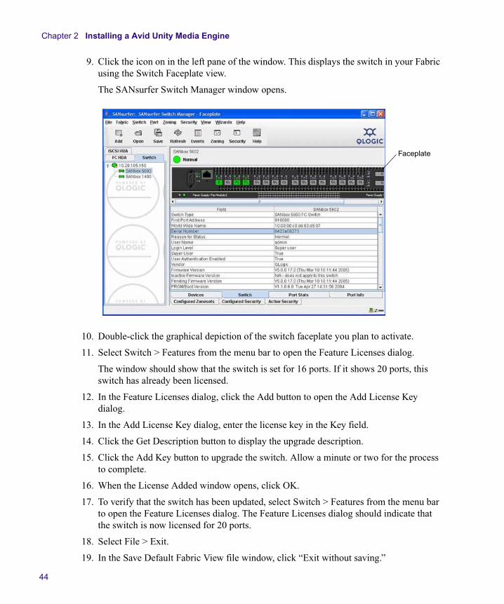
9. Click the icon on in the left pane of the window. This displays the switch in your Fabric using the Switch Faceplate view.
The SANsurfer Switch Manager window opens.
10. Double-click the graphical depiction of the switch faceplate you plan to activate.
11. Select Switch > Features from the menu bar to open the Feature Licenses dialog.
The window should show that the switch is set for 16 ports. If it shows 20 ports, this switch has already been licensed.
12. In the Feature Licenses dialog, click the Add button to open the Add License Key dialog.
13. In the Add License Key dialog, enter the license key in the Key field.
14. Click the Get Description button to display the upgrade description.
15. Click the Add Key button to upgrade the switch. Allow a minute or two for the process to complete.
16. When the License Added window opens, click OK.
17. To verify that the switch has been updated, select Switch > Features from the menu bar to open the Feature Licenses dialog. The Feature Licenses dialog should indicate that the switch is now licensed for 20 ports.
18. Select File > Exit.
19. In the Save Default Fabric View file window, click “Exit without saving.”
Faceplate
Connecting the Fibre Channel Switch
45
20. Do one of the following:
t Unplug the power and Ethernet connections if you were only activating the license.
t Continue with “Loading the MEDIASwitch Configuration” on page 45.
Loading the MEDIASwitch Configuration
This section describes how to configure the MEDIASwitch using the MEDIASwitch Manager software. The same software is used for both the MEDIASwitch 16 4-Gb switch and MEDIASwitch 10 4-Gb switch.
n The MEDIASwitch Manager software is the same application as the SANsurfer Switch Manager software that has been branded for Avid. This MEDIASwitch Manager application is located on the DVD with the MediaNetwork kit. Ether application can be used in the following procedure.
To load the MEDIASwitch configuration file:
1. Connect the switch to a power source using the power cords. The switch powers on automatically.
2. Connect the switch’s Ethernet management port to an Ethernet port on a local workstation that is configured with a static IP address.
3. Install the MEDIASwitch Manager software included with the MediaNetwork software kit on the DVD, following the on-screen instructions.
4. Click the Start button and click > Programs >MEDIASwitch_Manager_16 and select MEDIASwitch_Manager.
The MEDIASwitch Manager window opens.
5. Click Add. (This requires an IP address, login, and password) and click Proceed.
The Add a New Fabric window opens.
6. Enter the following:
- You can leave the Fabric Name blank
- The IP address of 192.168.1.129 (Depending on whether or not you have changed your switch IP address.
- At the login: type admin
- At the password: type password (all lower case)
7. Click Add Fabric.
Chapter 2 Installing a Avid Unity Media Engine
46
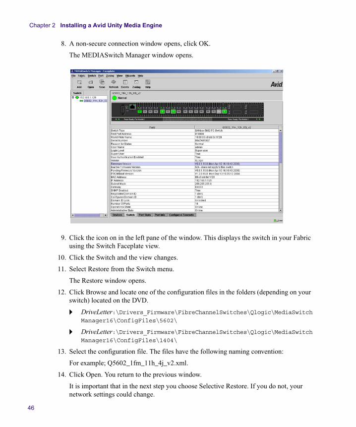
8. A non-secure connection window opens, click OK.
The MEDIASwitch Manager window opens.
9. Click the icon on in the left pane of the window. This displays the switch in your Fabric using the Switch Faceplate view.
10. Click the Switch and the view changes.
11. Select Restore from the Switch menu.
The Restore window opens.
12. Click Browse and locate one of the configuration files in the folders (depending on your switch) located on the DVD.
t DriveLetter:\Drivers_Firmware\FibreChannelSwitches\Qlogic\MediaSwitchManager16\ConfigFiles\5602\
t DriveLetter:\Drivers_Firmware\FibreChannelSwitches\Qlogic\MediaSwitchManager16\ConfigFiles\1404\
13. Select the configuration file. The files have the following naming convention:
For example; Q5602_1fm_11h_4j_v2.xml.
14. Click Open. You return to the previous window.
It is important that in the next step you choose Selective Restore. If you do not, your network settings could change.
Connecting a Avid MEDIArray XT Drive Enclosure
47
15. Click Selective Restore at the bottom left of the Window.
The Select Restore Activation window opens.
16. Deselect “Network Properties.”
17. Select Configured Zoning.
18. Click restore from the middle of the window.
19. Click Yes.
The Select Zone to be Activated window opens.
20. Click OK. You return to the Message window and it shows confirmation as the installation occurs.
21. When the “Restore Completed OK” message appears in the window click Close.
22. From the File Menu select “Save Default Fabric View File.” A dialog box opens asking to set an encryption code.
23. Do not type anything and click OK.
This saves the view of the configured switch configuration so you do not need the IP address the next time you open the file.
Connecting a Avid MEDIArray XT Drive Enclosure
The Avid MEDIArray XT drive enclosure lets you expand your storage capacity by adding up to four enclosures to the media engine.
To connect the Avid MEDIArray XT drive enclosure to the media engine:
1. Mount the Avid MEDIArray XT drive enclosure in a rack directly above or below Fibre Channel MEDIASwitch that the is connected to the media engine.
c Do not set the Avid MEDIArray XT drive enclosure directly on top of any other components on the rack. The Avid MEDIArray XT is too heavy to be supported by other rack components.
2. Locate the 10-foot (3-meter) optical cable.
3. Attach the connector on one end optical cable to the Fibre Channel connector on adapter board on the back of the Avid MEDIArray XT drive enclosure. Secure the optical cable by firmly pushing the connector into the optical port.
4. Attach the connector on the other end of the optical cable to port 15 on the Fibre Channel switch. Secure the optical cable by firmly pushing the connector into the optical port.
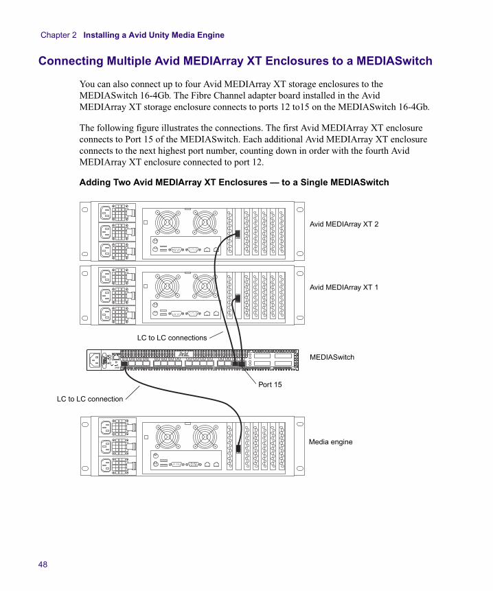
Chapter 2 Installing a Avid Unity Media Engine
48
Connecting Multiple Avid MEDIArray XT Enclosures to a MEDIASwitch
You can also connect up to four Avid MEDIArray XT storage enclosures to the MEDIASwitch 16-4Gb. The Fibre Channel adapter board installed in the Avid MEDIArray XT storage enclosure connects to ports 12 to15 on the MEDIASwitch 16-4Gb.
The following figure illustrates the connections. The first Avid MEDIArray XT enclosure connects to Port 15 of the MEDIASwitch. Each additional Avid MEDIArray XT enclosure connects to the next highest port number, counting down in order with the fourth Avid MEDIArray XT enclosure connected to port 12.
Adding Two Avid MEDIArray XT Enclosures — to a Single MEDIASwitch
a MEDIASwitch
Avid MEDIArray XT 2
Avid MEDIArray XT 1
Media engine
Port 15
LC to LC connection
LC to LC connections
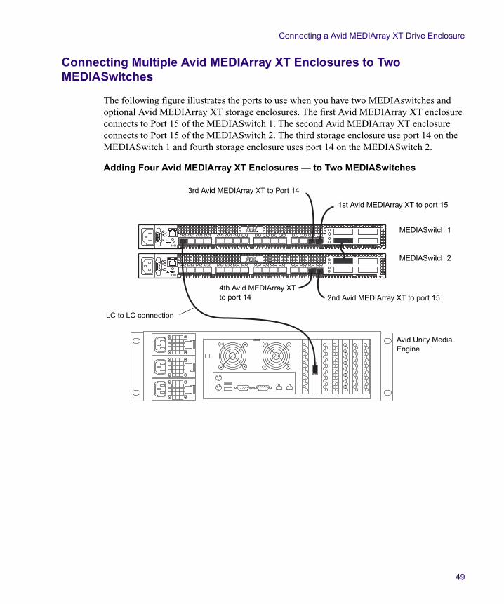
Connecting a Avid MEDIArray XT Drive Enclosure
49
Connecting Multiple Avid MEDIArray XT Enclosures to Two MEDIASwitches
The following figure illustrates the ports to use when you have two MEDIAswitches and optional Avid MEDIArray XT storage enclosures. The first Avid MEDIArray XT enclosure connects to Port 15 of the MEDIASwitch 1. The second Avid MEDIArray XT enclosure connects to Port 15 of the MEDIASwitch 2. The third storage enclosure use port 14 on the MEDIASwitch 1 and fourth storage enclosure uses port 14 on the MEDIASwitch 2.
Adding Four Avid MEDIArray XT Enclosures — to Two MEDIASwitches
a
a
MEDIASwitch 1
MEDIASwitch 2
Avid Unity Media Engine
LC to LC connection
4th Avid MEDIArray XT to port 14
3rd Avid MEDIArray XT to Port 14
1st Avid MEDIArray XT to port 15
2nd Avid MEDIArray XT to port 15
Chapter 2 Installing a Avid Unity Media Engine
50
Connecting a Workgroup to an In-House Network
To allow the clients in your workgroup to use other network services, you can connect the workgroup to your in-house Ethernet local area network (LAN).
If you have multiple workgroups, you can connect each Ethernet switch directly to the LAN, or cascade the Ethernet switches and connect only one of them to the LAN.
n Avid does not install, configure, or troubleshoot in-house LANs. If you are having trouble with your LAN, consult your Information Services department or your network vendor.
c When you are connecting the Avid Unity Media Engine to an in-house network, make sure you use only Category 5 or Category 6 Ethernet cables. Using other cable types can cause performance problems.
c Connect the media engine to an in-house network using the Ethernet switch. Using the built-in 1000BASE-T Ethernet connector on the Avid Unity Media Engine can cause an increase in login time for all the attached Ethernet clients.
To connect a single Ethernet switch to the site network:
1. Attach an Ethernet cable to a port on the Ethernet switch.
2. Attach the other end of the Ethernet cable to the built-in Ethernet connection on the back of the Avid Unity Media Engine. For an exact location see “Media Engine and MEDIArray XT Rear Panel” on page 17.
n If you have multiple workgroups and would like to cascade the switches to have a single Ethernet connection, contact your local Information Services department.
Turning On the Media Engine or Avid MEDIArray XT Hardware
When you turn on the power to your media engine or Avid MEDIArray XT hardware, you must do it in the following order so that media engine will see all of its connected components.
To turn on the power for each component:
1. The Ethernet switch does not have a Power switch. It turns on when you plug the power cord into a power outlet.
2. Turn on the Power switch for the monitor.
Configuring the Media Engine or Avid MEDIArray XT Using Windows Setup
51
3. If you have Avid MEDIArray XT storage push the black push-button switch at the top center on the front of the system.
4. Push the black push-button switch at the top center on the front of the media engine.
Watch the boot sequence begin in the monitor. Wait for the Windows operating system to load before you attempt to use the media engine software.
n It takes approximately 3 minutes for the boot sequence to complete and another minute for the Windows operating system to load.
Configuring the Media Engine or Avid MEDIArray XT Using Windows Setup
The first time you boot your media engine and Avid MEDIArray XT, it runs the Windows Setup utility to set several Windows operating system parameters. You’ll need to have the Windows software kit available when you run the utility. It contains the Windows license number you need to type in as part of the configuration.
To set up the Windows operating system:
1. The Windows Setup utility starts and the Windows Setup dialog box opens showing the License Agreement screen.
2. Click the Agree radio button to accept the license.
3. Click Next. The Regional Settings screen appears.
t If you are outside the United States, customize the system and locale settings, and the keyboard for your location.
t If you are in the United States, continue.
4. Click Next. The Personalize Your Software screen appears.
5. Type the system administrator’s name in the Name text box.
6. Type the company name in the Organization text box.
7. Click Next. The Your Product Key screen appears.
8. Type the Product Key from the Certificate of Authenticity in the Product key text box. The certificate is located on the side of the media engine and Avid MEDIArray XT.
9. Click Next. The License Modes screen appears.
10. Click the Per Server radio button and set the number of concurrent connections to the number of Ethernet clients the application key allows. For example, if your application key is set for 12 Ethernet clients, set this value to 12.
11. Click Next. The Computer Name and Administrator Password screen appears.
Chapter 2 Installing a Avid Unity Media Engine
52
12. Type the name you want to use for the media engine or Avid MEDIArray XT in the Computer name text box.
n Avid recommends you use an administrator password to prevent unauthorized use of the Administrator account.
13. Type the password you want to use for the Administrator account in the Administrator Password text box.
14. Confirm the password by retyping the password in the Confirm Password text box.
15. Click Next. The Date and Time Settings screen appears. Set the correct date, time, and time zone for the media engine or Avid MEDIArray XT.
16. Click the “Automatically adjust clock for daylight saving changes” check box if your location observes daylight saving time.
17. Click Next. The Network Settings screen appears.
18. Click the Typical radio button. The network settings are site dependent and will be set later during the media engine or Avid MEDIArray XT configuration in “Configuring the Avid Unity Media Engine” on page 53.
19. Click Next. The Workgroup and Computer Domain screen appears.
20. Click No. The workgroup and domain settings are site dependent and will be set later during the media engine or Avid MEDIArray XT configuration in “Configuring the Avid Unity Media Engine” on page 53. The Performing Final Tasks screen appears, followed by the Complete the Windows XP Setup Wizard screen.
21. Click Finish. The Windows XP operating system is loaded.
Your media engine or Avid MEDIArray XT hardware installation is complete. Continue with “Configuring the Avid Unity Media Engine” on page 53 to configure the media engine or Avid MEDIArray XT and to install the software.
Chapter 3
Configuring the Avid Unity Media Engine
This chapter describes network and Windows operating system parameters that need setting along with instructions creating workspaces using the Avid Unity MediaNetwork software on the media engine.
Topics in this chapter include:
• Windows Operating System and Network Settings
• Installing the Media Engine and Avid MEDIArray XT Software
• Setting the Virtual File Manager Name
• Configuring the MediaNetwork Software
• Mounting Workspaces
• Sharing MediaNetwork Workspaces
• Allowing Network Installation of Ethernet Client Software
• Connecting Avid Unity MediaNetwork Clients
Windows Operating System and Network Settings
Your media engine and Avid MEDIArray XT ships with the Windows operating system installed. If you need to re image the internal drives with the Windows operating system see “Using the Product Recovery DVD-ROM” on page 95. Use the information in the following sections to configure the media engine and Avid MEDIArray XT with the correct date and time, computer name, and network properties.
Chapter 3 Configuring the Avid Unity Media Engine
54
Setting the Date, Time, and Time Zone
You need to correctly set the date, time, time zone, and daylight saving time option on each media engine and Avid MEDIArray XT
n If you just completed “Configuring the Media Engine or Avid MEDIArray XT Using Windows Setup” on page 51, you can continue with “Specifying a Unique Computer Name” on page 54.
To set the date, time, time zone, and daylight saving time option on the media engine and Avid MEDIArray XT:
1. Double-click the time in the taskbar. The Date/Time Properties dialog box opens.
2. Set the date and time using the Date & Time tab.
3. Click the Time Zone tab.
4. Set the time zone for the location of the media engine or Avid MEDIArray XT By default, Windows sets the time zone to “(GMT - 8:00) Pacific Time (US & Canada), Tijuana.”
5. Make sure the “Automatically adjust clock for daylight saving changes” option is selected if your location observes daylight saving time.
6. Click OK to close the Date/Time Properties dialog box and save the settings.
Specifying a Unique Computer Name
To specify a unique computer name by which clients identify your media engine and Avid MEDIArray XT:
1. Right-click the My Computer icon on the desktop, and select Properties. The System Properties dialog box opens.
2. Click the Network Identification tab.
3. Click the Properties button. The Identification Changes dialog box opens.
4. Type the media engine or Avid MEDIArray XT name in the Computer name text box.
5. Determine if you need to select the Domain or Workgroup in the “Member of” section at the bottom of the dialog box. Contact your network administrator for assistance.
6. Click OK.
7. Close all open windows and dialog boxes.
Windows Operating System and Network Settings
55
IP Addressing Strategies When Connecting to a Network
Your Avid Unity Media Engine and Ethernet clients each client must be configured with a unique, valid IP address and subnet mask. Your site network administrator should determine how best to allocate IP addresses for systems on your in-house network, bearing in mind the following:
• You must assign a static IP address to the Gigabit Ethernet adapter on the media engine — the Ethernet clients are configured to locate the media engine using this address.
• You can assign static IP addresses to the Ethernet clients or use DHCP to obtain them dynamically if you have a DHCP server on the network.
• However you assign the Ethernet client IP addresses, the media engine and all clients must have addresses in the same subnet.
Configuring the Media Engine Network Properties
You need to configure the network properties for each media engine so it can communicate with the network. Each media engine has two built-in 1000BASE-T connections. You need to provide a static IP address and subnet mask for the Gigabit Ethernet adapter.
To configure network properties for the Gigabit Ethernet adapter:
1. Right-click the My Network Places icon on the desktop, and select Properties. The Network and Dial-up Connections dialog box opens.
2. Select View > Details. The window changes to show details about its contents.
3. Locate the Local Area Connection that is identified as Alacritech Accelerator.
4. Double-click this Local Area Connection’s icon. The Local Area Connection Status dialog box opens.
5. Click the Properties button. The Local Area Connection’s Properties dialog box opens.
6. Select the Internet Protocol (TCP/IP) option.
7. Click the Properties button. The Internet Protocol (TCP/IP) Properties dialog box opens.
8. Select the “Use the following IP address” option.
9. Type a unique IP address in the IP address text box (see “IP Addressing Strategies When Connecting to a Network” on page 55), and press Enter. The media engine should fill in the subnet mask appropriately. If not, type the appropriate subnet mask in the Subnet mask text box.
10. If necessary, type a gateway IP address in the Default gateway text box.
11. If necessary, type a Preferred and Alternate DNS server IP address in the Preferred DNS server and Alternate DNS server text boxes. For information on setting up a DNS server, see “Configuring a DNS Server” on page 77.
Chapter 3 Configuring the Avid Unity Media Engine
56
12. Click the Advanced button. The Advanced TCP/IP Settings dialog box opens.
13. Click the DNS tab.
14. If necessary, type a DNS name in the “DNS suffix for the connection” text box.
15. Click OK to close each of the open dialog boxes and save the changes.
16. Close all the remaining open windows and dialog boxes.
17. Click the Start button, and select Shut Down. The Shut Down Windows dialog box opens.
18. Select Restart from the menu, and click OK. The media engine reboots.
Installing the Media Engine and Avid MEDIArray XT Software
The MediaNetwork software allows the media engine to share MediaNetwork workspaces. This software is supplied on the Avid Unity MediaNetwork DVD-ROM.
To install the MediaNetwork software on the media engine or Avid MEDIArray XT:
1. Locate the MediaNetwork DVD-ROM.
2. Insert the DVD-ROM into the media engine or Avid MEDIArray XT DVD-ROM drive. The DVD-ROM is set to auto-start and opens the Avid Unity Installation window. This takes approximately 30 seconds.
If the DVD-ROM does not auto-start, you can start the installation manually as follows:
a. Double-click the My Computer icon on the desktop. The My Computer window opens.
b. Right-click the DVD-ROM icon, and select AutoPlay. The Avid Unity Installation window opens.
3. Click Product Installers. The screen changes to a list of available product installers.
4. Click Avid Unity Media Engine Components. The screen changes to a list of available Avid Unity Media Engine components.
5. Click Install Avid Unity Media Engine. The InstallShield Wizard opens and displays the Minimum Requirements screen.
6. Click Next. The screen changes to the Welcome screen.
7. Accept the default values presented by the InstallShield Wizard. When the Setup Status screen appears, it shows a progress indicator while the software is being installed.
8. On the InstallShield Wizard Complete screen, click “Yes, I want to restart my computer now.”
Setting the Virtual File Manager Name
57
9. Click Finish to complete installing the media engine or Avid MEDIArray XT software, and reboot the media engine or Avid MEDIArray XT.
10. Log in to the media engine or Avid MEDIArray XT as Administrator.
To verify that the LANshare software is installed correctly:
1. Right-click the My Computer icon on the desktop, and select Manage. The Computer Management window opens.
2. Expand Services and Applications.
3. Click Services. A list of services appears in the right section of the window.
4. Locate the Avid Unity PortServer service and check that:
- Status — Started
- Startup Type — Automatic
Setting the Virtual File Manager NameYou need to set the Virtual File Manager name to a name different from the Computer Name you set earlier.
To set the Virtual File Manager name:
1. Click the Start Button, and select Programs > AvidUnity > Setup Manager. The Setup Manager window opens.
2. Select File > General Configuration. The General Configuration Options dialog box opens.
3. In the Virtual File Manager Name text box, type FC at the end of the existing File Manager name. The Virtual File Manager name cannot be the same as the media engine name.
4. Click OK to close the File Manager Failover Configuration dialog box.
5. Leave the Setup Manager window open.
Configuring the MediaNetwork Software
You need to configure the MediaNetwork software to create workspace. The software and configuration tools are described in the Avid Unity MediaNetwork Administration Guide. The guide describes the MediaNetwork software and the tools. This configuration requires that you:
• Create a drive set
• Create an allocation group
Chapter 3 Configuring the Avid Unity Media Engine
58
• Create one or more workspaces
• Create user accounts
Creating a Drive Set
The drive set defines the drives that the MediaNetwork software can use to store data. Each MediaNetwork workgroup can have only one drive set.
To create a drive set:
1. Start the Setup Manager. See the Avid Unity MediaNetwork Administration Guide for additional information about using the Setup Manager.
2. Click Raw Drives in the left section of the window.
n You can create your drive set with no spare drives or two spare drives. Having spare drives allows you to perform online drive repairs if a drive fails. If you are not running the optional UnityRAID™ protection software, you should consider having spare drives.
3. Select the drives you want in the drive set in the right section of the window.
4. Select Drive Set > Create Data Drive Set.
5. Click OK. The drive set is created.
6. If you did not use all of the drives in the drive set, select the remaining drives in the right section of the window, and select Drives > Make Drive Spare.
7. Click Data Drive Set in the left section of the window. All of the drives should move from Raw Drives to Data Drive Set.
8. Quit the Setup Manager.
Creating an Allocation Group
An allocation group defines how the drives in a drive set are partitioned to store data. If you have drives of different sizes, they must be in separate allocation groups. You need a minimum of two drives per allocation group.
To create an allocation group:
1. Open the Administration Tool. See the Avid Unity Administration Guide or Help for additional information about using the Administration Tool.
2. Click the Allocation Groups tab.
3. Click the Partition Disk Set icon in the left section of the window. All of the drives should appear in the right section of the window.
4. Select each of the drives by clicking the check box before the drive number.
Configuring the MediaNetwork Software
59
n For best performance, Avid recommends you create a single allocation group using all 16 drives. You can then create multiple workspaces within the allocation group.
5. Click the New Group button. A dialog box opens asking if you are sure you want to create the allocation group.
6. Click Yes. The allocation group is created.
7. Leave the Administration Tool running.
Creating Workspaces
Workspaces are locations to store and segregate data. You can allow users to access some or all of the workspaces, and assign permissions for how each user can access the data in a workspace.
n All new workspaces are created with protection enabled. Avid recommends you leave your workspaces protected. Protection creates a copy of the files you store in a workspace. The file copy resides on different drives from the original file. When several clients want to play the same file, the MediaNetwork software steers clients to either the original or the copy of the file to provide maximum playback performance. Protection also allows you to rebuild the data on a drive, if one of your drives should fail.
To create a workspace:
1. Click the Workspace tab in the Administration Tool. See the Avid Unity MediaNetwork Administration Guide for additional information about using the Administration Tool.
2. Click the turn-down arrow before Partition Disk Set. The allocation group appears.
3. Click the Allocation Group icon and then click the New Workspace button. A 1-GB workspace is created.
4. Click the turn-down arrow before the allocation group. The workspace appears.
5. Click the workspace name, type the name you want for the workspace, and press Enter. The workspace name changes.
6. Resize the workspace, to make it larger, by pressing the At key while clicking the resize handle and dragging it to the right.
7. Repeat steps 3 to 6 to create as many workspaces as you might need.
8. Leave the Administration Tool running.
n You can create as many workspaces as you need to support different projects. Due to the physical restrictions of drive letters, the media engine or Avid MEDIArray XT can only mount a maximum of 21 workspaces for client use.
Chapter 3 Configuring the Avid Unity Media Engine
60
Creating User Accounts
User accounts allow individual users, or groups of users, access to the LANshare workgroup. These accounts allow users to mount or map MediaNetwork workspaces on their Avid workstations.
To create a user account:
1. Click the User tab in the Administration Tool. See the Avid Unity MediaNetwork Administration Guide for additional information about using the Administration Tool.
2. Click the turn-down arrow before Partition Disk Set. The allocation group appears.
3. Click the turn-down arrow before the allocation group. The workspaces appear.
4. Click the New User button in the right section of the window. A new user is created and appears in the column head area.
5. Double-click the user name. The Change User Name dialog box opens.
6. Type the desired user name in the text box and click OK. The user name changes.
7. Click the user name and then click the Set Password button. The Set Password dialog box opens.
8. Type the desired password in the text box and click OK. The user’s password is saved.
9. Click the permissions below the user name for each workspace, and set them accordingly to No Access (N), Read (R), or Read/Write (R/W).
10. Repeat steps 4 to 9 for each user.
11. Close the Administration Tool.
Mounting Workspaces
On a media engine, you can mount some MediaNetwork workspaces to specific drive letters. The AISPortServer.ini file is used to establish the static mapping between workspaces and drive letters.
To configure the AISPortServer.ini file:
1. Navigate to D:\Program Files\Avid Technology\AvidUnity\ PortServerStartup.
2. Open the AISPortServer.ini file using a text editor, such as WordPad.
3. Add one line for each workspace you want to map to a specific drive letter. Each line should use the format X: workspace, where X is the drive letter and workspace is the name of the workspace to mount. Workspace names are case sensitive and can have no spaces in the names.
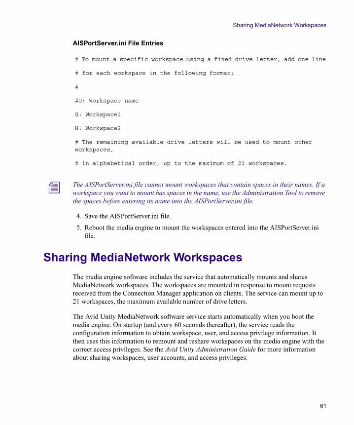
Sharing MediaNetwork Workspaces
61
AISPortServer.ini File Entries
n The AISPortServer.ini file cannot mount workspaces that contain spaces in their names. If a workspace you want to mount has spaces in the name, use the Administration Tool to remove the spaces before entering its name into the AISPortServer.ini file.
4. Save the AISPortServer.ini file.
5. Reboot the media engine to mount the workspaces entered into the AISPortServer.ini file.
Sharing MediaNetwork Workspaces
The media engine software includes the service that automatically mounts and shares MediaNetwork workspaces. The workspaces are mounted in response to mount requests received from the Connection Manager application on clients. The service can mount up to 21 workspaces, the maximum available number of drive letters.
The Avid Unity MediaNetwork software service starts automatically when you boot the media engine. On startup (and every 60 seconds thereafter), the service reads the configuration information to obtain workspace, user, and access privilege information. It then uses this information to remount and reshare workspaces on the media engine with the correct access privileges. See the Avid Unity Administration Guide for more information about sharing workspaces, user accounts, and access privileges.
# To mount a specific workspace using a fixed drive letter, add one line
# for each workspace in the following format:
#
#U: Workspace name
G: Workspace1
H: Workspace2
# The remaining available drive letters will be used to mount other workspaces,
# in alphabetical order, up to the maximum of 21 workspaces.
Chapter 3 Configuring the Avid Unity Media Engine
62
Allowing Network Installation of Ethernet Client Software
The Windows Ethernet client software installer is included as part of the Avid Unity Media Engine installation (in D:\Program Files\Avid Technology\ AvidUnity\Ethernet Client Setup), if you accepted the defaults during the installation. If you share the Ethernet Client Setup folder you (or other users with the appropriate access permissions) can install the Windows Ethernet client software on any connected Windows Ethernet client over the network without using the MediaNetwork DVD-ROM.
To share the Ethernet Client Setup folder to allow network installation of the Windows XP Ethernet client software:
1. Open Windows Explorer.
2. Navigate to D:\Program Files\Avid Technology\AvidUnity.
3. Right-click the Ethernet Client Setup folder, and select Sharing. The Ethernet Client Setup Properties dialog box opens.
4. Select the “Share this folder” option.
5. Type the name you want to use for the folder in the Share name text box.
6. Click OK. The dialog box closes and the sharing hand appears under the folder.
Connecting Avid Unity MediaNetwork Clients
You are now ready to connect clients to your media engine. You can connect supported Macintosh® or Windows clients using either Ethernet or Fibre Channel connections. Connect your clients according the Avid Unity Client Manager Guide.
Chapter 4
Troubleshooting
This chapter provides information on troubleshooting your media engine and Avid MEDIArray XT, the following topics are included:
• Ping and Tracert Commands
• Media Engine or Avid MEDIArray XT Is Whistling
• Checking the Operating System
• Removing and Replacing Drives
• Troubleshooting a Workgroup
Ping and Tracert CommandsEthernet networking is the backbone for the Avid Unity Media Engine workgroup. If your Ethernet network is not performing properly, it will affect your workgroup. The following sections describe how to use two commands, ping and tracert, to troubleshoot your network.
Ping
You can use the ping command to confirm that the physical and logical aspects of your network are configured correctly. Physical aspects include network interface card, cables, and Ethernet switches. Logical aspects include IP addresses, subnet masks, and routing.
ping works by sending a packet over the network from an originating host to a destination host. The destination host receives the packet and sends a response packet over the network to the originating host. If the originating host receives the response packet, it is a good indication that the network is configured correctly.
Chapter 4 Troubleshooting
64
You can use many options with ping. This section discusses two types of ping syntax:
ping [System Name]
where [System Name] is the network name of the remote system to which you are testing connectivity
or
ping [IP Address]
where [IP Address] is the IP address of the remote system to which you are testing connectivity.
To run the ping command:
1. Open an MS-DOS® command prompt window.
2. At the command line, type the ping command (for example, ping 192.168.10.5).
The ping result should resemble the following:
Reply from 192.168.10.5: bytes=32 time<10ms TTL=255
Reply from 192.168.10.5: bytes=32 time<10ms TTL=255
Reply from 192.168.10.5: bytes=32 time<10ms TTL=255
Reply from 192.168.10.5: bytes=32 time<10ms TTL=255
Four responses of “Reply from…” indicate the network is configured correctly and the originating and destination hosts can see each other on the network.
If any one of the responses in the ping result says:
Request timed out.
or
Destination host unreachable.
it indicates the network is not configured correctly or there are other network problems. Some items that can cause network problems are:
� Bad, loose, or incorrectly connected cables
� An incorrectly configured IP address or subnet mask on a local or remote system
� Excessive network traffic
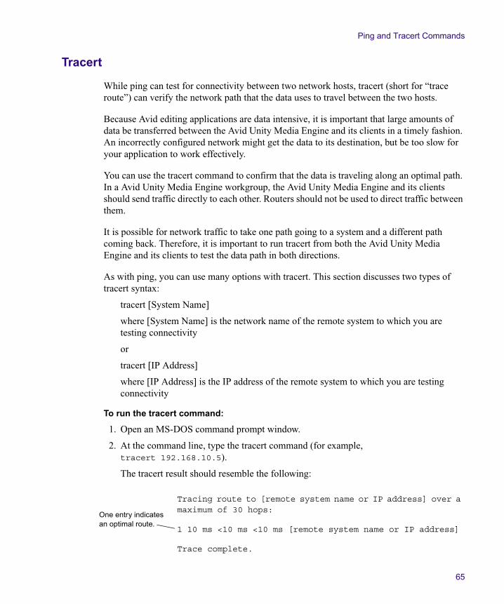
Ping and Tracert Commands
65
Tracert
While ping can test for connectivity between two network hosts, tracert (short for “trace route”) can verify the network path that the data uses to travel between the two hosts.
Because Avid editing applications are data intensive, it is important that large amounts of data be transferred between the Avid Unity Media Engine and its clients in a timely fashion. An incorrectly configured network might get the data to its destination, but be too slow for your application to work effectively.
You can use the tracert command to confirm that the data is traveling along an optimal path. In a Avid Unity Media Engine workgroup, the Avid Unity Media Engine and its clients should send traffic directly to each other. Routers should not be used to direct traffic between them.
It is possible for network traffic to take one path going to a system and a different path coming back. Therefore, it is important to run tracert from both the Avid Unity Media Engine and its clients to test the data path in both directions.
As with ping, you can use many options with tracert. This section discusses two types of tracert syntax:
tracert [System Name]
where [System Name] is the network name of the remote system to which you are testing connectivity
or
tracert [IP Address]
where [IP Address] is the IP address of the remote system to which you are testing connectivity
To run the tracert command:
1. Open an MS-DOS command prompt window.
2. At the command line, type the tracert command (for example, tracert 192.168.10.5).
The tracert result should resemble the following:
Tracing route to [remote system name or IP address] over a maximum of 30 hops:
1 10 ms <10 ms <10 ms [remote system name or IP address]
Trace complete.
One entry indicates an optimal route.
Chapter 4 Troubleshooting
66
If your network is configured correctly, the tracert result will show only one entry and then indicate that the trace is complete. More than one entry indicates that the traffic is going through a router, which significantly affects performance.
If your tracert result shows more than one entry, most likely there is an incorrect IP address or subnet mask configuration on the local host.
Media Engine or Avid MEDIArray XT Is Whistling
Problem: The media engine or Avid MEDIArray XT is making a whistling sound.
Possible Cause: One of the power supply modules might have failed. Perform the following checks:
• Make sure all the power supply modules are plugged in.
• Make sure the power cords are plugged into an active electrical circuit.
• Make sure one of the electrical circuits has not overloaded and tripped the circuit breaker. If the power cords are plugged into different circuits, check both circuits for a tripped circuit breaker.
• Press the red button near the top center on the back of the media engine or Avid MEDIArray XT. The whistling should stop.
n The media engine or Avid MEDIArray XT can continue to run if one of the power supply modules is turned off or fails, or if one of the power cords is not plugged in.
• Contact Avid Customer Support for further assistance and possible power supply module replacement.
Checking the Operating System
The Avid Unity Media Engine runs Windows 2003 server operating system and Avid MEDIArray XT runs the Windows XP operating system with Service Pack 2.
To verify the Windows operating system and service pack on the media engine or Avid MEDIArray XT:
1. Right-click the My Computer icon on the desktop, and select Properties. The System Properties dialog box opens.
2. Click the General tab. The System section lists the version of the operating system and the service pack that are installed on the media engine or MEDIArray XT.
Make sure your media engine or MEDIArray XT also has all the critical Windows updates.
Removing and Replacing Drives
67
If you reinstall the Windows operating system for any reason, make sure you perform a default installation (accept all the standard installation recommendations) of the Windows operating system.
You also need to reinstall drivers for the Gigabit Ethernet adapter board, the Fibre Channel adapter boards, or the 3ware drive controller board. These drivers are provided on the MediaNetwork DVD-ROM in the Drivers_Firmware folder. Each driver is in its own folder, labeled by its function.
Removing and Replacing Drives
You should only remove and replace a drive in your Data Drive Set of your media engine or Avid MEDIArray XT when specifically asked by Avid Customer Support.
c Removing a drive from the enclosure while it is running might cause a loss of data. Make sure you use the following procedure to remove drives from the media engine or MEDIArray XT.
Removing a Drive
To remove a drive from the media engine or Avid MEDIArray XT:
c Drives should only be removed by Avid-trained and Avid-authorized personnel.
n If you are removing a drive on a media engine or Avid MEDIArray XT, have all the clients and media servers unmount any workspaces before you continue.
1. Start the Setup Manager and select File Manager > Stop File Manager. A message box opens asking if you are sure you want to stop the File Manager.
2. Click Yes. A dialog box opens while the File Manager is stopping.
3. Click Data Drive Set in the left section of the window and select the drive you want to remove from the Data Drive Set by clicking it.
4. Select Drives > Identify. The LED for the drive flashes and can be seen on the front of the media engine or Avid MEDIArray XT. Note the drive location and number.
5. Click the Start button, and select Shut Down. The Shut Down Windows dialog box opens.
6. Select Shut down from the menu, and click OK. The Windows operating system shuts down and turns off the media engine or Avid MEDIArray XT. This takes approximately 1 minute.
Chapter 4 Troubleshooting
68
7. Push down on the right side of the handle to release the handle.
8. Pull the handle to unlatch the drive and slide drive carrier out of the media engine or Avid MEDIArray XT.
Replacing a Drive
To replace a drive in the media engine or Avid MEDIArray XT:
1. Locate the replacement drive. Make sure the handle on the drive carrier is unlatched and pulled out as far as possible.
2. Slide the drive into the open drive location in the media engine or Avid MEDIArray XT until it stops moving. Approximately 1/2 inch of the drive carrier should be outside the media engine or Avid MEDIArray XT.
3. Push the handle into the drive carrier. This seats the drive in the media engine or Avid MEDIArray XT. You’ll hear a click when the drive is fully seated and the handle latches in place.
4. Start the media engine or Avid MEDIArray XT by pushing the Power button on the front of the media engine or Avid MEDIArray XT.
Troubleshooting a Workgroup
The following sections describe how to troubleshoot some common media engine or Avid MEDIArray XT issues.
Understanding Disk Error Logging and the DEAN Light
Avid Unity MediaNetwork logs the following three new disk errors from SATA disks located in the media engine or Avid MEDIArray XT:
• Long read command time — indicates a disk read request took longer than expected.
• Long write command time — indicates a disk write request took longer than expected.
• STATUS_IO_DEVICE_ERROR — indicates a hardware error with the disk or controller.
A major result of the new error logging procedure also produces the possibility of lighting/setting the Disk Error Analysis Needed (DEAN) more frequently. Although this indicates a legitimate drive error, it does not necessarily indicate a bad disk.
The three new errors are stored in the following two locations:
• Unityclientlog.txt file
• IBEviewer
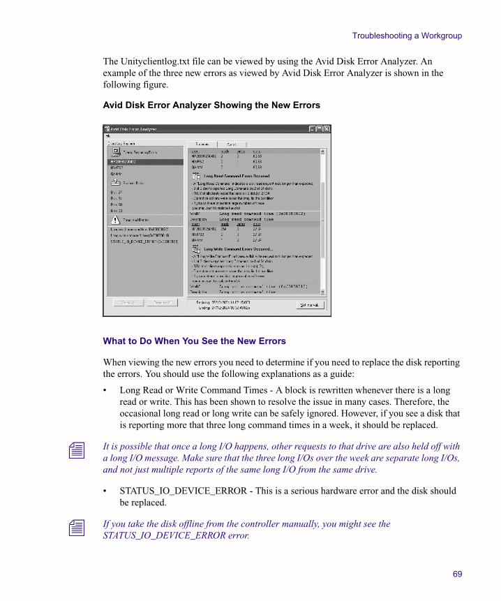
Troubleshooting a Workgroup
69
The Unityclientlog.txt file can be viewed by using the Avid Disk Error Analyzer. An example of the three new errors as viewed by Avid Disk Error Analyzer is shown in the following figure.
Avid Disk Error Analyzer Showing the New Errors
What to Do When You See the New Errors
When viewing the new errors you need to determine if you need to replace the disk reporting the errors. You should use the following explanations as a guide:
• Long Read or Write Command Times - A block is rewritten whenever there is a long read or write. This has been shown to resolve the issue in many cases. Therefore, the occasional long read or long write can be safely ignored. However, if you see a disk that is reporting more that three long command times in a week, it should be replaced.
n It is possible that once a long I/O happens, other requests to that drive are also held off with a long I/O message. Make sure that the three long I/Os over the week are separate long I/Os, and not just multiple reports of the same long I/O from the same drive.
• STATUS_IO_DEVICE_ERROR - This is a serious hardware error and the disk should be replaced.
n If you take the disk offline from the controller manually, you might see the STATUS_IO_DEVICE_ERROR error.
Chapter 4 Troubleshooting
70
Avid Editing Application Performance Issues
Problem: The Avid editing application you are running is performing slowly or, potentially, not running.
Possible Cause: The media engine and the client with the performance problems are not on the same subnet mask, forcing the data to go through additional routing while being transferred between the two systems. If the data transfer is slow enough, it can cause the Avid editing application to perform poorly or to stop functioning.
Data transfer between the media engine and its clients must occur directly. You can use the tracert utility to verify whether or not the data transfer uses a direct, optimal path. See “Tracert” on page 65 for more information.
You can also test the throughput from the client to the media engine using the Avid Performance Meter. For information on using the Avid Performance Meter, see the Avid MediaNetwork Administration Guide.
Workspaces Are Not Available to an Ethernet Client
Problem: No workspaces are available for mounting on an client.
Possible Cause: The user account, under which the user has logged in to the client, does not exist either in the MediaNetwork Administration Tool or the media engine Windows domain. For more information on properly setting up user accounts, see the Avid Unity MediaNetwork Administration Guide.
Possible Cause: The user account does not have permissions to mount workspaces.
Macintosh Client Cannot Mount Shared Workspaces
Problem: A Macintosh Ethernet client cannot mount workspaces shared by the media engine.
Possible Cause: Macintosh clients cannot connect to the media engine without installing additional software (DAVE®) to allow them to see the Windows network. DAVE is included with the MediaNetwork software and must be correctly configured to function within a LANshare workgroup. See the Avid Unity MediaNetwork Macintosh Ethernet Client Setup Guide for information about configuring the DAVE software.
c Each Macintosh client needs to have a separate DAVE license to use the DAVE software. If two clients use the same license, you will have conflicts between these clients when they try to connect to the media engine.
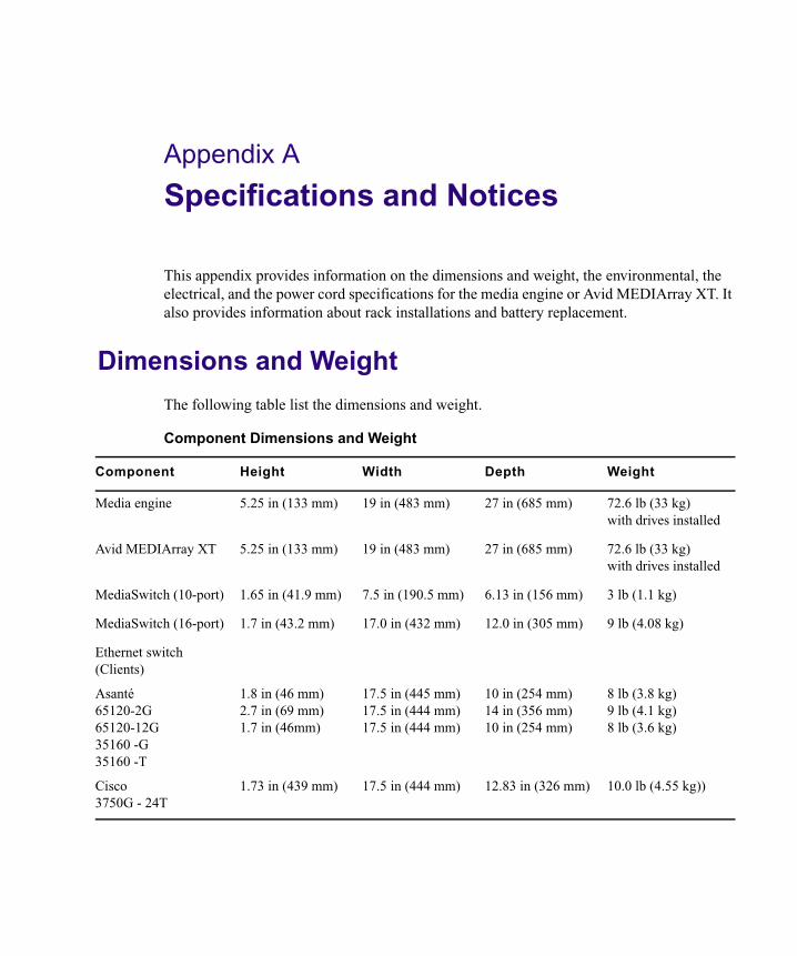
Appendix A
Specifications and Notices
This appendix provides information on the dimensions and weight, the environmental, the electrical, and the power cord specifications for the media engine or Avid MEDIArray XT. It also provides information about rack installations and battery replacement.
Dimensions and Weight
The following table list the dimensions and weight.
Component Dimensions and Weight
Component Height Width Depth Weight
Media engine 5.25 in (133 mm) 19 in (483 mm) 27 in (685 mm) 72.6 lb (33 kg) with drives installed
Avid MEDIArray XT 5.25 in (133 mm) 19 in (483 mm) 27 in (685 mm) 72.6 lb (33 kg) with drives installed
MediaSwitch (10-port) 1.65 in (41.9 mm) 7.5 in (190.5 mm) 6.13 in (156 mm) 3 lb (1.1 kg)
MediaSwitch (16-port) 1.7 in (43.2 mm) 17.0 in (432 mm) 12.0 in (305 mm) 9 lb (4.08 kg)
Ethernet switch (Clients)
Asanté 65120-2G65120-12G35160 -G35160 -T
Cisco3750G - 24T
1.8 in (46 mm)2.7 in (69 mm)1.7 in (46mm)
1.73 in (439 mm)
17.5 in (445 mm)17.5 in (444 mm)17.5 in (444 mm)
17.5 in (444 mm)
10 in (254 mm)14 in (356 mm)10 in (254 mm)
12.83 in (326 mm)
8 lb (3.8 kg)9 lb (4.1 kg)8 lb (3.6 kg)
10.0 lb (4.55 kg))
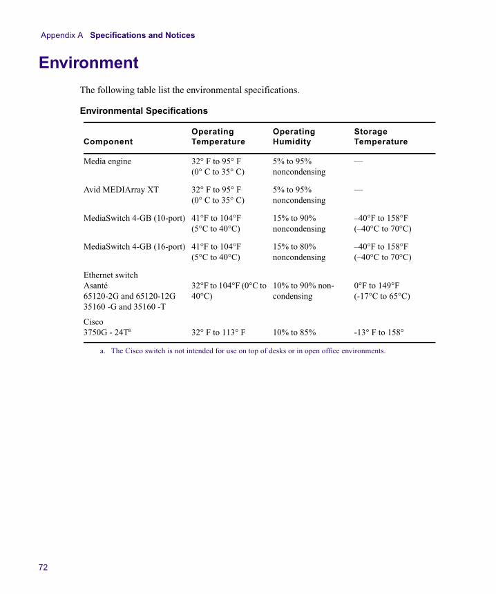
Appendix A Specifications and Notices
72
Environment
The following table list the environmental specifications.
Environmental Specifications
ComponentOperating Temperature
OperatingHumidity
Storage Temperature
Media engine 32° F to 95° F (0° C to 35° C)
5% to 95% noncondensing
—
Avid MEDIArray XT 32° F to 95° F (0° C to 35° C)
5% to 95% noncondensing
—
MediaSwitch 4-GB (10-port) 41°F to 104°F (5°C to 40°C)
15% to 90% noncondensing
–40°F to 158°F (–40°C to 70°C)
MediaSwitch 4-GB (16-port) 41°F to 104°F (5°C to 40°C)
15% to 80% noncondensing
–40°F to 158°F (–40°C to 70°C)
Ethernet switch Asanté 65120-2G and 65120-12G 35160 -G and 35160 -T
Cisco3750G - 24Ta
a. The Cisco switch is not intended for use on top of desks or in open office environments.
32°F to 104°F (0°C to 40°C)
32° F to 113° F
10% to 90% non-condensing
10% to 85%
0°F to 149°F (-17°C to 65°C)
-13° F to 158°
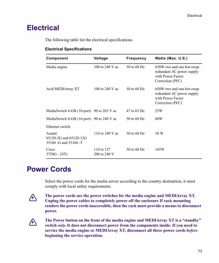
Electrical
73
Electrical
The following table list the electrical specifications.
Power Cords
Select the power cords for the media server according to the country destination; it must comply with local safety requirements.
w The power cords are the power switches for the media engine and MEDIArray XT. Unplug the power cables to completely power off the enclosure If rack mounting renders the power cords inaccessible, then the rack must provide a means to disconnect power.
w The Power button on the front of the media engine and MEDIArray XT is a “standby” switch only. It does not disconnect power from the components inside. If you need to service the media engine or MEDIArray XT, disconnect all three power cords before beginning the service operation.
Electrical Specifications
Component Voltage Frequency Watts (Max. U.S.)
Media engine 100 to 240 V ac 50 to 60 Hz 650W two and one hot-swap redundant AC power supply with Power Factor Correction (PFC)
Avid MEDIArray XT 100 to 240 V ac 50 to 60 Hz 650W two and one hot-swap redundant AC power supply with Power Factor Correction (PFC)
MediaSwitch 4-GB (10-port) 90 to 265 V ac 47 to 63 Hz 25W
MediaSwitch 4-GB (16-port) 90 to 240 V ac 50 to 60 Hz 60W
Ethernet switch
Asanté 65120-2G and 65120-12G35160 -G and 35160 -T
Cisco3750G - 24Ts
110 to 240 V ac
110 to 127200 to 240 V
50 to 60 Hz
50 to 60 Hz
10 W
165W
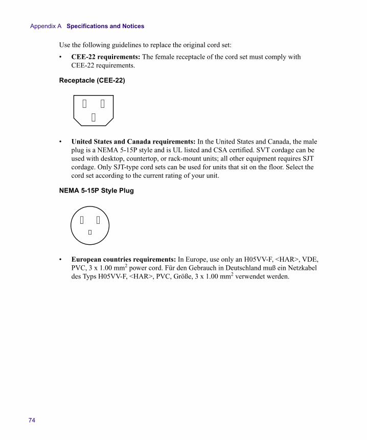
Appendix A Specifications and Notices
74
Use the following guidelines to replace the original cord set:
• CEE-22 requirements: The female receptacle of the cord set must comply with CEE-22 requirements.
Receptacle (CEE-22)
• United States and Canada requirements: In the United States and Canada, the male plug is a NEMA 5-15P style and is UL listed and CSA certified. SVT cordage can be used with desktop, countertop, or rack-mount units; all other equipment requires SJT cordage. Only SJT-type cord sets can be used for units that sit on the floor. Select the cord set according to the current rating of your unit.
NEMA 5-15P Style Plug
• European countries requirements: In Europe, use only an H05VV-F, <HAR>, VDE, PVC, 3 x 1.00 mm2 power cord. Für den Gebrauch in Deutschland muß ein Netzkabel des Typs H05VV-F, <HAR>, PVC, Größe, 3 x 1.00 mm2 verwendet werden.
Supported Cabling
75
Supported Cabling
Avid supports the following cable types for Avid Unity MediaNetwork connections.
n If you need run your cable distances, call Avid Customer Support for supported cable and accessory information.
w The optical cable is an international Class 1 laser product per IEC 60825-1 Amendment 2(2001) and IEC 60825-2 1997. Operating this product in a manner inconsistent with intended usage and specification may result in hazardous radiation exposure. Tampering with this laser based product or operating this product outside the limits of this specification may be considered an act of “manufacturing,” and will require, under law, recertification of the modified product with the U.S. Food and Drug Administration (21 CFR 1040). Published by Picolight Incorporated. All rights reserved.
Supported Cables
Cable Name Function Maximum Distance
RJ45 Cat 5E or Cat 6 Ethernet cable (minimum).
To connect the Avid Unity Media Engine to the Ethernet switch,
To connect the Ethernet switches to the Avid Unity Ethernet clients.
100 Meters; If using CAT5E the cable must be rated for 350 MHz for maximum length.
Optical Fibre Channel cable, available from Avid.
Read the important information below this table when using an optical cable.
To connect the optical Fibre Channel ports to the Fibre Channel switches, servers, clients, and storage.
The maximum length of the cable is defined by the micron and modal bandwidth MHz-km (megahertz over one kilometer)
Avid recommends the following 4.25 Gb/s, 850 nm, LC/LC cable guidelines:
• MMF 62.5 micron cable
Modal bandwidth 200 MHz-km, 0.5 – 70 mModal bandwidth 160 MHz-km, 0.5 – 55 m
• MMF 50 micron cable
Modal bandwidth 2000 MHz-km, 0.5 – 270 mModal bandwidth 500 MHz-km, 0.5 – 150 mModal bandwidth 400 MHz-km, 0.5 – 130 m
Appendix A Specifications and Notices
76
Lithium Battery Replacement
The battery in the Avid Unity Media Engine and Avid MEDIArray must only be replaced by qualified personnel. Contact Avid Customer Support for assistance.
WARNING
w Danger of explosion if battery is incorrectly replaced. Replace with only the same or equivalent type recommended by the manufacturer. Dispose of used batteries according to the manufacturer’s instructions.
ADVARSEL!
w Lithiumbatteri - Eksplosionsfare ved fejlagtig håndtering. Udskiftning må kun ske med batteri af samme fabrikat og type. Levér det brugte batteri tilbage til leverandøren.
ADVARSEL!
w Lithiumbatteri - Eksplosjonsfare. Ved utskifting benyttes kun batteri som anbefalt av apparatfabrikanten. Brukt batteri returneres apparatleverandøren.
VARNING
w Explosionsfara vid felaktigt batteribyte. Använd samma batterityp eller en ekvivalent typ som rekommenderas av apparattillverkaren. Kassera använt batteri enligt fabrikantens instruktion.
VAROITUS
w Paristo voi räjähtää, jos se on virheellisesti asennettu. Vaihda paristo ainoastaan laitevalmistajan suosittelemaan tyyppiin. Hävitä käytetty paristo valmistajan ohjeiden mukaisesti.
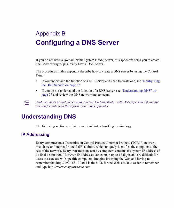
Appendix B
Configuring a DNS Server
If you do not have a Domain Name System (DNS) server, this appendix helps you to create one. Most workgroups already have a DNS server.
The procedures in this appendix describe how to create a DNS server by using the Control Panel:
• If you understand the function of a DNS server and need to create one, see “Configuring the DNS Server” on page 82.
• If you do not understand the function of a DNS server, see “Understanding DNS” on page 77 and review the DNS networking concepts.
n Avid recommends that you consult a network administrator with DNS experience if you are not comfortable with the information in this appendix.
Understanding DNS
The following sections explain some standard networking terminology.
IP Addressing
Every computer on a Transmission Control Protocol/Internet Protocol (TCP/IP) network must have an Internet Protocol (IP) address, which uniquely identifies the computer to the rest of the network. Every transmission sent by computers contains the system IP address of its final destination. However, IP addresses can contain up to 12 digits and are difficult for users to associate with specific computers. Imagine browsing the Web and having to remember that http://192.168.130.014 is the URL for the Web site. It is easier to remember and type http://www.companyname.com.
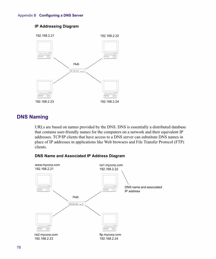
Appendix B Configuring a DNS Server
78
IP Addressing Diagram
DNS Naming
URLs are based on names provided by the DNS. DNS is essentially a distributed database that contains user-friendly names for the computers on a network and their equivalent IP addresses. TCP/IP clients that have access to a DNS server can substitute DNS names in place of IP addresses in applications like Web browsers and File Transfer Protocol (FTP) clients.
DNS Name and Associated IP Address Diagram
192.168.2.21 192.168.2.22
Hub
192.168.2.23 192.168.2.24
www.mycorp.com192.168.2.21
ns1.mycorp.com192.168.2.22
Hub
ns2.mycorp.com192.168.2.23
ftp.mycorp.com192.168.2.24
DNS name and associated IP address
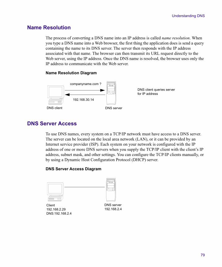
Understanding DNS
79
Name Resolution
The process of converting a DNS name into an IP address is called name resolution. When you type a DNS name into a Web browser, the first thing the application does is send a query containing the name to its DNS server. The server then responds with the IP address associated with that name. The browser can then transmit its URL request directly to the Web server, using the IP address. Once the DNS name is resolved, the browser uses only the IP address to communicate with the Web server.
Name Resolution Diagram
DNS Server Access
To use DNS names, every system on a TCP/IP network must have access to a DNS server. The server can be located on the local area network (LAN), or it can be provided by an Internet service provider (ISP). Each system on your network is configured with the IP address of one or more DNS servers when you supply the TCP/IP client with the client’s IP address, subnet mask, and other settings. You can configure the TCP/IP clients manually, or by using a Dynamic Host Configuration Protocol (DHCP) server.
DNS Server Access Diagram
companyname.com ?
192.168.30.14
DNS serverDNS client
DNS client queries server for IP address
Client192.168.2.29DNS:192.168.2.4
DNS server192.168.2.4
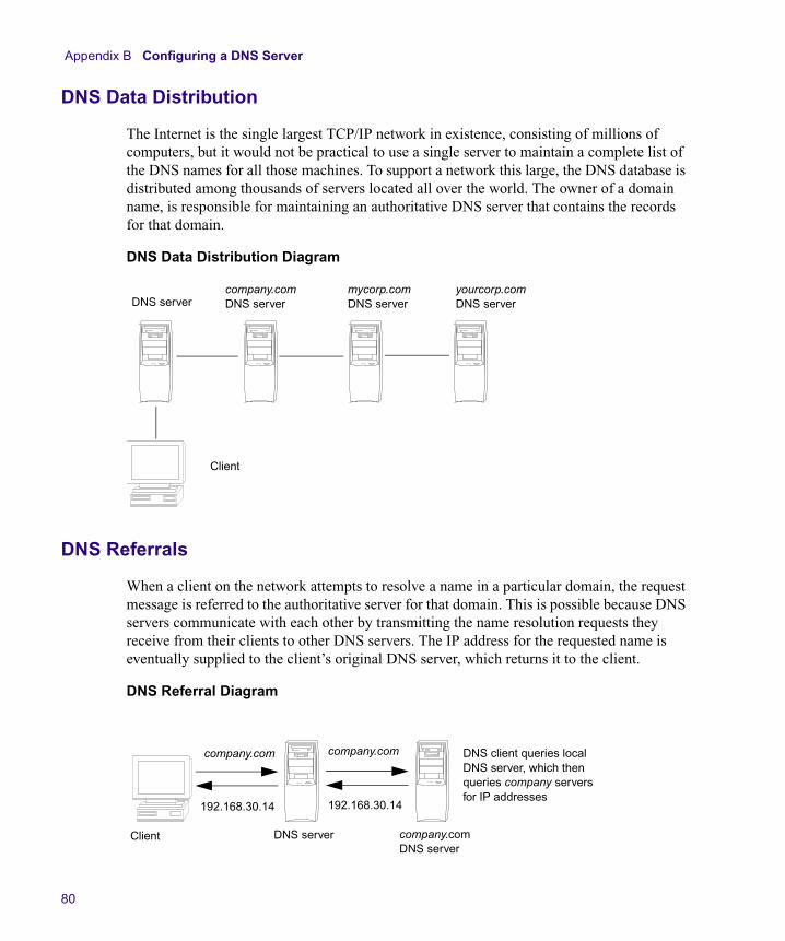
Appendix B Configuring a DNS Server
80
DNS Data Distribution
The Internet is the single largest TCP/IP network in existence, consisting of millions of computers, but it would not be practical to use a single server to maintain a complete list of the DNS names for all those machines. To support a network this large, the DNS database is distributed among thousands of servers located all over the world. The owner of a domain name, is responsible for maintaining an authoritative DNS server that contains the records for that domain.
DNS Data Distribution Diagram
DNS Referrals
When a client on the network attempts to resolve a name in a particular domain, the request message is referred to the authoritative server for that domain. This is possible because DNS servers communicate with each other by transmitting the name resolution requests they receive from their clients to other DNS servers. The IP address for the requested name is eventually supplied to the client’s original DNS server, which returns it to the client.
DNS Referral Diagram
Client
DNS servercompany.comDNS server
mycorp.comDNS server
yourcorp.comDNS server
Client DNS server company.comDNS server
192.168.30.14 192.168.30.14
company.com company.com DNS client queries local DNS server, which then queries company servers for IP addresses
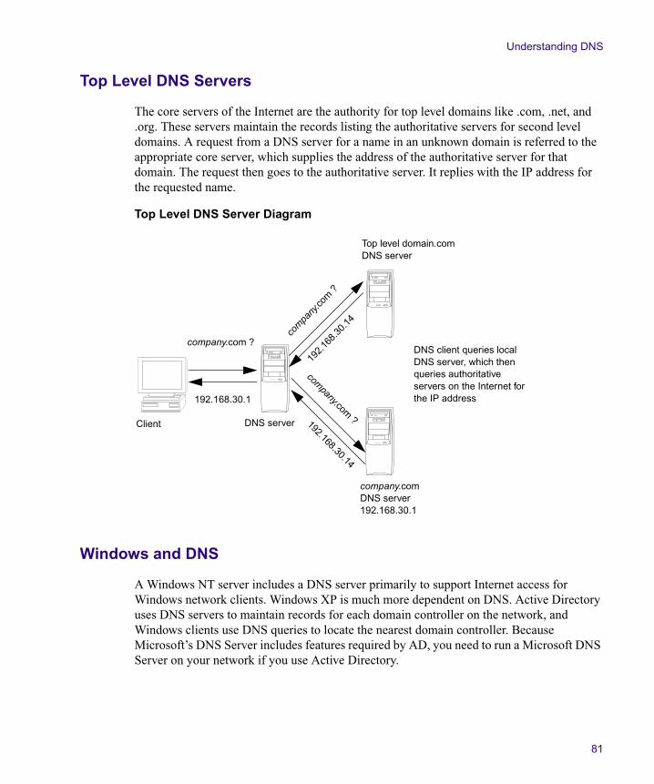
Understanding DNS
81
Top Level DNS Servers
The core servers of the Internet are the authority for top level domains like .com, .net, and .org. These servers maintain the records listing the authoritative servers for second level domains. A request from a DNS server for a name in an unknown domain is referred to the appropriate core server, which supplies the address of the authoritative server for that domain. The request then goes to the authoritative server. It replies with the IP address for the requested name.
Top Level DNS Server Diagram
Windows and DNS
A Windows NT server includes a DNS server primarily to support Internet access for Windows network clients. Windows XP is much more dependent on DNS. Active Directory uses DNS servers to maintain records for each domain controller on the network, and Windows clients use DNS queries to locate the nearest domain controller. Because Microsoft’s DNS Server includes features required by AD, you need to run a Microsoft DNS Server on your network if you use Active Directory.
Client DNS server
company.comDNS server192.168.30.1
192.168.30.1
192.
168.
30.1
4co
mpany
.com
?
company.com ?
Top level domain.comDNS server
192.168.30.14
company.com
?
DNS client queries local DNS server, which then queries authoritative servers on the Internet for the IP address
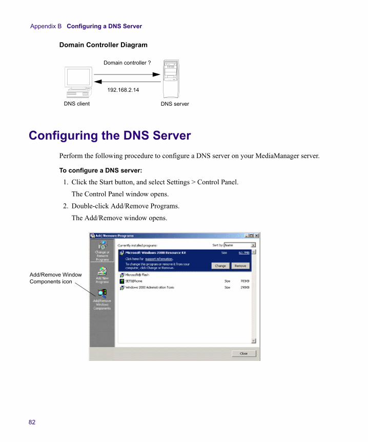
Appendix B Configuring a DNS Server
82
Domain Controller Diagram
Configuring the DNS Server
Perform the following procedure to configure a DNS server on your MediaManager server.
To configure a DNS server:
1. Click the Start button, and select Settings > Control Panel.
The Control Panel window opens.
2. Double-click Add/Remove Programs.
The Add/Remove window opens.
Domain controller ?
192.168.2.14
DNS serverDNS client
Add/Remove Window Components icon
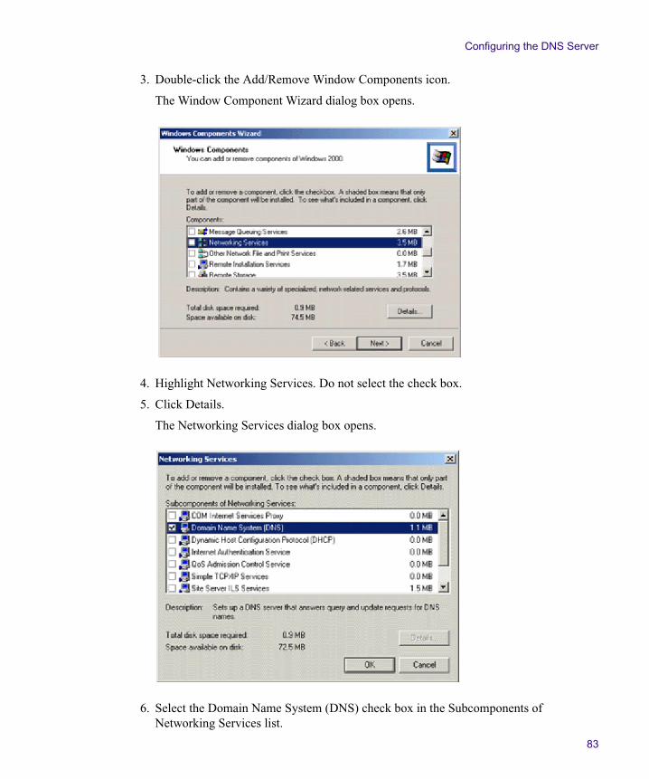
Configuring the DNS Server
83
3. Double-click the Add/Remove Window Components icon.
The Window Component Wizard dialog box opens.
4. Highlight Networking Services. Do not select the check box.
5. Click Details.
The Networking Services dialog box opens.
6. Select the Domain Name System (DNS) check box in the Subcomponents of Networking Services list.
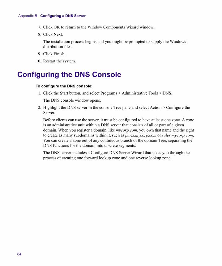
Appendix B Configuring a DNS Server
84
7. Click OK to return to the Window Components Wizard window.
8. Click Next.
The installation process begins and you might be prompted to supply the Windows distribution files.
9. Click Finish.
10. Restart the system.
Configuring the DNS ConsoleTo configure the DNS console:
1. Click the Start button, and select Programs > Administrative Tools > DNS.
The DNS console window opens.
2. Highlight the DNS server in the console Tree pane and select Action > Configure the Server.
Before clients can use the server, it must be configured to have at least one zone. A zone is an administrative unit within a DNS server that consists of all or part of a given domain. When you register a domain, like mycorp.com, you own that name and the right to create as many subdomains within it, such as paris.mycorp.com or sales.mycorp.com. You can create a zone out of any continuous branch of the domain Tree, separating the DNS functions for the domain into discrete segments.
The DNS server includes a Configure DNS Server Wizard that takes you through the process of creating one forward lookup zone and one reverse lookup zone.
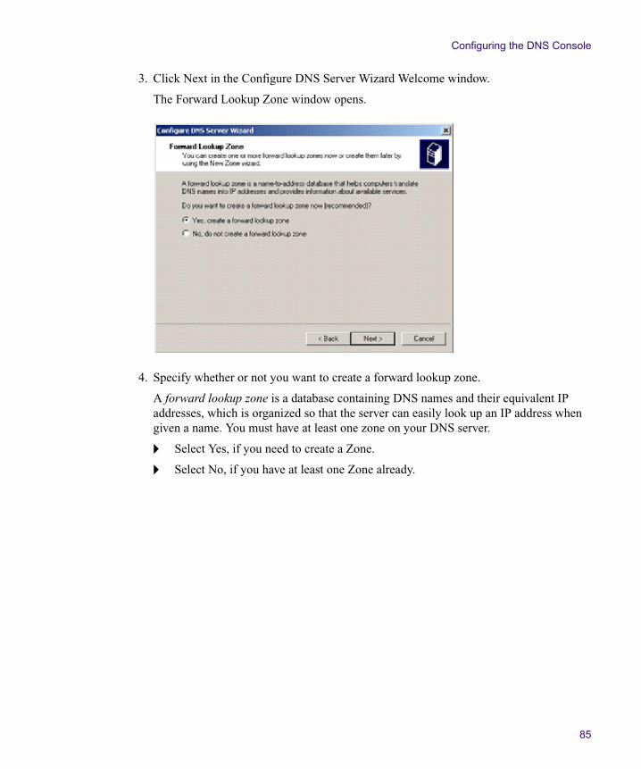
Configuring the DNS Console
85
3. Click Next in the Configure DNS Server Wizard Welcome window.
The Forward Lookup Zone window opens.
4. Specify whether or not you want to create a forward lookup zone.
A forward lookup zone is a database containing DNS names and their equivalent IP addresses, which is organized so that the server can easily look up an IP address when given a name. You must have at least one zone on your DNS server.
t Select Yes, if you need to create a Zone.
t Select No, if you have at least one Zone already.
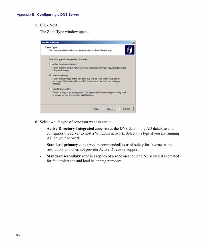
Appendix B Configuring a DNS Server
86
5. Click Next.
The Zone Type window opens.
6. Select which type of zone you want to create:
- Active Directory-Integrated zone stores the DNS data in the AD database and configures the server to host a Windows network. Select this type if you are running AD on your network.
- Standard primary zone (Avid recommended) is used solely for Internet name resolution, and does not provide Active Directory support.
- Standard secondary zone is a replica of a zone on another DNS server; it is created for fault tolerance and load balancing purposes.
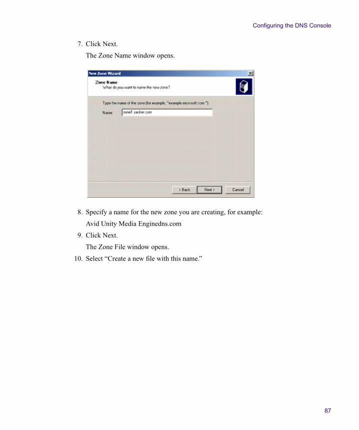
Configuring the DNS Console
87
7. Click Next.
The Zone Name window opens.
8. Specify a name for the new zone you are creating, for example:
Avid Unity Media Enginedns.com
9. Click Next.
The Zone File window opens.
10. Select “Create a new file with this name.”
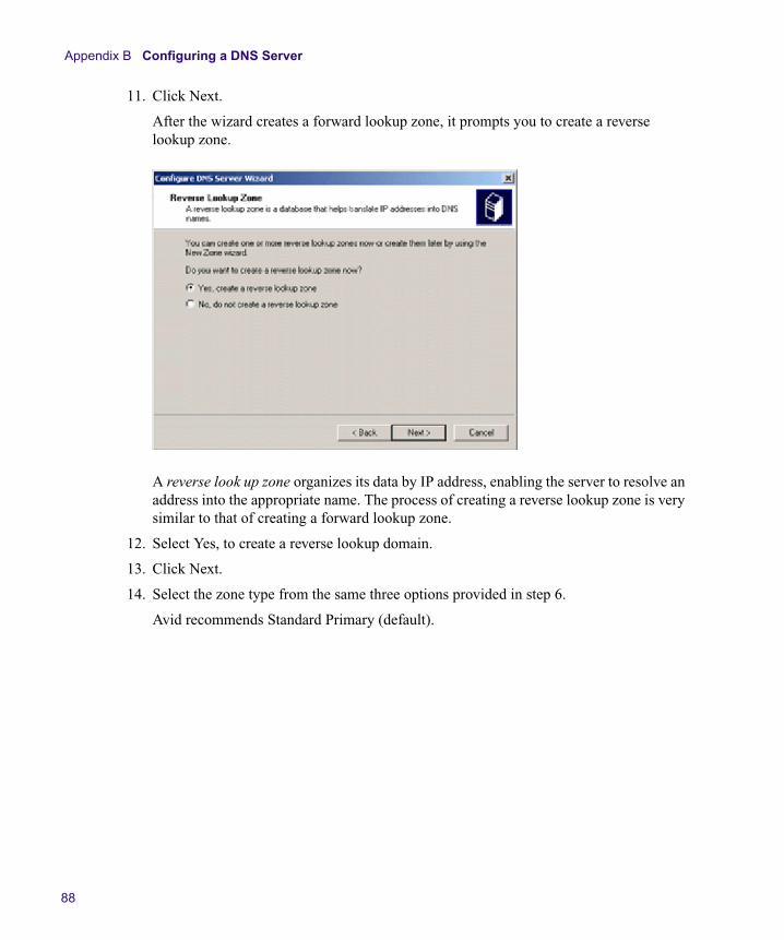
Appendix B Configuring a DNS Server
88
11. Click Next.
After the wizard creates a forward lookup zone, it prompts you to create a reverse lookup zone.
A reverse look up zone organizes its data by IP address, enabling the server to resolve an address into the appropriate name. The process of creating a reverse lookup zone is very similar to that of creating a forward lookup zone.
12. Select Yes, to create a reverse lookup domain.
13. Click Next.
14. Select the zone type from the same three options provided in step 6.
Avid recommends Standard Primary (default).
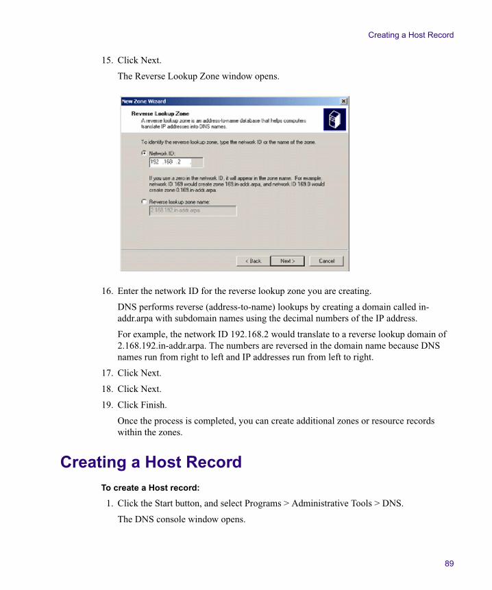
Creating a Host Record
89
15. Click Next.
The Reverse Lookup Zone window opens.
16. Enter the network ID for the reverse lookup zone you are creating.
DNS performs reverse (address-to-name) lookups by creating a domain called in-addr.arpa with subdomain names using the decimal numbers of the IP address.
For example, the network ID 192.168.2 would translate to a reverse lookup domain of 2.168.192.in-addr.arpa. The numbers are reversed in the domain name because DNS names run from right to left and IP addresses run from left to right.
17. Click Next.
18. Click Next.
19. Click Finish.
Once the process is completed, you can create additional zones or resource records within the zones.
Creating a Host RecordTo create a Host record:
1. Click the Start button, and select Programs > Administrative Tools > DNS.
The DNS console window opens.
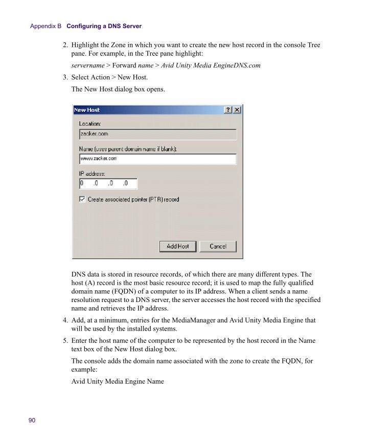
Appendix B Configuring a DNS Server
90
2. Highlight the Zone in which you want to create the new host record in the console Tree pane. For example, in the Tree pane highlight:
servername > Forward name > Avid Unity Media EngineDNS.com
3. Select Action > New Host.
The New Host dialog box opens.
DNS data is stored in resource records, of which there are many different types. The host (A) record is the most basic resource record; it is used to map the fully qualified domain name (FQDN) of a computer to its IP address. When a client sends a name resolution request to a DNS server, the server accesses the host record with the specified name and retrieves the IP address.
4. Add, at a minimum, entries for the MediaManager and Avid Unity Media Engine that will be used by the installed systems.
5. Enter the host name of the computer to be represented by the host record in the Name text box of the New Host dialog box.
The console adds the domain name associated with the zone to create the FQDN, for example:
Avid Unity Media Engine Name
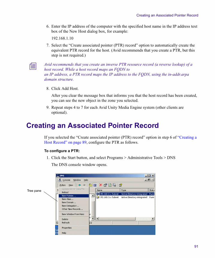
Creating an Associated Pointer Record
91
6. Enter the IP address of the computer with the specified host name in the IP address text box of the New Host dialog box, for example:
192.168.1.10
7. Select the “Create associated pointer (PTR) record” option to automatically create the equivalent PTR record for the host. (Avid recommends that you create a PTR, but this step is not required.)
n Avid recommends that you create an inverse PTR resource record (a reverse lookup) of a host record. While a host record maps an FQDN to an IP address, a PTR record maps the IP address to the FQDN, using the in-addr.arpa domain structure.
8. Click Add Host.
After you clear the message box that informs you that the host record has been created, you can see the new object in the zone you selected.
9. Repeat steps 4 to 7 for each Avid Unity Media Engine system (other clients are optional).
Creating an Associated Pointer Record
If you selected the “Create associated pointer (PTR) record” option in step 6 of “Creating a Host Record” on page 89, configure the PTR as follows.
To configure a PTR:
1. Click the Start button, and select Programs > Administrative Tools > DNS
The DNS console window opens.
Tree pane
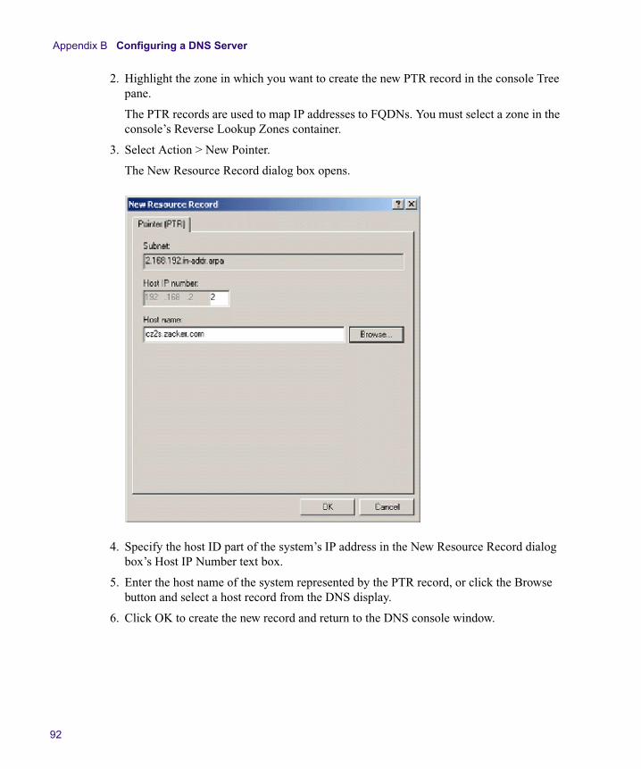
Appendix B Configuring a DNS Server
92
2. Highlight the zone in which you want to create the new PTR record in the console Tree pane.
The PTR records are used to map IP addresses to FQDNs. You must select a zone in the console’s Reverse Lookup Zones container.
3. Select Action > New Pointer.
The New Resource Record dialog box opens.
4. Specify the host ID part of the system’s IP address in the New Resource Record dialog box’s Host IP Number text box.
5. Enter the host name of the system represented by the PTR record, or click the Browse button and select a host record from the DNS display.
6. Click OK to create the new record and return to the DNS console window.
Configuring the Avid Unity Media Engine for the DNS Server
93
Configuring the Avid Unity Media Engine for the DNS Server
Once you have the DNS server configured, you need to enter DNS information for each Avid Unity Media Engine system. You can also configure other clients in your Avid Unity MediaNetwork network.
To configure the Avid Unity Media Engine for the DNS server:
1. Click the Start button, and select Settings > Network and Dialup Connections.
2. Right-click the active network adapter and select Properties.
3. Click Internet protocol TCP/IP.
4. Click Properties.
5. Select “Use the following DNS Server addresses” and type in the IP address of the DNS Server (preferably the MediaManager) in the Preferred DNS Server text box.
6. Click Advanced.
7. Click the DNS tab.
8. Select “Append these DNS suffixes (in order).”
9. Click Add and type in the DNS Name you specified, for example:
Avid Unity Media Enginedns.com
10. Click Add.
11. Click OK and close all open windows.

Appendix B Configuring a DNS Server
94
Appendix C
Using the Product Recovery DVD-ROM
This image recovery procedure is based on the Supermicro PDSMA motherboard used in the Avid Unity Media Engine and Avid MEDIArray XT. The image recovery reinstalls the Windows operating system. You should only perform this process if you are rebuilding the internal system drives and have been instructed to do so by Avid Customer Support. The product recovery offers the following two options:
t Perform a Windows installation to the 1st partition (C:). This removes the data in the C: partition only; the D: partition is not changed. You can perform this operation to replace only the operating system on your media engine or Avid MEDIArray XT.
t Perform a Windows installation to the entire drive set (C: and D:). This replaces all of the data from both partitions on your media engine or Avid MEDIArray XT. This includes removing the metadata for the media on the data drives.
c Avid recommends you backup the latest metadata file before you perform any product recovery. Metadata files are located in D:\AVIDONLY of the media engine, for example: AvidMediaNetworkMD3. When replacing your saved backup metadata file you must delete all the newly created metadata files.
When doing a Product Recovery on the C: and D: partitions and you do not want to save the media on your data drives, you must delete the data drive sets. The media engine will find the old drive sets and newly created metadata file and the Avid Unity MediaNetwork will not start until the conflict is resolved.
For more information on deleting the data drive sets, see “Deleting a Data Drive Set” in the See the Avid Unity Administration Guide or the Help. You should delete the data drive sets before doing a Product Recovery on the C: and D: partitions, although it can also be done afterward.
n This procedure restores only the Windows operating system and the hardware drivers. It does not restore the Avid Unity MediaNetwork software. The software must be reinstalled separately, after the operating system recovery is complete.
Topics in this appendix include:
• Reinstalling the Windows Operating System
• Configuring the Windows Operating System
Appendix C Using the Product Recovery DVD-ROM
96
Reinstalling the Windows Operating SystemTo reinstall the Windows operating system from the Avid Product Recovery DVD-ROM:
1. Make sure all clients unmount any workspaces they have mounted and stop the Connection Manager.
2. Stop the File Manager using the Monitor Tool.
c When performing a Product Recovery, make sure you do not have any other remote storage connected to your Avid Unity Media Engine or Avid MEDIArray XT. Remote storage would include additional internal or external drives, a USB storage device, or 1394 (FireWire®) drive. If any other storage is attached, inaccurate partitions would appear in the operating system which might cause data corruption.
3. Locate the Avid Product Recovery DVD-ROM and insert the DVD-ROM into the DVD-ROM drive.
4. Click the Start button, and select Shut Down. The Shut Down Windows dialog box opens.
5. Select the Shut down option, and click OK. The Windows operating system shuts down and turns off the system.
6. Disconnect any Fibre Channel cables connected to the rear of the system.
As the Product Recovery program scans the system for drives, external drives not included with this recovery might be detect through the Fibre Channel connection.
7. Press the Power button on the front of the Avid Unity Media Engine system. The system starts to boot, do not close any of the windows that are displayed. (Some are minimized and others are behind each other.) This can take several minutes.
n If the media engine or Avid MEDIArray XT does not boot from the DVD-ROM, you need to change the boot priority for the DVD-ROM drive to place it before the hard drive. Reboot the media engine or Avid MEDIArray XT and use Setup at the beginning of the boot process (press the F2 key when prompted) to make the change, and then repeat step 7.
8. Once the AvidPE Restore Menu appears, Type the number of the operation you want to perform at the prompt. Select one of the available options:
t 1. Recover the C: partition only.
t 2. Recover both C: and D: partitions, entire system disk (drive set).
t 3. Exit without doing a recovery.
9. A warning screen appears stating that you are about to recover the C: partition, or all partitions (depending on what you selected in step 8).
t Press Y to continue.
Configuring the Windows Operating System
97
t Press N to quit the recovery.
10. A second warning screen appears informing you again that you are about to recover the metadata.
n This second warning is not displayed if you selected 1 (recover the C: partition) in step 8.
t Type yes to continue and press Enter.
t Type no to quit the recovery press Enter.
11. A final warning screen appears informing you again that you are about to recover all data.
t Press Y to continue.
The Norton Ghost® screen appears showing the progress of the recovery. This takes approximately 20 minutes.
t Press N to quit the recovery.
A Recovery Complete windows displays when finished.
12. Press the Reset button on the front panel and remove the Avid Product Recovery DVD-ROM from the DVD-ROM drive before it restarts.
The system automatically restarts.
n The Microsoft CHKDSK (check disk) automatically runs directly after image completes and the system is restarted. The CHKDSK process runs on each logical partition (C and D) and takes about 20 seconds to complete.
13. Configure the Windows operating system as described in the following section.
Configuring the Windows Operating System
After you recover the Windows operating system, it runs the Windows Setup Wizard to set several Windows operating system parameters. You will need to have the Windows Certificate of Authenticity in the Product key number as part of the configuration. this number is located on the side of the enclosure.
To set up the Windows operating system:
1. After the media engine or Avid MEDIArray XT restarts, the Windows Setup Wizard opens., click Next.
2. Click the “I accept the agreement” radio button to accept the license.
3. Click Next. The Regional Settings screen appears.
Customize the system and local settings and your location.
Appendix C Using the Product Recovery DVD-ROM
98
4. Click Next. The Your Product Key screen appears.
5. Type the Product Key from the Certificate of Authenticity in the Product key text box. The certificate is affixed to the side of the media engine or Avid MEDIArray XT.
n The Windows Product Key Certificate of Authenticity is initially included in the shipping carton and must be attached to the side of the product.
6. (Ethernet servers only) Click Next. The License Modes screen appears.
7. (Ethernet servers only) Click the Per Server radio button and set the number of concurrent connections to the number of Ethernet clients the application key allows. For example, if your application key is set for 12 Ethernet clients, set this value to 12.
c For a Avid Unity Media Engine, do not set the number of concurrent connections to more than 20. This is the maximum number of clients that the Avid Unity Media Engine can support. Setting this value to more than 20 will impact the system performance.
8. Click Next. The Computer Name and Administrator Password screen appears.
9. Type the name you want to use for the media engine or Avid MEDIArray XT in the Computer name text box.
10. Type the password you want to use for the administrator account in the Administrator Password text box.
n Avid recommends you use an administrator password to prevent unauthorized use of the Administrator account.
11. Confirm the password by retyping the password in the Confirm Password text box.
12. Click Next. The Date and Time Settings screen appears. Set the correct date, time, and time zone for the system.
n The media engine and Avid MEDIArray XT product recovery DVD-ROMs include the daylight savings time changes that went into effect in 2007.
13. Click the “Automatically adjust clock for daylight saving changes” check box if your location observes daylight saving time.
14. Click Next. The Network Settings screen appears.
15. Click the Typical radio button. The network settings are site dependent and will be set later during the configuration.
16. Click Next. The Workgroup and Computer Domain screen appears.
17. Click No. The workgroup and domain settings are site dependent and will be set later during the configuration. The Performing Final Tasks screen appears, followed by the Complete the Windows Setup Wizard screen.
Configuring the Windows Operating System
99
18. Click Next. The Windows operating restarts.
19. Log into the media engine or Avid MEDIArray XT using your administrator name and password.
20. Reconnect the Fibre Channel cable removed earlier.
21. Continue with “Configuring the Avid Unity Media Engine” on page 53 to install the software and configure the media engine or Avid MEDIArray XT.

Appendix C Using the Product Recovery DVD-ROM
100

Appendix D
Regulatory and Safety Notices
Warnings and Cautions
w Never install equipment if it appears damaged.
w Disconnect the power cord before servicing unit.
w Only perform the services explicitly described in this document. For services or procedures not outlined in this document, speak with authorized Avid service personnel.
c Follow all warnings and cautions in the procedures.
c Operate the device within its marked electrical ratings and product usage instructions.
FCC Notice
This device complies with Part 15 of the FCC Rules. Operation is subject to the following two conditions:
1. This device may not cause harmful interference.
2. This device must accept any interference received, including interference that may cause undesired operation.
This equipment has been tested and found to comply with the limits for a Class A digital device, pursuant to Part 15 of the FCC Rules. These limits are designed to provide reasonable protection against harmful interference when the equipment is operated in a commercial environment. This equipment generates, uses, and can radiate radio frequency energy and, if not installed in accordance with the instruction manual, may cause harmful interference to radio communications. Operation of this equipment in a residential area is likely to cause harmful interference in which case the user will be required to correct the interference at his own expense.

Appendix D Regulatory and Safety Notices
102
Canadian ICES-003
This Class A digital apparatus meets all requirements of the Canadian Interference Causing Equipment Regulations.
Cet appareil numérique de la classe A respecte toutes les exigences du Règlement sur le matériel brouilleur du Canada.
European Union Notice
Declaration of Conformity (According to ISO/IEC Guide 22 and EN 45014)
Application of Council Directives:
73/23/EEC, 89/336/EEC.
Standards to which Conformity is Declared:
EN60950:1999 Third EditionCISPR 22:1997 / EN55022:1994 + A1:1995 + A2:1997 Class A EN55024:1998/EN61000 — 3-2, 4-2, 4-3, 4-4, 4-5, 4-6, 4-11
Manufacturer’s Name: Avid Technology, Inc. 1925 Andover StreetTewksbury, MA 01876, USA
European Contact: Nearest Avid Sales and Service Office or Avid Technology International B.V. Sandyford Business Center Unit 3,Dublin 18, Ireland
Type of Equipment: Information Technology Equipment
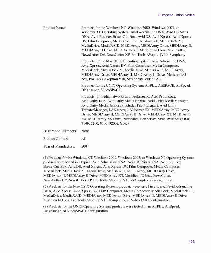
European Union Notice
103
(1) Products for the Windows NT, Windows 2000, Windows 2003, or Windows XP Operating System: products were tested in a typical Avid Adrenaline DNA, Avid DS Nitris DNA, Avid Equinox Break-Out-Box, Avid|DS, Avid Xpress, Avid Xpress DV, Film Composer, Media Composer, MediaDock, MediaDock 2+, MediaDrive, MediaRAID, MEDIArray, MEDIArray Drive, MEDIArray II, MEDIArray II Drive, MEDIArray XT, Meridien I/O box, NewsCutter, NewsCutter DV, NewsCutter XP, Pro Tools AVoption|V10, or Symphony configuration.
(2) Products for the Mac OS X Operating System: products were tested in a typical Avid Adrenaline DNA, Avid Xpress, Avid Xpress DV, Film Composer, Media Composer, MediaDock, MediaDock 2+, MediaDrive, MediaRAID, MEDIArray, MEDIArray Drive, MEDIArray II, MEDIArray II Drive, Meridien I/O box, Pro Tools AVoption|V10, Symphony, or VideoRAID configuration.
(3) Products for the UNIX Operating System: products were tested in an AirPlay, AirSpeed, DNxchange, or VideoSPACE configuration.
Product Name: Products for the Windows NT, Windows 2000, Windows 2003, or Windows XP Operating System: Avid Adrenaline DNA, Avid DS Nitris DNA, Avid Equinox Break-Out-Box, Avid|DS, Avid Xpress, Avid Xpress DV, Film Composer, Media Composer, MediaDock, MediaDock 2+, MediaDrive, MediaRAID, MEDIArray, MEDIArray Drive, MEDIArray II, MEDIArray II Drive, MEDIArray XT, Meridien I/O box, NewsCutter, NewsCutter DV, NewsCutter XP, Pro Tools AVoption|V10, Symphony
Products for the Mac OS X Operating System: Avid Adrenaline DNA, Avid Xpress, Avid Xpress DV, Film Composer, Media Composer, MediaDock, MediaDock 2+, MediaDrive, MediaRAID, MEDIArray, MEDIArray Drive, MEDIArray II, MEDIArray II Drive, Meridien I/O box, Pro Tools AVoption|V10, Symphony, VideoRAID
Products for the UNIX Operating System: AirPlay, AirSPACE, AirSpeed, DNxchange, VideoSPACE
Products for media networks and workgroups: Avid ProEncode, Avid Unity ISIS, Avid Unity Media Engine, Avid Unity MediaManager, Avid Unity MediaNetwork (includes File Manager), Avid Unity TransferManager, LANserver, LANserver EX, MEDIArray, MEDIArray Drive, MEDIArray II, MEDIArray II Drive, MEDIArray XT, MEDIArray ZX, MEDIArray ZX Drive, Nearchive, PortServer, Vixel switches (8100, 7100, 7200, 9100, 9200), Xdeck
Base Model Numbers: None
Product Options: All
Year of Manufacture: 2007

Appendix D Regulatory and Safety Notices
104
(4) Products for media networks and workgroups: Avid ProEncode, Avid Unity ISIS, Avid Unity Media Engine, Avid Unity MediaManager, Avid Unity MediaNetwork (includes File Manager), Avid Unity TransferManager, LANserver, LANserver EX, MEDIArray, MEDIArray Drive, MEDIArray II, MEDIArray II Drive, MEDIArray ZX, MEDIArray ZX Drive, Nearchive, PortServer, or Xdeck configuration.
I, the undersigned, hereby declare that the equipment specified above conforms to the above Directives and Standards.
Dave Perri, Director of Hardware Engineering
Disposal of Waste Equipment by Users in the European Union
This symbol on the product or its packaging indicates that this product must not be disposed of with other waste. Instead, it is your responsibility to dispose of your waste equipment by handing it over to a designated collection point for the recycling of waste electrical and electronic equipment. The separate collection and recycling of your waste equipment at the time of disposal will help conserve natural resources and ensure that it is recycled in a manner that protects human health and the environment. For more information about where you can drop off your waste equipment for recycling, please contact your local city recycling office or the dealer from whom you purchased the product.
Australia and New Zealand EMC Regulations
Nigel Streatfiled General ManagerAvid Technology (Australia)Unit B5 Skyline PlaceFrench Forest NSW 2086AustraliaPhone: 61-2-8977-4800

Taiwan EMC Regulations
105
Taiwan EMC RegulationsTaiwan EMC Regulations BSMI Class A EMC Warning

Appendix D Regulatory and Safety Notices
106
A B C D E F G H I J K L M N O P Q R S T U V W X Y Z
AAccounts, users 58Active Directory-Integrated zone 86Activity LED 16Administration Tool 56Allocation group 56Application key
connector 17install 36
ATTO adapter board 18Australia EMC regulations 104Autosensing power supply 23Avid MEDIArray XP cabling 40Avid MEDIArray XP drive enclosure 21Avid sales representative 24Avid Unity MediaManager 82
BBoards
Fibre Channel 18Gigabit Ethernet 38
CCable
length 75optical 45optical (XFP) 75
Cable micron 75Cable types 36Cables
Category 5 or 6 75supported 75
Canadianinterference causing equipment regulations 102power cord requirements 74
Category 5 38Category 5 or 6 cables 75CEE-22 receptacle 74Change user name 58Client
Ethernet 18Fibre Channel 18
Computer name 52Configuration
Ethernet 19Ethernet with Fibre Channel 20
Configuration considerations 35Configure
DNS console 84DNS server 77, 93operating system 97
Connecting to a Unity MediaNetwork 40Connection Manager application 59Connector
rear locations 17USB, front 16
Console for DNS configuring 84
DDate 52Dimensions 71DNS (Domain Name System) server
access 79configuration 93configuring 77console window 91console, configuring 84core servers 81
Index
Index A B C D E F G H I J K L M N O P Q R S T U V W X Y Z
108
data distribution 80described 78dial-up connection 93host record 89name resolution 79naming 78, 78procedure for setting up 82referrals 80suffixes 93zones 85
DNS server 82Drive
access 16carrier latch 16, 34internal 24LED 16raw 56replacement 66spare 56supported 24
Dual-port Fibre Channel adapter boards 17
EEIA rack units 25Environmental requirements 72Ethernet
cable 38workgroup infrastructure 19, 20
Ethernet clientMacintosh 60Windows 60, 60
European Union notice 102
FFCC notice 101Fibre Channel
board 18clients 18, 21connections 17
Forward lookup zone 85FQDN (fully qualified domain name) 90Front panel 16
GGigabit Ethernet
adapter 38connector 17
Group button 57
HHard drive
See DriveHost record 89
IIn-house workgroup 48Installation, in a rack 25Installing drives 34Internal drive 24Internet protocol
properties 53TCP/IP 93
IP address 53IP address, described 77
KKeyboard connector 17KVM switch 37
LLED
described 16drive activity 16drive power 16
Length, cable 75
MMacintosh clients 60Make spare drive 56Maximum
Ethernet and Fibre Channel configuration 20Ethernet configuration 19
Maximum length 75MediaNetwork software 55
A B C D E F G H I J K L M N O P Q R S T U V W X Y Z Index
109
MediaNetwork workspaces 19Memory modules 18Metadata file 95Micron cable 75Monitor
connector 17VGA connector 37
Mount workspace 58Mouse connector 17
NName resolution, 79NEMA 5-15P plug 74Network
ping test 61, 61properties 53trace route test 63workgroup, in-house 48
Network and dialup connections 93Network connector 17New Group button 57New User button 58New Zealand EMC regulations 104
OOperating system 20, 65
configure 97recovery DVD-ROM 95
Optical (XFP) cable 75Optical cable 45Optional Avid MEDIArray XP drive enclosure 21
PPCI-X slots 18Ping test 61, 61Power cord
connection 37receptacles 74specifications 73
Power LED, drive 16Power on 48Power specifications 73
Power supplyautosensing 23modules 17
Product Key 49Product recovery DVD-ROM 96PS-2 keyboard and mouse 37PTR (associated pointer) 91
RRack-mount
installation 25�34kit contents 26position 28rack nuts 27requirements 26
Raw drives 56Recovery DVD-ROM 96Regulatory information 101Reinstall Windows 96Replacing a drive 66Resize workspace 57Reverse lookup zone 89
SSafety information 101Sales representative 24Server operating system 65Service pack 20Set Password button 58Simplex cables 36Slot configuration 18Software
Connection Manager 59Ethernet client 60MediaNetwork 55operating system 65
Spare drive 56Specifications
dimensions and weights 71environmental 72power 73power cord specifications 73
Standard primary zone 86Standard secondary zone 86Subnet mask 53
Index A B C D E F G H I J K L M N O P Q R S T U V W X Y Z
110
Supported cables 75Switch
gigabit 38KVM 37
TTaiwan EMC regulations 105TCP/IP option 93Time 52Time zone 52Trace route test 63Turn on server 48
UU.S. power cord requirements 74USB
connector, rear 17front connector 16
Useraccounts 58name 58
VVGA monitor 37Virtual File Manager 55
WWeight 71Windows
2003 operating system 20license 97service pack 20Setup utility 49XP operating system 20
Workgroup, in-house 48Workspace, mount 58
ZZones, DNS server 85