avoiding component failure in industrial refrigeration...
TRANSCRIPT

Avoiding Component Failure in Industrial Refrigeration SystemsBy Tim Kroeger, segment marketing manager industrial refrigeration, Asia Pacific & India
The article categorises and gives examples of typical component failures in industrial refrigeration systems. It lists the root causes and describes how to avoid them. Focus is on liquid hammer, safe hot gas defrost and general refrigeration piping.
Optimumresults by correct selection, integration and operation
industrialrefrigeration.danfoss.com
1. Liquid hammer
1.1 DefinitionLiquid hammer is a term used to describe a pressure spike caused when a fluid in motion is forced to stop or change direction suddenly (momentum change)1. Liquid hammer can occur when a valve closes suddenly at the end of a pipeline system, and a pressure wave propagates in the pipe. Liquid Hammer can also occur when liquid is suddenly accelerated and then forced to change momentum. Liquid hammer is also called hydraulic shock.
Examples of liquid hammer include the following:
• Sudden deceleration. High impact forces can occur when a valve is closed quickly. • Sudden acceleration. Most commonly encountered during hot gas defrost initiation and termination. Also referred to as Vapour Propelled Liquid Slug (VPLS). • CIS (Condensation-Induced Hydraulic Shock). Sudden condensation of vapour bubbles in highly sub-cooled (>20K) liquid. Not covered in this article.
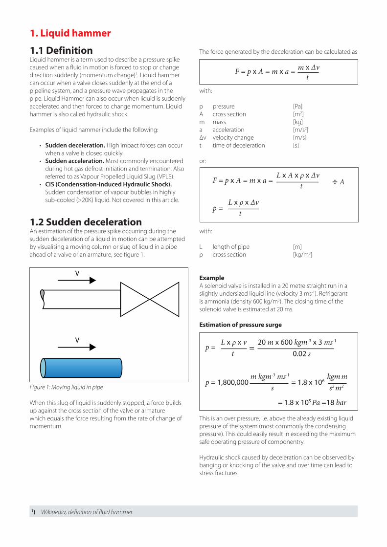
1.2 Sudden decelerationAn estimation of the pressure spike occurring during the sudden deceleration of a liquid in motion can be attempted by visualising a moving column or slug of liquid in a pipe ahead of a valve or an armature, see figure 1.
When this slug of liquid is suddenly stopped, a force builds up against the cross section of the valve or armature which equals the force resulting from the rate of change of momentum.
V
V
Figure 1: Moving liquid in pipe
The force generated by the deceleration can be calculated as
with:
p pressure [Pa]A cross section [m2]m mass [kg]a acceleration [m/s2]Δv velocity change [m/s]t time of deceleration [s]
or:
with:
L length of pipe [m]ρ cross section [kg/m3]
ExampleA solenoid valve is installed in a 20 metre straight run in a slightly undersized liquid line (velocity 3 ms-1). Refrigerant is ammonia (density 600 kg/m3). The closing time of the solenoid valve is estimated at 20 ms.
Estimation of pressure surge
This is an over pressure, i.e. above the already existing liquid pressure of the system (most commonly the condensing pressure). This could easily result in exceeding the maximum safe operating pressure of componentry.
Hydraulic shock caused by deceleration can be observed by banging or knocking of the valve and over time can lead to stress fractures.
1) Wikipedia, definition of fluid hammer.
F = p x A = m x a =t
m x Δv
F = p x A = m x a =t
L x A x ρ x Δv
p = t
L x ρ x Δv
÷ A
p = = t
L x ρ x v 20 m x 600 kgm-3 x 3 ms-1
0.02 s
p = 1,800,000 = 1.8 x 106
= 1.8 x 10⁵ Pa =18 bar
m kgm-3 ms-1 kgm ms s2 m2

In order to minimise the internal volume of liquid line valve stations, the use of compact valve stations designed for high pressure applications such as the Danfoss ICF should be considered (see figure 5).
Figure 5: Danfoss ICF Valves Station
1.3 Sudden acceleration Accelerated liquid often occurs when high pressure vapour meets low to medium pressure liquid. When the accelerated liquid meets an obstruction, which in turn results in a change of momentum, pressure spikes much higher than those caused by decelerated liquid occur.
This is called Vapour Propelled Liquid Slugging (VPLS). VPLS can be classified into two forms of liquid slugs: static and dynamic2.
A static slug is liquid trapped in a portion of the piping, completely filling it. A dynamic slug is a front of liquid, propelled by vapour. In a 6” pipe, as little as 1 ½” of liquid can lead to a dynamic slug, see figure 6.
Static
Figure 6: Static and dynamic liquid slugging
Dynamic
RecommendationsIf the solenoid valve is installed in a HP liquid line (e.g. feed line into a LP vessel) and is not pilot operated, the closing time will be rather short, due to the high pressure differential across the valve.
Therefore, one should consider a proportional liquid level control with a motorised valve, see figure 2.
Excessive pipe runs between solenoid valve and metering device (hand regulating valve) should be avoided for overfeed evaporators. When the solenoid valve is activated, the sudden inrush of liquid can cause hammering at the hand regulating valve, see figure 3.
Figure 3: Avoid excessive pipe runs
It should also be ensured that all liquid line valve stations are sized correctly by taking into consideration the overfeed ratio. An oversized liquid feed valve can lead to excessive liquid velocity. During commissioning, care must be taken that all regulating valves are adjusted correctly. A wide open regulating valve can also cause excessive velocity, see figure 4.
Figure 4: Effect of oversized liquid feed valves
M
Figure 2: Motorised valve for liquid level control
2) Shelton and Jacobi et altera, 1997

2. Hot gas defrost and VPLS The root cause of VPLS is often an incorrectly designed and operated hot gas defrost system. For example, if the hot gas defrost pressure is controlled by a multi-purpose valve in the wet return line, and the hot gas is therefore injected into the bottom of the evaporator coil, there will be a high risk of accelerated liquid.Also, if a single step solenoid valve is used in the wet return line, there will be a sudden pressure equalisation after defrost termination. This can also lead to accelerated liquid. As the velocities are much higher than in the previous example for decelerated liquid, pressure spikes of up to 250 bar can occur, see figure 7.
Figure 7: Commonly designed hot gas defrost system (not recommended)
Operation Liquid Wet return Hot gas Fan Timer
[s] Comment
Cooling Open Open Closed On N/A Controlled by thermostat
Defrost start
Closed Open Closed On 120 – 600 Pump down time depending on evporator size
Closed Closing Closed Off 45 – 200 Closing time for hot gas powered suction valve - ICLX
Closed Closed Closed Off 10 – 20 Allowing remaining liquid to settle at bottom of evaporator
Defrost Closed Closed Open Off 1200 – 1800 Depends on application
Defrost stop
Closed Closed Closed Off 60 – 180 Drip time
Closed Open Closed Off 90 – 300 Suction valve opens slowly. Static cooling to freeze droplets
Open Open Closed Off 60 – 90 Static cooling to freeze droplets
Cooling Open Open Closed On N/A Controlled by thermostat
Table 1: Safe and efficient hot gas defrost sequence
In the correctly designed hot gas defrost system, the hot gas is introduced into the evaporator during defrost from the top, thus eliminating the risk of accelerated liquid at defrost initiation. The defrost pressure is controlled by a separate pressure control valve, enabling a purpose designed two-step solenoid valve with minimal pressure drop (usually hot gas powered) to be used in the wet return line. These valves are available on the market today (e.g. Danfoss ICLX). See figure 8.
NC NO
Figure 8: Moving liquid in pipe

3. Piping design and layoutASME3 code for pressure piping stipulates that “consideration must be given to the expansion of liquid refrigerant trapped in or between closed valves and a means must be provided to prevent over pressure”. Examples of such occurrences are shown in figure 9, e.g. liquid trapped between two shut-off valves, between a non-return valve and a solenoid valve or even between a non-return valve and a back pressure dependent regulator. In all these cases, suitable measure to prevent over pressure (such as relief valves) must be used.
Figure 9: Examples of trapped liquid
4. SummaryIn conclusion, it must be said that when introducing automatic controls for systems previously controlled by manual means, it is imperative to select the correct components for the purpose at hand, integrate these components in a safe way into properly designed industrial refrigeration systems and operate them in an efficient safe way to obtain optimum results.

DKRCI.EE.000.F2.02 | 520H10622 © Danfoss | DCS (jk) | 2016.01
Danfoss can accept no responsibility for possible errors in catalogues, brochures and other printed material. Danfoss reserves the right to alter its products without notice. This also applies to products already on order provided that such alterations can be made without subsequential changes being necessary in speci�cations already agreed.All trademarks in this material are property of the respective companies. Danfoss and the Danfoss logotype are trademarks of Danfoss A/S. All rights reserved.
To read more about industrial refrigeration, please visit ir.danfoss.comFor questions, please contact your local Danfoss industrial refrigeration specialist.
We engineer technologies that enable the world of tomorrow to do more with less
80+ yearsThe industry’s widest expertise at your disposal. We’ve been looking ahead since 1933