fcd decentral solutions design guide mg.90.f2.02
TRANSCRIPT

7/22/2019 FCD Decentral Solutions Design Guide MG.90.F2.02
http://slidepdf.com/reader/full/fcd-decentral-solutions-design-guide-mg90f202 1/191
FCD 300
Design Guide
Decentral SolutionsDMS 300

7/22/2019 FCD Decentral Solutions Design Guide MG.90.F2.02
http://slidepdf.com/reader/full/fcd-decentral-solutions-design-guide-mg90f202 2/191
Decentral Solutions - Des
■ Contents
The decentral concept .............................................
Introduction ........................................................................
Decentral Design Benefits ..................................................
Application Examples .........................................................
Product Design Guide ........................................................
Ordering form - DMS 300 ...................................................
Ordering form - FCD 300 ....................................................
PC Software tools ..............................................................
Accessories for DMS 300 and FCD 300 .............................
Communication ..................................................................
Good Installation Practice ...................................................
Servicing the Danfoss Decentral Products ..........................
Introduction, DMS 300 ..............................................
Operating instructions ........................................................Symbols used in this manual ..............................................
General warning .................................................................
Safety regulations ...............................................................
Warning against unintended start .......................................
Avoiding DMS damage .......................................................
Mechanical details, DMS 300 ................................
Description ........................................................................
General layout ...................................................................
Construction .....................................................................
Tools required ....................................................................
Wall mounting ...................................................................
Motor mounting .................................................................
Ventilation ..........................................................................
Electrical connections, DMS 300 ........................
Power Wiring ......................................................................
Power factor correction ......................................................
Control Wiring ....................................................................
Motor thermistors ...............................................................
S i l i ti

7/22/2019 FCD Decentral Solutions Design Guide MG.90.F2.02
http://slidepdf.com/reader/full/fcd-decentral-solutions-design-guide-mg90f202 3/191
Decentral Solutions - Des
Operation details, DMS 300 ...................................
Operation ...........................................................................Powering-up the DMS ........................................................
Starting the motor: .............................................................
Brake Release ....................................................................
Operation with AS-i Interface .............................................
Description of AS-i profiles used with DMS ........................
Fault Procedure .................................................................
Reading the "Alarm" LED ..................................................
Specification and order codes, DMS 300 .......
General Technical Data ......................................................
Current Ratings (AC53a ratings) .........................................
Ordering type code ............................................................
Certifications ......................................................................
Fuses .................................................................................
Special variants: .................................................................
Motor connection ...............................................................
Details of Profibus Connectivity ..........................................
Profibus DP Slave 6 E/DC 24 V, 4 A/DC 24 V/1A ...............
Table of bits in control and status word ..............................
Profibus connector PCB 4 x M12 .......................................
Profibus address setting: DIP switch SW3 ..........................
Introduction to FCD 300 ..........................................Software version .................................................................
High voltage warning ..........................................................
These rules concern your safety .........................................
Warning against unintended start .......................................
Technology .........................................................................
CE labelling .......................................................................
Installation, FCD 300 .................................................
Mechanical dimensions ......................................................
Mechanical dimensions, FCD, motor mounting ..................
Mechanical dimensions, stand alone mounting ...................
Mechanical installation ........................................................
General information about electrical installation .................
7/22/2019 FCD Decentral Solutions Design Guide MG.90.F2.02
http://slidepdf.com/reader/full/fcd-decentral-solutions-design-guide-mg90f202 4/191
Decentral Solutions - Des
Brake resistor .....................................................................
Control of mechanical brake ...............................................Electrical installation, control cables ....................................
Connection of sensors to M12 plugs for T73 ......................
Electrical installation, control terminals ................................
PC communication .............................................................
Relay connection ................................................................
Connection examples .........................................................
Programming, FCD 300 ...........................................
The LCP 2 control unit, option ............................................
Parameter selection ............................................................
Operation & Display ............................................................
Setup configuration ............................................................
Load and Motor .................................................................
DC Braking ........................................................................
Motortype, par, 147 - FCD 300 ..........................................
References & Limits ............................................................
Handling of references ........................................................
Reference function .............................................................
Inputs and outputs .............................................................
Special functions ................................................................
PID functions ......................................................................
Handling of feedback .........................................................
Serial communication for FCD 300 .....................................
Control Word according to FC protocol ..............................
Status Word according to FC Profile ...................................
Control word according to Fieldbus Profile .........................
Status word according to Profidrive protocol ......................
Serial communication .........................................................
Technical functions .............................................................
All About FCD 300 ......................................................Dynamic braking ................................................................
Internal Brake Resistor .......................................................
Special conditions ..............................................................
Galvanic isolation (PELV) .....................................................
Earth leakage current and RCD relays ................................
E t ti diti

7/22/2019 FCD Decentral Solutions Design Guide MG.90.F2.02
http://slidepdf.com/reader/full/fcd-decentral-solutions-design-guide-mg90f202 5/191
Decentral Solutions - Des
Immunity test result according to Generic standards, PDS pr
standards ........................................................................... Aggressive environments ....................................................
Cleaning .............................................................................
Status messages ................................................................
Warnings/alarm messages .................................................
Warning words, extended status words and alarm words ...
General technical data ........................................................
Technical data, mains supply 3 x 380 - 480 V .....................
Available literature ...............................................................Supplied with the unit .........................................................
Factory Settings .................................................................

7/22/2019 FCD Decentral Solutions Design Guide MG.90.F2.02
http://slidepdf.com/reader/full/fcd-decentral-solutions-design-guide-mg90f202 6/191
Decentral Solutions - Des
■ Introduction
Danfoss was the world’s first company to manufactureand supply frequency converters for infinitely variable
speed control of three-phase AC motors. Until then,
AC motors had to operate at the speed determined
by the frequency of the main power supply.
Production of frequency converters started in 1968.
The f irst frequency converter was also the first
decentralised drive as it was placed next to the motor.
The first frequency converter was total ly enclosed and
filled with silicone oil for cooling, as semiconductors
of that time were very inefficient. The enclosure
design was made for mounting the drive directly in the
application next to the motor. Temperature, water,
cleaning agents, dust and other environmental factors
were also no problem, even in harsh environments.
Semiconductors improved during the next decades.
Air-cooling showed sufficient and oil cooling was
abandoned. At the same time use of frequency
converters grew significantly. PLCs gained a footing for
advanced application control and it became common
practice to install all frequency converters in one
cabinet, rather than several places in the factory.
Continuing improvements in semi-conductors and
related technologies - such as fieldbus technology
- now again makes it feasible to consider installing
drives close to the motors, achieving the benefits of
decentralised installation without the disadvantages
from the first oil-filled frequency converters.
Development of automation in industry is based on the
ability to send and receive data from the applicationneeded to control the processes. More and more
sensors are installed and more and more data is
submitted to the central PLC control. This trend
depends on increased use of fieldbus systems.
I d i l f l i th t t 30 % f
Finally we have included co
about the Danfoss decentr

7/22/2019 FCD Decentral Solutions Design Guide MG.90.F2.02
http://slidepdf.com/reader/full/fcd-decentral-solutions-design-guide-mg90f202 7/191
Decentral Solutions - Des
■Decentralised design benefits
In the following we will concentrate on describingdecentralised installation of frequency converters and
motor starters, referred to here as motor controls.
There are two topologic concepts for the layout of motor
control installations in a plant, in the following referred
to as "centralised" and "decentralised" installations.
The two typologies are illustrated in the figure.
In a centralised installation:
- motor controls are placed in a central place
In a decentralised installation:
- motor controls are distributed throughout the plant,
mounted on or next to the motor they control
Decentralised does not mean "control cabinet free", butmerely that their enormous size can now be reduced
thanks to innovative designs of the components that
will be placed decentralised. There will continue
to be a need for cabinets for power distribution
and for overall intelligence, and there are areas,
particularly in the process industry with areas such
as explosion protection, where centralised cabinets
continue to be the preferred solution.
Placing the advanced and r
to ensure a smooth, respo
operation of the motor next
facilitates modularisation an
and EMC problems dramat
Space-consuming moto
rows of centralised pane
• Reduced efforts for buil
screened motor cables on EMC terminations is
• Heat dissipation from po
from the panel into the
• Standardised machine e
reduces design time and
• Commissioning is easie
Decentralised motor controground despite of the adva
centralised control concept
• no need for extra space
or close to the motor
• no control cable wiring
• independence of plant e
■Direct cost savings
Motor controls for decentra
built to meet the harsh con
areas - especially such con
and beverage industry, whe
are required. This of course
the drive. This increase will
savings in expenses for cab
The cable saving potential
demonstrated by the follow
The figure illustrates an ins
distributed in a number of r
each as is the situation in f

7/22/2019 FCD Decentral Solutions Design Guide MG.90.F2.02
http://slidepdf.com/reader/full/fcd-decentral-solutions-design-guide-mg90f202 8/191
Decentral Solutions - Des
Centralised installation
The drives are distributed equidistant with the distance
L between each drive and the distance h between each
row and also with a distance h from the centralised
power entry/cabinet location to the first row. There
are n rows and N drives in each row
7/22/2019 FCD Decentral Solutions Design Guide MG.90.F2.02
http://slidepdf.com/reader/full/fcd-decentral-solutions-design-guide-mg90f202 9/191
Decentral Solutions - Des
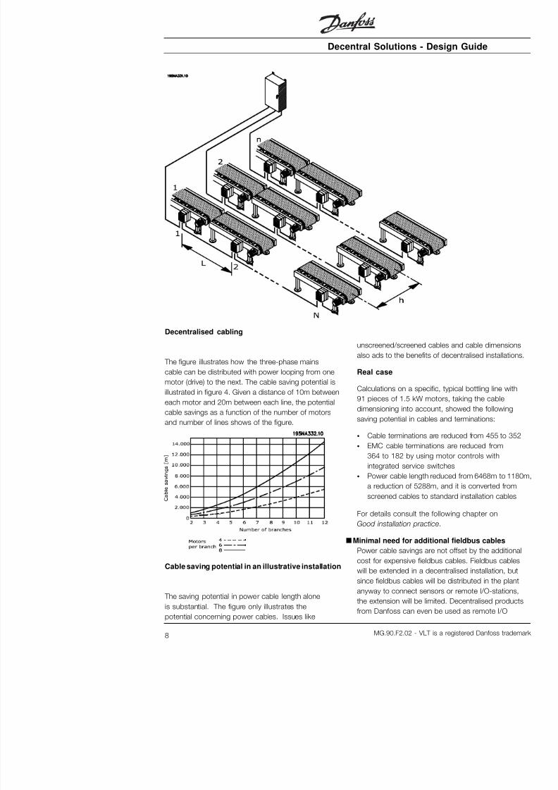
Decentralised cabling
The figure illustrates how the three-phase mains
cable can be distributed with power looping from one
motor (drive) to the next. The cable saving potential is
illustrated in figure 4. Given a distance of 10m between
each motor and 20m between each line, the potential
cable savings as a function of the number of motors
and number of lines shows of the figure.
unscreened/screened cable
also ads to the benefits of d
Real case
Calculations on a specific,
91 pieces of 1.5 kW motor
dimensioning into account,saving potential in cables a
• Cable terminations are r
• EMC cable terminations
364 to 182 by using mo

7/22/2019 FCD Decentral Solutions Design Guide MG.90.F2.02
http://slidepdf.com/reader/full/fcd-decentral-solutions-design-guide-mg90f202 10/191
Decentral Solutions - Des
stations to connect sensors to the fieldbus and
reduce direct costs even more.
Fewer cabinets, cooling and cabletrays
Further savings will result from smaller cabinets, less
cabinet cooling and fewer cable trays. Motor controls
generate heat and are often mounted side by side
due to limited space, as illustrated in Figure 6. Forced
cooling is therefore required to remove the heat.
Less Commissioning
Time spend commissioning at the end-user is
significantly reduced using decentralised solutions -
especially when fieldbus communication is combined
with decentralised motor controls.
Decentralised brewery installation
An Australian brewery has installed a line of 96
decentralised drives from Danfoss connected by
DeviceNet. An excessive amount of time was saved
as the commissioning of the variable speed drives
was done in a few days The brewery estimates
The concept of modularisa
equipment like PC’s and c
well-described functionalitie
used in these products. Th
be applied to manufacturin
physical constraints play a
Production equipment is oft
building blocks, each kind e
in the installation. Examplesconveyor sections and mac
fillers, labellers, palletisers,
Centralised cabinet
In a truly modular machine
self-confined and need noth
compressed air or similar t
Modularisation therefore req
intelligence to the individual
S t li d i t ll ti

7/22/2019 FCD Decentral Solutions Design Guide MG.90.F2.02
http://slidepdf.com/reader/full/fcd-decentral-solutions-design-guide-mg90f202 11/191
Decentral Solutions - Des
installations reduces both time and risk as wiring for
motor, control and sensors are already in place andmaintained during transportation. The need for highly
skilled experts is reduced and local labour can do a
larger part of the installation. The commissioning costs
and OEM resources on-site will be reduced.
■ Improved EMC
Electrical noise emitted is proportional to cable
length. The very short - or eliminated - cable
between motor control and motor in decentralised
installations therefore reduces emitted electrical noise.
In decentralised installations, the machine builder
normally mounts cables between motor controls and
motors in the machine leaving only power cables
and fieldbus cables with no EMC emission to be
installed at the production site. The risk of electrical
noise from motor controls to disturb other electrical
equipment caused by a faulty installation will diminish
and you avoid time-consuming fault finding in the
commissioning phase, where time frame is tight.
■Adapts to standard and special motors
Danfoss’ decentralised motor controls, FCD 300
and DMS 300, are designed to control standard AC
asynchronous motors. Their flexibility allows them
also to adapt to special motor types. An exampleis the AMT feature (Automatic Motor Tuning) in the
FCD 300. Combining Danfoss frequency converters
to Danfoss geared motors makes it even easier
as they fit mechanically and the motor data are
already stored in the FCD 300 memory. Combined
motor-drives are provided pre-assembled directly
from Danfoss removing the need for mechanical
fitting between motor and control.
motor are similar or less tha
connected to mains. Thermand overheat is prevented.
VVC principle ensures nom
speed and eliminates beari
Slim DC-links
It takes two steps to conve
the speed of an AC motor:
As the rectifier itself produca capacitor is often introdu
voltage supplied to the inve
rectifier and inverter with on
even out the voltage is calle
a slim DC link, the inverter w
quite the same voltage amp
mains supply, leading to low
pulse-width-modulation canthe ripple from a slim DC lin
voltage for the motor still d
supply voltage value leading
of motor current up to 10%
motor heating. Low efficien
motor is the result. As torq
square of voltage the applic
sensible to load-changes anrequired. At start, only nom
Principle of a frequency
a DC link coil

7/22/2019 FCD Decentral Solutions Design Guide MG.90.F2.02
http://slidepdf.com/reader/full/fcd-decentral-solutions-design-guide-mg90f202 12/191
Decentral Solutions - Des
Danfoss’ aim is to provide high efficiency drives that
also improve the efficiency of the motors. There
should be no need of expensive over-dimensioning
and inefficient operation.
■Environmental considerations
Drives – both centrally-mounted and distributed in the
plant - are exposed to the environment. As motor
controls handle high voltages and currents at the
same time they must be protected from dust andhumidity so that they do not fail or break down. Both
manufacturers and installers must take account of this
and Danfoss Drives have designed the decentralised
products with a deep concern in both aspects.
Decentralised motor controls must also meet increasing
demands in respect of hygiene levels in pharmaceutical
industries and in food- and beverage production
in particular, where drives are exposed to cleaning
agents for extensive periods of time, high pressure
hosing and the like. The exterior of the decentralised
motor controls must be designed in such a way as
to achieve this. Complicated heat sinks as illustrated
in the figure must be avoided as it is difficult to clean
and not resistant to common cleaning agents.
Danfoss decentralised drives are designed to meetthe requirements as shown in Figure 9. There
are no hard-to-clean places, blind plugs have no
notches or indentations and two-layer robust surface
treatment - tested to withstand commonly used
cleaning agents - protects the housing.
of aseptic geared motors. T
and only smooth surfaces. standard as is the special C
acid, alkali and cleaning ag
food and beverage industry
example of the aseptic gea
Aseptic Danfoss geared
Electrical contact can cause
wet or humid conditions. Thousing (Aluminium) and sc
possible consequence is th
and therefore impossible to
situation. Galvanic corrosio
Danfoss decentralised prod
are fully coated and nylon
the screws protects the co
coating and the unique gascorrosion, which can occur
Tightly enclosed equipment
build-up inside the enclosu
the case where equipment

7/22/2019 FCD Decentral Solutions Design Guide MG.90.F2.02
http://slidepdf.com/reader/full/fcd-decentral-solutions-design-guide-mg90f202 13/191
Decentral Solutions - Des
The pumping effect in tight enclosures
Build-up of water inside enclosures can be prevented
by membranes that prevents fluids to penetrate but
allows for vapour to pass, as known from fabrics
used for outdoor clothing. A special cable gland
with this kind of material is offered by Danfoss to
eliminate this problem. The cable gland should be
used in applications exposed to frequent temperature
fluctuations and humid environments as in equipmentused only during daytime where the inside temperature
tends to fall to theambient temperature during the night.
■ Installation flexibility
Danfoss decentralised solutions offers exceptional
installation flexibility. Flexibility is supported
by a number of benefits:
• Mountable on Danfoss geared motors• Decentralised panel mounting possible
• Handheld control panels
• PC software for configuring and logging
• Single or double sided installation
• Service switch optional

7/22/2019 FCD Decentral Solutions Design Guide MG.90.F2.02
http://slidepdf.com/reader/full/fcd-decentral-solutions-design-guide-mg90f202 14/191
Decentral Solutions - Des
■Application Examples
Danfoss has completed a wide range of applications
in many different industries. This has given us a
valuable experience that has influenced the latest
development of our decent
the following we provide illuactual installations using Da
products, and the benefit a
for the customer in these in
■Beverage - Bottling line

7/22/2019 FCD Decentral Solutions Design Guide MG.90.F2.02
http://slidepdf.com/reader/full/fcd-decentral-solutions-design-guide-mg90f202 15/191
Decentral Solutions - Des
■Beverage - Packaging machine
Decentral motor controls integrated in packaging machine
Benefits:
• Distributing motor controls in the application releases
space for other purposes in the switchboard
• The number of drives in an application can be
increased without extending the switchboard
• IP66 enclosure, easy to clean and resistant
to strong cleaning liquids
• Same flexibility as with centrally mounted
motor controls. Decentralised motor controls
can be adapted for all standard AC motors,
and feature same user interface and same
numbers on connectors
• Profibus integrated

7/22/2019 FCD Decentral Solutions Design Guide MG.90.F2.02
http://slidepdf.com/reader/full/fcd-decentral-solutions-design-guide-mg90f202 16/191
Decentral Solutions - Des
■Food - Cocoa powder plant
Old solution: Motor control - panel mounted decentrally

7/22/2019 FCD Decentral Solutions Design Guide MG.90.F2.02
http://slidepdf.com/reader/full/fcd-decentral-solutions-design-guide-mg90f202 17/191
Decentral Solutions - Des
■Food conveyor

7/22/2019 FCD Decentral Solutions Design Guide MG.90.F2.02
http://slidepdf.com/reader/full/fcd-decentral-solutions-design-guide-mg90f202 18/191
Decentral Solutions - Des
■Automotive Industry - Hoists and conveyors Benefits:
• Simple installation
• AS-i or Profibus control
• Sensor input available w
size of the unit
• Separate 24V supply fo
• Brake supply and contr
• Easy pluggable remote
• Connectors for looping
in the installation box
• Low installation and com
• No additional and expe
connectors needed
• Compact and space sa
• Easy to install and com
• Input for motor thermist

7/22/2019 FCD Decentral Solutions Design Guide MG.90.F2.02
http://slidepdf.com/reader/full/fcd-decentral-solutions-design-guide-mg90f202 19/191
Decentral Solutions - Des
■Retrofit in existing applications
Retrofitting on existing application with speed control
Benefits:
• No need for a big control cabinet thanks to
the decentralised motor controls.

7/22/2019 FCD Decentral Solutions Design Guide MG.90.F2.02
http://slidepdf.com/reader/full/fcd-decentral-solutions-design-guide-mg90f202 20/191
Decentral Solutions - Des
■The decentralised product range
The Danfoss decentralised concept coversmotor controls ranging from motor starters/soft
starters to frequency converters.
Motor starters and soft starters (DMS 300) make
start and stop of your application smoother and
smarter than ordinary DOL (Direct On Line) operation
but do not affect operation further.
Frequency converters (FCD 300) are used forfollowing requirements:
• Adjustable speed
• Precise speed
• Defined speed ramps at start or/and stop
• Shorter stop times (braking)
Danfoss decentralised motor controls range from
0.18 kW to 3 kW (connects to up to 4 kW and
5 HP motors). This chapter lists several optional
features and accessories available.
■Flexible installation options
Danfoss decentralised motor controls FCD 300 and
DMS 300 series can be adapted for mounting using the
following options - each offering specific benefits:
1. Stand alone close to the motor ("wall-mounted")
2. Mounted directly on th
• Fair choice of motor bra
• No need for screened m
3. "Pre-mounted" on Da
geared motors
• A fixed combination of m
supplied by one supplie
• Easy mounting, only on
• No need for screened m
• Clear responsibility rega
As the electronic parts are c
of terminals, similar operati
and spare parts for all driv
mix the three mounting co

7/22/2019 FCD Decentral Solutions Design Guide MG.90.F2.02
http://slidepdf.com/reader/full/fcd-decentral-solutions-design-guide-mg90f202 21/191
Decentral Solutions - Des
■Configuring a product
The decentralised motor controls DMS 300 andFCD 300 series are configured with a type code
string ( see also Ordering ):
DMS 330 P T4 P66 XX D0 Fxx Txx C0
FCD 3xx P T4 P66 R1 XX Dx Fxx Txx C0
Mains voltage
DMS 300/FCD 300 are available for connection to
mains voltage 3 phase 380-480 V.
Choice of motor starter
The motor starter DMS 300 covers the whole power
range from 0.18-3 kW in one unit.
Choice of frequency converter
The frequency converter must be chosen on the
basis of the present motor current at maximum
loading of the unit. The frequency converter’s ratedoutput current IINV. must be equal to or greater
than the required motor current.
Typical shaft output
PINV.
Type [kW] [HP]303 0.37 0.50305 0.55 0.75307 0.75 1.0311 1.1 1.5315 1.5 2.0322 2.2 3.0330 3.0 4.0335** 3.3 5.0*
* at mains/motor voltage 3 x 460 - 480 V
** tamb max. 35° C
■Enclosure
DMS 300 / FCD 300 units are protected against
water and dust as standard.
S l th ti titl d T h i l d t
■24 V external supply
Back up of control supply available in EX and EB vers
■RFI filter
FCD 300 has an integral 1A
1A RFI filter complies with
55011-1A. See the section
Cross section for further de
■Harmonic filter
The harmonic currents do
consumption directly, but th
in the installation (transform
a system with a relatively hi
load it is important to keep
a low level so as to avoid a
high cable temperature. Fo
low harmonic currents, the
with coils in their intermedia
reduces the input current IR
■Display unit
On the FCD 300 unit there
voltage (ON), warning, alarm
In addition, a plug for conn
panel is available as an opt
panel can be installed up to
the frequency converter, e.
by means of a mounting k
All displays of data are via
display, which in normal op
4 operating data items and
continuously. During progra
required for quick efficient

7/22/2019 FCD Decentral Solutions Design Guide MG.90.F2.02
http://slidepdf.com/reader/full/fcd-decentral-solutions-design-guide-mg90f202 22/191
Decentral Solutions - Des
■ Installation box variants
Connections on right sideGland holes for all cable inlets are machined on the
right side only (seen from motor drive end). This
version is useful where cable inlet is required from
one direction only (only FCD 300 series).
Connections on two sides
Gland holes for cable inlets are machined on both sides
allowing for cable inlet from both directions.
Both metric thread and NPT thread is available
(selected variants).
Pluggable connection and the possibility of looping
mains power supply between drives (4 mm2 line).
The bottom section contains Cage Clamp connectors
and looping facilities for power and fieldbus cables wellprotected against dust, hosing and cleaning agents.
Service switch mounted on the right side (seen from
motor drive end). A lockable switch integrated in the
enclosure – disconnecting the motor or drive.
4 sensor plugs, M12 on the right side (seen from motor
drive end). Looping through of 2 X 24 V external supply.
Pluggable connection of remote I/O such as sensorsand external supply of these.
Motor plug, HARTING 10 E on the right side (seen
from motor drive end) wired according to DESINA
standard ( see electrical installation ).
Display connector for external pluggable connection
of the local control panel for operating and
programming. Can also be used for PC connection.
Only available for FCD 300.

7/22/2019 FCD Decentral Solutions Design Guide MG.90.F2.02
http://slidepdf.com/reader/full/fcd-decentral-solutions-design-guide-mg90f202 23/191
Decentral Solutions - Des
■DMS 300 Decentralised electronic Motor Starter
DMS 300 - Combinations of versions
Installation features
Mounting Motor Wall Motor Wall Motor WallPluggable - X Service switch - - - - X XSensor plugs - - - - - -
Motor plug - - - - - -
Ordering codes DMS 330 P T4 P66 XX D0 Fxx Txx C0Metric thread
(NPT thread)
T10 T50 T12
(T16)*
T52
(T56)*
T22
(T26)*
T62
(T66)*Functional features
Basic functions(see below)
ST
+ Brake control SB
-
+ Current
monitoring
EX
+ Current
monitoring +
Brake control
EB
+ Current
monitoring +Brake control +
Reversing
-
ER
CommunicationNo bus F00
AS-interface - F70 Profibus - F12*
- = not available * contact Danfoss sale
Basic functions
Electronic start/stop of a motor
Soft start/stop
Extended functionality

7/22/2019 FCD Decentral Solutions Design Guide MG.90.F2.02
http://slidepdf.com/reader/full/fcd-decentral-solutions-design-guide-mg90f202 24/191
Decentral Solutions - Des
■Ordering form - DMS 300
7/22/2019 FCD Decentral Solutions Design Guide MG.90.F2.02
http://slidepdf.com/reader/full/fcd-decentral-solutions-design-guide-mg90f202 25/191
Decentral Solutions - Des
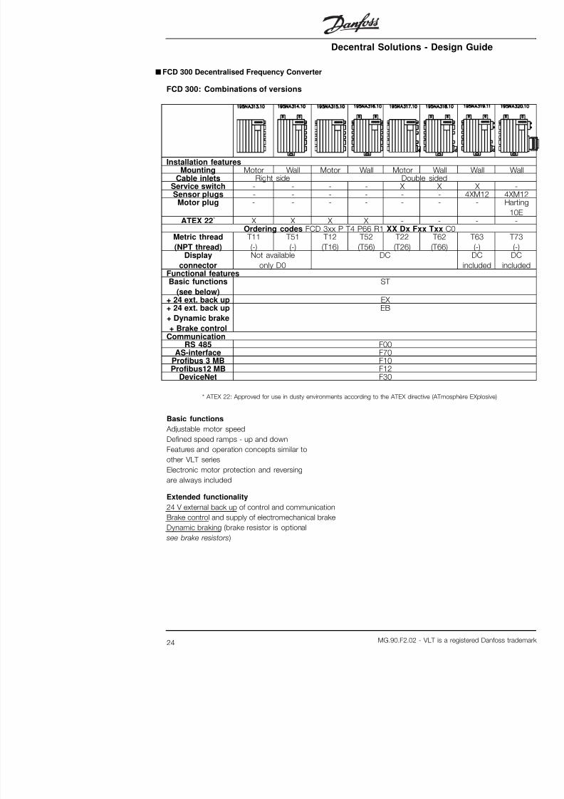
■FCD 300 Decentralised Frequency Converter
FCD 300: Combinations of versions
Installation features
Mounting Motor Wall Motor Wall Motor WallCable inlets Right side Double sided
Service switch - - - - X XSensor plugs - - - - - -
Motor plug - - - - - -
ATEX 22* X X X X - - Ordering codes FCD 3xx P T4 P66 R1 XX Dx Fxx Txx C
Metric thread
(NPT thread)
T11
(-)
T51
(-)
T12
(T16)
T52
(T56)
T22
(T26)
T62
(T66)Display
connector
Not available
only D0
DC
Functional featuresBasic functions
(see below)
ST
+ 24 ext. back up EX + 24 ext. back up
+ Dynamic brake
+ Brake control
EB
CommunicationRS 485 F00
AS-interface F70Profibus 3 MB F10Profibus12 MB F12
DeviceNet F30
* ATEX 22: Approved for use in dusty environments according to the ATEX directive (ATmo
Basic functions
Adjustable motor speed
Defined speed ramps - up and down
Features and operation concepts similar to
other VLT series

7/22/2019 FCD Decentral Solutions Design Guide MG.90.F2.02
http://slidepdf.com/reader/full/fcd-decentral-solutions-design-guide-mg90f202 26/191
Decentral Solutions - Des
The below explanations refer to the ordering form.
Power sizes (positions 1-6):0,37 kW – 3,3 kW (See power size selection table)
Application range (position 7):
• P-process
Mains voltage (positions 8-9):
• T4 - 380-480 V three phase supply voltage
Enclosure (positions 10-12):
The enclosure offers protection against dusty,
wet, and aggressive environment
• P66 - Protected IP66 enclosure
Hardware variant (positions 13-14):
• ST - Standard hardware
• EX - 24 V external supply for backup of control card
• EB - 24 V external supply for backup of control
card, control and supply of mechanical brake
and an additional brake chopper
RFI filter (positions 15-16):
• R1 - Compliance with class A1 filter
Display unit (LCP) (positions 17-18):
Connection possibility for display and keypad
• D0 - No pluggable display connector in the unit
• DC - Display connector plug mounted (not available
with "only right side" installation box variants)
Fieldbus option card (positions 19-21): A wide selection of high performance fieldbus
options is available (integrated)
• F00 - No fieldbus option built in
• F10 - Profibus DP V0/V1 3 Mbaud
Installation box (positions 2
• T00 - No Installation bo
• T11 - Installation box, m
thread, only right side
• T12 - Installation box, m
thread, double side
• T16 - Installation box, m
thread, double side
• T22 - Installation box, mthread, double side, ser
• T26 - Installation box, m
double side, service sw
• T51 - Installation box, w
thread, only right side
• T52 - Installation box, w
thread, double side
• T56 - Installation box, wthread, double side
• T62 - Installation box, w
double side, service sw
• T66 - Installation box, w
double side, service sw
• T63 - Installation box, w
double side, service sw
• T73 - Installation box, wdouble side, motor plug
Coating (positions 25-26):
The IP66 enclosure offers p
aggressive environments, w
the need for coated printed
• C0 - Non coated board

7/22/2019 FCD Decentral Solutions Design Guide MG.90.F2.02
http://slidepdf.com/reader/full/fcd-decentral-solutions-design-guide-mg90f202 27/191
Decentral Solutions - Des
■Ordering form - FCD 300

7/22/2019 FCD Decentral Solutions Design Guide MG.90.F2.02
http://slidepdf.com/reader/full/fcd-decentral-solutions-design-guide-mg90f202 28/191
Decentral Solutions - Des
■PC Software tools
PC Software - MCT 10
All drives are equipped with a serial communication
port. We provide a PC tool for communication
between PC and frequency converter, VLT Motion
Control Tool MCT 10 Set-up Software.
MCT 10 Set-up Software
MCT 10 has been designed as an easy to use interactive
tool for setting parameters in our frequency converters.
The MCT 10 Set-up Software will be useful for:• Planning a communication network off-line. MCT 10
contains a complete frequency converter database
• Commissioning frequency converters on line
• Saving settings for all frequency converters
• Replacing a drive in a network
• Expanding an existing network
• Future developed drives will be supported
MCT 10 Set-up Software support Profibus DP-V1 via
a Master class 2 connection. It makes it possible to
on line read/write paramete
via the Profibus network. T
for an extra communication
The MCT 10 Set-up Softw
The following modules are
software package:
MCT 10 Set
Setting param
Copy to and
converters
Documentati
parameter se
SyncPos
Creating Syn
Ordering number:Please order your CD cont
Software using code numb
■Accessories for DMS 300 and FCD 300
Type Description
LCP2 control unit FCD LCP2 for programming the frequency cCable for LCP2 control
unit
FCD Cable from LCP2 to frequency convert
LCP2 remote-mounting
kit
FCD Kit for remote-mounting of LCP2 (incl.
cable, excl. LCP2)LOP (Local Operation
Pad)
FCD LOP can be used for setting the referen
and start/stop via the control terminalsMotor adaption plate DMS/FCD Plate for adapting to non Danfoss BaueMembrane DMS/FCD Membrane for preventing condensationPlug kit for LCP2 FCD Plug for LCP2 for mounting in the termMotor star terminal DMS/FCD Terminal for interconnection of motor w
point)Installation kit FCD Installation kit for mounting in panels M 12 plug FCD E.g. for DeviceNet Viton Gasket FCD 303 315 Painting shop compatible

7/22/2019 FCD Decentral Solutions Design Guide MG.90.F2.02
http://slidepdf.com/reader/full/fcd-decentral-solutions-design-guide-mg90f202 29/191
Decentral Solutions - Des
Data cable for PC communication 175N2491
(for the FCD 300 series)connects a converter (e.g. USB) to the LCP2 connector.
Remote mounting kit for LCP2 175N0160
(for the FCD 300 series)
Kit for permanent mounting of the LCP2 in an enclosure.
Venting membrane 175N2116
Membrane preventing water build-up due to
condensation inside enclosures.
Star point terminal 175N2119
Six wires must be either star- or delta-connected to
supply an AC motor. Delta connection is possible
in the standard motor terminal. Star connection
requires a separate terminal.
5 pole M12 plug for e.g. DeviceNet 175N2279
(for the FCD 300 series)
The plug, micro type, M12 can be mounted into the
gland holes of the installation box. The plug can also be
used for other purposes such as connection of sensors.
2m drop cable for DeviceNet 195N3113
(for the FCD 300 series)
The cable can be mounted inside the terminal
box, and connects to the DeviceNet trunk linevia a micro connector (M12).
5 pole M12 plug for AS-in The plug, M12, can be mo
holes of the installation box
Viton Gasket for FCD 30
With this gasket the FCD c
shops in e.g. the automoti
Viton Gasket for FCD 32
With this gasket the FCD c
shops in e.g. the automoti
■Ordering numbers for brake resistors
Internally mountable brake resistors for low duty cycle
braking (1-3%). The resistors are self-protecting.
Internal brake resistors can
FCD 303-315 with service
Type Description Internal brake resistor FCD 303-307 Brake resistor for mounting inside the t
boxInternal brake resistor FCD 311-335 Brake resistor for mounting inside the t
box
Flatpack brake resistors IP 65

7/22/2019 FCD Decentral Solutions Design Guide MG.90.F2.02
http://slidepdf.com/reader/full/fcd-decentral-solutions-design-guide-mg90f202 30/191
Decentral Solutions - Des
Mounting bracket for brake resistors
Type Orde175N
303-315 24
322-335 24
Coiled wire brake resistors Duty-cycle 40%
VLT type Intermit-
tent brak-
ing period
time
[seconds]
Pmotor
[kW]
Rmin
[ ]
Rrec
[ ]
Pb, max
[kW]
Therm.re-
lay
[Amp]
303 (400 V) 120 0,37 520 830 0,45 0,7
305 (400 V) 120 0,55 405 830 0,45 0,7
307 (400 V) 120 0,75 331 620 0,32 0,7
311 (400 V) 120 1,1 243 430 0,85 1,4
315 (400 V) 120 1,5 197 330 0,85 1,6
322 (400 V) 120 2,2 140 220 1,00 2,1
330 (400 V) 120 3,0 104 150 1,35 3,0
335 (400 V) 120 3,3 104 150 1,35 3,0
*Always observe national and local regulations
Pmotor : Rated motor size for VLT type
Rmin : Minimum permissible brake resistor
Rrec : Recommended brake resistor (Danfoss)
Pb, max : Brake resistor rated power as stated by supplier
Therm. relay : Brake current setting of thermal relay
Code number : Order numbers for Danfoss brake resistors
Cable cross section : Recommended minimum value based upon PVC insu
degree Celsius ambient temperature with normal heat d
See dimensions of Coiled wire brake resistors in instructions MI.90.FX.YY
Externally mounted brake resistors in general
No use of aggressive cleaning solvents. Cleaning
solvents must be pH neutral.
See Dynamic braking for dimensioning of

7/22/2019 FCD Decentral Solutions Design Guide MG.90.F2.02
http://slidepdf.com/reader/full/fcd-decentral-solutions-design-guide-mg90f202 31/191
Decentral Solutions - Des
■ Information and communication
Growth in the world of automation is increasingly
based on information technology. Having reformed
hierarchies, structures and flows in the entire office
world, use of information technology opens for a
similar restructuring of industrial sectors ranging
from process and manufacturing industries to
logistics and building automation.
Devices capability of communication and continuous
transparent channels for information are indispensablein automation concepts of the future.
IT is an evident means for optimisation of system
processes, leading to improved exploitation of
energy, materials and investment.
Industrial communication systems are a key
function in this respect.
Cell level
Programmable controllers such as PLC and IPC
communicate at cell level. Large data packets
and numerous powerful communication functions
provide information flow. Smooth integration into
company-wide communication systems, such
as Intranet and Internet via TCP/IP and Ethernet
are important requirements.
Field level
Distributed peripherals such as I/O modules, measuring
transducers, drive units, valves and operator terminals
communicate with the automation systems via an
efficient, real-time communication system at field level.
Transmission of process data is performed in cycles,
while alarms, parameters and diagnostic data have
to be transmitted acyclically if necessary.
Sensor/actuator level
Binary signals from sensors and actuators are
transmitted purely cyclically via bus communication.
More than 2,000 products
Profibus vendors are availa
6.5 million devices represen
products are installed and
more than 500,000 applica
and process automation.
Danfoss Drives solution
optimal Profibus solutio
• MCT-10 software tool fo• Simple two-wire connec
• A universal, globally acc
• Compliance with the int
EN 50170
• Communication speed
• Access to drive master f
• Fulfilment of PROFIDRIV
• Integrated solution• All frequency converters
by the Profibus organis
• Danfoss frequency conv
Profibus DP V1
Profibus DP V1 for two d
Fieldbus systems are used
purposes with two very diff
modern automation applica
signals referring to the proc
commissioning and set-up
Transfer of control and statu
and actuators is time critica
reliably and in real time. Th
cyclic communication wher
is polled within each cycle,pre-defined time. It is nece
minimise the extent of data
this work reliably and as fa
This consideration contradic

7/22/2019 FCD Decentral Solutions Design Guide MG.90.F2.02
http://slidepdf.com/reader/full/fcd-decentral-solutions-design-guide-mg90f202 32/191
Decentral Solutions - Des
in a specified time slot in each cycle. Profibus DP
V1 thus operates with two classes of masters.
Masterclass 1 (typically a PLC) performs the cyclic
communication. Masterclass 2, typically an interface
device (HMI or PC), transfers non-time critical
information through non-cyclic communication.
Masterclass 2 masters can be connected anywhere
on the Profibus net and the communication channel
can be opened and closed anytime without disturbing
the cyclic communication. You can have non-cycliccommunication even without cyclic communication to
for instance transfer complete programs or set-ups.
Profibus DP V1 is fully compatible with prior versions of
Profibus DP V0. Profibus DP V0 and Profibus DP V1
nodes can be combined in the same network, although
the master must support Masterclass 2 communication.
User benefits:
• Connection to the motor controls is possible
from every part of the network
• Existing network can be used for commissioning,
set-up and diagnostic without disturbing of
the cyclic communication
• Both DP V1 and DP V0-nodes can be connected
in the same network • No need for extensive telegrams in the PLC
or IPC. A second master who supports DP
V1 can handle set-up tasks
NB!:
DP V1 is only possible for Master
communication-cards which support
Masterclass 2 specification.
■DeviceNet
DeviceNet is a communications link that connects
industrial devices to a network. It is based on
the broadcast-oriented, communications protocol
• Unconnected Messages
messages are supporte
• Integrated solution
• Electronic Data sheet (E
easy configuring
• Provides fieldbus voltag
• Fulfilment of DeviceNet
• Protocol defined in acco
DeviceNet Vendor Asso
■AS-interface AS-interface (AS-i) is a cos
to conventional cabling at t
automation hierarchy. The
higher-level fieldbus like Pro
I/O. Known by its yellow ca
"open" technology support
vendors worldwide. Enhanc
broadened its field of applictoday proven in hundreds o
and applications spanning t
■ InterBus
InterBus is an open, non-p
It complies with the EN 50
decentralised motor contro
fieldbus communication alloto an InterBus network.
• Easy connection
• Compliance with the int
EN 50254
• I/O based transmission
protocol efficiency
• Unified planning tool (e.
• InterBus option is certif
Frauenhofer Institute
The Gateway IB-S/DP for D
allows for up to 14 frequen
series on the same InterBu

7/22/2019 FCD Decentral Solutions Design Guide MG.90.F2.02
http://slidepdf.com/reader/full/fcd-decentral-solutions-design-guide-mg90f202 33/191
Decentral Solutions - Des
■Good Installation Practice
■Flexible installation options
A major benefit of Danfoss’ decentralised concept
is saving installation cost partly due to the clever
two-part design of the DMS 300/FCD 300.
All electrical installation is done inside the installation
box prior to mounting the electronic part. Subsequently
the electronic part is plugged into the installation box,
fixed, and the drive is ready for operation.
Power line looping
The FCD 300 and DMS 300 series facilitates internal
power line looping. Terminals for 4 mm2 power cables
inside the enclosure allows connection of up to 10+
units. FCD 300 and DMS 3
the line. Average load mus
24 V control back up
External 24 V (20-30 V) DC
in the EX and EB versions
circuits. This way commun
possibility are maintained e
down. The terminals are d
2.5 mm2 and are doubled
The T63 and T73 installatio
looping terminals for 2 X 2
Connected sensors can be
from the control back up s

7/22/2019 FCD Decentral Solutions Design Guide MG.90.F2.02
http://slidepdf.com/reader/full/fcd-decentral-solutions-design-guide-mg90f202 34/191
Decentral Solutions - Des
■Guidelines for selection of cables and fuses in a
power line installation with FCDand DMS products
It is assumed that the installation follows the Low
Voltage Directive as stated in HD 384 and IEC 60364.
This section can’t be used in explosive areas and where
fire hazard exists. In general cable dimension has to
follow IEC 60364-5-523. If the installation is part of a
machinery EN 60204-1 has to be followed. Cables
as mentioned under point 1, 2 and 3 in the figure has
to be protected by an enclosure or conduit.
The following section numbers refer to the figure.
1. The cable shall only be able to carry the maximum
continuous current of the friction brake. By ground
fault non-renewable protective circuit in the FCD
will interrupt the flow of current.
2. If the IP 65 brake resistors recommended by
Danfoss are used the cable will only be exposed
to the continuous current of the brake resistor.If the brake resistor becomes overheated it will
disconnect itself. If another type or make of
brake resistor, without any power limitation device,
is used, the maximum power must be equal
to the rated power of the motor.
The current in Amps would be: I = 0.77/motor
power, with motor power inserted in kW; [A=V/W].
The rated motor current comes fairly close to thecurrent in the cable to the brake resistor.
3. The cables to encoders and thermistors are on
PELV potential. The currents are in mA range
and limited by the FCD or DMS. In order not to
violate the PELV protect
of FCD the thermistor h
insulation according to t
For EMI purposes the c
own electrical shielding
separated from power c
4. The cable is protected b
in the FCD. By ground fa
impedance the FCD will
5. The current is limited by
short circuit protected b
6. The current is limited by
DMS*. The CB makes th
protection. The impeda
be so low that the CB d
impedance ground fault
7. If installation is on a mac
the distance between th
FCD or DMS* is less tha
be downsized to the cu
needed for the down st
8. The trip current for the C
be higher than the highe
the smallest FCD or DM
See section Fuses for DMS
For EMC purposes cable #
shielded or placed in meta
* only extended versions

7/22/2019 FCD Decentral Solutions Design Guide MG.90.F2.02
http://slidepdf.com/reader/full/fcd-decentral-solutions-design-guide-mg90f202 35/191
Decentral Solutions - Des
■Service
Breakdown of Danfoss drives or geared motors only
occur under exceptional circumstances. As downtime
represents lack of production, failures must be located
and defective components replaced quickly.
Danfoss’ decentralised products place great
emphasis on addressing these issues. This chapter
also describes measures taken to make Danfoss
decentralised products superior in a service situation.
For detailed information on specific service issues
please consult relevant literature.
Centralised frequency converters from Danfoss have
pluggable connections to facilitate service using fast
and faultless replacement. The same concept is used
and improved for the decentralised drives.
Plug-and-drive
All the advanced and reliable electronics neededto ensure your motors act smoothly, responsively
and economically at each command are hidden
inside the box lid and plug into connectors when
mounted onto the bottom section. The bottom section
contains maintenance-free Cage Clamp connectors
and looping facilities for power and fieldbus cables
well protected against dust, hosing and cleaning
agents. Once installed, commissioning and upgrading
can be performed in no time simply by plugging in
another control lid. See the illustration.
You only need standard ins
glands, cables, etc., to comDanfoss decentralised drive
hybrid cables not likely to be
supplier of electric installatio
This provides high flexibility

7/22/2019 FCD Decentral Solutions Design Guide MG.90.F2.02
http://slidepdf.com/reader/full/fcd-decentral-solutions-design-guide-mg90f202 36/191
Decentral Solutions - Des
DMS 300 Series

7/22/2019 FCD Decentral Solutions Design Guide MG.90.F2.02
http://slidepdf.com/reader/full/fcd-decentral-solutions-design-guide-mg90f202 37/191
Decentral Solutions - Des
■Operating instructions
DMS Version no.02
These operating instructions can be used for all
DMS 300 units with version no. 02.
The version no. can be identified from the product
serial number. The 5th and 6th digit from left
pertain to the version no.
Thus serial number xxxx-02-xxx indicates
version no. 02.
■Symbols used in this manual
When reading this manual you will come across
different symbols that require special attention.
The symbols used are the following:
NB!:
Indicates something to be noted by the reader
Indicates a general warning
Indicates a high voltage warning
■General warning
The DMS contains dangerous voltages
when connected to line voltage. Only a
competent electrician should carry out the
electrical installation. Improper installation of the motor
or the DMS may cause equipment failure, serious
injury or death. Follow this manual as well as nationaland local rules and safety regulations.
■Safety regulations
1. The DMS must be disco
if repair work is to be ca
2. The [COASTING STOP
applied to the DMS doe
equipment from the ma
be used as a safety sw
It is the respons
person installinggrounding and b
accordance with national a
■Warning against unintend
1. The motor can be broug
of digital commands, bu
stop, while the DMS is c
personal safety consideto ensure that no uninte
stop functions are not s
2. A motor that has been s
occur in the electronics
■Avoiding DMS damage
Please read and follow all in
Electrostatic Predischarge (ESD)
components are
electricity. Voltages so low
felt, seen or heard, can red
performance, or completely
electronic components. Wh
proper ESD equipment sho
possible damage from occ

7/22/2019 FCD Decentral Solutions Design Guide MG.90.F2.02
http://slidepdf.com/reader/full/fcd-decentral-solutions-design-guide-mg90f202 38/191
Decentral Solutions - Des
■Description
The Danfoss DMS is an advanced electronic motor
starting system. It performs six main functions;
1. Start control, including soft start.
2. Stop control, including soft stop (extended
stop time).
3. Thermistor motor protection
4. Electronic motor protection (optional).
5. Electromechanical brake control (optional)
6. Monitoring & system interface.
■General layout
■Construction
The DMS unit is made of two separable parts:
1. Installation box, which is the bottom half. The
installation box has all the mounting arrangement,
cable entries, and earthing studs.
2. Electronics Module, which is the top half.
The electronics module contains all the
circuitry of the DMS.
■Tools required
The DMS unit does not require any special
tools for installation
Use the nylon washers pro
scratching the protective p
Dimension drawing - DMS
■Motor mounting
1. Remove the cover of m2. In the DMS Installation b
holes to match the moto
Two hole-patterns (4 ho
provided to suit Danfoss
depending on the powe
For different motors use
adaption plate [Order no
3. In the DMS Installation bcable gland (1 of 30 mm
connection to motor ter
4. Mount the DMS Installa
the motor terminal box.
D l S l i D

7/22/2019 FCD Decentral Solutions Design Guide MG.90.F2.02
http://slidepdf.com/reader/full/fcd-decentral-solutions-design-guide-mg90f202 39/191
Decentral Solutions - Des
■Ventilation
DMS cooling is by means of air circulation.
Consequently, the air needs to be able to move
freely above and below the soft starter.
If installing the DMS in a switchboard or other enclosure,
ensure there is sufficient airflow through the enclosure
to limit heat rise in the enclosure to maintain the internal
enclosure temperature at or below 40 deg. C. (Heat
loss of DMS at rated current is 18 watts approx.).
Derating curve for temperature
D t l S l ti D

7/22/2019 FCD Decentral Solutions Design Guide MG.90.F2.02
http://slidepdf.com/reader/full/fcd-decentral-solutions-design-guide-mg90f202 40/191
Decentral Solutions - Des
■Power Wiring
Connect the Supply voltage to the DMS input
terminals 1/L1, 3/L2 & 5/L3.The terminals in the
Extended versions of the DMS allow two cables
to loop the power line as shown.
Looping the power line - 3-phase mains
For ST & SB versions, provand control cables by usin
provided in the DMS unit, a
■Power factor correction
If a DMS is used
correction it mu
supply side of th
Connecting pow
capacitors to the output of
in damage to the DMS.
■Control Wiring
Complete the Control wirin
Electrical Schematic diagra
Decentral Solutions Des

7/22/2019 FCD Decentral Solutions Design Guide MG.90.F2.02
http://slidepdf.com/reader/full/fcd-decentral-solutions-design-guide-mg90f202 41/191
Decentral Solutions - Des
■Motor thermistors
If the motor is fitted with thermistors these may
be connected directly to the DMS. To connect the
thermistors, first remove the shorting link, and then
connect the thermistors between terminals 31A & 31B.
Use double-isolated thermistors to
retain PELV.
■Serial communication The DMS can be equipped with either AS-i or
Profibus communication capabilities.
The AS-i and Profibus interfaces are optional.
The AS-i Fieldbus is connected at terminals 125 & 126.
The details of the Profibus connectivity are given
at the end of the manual.
NB!:
Communications and control cabling should
not be located within 300mm of power
cabling. Where this cannot be avoided
consideration should be given to providing magnetic
shielding to reduce induced common mode voltages,
for example, by laying the communication and
control cables in a separate conduit.
■Earthing
Ensure that the DMS unit is earthed
properly. Use the chassis earth studs
provided for the purpose (4 of size M4).
For type T73 units, an external earth plug
(size M8) is provided to facilitate earthing.
To retain the IP rating of DMS, remember
to close all the unutilized cable entries
using the gland plugs (bungs ) provided
loose with the DMS unit. In units with external plugs,
all plugs must be correctly mounted.
Decentral Solutions - Des

7/22/2019 FCD Decentral Solutions Design Guide MG.90.F2.02
http://slidepdf.com/reader/full/fcd-decentral-solutions-design-guide-mg90f202 42/191
Decentral Solutions - Des
■Electrical Schematic
Decentral Solutions - Des

7/22/2019 FCD Decentral Solutions Design Guide MG.90.F2.02
http://slidepdf.com/reader/full/fcd-decentral-solutions-design-guide-mg90f202 43/191
Decentral Solutions Des
■Adjustment/ Settings
DMS adjustments are made using the DIP switch
adjustment panel located on the underside of the Electronics module.
Section Switch no.Description Value
1
2
3 4
Start/ stop
profile setting
Selection of
ramp times
and start
voltage. Seetable below.
5
A
6 Trip class
selection
See table
below Off
1 Not used2 3.2A 3 1.6A
4 0.8A 5 0.4A
B
6
Full load
current
setting (note:
0.1Amps is
always added
internally)
0.2A
See table
below
Note: Settings marked grey are applicable
only in Extended versions.
■Start/ stop profile setting
Choose the required Start/ Stop profile which is most
suited to the application. Use DIP switches A1-A4 to set
the start/stop profile. Some examples are shown below.
4
20%
40%
60%
80%
Motorvoltage%
Time, sec.
Start stop Profile no: 14
100%
8
[DIP Switch settings
7 Sec. 5 Sec.
Start ramp Stop ramp
2 6
Run
Decentral Solutions - Des

7/22/2019 FCD Decentral Solutions Design Guide MG.90.F2.02
http://slidepdf.com/reader/full/fcd-decentral-solutions-design-guide-mg90f202 44/191
Decentral Solutions Des
■Start/ stop profile setting table:
Start/stop
Profile
Start
Performance
Stop
Performance
1
(A1) 2 (A2) 3 (A3)
4
(A4)
Init
Volt
(%
0 Equivalent to
DOL Coast to stop Off Off Off Off 80
1 Fastest Off Off Off On 80
2 | Off Off On Off 60
3 | Off Off On On 60
4 | Off On Off Off 60
5 | Off On Off On 50
6 | Off On On Off 40
7 | Off On On On 508 | On Off Off Off 60
9 Slowest
Coast to stop
On Off Off On 60
10 Fastest Fastest On Off On Off 60
11 | | On Off On On 50
12 | | On On Off Off 40
13 | | On On Off On 40
14 | | On On On Off 30
15 Slowest Slowest On On On On 30
Note: * indicates Stop Ramp time is not controlled
by DMS. Motor will coast to stop.
# In some applications, act
motor shaft could differ fro
■Trip Class selection: This sett ing is applicable only for the Extended
versions of DMS.
The DMS motor overload protection is an advanced
motor thermal model. Motor temperature is
continuously calculated by the microprocessor
withstand Locked Rotor Cu Trip Class 10 (or lower) in t
If in doubt, use "Trip Class
Default setting for this para
the DMS will trip & protect
Rotor current sustains for m
Decentral Solutions - Des

7/22/2019 FCD Decentral Solutions Design Guide MG.90.F2.02
http://slidepdf.com/reader/full/fcd-decentral-solutions-design-guide-mg90f202 45/191
■Full Load Current setting:
This sett ing is applicable only for the Extended
versions of DMS and refers to the ETR function. Itmay not be used for current limitation.
Calibrate the DMS for the connected motor
nameplate Full Load Current (FLC).
Use the five (5) DIP switche
nameplate FLC minus 0.1 A
internally to the FLC amps. Please note that switch B1
■FLC setting table :
DIP Switch bits Value (Amps) Example-1 for setting
FLC=4.3 Amps
2 (B2) 3.2 On
3 (B3) 1.6 Off
4 (B4) 0.8 On
5 (B5) 0.4 Off 6 (B6) 0.2 On
6.3 Amps, when B2-B6
are all On
0.1+3.2+0+0.8+0+0.2
= 4.3
See remark
Note:0.1 Amps is added internally to the value
read from DIP switches.
■Completing the installation:
To complete installation, fit the DMS Electronics
module to the DMS Installation box and secure with
the screws provided. Recommended tightening torque
for the screws is between 2.5 and 3 Nm.
Decentral Solutions - Des

7/22/2019 FCD Decentral Solutions Design Guide MG.90.F2.02
http://slidepdf.com/reader/full/fcd-decentral-solutions-design-guide-mg90f202 46/191
■Operation
Once the DMS has been installed, wired and
programmed according to the instructions,it can be operated.
■Powering-up the DMS
Power may now be applied to the DMS unit.
The "On" LED should glow when the 24VCD
Control Supply is turned On.
■Starting the motor:
Connect +24VDC to the "Reset/ Coasting
stop inverse input (27).
To start the motor in the Forward direction,
use the Start CW Input (18). To initiate a stop,
open the Start CW Input.
To start the motor in the Reverse direction, use the
Start CCW Input (19).This feature is optional. To
initiate a stop, open the Start CCW Input.
If the direction of rotation is wrong, change any
two of mains or motor phases.
Disconnecting the +24VDC to the "Reset/ Coasting
stop inverse input (27) will disable the DMS and
cause the motor to coast to stop.
NB!:If both Start CW & Start CCW inputs are
active together, the motor will stop.
■Brake Release
(For variants with Braking function only -
variants SB, EB, ER).
When a Start is initiated, the DMS automatically
generates a brake release command. This will releasethe brakes before the motor starts running.
The motor brake can also be released without
starting the motor by connecting +24VDC to
the Brake Release input (124).
■Operation with AS-i Interf
The AS-i switch profile S-7following inputs and output
• Start CW (DO)
• Start CCW (D1)
• Brake Control (D2)
• Reset (D3)
• Ready output(D0)
• Run Output (D1)• Fault Output (D2)
The profile codes with the d
• Profile 7E 1 for Extende
• Profile 7E 3 for Extende
• Profile 7E 4 for Extended
Decentral Solutions - Des

7/22/2019 FCD Decentral Solutions Design Guide MG.90.F2.02
http://slidepdf.com/reader/full/fcd-decentral-solutions-design-guide-mg90f202 47/191
■Description of AS-i profiles used with DMS
Bit Type for host Meaning Host
level
Direct starter
Profile 7E 1
Direct starter wibrake
Profile 7E 3
D0 output Run forward 0
1
Stop - forward
Start - forward
Stop - forward
Start - forward
D1 output Run reverse 0
1 Not used Not used
D2 output Brake 0
1 Not used Motor blocked
Motor free
D3 output Fault reset 0
1
Not reset
Reset
Not reset
Reset
D0 input Ready 0
1
Not ready or fault
Ready
Not ready or fau
Ready
D1 input Running 0
1
Motor stopped
Motor running
Motor stopped
Motor running
D2 input Fault 0
1
No fault
Fault
No fault
Fault
D3 input Not used 0
1 Not used Not used
P0 parameter Not used
P1 parameter Not used
P2 parameter Not used
P3 parameter Not used
It is possible to operate DMS with both the control
inputs and an AS-i Interface. It will function as follows:
• Start CW: Logically "OR"ed – DMS will Startif either input is active.
• Start CCW: Logically "OR"ed – DMS will
Start if either input is active.
• Brake: Logically "OR"ed – DMS will generate Brake
Decentral Solutions - Des

7/22/2019 FCD Decentral Solutions Design Guide MG.90.F2.02
http://slidepdf.com/reader/full/fcd-decentral-solutions-design-guide-mg90f202 48/191
■Fault Procedure
Use the Reset (Reset/ Coasting stop inverse)
input to reset any fault. The "On" LED (Green), when illuminated, indicates
that the Control supply is on.
The "Bus" LED (Green), when illuminated, indicates
that AS-i bus communication is OK.
The "Alarm" LED (Red),
that the DMS is in the a
The number of Alarm LED f
trip condition. The Alarm L
number of times, dependin
■Reading the "Alarm" LED
No. of
flashes
Trip Condition Cause & Action
One (1) Power Loss or Shorted SCR Check supply voltages. Two (2) Thermal Overload Check FLC setting.
Check the Motor Trip claRemove the cause of th
motor cool before restar
Three (3) Motor Thermistor Trip Identify and correct the overheating.If no thermistors are con
ensure there is a closed
thermistor input (terminaFour (4) Phase Loss Check supply for missin
anytime during start.Five (5) Welded Direction Change Relay Replace unit.
Decentral Solutions - Des

7/22/2019 FCD Decentral Solutions Design Guide MG.90.F2.02
http://slidepdf.com/reader/full/fcd-decentral-solutions-design-guide-mg90f202 49/191
■General Technical Data
Supply (L1, L2, L3, 125, 126, 127, 128):Mains Supply voltage .......................................................................................... 3 x 38
Mains Supply frequency .................................................................................................
Electronics control voltage .......................................................................... +24VDC (2
Control Inputs
Start (Terminals 18 & 19) .......................................................................................... B
Reset/ Coasting stop inverse(Terminal 27) ........................................................... Binar
Release Electromechanical Brake (Terminal 124) ..................................................... BThe Control inputs are suitable for connection to a device with a PNP output stage.
# 20 mA approx. for Standrad versions (SB & ST)
Outputs
Run Output (Terminal 46) ....................................................................... Binary, PNP o
The output is short circuit protected.
Electromechanical Brake Supply output
Electromechanical Brake Supply Output (Terminals 122 & 123) ......................................
* The electromechanicalbrake supply output voltage is proportional to the mains suppl
which is 180 VDC for 400VAC mains, 205 VDC for 460 VAC mains.
The output is not short circuit protected.
Operating temperature ................................................................. -10 to +60 deg. C (a
Relative humidity ........................................................................................................ 5Weight ...........................................................................................................................
■Current Ratings (AC53a ratings)
These ratings assume Starting current of 500%
FLC. All ratings are in Amps.
Continuous Ratings (Not bypassed) at 40 deg. C Ambient Temperature, < 10
DutyNo. of starts per hour Start Time (sec.)
70% 5
10 5 8.4
50 5 7 9
Decentral Solutions - Des

7/22/2019 FCD Decentral Solutions Design Guide MG.90.F2.02
http://slidepdf.com/reader/full/fcd-decentral-solutions-design-guide-mg90f202 50/191
■Ordering type code
The DMS is available in the following variants:
- Standard
- Standard with Brake
- Extended
- Extended with Brake
- Extended with Brake & Reversing
The Extended varaints are a
Fieldbus AS-i interface. The
delivered with Profibus interM12 plugs for connection o
Refer to the table for the P
corresponding to the varian
For example, the part num
DMS unit, with Reversing f
Fieldbus connection would
DMS330PT4P66ERD0F00T
■Certifications
The DMS 300 has CE, UL, cUL and C-tick
certifications. The details are as under:
CE
Rated insulation voltage .................................................................................................
Rated impulse withstand ........................................................................................... 2.
Conducted and radiated frequency emissions ...............................................................
Electrostatic discharge, 4 kV contact and 8 kV air discharge .........................................
Radio frequency electromagnetic field, 0.15 MHz to 1.0 GHz ........................................
Fast transients, 2.0 kV/ 5.0 kHz .....................................................................................
Surges, 2.0 kV line to earth, 1.0 kV line to line ................................................................
Voltage dips and short interruptions ...............................................................................
Short circuit tested on 5 kA supply, when protected by semiconductor fuses (Type 2 co-
damage to DMS 300, no danger to persons or installation
Short circuit tested on 5 kA supply, when protected by HRC fuses (Type 1 co-ordination)
danger to persons or installation, DMS unit may be unsuitable for future use
UL
C-tick
IP66
T i t i tifi ti th d t h ll t b S i d t f li t d
Decentral Solutions - Des

7/22/2019 FCD Decentral Solutions Design Guide MG.90.F2.02
http://slidepdf.com/reader/full/fcd-decentral-solutions-design-guide-mg90f202 51/191
■Special variants:
In addition to the installation boxes described
earlier, DMS units can be offered as variants withadditional functionality and options
Example 1
Variant T73: DMS Extended unit with Profibus
communication option, 4 x M12 sensor plugs
(as described above) plus a special Harting
connector for motor connections.
Picture of DMS Unit with Profibus card, with
4 x M12 connectors for sensors, and Harting
connector for Motor connections
■Motor connection
The motor must be connected by a Han 10E connectoraccording to the DESINA standard.
Pin
no. Function
Pin
no. Function
1 Motor U 6 – 8 Not connected
2 Motor V 9 Motor
thermistor A
3 Motor W 10 Motor
thermistor B
4 Electromechanical
b k A PE
Earth
ti
Example 2
Variant T22 or T62: DMS an integrated service switc
The service switch can eiththe mains supply & DMS u
unit and the motor, as sho
3-PHASE SUPPLY(POWER-BUS)
SERVICE SWITCH1/L1
3/L2
5/L3
DMS Unit
SERVICE SWITCH1/L1
3/L2
5/L3
DMS Unit
SERVICE SWITCH1/L1
3/L2
5/L3
DMS Unit
The service switch used fo
Decentral Solutions - Des

7/22/2019 FCD Decentral Solutions Design Guide MG.90.F2.02
http://slidepdf.com/reader/full/fcd-decentral-solutions-design-guide-mg90f202 52/191
■Details of Profibus Connectivity NB!:
When using Profibus
control of the DMS isDMS control termina
■Profibus DP Slave 6 E/DC 24 V, 4 A/DC 24 V/1A
connection bus connection
spring terminal bloc
69: A-Line RxD/TxD
RxD/TxD-P, red wirtermination switchable, SW2 b
supply power to the
module voltage range incl. ripple 20-30VDC
ripple max. 10%current consumption nom. 90 mA
connection spring terminal bloc
201: DC 0 V, 202:Dsupply power input and
output voltage range incl. ripple 20-30VDC
connection spring terminal bloc
203: DC 0 V, 204:D
galvanic isolation isolation voltage DC 500 V betweenDC 2.5kV between
inputs/ outputsBus interface Bus system Profibus DP
module type Slave I/O modulestandard DIN 19245data width in the process image 1 Byte inputs, 1 Byfieldbus controller LSPM2identifier 0409 hexaddressing Node ID: 1-99 set b
baud rate up to 12Mbaud, au
■Table of bits in control and status word
TerminalFunction
Prof
Decentral Solutions - Des

7/22/2019 FCD Decentral Solutions Design Guide MG.90.F2.02
http://slidepdf.com/reader/full/fcd-decentral-solutions-design-guide-mg90f202 53/191
The GSD file is available on the internet at
www.danfoss.com/drives
■Profibus connector PCB 4 x M12
inputs number 4 x M12 female socket IP67
connection
M12 female socket
Pin 1: DC 24 V
Pin 2: NC (not connected)Pin 3: DC 0 V
Pin 4: input
■Profibus address setting: DIP switch SW3
Address decimal DIP 1 DIP 2 DIP 3 DIP 4 DIP 5 DIP
x 0 1 1 1 1 x x
x 1 0 1 1 1 x xx 2 1 0 1 1 x xx 3 0 0 1 1 x xx 4 1 1 0 1 x xx 5 0 1 0 1 x xx 6 1 0 0 1 x xx 7 0 0 0 1 x xx 8 1 1 1 0 x xx 9 0 1 1 0 x x
0 x x x x x 1 11 x x x x x 0 12 x x x x x 1 03 x x x x x 0 04 x x x x x 1 15 x x x x x 0 16 x x x x x 1 07 x x x x x 0 0
8 x x x x x 1 19 x x x x x 0 1
The address 00 is not allowed. Also all positions
not listed in the table are not allowed. In those
Decentral Solutions - Des

7/22/2019 FCD Decentral Solutions Design Guide MG.90.F2.02
http://slidepdf.com/reader/full/fcd-decentral-solutions-design-guide-mg90f202 54/191
FCD 300 Series
Design guideSoftware version: 1.4x
This design guide can be used for all FCD 300 Ser
quency converters with software version 1.4x.
The software version number can be seen from pa
640 Software version no.
NB!:
This symbol indicates something that should
be noted by the reader.
Indicates a general warning.
Decentral Solutions - Des

7/22/2019 FCD Decentral Solutions Design Guide MG.90.F2.02
http://slidepdf.com/reader/full/fcd-decentral-solutions-design-guide-mg90f202 55/191
■High voltage warning
The voltage of the frequency converteris dangerous whenever the converter is
connected to mains. Incorrect fitting of the
motor or frequency converter may cause damage to the
equipment, serious injury or death. Consequently, it is
essential to comply with the instructions in this manual
as well as local and national rules and safety regulations.
■These rules concern your safety
1. The frequency converter must be disconnected
from the mains if repair work is to be carried out.
Check that the mains supply has been disconnected
and that the prescribed time has passed before
removing the inverter part from the installation.
2. The [STOP/RESET] key on the optional control
panel does not disconnect the equipment from
mains and is thus not to be used as a safety switch.
3. The unit must be properly connected to the
earth, the user must be protected against the
supply voltage and the motor must be protected
against overloading pursuant to prevailing
national and local regulations.
4. The earth leakage currents are higher than 3.5 mA.
5. Protection against motor overload is not included
in the factory setting. If this function is required,
set parameter 128 Moto
data value ETR trip or da
the North American marprovide overload protect
20, in accordance with
■Warning against unintend
1. The motor can be broug
of digital commands, bu
or a local stop, while this connected to mains.
considerations make it n
that no unintended star
functions are not sufficie
2. While parameters are be
start. Consequently, the
the optional control pane
following which data ca3. A motor that has been s
occur in the electronics
or if a temporary overloa
mains or the motor con
Warning:
It can be extremely dangerous to touch the eleven when the AC line supply has been disco
For FCD 300: wait at least 4 minut
Decentral Solutions - Des

7/22/2019 FCD Decentral Solutions Design Guide MG.90.F2.02
http://slidepdf.com/reader/full/fcd-decentral-solutions-design-guide-mg90f202 56/191
■Technology
■Control principle A frequency converter rectifies AC voltage from
the mains supply into DC voltage, following which
it changes this voltage to an AC voltage with
variable amplitude and frequency.
The motor thus receives a variable voltage and
frequency, which enables infinitely variable speed
control of three-phase, standard AC motors.
1. Mains voltage
3 x 380 - 480 V AC, 50 / 60 Hz.
2. Rectifier
Three-phase rectifier bridge which rectifies AC
voltage into DC voltage.
3. Intermediate circuit
DC voltage √2 x mains voltage [V].
4. Intermediate circuit coils
Evens out the intermediate circuit current and
limits the load on mains and components (mains
transformer, cables, fuses and contactors).
5. Intermediate circuit capacitor
Evens out the intermediate circuit voltage.
6. Inverter
Converts DC voltage into a variable AC voltage
with a variable frequency.
7. Motor voltage
■The decentral concept
The FCD 300 Adjustable spdecentral mounting, e.g. in
industry, in the automotive
material handling applicatio
With the FCD 300 it is poss
potential by placing the pow
and thus make the central p
space and effort for installa
The unit is flexible in its mo
well stand alone mounting
is also possible to have the
a Danfoss Bauer geared m
The basic design with a plu
a flexible and "spacious" w
servicefriendly and easy to
without the need for unwiri
The FCD 300 is a part of th
family, which means similar
and operating as the other
■FCD 300 control principle
A frequency converter is anto infinitely variably control t
The frequency converter go
by converting the regular vo
mains, e.g. 400 V / 50 Hz,
Today the frequency conver
a natural part of all types of
The FCD 300 Series has an
called VVC (Voltage Vector induction motor by energizi
and a voltage suitable for it
so does its energizing and
motor current is measured
Decentral Solutions - Des

7/22/2019 FCD Decentral Solutions Design Guide MG.90.F2.02
http://slidepdf.com/reader/full/fcd-decentral-solutions-design-guide-mg90f202 57/191
■Mains protection
The FCD 300 Series is protected against the transients
that may occur on the mains, such as coupling witha phase compensation system or transients from
fuses blown or when lightening strikes.
Rated motor voltage and full torque can be maintained
down to approx. 10% undervoltage in the mains supply.
As all 400 V units in the FCD 300 Series have
intermediate circuit coils, there is only a low amount
of harmonic mains supply interference. This givesa good power factor (lower peak current), which
reduces the load on the mains installation.
■Frequency converter protection
The current measurement in the intermediate
circuit constitutes perfect protection of the FCD
300 Series in case there is a short-circuit or an
earth fault on the motor connection.
Constant monitoring of the intermediate circuit
current allows switching on the motor output,
e.g. by means of a contactor.
Efficient monitoring of the mains supply means that
the unit will stop in the case of a phase drop-out
(if the load exceeds approx. 50%). In this way, the
inverter and the capacitors in the intermediate circuit
are not overloaded, which would dramatically reduce
the service life of the frequency converter.
The FCD 300 Series offers temperature protection
as standard. If there is a thermal overload, this
function cuts out the inverter.
■Reliable galvanic isolation
In the FCD 300 all digital inputs/outputs, analogue
inputs/outputs and the terminals for serial
communication are supplied from or in connection
(motors with internal fan). T
the individual motors when
parallel. Thermal motor proto a protective motor switc
To give the motor maximum
overheating when it is cove
should fail, you can install a
to the frequency converter’
input), see parameter 128 T
NB!:
This function cannot
motors in the case o
Decentral Solutions - Des

7/22/2019 FCD Decentral Solutions Design Guide MG.90.F2.02
http://slidepdf.com/reader/full/fcd-decentral-solutions-design-guide-mg90f202 58/191
■CE labelling
What is CE labelling?
The purpose of CE labelling is to avoid technicalobstacles to trade within EFTA and the EU. The
EU has introduced the CE label as a simple way of
showing whether a product complies with the relevant
EU directives. The CE label says nothing about the
specifications or quality of the product. Frequency
converters are regulated by three EU directives:
The machinery directive (98/37/EEC)
All machines with critical moving parts are coveredby the machinery directive, which came into force
on 1 January 1995. Since a frequency converter is
largely electrical, it does not fall under the machinery
directive. However, if a frequency converter is supplied
for use in a machine, we provide information on safety
aspects relating to the frequency converter. We do
this by means of a manufacturer’s declaration.
The low-voltage directive (73/23/EEC)Frequency converters must be CE labelled in
accordance with the low-voltage directive, which came
into force on 1 January 1997. The directive applies to
all electrical equipment and appliances used in the 50 -
1000 Volt AC and the 75 - 1500 Volt DC voltage ranges.
Danfoss CE labels in accordance with the directive and
issues a declaration of conformity upon request.
The EMC directive (89/336/EEC)EMC is short for electromagnetic compatibility. The
presence of electromagnetic compatibility means
that the mutual interference between different
components/appliances is so small that the functioning
of the appliances is not affected.
The EMC directive came into force on 1 January 1996.
Danfoss CE labels in accordance with the directive and
issues a declaration of conformity upon request. Inorder that EMC-correct installation can be carried out,
this manual gives detailed instructions for installation. In
addition, we specify the standards which our different
products comply with. We offer the filters that can be
Directive 94/9/EC is valid in
with the purpose of creatin
equipment and protective spotentially explosive atmos
valid from July 2003, and a
built into potentially explosiv
must comply with this direc
derivatives are often referre
ATEX is an acronym for ATm
It has been found practical
areas into zones according
explosive gas/dust atmosph
79-10). Such classification
of protection to be specifie
Motors supplied at variab
When electrical motors are t
dangerous concentrations a
gases, vapours, mists, ignitpresent in the atmosphere,
applied to reduce the likelih
ignition by arcs, sparks or h
in normal operation or unde
Motors supplied at varying
voltage require either:
• Means (or equipment) fo
by embedded temperatu
motor documentation or
for limiting the surface te
housing. The action of t
be to cause the motor t
motor and frequency co
not need to be tested to
• The motor must have be
as a unit in association w
specified in the descript
IEC 79-0 and with the p
Decentral Solutions - Des

7/22/2019 FCD Decentral Solutions Design Guide MG.90.F2.02
http://slidepdf.com/reader/full/fcd-decentral-solutions-design-guide-mg90f202 59/191
Group II, Category 3, and Zone 22 areas
are characterised by:
• Surface installations
• Explosive atmosphere is unlikely to occur or,
if it does, is likely to only be of short duration
and not in normal duty
• The explosive media is dust
The maximum surface temperature of the FCD
300 during worst-case normal duty is limited to135°C. This temperature must be lower than the
ignition temperature of the present dust.
The installer must define the zone, category and
dust ignition temperature of the environment
where the FCD 300 is installed.
ATEX correct installation
The following issues must be taken into account wheninstalling the FCD 300 in ATEX zone 22 environments:
• Motor must be designed, tested and certified by the
motor manufacturer for variable speed application
• Motor must be designed for Zone 22 operation. I.e.
with type of protection "tD" acc. to EN61241-0
and -1 or EN50281-1-1.
• Motor must be provided with thermistor protection. The thermistor protection must either be connected
to an external thermistor relay, with EC Type
Examination Certificate or compatible with the
FCD 300 thermistor input.
If the FCD 300 thermistor protection is used,
the thermistor must be wired to terminals
31a and 31b, and thermistor trip activated by
programming parameter 128 to thermistor trip [2].See parameter 128 for further details.
• Cable entries must be chosen for the enclosure
protection to be maintained. It must also be
ensured that the cable entries comply with the
Decentral Solutions - Des

7/22/2019 FCD Decentral Solutions Design Guide MG.90.F2.02
http://slidepdf.com/reader/full/fcd-decentral-solutions-design-guide-mg90f202 60/191
■Mechanical dimensions, FCD, motor mounting
■Mechanical dimensions, stand alone mounting
Mechanical
dimensions in mm
FCD 303-
315
FCD 322-
335 A 192 258 A1 133 170B 244 300B1 300 367
B2 284 346C 142 151C1 145 154Cable Gland sizes M16, M20, M25 x 1.5 mmSpace for cable inlets and service switch handle
100 150
Decentral Solutions - Des
■M h i l i t ll ti

7/22/2019 FCD Decentral Solutions Design Guide MG.90.F2.02
http://slidepdf.com/reader/full/fcd-decentral-solutions-design-guide-mg90f202 61/191
■Mechanical installation
Please pay attention to the requirements
that apply to integration and remote
mounting. These must be complied
with to avoid serious injury or damage, especially
when installing large units.
The FCD 300 consists of two parts: The installation
part and the electronics part.
The two parts must be separated, and the installation
part is to be mounted first. After wiring, the electronics
is to be fixed to the installation part by the attached
6 screws. For compressing the gasket the screws
must be tightened with 2.5-3 Nm.
NB!:
Do not switch on the mains before the
6 screws are tightened.
The FCD 300 can be applied as following:
- Stand alone mounted close to the motor
- Motor mounted
or might be delivered pre mounted on a Danfoss Bauer
(geared) motor. Please contact the Danfoss Bauer
sales organisation for further information.
The frequency converter is cooled by means of air
circulation. For the unit to be able to release its cooling
air, the minimum free distance above and below
the unit must be minimum 100 mm. To protect the
unit from overheating, it must be ensured that the
ambient temperature does not rise above the max.
temperature stated for the frequency converter and
that the 24-hour average temperature is not exceeded.
The max. temperature and 24-hour average can
be seen in General technical data. If the ambient
temperature is higher, derating of the frequency
converter is to be carried out. See Derating for ambient
temperature Please note that the service life of the
Motor mounting
The installation box should
surface of the motor frame
motor terminal box. The m
be mounted with the shaft
The unit mustnot be mount
sink pointing down). The co
independent on the motor
directly on Danfoss Bauer g
plate is necessary. For mot
Bauer motors), an adaptor
applied. For that purpose a
and screws for attaching to
available. The appropriate d
motor housing are applied
that the mechanical strengt
and the threads are sufficie
specified resistance agains
does not cover the mountin
Bauer motor, as the stabilit
and threads are outside Da
responsibility and the same
class. Please be aware, tha
may not be used to lift the m
Decentral Solutions - Des
1 Prepare the adaptor plate for mounting on

7/22/2019 FCD Decentral Solutions Design Guide MG.90.F2.02
http://slidepdf.com/reader/full/fcd-decentral-solutions-design-guide-mg90f202 62/191
1. Prepare the adaptor plate for mounting on
the motor by drilling the fixing holes and the
hole for the cables.2. Mount the plate on the motor with the normal
terminal box gasket.
3. Knock out the 4 screw holes for mounting
the adaptor plate (outer holes).
4. Mount the terminal box onto the motor by the
4 sealing screws and the gasket supplied.
Use the supplied star washers for securing
PE connection according to EN 60204. Thescrews must be tightened with 5 Nm.
Universal adaptorplate
Allowed mounting positions
Decentral Solutions - Des
■General information about electrical installation

7/22/2019 FCD Decentral Solutions Design Guide MG.90.F2.02
http://slidepdf.com/reader/full/fcd-decentral-solutions-design-guide-mg90f202 63/191
■General information about electrical installation
■High voltage warning
The voltage of the frequency converter
is dangerous whenever the equipment is
connected to mains. Incorrect installation of
the motor or frequency converter may cause damage
to the equipment, serious injury or death. Comply
with the instructions in this manual, as well as national
and local rules and safety regulations.
Touching the electrical parts may be fatal - even after
the equipment has been disconnected from mains:
Wait at least 4 minutes for current dissipate.
NB!:
It is the responsibility of the user or installer
to ensure correct earthing and protection in
accordance with national and local standards.
■Cables
The control cable and the mains cable should be
installed separately from motor cables to prevent
noise transfer. As a rule a distance of 20 cm is
sufficient, but it is recommended that the distance
is as great as possible, particularly when cables are
installed in parallel over large distances.
For sensitive signal cables such as telephone or data
cables the greatest possible distance is recommended.
Please note that the required distance depends on the
installation and the sensitivity of the signal cables, and
that for this reason exact values cannot be given.
When being placed in cable trays, sensitive cables
may not be placed in the same cable tray as the
motor cable. If signal cables run across power
cables, this is done at an angle of 90 degrees.
Remember that all noise-filled inlet and outlet cables
to a cabinet must be screened/armoured
■Extra protection
ELCB relays, multiple prote
can be used as extra prote
safety regulations are comp
an earth fault, a DC conten
current. Never use an RCD
is not suitable for DC faulty
are used, local regulations
If ELCB relays are used, th
- Suitable for protecting ein the faulty current (3-p
- Suitable for a pulse-sha
on power-up
- Suitable for a high leaka
See also RCD Application N
■High voltage test
A high voltage test can be p
terminals U, V, W, L1, L2 a
max. 2160 V DC in 1 sec
short-circuit and PE-termin
■Electronics purchased wit
If the electronic part is purc
Danfoss installation part, th
must be suitable for high le
of original Danfoss installat
kit 175N2207 is recommen
■Caution
PE connection
The metal pin in
l t i t
Decentral Solutions - Des
NB!: Cables must be properl

7/22/2019 FCD Decentral Solutions Design Guide MG.90.F2.02
http://slidepdf.com/reader/full/fcd-decentral-solutions-design-guide-mg90f202 64/191
NB!:
Do not plug/unplug the electronic part with
mains voltage switched on.
■Protective earth
The earth connection serves several purposes.
• Safety earth (Protective earth, PE)
The equipment must be properly earthed according
to local regulation. This equipment has a leakage
current > 3.5 mA AC. It must be connected to an
earth connection complying with the local rules
for high leakage current equipment.
Typically, this implies that the PE conductors
must be mechanically enhanced (minimum cross
section 10 mm2 ) or duplicated
• Noise "clamping" (high frequencies)
Stable communication between units call for
screening of the communication cables (1).
Cables must be properl
clamps provided for tha
• Equalisation of voltage p To reduce alignment cu
of the communication c
short earthing cable bet
connected to the same
or connect to an earthe
• Potential equalization: A
motors are fastened, mu
PE connections, voltage eq
the screen of the communi
connected to the same po
Keep the conductor as sho
the greatest possible surfac
The numbering refers to th
Decentral Solutions - Des
■Use of EMC compliant cablesZ b d h b

7/22/2019 FCD Decentral Solutions Design Guide MG.90.F2.02
http://slidepdf.com/reader/full/fcd-decentral-solutions-design-guide-mg90f202 65/191
■Use of EMC compliant cables
In order to comply with requirements for EMC immunity
of the control cables and EMC emissions from themotor cables screened/armoured cables must be used.
The ability of a cable to reduce the amount of ingoing
and outgoing radiation of electric noise depends
on the transfer impedance (Z T ). The screen of a
cable is normally designed to reduce the transfer of
electric noise, and a screen with a lower Z T is more
effective than a screen with a higher Z T .
Z T is rarely stated by cable manufacturers, but itis often possible to estimate Z T by looking at and
assessing the physical design of the cable.
Z T can be assessed on the b
- the contact resistance b
screen conductors.
- Screen coverage, i.e. th
cable covered by the sc
percentage and should
- The screen type, i.e. bra
braided pattern or close
Decentral Solutions - Des
■Earthing of screened/armoured control cables

7/22/2019 FCD Decentral Solutions Design Guide MG.90.F2.02
http://slidepdf.com/reader/full/fcd-decentral-solutions-design-guide-mg90f202 66/191
g
In general control cables must be screened/armoured,
and the screen must be connected to the unit’s metalcabinet with a cable clamp at each end.
The drawing below shows the correct way to perform
the earthing, and what to do when in doubt.
1. Correct earthing
Control cables and cables for serial
communication must be attached with cable
clamps at both ends to ensure maximumpossible electrical contact.
2. Incorrect earthing
Do not use twisted screen ends that
are plaited together (pigtails), as these increase
screen impedance at higher frequencies.
3. Protection with respect to earth
potential between PLC and VLT
If the earth potential between the VLT frequency converter and the PLC (etc.) is different,
electric noise may occur that will disturb the whole
system. This problem can be solved by fitting an
equalising cable, to be placed next to the control
cable. Minimum cable cross-section: 16 mm2.
4. In the event of a 50/60 Hz earth loop
If very long control cables are used, 50/60 Hz
earth loops can arise, and these can interferewith the whole system. This problem is resolved
by attaching one end of the screen to the earth
via a 100 nF capacitor (short pin length).
Decentral Solutions - Des
■Diagram

7/22/2019 FCD Decentral Solutions Design Guide MG.90.F2.02
http://slidepdf.com/reader/full/fcd-decentral-solutions-design-guide-mg90f202 67/191
* Integrated brake and mechanical brake control
and external 24 V are options.
■RFI switches J1, J2
J1 and J2 must be removed at IT mains and delta
grounded mains with phase to earth voltage >
300 V also during earth failure.
J1 and J2 can be removed to reduce leakage current.
Caution: No correct RFI filtering.
Decentral Solutions - Des
■Location of terminals

7/22/2019 FCD Decentral Solutions Design Guide MG.90.F2.02
http://slidepdf.com/reader/full/fcd-decentral-solutions-design-guide-mg90f202 68/191
T11, T12, T16, T52, T56
Decentral Solutions - Des

7/22/2019 FCD Decentral Solutions Design Guide MG.90.F2.02
http://slidepdf.com/reader/full/fcd-decentral-solutions-design-guide-mg90f202 69/191
T73 version with motor plug and sensor plugs
Version is supplied from Danfoss with wiring as shown
Decentral Solutions - Des
■Mains connection

7/22/2019 FCD Decentral Solutions Design Guide MG.90.F2.02
http://slidepdf.com/reader/full/fcd-decentral-solutions-design-guide-mg90f202 70/191
No. 91 92 93 Mains voltage 3 x 380-480 V
L1 L2 L3PE Earth connection
NB!:
Please check that the mains voltage fits the
mains voltage of the frequency converter, which
can be seen from the nameplate.
See Technical data for correct dimensioningof cable cross-section.
■Pre-fuses
See Technical data for correct dimensioning
of pre-fuses.
■Motor connection
Connect the motor to terminals 96, 97, 98.
Connect earth to PE-terminal.
No. 96 97 98 Motor voltage 0-100% of mains
voltageU V W 3 wires out of motor
U1W2
V1U2
W1 V2
6 wires out of motor, Deltaconnected
U1 V1 W1 6 wires out of motor, Star
connected
U2, V2, W2 to be
interconnected separately
(optional terminal block)PE Earth connection
See Technical data for correct dimensioning
of cable cross-section.
All types of three-phase asynchronous standard
■Direction of motor rotatio
The factory setting is for c
with the frequency converte
connected as follows:
Terminal 96 connected to U
Terminal 97 connected to V
Terminal 98 connected to W
The direction of rotation cantwo phases on the motor t
Decentral Solutions - Des
■Mains and motor connection with service switch The frequency converter is
motors connected in parall

7/22/2019 FCD Decentral Solutions Design Guide MG.90.F2.02
http://slidepdf.com/reader/full/fcd-decentral-solutions-design-guide-mg90f202 71/191
■Connection of HAN 10E motor plug for T73
HAN 10E pin no 1 - Motor phase U
HAN 10E pin no 2 - Motor phase V
HAN 10E pin no 3 - Motor phase W
HAN 10E pin no 4 - Motor brake, see Operating
Instructions MG.04.BX.YY , terminal 122
HAN 10E pin no 5 - Motor brake, see Operating
Instructions MG.04.BX.YY , terminal 123
HAN 10E pin no 9 - Motor thermistor, see Operating
Instructions MG.04.BX.YY , terminal 31A
HAN 10E pin no 10 - Motor thermistor, see
O ti I t ti MG 04 BX YY t i l 31B
motors connected in parall
to have different rpm valuedifferent rated rpm values.
simultaneously, which mea
the rated rpm values is mai
The total current consumpt
not to exceed the maximum
IINV for the frequency conve
Problems may arise at the
values if the motor sizes ar
is because the small motor
resistance in the stator call
at the start and at low rpm
In systems with motors con
electronic thermal relay (ET
converter cannot be used a
the individual motor. For thprotection must be used, e
motor (or an individual ther
NB!:
Parameter 107 Auto
cannot be used whe
in parallel. Paramete
must be set to Special mo
when motors are connecte
■Motor cables
See Technical data for corre
cable cross-section and len
national and local regulation
NB!:If an unscreened/un
some EMC requirem
see EMC test results
Decentral Solutions - Des
isolator or motor relay, the screen must be continued
at the lowest possible HF impedance
If the frequency converter
or in an overvoltage situatio

7/22/2019 FCD Decentral Solutions Design Guide MG.90.F2.02
http://slidepdf.com/reader/full/fcd-decentral-solutions-design-guide-mg90f202 72/191
at the lowest possible HF impedance.
■Motor thermal protection
The electronic thermal relay in UL-approved frequency
converters has received the UL-approval for single
motor protection, when parameter 128 Motor thermal
protection has been set for ETR Trip and parameter
105 Motor current, IM, N has been programmed to
the rated motor current (see motor nameplate).
■Brake resistor
No. 81 (optional
function)
82 (optional
function)
Brake resistor
terminalsR- R+
The connection cable to the brake resistor must
be screened/armoured. Connect the screen to the
metal cabinet of the frequency converter and to
the metal cabinet of the brake resistor by means of
cable clamps. Dimension the cross-section of the
brake cable to match the brake torque.
See chapter Dynamic Braking in the Design GuideMG.04.AX.YY for dimensionering of brake resistors.
NB!:
Please note that voltages up to 850 V DC
occur on the terminals.
■Control of mechanical brake
No. 122
(optional
function)
123
(optional
function)MBR MBR+ Mechanical brake
or in an overvoltage situatio
brake is cut in immediatelyIf not using the special mec
terminals (122-123), select
control in parameter 323 o
with an electromagnetic br
A relay output or digital outp
See Connection of mechan
Decentral Solutions - Des
■Electrical installation, control cables
Control cables must be screened/armoured The
and analogue signals, in ra
the installation 50/60 Hz e

7/22/2019 FCD Decentral Solutions Design Guide MG.90.F2.02
http://slidepdf.com/reader/full/fcd-decentral-solutions-design-guide-mg90f202 73/191
Control cables must be screened/armoured. The
screen must be connected to the frequency converter
chassis by means of a clamp. Normally, the screen
must also be connected to the chassis of the
controlling unit (use the instructions for the unit in
question). In connection with very long control cables
the installation, 50/60 Hz e
because of noise transmitte
cables. In this connection,
break the screen and possib
between the screen and th
Decentral Solutions - Des
■Connection of sensors to M12 plugs for T73

7/22/2019 FCD Decentral Solutions Design Guide MG.90.F2.02
http://slidepdf.com/reader/full/fcd-decentral-solutions-design-guide-mg90f202 74/191
For rating specifications see the Operating Instructions
MG.04.BX.YY , digital inputs terminals 18, 19, 29, 33.
Terminals 203/204 are used for sensor supply.
Terminal 203 = common
Terminal 204 = +24 V
Terminals 201/202 can be
24 V supply.
Decentral Solutions - Des
■Electrical installation, control terminals
See section entitled Earthing of screened/armoured No. 01 - 02 1 - 2 m
01 - 03 1 - 3 b

7/22/2019 FCD Decentral Solutions Design Guide MG.90.F2.02
http://slidepdf.com/reader/full/fcd-decentral-solutions-design-guide-mg90f202 75/191
g
control cables in the Design Guide for the correct
termination of control cables.
No. Function01-03 Relay outputs 01-03 can be used for
indicating status and alarms/warnings.12 24 V DC voltage supply.18-33 Digital inputs.20, 55 Common frame for input
and output terminals. Can be separatedwith switch S10031a,
31b
Motor thermistor
35 Common (-) for external 24 V control back
up supply. Optional.36 External + 24 V control back up supply.
Optional.42 Analog output for displaying frequency,
reference, current or torque.46 Digital output for displaying status,
warnings or alarms, as well as
frequency output.50 +10 V DC supply
voltage for potentiometer53 Analogue voltage input 0 - +/- 10 V DC.60 Analogue current input 0/4 - 20 mA.
67 + 5 V DC supply voltageto Profibus.
68, 69 Fieldbus serial communication*70 Ground for terminals 67, 68 and 69.
Normally this terminal is not to be used.D For future use V +5V, redP RS485(+), LCP2/PC, yellow
N RS485(-), LCP2/PC, greenG OV, blue
* See VLT 2800/FCM 300/FCD 300 Profibus DP
V1 Operating Instructions (MG 90 AX YY) VLT
01 03 1 3 b
■LCP 2 plug, optional
An LCP 2 control unit can
plug which is optionally mo
Ordering number: 175N01
LCP control units with orde
are not to be connected.
■ Installation of 24 Volt exte
24 V external DC supply ca
supply to the control card.
of the LCP2 and serial bus
without connection to main
Please note that a warningbe given when 24 V DC ha
however there will be no tr
NB!:
Use 24 V DC supply
correct galvanic isola
control terminals of t
Beware of uninte
the mains powe
on the external 2
Decentral Solutions - Des
■Connection examples

7/22/2019 FCD Decentral Solutions Design Guide MG.90.F2.02
http://slidepdf.com/reader/full/fcd-decentral-solutions-design-guide-mg90f202 76/191
Decentral Solutions - Des
NB!:
In the connection examples below, it should ■Speed up/down

7/22/2019 FCD Decentral Solutions Design Guide MG.90.F2.02
http://slidepdf.com/reader/full/fcd-decentral-solutions-design-guide-mg90f202 77/191
be noted, that the Switch S100 must not be
changed from factory settings (on).
■Start/stop
Start/stop using terminal 18 and coasting
stop using terminal 27.
Par. 302 Digital input = Start [7]
Par. 304 Digital input = Coasting stop inverted [2]
For Precise start/stop the following settings are made:
Par. 302 Digital input = Precise start/stop [27]
Par. 304 Digital input = Coasting stop inverted [2]
■Pulse start/stop
Pulse start using terminal 18 and pulse stopusing terminal 19. In addition, the jog frequency
is activated via terminal 29.
Par 302 Digital input = Pulse start [8]
Speed up/down using term
Par. 302 Digital input =
Par. 303 Digital input =
Par. 305 Digital input =
Par. 307 Digital input =
■Potentiometer reference
Voltage reference via a pot
Par. 308 Analog input =
Par. 309 Terminal 53, m
Par. 310 Terminal 53, m
■Connection of a 2-wire tra
Connection of a 2-wire tran
to terminal 60.
Decentral Solutions - Des
Par. 205 Max. referenc
Par. 302 Digital input =
P Di i l i

7/22/2019 FCD Decentral Solutions Design Guide MG.90.F2.02
http://slidepdf.com/reader/full/fcd-decentral-solutions-design-guide-mg90f202 78/191
Par. 100 Configuration = Speed closed loop [1]
Par. 308 Analog input = Feedback [2]
Par. 309 Terminal 53, min. scaling = 0 VoltPar. 310 Terminal 53, max. scaling = 10 Volt
Par. 314 Analog input = Reference [1]
Par. 309 Terminal 60, min. scaling = 4 mA
Par. 310 Teminal 60, max. scaling = 20 mA
■ 50 Hz anti-clockwise to 50 Hz clockwise.
With internally supplied potentiometer.
Par. 304 Digital input =
Par. 308 Analogue inpu
Par. 309 Terminal 53, m
Par. 310 Terminal 53, m
■Preset references
Switch between 8 preset re
inputs and Setup 1 and Se
Par. 004 Active Setup =
Par. 204 Min. referenc
Par. 205 Max. referenc
Par. 302 Digital input =
Par. 303 Digital input =
Par. 304 Digital input =
Par. 305 Digital input = Par. 307 Digital input =
Setup 1 contains the follow
Par. 215 Preset referen
Par. 216 Preset referen
Par. 217 Preset referen
Par. 218 Preset referen
Setup 2 contains the follow
Par. 215 Preset referen
Par. 216 Preset referen
Decentral Solutions - Des
This table shows what the output frequency is:Use of the relay for 230 V

7/22/2019 FCD Decentral Solutions Design Guide MG.90.F2.02
http://slidepdf.com/reader/full/fcd-decentral-solutions-design-guide-mg90f202 79/191
This table shows what the output frequency is:
Preset
ref., msb
Preset
ref., lsb
Selection
of Setup
Output
frequency[Hz]0 0 0 2.50 1 0 51 0 0 101 1 0 17.50 0 1 200 1 1 25
1 0 1 351 1 1 50
■Connection of mechanical brake
Using terminal 122/123
Par. 302 Digital input = Start [7]
Par. 304 Digital input = Coasting stop inverted [2]
See also par. 138, 139, 140
Mechanical brake with accelerator winding
Par. 302 Digital input =
Par. 304 Digital input =
Par. 323 Relay output
brake control [25]
See also par. 138, 139
Mechanical brake control [2
Mechanical brake control [2
See more detailed parame
Control of mechanical brak
NB!:
Do not use the inter
or brake voltages >
■Counter stop via termina
The start signal (terminal 18
’1’, until the output frequenc
The start signal (terminal 18
removed before the counte
has managed to stop the V
Decentral Solutions - Des
■The LCP 2 control unit, option unless this function has bee
[1] via parameter 018 Lock

7/22/2019 FCD Decentral Solutions Design Guide MG.90.F2.02
http://slidepdf.com/reader/full/fcd-decentral-solutions-design-guide-mg90f202 80/191
The FCD 300 can be combined with an LCP control
unit (Local Control Panel - LCP 2) which makes up a
complete interface for operation and programming of
the frequency converter. The LCP 2 control unit can
be attached up to three metres from the frequency
converter, e.g. on a front panel, using an accessory kit.
The control panel is divided into five functional groups:1. Display.
2. Keys used to change the display function.
3. Keys used to change the programme parameters.
4 Indicator lamps
■Control keys for paramete
The control keys are divided
way that the keys between
lamps are used for paramet
of the display’s view mode
[DISPLAY/STATUS] is use
view mode or to change ba
from either Quick Menu or
[QUICK MENU] provides a
used in the Quick Menu. It
between Quick Menu and
[MENU] gives access to al
to switch between Menu m
[CHANGE DATA] is used t
has been selected either in
[CANCEL] is used if a cha
parameter is not to be imp
[OK] is used to confirm a
selected parameter.
[ / ] d f l i
Decentral Solutions - Des
■ Indicator lamps
At the bottom of the control panel are a red alarm lamp, a
yellow warning lamp and a green voltage indicator lamp
NB!:
If the local control ke

7/22/2019 FCD Decentral Solutions Design Guide MG.90.F2.02
http://slidepdf.com/reader/full/fcd-decentral-solutions-design-guide-mg90f202 81/191
yellow warning lamp and a green voltage indicator lamp.
If certain threshold values are exceeded, the alarm
and/or warning lamp are activated, while a status
or alarm text is shown on the display.
NB!:
The voltage indicator lamp is activated when
voltage is connected to the frequency converter.
■Local control
[STOP/RESET] is used for stopping the motor
connected or for resetting the frequency converter
after a drop-out (trip). Can be set to active or
inactive via parameter 014 Local stop.
If stop is activated Display line 2 will flash.
NB!:
If an external stop function is not selected and
the [STOP/RESET] key is set to inactive, the
motor can only be stopped by disconnecting
the voltage to the motor or the frequency converter.
[JOG] changes the output frequency to a preset
frequency while the key is held down. Can be set toactive or inactive via parameter 015 Local jog.
[FWD / REV] changes the direction of rotation of
the motor which is indicated by means of the arrow
these will both becofrequency converter
and Remote control via par
operation, with the exceptio
is only active in Local cont
Decentral Solutions - Des
■Display modeOperating data Resulting reference Resulting reference

7/22/2019 FCD Decentral Solutions Design Guide MG.90.F2.02
http://slidepdf.com/reader/full/fcd-decentral-solutions-design-guide-mg90f202 82/191
1 9 5 N A 1 1 3 .1 0 VAR 2
SETUP
1
STATUS
VAR 1.1 VAR 1.2 VAR 1.3
In normal operation, up to 4 different display data
items can optionally be shown continuously: 1,1,
1,2, 1,3 and 2. The present operation status or
alarms and warnings that have been generated are
displayed in line 2 in the form of a number.
In the event of alarms this is displayed in lines
3 and 4 with explanatory text. A warning will appear flashing in line 2 with
explanatory text in line 1. The active Setup will
also appear on the display.
The arrow indicates the selected direction of rotation.
Here the frequency converter shows that it has an
active reversing signal. The body of the arrow will
disappear if a stop command is given, or if the
output frequency drops below 0.1 Hz. The bottom line displays the frequency transformer’s
status. The scrollbar shows which operating values
can be displayed in lines 1 and 2 in Display mode.
Changes are made using the [+ / -] keys.
Switching between AUTO and HAND modes
By activating the [CHANGE DATA] key in [DISPLAY
MODE] the display will indicate the mode of
the frequency converter.
Switch mode by using [+/-] key [HAND...AUTO]
In [HAND] mode the reference can be changed
Resulting reference Feedback Output frequency Output frequency x scalingMotor current Torque Power Power Motor voltage
DC link voltage Thermal load motor Thermal load Hours run Digital input Pulse input 29 Pulse input 29 Pulse input 33
External reference Status word Heatsink temperature Alarm word Control word Warning word Extended status word Analogue input 53 Analogue input 60
Three operating data items
first display line, and one o
shown in the second displa
parameters 009, 010, 011
Decentral Solutions - Des
■Display modes
The LCP control unit has different displayDisplay mode IV:

7/22/2019 FCD Decentral Solutions Design Guide MG.90.F2.02
http://slidepdf.com/reader/full/fcd-decentral-solutions-design-guide-mg90f202 83/191
p y
modes, which depend on the mode selected
for the frequency converter.
Display mode I:
This display mode is standard after startup
or initialisation.
50.0 Hz
FREQUENCY
MOTOR IS RUNNING
Line 2 shows the data value of an operating data item
with unit, and line 1 contains a text that explains line
2. In the example, Frequency has been selected as
readout via parameter 009 Large display readout . In
normal operation, another variable can be entered
immediately using the [+ / -] keys.
Display mode II:
Switch between Display modes I and II is performed
by briefly pressing the [DISPLAY / STATUS] key.
MOTOR IS RUNNING
50.0 Hz
24.3% 30.2% 13.8A
In this mode, all data values for four operating
data items with any pertaining units are shown,
see table. In the example, the following have been
selected: Frequency , Reference, Torque and Current
as readout in the first and second line.
Display mode III:
This display mode is called up as long as the [DISPLAY
/ STATUS] key is held down When the key is released
This display mode can be cif a change has to be made
stopping the frequency con
activated in parameter 005
MOTOR IS
50.0
24.3% 30.
Here the programming Set
to the right of the active Se
■Parameter Setup
A frequency converter’s cocan be accessed via a large
making it possible to adapt
application. To provide a be
parameters, there is a choic
modes - Menu mode and Q
former provides access to
takes the user through the
it possible to start operatingin most cases, in accordan
Regardless of the mode of
of a parameter will take effe
the Menu mode and in the
Structure for Quick menu
In addition to having a nam
up with a number which is the programming mode. In
will be split into groups, wi
of the parameter number in
number of the parameter in
Decentral Solutions - Des
■Quick menu with LCP 2 control unit
Start Quick Setup by pressing the [QUICK MENU] key,
which will bring out the following display values:
When the required parame
selected, each parameter c
means of the [+ / -] keys:

7/22/2019 FCD Decentral Solutions Design Guide MG.90.F2.02
http://slidepdf.com/reader/full/fcd-decentral-solutions-design-guide-mg90f202 84/191
50.0 Hz SETUP
1
QUICK MENU X OF Y
001 LANGUAGE
ENGLISH
At the bottom of the display, the parameter number
and name are given together with the status/valueof the first parameter under the Quick menu. The
first time the [QUICK MENU] key is pressed after
the unit has been switched on, the readouts always
start in pos. 1 - see table below.
Pos. Parameter no. Unit
1 001 Language
2 102 Motor power [kW]
3 103 Motor voltage [V]4 104 Motor frequency [Hz]
5 105 Motor current [A]
6 106 Rated motor speed [rpm]
7 107 AMT
8 204 Minimum reference [Hz]
9 205 Maximum reference [Hz]
10 207 Ramp-up time [sec]
11 208 Ramp-down time [sec]
12 002 Local/remote operation
13 003 Local reference [Hz]
■Parameter selection
Menu mode is started by pressing the [MENU] key,
which produces the following readout on the display:
50.0 Hz
FREQUENCY
0 KEYB.&DISPLAY
FREQUENCY
001 LANGU
ENGLISH
50.0
The 3rd line of the display
number and name, while thselected parameter is show
Changing data
Regardless of whether a p
selected under the Quick m
the procedure for changing
Pressing the [CHANGE DA
to changing the selected p
which the underlining in lin
display. The procedure for
on whether the selected pa
numerical data value or a t
Changing a data value
If the selected parameter is
is changed by means of th
50.0
FREQUENCY
001 LANGU
ENGLISH
The bottom display line will
entered (saved) when ackno
Change of numeric data
If the selected parameter is
data value, a digit is first ch
Decentral Solutions - Des
The chosen digit is indicated by the digit flashing. The
bottom display line shows the data value that will be
entered (saved) when signing off with [OK].

7/22/2019 FCD Decentral Solutions Design Guide MG.90.F2.02
http://slidepdf.com/reader/full/fcd-decentral-solutions-design-guide-mg90f202 85/191
■ Manual initialisation
NB!:
Manual initialisation is not possible on
the LCP 2 175N0131 control unit. It is,
however, possible to perform an initialisation
via par. 620 Operation mode:
The following parameters are not changed when
initialising via par. 620 Operation mode.
- par. 500 Address
- par. 501 Baud rate
- par. 600 Operating hours
- par. 601 Hours run
- par. 602 kWh counter - par. 603 Number of power-ups
- par. 604 Number of overtemperatures
- par. 605 Number of overvoltages
- par. 615-617 Fault log
- par. 678 Configure Control Card
Decentral Solutions - Des
■Operation & Display
001 Language
is set at Local control an
control as parameter 10
Output frequency range

7/22/2019 FCD Decentral Solutions Design Guide MG.90.F2.02
http://slidepdf.com/reader/full/fcd-decentral-solutions-design-guide-mg90f202 86/191
(LANGUAGE)
Value:
✭English (ENGLISH) [0]
German (DEUTSCH) [1]
French (FRANCAIS) [2]
Danish (DANSK) [3]
Spanish (ESPANOL) [4]
Italian (ITALIANO) [5]
Function:
This parameter is used to choose the language
to be shown in the display whenever the LCP
control unit is connected.
Description of choice:
There is a choice of the languages shown. The
factory setting may vary.
002 Local/remote operation
(OPERATION SITE)
Value:
✭Remoteoperation (REMOTE) [0]
Localoperation (LOCAL) [1]
Function:
There is a choice of two different modes of operation
of the frequency converter; Remote operation [0] or
Local operation [1]. See also parameter 013 Local
control if Local operation [1] is selected.
Description of choice:
If Remote operation [0] is selected, the frequency
converter is controlled via:
1. the control terminals or via serial communication.
2. the [START] key. This cannot, however, override
4. parameter 003 Local ref
can be set using the [+]
5. an external control com
connected to the digital
013 Local control ).
NB!:
The [JOG] and [FWD
on the LCP control
003 Local reference
(LOCAL REFEREN
Value:
Par.013 Local control mu
0 - f MAX (par. 202)
Par. 013 Local control mu
parameter 203 Reference
Ref MIN - Ref MAX (par. 20
Par. 013 Local control mu
parameter 203 Reference
- Ref MAX - + Ref MAX (par
Function:
In this parameter, the local
manually. The unit of the loc
configuration selected in pa
Description of choice:In order to protect the loca
002 Local/remote operatio
Local operation [1]. Local
set via serial communicatio
Decentral Solutions - Des
In parameter 006 Setup copying it is possible to copy
from one Setup to another. Using parameter 007 LCP
copy all Setups can be transferred from one frequency
h b i h LCP l l
005 Programming Setu
(EDIT SETUP)
V l

7/22/2019 FCD Decentral Solutions Design Guide MG.90.F2.02
http://slidepdf.com/reader/full/fcd-decentral-solutions-design-guide-mg90f202 87/191
converter to another by moving the LCP control panel.
First all parameter values are copied to the LCP control
panel, which can then be moved to another frequency
converter. Here all parameter values can be copied
from the LCP control unit to the frequency converter.
■Setup shift
- Selection of Setup via terminals 29 and 33.
Par. 305 Digital input = Selection of Setup, lsb [31]
Par. 307 Digital input = Selection of Setup, msb [32]
Par. 004 Active setup = Multi Setup [5]
004 Active Setup
(ACTIVE SETUP)
Value:
FactorySetup (FACTORY SETUP) [0]
✭Setup1 (SETUP 1) [1]
Setup2 (SETUP 2) [2]
Setup3 (SETUP 3) [3]
Setup4 (SETUP 4) [4]
Multi Setup (MULTI SETUP) [5]
Function:
The active parameter Setup is selected here. All
parameters can be programmed in four individual
t S t Shift b t S t
Value:FactorySetup (FACTORY
Setup 1 (SETUP 1)
Setup 2 (SETUP 2)
Setup 3 (SETUP 3)
Setup 4 (SETUP 4)
✭ Active Setup (ACTIVE SET
Function:
You can select which Setup
during operation (applies b
panel and the serial comm
for example, possible to pr
[2], while the active Setup
in parameter 004 Active Se
Description of choice:
Factory Setup [0] contains tbe used as a source of data
reset to a known status. Se
Setups that can be program
If Active Setup [5] is selecte
will be equal to parameter 0
NB!:
If data is modified oSetup, the modificat
effect on the unit’s o
006 Setup copying
(SETUP COPY)
Value:
✭No copying (NO COPY)Copy to Setup 1 from #
(COPY TO SETUP 1)
Copy to Setup 2 from #
(COPY TO SETUP 2)
Decentral Solutions - Des
Description of choice:
Copying begins when the required copying function
has been selected and the [OK]/[CHANGE DATA]
k h b h d Th di l i di
Description of choice:
Set the required scaling fac

7/22/2019 FCD Decentral Solutions Design Guide MG.90.F2.02
http://slidepdf.com/reader/full/fcd-decentral-solutions-design-guide-mg90f202 88/191
key has been pushed. The display indicates
when copying is in progress.
007 LCP copy
(LCP COPY)
Value:
✭No copying (NO COPY) [0]Uploadall parameters (UPL. ALL PAR.) [1]
Download all parameters (DWNL. ALL PAR.) [2]
Download size-independent parameters
(DWNL.OUTPIND.PAR.) [3]
Function:
Parameter 007 LCP copy is used if you want to use
the LCP 2 control panel’s integral copy function. Thefunction is used if you want to copy all parameter
setups from one frequency converter to another
by moving the LCP 2 control panel.
Description of choice:
Select Upload all parameters [1] if you want all
parameter values to be transferred to the control panel.
Select Download all parameters [2] if all parametervalues transferred are to be copied to the frequency
converter to which the control panel is attached. Select
Download size-independent par. [3] if you only want
to downloade the size-independent parameters. This
is used when downloading to a frequency converter
with a different rated power size than that from
which the parameter setup originates.
NB!:
Upload/download can only be performed
in stop mode. Download can only be
performed to a frequency converter with
009 Large display read
(DISPLAY LINE 2)
Value:
No readout (NONE)
Resulting reference [%]
(REFERENCE [%])
Resulting reference [unit](REFERENCE [UNIT])
Feedback [unit] (FEEDBAC
✭Frequency [Hz] (FREQUEN
Output frequency x scalin
(FREQUENCY X SCALE)
Motor current [A] (MOTOR
Torque [%] (TORQUE [%])
Power [kW] (POWER [KW
Power [HP] (POWER [HP]
Motor voltage [V]
(MOTOR VOLTAGE [V])
DC link voltage [V]
(DC LINK VOLTAGE [V])
Thermal load motor [%]
(MOTOR THERMAL [%])
Thermal load [%]
(FC. THERMAL[%])
Running hours [Hours]
(RUNNING HOURS])
Digital input [Bin]
(DIGITAL INPUT[BIN])
Analog input 53 [V]
(ANALOG INPUT 53 [V])
Analog input 60 [mA]
(ANALOG INPUT 60 [MA
Pulse reference [Hz]
(PULSE INPUT 33. [HZ])
Decentral Solutions - Des
Pulse count
(PULSE COUNTER) [31]
Pulse input 29
(PULSE INPUT 29) [32]
Thermal load [%] gives the
thermal load on the freque
% is the cut out limit

7/22/2019 FCD Decentral Solutions Design Guide MG.90.F2.02
http://slidepdf.com/reader/full/fcd-decentral-solutions-design-guide-mg90f202 89/191
(PULSE INPUT 29) [32]
Function:
In this parameter you can select the data value that
you wish to display in the LCP control unit display
line 2 when the frequency converter is switched
on. The display will also be included in the scrollbar
in display mode. In parameters 010-012 Display
readout you can select a further three data values,which are displayed in display line 1.
Description of choice:
No readout can only be selected in parameters
010-012 Small display readout .
Resulting reference [%] gives, as a percentage,
the resulting reference in the range from Minimum
reference, Ref MIN to Maximum reference, Ref MAX .
Reference [unit] gives the resulting reference with unit
Hz in Open loop. In Closed loop the reference unit
is selected in parameter 416 Process units.
Feedback [unit] gives the resulting signal value
using the unit/scaling selected in parameter 414
Minimum feedback, FBLOW , 415 Maximum feedback,FBHIGH and 416 Process units.
Frequency [Hz] gives the output frequency of
the frequency converter.
Output frequency x scaling [-] equals the present output
frequency f M multiplied by the factor set in parameter
008 Display scaling of output frequency .
Motor current [A] gives the phase current of the
motor measured as an effective value.
Torque [%] denotes the motor’s present load in
% is the cut-out limit.
Running hours [Hours] give
the motor has tun since the
619 Reset of running hours
Digital input [Binary code] g
from the 5 digital inputs (18
Terminal 18 corresponds to
left. ‘0’ = no signal, ‘1’ = s
Analog input 53 [V] gives the
Analog input 60 [mA] gives
of terminal 60.
Pulse input 33[Hz] gives th
connected to terminal 33.
External reference [%] give
external references as a pe
analogue/pulse/serial comm
range from Minimum refere
Maximum reference, Ref MA
Status word [Hex] gives on
conditions in a Hex code. S
in the Design Guide for furt
Heatsink temp.[°C] gives th
temperature of the frequen
cut-out limit is 90-100 °C,
in occurs at 70 ± 5 °C.
Alarm word [Hex] gives one
in hex code. See Serial coDesign Guide for further inf
Control word [Hex] gives th
frequency converter. See S
Decentral Solutions - Des
If there are no communication options 0
Hex is displayed.
Pulse input 29[Hz] gives the frequency in Hz
Description of choice:
See parameter 009 Large d

7/22/2019 FCD Decentral Solutions Design Guide MG.90.F2.02
http://slidepdf.com/reader/full/fcd-decentral-solutions-design-guide-mg90f202 90/191
Pulse input 29[Hz] gives the frequency in Hzconnected to terminal 29.
Pulse count gives the number of pulses that
the unit has registered.
010 Small display line 1.1
(DISPLAY LINE 1.1)
Value:
See par. 009 Large display readout
✭ Reference [%] [1]
Function:
In this parameter, the first of three data values
can be selected that is to be displayed in the LCP
control unit display, line 1, position 1. This is a usefulfunction, e.g. when setting the PID regulator, as
it gives a view of process reactions to reference
changes. The display readout is activated by
pushing the [DISPLAY STATUS] key.
Description of choice:
See parameter 009 Large display readout .
011 Small display readout 1.2
(DISPLAY LINE 1.2)
Value:
See parameter 009 Large display readout
✭ Motor current [A][6]
Function:
See the functional description given under parameter
010 Small display readout .
Description of choice:
013 Local control
(LOC CTRL/CONF
Value:
Local notactive (DISABLE
Local control and open lo
(LOC CTRL/OPEN LOOP
Remote-operated control(LOC+DIG CTRL)
Local control as paramet
(LOC CTRL/AS P100)
✭Remote-operated control
(LOC+DIG CTRL/AS P10
Function:
This is where the required fin parameter 002 Local/rem
operation [1] has been cho
Description of choice:
If Local not active [0] is sele
set a reference via paramet
In order to enable a shift to
parameter 002 Local/remo
set to Remote operation [0
Local control and open loop
speed is to be set via param
When this choice is made, p
automatically shifts to Spee
Remote-operated control a
in the same way as Local c[1]; however, the frequency
be controlled via the digita
Local control as parameter
Decentral Solutions - Des
direction of rotation does not respond to the reversing
signal (negative reference), the reference will be set to 0.
Shifting from Local operation to Remote operation
Description of choice:
If Not active [0] is selected
the [JOG]-key will be inact

7/22/2019 FCD Decentral Solutions Design Guide MG.90.F2.02
http://slidepdf.com/reader/full/fcd-decentral-solutions-design-guide-mg90f202 91/191
Shifting from Local operation to Remote operationin parameter 002 Local/remote control , while
this parameter has been set to Remote-operated
control and open loop [1]: The configuration
selected in parameter 100 Configuration will be
active. The shift will be smooth.
Shifting from Remote control to Local control in
parameter 002 Local/remote operation, while this
parameter has been set to Remote-operated control
as parameter 100 [4]: the present reference will
be maintained. If the reference signal is negative,
the local reference will be set to 0.
Shifting from Local operation to Remote operation
in parameter 002 Local/remote operation, while
this parameter has been set to Remote operation:
The local reference will be replaced by theremote-operated reference signal.
014 Local stop
(LOCAL STOP)
Value:
Notactive (DISABLE) [0]✭ Active (ENABLE) [1]
Function:
In this parameter, the local [STOP]-key can be
engaged or disengaged on the control panel
and on the LCP control panel.
Description of choice:
If Not active [0] is selected in this parameter,
the [STOP]-key will be inactive.
NB!:
If N i [0] i l d h
016 Local reversing
(LOCAL REVERSIN
Value:
✭Notactive (DISABLE)
Active (ENABLE)
Function:
In this parameter you can s
function on the LCP contro
be used if parameter 002 L
is set to Local operation [1
Localcontrol to Local contr
Local control as parameter
Description of choice:
If Disable [0] is selected in
[FWD/REV] key will be disa
200 Output frequency rang
017 Local reset of trip
(LOCAL RESET)
Value:
Notactive (DISABLE)
✭ Active (ENABLE)
Function:
In this parameter, the reset
panel can be engaged/dise
Description of choice:
If Not active [0] is selected
reset function will be inacti
Decentral Solutions - Des
Function:
In this parameter, it is possible to ’ lock ’ the controls
to disable data changes via the control keys.
020 Lock for Hand mo
(LOCK HAND MOD
Value:
✭Notactive (DISABLE)

7/22/2019 FCD Decentral Solutions Design Guide MG.90.F2.02
http://slidepdf.com/reader/full/fcd-decentral-solutions-design-guide-mg90f202 92/191
Description of choice:
If Locked [1] is selected, data changes in the
parameters cannot be made; however, it will
still be possible to make data changes via serial
communication. Parameter 009-012 Display readout
can be changed via the control panel.
019 Operating mode at power-up, local
operation
(POWER UP ACTION)
Value:
Auto restart, use saved reference
(AUTO RESTART) [0]
✭Forced stop, use saved reference(LOCAL=STOP) [1]
Forced stop, set ref. to 0
(LOCAL=STOP, REF=0) [2]
Function:
Setting of the required operating mode when the
mains voltage is engaged. This function can only
be active if Local operation [1] has been selected in
parameter 002 Local/remote operation.
Description of choice:
Auto restart, use saved ref. [0] is selected if the
frequency converter is to start using the local reference
(set in parameter 003 Local reference ) and the
start/stop state given via the control keys immediately
prior to the mains voltage being cut out.
Forced stop, use saved ref. [1] is selected if thefrequency converter is to remain stopped when the
mains voltage is engaged, until the [START]-key
is activated. After a start command the motor
✭Notactive (DISABLE)
Active (ENABLE)
Function:
In this parameter you can s
be possible or not to switc
Hand mode. In Auto mode
controlled by external signa
converter in Hand mode is reference directly from the
Description of choice:
If Not active [0] is selected i
mode function will be inact
activated as desired. If Acti
switch between Auto- and
NB!:
This parameter is on
024 Userdefined Quick
(USER QUICKMEN
Value:✭Notactive (DISABLE)
Active (ENABLE)
Function:
In this parameter you can s
setup of the Quick menu ke
and the LCP 2 control pan
Using this function, in para
setup the user can select u
for the Quick Menu key.
Description of choice:
Decentral Solutions - Des
025 Quick Menu setup
(QUICK MENU SETUP)
Value:
[Index 1 - 20] Value: 0 - 999 ✭ 000
As dig.outp. par. 341 (AD
As mech.brake output
(AS MECH. BRAKE OUT

7/22/2019 FCD Decentral Solutions Design Guide MG.90.F2.02
http://slidepdf.com/reader/full/fcd-decentral-solutions-design-guide-mg90f202 93/191
[Index 1 20] Value: 0 999 ✭ 000
Function:
In this parameter you define which parameters are
required in the Quick Menu when parameter 024
User-defined Quick Menu is set to Active [1]´ .
Up to 20 parameters can be selected for the
user-defined Quick Menu.
NB!:
Please note that this parameter can only be set
using an LCP 2 control panel. See Order form.
Description of choice:
The Quick Menu is set up as follows:
1. Select parameter 025 Quick Menu setup
and press [CHANGE DATA].2. Index 1 indicates the first parameter in Quick
Menu. You can scroll between the index numbers
using the [+ / -] keys. Select Index 1.
3. Using [< >] you can scroll between the
three figures. Press the [<] key once ad
the last number in the parameter number
can be selected using the [+ / -] keys.
Set Index 1 to 100 for parameter 100 Configuration.4. Press [OK] when Index 1 has been set to 100.
5. Repeat steps 2 - 4 until all parameters required
have been set to the Quick Menu key.
6. Press [OK] to complete the Quick Menu setup.
If parameter 100 Configuration is selected at Index
1, Quick Menu will start with this parameter every
time Quick Menu is activated.
Please note that parameter 024 User-defined Quick
Menu and parameter 025 Quick Menu setup are reset
to the factory setting during initialisation.
Function:
This parameter enables the
situations using the Status
Description of choice:
Select the function to be v
Decentral Solutions - Des
■Load and Motor
■Configuration
Selection of configuration and torque characteristics
101 Torque characteris
(TORQUE CHARAC
Value:
✭Constant torque

7/22/2019 FCD Decentral Solutions Design Guide MG.90.F2.02
http://slidepdf.com/reader/full/fcd-decentral-solutions-design-guide-mg90f202 94/191
has an effect on which parameters can be seen in the
display. If Open loop [0] is selected, all parameters
relating to PID regulation will be filtered out. This
means that the user only sees the parameters that
are relevant for a given application.
100 Configuration
(CONFIGURATION)
Value:
✭Speed control, open loop
(SPEED OPEN LOOP) [0]
Speed control, closed loop
(SPEED CLOSED LOOP) [1]
Process control, closed loop(PROCESS CLOSED LOOP) [3]
Function:
This parameter is used to select the configuration
to which the frequency converter is to be adapted.
This makes adaptation to a given application
simple, since the parameters not used in a given
configuration are hidden (not active).
Description of choice:
If Speed control, open loop [0] is selected, normal
speed control is obtained (without feedback
signal) with automatic load and slip compensation
to ensure a constant speed at varying loads.
Compensations are active, but may be disabled in
parameter 134 Load compensation and parameter
136 Slip compensation as required.
If Speed control, closed loop [1] is selected, better
speed accuracy is obtained. A feedback signal must
✭Constant torque
(CONSTANT TORQUE)
Variable torque low
(TORQUE: LOW)
Variable torque medium
(TORQUE: MED)
Variable torque high
(TORQUE: HIGH)
Variable torque low with C
(VT LOW CT START)
Variable torque medium w
(VT MED CT START)
Variable torque high with
(VT HIGH CT START)
Special motor mode
(SPECIAL MOTOR MODE
CT = Constant torque
Function:
This parameter enables a c
for adaptation of the U/f ra
converter to the torque cha
load. See par. 135 U/f ra
Description of choice:
If Constant torque [1] is sele
characteristic is obtained, in
output frequency are increa
order to maintain constant
Select Variable torque low
medium [3] or Variable torqis square (centrifugal pump
Variable torque - low with C
CT start [6] or high with CT
you need a greater breakaw
Decentral Solutions - Des
Description of choice:
Select a value that corresp
data on the motor, regardle
converter’s mains voltage.

7/22/2019 FCD Decentral Solutions Design Guide MG.90.F2.02
http://slidepdf.com/reader/full/fcd-decentral-solutions-design-guide-mg90f202 95/191
Select Special motor mode [8], if a special U/f setting
is needed that is to be adapted to the present
motor. The break points are set in parameters
423-428 Voltage/frequency .
NB!:
Please note that if a value set in the nameplateparameters 102-106 is changed, there will
be an automatic change of parameter 108
Stator resistance and 109 Stator reactance.
102 Motor power PM,N
(MOTOR POWER)
Value:
0.18 - 4 kW ✭ Depends on unit
Function:
Here you must set a power value [kW] PM,N,
corresponding to the motor’s rated power. The
factory sets a rated power value [kW] P M,N, that
depends on the type of unit.
Description of choice:
Set a value that matches the nameplate data on the
motor. Settings between two sizes below and one
size over the factory setting are possible.
104 Motor frequency f
(MOTOR FREQUEN
Value:
24-1000 Hz
Function:
This is where to select the r
Description of choice:
Select a value that corresp
data on the motor.
105 Motor current IM,N
(MOTOR CURREN
Value:
0,01 - IMAX ✭ D
Function:
The nominal, rated current
part of the frequency convesuch as torque and motor t
Description of choice:
Set a value that correspond
on the motor. Set the mot
into account whether the m
Y or delta-connected .
106 Rated motor spee
(MOTOR NOM. SP
Decentral Solutions - Des
NB!:
The max. value equals f M,N x 60. f M,N to be set
in parameter 104 Motor frequency, f M,N .
the motor connected to
must be keyed into para
- Alarms will appear in th
during tuning of the moA l th AMT f t

7/22/2019 FCD Decentral Solutions Design Guide MG.90.F2.02
http://slidepdf.com/reader/full/fcd-decentral-solutions-design-guide-mg90f202 96/191
107 Automatic motor tuning, AMT
(AUTO MOTOR TUN.)
Value:
✭Optimisation off (AMT OFF) [0]
Optimisation on (AMT START) [2]
Function:
Automatic motor tuning is an algorithm that measures
stator resistance RS without the motor axle turning.
This means that the motor is not delivering any torque.
AMT can be used with benefit when initialising units
where the user wishes to optimise adjustment of
the frequency converter to the motor being used.
This is used in particular when the factory settingdoes not sufficiently cover the motor.
For the best possible tuning of the frequency converter
it is recommended that AMT is performed on a
cold motor. It should be noted that repeated AMT
runs can cause heating of the motor, resulting
in an increase in the stator resistance RS. As a
rule, however, this is not critical.
AMT is performed as follows:
Start AMT:
1. Give a STOP signal.
2. Parameter 107 Automatic motor tuning is set
at value [2] Optimisation on.
3. A START signal is given and parameter 107
Automatic motor tuning is reset to [0] when AMT has been completed.
In factory setting START requires terminals 18 and
27 to be connected to terminal 12.
- As a rule the AMT funct
the RS values for motors
smaller than the frequen
- If you wish to interrupt a
press the [STOP/RESET
NB!:
AMT may not be pe
connected in paralle
be made while AMT
Description of choice:
Select Optimisation on [2] if
converter to perform autom
108 Stator resistance
(STATOR RESISTA
Value:
0.000 - X.XXX ✭ D
Function: After setting of parameters
a number of adjustments o
carried out automatically, in
RS. A manually entered RS
motor. The shaft performan
fine-tuning RS and X S, see
NB!:
Parameters 108 Sta
Stator reactance X S
changed if nameplat
Decentral Solutions - Des
109 Stator reactance XS
(STATOR REACTANCE)
Value:
0.00 - X,XX
Description of choice:
Set the necessary time for
torque is required.

7/22/2019 FCD Decentral Solutions Design Guide MG.90.F2.02
http://slidepdf.com/reader/full/fcd-decentral-solutions-design-guide-mg90f202 97/191
✭ Depends on choice of motor
Function:
After setting of parameters 102-106 Nameplate data,
a number of adjustments of various parameters
are made automatically, including stator reactance
X S. The shaft performance can be improved by
fine-tuning RS and X S, see procedure below.
Description of choice:
X S can be set as follows:
1. The value is stated by the motor supplier.
2. The value is obtained through manual
measurements X S is obtained by connecting a
motor to mains and measuring the phase-phase
voltage U M and the idle current .
3. Use the factory settings of X S which the
frequency converter itself chooses on the basis
of the motor nameplate data.
117 Resonance dampening
(RESONANCE DAMP.)
Value:
0 - 100 % ✭ 0 %
Function:
Reduces the output voltage when running at low
load for avoiding resonance phenomena.
Description of choice:
If 0 is selected, there will be no reduction. If 100 % is
selected, the voltage is reduced to 50% at no load.
120 Start delay
(START DELAY)
Value:
0.0 - 10.0 sec.
Function: This parameter enables a d
after the conditions for star
When the time has passed
will start by ramping up to
Description of choice:
Set the necessary time bef
to accelerate.
121 Start function
(START FUNCTION
Value:
DC hold during start dela
(DC HOLD/DELAY TIME)
DC brake during start de(DC BRAKE/DELAY TIME
✭Coasting during start dela
(COAST/DELAY TIME)
Start frequency/voltage c
(CLOCKWISE OPERATIO
Start frequency/voltage in
(VERTICAL OPERATION)
Function:
This is where to choose the
start delay time (parameter
Decentral Solutions - Des
Choose Start frequency/voltage clockwise [3] to
obtain the function described in parameter 130
Start frequency and 131 Voltage at start during start
delay time. Regardless of the value assumed by
123 Min. frequency fo
function at stop
(MIN.F.FUNC.STOP
Value:

7/22/2019 FCD Decentral Solutions Design Guide MG.90.F2.02
http://slidepdf.com/reader/full/fcd-decentral-solutions-design-guide-mg90f202 98/191
the reference signal, the output frequency equals
the setting in parameter 130 Start frequency and
the output voltage will correspond to the setting
in parameter 131 Voltage at start .
This functionality is typical ly used in hoist applications.
It is used in particular in applications in which a cone
anchor motor is applied, where the direction of rotation
is to start clockwise followed by the reference direction.
Select Start frequency/voltage in reference direction
[4] to obtain the function described in parameter
130 Start frequency and 131 Voltage at start
during the start delay time.
The direction of rotation of the motor will always
follow in the reference direction. If the reference signal
equals zero, the output frequency will equal 0 Hz,while the output voltage will correspond to the setting
in parameter 131 Voltage at start . If the reference
signal is different from zero, the output frequency will
equal parameter 130 Start frequency and the output
voltage will equal parameter 131 Voltage at start . This
functionality is used typically for hoist applications with
counterweight. It is used in particular for applications
in which a cone anchor motor is applied. The coneanchor motor can break away using parameter 130
Start frequency and parameter 131 Voltage at start .
122 Function at stop
(FUNCTION AT STOP)
Value:✭Coasting (COAST) [0]
DC hold (DC HOLD) [1]
Function:
0,1 - 10 Hz
Function:
In this parameter, the outpu
which the function selected
Function at stop is to be a
Description of choice:Set the required output freq
NB!:
If parameter 123 is s
130, then the start d
120 and 121) will be
NB!:
If parameter 123 is s
hold has been chos
the output frequency
in parameter 123 without r
cause an overcurrent warn
■DC Braking
During DC braking DC voltmotor, and this will cause th
a standstill. In parameter 1
brake voltage can be prese
brake voltage depends on t
In parameter 126 DC brakin
is determined and in param
frequency the frequency at
active is selected. If a digita braking inverse [5] and shift
DC braking will be activated
becomes active, DC brakin
Decentral Solutions - Des
126 DC brake time
(DC BRAKING TIME)
Value:
0 - 60 sec. ✭ 10 sec
to be able to stop the fr
motor overheats. The c

7/22/2019 FCD Decentral Solutions Design Guide MG.90.F2.02
http://slidepdf.com/reader/full/fcd-decentral-solutions-design-guide-mg90f202 99/191
Function:
In this parameter, the DC brake time is set at which
parameter 132 DC brake voltage is to be active.
Description of choice:
Set the required time.
127 DC brake cut-in frequency
(DC BRAKE CUT-IN)
Value:
0.0 (OFF) - par. 202
Output frequency high limit, f MAX ✭ OFF
Function:
In this parameter, the DC brake cut-in frequency
is set at which the DC brake is to be activated in
connection with a stop command.
Description of choice:
Set the required frequency.
128 Thermal motor protection
(MOT.THERM PROTEC)
Value:
✭No protection (NO PROTECTION) [0]
Thermistor warning
(THERMISTOR WARN) [1]
Thermistor trip (THERMISTOR TRIP) [2]ETRwarning 1 (ETR WARNING 1) [3]
ETR trip 1 (ETR TRIP 1) [4]
ETRwarning 2 (ETR WARNING 2) [5]
( )
If a motor features a Klix
this can also be connec
motors operate in parall
switches can be connec
resistance lower than 3
- Thermal load calculation Thermal Relay), based o
time. This is compared
current IM,N and rated m
The calculations take int
lower loading at low spe
internal ventilation being
ETR functions 1-4 correspo
Decentral Solutions - Des
Select ETR warning if you want a warning when the
motor is overloaded according to the calculations.
You can also programme the frequency converter to
give a warning signal via the digital output.Select ETR Trip if you want a trip when the motor is
parameter can be used for
applications (conical ancho
Description of choice:Set the required voltage ne

7/22/2019 FCD Decentral Solutions Design Guide MG.90.F2.02
http://slidepdf.com/reader/full/fcd-decentral-solutions-design-guide-mg90f202 100/191
p y p
overloaded according to the calculations.
Select ETR warning 1-4 if you want a warning when
the motor is overloaded according to the calculations.
You can also programme the frequency converter to
give a warning signal via one of the digital outputs.
Select ETR Trip 1-4 if you want a trip when the motor
is overloaded according to the calculations.
NB!:
This function cannot protect the individual
motors in the case of motors linked in parallel.
130 Start frequency
(START FREQUENCY)Value:
0.0 - 10.0 Hz ✭ 0.0 Hz
Function:
The start frequency is active for the time set in
parameter 120 Start delay , after a start command.
The output frequency will ’ jump’ to the next preset
frequency. Certain motors, such as conical anchormotors, need an extra voltage/start frequency
(boost) at start to disengage the mechanical brake.
To achieve this parameters 130 Start frequency
and 131 Initial voltage are used.
Description of choice:
Set the required start frequency. It is a precondition
that parameter 121 Start function, is set to
Start frequency/voltage clockwise [3] or Start
frequency voltage in reference direction [4] and
that in parameter 120 Start delay a time is set
and a reference signal is present
mechanical brake. It is ass
121 Start function, is set to
clockwise [3] or Start freque
direction [4] and that in par
time is set, and that a refere
132 DC brake voltage
(DC BRAKE VOLTA
Value:
0 - 100% of max. DC bra
Function:
In this parameter, the DC b
to be activated at stop whe
set in parameter 127 DC br
reached, or if DC braking in
input or via serial communi
the DC brake voltage will b
set in parameter 126 DC b
Description of choice:
To be set as a percentage brake voltage, which depen
133 Start voltage
(START VOLTAGE)
Value:
0.00 - 100.00 V
Function:
A higher start torque can b
the start voltage Small mo
Decentral Solutions - Des
Description of choice:
The factory setting will be suitable for must
applications, the value may need to be increase
gradually for high torque application.
Description of choice:
The U/f-ratio is only to be
possible to set the correct
102-109. The value prograsettings is based on idle o

7/22/2019 FCD Decentral Solutions Design Guide MG.90.F2.02
http://slidepdf.com/reader/full/fcd-decentral-solutions-design-guide-mg90f202 101/191
Warning: If the use of start voltage
is exaggerated, this may lead to
over-energizing and overheating of the
motor and the frequency converter may cut out.
134 Load compensation
(LOAD COMPENSATIO)
Value:
0.0 - 300.0% ✭ 100.0%
Function:
In this parameter, the load characteristic is set. By
increasing the load compensation, the motor is given an
extra voltage and frequency supplement at increasingloads. This is used e.g. in motors/applications in
which there is a big difference between the full-load
current and idle-load current of the motor.
NB!:
If this value is set too high, the frequency
converter may cut out because of overcurrent.
Description of choice:
If the factory setting is not adequate, load
compensation must be set to enable the motor
to start at the given load.
Warning: Should be set to 0% in
connection with synchronous and
parallel-coupled motors and in the
case of quick load changes. Too high loadcompensation may lead to instability.
135 U/f ti
settings is based on idle o
136 Slip compensation
(SLIP COMP.)
Value:
-500 - +500% of rated slip
Function:
Slip compensation is calcu
the basis of such data as t
nM,N. In this parameter, the
fine-tuned, thereby compen
the value for n M,N. Slip coma selection has been made
loop [0] in parameter 100 C
torque [1] in parameter 101
Description of choice:
Key in a % value.
137 DC hold voltage
(DC HOLD VOLTAG
Value:
0 - 100% of max. DC ho
Function:
This parameter is used to
(holding torque) at start/sto
Description of choice:
This parameter can only be
been made of DC hold in p
Decentral Solutions - Des
323 Relay output 1-3 or 341 Digital output, terminal
46 (optionally also terminal 122 and 123).
Description of choice:Set the required frequency.
NB!:
Parameter 142 The
normally not to be c
data have been set,

7/22/2019 FCD Decentral Solutions Design Guide MG.90.F2.02
http://slidepdf.com/reader/full/fcd-decentral-solutions-design-guide-mg90f202 102/191
139 Brake cut in frequency
(BRAKE CUT IN)
Value:
0.5 - 132.0/1000.0 Hz ✭ 3.0 Hz
Function:
Here you can select the frequency at which the external
brake is activated; this takes place via the output
defined in parameter 323 Relay output 1-3 or 341
Digital output terminal 46 (Optionally also 122 and 123).
Description of choice:
Set the required frequency.
140 Current, minimum value
(CURRENT MIN VAL)
Value:
0 % of Inom - 100 % of Inom ✭ 0 %
Function:
This is where the user selects the minimum motor
current running for the mechanical brake to be
released. Current monitoring is only active from stop
until the point when the brake is released.
Description of choice:
This is an extra safety precaution, aimed at
guaranteeing that the load is not lost during start
of a lifting/lowering operation.
Description of choice:
X L can be set as follows:
1. The value is stated by th
2. Use the factory settings
frequency converter itse
of the motor nameplate
144 Gain AC brake
(GAIN AC BRAKE)
Value:
1.00 - 1.50
Function: This parameter is used to s
144 it is possible to adjust t
torque that can be applied
intermediate circuit voltage
Description of choice:
The value is increased if a
torque is required. If 1.0 is
to the AC brake being inac
NB!:
If the value in par. 1
motor current will sim
significantly when ge
The parameter should there
it is guaranteed during mea
current in all operating situamaximum permitted curren
that the current cannot be r
Decentral Solutions - Des
Description of choice:
Select reset (1) when running unique processes each
time they arise. This will enable repetitive precision
when stopping to be improved. Select Off (0) forexample for lifting/lowering operations or synchronous

7/22/2019 FCD Decentral Solutions Design Guide MG.90.F2.02
http://slidepdf.com/reader/full/fcd-decentral-solutions-design-guide-mg90f202 103/191
motors. It is an advantage that the motor and the
frequency converter are always synchronized.
147 Motor type
(MOTOR TYPE)Value:
*General (GENERAL) [0]
Danfoss Bauer (DANFOSS BAUER) [1]
Function:
This parameter selects the type of motor connected
to the frequency converter.
Description of choice:
The value can be selected general for most motor
brands. Select Danfoss Bauer for optimal settings
for Danfoss Bauer gear motors.
Decentral Solutions - Des
■References & Limits
200 Output frequency range
(OUT FREQ. RNG/ROT)
Value:
201 Output frequency
(MIN OUTPUT FRE
Value:
0.0 - f MAX

7/22/2019 FCD Decentral Solutions Design Guide MG.90.F2.02
http://slidepdf.com/reader/full/fcd-decentral-solutions-design-guide-mg90f202 104/191
✭Only clockwise, 0 - 132 Hz
(132 HZ CLOCKWISE) [0]
Both directions, 0 - 132 Hz
(132 HZ BOTH DIRECT) [1]
Anti-clockwise only, 0 - 132 Hz
(132 HZ COUNTER CLOCK) [2]
Clockwise only, 0 - 1000 Hz
(1000 HZ CLOCK WISE) [3]
Both directions, 0 - 1000 Hz
(1000 HZ BOTH DIRECT) [4]
Anti-clockwise only, 0 - 1000 Hz
(1000 HZ COUNTER CLOCK) [5]
Function:
This parameter guarantees protection againstunwanted reversing. Furthermore, the maximum output
frequency can be selected that is to apply regardless
of the settings of other parameters. This parameter
has no function if Process regulation, closed loop has
been selected in parameter 100 Configuration.
Description of choice:
Select the required direction of rotation as well asthe maximum output frequency. Please note that if
Clockwise only [0]/[3] or Anti-clockwise only [2]/[5] is
selected, the output frequency will be limited to the
range f MIN-f MAX . If Both directions [1]/[4] is selected,
the output frequency will be limited to the range ± f MAX
(the minimum frequency is of no significance).
Function:
In this parameter, a minimu
be selected that correspon
at which the motor is allowe
has been selected in param
range, the minimum freque
Description of choice:
The value chosen can rang
the frequency set in param
frequency high limit, f MAX .
202 Output frequency
(MAX. OUTPUT FR
Value:
f MIN - 132/1000 Hz (par. 20
Function:
In this parameter, a maximu
can be selected that corres
speed at which the motor i
NB!:
The output frequenc
converter can never
than 1/10 of the sw
(parameter 411 Switching f
Description of choice: A value can be selected fro
in parameter 200 Output fr
Decentral Solutions - Des
- Preset references.
The resulting reference can be shown on the LCP
control unit’s display by selecting Reference [%] in
parameters 009-012 Display readout and can be
shown as one unit by selecting Reference [unit].
Reference function a selec
to determine how preset re
added to the external refer
There is also an independe
parameter 003 Local refere

7/22/2019 FCD Decentral Solutions Design Guide MG.90.F2.02
http://slidepdf.com/reader/full/fcd-decentral-solutions-design-guide-mg90f202 105/191
shown as one unit by selecting Reference [unit] .
The sum of the external references can be shown on
the LCP control unit’s display as a % of the area from
Minimum reference, Ref MIN to Maximum reference, Ref
MAX . Select External reference, % [25] in parameters
009-012 Display readout if a readout is desired.
It is possible to have both references and externalreferences simultaneously. In parameter 214
parameter 003 Local refere
resulting reference is set us
When the local reference h
output frequency range is l
Output frequency low limit,
202 Output frequency high
The local reference unit depin parameter 100 Configura
Decentral Solutions - Des
203 Reference range
(REFERENCE RANGE)
Value:
✭Min. reference- Maxreference (MIN - MAX) [0]
-Max. reference - Max. reference
205 Maximum referenc
(MAX.REFERENCE
Value:
Par. 100 Config. = Op
Par. 204 Ref MIN - 1000.0

7/22/2019 FCD Decentral Solutions Design Guide MG.90.F2.02
http://slidepdf.com/reader/full/fcd-decentral-solutions-design-guide-mg90f202 106/191
(-MAX - +MAX) [1]
Function:
In this parameter you select whether the reference
signal must be positive or whether it can be both
positive and negative. The minimum limit may be a
negative value, unless in parameter 100 Configurationa selection has been made of Speed regulation,
closed loop. You should select Min ref. - Max. ref.
[0], if Process regulation, closed loop [3] has been
selected in parameter 100 Configuration.
Description of choice:
Select the required range.
204 Minimum reference, Ref MIN
(MIN.REFERENCE)
Value:
Par. 100 Config. = Open loop [0].
-100,000.000 - par. 205 Ref MAX ✭ 0.000 Hz
Par. 100 Config. = Closed loop [1]/[3].
-Par. 414 Minimum feedback - par. 205 Ref MAX
✭ 0.000 rpm/par 416
Function:
Minimum reference is an expression of the minimum
possible value of the total of all references. If in
parameter 100 Configuration, Speed regulation,
closed loop [1] or Process regulation, closed loop
[3] is selected, the minimum reference is limited by
parameter 414 Minimum feedback . Minimum reference
is ignored if the local reference is active.
Par. 100 Config. = Close
Par. 204 Ref MIN - Par. 41
Function: The maximum reference giv
can be assumed by the sum
loop [1]/[3] is selected in pa
the maximum reference ca
in parameter 415 Maximum
Maximum reference is igno
reference is active.
The reference unit can be
following table:
Par. 100 Configuration
Open loop [0] Speed reg, closed loop [1Process reg, closed loop
Description of choice:
Maximum reference is set,
motor is to be max. the se
of the whether the resulting
than the maximum referenc
206 Ramp type(RAMP TYPE)
Value:
✭Linear (LINEAR)
Decentral Solutions - Des
209 Ramp-up time 2
(RAMP UP TIME 2
Value:
0.02 - 3600.00 sec.
Function:

7/22/2019 FCD Decentral Solutions Design Guide MG.90.F2.02
http://slidepdf.com/reader/full/fcd-decentral-solutions-design-guide-mg90f202 107/191
207 Ramp-up time 1
(RAMP-UP TIME 1)
Value:
0.02 - 3600.00 sec ✭ 3.00 sec
Function:
The ramp-up time is the acceleration time from 0
Hz to the rated motor frequency f M,N (parameter
104 Motor frequency, f M,N ). It is assumed that the
output current will not reach the current limit (set
in parameter 221 Current limit ILIM ).
Description of choice:
Set the required ramp-up time.
208 Ramp down time 1
Function:
See description of paramet
Description of choice:
Set the required ramp-up t
ramp 2 by activating Ramp
210 Ramp-down time 2
(RAMP DOWN TIM
Value:
0.02 - 3600.00 sec.
Function:
See description of paramet
Description of choice:
Set the required ramp-dow
ramp 2 by activating Ramp
211 Jog ramp time
(JOG RAMP TIME)
Value:
0.02 - 3600.00 sec.
Function:
The jog ramp time is the ac
time from 0 Hz to the rated
(parameter 104 Motor frequ
that the output current will n
(set in parameter 221 Curre
Decentral Solutions - Des
Description of choice:
Set the required ramp time.
212 Quick-stop ramp-down time
The following parameters Par. 204 Minimum refere
Par. 205 Maximum refere
Par. 215 Preset referencPar. 308 Term.53, Analog
Par. 309 Term.53, min. s

7/22/2019 FCD Decentral Solutions Design Guide MG.90.F2.02
http://slidepdf.com/reader/full/fcd-decentral-solutions-design-guide-mg90f202 108/191
(Q STOP RAMP TIME)
Value:
0.02 - 3600.00 sec. ✭ 3.00 sec
Function:
The quick-stop ramp-down time is the deceleration
time from the rated motor frequency to 0 Hz, provided
no overvoltage arises in the inverter because of
generating operation of the motor, or if the generated
current exceeds the current limit in parameter 221
Current limit ILIM . Quick-stop is activated via one of
the digital inputs or the serial communication.
Description of choice:
Set the required ramp-down time.
213 Jog frequency
(JOG FREQUENCY)
Value:
0.0 - Par. 202 Output frequency high limit, f MAX
✭ 10.0 Hz
Function:
Jog frequency f JOG means a fixed output frequency
that the frequency converter supplies to the motor
when the Jog function is activated. Jog can be
activated via the digital inputs, serial communication
or via the LCP control panel, on the condition that
this is active in parameter 015 Local jog.
Description of choice:
Set the required frequency.
Par. 309 Term.53, min. s
Par. 310 Term.53, max. s
When parameter 214 Refer
[0] one of the preset Preset
added to the external refere
reference range. If terminal input voltage of 4 Volt will b
Par. 214 Reference functio
Par. 204 Minimum refere
Reference contribution aPar. 215 Preset referenc
Resulting reference
When parameter 214 Refer
to Relative [1] the defined P
215-218) are added as a p
of the present external refe
is applied to an analogue in
the resulting reference will
Par. 214 Reference functio
Par. 204 Minimum refereReference effect at 4 VoltPar. 215 Preset referenc
Resulting reference
The graph shows the result
the external reference, whic
Parameter 214 Reference f
to Sum [0] and Relative [1]shown is a graph in which
reference 1 is programmed
Decentral Solutions - Des
214 Reference function
(REF FUNCTION)
Value:
✭Sum(SUM) [0]Relative (RELATIVE) [1]
External/preset (EXTERNAL/PRESET) [2]
The choice between preset
via the digital inputs or via s
Preset ref., msb Preset
0 0 1

7/22/2019 FCD Decentral Solutions Design Guide MG.90.F2.02
http://slidepdf.com/reader/full/fcd-decentral-solutions-design-guide-mg90f202 109/191
External/preset (EXTERNAL/PRESET) [2]
Function:
It is possible to define how preset references are to
be added to the other references; for this purpose,
use Sum or Relative. It is also possible by using the
External/preset to select whether a shift betweenexternal references and preset references is required.
External reference is the sum of the analogue
references, pulse references and any references
from serial communication.
Description of choice:
If Sum [0] is selected, one of the adjusted
preset references (parameters 215-218 Preset
reference ) is summarized as a percentage of
the reference range (Ref MIN - Ref MAX ), added to
the other external references.
If Relative [1] is selected, one of the added preset
references (parameters 215-218 Preset reference )
is summarized as a percentage of the sum of
present external references.
If External/preset [2] is selected, it is possible via
a digital input to shift between external references
or preset references. Preset references will be a
percentage value of the reference range.
NB!:
If Sum or Relative is selected, one of the
preset references will always be active. If the
preset references are to be without influence,
they must be set to 0% (factory setting).
215 Preset reference 1 (PRESET REF. 1)
1 1
Description of choice:
Set the preset reference(s) t
219 Catch up/ Slow do
(CATCH UP/SLW D
Value:
0.00 - 100% of the given
Function:
In this parameter, the percewhich will either be added
the remote-controlled refere
The remote-controlled refer
references, analogue refere
any references from serial c
Description of choice:
If Catch up is active via a dvalue in parameter 219 Cat
will be added to the remote
If Slow down is active via a
value in parameter 219 Cat
will be deducted from the re
221 Current limit, I LIM
(CURRENT LIMIT)
Value:
0 XXX X % of par 105
Decentral Solutions - Des
Description of choice:
Set the required maximum output current ILIM.
223 Warning: Low current, ILOW
(WARN CURRENT LO)
outputs can be programme
via terminal 46 and via the
Description of choice:
The output current’s upper
be programmed within the

7/22/2019 FCD Decentral Solutions Design Guide MG.90.F2.02
http://slidepdf.com/reader/full/fcd-decentral-solutions-design-guide-mg90f202 110/191
(WARN. CURRENT LO)
Value:
0.0 - par. 224 Warning: High current, IHIGH ✭ 0.0 A
Function:
If the output current falls below the preset limit
ILOW a warning is given.
Parameters 223-228 Warning functions are out of
function during ramp-up after a start command and
after a stop command or during stop.The warning
functions are activated when the output frequency
has reached the resulting reference. The signal
outputs can be programmed to give a warning signal
via terminal 46 and via the relay output.
Description of choice:
The lower signal limit of the output current ILOW
must be programmed within the normal working
range of the frequency converter.
normal operating range. Se
223 Warning: Low current
225 Warning: Low freq
(WARN.FREQ. LOW
Value:
0.0 - par. 226
Warn.: High frequency,
Function:
If the output frequency falls
limit f LOW, a warning is give
Parameters 223-228 Warnifunction during ramp-up aft
after stop command or dur
functions are activated whe
has reached the resulting r
outputs can be programme
via terminal 46 and via the
Description of choice: The lower signal limit of the
must be programmed withi
range of the frequency con
parameter 223 Warning: Lo
226 Warning: High fre
(WARN.FREQ.HIG
Value:
Par. 200 Frequency rang
225 f 132 H
Decentral Solutions - Des
outputs can be programmed to give a warning signal
via terminal 46 and via the relay output.
Description of choice:
The output frequency’s upper signal limit f HIGH must
be programmed within the frequency converter’s
l i S d i
Description of choice:
Set the required value with
(parameter 414 Minimum fe
415 Maximum feedback, F

7/22/2019 FCD Decentral Solutions Design Guide MG.90.F2.02
http://slidepdf.com/reader/full/fcd-decentral-solutions-design-guide-mg90f202 111/191
normal operating range. See drawing at parameter
223 Warning: Low current, ILOW .
227 Warning: Low feedback, FBLOW
(WARN.FEEDB. LOW)
Value:
-100,000.000 - par. 228 Warn.:FBHIGH ✭ -4000.000
Function:
If the feedback signal falls below the preset limit
FBLOW, a warning is given.
Parameters 223-228 Warning functions are out of
function during ramp-up after a start command andafter a stop command or during stop. The warning
functions are activated when the output frequency has
reached the resulting reference.The signal outputs can
be programmed to give a warning signal via terminal 46
and via the relay output.The unit for feedback in Closed
loop is programmed in parameter 416 Process units.
Description of choice:Set the required value within the feedback range
(parameter 414 Minimum feedback, FBMIN and
415 Maximum feedback, FBMAX ).
228 Warning: High feedback, FBHIGH
(WARN.FEEDB HIGH)
Value:
Par. 227 Warn.: FB LOW - 100,000.000 ✭ 4000.000
Function:
229 Frequence bypass
(FREQ BYPASS B.
Value:
0 (OFF) - 100 Hz
Function:
Some systems call for som
to be avoided because of m
problems in the system. In
Frequency bypass these ou
programmed. In this param
defined on either side of th
Description of choice:
The frequency set in this pa
around parameters 230 Fre
and 231 Frequency bypass
230 Frequency bypass
231 Frequency bypassValue:
0 - 1000 Hz
Function:
Some systems call for som
to be avoided because of m
problems in the system.
Description of choice:
Enter the frequencies to be
parameter 229 Frequency b
Decentral Solutions - Des
■ Inputs and outputs
Digital inputs Term. no. 18 19
par. no. 302 30 Value:No function (NO OPERATION) [0] [0Reset (RESET) [1] [1C i i (MOTOR COAST INVERSE) [2] [2

7/22/2019 FCD Decentral Solutions Design Guide MG.90.F2.02
http://slidepdf.com/reader/full/fcd-decentral-solutions-design-guide-mg90f202 112/191
Coasting stop inverse (MOTOR COAST INVERSE) [2] [2Reset and coasting inverse (RESET AND COAST INV.) [3] [3Quick-stop inverse (QUICK-STOP INVERSE) [4] [4DC braking inverse (DC-BRAKE INVERSE) [5] [5Stop inverse (STOP INVERSE) [6] [6Start (START) ✭[7] [7Pulse start (LATCHED START) [8] [8Reversing (REVERSING) [9] ✭[9Reversing and start (START REVERSING) [10] [10Start clockwise (ENABLE FORWARD) [11] [11Start anti-clockwise (ENABLE REVERSE) [12] [12Jog (JOGGING) [13] [13Freeze reference (FREEZE REFERENCE) [14] [14Freeze output frequency (FREEZE OUTPUT) [15] [15Speed up (SPEED UP) [16] [16Speed down (SPEED DOWN) [17] [17Catch-up (CATCH-UP) [19] [19
Slow-down (SLOW-DOWN) [20] [20Ramp 2 (RAMP 2) [21] [21Preset ref, LSB (PRESET REF, LSB) [22] [22Preset ref, MSB (PRESET REF, MSB) [23] [23Preset reference on (PRESET REFERENCE ON) [24] [24Precise stop, inverse (PRECISE STOP INV.) [26] [26Precise start/stop (PRECISE START/STOP) [27] [27Pulse reference (PULSE REFERENCE) Pulse feedback (PULSE FEEDBACK) Pulse input (PULSE INPUT)
Selection of Setup, lsb (SETUP SELECT LSB) [31] [31Selection of Setup, msb (SETUP SELECT MSB) [32] [32Reset and start (RESET AND START) [33] [33Encoder reference (ENCODER REFERENCE) Encoder feedback (ENCODER FEEDBACK) Encoder input (ENCODER INPUT)
1 Cannot be selected if Pulse output is selected
in par. 341 Digital output terminal 46.2 Settings are identical for terminal 29 and 33.
3 Selection Delayed speed change is onlyrelevant for Profibus units.
Decentral Solutions - Des
Function:
In these parameters 302-307 Digital inputs it is possible
to choose between the different enabled functions
related to the digital inputs (terminals 18-33).
Description of choice:
No operation is selected if the frequency converter is

7/22/2019 FCD Decentral Solutions Design Guide MG.90.F2.02
http://slidepdf.com/reader/full/fcd-decentral-solutions-design-guide-mg90f202 113/191
No operation is selected if the frequency converter is
not to react to signals transmitted to the terminal.
Reset resets the frequency converter after an
alarm; however, a few alarms cannot be reset
(trip locked) without first disconnecting the mains
supply and reconnecting it. See table under List
of warnings and alarms. Reset is activated on
the leading edge of the signal.
Coasting stop inverse is used for making the frequency
converter "let go" of the motor immediately (output
transistors are "turned off"), which means that the motor
runs freely to stop. Logic ’0’ leads to coasting to stop.
Reset and coasting inverse are used to activate
motor coast simultaneously with reset. Logical
’0’ means motor coast stop and reset. Reset
is activated on the falling edge.
Quick stop inverse is used for activating the quick-stop
ramp down set in parameter 212 Quick stop
ramp-down time. Logic ’0’ leads to quick stop.
DC-braking inverse is used for stopping the motor by
energizing it with a DC voltage for a given time, see
parameters 126, 127 and 132 DC brake. Please note
that this function is only active if the value in parameter
126 DC braking time and 132 DC brake voltage is
different from 0. Logic ’0’ leads to DC braking.
Stop inverse, a logic ’0’ means that the motor speed
is ramped down to stop via the selected ramp.
None of the stop commands mentioned
above are to be used as repair switches.
Latched start , if a pulse is a
the frequency converter wil
no stop command has bee
be stopped by briefly activa
Reversing is used for chan
rotation of the motor shaft.
to reversing. Logic ’1’ will l
reverse signal only changes
does not activate the start.
regulation, closed loop . SeOutput frequency range/dir
Reversing and start is used
reversing with the same sig
command is allowed at the
Process regulation, closed
200 Output frequency rang
Start clockwise is used if yo
to be able to rotate clockw
not be used for Process reg
Start anticlockwise is used
shaft only to be able to rot
when started. Should not
regulation, closed loop. Se
Output frequency range/dir
Jog is used to override the
to the jog frequency set in
f J i ti
Decentral Solutions - Des
NB!:
If Freeze output is active the frequency converter
can only be stopped if you select Motor coast ,
Quick stop or DC braking via a digital input.
Speed up and Speed down are selected if digital
Preset reference on is used
remote-controlled reference
It is assumed that External
selected in parameter 214 R’0’ = remote-controlled refe
’1’ = one of the four preset
as can be seen from the ta

7/22/2019 FCD Decentral Solutions Design Guide MG.90.F2.02
http://slidepdf.com/reader/full/fcd-decentral-solutions-design-guide-mg90f202 114/191
control of the up/down speed is required. This
function is only active if Freeze reference or Freeze
output frequency has been selected.
If Speed up is active the reference or output frequency
will be increased, and if Speed down is active the
reference or output frequency will be reduced. Theoutput frequency is changed via the preset ramp
times in parameters 209-210 Ramp 2.
One pulse (logic ’1’ minimum high for 14 ms
and a minimum break time of 14 ms) will lead
to a speed change of 0.1 % (reference) or 0.1
Hz (output frequency). Example:
Term.
29
Term.
33
Freeze ref/
freeze outp.
Function
0 0 1 No speed change0 1 1 Speed up1 0 1 Speed down1 1 1 Speed down
Freeze reference can be changed even if the frequency
converter has stopped. The reference will also be
saved if the mains are disconnected
Catch-up/Slow-down is selected if the reference
value is to be increased or reduced by a
programmable percentage value set in parameter
219 Catch-up/Slow-down reference .
Slow-down Catch-up Function0 0 Unchanged speed
0 1 Increase by % value1 0 Reduce by % value1 1 Reduce by % value
as can be seen from the ta
Precise stop, inverse is sele
degree of accuracy when a
A logic 0 means that the m
down to stop via the select
Delayed speed change, if t
and activated from the Prof
change will be delayed until
a timer is expired. For stop
be set to zero. The sensor
terminals 29 and/or 33. If tw
the sensor is selected by e
application control word. S300/FCD 300 Profibus DPV
Precise start/stop is selecte
accuracy when a start and
Pulse reference is selected
signal applied is a pulse tra
corresponds to parameter 2
Ref MIN . The frequency set i
Pulse Max 33/29 correspo
Maximum reference Ref MAX
Pulse feedback is selected
used is a pulse train (frequ
327/328 Pulse Max 33/29
feedback frequency is set.
Pulse input is selected if a s
must lead to a Precise stop
Precise stop and paramete
Decentral Solutions - Des
Pulse Max 33/29 corresponds to parameter 205
Maximum reference Ref MAX .
Encoder feedback is selected if the feedback signal
used is a pulse train (frequency). In parameter
327/328 Pulse Max 33/29 the maximum pulse
feedback frequency is set.
Description of choice:
Set the required voltage valu
compensation should be m
signal cables. If the Time o(parameter 317 Time out an
out ), the value set must be

7/22/2019 FCD Decentral Solutions Design Guide MG.90.F2.02
http://slidepdf.com/reader/full/fcd-decentral-solutions-design-guide-mg90f202 115/191
q y
Encoder input is selected if a specific number of pulses
must lead to a Precise stop, see parameter 343
Precise stop and parameter 344 Counter value.
All encoder settings are used in connection with dualtrack encoders with direction recognition.
A track connected to terminal 29.
B track connected to terminal 33.
308 Terminal 53, analogue input voltage
(AI [V]53FUNCT.)
Value:
No function (NO OPERATION) [0]
✭Reference (REFERENCE) [1]
Feedback (FEEDBACK) [2]
Function:
In this parameter it is possible to select the function
required to be connected to terminal 53. Scaling of the
input signal is made in parameter 309 Terminal 53, min. scaling and parameter 310 Terminal 53, max. scaling.
Description of choice:
No function [0]. Is selected if the frequency converter
is not to react to signals connected to the terminal.
Reference [1]. If this function is selected, the reference
can be changed by means of an analogue reference
signal. If reference signals are connected to more thanone input, these reference signals must be added up.
If a voltage feedback signal is connected, select
Feedback [2] on terminal 53.
310 Terminal 53 Max.
(AI 53 SCALE HIG
Value:0 - 10.0 Volt
Function:
This parameter is used for
that is to correspond to the
or maximum feedback, par
reference, Ref MAX / 414 Ma
Description of choice:Set the required voltage va
accuracy, compensation sh
voltage losses in long signa
314 Terminal 60, analo
(AI [MA] 60 FUNCTValue:
✭No function (NO OPERAT
Reference (REFERENCE)
Feedback(FEEDBACK)
Function:
This parameter allows a ch
different functions available Scaling of the input signal i
315 Terminal 60, min. sca
316 Terminal 60, max. sca
Decentral Solutions - Des
315 Terminal 60 Min. scaling
(AI 60 SCALE LOW)
Value:
0.0 - 20.0 mA ✭ 0.0 mA
Function:
In this parameter you can set the signal value that will
318 Function after tim
(LIVE ZERO FUNC
Value:
✭No operation (NO OPERATFreeze output frequency
(FREEZE OUTPUT FREQ
Stop (STOP)

7/22/2019 FCD Decentral Solutions Design Guide MG.90.F2.02
http://slidepdf.com/reader/full/fcd-decentral-solutions-design-guide-mg90f202 116/191
In this parameter you can set the signal value that will
correspond to the minimum reference or minimum
feedback, parameter 204 Minimum reference, Ref MIN
/ 414 Minimum feedback, FBMIN .
Description of choice:
Set the required current value. If the Time out function is
to be used (parameter 317 Time out and 318 Function
after time out ) the value set must be higher than 2 mA.
316 Terminal 60 Max. scaling
(AI 60 SCALE HIGH)
Value:
0.0 - 20.0 mA ✭ 20.0 mA
Function:
This parameter is used for setting the signal value that
is to correspond to the maximum reference value,
parameter 205 Maximum reference value, Ref MAX .
Description of choice:Set the required current value.
317 Time out
(LIVE ZERO TIME O)
Value:
1 - 99 sec. ✭ 10 sec.
Function:
If the signal value of the reference or feedback signal
connected to one of the input terminals 53 or 60 falls
Stop (STOP)
Jog (JOG)
Max. speed (MAX SPEED
Stopand trip (STOP AND
Function: This parameter allows a cho
activated after the expiry of
317 Time out ). If a time-ou
same time as a bus time-o
513 Bus time interval functi
in parameter 318 will be ac
Description of choice:
The output frequency of the
- frozen at the present fre
- overruled to stop [2]
- overruled to jog frequen
- overruled to max. outpu
- overruled to stop with s
319 Analogue output t
(AO 42 FUNCTION
Value:
No function (NO OPERAT
External reference min.-m
(REF MIN-MAX = 0-20 M
External reference min.-m
(REF MIN-MAX = 4-20 MFeedback min.-max. 0-2
(FB MIN-MAX = 0-20 MA
Feedback min max 4 2
Decentral Solutions - Des
(TEMP 20-100 C=0-20 MA) [11]
Inverter temperature 20-100 °C 4-20 mA
(TEMP 20-100 C=4-20 MA) [12]
Function:
The analogue output can be used for stating a
process value. It is possible to choose two types of
0 - Temp.MAX 0-20 mA/4-2
An output signal is obtained
to the present heatsink temcorresponds to a heatsink t
20 °C, and 20 mA corresp

7/22/2019 FCD Decentral Solutions Design Guide MG.90.F2.02
http://slidepdf.com/reader/full/fcd-decentral-solutions-design-guide-mg90f202 117/191
output signals 0 - 20 mA or 4 - 20 mA.
If used as a voltage output (0 - 10 V), a pull-down
resistor of 500 must be fitted to common
(terminal 55). If the output is used as a current
output the resulting resistance from the equipment
connected may not exceed 500 .
Description of choice:
No function. Is selected if the analogue
output is not to be used.
External Ref MIN - Ref MAX 0-20 mA/4-20 mA.
An output signal is obtained, which is proportional
to the resulting reference value in the intervalMinimum reference, Ref MIN - Maximum reference,
Ref MAX (parameters 204/205).
FBMIN -FBMAX 0-20 mA/ 4-20 mA.
An output signal is obtained, which is proportional to the
feedback value in the interval Minimum feedback, FBMIN
- Maximum feedback, FBMAX (parameter 414/415).
0-f MAX 0-20 mA/4-20 mA. An output signal is obtained, which is proportional to
the output frequency in the interval 0 - f MAX (parameter
202 Output frequency, high limit, f MAX ).
0 - IINV 0-20 mA/4-20 mA.
An output signal is obtained, which is proportional
to the output current in the interval 0 - IINV
0 - P M,N 0-20 mA/4-20 mA.
An output signal is obtained, which is proportional to
the present output power. 20 mA corresponds to the
l t i t 102 M t P
323 Relay output 1-3
(RELAY 1-3 FUNCT
Value:✭No function (NO OPERAT
Unit ready (UNIT READY)
Enable/no warning (ENAB
Running (RUNNING)
Running in reference, no
( RUN ON REF/NO WAR
Running, no warnings
(RUNNING/NO WARNINGRunning in reference rang
(RUN IN RANGE/ NO WA
Ready - mains voltage w
(RDY NO OVER/UNDERV
Alarm or warning
(ALARM OR WARNING)
Current higher than curre
(CURRENT LIMIT) Alarm (ALARM)
Output frequency higher t
(ABOVE FREQUENCY LO
Output frequency lower th
(BELOW FREQUENCY H
Output current higher tha
(ABOVE CURRENT LOW
Output current lower than(BELOW CURRENT HIGH
Feedback higher than FB
(ABOVE FEEDBACK LOW
Decentral Solutions - Des
Control word bit 11
(CTRL W. BIT 11) [26]
Function:
The relay output can be used for giving the present
status or warning. The output is activated (1–2
make) when a given condition is fulfilled.
Feedback higher than FBLO
is higher than the value set
Warning: Low feedback, F
Feedback lower than FBHIG
is lower than the value set
Warning: High current, IHIG

7/22/2019 FCD Decentral Solutions Design Guide MG.90.F2.02
http://slidepdf.com/reader/full/fcd-decentral-solutions-design-guide-mg90f202 118/191
Description of choice:
No function. Is selected if the frequency converter
is not to react to signals.
Unit ready , there is a supply voltage on the controlcard of the frequency converter, and the frequency
converter is ready for operation.
Enable, no warning, the frequency converter
is ready for operation, but no start command
has been given. No warning.
Running, a start command has been given.
Running in reference, no warning speed
according to reference.
Running, no warning, a start command has
been given. No warning.
Ready - mains voltage within range, the frequency
converter is ready for use; the control card is
receiving a supply voltage; and there are no activecontrol signals on the inputs. The mains voltage
lies within the voltage limits.
Alarm or warning, the output is activated by
an alarm or warning.
Current limit , the output current is higher than the value
programmed in parameter 221 Current limit I LIM.
Alarm, The output is activated by an alarm.
Output frequency higher than f LOW , the output
Warning: High current, IHIG
Relay 123 is only used in co
Reversing, The relay outpu
the direction of motor rotat
When the direction of motothe value is 0 V DC.
Thermal warning, above th
either the motor or the freq
a thermistor connected to a
Local operation, the outpu
parameter 002 Local/remo
operation [1] has been sele
Out of the frequency range
is out of the programmed f
parameters 225 and 226.
Out of the current range, th
programmed range in para
Out of the feedback range,
of the programmed range in
Mechanical brake control, e
external mechanical brake (
of mechanical brake in the
Control word bit 11, bit 11o
relay output will be set/rese
327 Pulse Max. 33
Decentral Solutions - Des
Description of choice:
Set the required pulse reference or pulse feedback
to be connected to terminal 33.
328 Pulse Max. 29
(PULSE MAX 29)
An output signal is obtained
the output frequency in the
202 Output frequency, high
0 - IINV. Par. 0-342.
An output signal is obtained
to the output current in the

7/22/2019 FCD Decentral Solutions Design Guide MG.90.F2.02
http://slidepdf.com/reader/full/fcd-decentral-solutions-design-guide-mg90f202 119/191
(PULSE MAX 29)
Value:
1000 - 110000 Hz ✭ 5000 Hz
Function:
This parameter is used for setting the signal valuethat corresponds to the maximum value set in
parameter 205 Maximum reference, Ref MAX or to
the maximum feedback value set in parameter
415 Maximum feedback, FBMAX .
Description of choice:
Set the required pulse reference or pulse feedback
to be connected to terminal 29.
341 Digital output terminal 46
(DO 46 FUNCTION)
Value:
✭No function (NO OPERATION) [0]
Value [0] - [20] see parameter 323Pulse reference (PULSE REFERENCE) [21]
Value [22] - [25] see parameter 323
Pulse feedback (PULSE FEEDBACK) [26]
Output frequency (PULSE OUTPUTFREQ) [27]
Pulsecurrent (PULSE CURRENT) [28]
Pulse power (PULSE POWER) [29]
Pulse temperature (PULSE TEMP) [30]
Control word bit 12 (CTRL. W. BIT 12) [31]
Function:
The digital output can be used for giving the present
i Th di i l ( i l ) i
0 - P M,N Par. 0-342.
An output signal is obtained
the present output power. P
value set in parameter 102
0 - Temp.MAX Par. 0-342.
An output signal is obtained
the present heatsink tempe
to a heatsink temperature o
20 mA corresponds to 100
Control word bit 12, bit 12
digital output will be set/res
342 Terminal 46, max.
(DO 46 MAX. PULS
Value:
150 - 10000 Hz
Function: This parameter is used for
signal’s maximum frequenc
Description of choice:
Set the required frequency
343 Precise stop funct(PRECISE STOP)
Value:
✭Precise ramp stop(NORM
Decentral Solutions - Des
data selections contain a precise stop routine, thus
ensuring a high level of repeat accuracy.
The selections are a combination of the
functions described below.
NB!:
Pulse start [8] may not be used together
with the precise stop function
349 Speed comp delay
(SPEED COMP DE
Value:
0 ms - 100 ms
Function:
In this parameter the user c

7/22/2019 FCD Decentral Solutions Design Guide MG.90.F2.02
http://slidepdf.com/reader/full/fcd-decentral-solutions-design-guide-mg90f202 120/191
with the precise stop function.
Description of choice:
Precise ramp stop [0] is selected to achieve high
repetitive precision at the stopping point.
Counter stop. Once it has received a pulse start signal
the frequency converter runs until the number of pulses
programmed by the user have been received at input
terminal 33. In this way an internal stop signal will
activate the normal ramp down time (parameter 208).
The counter function is activated (starts t iming)
at the flank of the start signal (when it changes
from stop to start).
Speed compensated stop. To stop at precisely
the same point, regardless of the present speed,
a stop signal received is delayed internally when
the present speed is lower than the maximum
speed (set in parameter 202).
Reset . Counter stop and Speed-compensated stop
can be combined with or without reset.
Counter stop with reset [1]. After each precise
stop the number of pulses counted during
ramp down 0 Hz is reset.
Counter stop without reset [2]. The number of pulses
counted during ramp down to 0 Hz is deducted
from the counter value in parameter 344.
344 Counter value(PULSE COUNT PRE.)
Value:
0 - 999999 ✭ 100000 pulses
delay time (Sensor, PLC, et
speed-compensated stop,
different frequencies has a
the way in which you stop
Description of choice:
The factory setting is 10 ms
assumed that the total dela
and other hardware corresp
NB!:
Only active for speed
Decentral Solutions - Des
■Special functions
400 Brake function
(BRAKE FUNCTION)Value:
✭Off(OFF) [0]
Resistor brake
Description of choice:
If Manual reset [0] is selecte
out via the [STOP/RESET]
serial communication. If this to carry out an automatic
a trip, select data value [1]
If Reset at power-up [11] is

7/22/2019 FCD Decentral Solutions Design Guide MG.90.F2.02
http://slidepdf.com/reader/full/fcd-decentral-solutions-design-guide-mg90f202 121/191
(RESISTOR) [1]
AC brake (AC BRAKE) [4]
Function:
Resistor brake [1] is selected if the frequencyconverter has a brake resistor connected to terminals
81, 82. A higher intermediate circuit voltage is
permitted during braking (generated operation)
when a brake resistor is connected.
AC brake [4] can be selected to improve braking
without using brake resistors. Please note that AC
brake [4] is not as effective as Resistor brake [1].
Description of choice:
Select Resistor brake [1] if a brake resistor is connected.
Select AC brake [4] if short-term generated loads occur.
See parameter 144 Gain AC brake to set the brake.
NB!:
A change of selection will not become
active until the mains voltage has been
disconnected and reconnected.
405 Reset function
(RESET MODE)
Value:
✭Manual reset (MANUAL RESET) [0]
Automatic reset x 1
(AUTOMATIC X 1) [1] Automatic reset x 3
(AUTOMATIC X 3) [3]
Automatic reset x 10
converter will carry out a re
fault in connection with the
The motor may
406 Automatic restart
(AUTORESTART T
Value:
0 - 10 sec.
Function:
This parameter allows setti
tripping until the automatic
is assumed that automatic
in parameter 405 Reset fun
Description of choice:
Set the required time.
409 Trip delay overcur
(TRIP DELAY CUR
Value:
0 - 60 sec. (61=OFF)
Function:When the frequency conver
current has reached the cur
Current limit ) and remains th
Decentral Solutions - Des
411 Switching frequency
(SWITCH FREQ.)
Value:
3000 - 14000 Hz ✭ 4500 Hz
Function:
The set value determines the switching frequency of the
display text to make it show
process unit proportionally
Description of choice:
Set the value to be shown
minimum feedback signal v
feedback input (parameters

7/22/2019 FCD Decentral Solutions Design Guide MG.90.F2.02
http://slidepdf.com/reader/full/fcd-decentral-solutions-design-guide-mg90f202 122/191
inverter. If the switching frequency is changed, this may
help to minimise possible acoustic noise from the motor.
NB!:
The output frequency of the frequency converter
can never assume a value higher than 1/10
of the switching frequency.
Description of choice:
When the motor is running, the switching frequency
is adjusted in parameter 411 Switching frequency
until the frequency has been obtained at which the
motor is as low-noise as possible.
NB!:
The switching frequency is reduced
automatically as a function of the load.
See Temperature-Dependent Switching
Frequency under Special Conditions .
413 Overmodulation function
(OVERMODULATION)
Value:
Off (OFF) [0]
✭On (ON) [1]
Function:
This parameter allows connection of the
overmodulation function for the output voltage.
Description of choice:
Off [0] means that there is no overmodulation
f th t t lt hi h th t t
415 Maximum feedbac
(MAX. FEEDBACK
Value:FBMIN - 100,000.000
Function:
See description of parame
feedback, FBMIN .
Description of choice:
Set the value to be shown maximum feedback has be
feedback input (parameter
416 Process units
(REF/FEEDB. UNIT
Value:
✭No unit (NO UNIT)% (%)
ppm (PPM)
rpm(RPM)
bar (BAR)
Cycles/min (CYCLE/MI)
Pulses/s (PULSE/S)
Units/s (UNITS/S)
Units/min. (UNITS/MI)
Units/h(UNITS/H)
°C (°C)
P (PA)
Decentral Solutions - Des
m/min. (M/MIN) [26]
°F (°F) [27]
Inwg (IN WG) [28]
gal/s (GAL/S) [29]Ft3 /s (FT 3 /S) [30]
Gal/min. (GAL/MIN) [31]
Ft3 /min. (FT 3 /MIN) [32]
G l/h (GAL/H) [33]
A transmitter provides the
feedback signal from the pr
of the process’s actual mod
varies as the process load
This means that there is a v
reference/setpoint and the
This variance is compensat
by means of the output freq

7/22/2019 FCD Decentral Solutions Design Guide MG.90.F2.02
http://slidepdf.com/reader/full/fcd-decentral-solutions-design-guide-mg90f202 123/191
Gal/h (GAL/H) [33]
Ft3 /h (FT 3 /H) [34]
Lb/s (LB/S) [35]
Lb/min. (LB/MIN) [36]
Lb/hour (LB/H) [37]Lbft (LB FT) [38]
Ft/s (FT/S) [39]
Ft/min. (FT/MIN) [40]
Function:
Select among different units to be shown on the display.
The unit is read out if an LCP control unit can be
connected, and if Reference [unit] [2] or Feedback [unit]
[3] has been selected in one of parameters 009-012
Display read-out , and in Display mode. The unit is used
in Closed loop also as a unit for Minimum/Maximum
reference and Minimum/Maximum feedback.
Description of choice:
Select the required unit for the reference/feed-
back signal.
■FCD 300 Regulators
The FCD 300 has two integrated PID regulators, one
to regulate speed and one to regulate processes.
Speed regulation and process regulation require
a feedback signal back to an input. There are a
number of settings for both PID regulators that are
made in the same parameters, but selection of
regulator type will affect the selections that have
to be made in the shared parameters.
by means of the output freq
up or down in relation to th
reference/setpoint and the
The integrated PID regulato
has been optimised for use This means that there are a
available in the frequency c
Previously it was necessary
handle these special functio
modules and programming
frequency converter the nee
can be avoided. The param
ProcessRegulator areparam
■PID functions
Unit of reference/feedback
When Speed regulation, clo
in parameter 100 Configura
reference/feedback is alwaWhen Process regulation, c
in parameter 100 Configura
in parameter 416 Process
Feedback
A feedback range must be
At the same time this feedba
reference range so that if thlies outside the feedback ra
be limited to lie within the f
The feedback signal must
Decentral Solutions - Des
voltage output is used. This is done in parameter
group 300 Min./Max scaling.
Parameters 414/415 Minimum/Maximum feedback
must also be preset to a value in the process unitcorresponding to the minimum and maximum scaling
values for signals that are connected to the terminal.
R f
can then become too dom
is reacting to the deviation
and the process’s actual m
variance changes the more
frequency contribution beco
frequency contribution can t
way that both a reasonable
changes and an appropriat

7/22/2019 FCD Decentral Solutions Design Guide MG.90.F2.02
http://slidepdf.com/reader/full/fcd-decentral-solutions-design-guide-mg90f202 124/191
Reference
In parameter 205 Maximum reference, Ref MAX it is
possible to preset a maximum reference that scales the
sum of all references, i.e. the resulting reference.
The minimum reference in parameter 204 isan expression of the minimum value that the
resulting reference can assume.
All references will be added together and the sum
will be the reference against which regulation will
take place. It is possible to limit the reference range
to a range that is smaller than the feedback range.
This can be an advantage if you want to avoid
an unintentional change to an external referencemaking the sum of the references move too far away
from the optimal reference. The reference range
cannot exceed the feedback range.
If preset references are desired, they are preset
in parameters 215 to 218 Preset reference.
See description Reference Function and
Handling of References.
If a current signal is used as the feedback signal,it will only be possible to use voltage as an
analogue reference. Use the overview below to
determine which terminal is to be used and which
parameters are to be programmed.
Reference type Terminal ParametersPulse 29, 33 305, 307, 327,
328
Voltage 53 308, 309, 310Current 60 314, 315, 316Preset
references
215-218
changes and an appropriat
for quick changes can be p
the speed regulation in par
Differentiator gain limit and
parameter 443 Process PID
Lowpass filter
If there is a lot of noise in th
can be dampened using an
A suitable lowpass filter t im
If the lowpass filter is prese
frequency will be 10 RAD/s
x π ) = 1.6 Hz. This will mea
that vary by more than 1.6 will be dampened. In othe
be regulation on the basis
that varies by a frequency o
appropriate time constant i
Regulation in parameter 42
filter time and in Process R
444 Process PID lowpass f
Inverse regulation
Normal regulation means th
increased when the referen
the feedback signal. If it is
regulation, in which the spe
the reference/setpoint is gr
signal, parameter 437 PID n
must be programmed at In
Anti Windup
In the factory the process r
Decentral Solutions - Des
be a good idea to define an output frequency to
which the frequency converter must run the motor
before the process regulator is activated. This is
done by programming a start frequency in parameter
439 Process PID start frequency .
■Handling of feedback
Feedback handling is depic
The flowchart shows which
handling of feedback and h
between voltage, current an

7/22/2019 FCD Decentral Solutions Design Guide MG.90.F2.02
http://slidepdf.com/reader/full/fcd-decentral-solutions-design-guide-mg90f202 125/191
Decentral Solutions - Des
NB!:
Parameters 417-421 are only used, if in
parameter 100 Configuration the selection
made is Speed regulation, closed loop [1].
417 Speed PID proportional gain
(SPEED PROP GAIN)
Value:
from the differentiator will b
proportional to the speed a
Description of choice:
Quick control is obtained by
However, if this time is too
process unstable. When th
0 ms, the D-function is not

7/22/2019 FCD Decentral Solutions Design Guide MG.90.F2.02
http://slidepdf.com/reader/full/fcd-decentral-solutions-design-guide-mg90f202 126/191
Value:
0.000 (OFF) - 1.000 ✭ 0.010
Function:
Proportional gain indicates how many times the
fault (deviation between the feedback signal and
the setpoint) is to be amplified.
Description of choice:
Quick regulation is obtained at high amplification,
but if the amplification is too high, the process may
become unstable in the case of overshooting.
418 Speed PID integral time
(SPEED INT. TIME)
Value:
20.00 - 999.99 ms (1000 = OFF) ✭ 100 ms
Function:
The integral time determines how long the PIDregulator takes to correct the error. The greater
the error, the quicker the integrator frequency
contribution will increase. The integral time is the
time the integrator needs to achieve the same
change as the proportional amplification.
Description of choice:
Quick regulation is obtained through a short integral
time. However, if this time is too short, it can make
the process unstable. If the integral time is long,
major deviations from the required reference may
420 Speed PID D- gain
(SPEED D-GAIN LValue:
5.0 - 50.0
Function:
It is possible to set a limit fo
differentiator. Since the D-g
frequencies, limiting the ga
enables obtaining a pure Dand a constant D-gain at h
Description of choice:
Select the required gain lim
421 Speed PID lowpas
(SPEED FILT. TIME
Value:
20 - 500 ms
Function:
Noise in the feedback signa
order lowpass filter to reduc
regulation. This might be an
a great amount of noise on
Decentral Solutions - Des
Description of choice:
Set the output voltage (U1)
output frequency (F1), para
424 F1 frequency
(F1 FREQUENCY)

7/22/2019 FCD Decentral Solutions Design Guide MG.90.F2.02
http://slidepdf.com/reader/full/fcd-decentral-solutions-design-guide-mg90f202 127/191
Description of choice:If a time constant (t) of 100 ms is programmed, the
cut-off frequency for the lowpass filter will be 1/0.1 =
10 RAD/sec., corresponding to (10 / 2 x π ) = 1.6 Hz.
The PID regulator will then only regulate a feedback
signal that varies with a frequency of less than 1.6 Hz.
If the feedback signal varies by a higher frequency than
1.6 Hz, it will be dampened by the lowpass filter.
423 U1 voltage
(U1 VOLTAGE)
Value:
0.0 - 999.0 V ✭ par. 103
Function:
Parameters 423-428 are used when in parameter
101 Torque characteristic a selection has been made
of Special motor characteristic [8]. It is possible to
Value:
0.0 - par. 426 F2 freque
✭
Function:See parameter 423 U1 vol
Description of choice:
Set the output frequency (F
output voltage (U1), parame
425 U2 voltage
(U2 VOLTAGE)
Value:
0.0 - 999.0 V
Function:
See parameter 423 U1 vol
Description of choice:
Set the output voltage (U2)
output frequency (F2), para
426 F2 frequency
(F2 FREQUENCY)
Value:Par. 424 F1 frequency - p
✭
Decentral Solutions - Des
427 U3 voltage
(U3 VOLTAGE)
Value:
0.0 - 999.0 V ✭ par. 103
Function:
See parameter 423 U1 voltage.
D i i f h i
438 Proces PID anti w
(PROC ANTI WIND
Value:
Notactive (DISABLE)✭ Active (ENABLE)
Function:
It is possible to select wheth

7/22/2019 FCD Decentral Solutions Design Guide MG.90.F2.02
http://slidepdf.com/reader/full/fcd-decentral-solutions-design-guide-mg90f202 128/191
Description of choice:
Set the output voltage (U3) that is to match the third
output frequency (F3), parameter 428 F3 frequency .
428 F3 frequency
(F3 FREQUENCY)
Value:
Par. 426 F2 frequency - 1000 Hz
✭ Par. 104 Motor frequency
Function:See parameter 423 U1 voltage.
Description of choice:
Set the output frequency (F3) that is to match the third
output voltage (U3), parameter 427 U3 voltage .
NB!:Parameters 437-444 are only used
if in parameter 100 Configuration a
selection has been made of Process
regulation, closed loop. [3].
437 Process PID normal/inverse control
(PROC NO/INV CTRL)
Value:✭Normal (NORMAL) [0]
Inverse (INVERSE) [1]
to continue regulating on a
possible to increase/reduce
Description of choice:
The factory setting is Enabl
the integration link is initiali
actual output frequency if e
voltage limit or the max./m
reached. The process regu
until either the error is zero
Select Disable [0] if the inte
integrating on the deviation
to remove the fault by such
NB!:
If Disable [0] is selec
the deviation change
will first have to integ
obtained as a result of the f
change in output frequency
439 Process PID start
(PROC START VAL
Value:
f MIN - f MAX (parameter 201
✭ Par. 201 Outp
Function:When the start signal come
will react in the form of Op
change to Closed loop unt
Decentral Solutions - Des
NB!:
If the frequency converter is running a the
current limit before the required start frequency
is obtained, the process regulator will not beactivated. For the regulator to be activated anyway, the
start frequency must be lower to the required output
frequency. This can be done during operation.
442 Process PID differ
(PROC. DIFF. TIME
Value:
0.00 (OFF) - 10.00 sec.
Function:
The differentiator does not
It only makes a gain when

7/22/2019 FCD Decentral Solutions Design Guide MG.90.F2.02
http://slidepdf.com/reader/full/fcd-decentral-solutions-design-guide-mg90f202 129/191
440 Proces PID proportioanl gain
(PROC. PROP. GAIN)
Value:0.0 - 10.00 ✭ 0.01
Function:
The proportional gain indicates the number of
times the deviation between the setpoint and the
feedback signal is to be applied.
Description of choice:
Quick regulation is obtained by a high gain, but
if the gain is too high, the process may become
unstable due to overshoot.
441 Process PID integration time
(PROC. INTEGR. T.)
Value:
0.01 - 9999.99 (OFF) ✭ OFF
Function:
The integrator provides an increasing gain at a constant
error between the reference/setpoint and the feedback
signal. The greater the error, the quicker the integrator
frequency contribution will increase.The integral time
is the time needed by the integrator to make thesame change as the proportional gain.
Description of choice:
quicker the deviation chang
from the differentiator. The
the speed at which the dev
Description of choice:
Quick regulation is obtained
time. However, this time ma
can make the process unst
443 Process PID diff.
(PROC. DIFF.GAINValue:
5.0 - 50.0
Function:
It is possible to set a limit fo
The differentiator gain will in
changes, which is why it ca
gain. Thereby a pure differeat slow changes and a con
where quick changes to the
Description of choice:
Select a differentiator gain l
444 Process PID lowpa(PROC FILTER TIM
Value:
0 02 10 00
Decentral Solutions - Des
feedback signal varies by a higher frequency than 1.6
Hz, it will be dampened by the lowpass filter.
445 Flying start
(FLYINGSTART)
Value:
✭Off (DISABLE) [0]
- Flying start does not wo
than 250 rpm.
451 Speed PID feedfor
(FEEDFORWARD F
Value:
0 500 %

7/22/2019 FCD Decentral Solutions Design Guide MG.90.F2.02
http://slidepdf.com/reader/full/fcd-decentral-solutions-design-guide-mg90f202 130/191
✭Off (DISABLE) [0]
OK - same direction
(OK-SAME DIRECTION) [1]
OK - both directions
(OK-BOTH DIRECTIONS) [2]DC brake and start
(DC-BRAKE BEF. START) [3]
Function:
This function makes it possible to ’catch’ a rotating
motor shaft, which is no longer controlled by the
frequency converter, e.g. because of a mains
drop-out. The function is activated each time a startcommand is enabled. For the frequency converter
to be able to ’catch’ the rotating motor shaft, the
motor speed must be lower than the frequency
that corresponds to the frequency in parameter
202 Output frequency, high limit, f MAX .
Description of choice:
Select Disable [0] if this function is not required.
Select OK - same direction [1] if the motor shaft
is only able to rotate in the same direction when
cutting in. OK - same direction [1] should be
selected if in parameter 200 Output frequency range
a selection has been of Clockwise only .
Select OK - both directions [2] if the motor is able
to rotate in both directions when cutting in.
Select DC brake and start [3] if the frequency converter
is to be able to brake the motor using the DC brake
0 - 500 %
Function:
This parameter is only activ
Configuration the selection closed loop. The FF functio
part of the reference signal
in such a way that the PID
influence on part of the con
to the set point will thus ha
motor speed. The FF facto
when changing the set poin
Description of choice:
The required % value can b
f MIN - f MAX . Values over 10
set point variations are only
452 Controller range
(PID CONTR. RAN
Value:
0 - 200 %
Function:
This parameter is only activ
100 Configuration the selec
regulation, closed loop.
The controller range (bandwthe PID controller as a % of
Description of choice:
Decentral Solutions - Des
Description of choice:
The greater the reduction value, the faster the reaction
to a generator overload. Should only be used if there are
problems with overvoltage in the intermediate circuit.
NB!:
A change of selection will not become
active until the mains voltage has been
disconnected and reconnected

7/22/2019 FCD Decentral Solutions Design Guide MG.90.F2.02
http://slidepdf.com/reader/full/fcd-decentral-solutions-design-guide-mg90f202 131/191
disconnected and reconnected.
Decentral Solutions - Des
■Serial communication for FCD 300
■Protocols
■Telegram Structure
Each telegram begins with

7/22/2019 FCD Decentral Solutions Design Guide MG.90.F2.02
http://slidepdf.com/reader/full/fcd-decentral-solutions-design-guide-mg90f202 132/191
All frequency converters are equipped with an RS 485
port as standard, which makes it possible to choosebetween two protocols. The two protocols that can be
selected in parameter 512 Telegram Profile , are:
• Profidrive protocol
• Danfoss FC protocol
To select Danfoss FC protocol, parameter 512
Telegram Profile is set to FC protocol [1].
■Telegram Traffic
Control and response telegrams
Telegram traffic in a master-slave system is controlled
by the master. A maximum of 31 slaves can be
connected to a master, unless repeaters are used.
If repeaters are used, a maximum of 126 slaves
can be connected to a master.
The master constantly sends telegrams addressed to
the slaves and waits for response telegrams from them.
The slave’s response time is a maximum of 50 ms.
Only a slave that has received an error-free telegram,
addressed to that slave can send a response telegram.
Broadcast A master can send the same telegram simultaneously
to all slaves connected to the bus. During this
broadcast communication the slave does not send
02 Hex, followed by a byte
of the telegram (LGE) and a
address of the frequency c
follows a number of data bon the type of telegram). T
by a data control byte (BC
Telegram timing
The communication speed
a slave depends on the ba
converter’s baud rate must
baud rate and be selected
After a response telegram
must be a pause of at leas
before the master can send
baud rate of 9600 baud the
at least 2.3 ms. When the
the telegram, the slave’s re
the master will be a maxim
will be pause of at least 2 c
Pause time, min: 2 cha
Response time, min: 2
Decentral Solutions - Des
The telegram length is the number of data bytes plus
the address byte ADR plus the data control byte BCC.
The length of telegrams with 4 data bytes is:
LGE = 4 + 1 + 1 = 6 bytes The length of telegrams with 12 data bytes is:
LGE = 12 + 1 + 1 = 14 bytes
The length of telegrams containing texts is 10+n bytes.
10 represents the fixed characters, while the ’n’ is
When the first byte (02H) h
BCS = BCC EXOR "first by
(EXOR = exclusive-or)
BCS = 0 0

7/22/2019 FCD Decentral Solutions Design Guide MG.90.F2.02
http://slidepdf.com/reader/full/fcd-decentral-solutions-design-guide-mg90f202 133/191
variable (depending on the length of the text).
Frequency converter address (ADR)
Two different address formats are used, withthe frequency converter’s address range being
either 1-31 or 1-126.
1. Address format 1-31
The byte for address range 1-31 has the
following profile:
Bit 7 = 0 (address format 1-31 active)
Bit 6 is not used
Bit 5 = 1: Broadcast, address bits (0-4) are not used
Bit 5 = 0: No Broadcast
Bit 0-4 = Frequency converter address 1-31
2. Address format 1-126 The byte for address range 1 - 126 has
the following profile:
Bit 7 = 1 (address format 1-126 active)
Bit 0-6 = Frequency converter address 1-126Bit 0-6 = 0 Broadcast
The slave sends the address byte back unchanged
EXOR1. byte = 0 0BCC = 0 0
Each subsequent byte gate
and produces a new BCC
BCS = 0 0EXOR
2nd byte = 1 1BCC = 1 1
Decentral Solutions - Des
■Data Character (byte)
The structure of data blocks depends on the type
of telegram. There are three types of telegram,
and the type of telegram applies for both control
telegrams (master⇒slave) and response telegrams
(slave⇒master). The three types of telegram are:
- Parameter block, used to transfer parameters
between master and slave. The data block
Parameter commands maBit no.15 14 13 12 Paramet
0 0 0 0 No comm0 0 0 1 Read pa0 0 1 0 Write pa
(word)0 0 1 1 Write pa
(double w

7/22/2019 FCD Decentral Solutions Design Guide MG.90.F2.02
http://slidepdf.com/reader/full/fcd-decentral-solutions-design-guide-mg90f202 134/191
between master and slave. The data block
is made up of 12 bytes (6 words) and also
contains the process block.
- The process block is made up of a data block
of four bytes (2 words) and contains:
- Control word and reference value
- Status word and present output frequency
(from slave to master)
- Text block, which is used to read or write
texts via the data block.
Parameter commands and responses (AK).
(doub e1 1 0 1 Write pa
and EEp1 1 1 0 Write pa
and EEp1 1 1 1 Read/wr
Response slave⇒masterBit no. Respons
15 14 13 120 0 0 0 No respo0 0 0 1 Paramet
(word)0 0 1 0 Paramet
(double w0 1 1 1 Comman1 1 1 1 Text tran
If the command cannot be
sends this response: 0111
be performed and gives thein the parameter value (PW
Response
0111
Fault repor
0 The param
does not ex1 There is no
defined par
2 Data value the parame
3 The sub ind
d
Decentral Solutions - Des
Parameter number (PNU)
Bits no. 0-10 are used to transfer parameter
numbers. The relevant parameter’s function
is defined in the parameter description in the
section entitled Programming.
Index
and [3] corresponds to Dan
selected by entering the va
See Example - Selecting a
Via serial communication it parameters that have data
Parameter 621 - 635 Name
For example, in parameter
to read the unit size and m

7/22/2019 FCD Decentral Solutions Design Guide MG.90.F2.02
http://slidepdf.com/reader/full/fcd-decentral-solutions-design-guide-mg90f202 135/191
Index is used together with the parameter number
to read/write-access parameters that have an index,
e.g. parameter 615 Error code . The index is made
up of 2 bytes, one lowbyte and one highbyte, but
only the lowbyte is used as an index.
Example - Index:
The first error code (index [1]) in parameter 615
Error code must be read.PKE = 1267 Hex (read parameter 615 Error code.)
IND = 0001 Hex - Index no. 1.
The frequency converter will respond in the
parameter value block (PWE) with a fault code
value from 1 - 99. See Summary of Warnings and
Alarms to identify the fault code.
Parameter value (PWE)
When a text string is transfe
the telegram is variable, as
lengths. The telegram leng
telegram’s second byte, kn To be able to read a text v
parameter command (AK) m
The index character is used
it is a read or write comma
In a read command the in
the following format:
Some frequency converters
which a text may be writtentext via the PWE block the
(AK) must be set to ’F’ He
For a write command the
the following format:
Decentral Solutions - Des
Parameter 202 Output frequency high limit, f MAX to be
changed to 100 Hz. The value must be recalled after
a mains failure, so it is written in EEPROM.
PKE = E0CA Hex - Write for parameter 202
Output frequency high limit, f MAX
IND = 0000 Hex
PWEHIGH = 0000 Hex
PWELOW = 03E8 Hex - Data value 1000,
corresponding to 100 Hz, see conversion.
Example - Selection of a d
You wish to select kg/hour
Process units. The value m
mains failure, so it is written
PKE = E19F Hex - Writ
416 Process units
IND = 0000 Hex
PWEHIGH = 0000 Hex

7/22/2019 FCD Decentral Solutions Design Guide MG.90.F2.02
http://slidepdf.com/reader/full/fcd-decentral-solutions-design-guide-mg90f202 136/191
The response from the slave to the master will be:
PWELOW = 0014 Hex -
kg/hour [20]
The response from the slav
Example - Reading a param
The value in parameter 207
The master sends the follo
PKE = 10CF Hex - read
Ramp up time 1
IND = 0000 Hex
PWEHIGH = 0000 HexPWELOW = 0000 Hex
If the value in parameter 20
sec., the response from the
Decentral Solutions - Des
Conversion tableConversion
index
Conversion
factor73 0.12 1001 100 1-1 0.1-2 0.01
Bit Bit = 0 00 01 02 DC braking
03 Coasting stop04 Quick stop05 Freeze outp. freq.06 Ramp stop 07 08

7/22/2019 FCD Decentral Solutions Design Guide MG.90.F2.02
http://slidepdf.com/reader/full/fcd-decentral-solutions-design-guide-mg90f202 137/191
-3 0.001-4 0.0001-5 0.00001
■Process Words
The block of process words is divided into two blocks
of 16 bits, which always occur in the defined sequence.
PCD 1 PCD 2Control telegram
(master⇒slave)
Control word Reference-
valueControl telegram
(slave⇒master)
Status word Present outp.
frequency
■Control Word according to FC protocol
To select FC protocol in the control word, parameter
512 Telegram Profile must be set to FC protocol [1].
The control word is used to send commands from a
master (e.g. a PC) to a slave (frequency converter).
08 09 Ramp 1 10 Data not valid
11 No function 12 No function 13 Select Setup, lsb14 Select Setup, msb15
Bit 00/01:
Bit 00/01 is used to select
pre-programmed referencePreset reference ) according
Preset ref. Parame1 2152 2163 2174 218
NB!:In parameter 508 S
reference a selection
Bit 00/01 gates with
function on the digital inpu
Bit 02, DC brake:
Bit 02 = ’0’ causes DC bra
voltage and duration are pr132 DC brake voltage and
braking time. Note: In para
selection is made to define
Decentral Solutions - Des
Bit 05, Freeze output frequency:
Bit 05 = ’0’ causes the present output frequency
(in Hz) to freeze. The frozen output frequency can
now only be changed by means of the digital inputsprogrammed to Speed up and Speed down.
NB!:
If Freeze output is active, the frequency
converter cannot be stopped via Bit 06 Start
Bit 09, Selection of ramp 1
Bit 09 = "0" means that ram
207/208). Bit 09 = "1" me(parameters 209/210) is ac
Bit 10, Data not valid/Data
Is used to tell the frequency
control word is to be used

7/22/2019 FCD Decentral Solutions Design Guide MG.90.F2.02
http://slidepdf.com/reader/full/fcd-decentral-solutions-design-guide-mg90f202 138/191
or via a digital input. The frequency converter
can only be stopped by the following:
• Bit 03 Coasting stop
• Bit 02 DC braking
• Digital input programmed to DC braking, Coasting
stop or Reset and coasting stop.
Bit 06, Ramp stop/start:
Bit 06 = ’0’ causes a stop, in which the motor’s
speed is ramped down to stop via the selected
ramp down parameter.
Bit 06 = ’1’ causes the frequency converter to be ableto start the motor, if the other starting conditions have
been fulfilled. Note: In parameter 505 Start a selection
is made to define how Bit 06 Ramp stop/start gates
with the corresponding function on a digital input.
Bit 07, Reset:
Bit 07 = ’0’ does not cause a reset.
Bit 07 = ’1’ causes the reset of a trip. Reset is
activated on the signal’s leading edge, i.e. when
changing from logic ’0’ to logic ’1’.
Bit 08, Jog:
Bit 08 = ’1’ causes the output frequency to be
determined by parameter 213 Jog frequency .
causes the control word to
causes the control word to
is relevant, because the co
contained in the telegram,
of telegram is used, i.e. it is
control word if you do not w
with updating or reading pa
Bit 11, No function:
Bit 11 = digital output cont
Bit 12, No function:Bit 12 = relay output contr
Bit 13/14, Selection of Set
Bits 13 and 14 are used to
Setups according to the fo
Setup Bit 14 1 0
2 0 3 1 4 1
The function is only possib
selected in parameter 004
Note: I parameter 507 Sele
is made to define how Bit
corresponding function on
Bit 15 Reversing:
Bit 15 = ’0’ causes no reve
Decentral Solutions - Des
■Status Word according to FC Profile
The status word is used to inform the master
Bit 05, Not used:
Bit 05 is not used in the st
Bit 06, Trip lock:
Bit 06 = ’0’ means that the
is not trip locked.
Bit 06 = ’1’ means that the
is trip locked and it cannot
mains supply has been rem

7/22/2019 FCD Decentral Solutions Design Guide MG.90.F2.02
http://slidepdf.com/reader/full/fcd-decentral-solutions-design-guide-mg90f202 139/191
The status word is used to inform the master
(e.g. a PC) of the slave’s (frequency converter)
mode. Slave⇒Master.
Bit Bit = 0 Bit =100 Control ready01 Drive ready02 Coasting stop03 No trip Trip04 Not used05 Not used06 Trip lock
07 No warning Warning08 Speed ≠ ref. Speed = ref.09 Local control Ser. communi.10 Outside
frequency range
Frequency limit
OK 11 Motor running1213 Voltage warn.14 Current limit
15 Thermal warn.
Bit 00, Control ready:
Bit 00 = ’1’. The frequency converter is
ready for operation.
Bit 00 = ’0’. The frequency converter is not
ready for operation.
Bit 01, Drive ready:Bit 01 = ’1’. The frequency converter is ready for
operation, but there is an active coasting command
reset either with 24 V exter
after the power is connecte
Bit 07, No warning/warningBit 07 = ’0’ means that the
Bit 07 = ’1’ means that a w
Bit 08, Speed≠ ref/speed =
Bit 08 = ’0’ means that the
the present speed is differe
reference. It might, for exam
speed is being ramped up/Bit 08 = ’1’ means that the
is the same as the preset s
Bit 09, Local operation/seria
Bit 09 = ’0’ means that [ST
on the control unit, or that L
002 Local/remote operation
not possible to control the
via serial communication.
Bit 09 = ’1’ means that it is
frequency converter via ser
Bit 10, Outside frequency r
Bit 10 = ’0’, if the output fr
the value in parameter 201
low limit or parameter 202
high limit . Bit 10 = "1" mefrequency is within the defi
Bit 11 Running/not runnin
Decentral Solutions - Des
Bit 15, Thermal warning:
Bit 15 = ’0’ means that there is no thermal warning.
Bit 15 = ’1’ means that the temperature limit has been
exceeded in either the motor, frequency converter orfrom a thermistor that is connected to a digital input.
■Control word according to Fieldbus Profile
See description under Con
to FC protocol.
Bit 05, Freeze output frequ
See description under Conto FC protocol.
Bit 06, Ramp stop/start:
See description under Con
to FC protocol.

7/22/2019 FCD Decentral Solutions Design Guide MG.90.F2.02
http://slidepdf.com/reader/full/fcd-decentral-solutions-design-guide-mg90f202 140/191
To select Profidrive in the control word, parameter 512
Telegram Profile must be set to Profidrive [0].
The control word is used to send commands
from a master (e.g. a PC) to a slave (frequencyconverter). Master⇒Slave.
Bit Bit = 0 Bit =100 OFF 1 ON 101 OFF 2 ON 202 OFF 3 ON 303 Coasting stop04 Quick stop
05 Freeze outp. freq.06 Ramp stop Start07 Reset08 Bus jog 109 Bus jog 210 Data not valid Data valid11 Slow down12 Catch-up13 Select Setup (lsb)14 Select Setup (msb)15 Reversing
Bit 07, Reset:
See description under Con
to FC protocol.
Bit 08, Jog 1:
Bit 08 = "1" means that th
determined by parameter 0
Bit 09, Jog 2:
Bit 09 = "1" means that th
determined by parameter 5
Bit 10, Data not valid/Data
See description under Con
to FC protocol.
Bit 11, Slow-down:
Used to reduce the speed
parameter 219 Catch-up/sl
Bit 11 = ’0’ does not cause a
Bit 11 = ’1’ means that the
Bit 12, Catch-up:
Used to increase the speed
parameter 219 Catch-up/sl
Bit 12 = ’0’ does not cause a
Bit 12 = ’1’ means that the
If both Slow down and Cat
11 and 12 = "1"), slow dow
i.e. that the speed referenc
Bit 13/14 S l ti f S t
Decentral Solutions - Des
■Status word according to Profidrive protocol
The status word is used to inform the master
(e g a PC) of the slave’s (frequency converter)
Bit 05 = ’0’ means that Bit 0
Bit 05 = ’1’ means that Bit 0
Bit 06, Start enable/start d
Bit 06 = ’1’ after reset of a tor OFF3 and after connecti
disable is reset by setting B
to ’0’, and Bit 01, 02 and 1
Bit 07, Warning:
S S

7/22/2019 FCD Decentral Solutions Design Guide MG.90.F2.02
http://slidepdf.com/reader/full/fcd-decentral-solutions-design-guide-mg90f202 141/191
(e.g. a PC) of the slave s (frequency converter)
mode. Slave⇒Master.
Bit Bit = 0 Bit =100 Control ready01 Drive ready02 Coasting stop03 No trip Trip04 ON 2 OFF 205 ON 3 OFF 306 Start enable Start disable07 Warning
08 Speed ≠ ref. Speed = ref.09 Local control Ser. communi.10 Outside
frequency range
Frequency limit
OK 11 Motor running1213 Voltage warn.14 Current limit
15 Thermal warn.
Bit 00, Control not ready/ready:
Bit 00 = ’0’ means that the Bit 00, 01 or 02 in the
control word are ’0’ (OFF1, OFF2 or OFF3) or the
frequency converter is not ready for operation.
Bit 00 = ’1’ means that the frequency converter
is ready for operation.
Bit 01, Drive ready:
See description under Status word according
to FC protocol.
See description under Stat
to FC protocol.
Bit 08, Speed:See description under Stat
to FC protocol.
Bit 09, No warning/warning
See description under Stat
to FC protocol.
Bit 10, Speed ≠ ref/speed
See description under Stat
to FC protocol.
Bit 11, Running/not runnin
See description under Stat
to FC protocol.
Bit 13, Voltage warning hig
See description under Statto FC protocol.
Bit 14, Current limit:
See description under Stat
to FC protocol.
Bit 15, Thermal warning:
See description under Stat
to FC protocol.
Decentral Solutions - Des
It is possible to change the direction of rotation via the
serial reference. This is done by converting the binary
reference value to 2’ complement. See example.
Example - Control word and serial communication ref.:
The frequency converter is to receive a start
command and the reference is to be set to 50%
(2000 Hex) of the reference range.
Control word = 047F Hex ⇒ Start command.
Reference = 2000 Hex ⇒ 50% reference
Par. 201 Output frequency
Par. 202 Output frequency
Status word = 0F03 Hex.
Output frequency= 2000 Herange, corresponding to 25

7/22/2019 FCD Decentral Solutions Design Guide MG.90.F2.02
http://slidepdf.com/reader/full/fcd-decentral-solutions-design-guide-mg90f202 142/191
Reference = 2000 Hex ⇒ 50% reference.
The frequency converter is to receive a start
command and the reference is to be set to -50%
(-2000 Hex) of the reference range.
The reference value is first converted to 1’ complement,
and then 1 is added binarily to obtain 2’ complement:
2000 Hex 0010 0000 0000 0000 00001’ complement 1101 1111 1111 1111 1111
+ 12’ complement 1110 0000 0000 0000 0000
Control word = 047F Hex ⇒ Start command.
Reference = E000 Hex ⇒ -50% reference.
■Present output frequency
Decentral Solutions - Des
■Serial communication
500 Address
(BUS ADDRESS)
Value:
0 - 126 ✭ 1
Function:
This parameter allows the allocation of an
address to each frequency converter in a serial
Function:
Parameters 502-508 allow
controlling the frequency co
inputs and/or via the serial
If Serial port [1] is selectedcommand can only be acti
is given via the serial port.
In the case of Logic and [2
also be activated via a digit

7/22/2019 FCD Decentral Solutions Design Guide MG.90.F2.02
http://slidepdf.com/reader/full/fcd-decentral-solutions-design-guide-mg90f202 143/191
address to each frequency converter in a serial
communication network.
Description of choice: The individual frequency converter must be
allocated a unique address.
If the number of units connected (frequency converters
+ master) is higher than 31, a repeater must be used.
Parameter 500 Address cannot be selectedvia the serial
communication, but must be preset via the control unit.
501 Baudrate
(BAUDRATE)
Value:
300Baud (300 BAUD) [0]
600Baud (600 BAUD) [1]
1200 Baud (1200 BAUD) [2]
2400 Baud (2400 BAUD) [3]4800 Baud (4800 BAUD) [4]
✭9600 Baud(9600 BAUD) [5]
Function:
This parameter is for programming the speed at which
data is transmitted via the serial port. Baud rate is
defined as the number of bits transmitted per second.
Description of choice: The frequency converter’s transmission speed
must be set at a value corresponding to the
Description of choice:
The table below shows wh
and when it is coasting, wfollowing is selected: Digita
[1], Logic and [2] or Logic
NB!:
Note that Coasting s
control word are act
Digital input [0]
Dig. input Ser. po0 0 0 1 1 0 1 1
Serial port [1]Dig. input Ser. po
0 0 0 1 1 0 1 1
Logic and [2]Dig. input Ser. po
0 0
0 1 1 0 1 1
Decentral Solutions - Des
503 Quick-stop
(Q STOP SELECT)
Value:
Digital input (DIGITAL INPUT) [0]
Serial port (SERIAL PORT) [1]
Logic and (LOGIC AND) [2]
✭Logic or (LOGIC OR) [3]
Function:
See function description for parameter 502
504 DC brake
(DC BRAKE SELE
Value:
Digital input (DIGITAL INPU
Serial port (SERIAL PORT
Logic and (LOGIC AND)
✭Logic or (LOGIC OR)
Function:
See function description fo

7/22/2019 FCD Decentral Solutions Design Guide MG.90.F2.02
http://slidepdf.com/reader/full/fcd-decentral-solutions-design-guide-mg90f202 144/191
See function description for parameter 502
Coasting stop.
Description of choice: The table below shows when the motor is running
and when it is in Quick-stop mode, when each of
the following is selected: Digital input [0], Serial
port [1], Logic and [2] or Logic or [3].
NB!:
Note that Quick-stop inverse and Bit 04 in the
control word are active at logic ’0’.
Digital input [0]Dig. input Serial port Function
0 0 Quick-stop0 1 Quick-stop1 0 Motor running1 1 Motor running
Serial port [1]Dig. input Serial port Function
0 0 Quick-stop0 1 Motor running1 0 Quick-stop1 1 Motor running
Logic and [2]
Dig. input Serial port Function0 0 Quick-stop0 1 Motor running1 0 Motor running
p
Coasting stop.
Description of choice: The table below shows wh
running and the DC brakin
following is selected Digital
[1], Logic and [2] or Logic
NB!:
Note that DC braking
control word are act
Digital input [0]Dig. input Ser. po
0 0 0 1 1 0 1 1
Serial port [1]Dig. input Ser. po
0 0 0 1 1 0 1 1
Logic and [2]
Dig. input Ser. po0 0 0 1 1 0
Decentral Solutions - Des
505 Start
(START SELECT)
Value:
Digital input (DIGITAL INPUT) [0]
Serial port (SERIAL PORT) [1]
Logic and (LOGIC AND) [2]
✭Logic or (LOGIC OR) [3]
Function:
See function description for parameter 502
Function:
See function description fo
Coasting stop.
Description of choice: The table below shows wh
clockwise and anti-clockwi
following is selected: Digita
[1], Logic and [2] or Logic
Digital input [0]

7/22/2019 FCD Decentral Solutions Design Guide MG.90.F2.02
http://slidepdf.com/reader/full/fcd-decentral-solutions-design-guide-mg90f202 145/191
Coasting stop.
Description of choice: The table below shows when the motor has stopped
and when the frequency converter has a start command
when each of the following is selected: Digital input
[0], Serial port [1], Logic and [2] or Logic or [3].
Digital input [0]Dig. input Ser. port Function
0 0 Stop
0 1 Stop1 0 Start1 1 Start
Serial port [1]Dig. input Ser. port Function
0 0 Stop0 1 Start
1 0 Stop1 1 Start
Logic and [2]Dig. input Ser. port Function
0 0 Stop0 1 Stop1 0 Stop1 1 Start
Logic or [3]Dig input Ser port Function
g p [0]Dig. input Ser. po
0 0
0 1 1 0 1 1
Serial port [1]Dig. input Ser. po
0 0 0 1
1 0 1 1
Logic and [2]Dig. input Ser. po
0 0 0 1 1 0 1 1
Logic or [3]Dig. input Ser. po
0 0 0 1 1 0 1 1
507 Selection of Setup
Decentral Solutions - Des
following: Digital input [0], Serial communication
[1], Logic and [2] or Logic or [3].
Digital input [0]Setup msb Setup lsb Function
0 0 Setup 10 1 Setup 21 0 Setup 31 1 Setup 4
Serial communication [1]
Logic or [3]Bus
Setup
msb
Bus
Setup
lsb
Di
Set
ms
0 0 00 0 00 0 10 0 10 1 00 1 00 1 1

7/22/2019 FCD Decentral Solutions Design Guide MG.90.F2.02
http://slidepdf.com/reader/full/fcd-decentral-solutions-design-guide-mg90f202 146/191
Setup msb Setup lsb Function0 0 Setup 1
0 1 Setup 21 0 Setup 31 1 Setup 4
Logic and [2]Bus
Setup
msb
Bus
Setup
lsb
Dig.
Setup
msb
Dig.
Setup
lsb
Setup
no.
0 0 0 0 10 0 0 1 10 0 1 0 10 0 1 1 10 1 0 0 10 1 0 1 20 1 1 0 10 1 1 1 21 0 0 0 11 0 0 1 11 0 1 0 31 0 1 1 31 1 0 0 11 1 0 1 21 1 1 0 31 1 1 1 4
0 1 10 1 11 0 01 0 01 0 11 0 11 1 01 1 01 1 11 1 1
Decentral Solutions - Des
508 Selection of preset ref.
(PRES.REF. SELECT)
Value:
Digital input (DIGITAL INPUT) [0]
Serial comunication (SERIAL PORT) [1]
Logic and (LOGIC AND) [2]
✭Logic or (LOGIC OR) [3]
Function:
513 Bus time interval
(BUS TIMEOUT TI
Value:
1 - 99 sec.
Function:
In this parameter it is possib
time expected to elapse be
consecutive telegrams. If th
serial communication is ass
d h d i d i i

7/22/2019 FCD Decentral Solutions Design Guide MG.90.F2.02
http://slidepdf.com/reader/full/fcd-decentral-solutions-design-guide-mg90f202 147/191
See function description of parameter 502
Coasting stop.
Description of choice:
Preset references via serial communication are
active when parameter 512 Telegram profile
is set to FC protocol [1].
509 Bus jog 1 (BUS JOG 1 FREQ.)
510 Bus jog 2 (BUS JOG 2 FREQ.)
Value:
0.0 - par. 202 Output frequency high limit
✭ 10,0 Hz
Function:
If parameter 512 Telegram Profile shows the selection
Profidrive [0], two fixed speeds (Jog 1 or Jog 2)
can be selected via the serial port.
The function is the same as in parameter
213 Jog frequency .
Description of choice:
Jog frequency f JOG can be selected between
0 Hz and f MAX .
512 Telegram Profile
(TELEGRAM PROFILE)
and the desired reaction is
514 Bus time interval funct
Description of choice:
Preset the required time.
514 Bus time interval f
(BUS TIMEOUT FU
Value:
✭Off (OFF)
Freeze output frequency (F
Stop (STOP)
Jogging (JOGGING)
Max. speed (MAX SPEED
Stopand trip (STOP AND
Function:
In this parameter you can sreaction for the frequency c
preset time in parameter 51
been exceeded. If choices
the output relay will be dea
Description of choice:
The output frequency of th
can be frozen at the presenbe frozen at parameter 213
frozen at parameter 202 O
Decentral Solutions - Des
515-544 Data readout
Value:
Par.
no.
Description Display text Un
515 Res. reference (REFERENCE %) %516 Res. reference [Unit] (REFERENCE [UNIT]) Hz, r517 Feedback [Unit] (FEEDBACK [UNIT]) Par. 518 Frequency (FREQUENCY) Hz519 Frequency x scale (FREQUENCY X SCALE) Hz520 Motor current (MOTOR CURRENT) Am521 Torque (TORQUE) %

7/22/2019 FCD Decentral Solutions Design Guide MG.90.F2.02
http://slidepdf.com/reader/full/fcd-decentral-solutions-design-guide-mg90f202 148/191
q ( )522 Power[kW] (POWER (KW)) kW523 Power[HP] (POWER (HP)) HP524 Motor voltage (MOTOR VOLTAGE) V525 DC-link voltage (DC LINK VOLTAGE) V526 Thermal load motor (MOTOR THERMAL) %527 Thermal load inverter (INV. THERMAL) %528 Digital input (DIGITAL INPUT) Bi529 Term.53, analogue input (ANALOG INPUT 53) V531 Term.60, analogue input (ANALOG INPUT 60) mA532 Term. 33, pulse input (PULSE INPUT 33) Hz
533 External ref. (EXT. REF.%) %534 Status word, Hex (STATUS WORD) He537 Inverter temperature (INVERTER TEMP.) °C538 Alarm word (ALARM WORD) He539 Control word (CONTROL WORD) He540 Warning word (WARN. WORD) He541 Extended status word (EXT. STATUS WORD) He544 Pulse count (PULSE COUNT)545 Term. 29, pulse input (PULSE INPUT 29) Hz
Function:
These parameters can be read out via the serial
communication port and the LCP display. See also
parameters 009-012 Display readout .
NB!:
Parameters 515-541 can only be read out
via the serial communication port.
Description of choice:
Resulting reference %, para
Gives the resulting referenc
range from Minimum refere
reference, Ref MAX . See also
Resulting reference [unit], p
Gives the resulting referenc
Decentral Solutions - Des
Motor current [A], parameter 520:
Gives the motor’s phase current measured
as an effective value.
Torque [Nm], parameter 521:
Gives the motor’s present load in relation to
the motor’s rated torque.
Power [kW], parameter 522:
Gives the present power absorbed by the motor in kW.
Gives the present inverter t
frequency converter. The c
°C, with cut back in at 70
Alarm word, parameter 53Gives in Hex code which al
converter. See Warning wo
word and alarm word.
Control word, parameter 5
Gives the present control w

7/22/2019 FCD Decentral Solutions Design Guide MG.90.F2.02
http://slidepdf.com/reader/full/fcd-decentral-solutions-design-guide-mg90f202 149/191
Power [HP], parameter 523:
Gives the present power absorbed by the motor in HP.
Motor voltage, parameter 524:
Gives the voltage being supplied to the motor.
DC link voltage, parameter 525:
Gives the intermediate circuit voltage in the
frequency converter.
Thermal load, motor [%], parameter 526:
Gives the calculated/estimated thermal load on
the motor. 100% is the cut-out limit. See also
parameter 128 Thermal motor protection.
Thermal load INV [%], parameter 527:
Gives the calculated/estimated thermal load on the
frequency converter. 100% is the cut-out limit.
Digital input, parameter 528:Gives the signal status from the 5 digital inputs (18, 19,
27, 29 and 33). Input 18 corresponds to the bit on the
extreme left. ’0’ = no signal, ’1’ = connected signal.
Terminal 53 analogue input [V], parameter 529:
Gives the voltage value for the signal on terminal 53.
Terminal 60 analogue input [mA], parameter 531:
Gives the present value for the signal on terminal 60.
Pulse input 33[Hz], parameter 532:
Gives a pulse frequency in Hz connected to terminal 33
converter in Hex. See Ser
for the FCD 300.
Warning word, parameter 5
States whether there is a w
converter in Hex. See War
status word and alarm wor
Extended status word, para
States whether there is a w
converter in Hex code. See
status word and alarm wor
Pulse count, parameter 54
This parameter can be read
(009–012). When you run w
parameter enables you, eith
read the number of pulses
The highest frequency is 67
Hz. The counter is reset wh
Pulse input 29[Hz], parame
Gives a pulse frequency in H
Decentral Solutions - Des
■Technical functions
NB!:
Parameters 615-617 Fault log cannot be read
out via the integral control unit.
615 Fault log: Error code
(F.LOG: ERROR COD)
Value:
Description of choice:
Read out as one value.
618 Reset of kWh cou
(RESET KWH COU
Value:
✭No reset (DO NOT RESET
Reset (RESET COUNTER

7/22/2019 FCD Decentral Solutions Design Guide MG.90.F2.02
http://slidepdf.com/reader/full/fcd-decentral-solutions-design-guide-mg90f202 150/191
[Index 1 - 10] Error code: 0 - 99
Function:
In this parameter it is possible to see the reason for
a trip (cut-out of the frequency converter) occurring.
10 [1-10] log values are defined.
The lowest log number [1] contains the latest/most
recently saved data value. The highest log number [10]
contains the oldest data value saved. If a trip occurs,
it is possible to see the cause, time and a possible
value of the output current or output voltage.
Description of choice:
Given as a fault code, in which the number refers to a
table. See the table in Warnings/alarm messages.
616 Fault log: Time
(F.LOG: TIME)
Value:
[Index 1 - 10] Hours: 0 - 130,000.0
Function:
In this parameter it is possible to see the total number
of operating hours in connection with the last 10 trips.
10 [1-10] log values are denoted. The lowest
log number [1] contains the latest/most recently
saved data value, and the highest log number
[10] contains the oldest data value
Function:
Resetting parameter 602 kW
Description of choice:
If Reset [1]is selected and y
frequency converter’s kWh
parameter cannot be select
NB!:
When the [OK] key
counter is reset to z
619 RESET RUNNING
(RESET RUN. HOU
Value:
✭No reset (DO NOT RESET
Reset (RESET COUNTER
Function:
Resetting of parameter 601
Description of choice:
If Reset [1] is selected and
key, the frequency converte
reset to zero Hours run. T
be selected via serial comm
NB!:
When the [OK] key
Decentral Solutions - Des
There is also the opportunity to perform an
initialisation at the factory setting for all parameters
in all Setups, with the exception of parameters
500 Address, 501 Baudrate, 600-605 Operating
data and 615-617 Fault log.
Description of choice:
Normal function [0] is used for normal
operation of the motor.
Control card test [2] is selected if you wish to check
’ / /
500 Address, 501 Baud
data and 615-617 Fault

7/22/2019 FCD Decentral Solutions Design Guide MG.90.F2.02
http://slidepdf.com/reader/full/fcd-decentral-solutions-design-guide-mg90f202 151/191
the control card’s analog/digital inputs, analog/digital
outputs, relay outputs and 10 V and 24 V voltages.
The test is performed as follows:
18 - 19 - 27 - 29 - 33 - 46 are connected.
20 - 55 are connected.
42 - 60 are connected.
01 - 50 are connected.
02 - 53 are connected.
03 - 31B are connected.
Use the following procedure for the control card test:
1. Select control card test.2. Disconnect the mains voltage and wait until the
light in the display has disappeared.
3. Mount according to drawing and description.
4. Connect the mains voltage.
5. The frequency converter automatically undertakes
a test of the control card.
If the LEDs are flashing a code (4 LEDs alternatively),
the control card test has failed (see the section
Internal faults for further details. Change the control
card to start up the frequency converter
Decentral Solutions - Des
621-642 Nameplate
Value:
Par.
no
Description
Nameplate
Display text
621 Unit type (DRIVE TYPE)624 Software version (SOFTWARE VER625 LCP identification no. (LCP VERSION)626 Database identification no. (DATABASE VER627 Power parts version (POWER UNIT D628 Application option type (APP. OPTION)630 Communication option type (COM. OPTION)632 BMC ft id tifi ti (BMC SOFTWAR

7/22/2019 FCD Decentral Solutions Design Guide MG.90.F2.02
http://slidepdf.com/reader/full/fcd-decentral-solutions-design-guide-mg90f202 152/191
632 BMC software identification (BMC-SOFTWAR634 Unit identification for communication (UNIT ID)
635 Software parts no. (SW. PART NO.)640 Software version (SOFTWARE VER641 BMC-software identification (BMC2 SW)642 Power card identification (POWER ID)
Function:
The unit’s main data can be read out from parameters
621 to 635 Nameplate using the LCP control unit or
serial communication. Parameters 640 - 642 canalso be seen on the unit’s integral display.
Description of choice:
Parameter 621 Nameplate: Unit type:
Gives unit size and mains voltage.
Example: FCD 311 380-480 V.
Parameter 624 Nameplate: Software version no. The unit’s present software version number
appears here.
Example: V 1.00
Parameter 625 Nameplate: LCP ID number:
The ID number of the unit’s LCP appears here.
Example: ID 1.42 2 kB
Parameter 626 Nameplate: Database ID number: The ID number of the software’s databaseappears here.
Example: ID 1.14.
Parameter 628 Nameplate:
Here you can see which typare installed in the frequenc
Parameter 630 Nameplate
option type:
Here you can see which ty
options are installed in the f
Parameter 632 Nameplate
identification: The ID number of the BMC
Parameter 634 Nameplate:
for communication:
The ID number for commun
Parameter 635 Nameplate:
The software section numb
Parameter 640 Nameplate:
The unit’s present software
Decentral Solutions - Des
678 Configure Control Card
(CONFIG CONTROL CARD)
Value:
Standard version (STANDARD VERSION) [1]
Profibus 3 Mbaud Version
(PROFIBUS 3 MB VER.) [2]
Profibus 12 Mbaud Version
(PROFIBUS 12 MB VER.) [3]
Function:
This parameter enables a configuration of a Profibus

7/22/2019 FCD Decentral Solutions Design Guide MG.90.F2.02
http://slidepdf.com/reader/full/fcd-decentral-solutions-design-guide-mg90f202 153/191
p g
Control Card. The default value depends on the
produced unit, also being the maximum obtainablevalue. This means, that a control card only can be
down graded to a lower performance version.
Decentral Solutions - Des
■Dynamic braking
With the FCD 300 the dynamic braking quality in an
application can be improved in two ways, either with
the aid of brake resistors or AC braking.
Danfoss offers a complete range of brake resistors
for all FCD 300 frequency converters.
It is the job of the brake resistor to apply a
load to the intermediate circuit during braking,
thereby ensuring that the brake power can be
absorbed by the brake resistor.
Without a brake resistor the intermediate circuit voltage

7/22/2019 FCD Decentral Solutions Design Guide MG.90.F2.02
http://slidepdf.com/reader/full/fcd-decentral-solutions-design-guide-mg90f202 154/191
Without a brake resistor, the intermediate circuit voltage
of the frequency converter would go on rising, until
cutting out for protection. The advantage of using
a brake resistor is that you can brake quickly with
large loads, e.g. on a conveyor belt.
Danfoss has chosen a solution in which the brake
resistor is not integrated into the frequency converter.
This gives the user the following advantages:
- The resistor’s cycle time can be selected as required.
- The heat generated during braking can bediverted outside the panel cabinet, where the
energy can possibly be utilised.
- No overheating of the electronic components,
even if the brake resistor is overloaded.
An internal brake resistorcan be mounted on
the small brake duty cycles.
AC braking is an integrated function that is used
for applications in which there is a need for limited
dynamic braking. The AC braking function makes
it possible to reduce the brake power in the motor
instead of in a brake resistor. The function is intended
for applications where the required braking torque
is less than 50% of rated torque. AC braking is
selected in par. 400 Brake function .
NB!:
The AC brake cannot be used if the
■Calculation of brake resis
To ensure that the frequenc
out for safety reasons when
resistance value is selected
braking effect and the inter
It can be seen that the bra
on the intermediate circuit With frequency converters
voltage of 3 x 380 - 480 V
be active at 770 Volt (UDC
You can also choose to us
recommended by Danfoss
guarantee that the frequenc
brake at the highest brakin
recommended brake resistthe ordering table for brake
RREC calculated as:
Decentral Solutions - Des
NB!:
The minimum brake resistance selected should
have an ohmic value no more than 10% lower
than that recommended by Danfoss. If a
lower brake resistance is selected there is a risk of
overcurrent, which can destroy the unit.
■Calculation of braking power
When calculating the braking power, it must be
ensured that the mean and peak powers can be
■Calculation of mean powe
The mean power is determ
the process, i.e. how long
to the period of the proces
Duty-cycle for braking is ca
T p = The process time in s
T b = The braking time in s

7/22/2019 FCD Decentral Solutions Design Guide MG.90.F2.02
http://slidepdf.com/reader/full/fcd-decentral-solutions-design-guide-mg90f202 155/191
dissipated to the brake resistor. The mean power
is determined by the period time of the process,i.e. for how long the brake is applied in relation to
the period time of the process. The peak power
is determined by the braking torque, which means
that during braking the brake resistor must be able
to dissipate the energy input. The figure shows the
relation between mean power and peak power.
■Calculation of peak power of brake resistor
PPEAK, MEC is the peak power at which the motor
brakes on the motor shaft. It is calculated as follows:
Danfoss sells brake resistor
up to 40%. For example, w
brake resistors can take up
process period. The remai
time is spent on redirecting
The mean power at 10% d
calculated as follows:
The mean power at 40% d
calculated as follows:
These calculations apply to
period times of up to 120 s
NB!:
Period times longer
to overheating of the
■Continuous brakingFor continuous braking, a b
selected in which the const
Decentral Solutions - Des

7/22/2019 FCD Decentral Solutions Design Guide MG.90.F2.02
http://slidepdf.com/reader/full/fcd-decentral-solutions-design-guide-mg90f202 156/191
NB!:
When changing from dynamic to DC braking,
there will be a short period (2-6 milliseconds)
with very low braking torque.
How to calculate optimum DC-brake cut in frequency:
Slip S=
Synchronous speed [1/min]
f = frequency
p = no. of pole pairs
n n = speed of the rotor
DC-brake cut in frequency = Hz
■Brake cable
Max. length [m]: 10 m
The connection cable to the brake resistor must
be screened/armoured. Connect the screen
to the conductive backplate at the frequencyconverter and to the brake resistor metal cabinet
by means of cable clamps.
Decentral Solutions - Des
■Safety functions in connection with installation
When a brake resistor is installed, the best
possible endeavours should be made to avoid
overloads, as the heat generating from a brake
resistor may involve a fire risk.
NB!:
The brake resistor should be fitted to a
nonflammable material.
For protection of the installation, a thermal relay is fitted
that cuts out the frequency converter if the brake current
is too high. Danfoss’ 40%
KLIXON switch. Flat pack re
The brake current sett ing o
is calculated as follows:
RBR is the brake resistor va
The drawing shows an insta

7/22/2019 FCD Decentral Solutions Design Guide MG.90.F2.02
http://slidepdf.com/reader/full/fcd-decentral-solutions-design-guide-mg90f202 157/191
that cuts out the frequency converter if the brake current The drawing shows an insta
Decentral Solutions - Des
■ Internal Brake Resistor
For occasional braking or braking with low duty cycle
internally mountable brake resistors are available.
(See Accessories for FCD 300 ).
■Mechanical dimensions of flatpack brake resistors
100 W 200 W

7/22/2019 FCD Decentral Solutions Design Guide MG.90.F2.02
http://slidepdf.com/reader/full/fcd-decentral-solutions-design-guide-mg90f202 158/191
Decentral Solutions - Des
■Dimensions of mounting brackets

7/22/2019 FCD Decentral Solutions Design Guide MG.90.F2.02
http://slidepdf.com/reader/full/fcd-decentral-solutions-design-guide-mg90f202 159/191
Decentral Solutions - Des
■Special conditions
■Galvanic isolation (PELV)
PELV (Protective Extra Low Voltage) isolation is
achieved by inserting galvanic isolators between thecontrol circuits and circuits that are connected to the
mains potential. These separators are designed to meet
the requirements for increased separation by means
of having the necessary creepage and air clearance.
These requirements are described in standard EN 50
178. It is also a requirement that installation is carried
out as described in local/national PELV regulations
■Earth leakage current and
Earth leakage current is pr
capacitance between moto
screen. When an RFI filter
additional leakage current, connected to earth through
The size of the earth leakag
the following factors, in ord
1. Length of the motor ca
2. Motor cable with/withou
3. High switching frequenc
4. RFI filter used or not

7/22/2019 FCD Decentral Solutions Design Guide MG.90.F2.02
http://slidepdf.com/reader/full/fcd-decentral-solutions-design-guide-mg90f202 160/191
out as described in local/national PELV regulations.
All control terminals, terminals for serial communication
and relay terminals are safely separated from the mains
potential, i.e. they comply with the PELV requirements.
Circuits that are connected to control terminals 12,
18, 19, 20, 27, 29, 33, 42, 46, 50, 53, 55 and 60
are galvanically connected to one another. If switch
S100 is opened the potentials of the group 18, 19, 20,
27, 29, 33 are separated from all other input/output.
In that case terminal 12 cannot be used for supply
for the digital inputs on these terminals.
Serial communication connected to terminals 67 -
70 is galvanically isolated from the control terminals,
although this is only a functional isolation.
The relay contacts on terminals 1 - 3 are isolated
from the other control circuits with increased isolation,
i.e. PELV is observed for these, even though there
is mains potential in the relay terminals.
The circuit elements described below form the safe
electric separation. They fulfill the requirements
for increased isolation and associated testing
pursuant to EN 50 178.
1. Transformer and optical separation in voltage supply.
2. Optical isolation between Basic Motor
Control and control card3. Isolation between the control card and
the power part.
4. RFI filter used or not
5. Motor earthed on site o
The leakage current is of im
handling/operation of the fr
mistake) the frequency conv
NB!:
Since the leakage cu
earthing must be est
to ensure compliancuse ELCB relays (type A) th
fault currents from 3-phase
If ELCB relays Type B are u
- Suitable for protecting e
in the faulty current (3-p
- Suitable for a pulse-sha
on power-up- Suitable for a high leaka
■Extreme operating condit
Short circuit
The frequency converter is
circuits on motor terminals
short circuit between two mlead to an overcurrent in th
means that all transistors in
Decentral Solutions - Des
Earth fault
The IGBT module cuts out within 100 µs in case
of an earth fault on one of the motor terminals
U, V, W (96, 97, 98), although depending on
impedance and motor frequency.
Output connection
Motor terminals U, V, W (96, 97, 98) for the motor
can be connected/disconnected as often as required.
There is no way that the frequency converter can be
destroyed by connecting/disconnecting the motor
- the mains voltage
Self-induction in the motor
UPEAK of the output voltage
the inverter is opened. Afte
will stabilise at a level determ
intermediate circuit. UPEAK
lifetime of the motor, espec
insulation paper in the coils
(a few metres), the oversho
dU/dt is high. If the motor c
UPEAK is increased, while d

7/22/2019 FCD Decentral Solutions Design Guide MG.90.F2.02
http://slidepdf.com/reader/full/fcd-decentral-solutions-design-guide-mg90f202 161/191
destroyed by connecting/disconnecting the motor
terminals. However, fault messages may appear.
Motor-generated overvoltage
The voltage in the intermediate circuit is increased
when the motor acts as a generator. To protect the
frequency converter the IGBT module is disconnected
when a specific voltage level is reached.
Motor-generated overvoltage can occur in
two instances:
1. The load drives the motor, i.e. the load
generates energy.
2. During deceleration (ramp-down) if the moment of
inertia is high, the load is low and the ramp-down
time too short for the energy to be dissipated
as a loss in the frequency converter, the motor
and the unit. The control unit attempts to
correct the ramp if possible.
The fault can be removed by connecting a brake
resistor, if the frequency converter has an integrated
brake module. If the frequency converter does not
have an integrated brake module an AC brake can
be used, see parameter 400 Brake function.
See the section entitled Brake resistors.
Static overloading
When the frequency converter is overloaded (current
limit in parameter 221 Current limit ILIM is reached), the
control reduces the output frequency in an attempt
■Switching on the input
The waiting time between
voltage on terminals 91, 92
30 sec. Start up time app
■Acoustic noise
The acoustic noise from th
comes from two sources:
1. DC intermediate circuit
2. Inverter.
Below are the typical values
of 1 m from the unit at full
FCD 303-335 3 x 400 V: 5
Decentral Solutions - Des
■Derating for ambient temperature
The ambient temperature (T AMB,MAX ) is the maximum
temperature allowed. The average (T AMB,AVG ) measured
over 24 hours, must be at least 5 °C lower. If the
frequency converter operates at temperatures above 40°C, a derating of the rated output current is necessary.
1. Derating of output curre
at T AMB = max. 40 °C
2. Derating of max. T AMB
100% output current.

7/22/2019 FCD Decentral Solutions Design Guide MG.90.F2.02
http://slidepdf.com/reader/full/fcd-decentral-solutions-design-guide-mg90f202 162/191
■Temperature-dependent switch frequency This function ensures the highest possible switch
frequency without the frequency converter becoming
thermally overloaded. The internal temperature is the
actual expression of the degree to which the switch
frequency can be based on the load, the ambient
temperature, the supply voltage and the cable length.
The function ensures that the frequency converter
automatically adjusts the switch frequency betweenf sw,min and f sw, max (parameter 411), see drawing below.
■Derating for running at lo
When a motor is connected
it is necessary to ensure ad
motor. At low rpm values, t
to supply an adequate volu
problem occurs when the lo
with a conveyor belt) across
The reduced amount of ven
permissible torque in contin
is to run continuously at an
rated value, extra cooling a
motor. Instead of providing
to reduce the motor load ra
selecting a larger motor. Ho
frequency converter puts lim
that can be connected to th
■Motor cable lengths
The frequency converter ha
10 m unscreened/unarmou
screened/armoured cable awork using a motor cable w
Decentral Solutions - Des
■Air humidity
The frequency converter has been designed to meet
the IEC 68-2-3 standard, EN 50178 item 9.4.2.2/
DIN 40040 class E at 40 °C. Cyclic damp heat IEC
68-2-30. 100% humidity with temperature cycling.
■UL Standard
This device is UL-approved.
■Effi i
In the range of 75-100% o
efficiency of the motor is pr
when it is controlled by the
and when it runs directly o
In general, the switching fre
the efficiency of small moto
Efficiency of the system
To calculate the system eff
the frequency converters (ηby the efficiency of the mot

7/22/2019 FCD Decentral Solutions Design Guide MG.90.F2.02
http://slidepdf.com/reader/full/fcd-decentral-solutions-design-guide-mg90f202 163/191
■Efficiency
To reduce energy consumption it is very important
to optimize the efficiency of a system. The
efficiency of each single element in the system
should be as high as possible.
Efficiency of frequency converters ( INV)
The load on the frequency converter has little effect
on its efficiency. In general, the efficiency is the same
at the rated motor frequency f M,N, regardless of
whether the motor supplies 100% rated shaft torque
or only 75%, e.g. in case of part loads.
This also means that the efficiency of the frequency
ηSYSTEM
= η INV
x ηMOTOR
.
Based on the graph above
the system efficiency at diff
■Mains supply interference
A frequency converter take
current from mains, which i
IRMS. A non-sinusoidal curre
means of a Fourier analysis
currents with different frequ
harmonic currents I n with 50
Harmonic currents Frequency [Hz]
The harmonic currents do
consumption directly, but th
in the installation (transform
in plants with a rather high
load, it is important to main
at a low level to avoid over
and high temperature in th
Some of the harmonic currcommunication equipment
transformer or cause reson
Decentral Solutions - Des
higher the IRMS for the same kW performance. In
addition, a high power factor indicates that the
different harmonic currents are low.

7/22/2019 FCD Decentral Solutions Design Guide MG.90.F2.02
http://slidepdf.com/reader/full/fcd-decentral-solutions-design-guide-mg90f202 164/191
Decentral Solutions - Des
■Emission test results according to generic
standards and PDS product standard
The following test results are achieved on a system
consisting of a FCD 300 400 V screened/armoured
control cable, control box w
screened/armoured motor
brake cable as well as LCP
VLT FCD 300 with class 1A RFI-filter
Product standard/environment Basic sta
Complies EN 50081-2/Industry EN55011Complies EN 61800-3/First environment
restricted distribution
CISPR 11
Complies EN 61800-3/Second environment
unrestricted distribution
CISPR 11

7/22/2019 FCD Decentral Solutions Design Guide MG.90.F2.02
http://slidepdf.com/reader/full/fcd-decentral-solutions-design-guide-mg90f202 165/191
FCD 303-315 10 m screened/armoured motor cableFCD 322-335 5 m screened/armoured motor cable1
1 For 10 m cable please contact Danfoss.NB!:
FCD 300 with class
the restricted sales d
to IEC 61800-3. In a
product may cause radio inuser may be required to tak
■ Immunity test result according to Generic
standards, PDS product standards and
basic standards
In order to document EMC immunity tests have been
made according to following product standards on a
system consisting of a FCD
control cable with control b
screened/armoured motor
brake cable and LCP with
FCD 300 Product standard/environment Test resultsComplies EN 61000-6-2 / Industry See Basic standaComplies EN 61800-3 / Second environment See Basic standa
Used EMC standards
Emission
EN 50081-2: Generic emission standard part
2: Industrial environment.IEC/EN 61800-3: Adjustable speed electrical Power
Drive STystems part 3: EMC product standard
Basic standards
IEC/EN 61000-4-2: Electr
immunity test.
IEC/EN 61000-4-3: Radiat
electromagnetic field immu
IEC/EN 61000 4 4 El t i
Decentral Solutions - Des
Simulation of high-energy voltage disturbances caused
by break in master fuses in power line installations.
Basic standard Burst
61000-4-4
Surge
61000-4-5
ESD
61000-4-2
Radiated
61000-4-3 d
V Acceptance
criterion
B B B A
Port connection CM DM / CM Field Line OK/OK Motor OK Control lines OK - / OK 1
Relay OK - / OK 1

7/22/2019 FCD Decentral Solutions Design Guide MG.90.F2.02
http://slidepdf.com/reader/full/fcd-decentral-solutions-design-guide-mg90f202 166/191
Profibus OK - / OK 1
Signal interface
<3 m
OK
Enclosure OK OK Standard bus OK - / OK 1
Basic speci-
fications
Line 2 kV / DCN 1 kV / 2 kV
Motor Control lines 2 kV / CCC - / 4 kV, 2 1
Relay 2 kV / CCC - / 1kV, 2 Profibus 2 kV / CCC - / 4 kV, 2 1
Signal interface
<3 m
2 kV / CCC
Enclosure 8 kV AD
6 kV DC
10 V/m
Standard bus 2 kV / CCC - / 4 kV, 2 1
DM: Differential mode
CM: Common mode
CCC: Capacitive clamp coupling (5 kHz)
DCN: Direct coupling netw
1. Injection on cable shield
2. Electromagnetic clamp.
Decentral Solutions - Des
■Aggressive environments
As the FCD 300 is enclosed up to IP66 it is well suited
for use in moderate aggresive environments.
■Cleaning
The enclosure (IP66/NEMA type 4x indoor) will offer
protection against dirt and water ingress, and is
designed suitable for cleaning as performed in food and
beverage plants with the concentrations of cleaning
solvent as recommended by the manufacturer. High
pressure cleaning in very short distance or long time
Parameter 618 stores a m
the case. Typically the inter
output current measured im

7/22/2019 FCD Decentral Solutions Design Guide MG.90.F2.02
http://slidepdf.com/reader/full/fcd-decentral-solutions-design-guide-mg90f202 167/191
with hot water may damage gaskets and lables. Forexceptions see section Brake resistors.
■Diagnostics
The actual status can be read on the outside of the
FCD products. Five LEDs signal the actual status of
the unit with the meaning described in the table.
Further detailed status information can be obtained
using a local control panel (LCP2 – see photo). This
can be connected on the outside (without opening the
enclosure) if the LCP2-plug shown on the drawing is
installed. The LCP2 is an easy-to -navigate user-friendly
interface used to access and adjust all parameters. It
displays parameters in six different languages.
The FCD 300 holds a log with valuable information
on failure. Information on the most recent 10
faults is stored and indexed in three different
parameters to help diagnosis.
Local Control Panel
Decentral Solutions - Des
LED diagnostics on decentralised FCD 300
No Name Colour OK
status
Alterna-
tives
Function
Off Status of the FCD is OK 1 Status Yellow Off On Corresponding to parameter set
information see design guide - pa
DeviceNet manual for specific DeOn OK status for the fild bus used
(Not relevant for non field bus deSlow
flashing
Local operation or local stop
Fast flashing Interface working, but no commu
2 Bus Green On (If
bus op-
tion is
present,
else

7/22/2019 FCD Decentral Solutions Design Guide MG.90.F2.02
http://slidepdf.com/reader/full/fcd-decentral-solutions-design-guide-mg90f202 168/191
(See field bus manual for specific(Not relevant for non field bus de
Off)
Off Status for the field bus not OK
(not relevant for non field bus devOff No alarm is present3 Alarm Red OffFlashing Flashing while trip/trip lock is preOff No warning is present4 Warn-
ing
Yellow OffFlashing Flashing while warning situation i
On The unit is supplied by mains pow5 On Green OnOff Mains power or 24 V DC is miss
Decentral Solutions - Des
■Warnings/alarm messages
A warning or an alarm will appear in the LEDs on
the LCP2. A warning will be shown until the fault
has been corrected, while an alarm will continue
to flash until the [STOP/RESET] key is activated. The table shows the various warnings and alarms
shown in the LCP2, and whether the fault locks the
frequency converter. After a Trip locked (alarm and
warning LEDs flash at the same time), the mains
supply is cut off and the fault is corrected. The mains
supply is reconnected and the frequency converter
is reset. The frequency converter is now ready. A
2. Via a digital input.
3. Via serial communicatio
It is also possible to choose
parameter 405 Reset functi
in both warning and alarm,warning comes before an a
that it is possible for the use
a warning or an alarm will a
For example, this is possibl
thermal protection. After a
and alarm and warning will
converter, but if the fault dis

7/22/2019 FCD Decentral Solutions Design Guide MG.90.F2.02
http://slidepdf.com/reader/full/fcd-decentral-solutions-design-guide-mg90f202 169/191
Trip can be reset manually in three ways:1. Via the operating key [STOP/RESET]. will blink. After a reset the will be ready to start opera
No. Description Warnin
2 Live zero error (LIVE ZERO ERROR) X 4 Mains phase loss (MAINS PHASE LOSS) X 5 Voltage warning high (DC LINK VOLTAGE HIGH) X 6 Voltage warning low (DC LINK VOLTAGE LOW) X
7 Overvoltage (DC LINK OVERVOLT) X 8 Undervoltage (DC LINK UNDERVOLT) X 9 Inverter overload (INVERTER TIME) X 10 Motor overloaded ( MOTOR, TIME) X 11 Motor thermistor (MOTOR THERMISTOR) X 12 Current limit (CURRENT LIMIT) X 13 Overcurrent (OVERCURRENT) X 14 Earth fault (EARTH FAULT) 15 Switch mode fault (SWITCH MODE FAULT)
16 Short-circuit (CURR. SHORT CIRCUIT) 17 Serial communication timeout (STD BUS TIMEOUT) X 18 HPFB bus timeout (HPFB TIMEOUT) X 33 Out of frequency range (OUT FREQ RNG/ROT LIM) X 34 HPFB communication fault (PROFIBUS OPT. FAULT) X 35 Inrush fault (INRUSH FAULT) 36 Overtemperature (OVERTEMPERATURE) X 37-45 Internal fault (INTERNAL FAULT)
50 AMT not possible 51 AMT fault re. nameplate data (AMT TYPE.DATA FAULT) 54 AMT wrong motor (AMT WRONG MOTOR)
Decentral Solutions - Des
If the intermediate circuit voltage (UDC) is higher than
Voltage warning high the frequency converter will
give a warning and the motor will continue to run
unchanged. If the UDC remains above the voltage
warning limit, the inverter will trip after a set time. The time depends on the device, and is set at 5 - 10
sec. Note: The frequency converter will trip with an
alarm 7 (overvoltage). A voltage warning can occur
when the connected mains voltage is too high. Check
whether the supply voltage is suitable for the frequency
converter, see Technical data. A voltage warning can
also occur if the motor frequency is reduced too quickly
due to ramp down time being too short.
WARNING/ALARM 9: Inv
Electronic thermal inverter p
the frequency converter is c
overloading (output current
counter for electronic thermwarning at 98% and trips a
alarm. The frequency conve
counter drops below 90%. T
frequency converter has be
WARNING/ALARM 10: M
According to the electronic

7/22/2019 FCD Decentral Solutions Design Guide MG.90.F2.02
http://slidepdf.com/reader/full/fcd-decentral-solutions-design-guide-mg90f202 170/191
g
WARNING 6: Voltage warning low
If the intermediate circuit voltage (UDC) is lower than
Voltage warning low the frequency converter will
give a warning and the motor will continue to run
unchanged. If the UDC remains below the voltage
warning limit, the inverter will trip after a set time. The
time depends on the device, and is set at 2 - 25 sec.
Note: The frequency converter will trip with an alarm 5(undervoltage). A voltage warning can occur when the
connected mains voltage is too low. Check whether the
supply voltage is suitable for the frequency converter,
see Technical data. When the frequency converter is
switched off a brief warning 6 (and warning 8) appears.
WARNING/ALARM 7: Overvoltage
If the intermediate voltage (UDC) goes over theinverter’s Overvoltage limit the inverter will be switched
off until the UDC has once more fallen below the
overvoltage limit. If the UDC remains above the
overvoltag limit the inverter will trip after a set time.
The time depends on the device, and is set at 5 - 10
sec. An overvoltage in the UDC can occur when the
motor frequency is reduced too quickly due to ramp
down time being too short. Note: Voltage warning high(warning 5) will thus also be able to generate an alarm 7.
WARNING ALARM 8 U d l
the motor is too hot. In parselect whether the VLT freq
emit a warning or an alarm
100%. This fault is due to t
by more than 100% for too
parameters 102–106 are se
WARNING/ALARM 11: M
The motor is too hot or the
connection has been disco
128 Thermal motor protect
whether the frequency trans
an alarm. Check that the P
connected between termina
WARNING/ALARM 12: C
The output current is great
parameter 221 Current Limconverter will trip after a se
parameter 409 Trip delay o
WARNING/ALARM 13: O
The inverter’s peak current
of rated output current) has
warning will last approx. 1-
converter will then trip and
off the frequency converter
motor shaft can be turned,
Decentral Solutions - Des
There is a short-circuit on the motor terminals or in the
motor. Disconnect the mains supply to the frequency
converter and remove the short-circuit.
WARNING/ALARM 17: Serial commu-
nication timeout
There is no serial communication to the frequency
converter. The warning will only be active when 514
Bus timeout function is set to a value other than OFF. If
parameter 514 Bus timeout function is set to Stop and
trip [5], it will first give a warning and then ramp down
and trip out accompanied by an alarm. Parameter
513 Bus timeout can if required be increased
- Motor cable too long.
- Too high mains voltage
ALARM 37–45: Internal
Internal faults 0–8 will be in
Warning, Bus, Status as a
Alarm 37, internal fault num
fault between control card
Alarm 38, internal fault num
fault on control card.
Alarm 39, internal fault num
f l l d

7/22/2019 FCD Decentral Solutions Design Guide MG.90.F2.02
http://slidepdf.com/reader/full/fcd-decentral-solutions-design-guide-mg90f202 171/191
WARNING/ALARM 18: HPFB bus timeout
There is no serial communication to the frequency
converter’s communication option card. This warning
will only be active when parameter 804 Bus timeout
function is set to a value other than OFF. If parameter
804 Bus timeout function is set to Stop and trip, it
will first give a warning and then ramp down and
trip out accompanied by an alarm. Parameter 803Bus timeout can if required be increased.
WARNING 33: Out of frequency range
This warning is active if the output frequency has
reached Output frequency low limit (parameter 201) or
Output frequency high limit (parameter 202). If the VLT
frequency converter is in Process regulation, closed
loop (parameter 100) the warning will be active in the
display. If the VLT frequency converter is in another
mode than Process regulation, closed loop, bit 008000
Out of frequency range in extended status word will be
active, but there will not be a warning in the display.
WARNING/ALARM 34: HPFB communication fault
Communication fault only occurs in Profibus versions.
ALARM 35: Inrush fault This alarm occurs when the frequency converter
has been connected to the mains supply too
fault on control card
Alarm 40, internal fault num
constant in EEPROM.
Alarm 41, internal fault nu
values in EEPROM.
Alarm 42, internal fault num
motor parameter database
Alarm 43, internal fault num
power card fault.
Alarm 44, internal fault num
version of control card or B
Alarm 45, internal fault num
input/output, relay or analo
NB!:
When restarting afte
VLT frequency conv
alarm 37. In param
alarm code can be read.
ALARM 50: AMT not po
One of the following three p
- The calculated RS value
Th i
Decentral Solutions - Des
A frequency converter warning is given while
AMT is being performed.
WARNING 99: Locked
See parameter 18.
■Warning words, extended status words
and alarm words
Warning words, status words and alarm words
appear in the display in Hex format. If there are
several warnings, status words or alarms, a total
of all the warnings, status words or alarms will be
Bit Hex Alarm word
000002 Triplock 000004 AMT tuning000040 HPFP bus t000080 Standard b
000100 Curr. short 000200 Switch mod000400 Earth fault000800 Overcurrent002000 Motor therm004000 Motor overl008000 Inverter ove010000 Undervolt
020000 O lt

7/22/2019 FCD Decentral Solutions Design Guide MG.90.F2.02
http://slidepdf.com/reader/full/fcd-decentral-solutions-design-guide-mg90f202 172/191
displayed. Warning words, status words and alarm
words can also be read out using the serial bus in
parameters 540, 541 and 538 respectively.
Bit Hex Warning words
000008 HPFB bus timeout000010 Standard bus timeout000040 Current limit
000080 Motor thermistor000100 Motor overload000200 Inverter overload000400 Undervolt000800 Overvolt001000 Voltage warning low002000 Voltage warning high004000 Phase loss010000 Live zero error
400000 Out of frequency range800000 Profibus communication fault
40000000 Switch mode warning80000000 Heat sink temperature high
Bit Hex Extended status words
000001 Ramping000002 AMT running
000004 Start forw./reverse000008 Slow down000010 Catch-up
020000 Overvolt040000 Phase loss080000 Live zero er100000 Heat sink te
2000000 Profibus co8000000 Inrush fault
10000000 Internal faul
■Spare parts The complete electronic pa
part. The following four pa
303-330 with and without
For servicing DeviceNet an
an additional control card is
the electronic spare part.
FCD 303 178B1484
FCD 307 178B1485
FCD 315 178B1486
FCD 330 178B2301
The parts can be downsized
the correct motor size, and
can be changed/eliminated
The control card can also
repair of the electronic part
Profibus, 12 MB control ca
Decentral Solutions - Des
■General technical data
Mains supply (L1, L2, L3):
Supply voltage FCD 305-335 380-480 V .......................................................... 3 x 380
Supply frequency ...........................................................................................................Max. imbalance on supply voltage .......................................................................... ± 2
Power factor (400 V) / cos. 1 ........................................ ..............................................
Number of connections at supply input L1, L2, L3 .........................................................
Max. short-circuit value fuses ........................................................................................
Max. short-circuit value circuit brakers ...........................................................................
See Special Conditions section in the Design Guide
Output data (U, V, W):

7/22/2019 FCD Decentral Solutions Design Guide MG.90.F2.02
http://slidepdf.com/reader/full/fcd-decentral-solutions-design-guide-mg90f202 173/191
Output voltage ..............................................................................................................
Output frequency ...........................................................................................................
Rated motor voltage, 380-480 V units ..................................................................... 3
Rated motor frequency ..................................................................................................
Switching on output .......................................................................................................
Ramp times ...................................................................................................................
Torque characteristics:
Starting torque (parameter 101 Torque characteristic = Constant torque) ......................
Starting torque (parameter 101 Torque characteristics = Variable torque) ......................
Starting torque (parameter 119 High starting torque ) ....................................................
Overload torque (parameter 101 Torque characteristic = Constant torque) .....................
Overload torque (parameter 101 Torque characteristic = Variable torque) .......................
*Percentage relates to frequency converter ’ s nominal current.
Control card, digital inputs:
Number of programmable digital inputs .........................................................................
Terminal number ............................................................................................................
Voltage level .......................................................................................................... 0 - 2
Voltage level, logic ’0’ .....................................................................................................
Voltage level, logic ’1’ .....................................................................................................
Maximum voltage on input .............................................................................................
Input resistance, Ri (terminals 18, 19, 27) .......................................................................
Input resistance, Ri (terminal 29, 33) .............................................................................. All digital inputs are galvanically isolated from the supply voltage (PELV) and other high-vo
functionally separated from other control terminals by opening switch S100. See section
Decentral Solutions - Des
Control card, analogue inputs:
Number of analogue voltage inputs ................................................................................
Terminal number ............................................................................................................
Voltage level ...................................................................................................................
Input resistance, Ri .......................................................................................................Max. voltage ............................................................... ...................................................
Number of analogue current inputs ................................................................................
Terminal number ............................................................................................................
Current level ..................................................................................................................
Input resistance, Ri ........................................................................................................
Max. current ..................................................................................................................

7/22/2019 FCD Decentral Solutions Design Guide MG.90.F2.02
http://slidepdf.com/reader/full/fcd-decentral-solutions-design-guide-mg90f202 174/191
Resolution for analogue inputs .......................................................................................
Accuracy of analogue inputs ..........................................................................................
Scan interval ..................................................................................................................
The analogue inputs are galvanically isolated from the supply voltage (PELV) and other
voltage terminals. See section entitled Galvanic Isolation.
Control card, pulse inputs:
Number of programmable pulse inputs ..........................................................................
Terminal number ............................................................................................................
Max. frequency at terminal 29/33 ..................................................................................
Max. frequency at terminal 29/33 ..................................................................................
Min. frequency at terminal 33 ........................................................................................
Min. frequency at terminal 29 ........................................................................................
Voltage level .......................................................................................................... 0 - 2
Voltage level, logic ’0’ ..................................................................................................... Voltage level, logic ’1’ .....................................................................................................
Maximum voltage on input .............................................................................................
Input resistance, Ri .......................................................................................................
Scan interval ..................................................................................................................
Resolution .....................................................................................................................
Accuracy (100 Hz- 1 kHz) terminal 33 ........................................................................ M
Accuracy (1 kHz - 67.6 kHz) terminal 33 .................................................................... M
The pulse input is galvanically isolated from the supply voltage (PELV) and other high-vterminals. See section entitled Galvanic Isolation.
Decentral Solutions - Des
Control card, analog output:
Number of programmable analog outputs .....................................................................
Terminal number ............................................................................................................
Current range at analog output ......................................................................................
Max. load to common at analog output ......................................................................... Accuracy on analog output ....................................................................................... M
Resolution on analog output ..........................................................................................
The analog output is galvanically isolated from the supply voltage (PELV) and other hi
voltage terminals. See section entitled Galvanic Isolation.
Control card, 24 V DC output:
Terminal number ............................................................................................................
Max load supplied from mains / 24 V external

7/22/2019 FCD Decentral Solutions Design Guide MG.90.F2.02
http://slidepdf.com/reader/full/fcd-decentral-solutions-design-guide-mg90f202 175/191
Max. load supplied from mains / 24 V external ..............................................................The 24 V DC supply is galvanically isolated from the supply voltage (PELV) , but has the
the analogue and digital inputs and outputs. See section entitled Galvanic Isolation.
Control card, 10 V DC output:
Terminal number ............................................................................................................
Output voltage ...............................................................................................................
Max. load ......................................................................................................................
The 10 V DC supply is galvanically isolated from the supply voltage (PELV) and other voltage terminals. See section entitled Galvanic Isolation.
Control card, RS 485 serial communication:
Terminal number ......................................................................................................... 6
Terminal number 67 .......................................................................................................
Terminal number 70 ..................................................................................... Common
Full galvanic isolation. See section entitled Galvanic Isolation.
Relay outputs:
Number of programmable relay outputs .........................................................................
Terminal number, control card ........................................................................................
Max. terminal load (AC) on 1-3, 1-2, control card ..........................................................
Min. terminal load on 1-3, 1-2, control card ...................................................... 24 V D
The relay contact is separated from the rest of the circuit by strengthened isolation.
See section entitled Galvanic Isolation.
External 24 Volt DC supply:
Terminal nos
Decentral Solutions - Des
Cable lengths and cross sections:
Max. motor cable length, screened/armoured cable ......................................................
Max. motor cable length, unscreened/unarmoured cable ..............................................
Max. cross section to motor, see next section.
Max. cross section to control wires, rigid wire ................................................................Max. cross section to control cables, flexible cable ........................................................
Max. cross section to control cables, cable with ferrules ................................................
Max. cross section extra terminals for 24 V ext, T73 version, rigid cables ......................
Max. cross section extra terminals for 24 V ext, T73 version, flexible cable ....................
Max. cross section extra terminals for 24 V ext, T73 version, cable with ferrules ............
Max. cross section PE ...................................................................................................
Max. cross section external PE for T73 version ..............................................................
If UL/cUL is to be complied with, cable with temperature class 60/75°C must be used. UWh l i i h EN 55011 1A h bl b d/ d

7/22/2019 FCD Decentral Solutions Design Guide MG.90.F2.02
http://slidepdf.com/reader/full/fcd-decentral-solutions-design-guide-mg90f202 176/191
p , pWhen complying with EN 55011 1A the motor cable must be screened/armoured
Control characteristics:
Frequency range ............................................................................................................
Resolution of output frequency ......................................................................................
Repeat accuracy of Precise start/stop (terminals 18, 19) ................................................
System response time (terminals 18, 19, 27, 29, 33) ......................................................
Speed control range (open loop) .................................................................................. Speed control range (closed loop) .............................................................................. 1
Speed accuracy (open loop) <1.1 kW ....................................................... 150 - 3600
Speed accuracy (open loop) >0.75 kW ....................................................... 90 - 3600
Speed accuracy (closed loop) .................................................................... 30 - 3600 r
All control characteristics are based on a 4-pole asynchronous motor
Surroundings:
Enclosure .......................................................................................................................Enclosure T73 version ....................................................................................................
Vibration test .................................................................................................................
Max. relative humidity ............................................................................. 95% see Air h
Ambient temperature (FCD 335 max. 35 °C) ....................................... Max. 40 °C (2
Derating for ambient temperature, see special conditions in the Design Guide
Min. ambient temperature during full-scale operation .....................................................
Min. ambient temperature at reduced performance .......................................................
Temperature during storage/transport ............................................................................Max. altitude above sea level .........................................................................................
Derating for air pressure, see special conditions in the Design Guide
Decentral Solutions - Des
Safeguards:
• Electronic thermal motor protection against overload.
• Temperature monitoring of the power module ensures that the frequency converter
out if the temperature reaches 100 °C. An overload temperature cannot be reset u
temperature of the power module is below 70 °C.
• The frequency converter is protected against short-circuits on motor terminals U, V,
• If a mains phase is missing, the frequency converter will cut out.
• Monitoring of the intermediate circuit voltage ensures that the frequency converter
if the intermediate circuit voltage is too low or too high.
• The frequency converter is protected against earth fault on motor terminals U, V, W

7/22/2019 FCD Decentral Solutions Design Guide MG.90.F2.02
http://slidepdf.com/reader/full/fcd-decentral-solutions-design-guide-mg90f202 177/191
Decentral Solutions - Des
■Technical data, mains supply 3 x 380 - 480 V
According to international
standards
Type 303 305 307 311 315
Output current IINV. [A] 1.4 1.8 2.2 3.0 3.7
(3 x 380-480V) IMAX (60s) [A] 2.2 2.9 3.5 4.8 5.9 Output power (400
V)
SINV. [KVA] 1.0 1.2 1.5 2.0 2.6
Typical shaft output PM,N [kW] 0.37 0.55 0.75 1.1 1.5
Typical shaft output PM,N [HP] 0.50 0.75 1.0 1.5 2.0
Max. cable cross
section, motor
[mm2 /AWG] 1) 4/10 4/10 4/10 4/10 4/10
Input current IL,N [A] 1.2 1.6 1.9 2.6 3.2
(3 x 380-480 V) IL,MAX(60s)[A] 1.9 2.6 3.0 4.2 5.1

7/22/2019 FCD Decentral Solutions Design Guide MG.90.F2.02
http://slidepdf.com/reader/full/fcd-decentral-solutions-design-guide-mg90f202 178/191
( ) L,MAX ( )[ ]
Max. cable cross
section, power
[mm2 /AWG] 1) 4/10 4/10 4/10 4/10 4/10
Max. pre-fuses [IEC]/UL 2) [A] 25/25 25/25 25/25 25/25 25/25
Efficiency3) [%] 96
Power loss at max.
load
[W] 22 29 40 59 80
Weight [kg] 5.8 5.8 5.8 5.8 5.8
* At mains voltage min 3 x 460 - 480 V
** tamb max. 35° C.
1. American Wire Gauge. Max. cable cross
section is the largest cable cross section that can
be attached to the terminals. Always observe
national and local regulations.
2. Typr gG / gL pre fuses or corrosponding
circuit brakers should be used.
If you want to maintain UL/cUL branch circuit fusesaccording to NEC should be used. Alternatively
a circuit braker Danfoss type CTI 25 MB or
equivalent should be used.
To be placed for protection in a circuit that is capable
of supplying a maximum of 100,000 amps for
fuses / 10,000 amps for circuit brakers.
3. Measured using a 10 m screened/armoured motor
cable with a rated load and rated frequency.
Decentral Solutions - Des
■Supplied with the unit
Below is a list of the literature available for FCD
300. It must be noted that there may be deviations
from one country to the next.
Supplied with the unit:
Operating instructions ................................................................................................. ...
Various literature for FCD 300:
Data sheet .....................................................................................................................
Design Guide - Decentral Solutions ................................................................................
Communication with FCD 300:

7/22/2019 FCD Decentral Solutions Design Guide MG.90.F2.02
http://slidepdf.com/reader/full/fcd-decentral-solutions-design-guide-mg90f202 179/191
Profibus DP V1 Operating Instructions ...........................................................................
DeviceNet Operating Instructions ...................................................................................
AS-i Operating Instructions ............................................................................................
X = version number
YY = language version
Decentral Solutions - Des
■Factory settings
PNU
#
Parameter
description
Factory setting 4-setup
001 Language English No
002 Local/remote operation Remote-controlled Yes 003 Local reference 000,000.000 Yes 004 Active Setup Setup 1 No 005 Programming Setup Active Setup No 006 Setup copying No copying No 007 LCP copy No copying No 008 Display scaling 1.00 Yes 009 Large display readout Frequency [Hz] Yes 010 Small display line 1.1 Reference [%] Yes 011 Small display line 1.2 Motor current [A] Yes

7/22/2019 FCD Decentral Solutions Design Guide MG.90.F2.02
http://slidepdf.com/reader/full/fcd-decentral-solutions-design-guide-mg90f202 180/191
012 Small display line 1.3 Power [kW] Yes 013 Local control Remote control
as par. 100
Yes
014 Local stop/reset Active Yes 015 Local jog Not active Yes 016 Local reversing Not active Yes 017 Local reset of trip Active Yes
018 Data change lock Not locked Yes 019 Operating status at
power up
Forced stop,
use saved ref.
Yes
020 Lock for Hand mode Active No 024 User-defined Quick Menu Not active No 025 Quick Menu Setup 000 No 026 LED Status Overload Yes
4-Setup:’ Yes’ means that the parameter can be programmed
individually in each of the four Setups, i.e. one single
parameter can have four different data values. No’
means that the data value will be the same in all Setups.
Conversion index:
This number refers to a conversion figure to be used
when writing or reading via serial communicationwith a frequency converter.
Conversion table
Data type:
Data type shows the type a
Data type Descriptio3 Integer 164 Integer 325 Unsigned
6 Unsigned7 Unsigned9 Text string
Decentral Solutions - Des
■Factory settings - FCD 300
PNU
#
Parameter-
description
Factory setting 4-setup
100 Configuration Speed reg., open loop Yes
101 Torque characteristics Constant torque Yes 102 Motor power PM,N depends on unit Yes 103 Motor voltage UM,N depends on unit Yes 104 Motor frequency f M,N 50 Hz Yes105 Motor current IM,N depends on motor selected Yes 106 Rated motor speed depends on par. 102 Yes 107 Automatic motor adjustment Optimisation off Yes 108 Stator resistance RS depends on motor selected Yes 109 Stator reactance X S depends on motor selected Yes 117 Resonance dampening 0 % Yes

7/22/2019 FCD Decentral Solutions Design Guide MG.90.F2.02
http://slidepdf.com/reader/full/fcd-decentral-solutions-design-guide-mg90f202 181/191
119 High start torque 0.0 sec Yes 120 Start delay 0.0 sec Yes121 Start function Coast in start del. Yes 122 Function at stop Coast Yes 123 Min. freq. for activation of
par. 122
0.1 Hz Yes
126 DC braking time 10 sec. Yes
127 DC brake engaging frequency OFF Yes 128 Thermal motor protection No protection Yes 130 Start frequency 0.0 Hz Yes 131 Voltage at start 0.0 V Yes132 DC brake voltage 0% Yes133 Start voltage depends on unit Yes 134 Load compensation 100 % Yes 135 U/f-ratio depends on unit Yes
136 Slip compensation 100 % Yes 137 DC hold voltage 0% Yes138 Brake cut out value 3.0 Hz Yes 139 Brake cut in frequency 3.0 Hz Yes 140 Current, minimum value 0% Yes 142 Leak reactance depends on motor selected Yes 144 AC brake factor 1.30 Yes146 Reset voltage vector Off Yes 147 Motor type General
Decentral Solutions - Des
PNU
#
Parameter
description
Factory setting 4-setup
200 Output frequency range Clockwise only, 0-132 Hz Yes 201 Output frequency,
low limit f MIN
0.0 Hz Yes
202 Output frequency,high limit f MAX
132 Hz Yes
203 Reference range Min ref.-Max ref. Yes 204 Minimum ref Ref MIN 0.000 Hz Yes205 Maximum ref Ref MAX 50.000 Hz Yes 206 Ramp type Linear Yes207 Ramp-up time 1 3.00 sec. Yes 208 Ramp-down time 1 3.00 sec. Yes
209 Ramp-up time 2 3.00 sec. Yes 210 Ramp-down time 2 3.00 sec. Yes

7/22/2019 FCD Decentral Solutions Design Guide MG.90.F2.02
http://slidepdf.com/reader/full/fcd-decentral-solutions-design-guide-mg90f202 182/191
p211 Jog ramp time 3.00 sec. Yes 212 Quick stop ramp-down time 3.00 sec. Yes 213 Jog frequency 10.0 Hz Yes 214 Reference function Sum Yes 215 Preset reference 1 0.00% Yes 216 Preset reference 2 0.00% Yes 217 Preset reference 3 0.00% Yes
218 Preset reference 4 0.00% Yes 219 Catch up/slow down
reference
0.00% Yes
221 Current limit 160 % Yes 223 Warn. Low current 0.0 A Yes 224 Warn. High current IMAX Yes225 Warn. Low frequency 0.0 Hz Yes 226 Warn. High frequency 132.0 Hz Yes
227 Warn. Low Feedback -4000.000 Yes 228 Warn. High Feedback 4000.000 Yes 229 Frequency bypass,
bandwidth
0 Hz (OFF) Yes
230 Frequency bypass 1 0.0 Hz Yes 231 Frequency bypass 2 0.0 Hz Yes
Decentral Solutions - Des
■Factory settings - FCD 300
PNU
#
Parameter
description
Factory setting 4-setup
302 Digital input, term. 18 Start Yes
303 Digital input, term. 19 Reversing Yes 304 Digital input, term. 27 Reset and coast
inverse
Yes
305 Digital input, term. 29 Jog Yes 307 Digital input, term. 33 No function Yes 308 Term. 53, analogue input voltage Reference Yes 309 Term. 53, min scaling 0.0 V Yes 310 Term. 53, max scaling 10.0 V Yes 314 Term. 60, analogue input current No function Yes 315 Term. 60, min scaling 0.0 mA Yes 316 T 60 li 20 0 A Y

7/22/2019 FCD Decentral Solutions Design Guide MG.90.F2.02
http://slidepdf.com/reader/full/fcd-decentral-solutions-design-guide-mg90f202 183/191
316 Term. 60, max scaling 20.0 mA Yes 317 Time out 10 sec. Yes 318 Function after timeout No function Yes 319 Term. 42, analogue output 0-IMAX = 0-20 mA Yes 323 Relay output No function Yes 327 Pulse Max. 33 5000 Hz Yes 328 Pulse Max. 29 5000 Hz Yes
341 Term. 46 digital output No function Yes 342 Term. 46 Max. pulse output 5000 Hz Yes 343 Precise stop function Normal ramp stop Yes 344 Counter value 100000 pulses Yes 349 Speed comp delay 10 ms Yes
Decentral Solutions - Des
■Factory settings - FCD 300
PNU
#
Parameter
description
Factory setting 4-setup
400 Brake function Depends on unit type No
405 Reset function Manual reset Yes 406 Aut. restart time 5 sec. Yes 409 Trip delay overcurrent Off (61 sec.) Yes 411 Switching frequency 4.5 kHz Yes 413 Overmodulation function On Yes 414 Min. feedback 0.000 Yes415 Max. feedback 1500.000 Yes 416 Process units No unit Yes417 Speed PID propor.ampl. 0.010 Yes 418 Speed PID intergra. 100 ms Yes 419 Speed PID differentiation time 20 00 ms Yes

7/22/2019 FCD Decentral Solutions Design Guide MG.90.F2.02
http://slidepdf.com/reader/full/fcd-decentral-solutions-design-guide-mg90f202 184/191
419 Speed PID differentiation time 20.00 ms Yes 420 Speed PID diff. amplification
limit
5.0 Yes
421 Speed PID lowpass filter 20 ms Yes 423 U1 voltage par. 103 Yes424 F1 frequency Par. 104 Yes 425 U2 voltage par. 103 Yes
426 F2 frequency par. 104 Yes 427 U3 voltage par. 103 Yes428 F3 frequency par. 104 Yes 437 Proc. PID no/inv. Normal Yes 438 Proc. PID anti wind. Active Yes 439 Proc. PID start frequency Par. 201 Yes 440 Proc. PID start
proportional ampl.
0.01 Yes
441 Proc. PID integration time Off (9999.99 s) Yes 442 Proc. PID differentiation time Off (0.00 s). Yes 443 Proc. PID diff. ampl. limit 5.0 Yes 444 Proc. PID lowpass filter time 0.02 s Yes 445 Flying start Not possible Yes 451 Speed PID feedforward factor 100% Yes 452 Controller range 10 % Yes 456 Brake voltage reduce 0 Yes
Decentral Solutions - Des
■Factory settings - FCD 300
PNU
#
Parameter
description
Factory
setting
4-setu
500 Address 1 No501 Baudrate 9600 Baud No502 Coasting stop Logic or Yes503 Quick stop Logic or Yes504 DC brake Logic or Yes505 Start Logic or Yes506 Reversing Logic or Yes507 Selection of Setup Logic or Yes 508 Selection of preset ref. Logic or Yes 509 Bus jog 1 10.0 Hz Yes510 Bus jog 2 10.0 Hz Yes512 Telegram profile FC protocol Yes 513 Bus time interval 1 sec. Yes514 Bus time interval function Off Yes

7/22/2019 FCD Decentral Solutions Design Guide MG.90.F2.02
http://slidepdf.com/reader/full/fcd-decentral-solutions-design-guide-mg90f202 185/191
515 Data readout: Reference % No 516 Data readout: Reference [unit] No 517 Data readout: Feedback [unit] No 518 Data readout: Frequency No 519 Data readout: Frequency x scaling No 520 Data readout: Motor current No 521 Data readout: Torque No 522 Data readout: Power [kW] No
523 Data readout: Power [HP] No 524 Data readout: Motor voltage [V] No 525 Data readout: DC Link voltage No 526 Data readout: Motor thermal load No 527 Data readout: Inverter thermal load No 528 Data readout: Digital input No 529 Data readout: Analogue input, term. 53 No 531 Data readout: Analogue input, term. 60 No 532 Data readout: Pulse input, term. 33 No 533 Data readout: External reference No
534 Data readout: Status word No 537 Data readout: Inverter temperature No 538 Data readout: Alarm word No 539 Data readout: Control word No 540 Data readout: Warning word No 541 Data readout: Extended status word No 544 Data readout: Pulse count No 545 Data readout: Pulse input, term. 29 No
Decentral Solutions - Des
■Factory settings - FCD 300
PNU
#
Parameter
description
Factory setting 4-setup
600 Operating hours No
601 Hours run No602 kWh counter No603 Number of cut ins No604 Number of overtemperatures No 605 Number of overvoltages No 615 Fault log: Error code No 616 Fault log: Time No617 Fault log: Value No618 Reset of kWh counter No reset No 619 Reset of running hours counter No reset No 620 Operation mode Normal operation No

7/22/2019 FCD Decentral Solutions Design Guide MG.90.F2.02
http://slidepdf.com/reader/full/fcd-decentral-solutions-design-guide-mg90f202 186/191
620 Operation mode Normal operation No 621 Nameplate: Unit type No 624 Nameplate: Software version No 625 Nameplate: LCP identification no. No 626 Nameplate: Database identification no. No 627 Nameplate: Power parts version No 628 Nameplate: Application option type No
630 Nameplate: Communication option type No 632 Nameplate: BMC software identification No 634 Nameplate: Unit identification for communication No 635 Nameplate: Software parts no. No 640 Software version No641 BMC software identification No 642 Power card identification No 678 Configure Control Card Depends on unit type No
Decentral Solutions - Des
A AC brake ...................................................................120
Accessories for DMS 300 and FCD 300 ............................. 27
Acoustic noise ............................................................160
Active Setup ................................................................ 86
Address .....................................................................142
Aggressive environments ...............................................166
Air humidity ................................................................161
Analogue input ...........................................................114
Analogue output ..........................................................115
ATEX .......................................................................... 57
Automatic motor tuning, ................................................ 95
Avoiding DMS damage................................................... 36
DData Character (byte)..............
Data readout.........................
DC brake time.......................
DC brake voltage ...................
DC Braking...........................
DC hold voltage.....................
Derating...............................
Derating curve for altitude ........
Derating curve for temperature..
Derating for running at low speed
Description ...........................
Description of AS-i profiles used
Diagram...............................
Differentiator ........................

7/22/2019 FCD Decentral Solutions Design Guide MG.90.F2.02
http://slidepdf.com/reader/full/fcd-decentral-solutions-design-guide-mg90f202 187/191
BBaudrate....................................................................142
Brake cut in frequency ..................................................101
Brake cut out value ......................................................100
Brake function.............................................................120
Brake Release.............................................................. 45
Brake resistance ..........................................................153
Brake resistor............................................................... 71
Brake resistors ........................................................ 28, 29
Brake Voltage Reduce ..................................................129
Braking power.............................................................154
Bus jog......................................................................146
Bus time interval ..........................................................146
CCertification ................................................................. 49
Cable lengths and cross sections: ...................................175
Cables ....................................................................... 62
Catch up ...................................................................108
CE labelling ................................................................. 57
Certifications ................................................................ 49
Cleaning ....................................................................166Connection of a 2-wire transmitter .................................... 76
Connection of mechanical brake 78
Digital inputs .........................
Digital output ........................
Dimension drawing - DMS Moto
Dimension drawing - DMS Wall m
Direction of motor rotation .......
Display mode........................
Display mode .......................Display scaling of output frequen
DU/dt on motor .....................
Dynamic braking....................
EEarth leakage current ..............
Earthing ...............................Earthing of screened/armoured c
Efficiency .............................
ELCB ..................................
Electrical installation, control cab
Electrical Schematic ..............
EMC compliant cables ............
EMC-correct electrical installatio
ETR - Electronic Thermal Relay .Extra protection .....................
E t ti diti
Decentral Solutions - Des
Frequence bypass, bandwidth ........................................110
Full Load Current setting: ............................................... 44
Function at stop ........................................................... 97
Fuses...................................................................49, 177
GGain AC brake ............................................................101
Galvanic isolation (PELV) ...........................................40, 159
General layout .............................................................. 37
General Technical Data .................................................. 48
HHan 10E connector ...................................................... 50
Mechanical installation ............
Motor cable ..........................
Motor cables ........................
Motor connection ..................
Motor current........................
Motor frequency ....................
Motor mounting.....................
Motor plug and sensor plugs ....
Motor power.........................
Motor thermal protection .........
Motor thermistors ..................
Motor type ...........................
Motor voltage........................
N

7/22/2019 FCD Decentral Solutions Design Guide MG.90.F2.02
http://slidepdf.com/reader/full/fcd-decentral-solutions-design-guide-mg90f202 188/191
Hand mode ................................................................. 91
Handling of references ..................................................103
Harmonics .................................................................162
High voltage warning ........................................... 40, 54, 62
IInitialise .....................................................................149
Internal fault................................................................170
JJog frequency .............................................................107
Jog ramp time.............................................................106
LLanguage.................................................................... 85
LCP 2 ........................................................................ 79
LCP 2 plug, optional ...................................................... 74
LCP copy.................................................................... 87
Leakage reactance.......................................................101
Literature ...................................................................178
Load compensation......................................................100
Local reference............................................................. 85
NNameplate data.....................
OOperating mode at power-up, lo
Operation.............................Operation with AS-i Interface ...
Ordering form - DMS 300 ........
Ordering form - FCD 300 .........
Ordering type code ................
Output frequency ...................
Overmodulation function .........
PPELV ...................................
product standard ...................
Profibus DP-V1 .....................
Parallel connection of motors....
PC communication.................
PC Software tools ..................
PID functions ........................Potentiometer reference ..........
Power factor
Decentral Solutions - Des
Protocols ...................................................................131
Pulse Max. 29.............................................................118
Pulse Max. 33.............................................................117
Pulse start/stop ............................................................ 76
QQuick Menu setup......................................................... 92
Quick menu, userdefined ................................................ 91
Quick-stop ramp-down time ..........................................107
R
RCD .........................................................................159Ramp type .................................................................105
R d ti 106
Start frequency......................
Start function ........................
Start torque ..........................
Start voltage .........................
Start/ Stop profile...................
Start/stop ............................
Starting the motor ..................
Stator reactance ....................
Stator resistance....................
Status LED...........................
Status Word .........................
Sum ...................................
Surroundings: .......................
Switch frequency ...................Switching frequency ...............

7/22/2019 FCD Decentral Solutions Design Guide MG.90.F2.02
http://slidepdf.com/reader/full/fcd-decentral-solutions-design-guide-mg90f202 189/191
Ramp-down time .........................................................106
Ramp-up time .............................................................106
Rated motor speed ....................................................... 94
Reading the "Alarm" LED ............................................... 47
Reference ..................................................................123
Reference function .......................................................108
Reference, .................................................................105Relative .....................................................................108
Relay connection .......................................................... 74
Relay output 1-3 ..........................................................116
Reset function .............................................................120
Reset voltage vector .....................................................101
Resonance dampening .................................................. 96
Reversing. ..................................................................112
RFI switches ................................................................ 66
SSlow down .................................................................108
Safety regulations ......................................................... 36
Screened/armoured cables ............................................. 62
Sensor supply (T63, T73) ...............................................174
Sensors......................................................................
73
Serial communication..................................................... 40
Service switch 50
Switching on the input ............
Symbols used in this manual ....
T Telegram Profile .....................
Telegram Structure ................. Telegram Traffic .....................
Temperature-dependent switch f
Terminal 42...........................
Terminal 53...........................
Terminal 60...........................
Terminals .............................
Thermal motor protection ........
Thermistor............................ Time out ..............................
Tools required .......................
Torque characteristic ..............
Trip Class selection ................
Trip Class selection table ........
UU/f-ratio ...............................
UL Standard
Decentral Solutions - Des
224 V DC ....................................................................174
24 V DC supply ............................................................ 74
24 V external supply ...................................................... 20
44-20 mA reference ........................................................ 76
4-Setup: ....................................................................179

7/22/2019 FCD Decentral Solutions Design Guide MG.90.F2.02
http://slidepdf.com/reader/full/fcd-decentral-solutions-design-guide-mg90f202 190/191

7/22/2019 FCD Decentral Solutions Design Guide MG.90.F2.02
http://slidepdf.com/reader/full/fcd-decentral-solutions-design-guide-mg90f202 191/191
Rev. 2004-03-26
www.danfoss.com/drives
175R0963 MG90F202
*MG90F202*