awt 2nd floor improvements city of anaheim, … · city of anaheim, housing authority &...
TRANSCRIPT

AWT 2ND FLOOR IMPROVEMENTS
CITY OF ANAHEIM, HOUSING AUTHORITY & WORKPLACE, ANAHEIM, CA
LOW VOLTAGE SYSTEMS INFRASTRUCTURE 260519 - 1
SECTION 260519 – LOW VOLTAGE SYSTEMS INFRASTRUCTURE
(Computer/Data, Telephone/Voice, TV, Security/Access Control)
PART 1 - GENERAL
1.1 SCOPE
A. Work Included: All labor, materials, appliances, tools, equipment necessary for and incidental
to performing all operations in connection with furnishing, delivery and installation of the work
of this Section, complete, as shown on the Drawings and/or specified herein. Work includes, but
is not necessarily limited to the following:
1. Examine all other Specifications Sections and Drawings for related work required to be
included as work under Division 26.
2. General provisions and requirements for electrical work.
B. Provide electronic network systems infrastructure for the following systems:
1. Data and Telephone Systems.
2. TV Systems.
3. Security and Access Control Systems.
1.2 SUBMITTALS (ADDITIONAL REQUIREMENTS)
A. Drawings Submittals
1. Drawings shall be submitted as pdf files and AutoCAD 2017 Version 21.0 (or later
revision) data files.
2. Submit redrawn Building Floor Plan for each building area, same scale as the Contract
Drawing.
3. Plans shall show walls, doors, windows, furniture, infrastructure, outlets and network
systems equipment locations. Show point-to-point interconnecting cables, pathways,
conduit, conduit sizes, circuit types, along with circuit identification names, numbers and
quantities between all components.
4. Provide scaled elevation Drawings of each equipment rack, terminal blocks, terminal
backboard and terminal room/closet showing location and arrangement of each
equipment component, outlet and cable training provisions, with estimated weight of
each complete assembly.
5. Submit block wiring diagrams showing major system components, outlets, equipment
racks, terminal blocks, signal loss with interconnecting circuit conductors, splices,
portable patch cords and connectors. Riser type diagram shall be provided if the building
has more than one floor level, with information shown on riser diagram corresponding for
each respective floor.
B. Submit Manufacturer's standard catalog data for each component. The submittal shall be
arranged in the order of the Specification and shall list the Specification paragraph number, the
name, the proposed model and Manufacturer for each item as well as a reference indicating the
specific piece of data which can be easily located in the brochure. The Manufacturer's data
sheets shall be marked to indicate the specific item being proposed in cases where the sheet
covers several types or sizes of items. The data sheet shall completely describe the proposed

AWT 2ND FLOOR IMPROVEMENTS
CITY OF ANAHEIM, HOUSING AUTHORITY & WORKPLACE, ANAHEIM, CA
LOW VOLTAGE SYSTEMS INFRASTRUCTURE 260519 - 2
item. Where modification to the equipment is necessary to meet the operational requirements of
the Contract Documents, the brochure shall include complete mechanical and electrical Shop
Drawings, detailing the modification. The brochure shall include a listing of the outlet rough-in
requirements for every device and equipment item. The applicable symbol which illustrates that
rough-in item on the job plans shall be drawn on the proposal, opposite the description of the
rough-in to facilitate locating the data by Field Personnel. Submit elevation and dimensional
information.
C. Performance Calculation:
1. Provide engineered calculations showing the Passive Cable System Signal Attenuation
losses of the proposed installed system. The intent is not to require calculations for every
system segment, port and outlet. The intent is to require engineered calculations for
proposed typical worst case port to port; head end to farthest distance outlet and patch
port to outlet signal attentions.
2. Provide calculations for a minimum of twenty-five complete channel/circuit paths. The
calculations shall include attenuation insertion loses for each system component
including individually itemized cable-fiber/wire; outlet, termination, connector, electronic
component (if any), coupler and patch cord along the entire path from the head end
equipment to the end use outlet.
3. The calculations shall serve as the basis for verifying the system performance with the
system testing specified in the Contract Documents.
D. Provide proposed “P-Touch” labeling and outlet identification/color coding system. Indicate
proposed identification naming sequence and methods, itemized for review.
E. Submit Manufacturer certified test reports showing test documentation for the proposed
material that the material meets or exceeds the performance standards defined in the Contract
Documents. The testing and results shall reflect worst case performance based on a minimum
of ten samples. Tests shall be certified by a nationally recognized independent Test Lab (i.e.,
ETL, UL, etc.). The Manufacturer shall certify in writing the material has been manufactured
and tested to comply with the requirements defined in the Contract Documents.
1.3 APPLICABLE STANDARDS
A. The equipment shall be UL listed, labeled, and approved for the application shown in the
Contract Documents.
B. The complete system material, equipment, testing, installation and workmanship shall comply
with the mandatory requirements and the guideline/ recommendation requirements of the
following latest published version, supplements, latest revision including Addendums and TSB.
Both the mandatory and advisory criteria shall be included as requirements of the Contract
Documents:
1. ANSI/TIA/EIA-568-D: Commercial Building Telecommunications Cabling Standards.
2. TIA/TSB-140: Additional Guidelines for Field-Testing Length, Loss and Polarity of Optical
Fiber Cabling Systems.
3. ANSI/TIA/EIA 568-B.2-1, Performance Specification for 4-Pair 100 Ohm Category 6
Cabling.
4. ANSI/TIA/EIA-569-D: Commercial Building Standards for Telecommunications
Pathways and Spaces.
AWT 2ND FLOOR IMPROVEMENTS
CITY OF ANAHEIM, HOUSING AUTHORITY & WORKPLACE, ANAHEIM, CA
LOW VOLTAGE SYSTEMS INFRASTRUCTURE 260519 - 3
5. ANSI/TIA/EIA-606-B, Administrative Standard for the Telecommunications
Infrastructure of Commercial Buildings.
6. ANSI/J-STD-607-C: Commercial Building Grounding (Earthing) and Bonding
Requirements for Telecommunications.
7. ANSI/TIA-1152, Requirements for Field Test Instruments and Measurements for
Balanced Twisted-Pair cabling.
8. TSB-184-A, Guidelines for Supporting Power Delivery over Balanced Twisted-Pair
cabling.
9. TSB-162-A, Telecommunications Cabling Guidelines for Wireless Access Points.
10. Building Industries Consulting Services International (BICSI) Telecommunications
Distribution Methods Manual (TDMM) – 13th edition.
11. National Electrical Code (NEC) and California Electrical Code (CEC) including but not
limited to Articles-770 and 800 with ETL testing and local Code Jurisdictions.
12. NECA/NEIS, National Electrical Contractors Association, National Electrical Installation
Standards:
a. 301 – Standards for Installation and Testing for Fiber Optic.
b. 568 – Standard for Installation Building Telecommunications Cabling.
c. 607 – Telecommunications Bonding and Grounding.
13. Manufacturer's recommendations for the respective equipment.
C. The entire completed electronic network systems infrastructure shall be tested and provide
electronic data/network and telephone/voice multi-channel communications for the following
protocols:
1. IEEE 802.3/ETHERNET latest revisions and standards:
a. 10 Mbps 10Base-T, 100Mbps 100Base-Tx, 1000 Mbps (1Gbps) 1000 Base-Tx and
10,000 Mbps (10Gbps) 10Gb Base-Tx for copper wire.
b. 10Mbps 10Base-F1, 100Mbps 100Base-FX, 1000Mbps 1000Base-Lx-Sx and
10,000 Mbps (10Gbps) for fiber optics.
2. IEEE 802.5/TOKEN RING.
3. APPLETALK (Phone-net).
4. FDDI - Distributed data interface on fiber or copper wire, 100Mbps.
5. 100VG - AnyLAN
6. EIA RS-232.
7. ANSI - TPPMD 55Mbps, 155Mbps and 622 Mbps Asynchronous Transfer Mode - ATM.
D. The complete telephone/voice system shall be suitable for the telephone/voice analog and
digital communications and VoIP protocols. The system shall be compatible with the
telephone/voice equipment installed as part of the Contract.
E. The complete television/video audio systems shall be suitable or for the television/ video audio
equipment installed as part of the Contract.
F. Installation of all equipment, devices, splices, terminations, cables, outlets, etc. shall comply
with Manufacturer's recommendations.
1.4 EQUIPMENT QUALIFICATIONS
A. Equipment
1. The Supplier of the equipment shall be the Factory Authorized Distributor and service
facility for the brands of equipment and material provided.
AWT 2ND FLOOR IMPROVEMENTS
CITY OF ANAHEIM, HOUSING AUTHORITY & WORKPLACE, ANAHEIM, CA
LOW VOLTAGE SYSTEMS INFRASTRUCTURE 260519 - 4
2. Network systems infrastructure equipment and materials shall all be the product of the
same Manufacturer. All cabling shall be Belden Category 6 plenum rated. No
substitutions and no alternate bids will be considered. Color as follows:
a. Data Cabling – Blue
b. Voice Cabling – White
3. Provide all connectivity items including without limitation modular jacks, inserts, splices,
modular patch panels and the like which are fully compatible with and meets the
Manufacturers listed above Specifications and warranty requirements.
B. Installation Certification
1. Work and material for cables, cable terminations, outlets and related components for
infrastructure systems shall be performed by Certified Installers. The Installer shall be
certified by the respective Product Manufacturers.
2. The Manufacturers of the indicated work and material shall provide an Installer
education/training and certification program for the supplied products.
3. The Installers performing the Contract Work for the indicated products shall have
attended and successfully completed each of the respective Manufacturer's installation
training education programs for the specified products.
4. Submit six copies of the Manufacturer's Certifications for each Installer performing the
work. The submittal shall be approved by the OWNER'S Representative prior to
initiating any related Contract Work.
5. Contract material installed and work performed by Installers not complying with these
requirements shall be removed. Removal of work and material not in compliance with
these requirements shall done at the CONTRACTOR'S expense, without any additional
cost to the Contract and without any additional Contract completion due date extensions.
New material and work required to replace the non-compiling removed work and
material shall be provided at the CONTRACTOR'S expense, without any additional cost
to the Contract and without any additional Contract completion due date extensions.
C. Extended Material and Performance Warranties
1. In addition to the warranty requirements described elsewhere in the Contract Documents,
provide the following extended material and performance warranties. The warranty
period shall be for not less than 25-years from the Contract Notice of Completion.
2. Warranty scope includes materials and performance for network cables and terminations,
network workstation plug-in outlets, and patch panel plug-in outlets, cable splices and
connectors.
3. Repair or replace the defective material with new material at the Project premise, to
comply with the performance standards outlined in the Contract Documents during the
warranty period.
4. Submit seven copies of proposed warranty statements, with Shop Drawing submittals.
1.5 ABBREVIATIONS
Abbreviation Terminology
ACR Attenuation to Cross Talk
AHJ Authority Having Jurisdiction
Backbone Interconnections between MDF and IDF locations
dB Decibel
dBm Decibel referenced to a milliwatt
Demarc Demarcation location where operational control
change or ownership change occurs
AWT 2ND FLOOR IMPROVEMENTS
CITY OF ANAHEIM, HOUSING AUTHORITY & WORKPLACE, ANAHEIM, CA
LOW VOLTAGE SYSTEMS INFRASTRUCTURE 260519 - 5
ft. Feet
GHZ Gigahertz
Horizontal Wiring Interconnections from individual workstation outlets
and/or homerun back to IDF/MDF equipment racks,
Horizontal Connection, interconnections between individual
and/or Horizontal wiring workstation outlet location to IDF or MDF
IDF Intermediate distribution frame (horizontal or
vertical cross connect) for an individual building
area/floor
KM Kilometer-lKM
kpsi 1000 pounds per square inch
m Meter=39.37 inches
Mbps Megabits per second
MDF Main distribution frame (central/main cross connect)
for multi-building site or for a single individual building
Mhz Megahertz
micron Micrometer
mm Millimeter=l0-3 meter
NEXT Near end cross talk
nm Nanometer=10-9 meter
pF Picofarad=10-12 farad
RTDE Equipment rack mount fiber optic termination
distribution enclosure, with fiber optic patch panel
RMSE Equipment rack mount fiber optic enclosure, splice
only, (without patch panel)
STP Shielded twisted pairs copper wire
ScTP Shield Screened twisted pairs copper wire
um Micrometer=10-6 meter
USE Universal splice enclosure
UTP Unshielded twisted pairs copper Wire
VOIP Voice communications over internet protocol
WGNA WideBand Gigabit Networking Alliance
Workstation or Spaces remote from the MDF/IDF terminal room/
Workstation location closet, where occupant interacts with the electronic
systems infrastructure equipment connection device
WMIC Wall mount fiber optic cable interface cabinet
1.6 MATERIALS AND METHODS
A. All material shall be new and must not be used, pre-owned, returned, remanufactured,
reconditioned or have its serial numbers registered as sold to a previous customer or vendor.
B. Material and labor not complying with the Contract Documents shall be removed by the
Contractor from the project site. Material and labor complying with the Contract Documents
shall be provided.
C. All the cost to remove deficient work and material, provide work and material complying with
the Contract Documents and the direct, indirect, incidental damages and Contract delays
resulting from complying with these requirements shall be the sole responsibility of the
Contractor and shall be included in the bid price.

AWT 2ND FLOOR IMPROVEMENTS
CITY OF ANAHEIM, HOUSING AUTHORITY & WORKPLACE, ANAHEIM, CA
LOW VOLTAGE SYSTEMS INFRASTRUCTURE 260519 - 6
D. System Performance Requirements
1. The work, performance and type of materials provided as part of the Contract shall
comply with the following ANSI/TIA/EIA-568D and related standards for all Electronics
Network Systems Infrastructure work and materials described in the Specifications and
shown the Drawings:
a. Computer/data network systems: Category-6
b. Telephone/intercom voice systems: Category-6
2. The Electronic Network Systems Infrastructure system shall be based on “star-topology”
for MDF to IDF backbone connections and workstation outlet to MDF/IDF horizontal
connections.
1.7 ADDITIONAL REQUIREMENTS
A. All work must be approved and coordinated by the City’s IS Manger or his/her designate. Any
work that has the potential to disrupt normal City operations shall be scheduled and performed
so as to minimize work interruptions, including performing work after-hours on holidays and/or
weekends.
PART 2 - PRODUCTS
2.1 COPPER WIRE CABLES (TWISTED PAIRS)
A. General
1. Conductors shall be copper wire, individually insulated and color coded, with multiple
conductors arrange in twisted pairs.
2. An overall non-conductive jacket shall encase the copper wires and any shielding (where
shielding is specified) shall also be encased by the jacket.
3. Cables shall be UL listed, complying with NEC National Electrical Code, National Fire
Protection Agency and NFPA requirements for each installation location shown. ETL
tested and certified to comply with or exceed specified requirements.
a. NEC and CEC - MPP/CMP (Plenum type locations and locations where not
continuously enclosed inside conduit).
b. NEC and CEC - MPR/CMR (Vertical riser type locations).
c. ANSI/TIA/EIA-568B; including related standards, amendments and TSB.
4. Electronic network systems infrastructure cables that are not installed inside conduit
raceways. Electronic network systems infrastructure cables that are installed in
concealed spaces including plenums and non-plenums; access floors, ceiling spaces,
walls, floor, etc., and/or installed without continuous raceways. The cable insulation and
jacket shall be listed and labeled “Limited Combustible Cable” (LC or LCC) and shall
comply with the latest published revision of all of the following additional requirements.
a. Limited combustible “FHC-25/50” per UL-2424.
b. NEC/CEC;CMP, additional listing/labeling where the install location is an
environmental air plenum, “FHC-25/50-CMP”.
c. NFPA-90A; ceiling cavity plenums, wall cavity spaces and raised floor cavity
plenums, limited-combustible.
d. NFPA-5000; defines combustible material including wire and cable.
e. NFPA-75 computer rooms and electronic equipment room.
f. NFPA-13; spaces containing “limited combustible loading”.
AWT 2ND FLOOR IMPROVEMENTS
CITY OF ANAHEIM, HOUSING AUTHORITY & WORKPLACE, ANAHEIM, CA
LOW VOLTAGE SYSTEMS INFRASTRUCTURE 260519 - 7
g. Shall qualify as 100% recyclable materials disposal.
5. The outer cable jacket shall be imprinted with date, Manufacturer’s model and catalog
number and Agency (AHJ) listing identification.
6. Cables installed in air plenums, air handling spaces and cables installed without raceway
or conduit shall be UL listed and labeled for installation in air plenums.
7. Cables installed in raceways or conduits below grade, through in-grade manholes and
pullboxes shall be rated for installation in water/wet locations.
8. All copper wire electronic network systems cable of the same type shall be produced by
the same Manufacturer, including portable patch cables.
9. The outer jacket of cables with less than nine pair of conductors shall be color coded.
The jacket color shall be different for each system type; multimedia; telephone/voice;
computer/data network; and fiber cable jackets.
10. 300 volt RMS insulation material for each data conductor shall be the same material;
shall be the same electrical characteristics and shall be the same dielectric constant, for
all data conductors contained within the respective common cable jacket, along the entire
installed length of the cable. Data cables employing differing insulation materials for
individual data conductors contained within a common cable jacket are not acceptable
and shall not be provided.
11. Low-skew cable
a. The “skew” rate (nominal velocity of propagation delay) between any twisted pair
in a combination of 4-twisted pair conductors grouped in the same cable, shall not
exceed 30 nano seconds between any wire pair contained in the conductor group,
and as required by cable Category rating, over a cable length of 100 meters, for all
frequencies up to the cable maximum frequency rating.
12. Copper wire cables with more than 25 twisted pairs of conductors shall be constructed
with 25-pair binder groups of conductors. The cable binder groups shall be enclosed in
colored binders and assembled to form a single cable. The twisted pair/binder groups
shall be enclosed with multi-layer dielectric protective sheaths underneath a cable jacket
enclosing the entire cable assembly. A corrugated metal 100% shield shall be provided
under the cable jacket enclosing all conductors.
B. Category-6 Computer/Data Cables – UTP
1. Category-6 cables shall be tested and shall pass the ANSI/TIA/EIA test recommendations
for Category-6.
2. Operation Characteristics:
a. Wire size 23AWG solid copper (23AWG stranded
copper for portable patch cables)
b. Quantity of twisted pairs As indicated but in no case less than 4-pairs
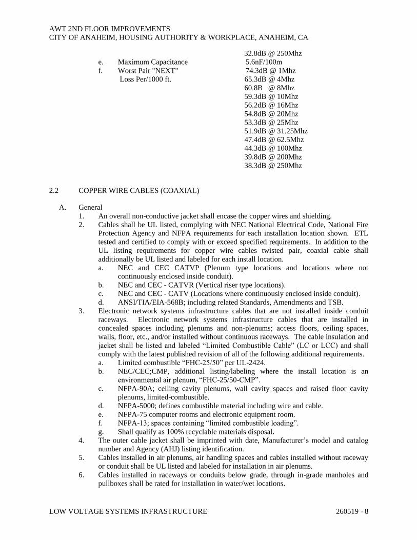
c. Impedance 100 OHM 15%, 1-250Mhz
d. Maximum Signal
Attenuation per 1000 ft. 2.0dB @ 1Mhz
3.8dB @ 4Mhz
5.3dB @ 8Mhz
6.0dB @ 10Mhz
7.6dB @ 16Mhz
8.5dB @ 20Mhz
9.5dB @ 25Mhz
10.7dB @ 31.25Mhz
15.4dB @ 62.5Mhz
19.8dB @ 100Mhz
29.0dB @ 200Mhz
AWT 2ND FLOOR IMPROVEMENTS
CITY OF ANAHEIM, HOUSING AUTHORITY & WORKPLACE, ANAHEIM, CA
LOW VOLTAGE SYSTEMS INFRASTRUCTURE 260519 - 8
32.8dB @ 250Mhz
e. Maximum Capacitance 5.6nF/100m
f. Worst Pair "NEXT" 74.3dB @ 1Mhz
Loss Per/1000 ft. 65.3dB @ 4Mhz
60.8B @ 8Mhz
59.3dB @ 10Mhz
56.2dB @ 16Mhz
54.8dB @ 20Mhz
53.3dB @ 25Mhz
51.9dB @ 31.25Mhz
47.4dB @ 62.5Mhz
44.3dB @ 100Mhz
39.8dB @ 200Mhz
38.3dB @ 250Mhz
2.2 COPPER WIRE CABLES (COAXIAL)
A. General
1. An overall non-conductive jacket shall encase the copper wires and shielding.
2. Cables shall be UL listed, complying with NEC National Electrical Code, National Fire
Protection Agency and NFPA requirements for each installation location shown. ETL
tested and certified to comply with or exceed specified requirements. In addition to the
UL listing requirements for copper wire cables twisted pair, coaxial cable shall
additionally be UL listed and labeled for each install location.
a. NEC and CEC CATVP (Plenum type locations and locations where not
continuously enclosed inside conduit).
b. NEC and CEC - CATVR (Vertical riser type locations).
c. NEC and CEC - CATV (Locations where continuously enclosed inside conduit).
d. ANSI/TIA/EIA-568B; including related Standards, Amendments and TSB.
3. Electronic network systems infrastructure cables that are not installed inside conduit
raceways. Electronic network systems infrastructure cables that are installed in
concealed spaces including plenums and non-plenums; access floors, ceiling spaces,
walls, floor, etc., and/or installed without continuous raceways. The cable insulation and
jacket shall be listed and labeled “Limited Combustible Cable” (LC or LCC) and shall
comply with the latest published revision of all of the following additional requirements.
a. Limited combustible “FHC-25/50” per UL-2424.
b. NEC/CEC;CMP, additional listing/labeling where the install location is an
environmental air plenum, “FHC-25/50-CMP”.
c. NFPA-90A; ceiling cavity plenums, wall cavity spaces and raised floor cavity
plenums, limited-combustible.
d. NFPA-5000; defines combustible material including wire and cable.
e. NFPA-75 computer rooms and electronic equipment room.
f. NFPA-13; spaces containing “limited combustible loading”.
g. Shall qualify as 100% recyclable materials disposal.
4. The outer cable jacket shall be imprinted with date, Manufacturer’s model and catalog
number and Agency (AHJ) listing identification.
5. Cables installed in air plenums, air handling spaces and cables installed without raceway
or conduit shall be UL listed and labeled for installation in air plenums.
6. Cables installed in raceways or conduits below grade, through in-grade manholes and
pullboxes shall be rated for installation in water/wet locations.

AWT 2ND FLOOR IMPROVEMENTS
CITY OF ANAHEIM, HOUSING AUTHORITY & WORKPLACE, ANAHEIM, CA
LOW VOLTAGE SYSTEMS INFRASTRUCTURE 260519 - 9
7. All copper wire electronic network systems cable of the same type shall be produced by
the same Manufacturer, including portable patch cables.
B. RG6 Coaxial Cables
1. ANSI/TIA/EIA-568B cables. RG-6, Quad-Shield cables shall be tested and shall pass
ANSI/TIA/EIA test recommendations for the cable type. Rated for both analog and
digital RF signal circuits.
2. Operational characteristics:
a. Single center conductor size: 18AWG stranded or solid bare copper.
b. Velocity of propagation not less than: 82%.
c. Impedance: 75-OHM 3-OHM.
d. Maximum signal attenuation per 100 feet
▪ Baseband Video 0.26 dB @ 1 MHz
▪ Upstream Digital Cable 0.76 dB @ 10 MHz
▪ TV ch. 2 1.46 dB @ 50 MHz
▪ FM Radio 2.05 dB @ 100 MHz
▪ TV Ch. 12 2.83 db @ 200 MHz
▪ CATV Ch. 54 4.05 dB @ 400 MHz
▪ CATV Ch. 109 5.60 dB @ 700 MHz
▪ CATV Ch. 142 6.23 dB @ 900 MHz
▪ DBS 6.59 db @ 1000 MHz
▪ DBS 7.50 dB @ 1200 MHz
▪ DBS 8.04 dB @ 1450 MHz
▪ PCS Cell Phones 8.50 dB @ 1800 MHz
Wireless Cable 9.00 dB @ 2200 MHz
High Frequency 13.7 dB @ 3000- 4000MHZ
e. Capacitance 16.2 pf/feet
f. ASTM-D4566, 5 thru 4000 MHz
Return Loss Headroom (RLH)
not less than 20 dB
g. 100% sweep tested 5 MHz thru 4500 MHz
3. Four alternating layers of metal foil shielding and brass braiding shielding, 100% metallic
shielding below the jacket and symmetrically enclosing the individual layers of dielectric
insulation surrounding the center conductors.
2.3 COPPER WIRE OUTLET CONNECTORS
A. General
1. Connectors shall comply with FCC part 68 Subpart F for gold plating.
2. Connectors shall be UL listed and shall comply with UL94V-0.
3. Provide a removable blank dust cover for each plug-in outlet insert. The dust cover shall
protect the insert from contamination until a workstation or patch cord is "plugged" into
the outlet.
4. Copper wire outlet connectors shall be color coded to distinguish telephone/ voice
separately (white) from computer/data (blue). The outlet coverplate shall be labeled to
identify telephone/voice, computer/data and other infrastructure outlets separately.
5. Copper wire outlet connectors shall be UL listed, complying with National Electrical
Code, ETL tested and certified to comply with or exceed specified requirements, ANSI/
TIA/EIA-568D including related Standards, Amendments and TSB.
6. All copper wire connectors shall be the product of the same Manufacturer.
AWT 2ND FLOOR IMPROVEMENTS
CITY OF ANAHEIM, HOUSING AUTHORITY & WORKPLACE, ANAHEIM, CA
LOW VOLTAGE SYSTEMS INFRASTRUCTURE 260519 - 10
B. Universal Outlet Connector (for twisted pair Copper Wire Premise/Workstation Wiring and
copper wire patch panels).
1. General
a. Connections for twisted pairs copper conductors shall provide a universal outlet
connector between the building premise copper wire, and plug-in workstation
locations. Patch panel/equipment plug-in connectors. The connector components
shall assemble with "snap-in" spring loaded retainers to prevent dislocation during
insertion or removal of external plug-in devices.
b. The contacts shall be gold plated with a 250 insertion/withdrawal cycle rating.
c. Shall all be the product of the same Manufacturer.
d. Unless specifically noted otherwise the universal outlet connector shall comply
with ANSI/TIA/EIA 568D; related Standards, Amendments and TSB.
e. Operational characteristics shall match or exceed and shall be compatible with the
respective twisted pairs cable.
f. A metal ground shield with EMI/RFI metal ground clip shall be provided where
shielded cable is connected to the universal outlet connector for each universal
outlet connector assembly.
g. Each universal outlet connector shall consist of three major components.
1) Universal edge connector assembly.
2) Plug-in adapter inserts.
3) Connector housing.
h. Provide snap-in blank removable insert covers for connector installed without
plug-in adapter inserts.
2. Universal edge connector:
a. Insulated assembly shall connect to the premise copper wire. The connectors shall
be multiple plug type connector contacts, one contact (total of eight contacts) for
each individual premise wire connection interconnected to the individual wire
terminations.
b. Connector shall provide insertion of individual insulated copper wire, gas tight,
110 style punch down/displacement termination, for 22-26 AWG insulated premise
wire.
c. The edge connector assembly shall provide termination of eight separate wire
conductors, twisted or untwisted pairs, solid or stranded, shielded or unshielded,
with color codes and numbered identification of each contact. Integral cable/
conductor strain relief to prevent pullout of terminated premise wire conductors.
3. Plug-in adapter inserts:
a. Plug-in adapter inserts shall be internally factory connected to the universal edge
connector assembly to adapt the universal connector to the specific outlet type
configuration (i.e. "RJ" style computer/data, telephone/voice, (multimedia)
modular jacks, etc.).
b. Inserts shall be certified for shielded or unshielded wire, to match premise wire
type connected to the universal edge connector.
c. Inserts shall provide correct pin-to-pin connections, electrical and mechanical
matching characteristics for the specific equipment connected to the respective
outlet.
d. Inserts for different infrastructures shall be color coded with different colors from
each other, for system identifications.
e. Plug-in adapter insert type:
1) Computer/data network systems:
a) ANSI/TIA/EIA 568B, female modular jack 8-position/contact "RJ-
45" style, Category-6.
AWT 2ND FLOOR IMPROVEMENTS
CITY OF ANAHEIM, HOUSING AUTHORITY & WORKPLACE, ANAHEIM, CA
LOW VOLTAGE SYSTEMS INFRASTRUCTURE 260519 - 11
2) Telephone/intercom voice systems:
a) ANSI/TIA/EIA 568B female modular jack 8-position/contact RJ-45
style, Category-6.
4. Connector housing:
a. Connector housing shall contain the universal edge connector assembly and the
plug-in adapter inserts in a rigid assembly. Connector housing shall provide
integral cable strain relief for the premise wiring connection.
b. The connector housing shall mount to a 4-port or 6-port white faceplate for hard
wall locations and in surface-mounted boxes attached to the bottom of the kick
plate for work station installations.
C. Coaxial Cable Connectors
1. General
a. F type connectors, for coaxial cable premise/workstation wiring and coaxial cable
patch panel equipment.
b. Unless noted otherwise, the BNC connectors shall comply with ANSI/ TIA/EIA-
568D and related Standards, Addendums and TSB.
c. Brass body and male contact. Beryllium copper or bronze female contact.
Bayonet coupling with threaded or cam-locking mating connection.
d. Shall be the product of the same Manufacturer.
2. Operational characteristics shall match or exceed and shall be compatible with the
respective coaxial cable. 75-OHM, operational frequency range 0-4500 MHz.
2.4 COPPER WIRE PATCH PANELS
A. General
1. Copper wire patch panels shall be UL listed, complying with National Electrical Code,
ETL tested and certified to comply with or exceed specified requirements, ANSI/TIA/
EIA-568D including related Standards, Amendments and TSB.
2. Shall be the product of Belden with 48-ports, suitable for Belden Category 6 cable.
B. Equipment Rack Mounted Patch Panel
1. Standard EIA 19-inches wide metal panel, Manufacturers standard color. Prepunched for
copper wire outlet connectors. Panel shall mount on a EIA standard 19-inches wide
enclosed or open frame equipment rack assembly. Nominal 24 copper wire outlet
connectors in a horizontal row, quantity of rows as required for total quantity of
connectors. Provide not less than two spare empty rows for future copper wire outlet
connectors.
2. The patch panel shall provide the following self-contained functions.
a. Copper wire cable termination including conductor/shield termination and strain
relief.
b. Plug-in copper wire outlet connectors for port to port patching with copper wire
portable patch cords.
3. Patch panel height shall be based on the quantity of copper wire outlet connectors
described plus the specified space for future outlets and shall not exceed the following
dimension height:
Nominal
Outlet Quantity Patch Panel Height
48 7 inches

AWT 2ND FLOOR IMPROVEMENTS
CITY OF ANAHEIM, HOUSING AUTHORITY & WORKPLACE, ANAHEIM, CA
LOW VOLTAGE SYSTEMS INFRASTRUCTURE 260519 - 12
4. Horizontally mounted, cable support metal bracket shall be provided for each 48-outlet/
connector groupings. The brackets shall be bolted to the equipment rack located at the
back side of the patch panel; the brackets shall support and provide strain relief for each
incoming copper wire cable connecting to the patch panel.
5. The copper wire connector installed in the patch panel shall be the same configuration,
Manufacturer and type as the corresponding copper wire connector provided in the
remote workstation outlet locations connecting to the respective patch panel outlet, unless
indicated otherwise.
2.5 EQUIPMENT RACK
A. General
1. A equipment grounding bus, nominal 19 inches long, UL labeled as a ground terminal
bus, shall be provided on each equipment rack. The ground bus shall be bolted to the
rack main metal frame member with 1-inch standoff non-insulating bolts. Provide a
minimum of ten drilled and taped bolt holes in the ground bus with ground lug bolts, for
connection of equipment grounding conductors to the ground bus, size to accept ground
conductors #14-#4 AWG.
2. Vertically mounted, cable management metal rings (aluminum or stainless steel) shall be
provided full height, continuously along the front and rear of each vertical rail of the
equipment rack. The rings shall be bolted to the equipment rack. The rings shall train
and dress portable patch cords connecting between outlet connectors located in the
equipment rack or in adjacent equipment racks.
3. Provide horizontal cable management panels with multiple cable training rings on each
panel (not less than 5 rings for each panel). Management panels (for up to 24 outlet
grouping) nominal 19 inches wide x 1.75 inches high x 3 inches deep and/or (for up to 48
outlet groupings) 3.5 inch high x 3 inches deep, for EIA rack installation. Rings shall
provide horizontal routing and support by grouping portable patch cords connecting
between patch ports in the same equipment rack or adjacent racks. Patch cords shall be
grouped and bundled with “Velcor” tie wraps and shall not overlap patch fields or rack
mounted equipment.
The panels shall be installed on both the front and rear of the equipment racks, mounted
both above and below horizontally between groups of patch ports as follows:
a. One cable management panel (front and rear of rack) for each group of 48 or less
copper wire outlets for patch ports.
b. One cable management panel (front and rear of rack) for each group of 48 fiber
optic outlet patch ports.
4. The entire rack assembly including any support arms shall comply with Seismic Zone 4
earthquake structural standards. The assembly shall provide support for the weight of the
equipment installed on the rack, but in no case less than 500 pounds of equipment, plus
the weight of the rack and connecting cables. A 2.0 times safety factor shall be included
in the equipment rack assembly structural design.
5. Provide Transient Voltage Surge Suppressor with RF Suppresser (TVSS) and Power
Distribution Unit (PDU). 120 volt - 1 phase, 20 ampere 60 Hz AC plug horizontal strip,
mounted in each equipment rack. Each unit shall contain not less than eight “plug-in” on
the rear of the TVSS and not less than two plug-in on the front of the TVSS protected
outlet plugs.
a. Provide two TVSS/PDU units in each equipment rack, to supply “dual-corded”
equipment.
AWT 2ND FLOOR IMPROVEMENTS
CITY OF ANAHEIM, HOUSING AUTHORITY & WORKPLACE, ANAHEIM, CA
LOW VOLTAGE SYSTEMS INFRASTRUCTURE 260519 - 13
6. Provide pre-drilled mounting holes the entire length of equipment vertical mounting
frames, EIA-310D-19 inch (nominal) wide standard spacing for indicated equipment.
Racks shall provide 17.75 inches (nominal) equipment horizontal mounting space
between vertical rails.
7. Provide all floor standing equipment racks with wall bracket support arms extending
from the stationary portion of the rack to adjacent wall. Provide "dual-rail arm" cable
“runway tray”, horizontally from each equipment rack, to the wall directly behind the
equipment rack
a. The tray shall extend from and bolt to the top of the equipment rack “fixed” top
rail.
b. The tray side rail arms shall be a minimum of 6-inches deep, with "ladder" type
rungs spanning horizontally between the side rail arms. The rail arms shall be
parallel with each other. The rail-to-rail arm spacing shall be the same as the
equipment rack width.
c. The rungs shall be spaced not more than 6-inches on center between the side rails,
along the length of the side rail arms. The rungs shall have a minimum cable
bearing surface of not less than 0.75 inches, lengthwise along the tray.
d. The runway tray shall support a minimum of 200 pounds per linear foot live
conductor/cable loading, with not more than 0.25 inches deflection at mid-span.
e. Provide a continuous horizontal support “C” channel along the wall behind the
equipment racks and bolt the dual-rail arm cable runway tray to the channel at the
wall. The channel elevation on the wall above the finish floor shall support the
runway tray horizontally ( 0.2 inches), from the equipment rack to the wall.
f. Equipment racks shall be UL listed, complying with National Electrical Code, ETL
tested and certified to comply with or exceed specified requirements, ANSI/TIA/
EIA-568B including related Standards, Amendments and TSB.
g. The wall mounted horizontal support channel shall be securely through bolt to wall
structural member, a minimum of 16 inches on center. The horizontal support
channel shall extend a minimum of 6-inches past each side of the runway tray. As
manufactured by Unistrut-P1001C Series; or B-Line; or Steel City/Kindorf.
h. Equipment racks shall be Manufacturer’s standard rust inhibitor primer.
Manufacturer’s standard color finish paint over primer, unless noted otherwise.
B. Fixed Position Floor Standing Open Frame Equipment Racks:
1. Floor mounted self-supporting rack, nominal 78-inches of usable mounting frame height
for equipment.
2. Bolted or welded hot dip galvanized steel or gold irradiate finish aluminum support
frame. Hardware shall be stainless steel.
3. Open frame rack construction, fixed, non-swing gate.
a. “Two-post” style for equipment racks not designated as containing UPS equipment
or server equipment.
4. Open frame equipment racks as manufactured by B-Line; or Saunders; or Hendry.
C. Plug Strip Transient Voltage Surge Suppressor (TVSS) and Power Distribution (PDU) Units
1. General
a. Self-contained unit combining plug-in TVSS strip and power distribution unit
PDU. Rated 20 amp, nominal 120 volt +10%, 60Hz, AC, 2400 watts full
continuous load. Internal 20 amp resettable overload protection circuit breaker.
Red illuminated on-off switch. Nine foot, 12 AWG 3-conductor grounded, high
abuse heavy duty jacketed AC, line cord with NEMA 5-20P cap. Multi-outlet
receptacles, suitable for use with the following types of plug in loads; data
AWT 2ND FLOOR IMPROVEMENTS
CITY OF ANAHEIM, HOUSING AUTHORITY & WORKPLACE, ANAHEIM, CA
LOW VOLTAGE SYSTEMS INFRASTRUCTURE 260519 - 14
processing equipment, audio/video equipment, test instruments, medical
equipment, photo graphic equipment and “switching type” power supplies.
b. As manufactured by Libert; or TRIPP LITE.
c. Protected outlet shall be NEMA 5-15R 15 amp, or 20 amp NEMA 5-20R AC 60Hz
receptacles, as applicable for connected equipment loads. Provide not less than
eight protected outlet plugs on each unit. Each individual or group of two
receptacles (duplex) shall be connected to separate protected load isolated filter
banks.
d. Each duplex shall be isolated from the other output receptacles, minimum isolation
of 25Db at 1MHz line to line, line to neutral, line to ground and neutral to ground.
e. Non-blocking plug-in locations/orientation, for plug-in self-contained “power-
brick” power supplies.
2. Operation
Self-contained RFI and EMF shielded housing with mounting slots for temporary
mounting of the unit. Protected outlet receptacles shall supply over current protected and
filtered, electrical line voltage power to the connected equipment. Line noise RFI and
EMI interference filtering suppression, transient voltage surge and spike protection shall
occur in all three modes of operation line to ground, line to neutral and neutral to ground
rated as follows:
a. 13,000 ampere, 210 joules (watt-seconds) peak withstands capacity.
b. Transient response time less than five nano seconds.
c. 140 volt AC RMS initiate spikes suppression 330 volt maximum let through.
d. RFI and EMI Suppression-Provide spectrum analysis test dB attenuation reports
showing RFI filtering over specified frequencies.
e. Diagnostic indicator lights located on the TVSS housing shall provide alarm alert
for each of the following conditions:
1) Loss of AC power.
2) Damage, malfunction in the TVSS suppression circuits.
3) Improper AC electrical outlet wiring.
f. Standards Testing, Listing and Certification Compliance:
1) IEEE 587 A and B compliance.
2) UL 1449 transient voltage surge suppressers.
3) UL 1363 temporary power taps.
4) UL 1283 electromagnetic interference filters.
2.6 WORK STATION OUTLETS
A. General
1. Label (“P-Touch type”) outlet cover plates with the port number corresponding to the
port number at the respective terminal block, patch panel, or head-end equipment.
2. The outlet cover plates shall be factory prepunched and formed to accommodate the
installed outlet connector with attachment screws.
3. Workstation outlets shall be UL listed, complying with National Electrical Code, ETL
tested and certified to comply with or exceed specified requirements, ANSI/TIA/EIA-
568D including related Standards, Amendments and TSB, Category-6.
4. Shall be the product of the same Manufacturer.

AWT 2ND FLOOR IMPROVEMENTS
CITY OF ANAHEIM, HOUSING AUTHORITY & WORKPLACE, ANAHEIM, CA
LOW VOLTAGE SYSTEMS INFRASTRUCTURE 260519 - 15
B. Computer/Data Workstation Copper wire Outlets
1. The outlets shall be the same configuration, same Manufacturer and type as the
corresponding connector provided in the copper wire patch panel outlet, unless noted
otherwise.
2. ANSI/TIA/EIA-568D, and related Standards, Addendums and TSB.
3. The copper wire outlet connectors for twisted pair wire connections in computer
workstation outlets shall be universal outlet connector RJ-45 type.
C. Telephone/Voice Handset Twisted Pair Wire Connection Work Station Outlets
1. The copper wire outlet connectors provided in telephone/voice handset outlets shall be
universal outlet connector type, unless noted otherwise, ANSI/TIA/EIA 568D and related
Standards, Addendums and TSB.
a. RJ-45 type
2. The outlets shall be the product of the same Manufacturer as the computer/data work-
station outlets.
D. Multimedia Audio/Video and TV Workstation Outlets
1. ANSI/TIA/EIA – 568D and related Standards, Addendums and TSB.
a. F type connectors for coaxial cable
b. Shall be the product of the same Manufacturer.
E. Outlet Boxes
1. Wall mounted
a. Flush or surface and size wall mounted outlet box as indicated on the Drawings,
but in no case less than 4.69 inches x 4.69 inches x 2.125 inches deep.
b. Single-gang wide extension ring for outlet box to extend outlet flush with finish
surface, or as noted on the Drawings.
c. Single-gang wide cover plate, or as noted on the Drawings.
2. Inside flush floor boxes and other locations where indicated in the Contract Documents.
F. Multi-outlet Raceway Work Station Outlets
1. Copper wire outlet:
a. Where copper wire connection is indicated for the workstation outlet, provide one
universal outlet connector for each outlet.
b. Each universal outlet connector shall be single connector housing type.
c. Provide a rectangular cutout and metal device plate in the raceway sized to Outlet
Manufacturer's recommendations. The workstation copper wire outlet shall mount
a modular faceplate kit with outlet bezel and faceplate sized to match the
workstation outlet.
d. Offset the location of outlets for electronic network systems 6 inches in the
raceway from other outlets, do not "stack" outlets one above the other in the
raceway.
2.7 PORTABLE PATCH CORDS
A. General
1. Provide portable patch cords for all copper wire infrastructure outlets:
a. For interconnecting electronic network equipment to electronic network
workstation outlets.

AWT 2ND FLOOR IMPROVEMENTS
CITY OF ANAHEIM, HOUSING AUTHORITY & WORKPLACE, ANAHEIM, CA
LOW VOLTAGE SYSTEMS INFRASTRUCTURE 260519 - 16
b. For interconnecting equipment rack patch panel outlet patch locations with each
other.
c. For interconnecting patch panel outlets equipment rack mounted hubs, switches,
routers etc.
2. Patch cords shall be factory assembled tested and certified with factory terminated plugs
at each end. Field terminated portable patch cords shall not be permitted. Terminated
plugs shall incorporate integral bending radius limiting molded “boots” and strain relief.
Patch cord assemblies shall be rated for "heavy duty", “high-abuse” service.
3. Patch cords shall be UL listed, complying with National Electrical Code, ETL tested and
certified to comply with or exceed specified requirements. ANSI/EIA/T1A 568B, related
Standards, Addendums and TSB.
a. NEC and CEC - OFNG/OFN for fiber optic portable patch cords.
b. NEC and CEC - MPP/CMP/CMR/CMG/MPG for copper wire twisted pair
portable patch cords.
c. NEC and CEC - CATV for coaxial cable portable patch cords.
4. Patch cords which are not installed shall be delivered to the OWNER in cardboard boxes.
The patch cords shall be neatly bundled and tied together. Mark each box with quantity
and type of cords contained in the box.
5. Patch cords shall comply with the same cable communication performance requirements
and testing requirements as the respective infrastructure cables and outlets to which the
patch cords are intended to be connected (plug-in) shall be a product of the same
Manufacturer.
6. The outer jacket of each portable patch cord shall be imprinted with date, Manufacturer’s
model and catalog number and AHJ listing identification.
B. Computer/Data Copper Wire Portable Patch Cords
1. Computer/data patch general:
a. "Male" eight positions modular "RJ" male style jacks install on each end of the
patch cord cable. The jack shall be provided with a rear "fin" to prevent the plug
tab from snagging when pulled backwards through adjacent wiring.
b. Patch cord cable shall be UTP to match premise wiring, 4-pair twisted, stranded
copper individually insulated wires, thermoplastic jacket over all the wires and
shield.
c. Connectors shall comply with FCC 68.5 and Part 68 Subpart F.
d. Connectors UL listed and shall comply with UL-94V-O.
e. Contacts gold plated with not less than a 750 insertion/with drawl cycle rating.
2. Patch cord quantities and lengths - for connection from computer workstations to
computer workstation outlets.
a. Patch cord quantity: Provide one complete patch cord assembly for each copper
wire computer workstation outlet located remote from the equipment rack patch
panels. Cable jacket color shall be white.
1) Ethernet network outlet segments the pin-to-pin patch cord wiring
configuration and jacks shall be compatible with the network interface card,
and computer workstation outlet.
b. Provide 10 feet long copper wire patch cables for copper wire computer
workstation outlets. The patch cords shall provide internal cross over wiring to
conform the pin-to-pin connections required between the computer workstation
outlet and the network interface card installed in the respective computer
workstation.

AWT 2ND FLOOR IMPROVEMENTS
CITY OF ANAHEIM, HOUSING AUTHORITY & WORKPLACE, ANAHEIM, CA
LOW VOLTAGE SYSTEMS INFRASTRUCTURE 260519 - 17
3. Patch cord quantities and lengths - for connection from equipment rack patch panel ports
to network HUB and concentrator equipment ports; between network HUB and network
concentrator equipment ports. Cable jacket color shall be white.
a. Patch cord quantity: Provide one complete patch cord assembly for each copper
wire outlet port located in network HUBS and network concentrator equipment.
Provide additional spare patch cords, quantity equal to 15% of the total quantity of
HUB and concentrator ports.
1) Ethernet network outlet segments - the pin-to-pin patch cord wiring
configuration and jacks shall be compatible with the respective network
equipment and patch panel outlets as applicable.
b. Provide the following lengths of copper wire patch cables for outlet ports located
in network HUBS and network concentrators. The patch cords shall provide
quantity of conductors, internal crossover wiring to conform with the pin-to-pin
connectors and jack/connectors to the ports in the HUB's concentrators and
equipment rack patch panels.
1) 2 feet long - 1/3 of total quantity
2) 3 feet long - 1/3 of total quantity
3) 4 feet long - 1/3 of total quantity
C. Coaxial Cable Portable Patch Cords.
1. F type connectors on each end of each patch cord.
2. Patch cord quantity: Provide two complete patch cord assemblies for each coaxial cable
outlet.
a. One patch cord for workstation outlet located remote from the equipment rack
patch panel, 15 feet long each patch cord.
b. One patch cord for equipment rack (IDF/MDF) patch panel each outlet location, 10
feet long each patch cord.
2.8 CIRCUIT PROTECTORS
A. General
1. The circuit protectors shall be UL listed, complying with National Electrical Code, ETL
tested and certified to comply with or exceed specified requirements, ANSI/TIA/EIA-
568D including related Standards, Amendments and TSB.
B. Circuit Protectors
1. Cables containing non-dielectric electrical conducting components entering from the
exterior of the building shall be provided with individual circuit protectors combining
both lightning circuit protection and TVSS circuit protection on each circuit conducting
component, as required in NEC and CEC Articles 770 and 800.
2. Install circuit protectors in the respective backboard/equipment rack where copper wire
conductors terminate, connect each protector to room/closet ground bus equipment with
#10AWG green insulated bond/ground copper conductors.
AWT 2ND FLOOR IMPROVEMENTS
CITY OF ANAHEIM, HOUSING AUTHORITY & WORKPLACE, ANAHEIM, CA
LOW VOLTAGE SYSTEMS INFRASTRUCTURE 260519 - 18
PART 3 - EXECUTION
3.1 EXISTING DATA AND TELEPHONE CABLING
A. All existing data and telephone cabling shall be removed from work station back to
communication room where the new cabling is installed.
3.2 NETWORK CABLE TESTING
A. General
1. In addition to the testing recommended in ANSI/TIA/EIA-568D and related Standards,
Amendments and TSB, test each copper wire conductor, and each connector in all
terminated and unterminated cables, portable patch cord, outlet and patch panel provided
in the Contract shall be tested after installation splicing and termination is completed.
2. Cable Circuit Type of TEST
a. Each patch panel to Attenuation Test and
patch panel segment Signature Trace Test
b. Each patch panel to Attenuation Test
workstation outlet Ring-out Test
c. Transmission link performance ANSI/EIA/TIA-T5B67
d. Electronic network equipment port Transmitter Receiver
to port and port to work station outlet Level Test
e. “NEXT” test Each End of Each Circuit
3. Provide six copies of all test reports, bound in three ring binders to Owner’s
Representative.
4. The Contractor shall repair or replace equipment, cables, outlets, connectors, splices,
terminations, etc. identified during testing as not complying with the Contract
Documents, without additional cost to the Contract. Retest all replaced or repaired
components at Contractor's expenses.
B. The Test Report shall include the following minimum tests:
1. Data of test.
2. Length
3. Propagation delay.
4. Delay skew.
5. Impedance.
6. Attenuation.
7. Tester Manufacturer, model, serial number, hardware and software versions.
8. Insertion loss.
9. Pair-to-Pair Near End Crosstalk (NEXT)
10. Power Sum Near Crosstalk (PSNEXT)
11. Equal Level Far End Crosstalk (ELFEXT).
12. Power Sum Equal Level Far End Crosstalk (PSELFEXT).
13. Return Loss.
14. Shield continuity.
15. The most up-to-date requirements as promulgated.
16. Db loss

AWT 2ND FLOOR IMPROVEMENTS
CITY OF ANAHEIM, HOUSING AUTHORITY & WORKPLACE, ANAHEIM, CA
LOW VOLTAGE SYSTEMS INFRASTRUCTURE 260519 - 19
C. Note that a PASS test is considered 100% passing all testing requirements and a FAIL test is
considered anything less than 100%. City reserves the right to observe any part of the cabling
process, including testing of cabling.
D. Note that the Testing must ultimately pass to the satisfaction of all pending warranty
requirements.
3.3 CABLE INSTALLATION
A. General
1. Cables connecting to equipment racks and terminal blocks shall be installed with not less
than 6-feet of slack cable between the equipment rack/terminal block and terminal
backboard. The slack cable shall be coiled and supported on the backboard and/or cable
tray.
2. Cables in terminal closets and terminal rooms shall be trained, dressed and racked on the
plywood backboards. Provide cable, metal support arms and re-enterable type cable
support rings not less than 12 inches on center mounted onto the plywood along the entire
length of all cables.
3. Provide separate routing paths on plywood backboards for fiber optic cables, computer
data and copper wire cables and telephone/voice copper wire cables and multimedia,
audio/video, TV cables. Provide separate routing paths on plywood backboards for
shielded copper wire cables and unshielded copper wire cables.
4. Cables shall be routed parallel to floors and walls. Do not route cables diagonally on
backboards.
5. Spare cable slack
a. Provide 25 feet of cable slack where unterminated cables are specified at terminal
backboards.
b. Provide a minimum of 18 inches of slack cable in each workstation outlet box and
outlet locations.
c. Provide 10 feet of cable slack in ceiling above each work station outlet.
d. Provide 24 inches of slack in each cable at patch panel locations.
e. Coil and "tye" wrap slack cable.
6. Provide “horizontal wiring” cables installed from individual computer/ data workstation
outlets to respective terminal closet/room patch panel. Cables shall be continuous
without cutting or splices.
7. Provide “horizontal wiring” cables installed from individual workstation telephone/voice
handset outlets to respective terminal closet/room terminal patch panels. Cables shall be
continuous without cutting or splices.
8. Provide “horizontal wiring” cables installed from individual multimedia, audio/ video,
TV outlets to respective terminal closet/room patch panels. Cables shall be continuous
without cutting or splices.
9. Provide cables installed between MDF/IDF terminal rooms/closets patch panels. Cables
shall be continuous without cutting or splices.
B. Cable Pulling Lubrication
1. Cable pulling lubricants shall be specifically approved by the cable Manufacturer. The
following lubricants shall be used where approved by the Cable Manufacturer.
a. Slip X -300, American Colliod Co.
b. Bishop #45, Bishop Electric.
c. MacLube CA51, MacProducts.
AWT 2ND FLOOR IMPROVEMENTS
CITY OF ANAHEIM, HOUSING AUTHORITY & WORKPLACE, ANAHEIM, CA
LOW VOLTAGE SYSTEMS INFRASTRUCTURE 260519 - 20
d. Minerallac H2B,- Minerallac Electric.
e. Winter grade #7437-PC, General Machine Products.
f. Gel-lube 7/5, Cable associates.
g. Polywater, A, C, G - American Polywater.
2. Lubricants shall be continuously applied as cable enters raceway.
C. Cable Installation:
1. Do not pull conductors until factory test reports have been submitted and reviewed.
2. The minimum bending radius for copper wire cables shall be 10 times the cable outside
diameter. The maximum pulling tension and minimum bending radius shall not violate
Manufacturer's recommendations.
3. The attachment of pulling devices directly to the cables shall be with individual split
mesh basket grips. Direct connection for pulling cables to cable fibers and copper wires
shall not occur. Securely tape cable ends to prevent moisture or pulling compound from
penetrating cable.
4. The attachment of the pulling device to the cable basket grips shall be made through a
swivel connector.
5. The Contractor shall ensure that the cables are fed straight into the raceway taking care to
avoid short bends, sharp edges and cable "cross-overs".
6. All lashings used for temporary bunching of the individual cables shall be removed
before the cables enter the raceway.
7. For each cable pull where a cable direction change is required, flexible feed-in tubes,
pullout devices, multi-segmented sheaves etc. shall be used to insure proper cable pulling
tensions and side wall pressures. Cables shall not be pulled directly around a short right
angle bend. Any device or surface the cable comes in contact with when under pull-in
tension shall have a minimum radius 50% greater than the final specified minimum
installed cable bending radius. The maximum possible size radius sheaves and feed-in
tubes, usable in the available working space, shall be provided in all situations, to insure
the minimum possible cable sidewall pulling pressure. Do not use devices with multi-
segment "roller" type sheaves.
8. Cable lengths over 50 feet shall be machine pulled not hand pulled into and through all
raceways. Cables shall be pulled in a continuous, smooth operation without jerking or
stop-start motion after initiation of pull. Maximum cable pulling speed shall be less than
50 feet per minute. Minimum cable pulling speed shall be greater than 15 feet per
minute.
9. Cables shall be pulled straight into or out of the raceway without bends at the raceway
entrance or exit. Pull in cable from the end having the sharpest bend (i.e., bend shall be
closest to reel). Keep pulling tension to minimum by liberal use of lubricant, hand
turning of reel, and slack feeding of cable into duct entrance. Employ not less than one
man at reel and one at manhole or pullhole during this operation. Cables shall be pulled
directly from cable reels.
10. Where cable tray is provided, all cables shall be routed and trained on the cable tray. The
cables shall enter the cable tray and route along the tray prior to entering any equipment
racks or computer works station outlets.
11. A dynamometer to measure pulling tension shall be used on all cable runs in excess 200
feet or with more than 180 degrees in bends. The actual pulling tension value shall be
calculated and recorded for each pull.
12. Bends shall not be made in cable splices or terminations.

AWT 2ND FLOOR IMPROVEMENTS
CITY OF ANAHEIM, HOUSING AUTHORITY & WORKPLACE, ANAHEIM, CA
LOW VOLTAGE SYSTEMS INFRASTRUCTURE 260519 - 21
13. The portions of cables installed without raceways or cable tray supports shall be installed
with metal “J-hook” cable supports.
a. The “J-hooks” shall provide multi-tiered “J” shaped hooks, with wide flat cable
support base (0.5 inch wide minimum) and smooth rounded corners. Specifically
designed for copper wire and fiber optic infrastructure cable support. As
manufactured by Erico Inc.
b. The individual “J-hook” attachment to the building structure shall be metal, “beam
clamp”, “hanger rod”, clevis hanger styles as applicable for each attachment
location.
c. Install “J-hooks” not more than 48 inches on center along the entire cable length
and within 6 inches of each cable change in direction. Locations of “J-Hooks” and
tension of cables shall insure between 4-inches and 6 inches of cable sag between
adjacent hooks. Secure cables to “J-hooks” with re-enterable cable tie wraps. “J-
hook” supported cables, bundle cables together with re-enterable tie wraps not less
than 12 inches on center along the entire cable length.
d. Each J-hook shall not support more than 12 individual cables. Provide multiple
“tiered” J-hooks for additional cable quantities at each location.
e. “Bridle rings” shall NOT be used to support cables.
f. Cables shall not lie directly on nor attach to ceilings, ceiling hangers, lighting
fixtures, air ducts, piping, or equipment.
14. Re-enterable cable tie wraps shall be, “limited-combustible” and air plenum rated,
reusable, color coded. Chemically and mechanically compatible with the respective
cables and install locations. Shall allow multiple open-close operations for securing
cables.
15. Electronic network cables containing non-dielectric components shall be installed with a
minimum separation from other electrical power conductors and equipment as follows:
Equipment Type Minimum Separation
a. Lighting fixtures 12 inches
b. Electric motors, electric solenoids, electric Heaters 40 inches
c. Transformers 48 inches
d. Circuits over 100 volts to ground, in metallic raceways 5 inches
e. Circuits over 100 volts to ground, in non-metallic
raceway or without any raceway 12 inches
f. Circuits over 100 volts to ground, suspended on
overhead pole lines 48 inches
D. Movement, Storage, and Handling of Cable:
1. Reels of cable shall not be dropped from any height, from trucks or other transporting
equipment.
2. Lift and move cable reels using following methods:
a. Crane or boom type equipment-insert shaft (heavy rod or pipe) through reel hubs
and lift with slings on shaft, with spreader or yoke to reduce or avoid sling pressure
against reel head.
b. Fork lift type of equipment may be used to move smaller, narrower width reels.
Fork times should be placed so that lift pressure is on reel heads, not on cable, and
shall reach all the way across reels so lift is against both reel heads.
c. Reels may be moved short distances by rolling. Reels shall be rolled in the
direction indicated by arrows painted on reel heads. Surfaces over which the reels
are to be rolled shall be solid clear of debris, and also clear of protruding stones,
humps, etc. which might damage the cable if the reel straddles them.

AWT 2ND FLOOR IMPROVEMENTS
CITY OF ANAHEIM, HOUSING AUTHORITY & WORKPLACE, ANAHEIM, CA
LOW VOLTAGE SYSTEMS INFRASTRUCTURE 260519 - 22
3. Storage of reels of cable:
a. Cable ends shall be sealed prior to shipment to prevent moisture entry into cable.
Cable ends shall remain sealed at all times including during installation. Where
ends seals are removed, reseal cable ends by stripping cable finishes back 2-inches
down to insulation. Then apply four layers of an insulating tape criss-cross over
the cable end and carry back at least 4-inches onto cable outer finish. Add a
containing cover of two layers of vinyl electrical tape completely over the end seal.
b. Cable reels shall be shipped with factory applied lagging (protective cover) left in
place until removal is absolutely necessary. Additional covering such as tarpaulin,
plastic sheeting, etc. shall be used if cable is to be stored outdoors.
c. Store reels of cable on a firm surface, paved, or on planking to prevent settling into
soft ground.
d. Use fencing or other barriers to protect cables and reels against damage by vehicles
or other equipment moving about in the storage area.
3.4 CABLE SPLICES
A. General
1. Splices only where absolutely necessary and upon written approval from City. Splice(s)
in cables shall occur only in the following locations:
a. Terminal backboard, closets or rooms.
b. Equipment racks.
c. Wall mounted interface cabinet.
d. Do not splice cables in conduit, cable tray, raceways or plenums.
2. Polarity and color coding shall be maintained consistent through splices, terminations and
outlets for the entire electronic network system.
3. Cable splices in outdoor areas, manholes, pullholes shall be water tight, inside universal
splice enclosures.
B. Copper Wire Splice
1. Copper wire extending from infrastructure workstation outlets to respective equipment
rack patch panel outlets shall not be cut or broken and shall be continuous end to end.
2. Copper wire extending from telephone/voice workstation outlets to respective terminal
blocks shall not be cut or broken and shall be continuous end to end.
3. Continuity of cable shields (where occurs), polarity and color coding shall be maintained
across all splices.
4. Copper wire splices shall be performed to maintain the data transmission rates specified
for the entire respective system.
3.5 CABLE TERMINATIONS
A. General
1. Infrastructure workstation outlets connecting to ports in patch panels and terminal blocks
shall be grouped together in the patch panel and terminal block] by outlet function, room
location and building area location (i.e. Group #1 Room #120 1st floor; Group #2 Room
200 east wing, etc.). Each group shall be identified with engraved (etched) nameplates
indicating grouping identification and individual port numbers.
2. Polarity and color coding of cable connections at splices, terminations and outlets shall be
consistently maintained throughout the entire electronic network system.
AWT 2ND FLOOR IMPROVEMENTS
CITY OF ANAHEIM, HOUSING AUTHORITY & WORKPLACE, ANAHEIM, CA
LOW VOLTAGE SYSTEMS INFRASTRUCTURE 260519 - 23
3. Terminate all cables onto respective outlets connectors, interconnection couplers and
terminals. Terminations shall comply with Manufacturer's recommendations; ANSI/TIA/
EIA-568D related Standards, Amendments and TSB.
4. Copper wire cable conductors terminated at outlet locations shall be connected with a
strain relief device attached to the cable jacket to prevent cable tension from being
transmitted to the termination connectors.
B. Copper Wire Terminations
1. Where occurs, the shield on metal shielded copper wire shall be terminated and
connected to the shield grounding connection at each termination point.
2. Twisted wire pairs shall not be untwisted for a length of more than 0.4 inches at any
location and the cable jacket shall not be striped back not more than 0.5 inches any
location including splices and terminations.
3. Unless specifically directed otherwise by the Owner's Representative, Pin assignment for
wiring terminations shall comply with ANSI/TIA/EIA 568D as required for compatibility
with the electronic network equipment. The termination type shall be consistent
throughout the Project Contract area.
4. Copper wire termination's shall be performed to maintain the transmission rates specified
for the respective entire system.
3.6 EQUIPMENT RACKS
A. General
1. Install, assemble, mount and connect devices and equipment in the respective equipment
racks, bolted securely to the rack frame with stainless steel hardware. "Star" style lock
washers shall be provided to insure an electrically continuous ground path between the
equipment/devices and rack frames.
2. Provide blank metal filler panels to close unused equipment "front" mounting space in
equipment racks, Manufacturer's standard finish color.
3. Provide a copper wire outlet connector in the respective equipment rack for each remote
copper wire infrastructure workstation outlet and copper wire cable shown connected to
the respective equipment rack, plus the spare copper wire outlet connectors required in
the Contract Documents. The copper wire outlet connectors in the equipment racks shall
be provided in equipment rack mounted copper wire patch panels. In no case shall the
quantity of equipment rack mounted copper wire outlet connectors be less than the
quantity of cables indicated on the Drawings, plus required spaces/ spares.
4. The maximum quantity of cable terminations, in each equipment rack mounted patch
panels shall not exceed the following:
a. 100% copper wire outlet connectors, 196 maximum per rack.
b. Combination of copper wire outlet connectors and fiber optic fiber terminations in
the same rack; 48 maximum fiber optic fibers plus 144 maximum copper wire
outlet connectors per rack.
c. In addition to the quantity of patch panel outlets for termination of incoming and
outgoing cables, provide not less than an additional 15% of patch panel spare
outlets in each equipment rack for future use.
Provide additional equipment racks, quantity of racks to ensure the maximum
specified quantity of terminations in single rack are not exceeded and the quantity
of cable terminations complies with the requirements of the Contract Documents.
AWT 2ND FLOOR IMPROVEMENTS
CITY OF ANAHEIM, HOUSING AUTHORITY & WORKPLACE, ANAHEIM, CA
LOW VOLTAGE SYSTEMS INFRASTRUCTURE 260519 - 24
5. Terminal racks, equipment locations, patch panels, and cross connects shall be arranged
to allow for natural cabling progression, minimize crossing of cables and allow easy
access to each system component.
6. Equipment Rack Anchorage:
a. Equipment racks installed on raised "access floor" systems, shall be supported and
anchored with bolts that extend into the "structural" floor located below the "access
floor".
b. Securely anchor the support arms of swing gate racks to the wall structural support
system.
c. Securely anchor fixed support base of the racks to the floor.
d. Mounting method shall support the total rack weight including installed
equipment, but in no case less than 500 pounds with a 2.0 times safety factor.
e. Attachments and anchorages shall comply with the requirements for Earthquake
Seismic Zone 4.
7. Install ground bus, TVSS, cable management rings, equipment, patch panel and patch
panel outlets, etc. in equipment racks.
B. Floor Standing Equipment Racks
1. General:
a. Securely anchor racks to floor.
b. All incoming cables shall enter through the top or bottom of the racks.
c. The front of the racks shall maintain a minimum of 42-inches of clear working
space.
d. Multiple floor standing racks shall be installed directly adjacent to each other (i.e.
side by side), with not less than 6-inches (edge-to-edge) space between adjacent
racks.
2. Floor standing open (non-swing gate) equipment racks.
a. The rear of the rack shall maintain a minimum of 54-inches clear working space
behind the rack frame rails for adequate installation depth of HUBS/switches
equipment, for "walk" behind access to equipment and for cable terminations
access.
b. Provide a minimum spacing between (edge-to-edge) racks of not less than 6-
inches.
3.7 TERMINAL ROOMS AND CLOSETS
A. Terminal Backboard
1. A ¾-inch thick marine "A-C" grade plywood backboard shall fully cover each wall of
terminal closets and terminal rooms. Provide backboard on the wall for equipment racks,
incoming cable raceways and terminal blocks. Plywood shall extend from the finish floor
to 8 feet above the finish floor. "A" side of plywood shall be exposed.
2. Attach plywood to wall structural framing with mechanical fasteners a minimum 6 inches
on center vertically on walls at each framing vertical member, and along the length of the
wall, but not less than 16 inches on center horizontally along the length of the wall.
3. Paint plywood terminal backboards after installation and prior to mounting any
equipment. One coat of wood paint fire resistant primer and two coats of Class-A fire
resistant/intumescent, non-conductive finish coats of paint. Finish flat/matt acrylic
enamel fire resistant/retardant latex paint.

AWT 2ND FLOOR IMPROVEMENTS
CITY OF ANAHEIM, HOUSING AUTHORITY & WORKPLACE, ANAHEIM, CA
LOW VOLTAGE SYSTEMS INFRASTRUCTURE 260519 - 25
B. Cable Tray
1. Where one or more equipment racks are installed in the same room/closet.
a. Provide a horizontal cable tray above the equipment racks in each circuit terminal
room and closet.
b. Provide a horizontal cable tray continuous “loop” around the perimeter inside each
MDF and IDF room, within 12-inches of the ceiling. Parallel with and adjacent to
all walls in the room.
2. Ladder type cable tray 18 inches wide x 6 inches deep; length-end wall to end wall, of the
closet or room.
3. Install the cable tray centered above all equipment racks and around the room perimeter
at ceiling/walls with ceiling and wall suspension system. Install trays not more than 36
inches above and not less than 12 inches above the top of the equipment racks.
4. Where multiple segments of cable trays occur in terminal closets and rooms, provide
interconnecting cable trays between each segment located in the respective room/closet.
C. Conductor Training and Support
1. Provide conductor/cable training and racking support distribution rings installed on
backboards. As manufactured by Newton 3042 Series, Saunders or equal.
2. Support rings shall be spaced a minimum of 10 inches on center along all cable/conductor
routing paths on backboards and within 4 inches of each change in cable/conductor
direction.
3. The capacity of support rings shall be equal to the weight and quantity of conductors/
cables passing through the respective support ring plus 100% spare capacity for
installation future conductors/cables. In no case shall support rings be smaller than 3
inches.
4. Attach support rings to backboards with not less than two 3/8-inch diameter x 1⅛-inch
long threaded wood anchor bolts for each individual bracket.
D. Environment Space Monitoring (MDF and IDF)
1. In each room/closet provide one automatic environmental monitor. Self-calibrating,
simultaneous monitoring and software programmable, with alarm set points, shall
measure and monitor ambient conditions and provide data-logging for conditions in the
space for the following:
a. One ambient temperature port and plug-in indoor sensor.
b. One ambient humidity port and plug-in indoor sensor.
c. One spare plug-in port for an external digital sensor.
2. Digital Fast Ethernet LAN RJ-45 communications port, with alarm alerting and
communications software for remote monitoring of the ambient conditions via the LAN.
Multi-user site wide software license, compatible with PC-computer and IP-WEB HTTP
remote operations.
3. Local internal audio and visual alert annunciators, with local silence and reset.
4. 120 volt, 60Hz AC input power supply operation. Equipment rack mount self-contained
unit housing configuration. Provide all interconnect cabling and connectors.
5. Provide the environmental unit in one of the equipment racks located in each of the
respective spaces.
6. As manufactured by Avtech-Room Alert; or SensaTronic-Environmental Systems; or IT
Watch Dog-Climate Monitors.
AWT 2ND FLOOR IMPROVEMENTS
CITY OF ANAHEIM, HOUSING AUTHORITY & WORKPLACE, ANAHEIM, CA
LOW VOLTAGE SYSTEMS INFRASTRUCTURE 260519 - 26
3.8 IDENTIFICATION (ADDITIONAL REQUIREMENTS)
A. General
1. Copper wire cables shall be identified in each manhole, pull box, equipment rack, patch
panel and computer workstation outlets.
2. Infrastructure documentation, identification labels and color coding shall comply with
ANSI/TIA/EIA-606A Administration Standard for Telecommunications Infrastructures,
Class-1 thru Class-4. Provide management software MS-Windows-based single user
license, with all as-built data entry documentation information complete.
B. Identification Tags shall include the following information:
1. Cable name as indicated on Drawings (i.e., HV1, F4, MSB3 etc.).
2. Installation month and date (i.e., 3/92, 4/78 etc.).
3. Conductor size conductor type (i.e., loose tube fiber; (#24 AWG ScTP Category 5, 200-
pair, telephone/voice etc.).
4. Feeder taps to equipment or building shall also be identified with equipment name or
building (i.e. library, SW1, Rack #21, etc.)
C. Identification Tags
1. Tags shall be ⅛-inch thick 98% lead, approximately 2-inches square with chamfered
corners. Two holes shall be drilled for attachment to primary cable. Lettering shall be
⅛-inch high, engraved or die stamped. Attach tags to primary cables with two #14 AWG
(THWN insulated) solid copper conductors "twist-tied", with insulated CAP wire-nut on
the tie-wire ends, to cover sharp edges of tie-wire conductor.
2. Alternate identification tags, at the Contractor's option in lieu of lead tags. Provide
polypropylene tag holders with interchangeable, yellow polypropylene tag with black
alphanumeric characters sets. Characters shall be approximately .25-inch high. As
manufactured by Almetek industries "EZTAG" - Ledgewood, New Jersey.
D. Equipment and Outlet Naming Identification and Color Coding shall comply with ANSI/EIA/
TIA latest revision.
END OF SECTION 260519
102317/176103