axi4-stream infrastructure ip suite v3 · axi4-stream infrastructure ip suite v3.0 5 pg085 december...
TRANSCRIPT

AXI4-Stream Infrastructure IP Suite v3.0LogiCORE IP Product Guide
Vivado Design Suite
PG085 December 5, 2018
AXI4-Stream Infrastructure IP Suite v3.0 2PG085 December 5, 2018 www.xilinx.com
Table of Contents
IP Facts
Chapter 1: Overview
Overview of Features. . . . . . . . . . . . . . . . . . . . . . . . . . . . . . . . . . . . . . . . . . . . . . . . . . . . . . . . . . . . . . . 7
System Requirements . . . . . . . . . . . . . . . . . . . . . . . . . . . . . . . . . . . . . . . . . . . . . . . . . . . . . . . . . . . . . . 9
Licensing and Ordering . . . . . . . . . . . . . . . . . . . . . . . . . . . . . . . . . . . . . . . . . . . . . . . . . . . . . . . . . . . . . 9
Chapter 2: Product Specification
AXI4-Stream Infrastructure IP Suite Modules . . . . . . . . . . . . . . . . . . . . . . . . . . . . . . . . . . . . . . . . . . 10
Standards . . . . . . . . . . . . . . . . . . . . . . . . . . . . . . . . . . . . . . . . . . . . . . . . . . . . . . . . . . . . . . . . . . . . . . . 17
Performance. . . . . . . . . . . . . . . . . . . . . . . . . . . . . . . . . . . . . . . . . . . . . . . . . . . . . . . . . . . . . . . . . . . . . 17
Resource Utilization. . . . . . . . . . . . . . . . . . . . . . . . . . . . . . . . . . . . . . . . . . . . . . . . . . . . . . . . . . . . . . . 19
Port Descriptions . . . . . . . . . . . . . . . . . . . . . . . . . . . . . . . . . . . . . . . . . . . . . . . . . . . . . . . . . . . . . . . . . 21
Register Space . . . . . . . . . . . . . . . . . . . . . . . . . . . . . . . . . . . . . . . . . . . . . . . . . . . . . . . . . . . . . . . . . . . 26
Chapter 3: Designing with the Core
General Design Guidelines . . . . . . . . . . . . . . . . . . . . . . . . . . . . . . . . . . . . . . . . . . . . . . . . . . . . . . . . . 29
Clocking. . . . . . . . . . . . . . . . . . . . . . . . . . . . . . . . . . . . . . . . . . . . . . . . . . . . . . . . . . . . . . . . . . . . . . . . . 30
Resets . . . . . . . . . . . . . . . . . . . . . . . . . . . . . . . . . . . . . . . . . . . . . . . . . . . . . . . . . . . . . . . . . . . . . . . . . . 31
Chapter 4: Design Flow Steps
Customizing and Generating the Core . . . . . . . . . . . . . . . . . . . . . . . . . . . . . . . . . . . . . . . . . . . . . . . . 32
Constraining the Core . . . . . . . . . . . . . . . . . . . . . . . . . . . . . . . . . . . . . . . . . . . . . . . . . . . . . . . . . . . . . 68
Simulation . . . . . . . . . . . . . . . . . . . . . . . . . . . . . . . . . . . . . . . . . . . . . . . . . . . . . . . . . . . . . . . . . . . . . . 70
Synthesis and Implementation . . . . . . . . . . . . . . . . . . . . . . . . . . . . . . . . . . . . . . . . . . . . . . . . . . . . . . 70
Chapter 5: Example Design
Functionality. . . . . . . . . . . . . . . . . . . . . . . . . . . . . . . . . . . . . . . . . . . . . . . . . . . . . . . . . . . . . . . . . . . . . 72
Chapter 6: Test Bench
Appendix A: Upgrading
Device Migration . . . . . . . . . . . . . . . . . . . . . . . . . . . . . . . . . . . . . . . . . . . . . . . . . . . . . . . . . . . . . . . . . 74
Send Feedback

AXI4-Stream Infrastructure IP Suite v3.0 3PG085 December 5, 2018 www.xilinx.com
Migrating to the Vivado Design Suite. . . . . . . . . . . . . . . . . . . . . . . . . . . . . . . . . . . . . . . . . . . . . . . . . 74
Upgrading in the Vivado Design Suite . . . . . . . . . . . . . . . . . . . . . . . . . . . . . . . . . . . . . . . . . . . . . . . . 74
Appendix B: Debugging
Finding Help on Xilinx.com . . . . . . . . . . . . . . . . . . . . . . . . . . . . . . . . . . . . . . . . . . . . . . . . . . . . . . . . . 76
Debug Tools . . . . . . . . . . . . . . . . . . . . . . . . . . . . . . . . . . . . . . . . . . . . . . . . . . . . . . . . . . . . . . . . . . . . . 77
Hardware Debug . . . . . . . . . . . . . . . . . . . . . . . . . . . . . . . . . . . . . . . . . . . . . . . . . . . . . . . . . . . . . . . . . 78
Interface Debug . . . . . . . . . . . . . . . . . . . . . . . . . . . . . . . . . . . . . . . . . . . . . . . . . . . . . . . . . . . . . . . . . . 78
Appendix C: Additional Resources and Legal Notices
Xilinx Resources . . . . . . . . . . . . . . . . . . . . . . . . . . . . . . . . . . . . . . . . . . . . . . . . . . . . . . . . . . . . . . . . . . 80
Documentation Navigator and Design Hubs . . . . . . . . . . . . . . . . . . . . . . . . . . . . . . . . . . . . . . . . . . . 80
References . . . . . . . . . . . . . . . . . . . . . . . . . . . . . . . . . . . . . . . . . . . . . . . . . . . . . . . . . . . . . . . . . . . . . . 81
Revision History . . . . . . . . . . . . . . . . . . . . . . . . . . . . . . . . . . . . . . . . . . . . . . . . . . . . . . . . . . . . . . . . . . 81
Please Read: Important Legal Notices . . . . . . . . . . . . . . . . . . . . . . . . . . . . . . . . . . . . . . . . . . . . . . . . 82
Send Feedback
AXI4-Stream Infrastructure IP Suite v3.0 4PG085 December 5, 2018 www.xilinx.com Product Specification
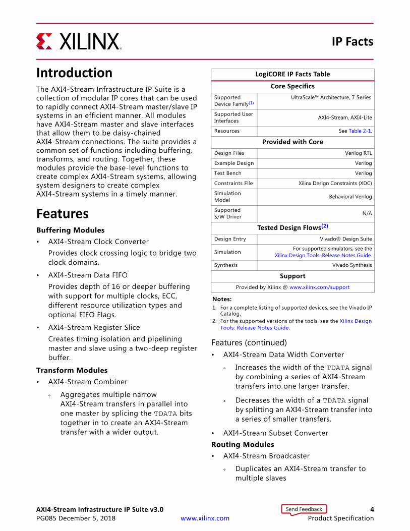
IntroductionThe AXI4-Stream Infrastructure IP Suite is a collection of modular IP cores that can be used to rapidly connect AXI4-Stream master/slave IP systems in an efficient manner. All modules have AXI4-Stream master and slave interfaces that allow them to be daisy-chained AXI4-Stream connections. The suite provides a common set of functions including buffering, transforms, and routing. Together, these modules provide the base-level functions to create complex AXI4-Stream systems, allowing system designers to create complex AXI4-Stream systems in a timely manner.
FeaturesBuffering Modules• AXI4-Stream Clock Converter
Provides clock crossing logic to bridge two clock domains.
• AXI4-Stream Data FIFOProvides depth of 16 or deeper buffering with support for multiple clocks, ECC, different resource utilization types and optional FIFO Flags.
• AXI4-Stream Register SliceCreates timing isolation and pipelining master and slave using a two-deep register buffer.
Transform Modules• AXI4-Stream Combiner
° Aggregates multiple narrow AXI4-Stream transfers in parallel into one master by splicing the TDATA bits together in to create an AXI4-Stream transfer with a wider output.
Features (continued)• AXI4-Stream Data Width Converter
° Increases the width of the TDATA signal by combining a series of AXI4-Stream transfers into one larger transfer.
° Decreases the width of a TDATA signal by splitting an AXI4-Stream transfer into a series of smaller transfers.
• AXI4-Stream Subset ConverterRouting Modules• AXI4-Stream Broadcaster
° Duplicates an AXI4-Stream transfer to multiple slaves
IP Facts
LogiCORE IP Facts Table
Core Specifics
Supported Device Family(1)
UltraScale™ Architecture, 7 Series
Supported User Interfaces AXI4-Stream, AXI4-Lite
Resources See Table 2-1.
Provided with Core
Design Files Verilog RTL
Example Design Verilog
Test Bench Verilog
Constraints File Xilinx Design Constraints (XDC)
Simulation Model Behavioral Verilog
Supported S/W Driver N/A
Tested Design Flows(2)
Design Entry Vivado® Design Suite
Simulation For supported simulators, see theXilinx Design Tools: Release Notes Guide.
Synthesis Vivado Synthesis
Support
Provided by Xilinx @ www.xilinx.com/support
Notes: 1. For a complete listing of supported devices, see the Vivado IP
Catalog.2. For the supported versions of the tools, see the Xilinx Design
Tools: Release Notes Guide.
Send Feedback
AXI4-Stream Infrastructure IP Suite v3.0 5PG085 December 5, 2018 www.xilinx.com Product Specification
IP Facts
• AXI4-Stream Switch
° Allows multiple masters and slave to be connected by using the TDEST signal to route transfers to different slaves.
° Optional control register routing mode that uses an AXI4-Lite interface to specify routing.
• AXI4-Stream Interconnect (Requires Vivado).
° Allows masters and slaves with differing AXI4-Stream characteristics to exchange AXI4-Stream transfers.
Send Feedback
AXI4-Stream Infrastructure IP Suite v3.0 6PG085 December 5, 2018 www.xilinx.com
Chapter 1
OverviewThe Arm® AMBA® 4 Specification builds on the AMBA 3 specifications by adding new interface protocols to provide greater interface flexibility in designs with open standards. Among the new interface protocols is the AXI4-Stream interface which is designed to support low resource, high bandwidth unidirectional data transfers. It is well-suited for FPGA implementation because the transfer protocol allows for high frequency versus clock latency trade-offs to help meet design goals.
The AXI4-Stream protocol is derived from the single AXI3 write channel. It has no corresponding address or response channel and is capable of non-deterministic burst transactions (undefined length). The protocol interface signal set adds optional signals to support data routing, end-of-transaction indicators, and null-beat modifiers to facilitate management and movement of data across a system. These characteristics are suitable for transferring large amounts of data efficiently while keeping gate count low.
The protocol interface consists of a master interface and a slave interface. The two interfaces are symmetric and point-to-point, such that master interface output signals can connect directly to the slave interface input signals. Utilizing this concept, it is possible to design AXI4-Stream modules that have a slave interface input channel and a master interface output channel. Because the master and slave interfaces are symmetric, any number of these modules can be daisy-chained together by connecting the master interface output channel of one module to the slave interface input channel of another module and so on. The function of the modules can be a multitude of different options such as buffering, data transforming or routing.
The AXI4-Stream Infrastructure IP Suite is a powerful collection of modules that provides a rich set of functions for connecting together AXI4-Stream masters and slaves. The IP core is capable of performing data switching/routing, data width conversion, pipelining, clock conversion and data buffering. Parameters and IP configuration Graphical User Interfaces (GUIs) are used to configure the core to suit each of the system designer's requirements.
Send Feedback
AXI4-Stream Infrastructure IP Suite v3.0 7PG085 December 5, 2018 www.xilinx.com
Chapter 1: Overview
Overview of FeaturesThe AXI4-Stream Infrastructure IP Suite consists of eight modular IP cores supporting the full AXI4-Stream specification. Common features include:
• AXI4-Stream compliant
° Supports all AXI4-Stream defined signals: TVALID, TREADY, TDATA, TSTRB, TKEEP, TLAST, TID, TDEST, and TUSER.
° TDATA, TSTRB, TKEEP, TLAST, TID, TDEST, and TUSER are optional.
° Programmable TDATA, TID, TDEST, and TUSER widths (TSTRB and TKEEP width is TDATA width/8).
° ACLK/ARESETn ports.
° Per port ACLKEN inputs (optional).
AXI4-Stream Broadcaster• Replicates a master stream into multiple output slave streams.
• Provides TDATA/TUSER remap functionality.
• Supports 2-16 slaves.
AXI4-Stream Clock Converter• Supports low latency and area synchronous 1:N and N:1 clock conversion.
• Supports asynchronous clock conversion.
• Supports configurable ACLKEN conversion.
AXI4-Stream Combiner• Combines multiple "narrow" streams into one wide output stream.
• Supports 2-16 masters.
• Supports error detection for unmatched TLAST, TID, or TDEST signals slave interfaces.
AXI4-Stream Data FIFO• Supports FIFO depths from 16-32,678 in powers of 2.
• Supports Distributed RAM, Block RAM, and UltraRAM (on select devices) memory primitive types.
• Utilizes Xilinx Parameterized Macros for automatic constraint generation and FIFO implementation.
• Supports independent read/write clocks and ACLKEN conversion.
Send Feedback
AXI4-Stream Infrastructure IP Suite v3.0 8PG085 December 5, 2018 www.xilinx.com
Chapter 1: Overview
• Supports Packet Mode (Store and Forward based on TLAST).
• Supports error correction code (ECC) with optional ECC error injection inputs.
• Optional FIFO Flags: write data count, almost full, programmable full, read data count, almost empty, and programmable empty.
AXI4-Stream Data Width Converter• Supports 1:N TDATA width size increase in a single stage.
• Supports N:1 TDATA width size decrease in a single stage.
• Supports arbitrary M:N TDATA width conversion in multiple stages.
AXI4-Stream Register Slice• Allows pipelining of AXI4-Streams.
• Provides timing isolation.
• Optional pipelining to cross super logic regions (SLRs) in stacked silicon interconnect (SSI) devices.
AXI4-Stream Subset Converter• Provides TDATA/TUSER remap functionality.
• Allows streams with different signal sets to be connected.
• Can generate a programmable TLAST.
• Can tie-off unused signals from masters.
• Can add signals based on default value rules.
AXI4-Stream Switch• Supports 1-16 slaves.
• Supports 1-16 masters.
• Has slave side arbitrated crossbar switch.
• Supports multiple arbitration tuning points:
° Ability to arbitrate based on TLAST.
° Ability to arbitrate based on number of transfers.
° Ability to arbitrate based on a timeout (counts number of consecutive LOW TVALID cycles).
• Supports Round-Robin, True Round-Robin, and Fixed Priority arbitration choices.
• Supports sparse connectivity.
Send Feedback

AXI4-Stream Infrastructure IP Suite v3.0 9PG085 December 5, 2018 www.xilinx.com
Chapter 1: Overview
• Supports routing based on TDEST base/high pairs OR optional control register routing with AXI4-Lite interface.
AXI4-Stream InterconnectNote: AXI4-Stream Interconnect requires Vivado IP integrator.
• Supports 1-16 slaves
• Combines AXI4-Stream Switch with buffering modules, AXI4-Stream Data Width Converter and AXI4-Stream Subset Converter to allow masters and slaves with varying AXI4-Stream characteristics to exchange AXI4-Stream transfers.
System RequirementsFor a list of System Requirements, see the Xilinx Design Tools: Release Notes Guide.
Licensing and OrderingThis Xilinx LogiCORE™ IP module is provided at no additional cost with the Xilinx Vivado® Design Suite under the terms of the Xilinx End User License. Information about other Xilinx LogiCORE IP modules is available at the Xilinx Intellectual Property page. For information about pricing and availability of other Xilinx LogiCORE IP modules and tools, contact your local Xilinx sales representative.
Send Feedback
AXI4-Stream Infrastructure IP Suite v3.0 10PG085 December 5, 2018 www.xilinx.com
Chapter 2
Product Specification
AXI4-Stream Infrastructure IP Suite Modules
AXI4-Stream Broadcaster
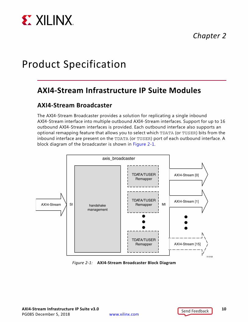
The AXI4-Stream Broadcaster provides a solution for replicating a single inbound AXI4-Stream interface into multiple outbound AXI4-Stream interfaces. Support for up to 16 outbound AXI4-Stream interfaces is provided. Each outbound interface also supports an optional remapping feature that allows you to select which TDATA (or TUSER) bits from the inbound interface are present on the TDATA (or TUSER) port of each outbound interface. A block diagram of the broadcaster is shown in Figure 2-1.
X-Ref Target - Figure 2-1
X-Ref Target - Figure 2-2
Figure 2‐1: AXI4-Stream Broadcaster Block Diagram
Send Feedback
AXI4-Stream Infrastructure IP Suite v3.0 11PG085 December 5, 2018 www.xilinx.com
Chapter 2: Product Specification
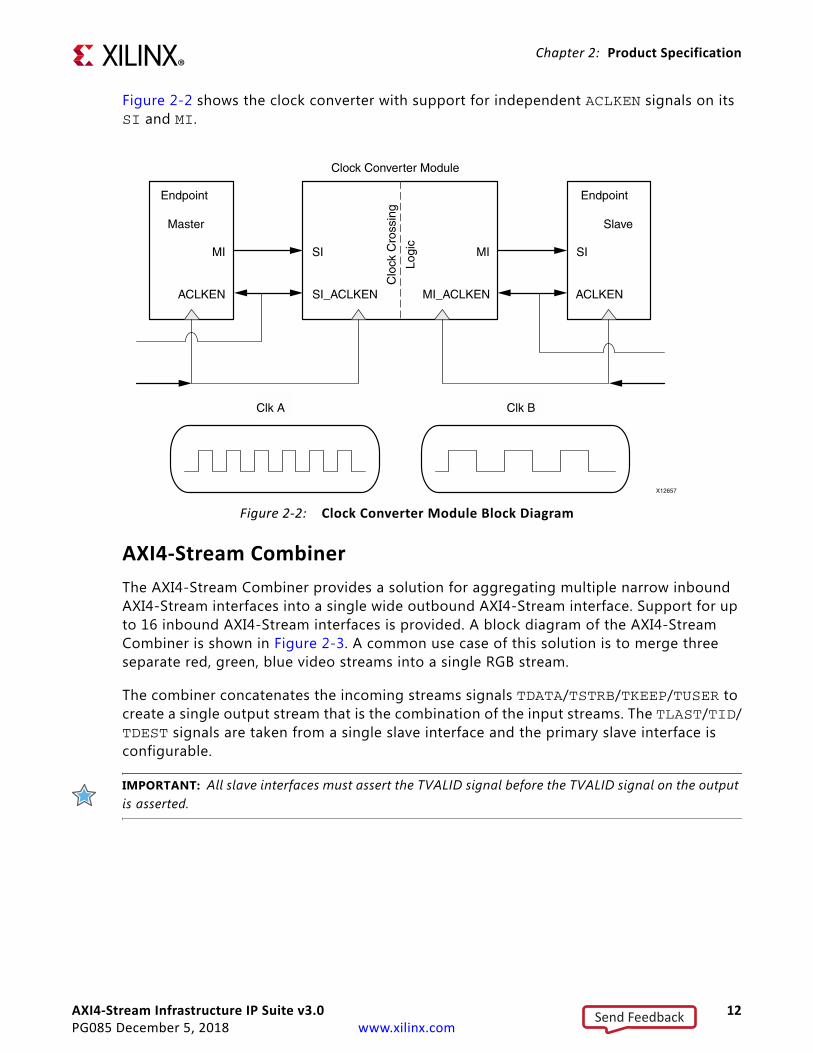
AXI4-Stream Clock Converter
Clock converters are necessary in the AXI4-Stream protocol for converting masters operating at different clock rates to slaves. Typically, the AXI4-Stream Infrastructure IP should be clocked at the same rate as the fastest slave and devices not running at that same rate need to be converted. Synchronous clock converters are ideal because they have the lowest latency and smaller area. However, they are only viable if both clocks are phase-aligned, integer clock ratios, and the FMAX requirements are able to be met.
Asynchronous clock converters are a generic solution able to handle both synchronous/asynchronous clocks with arbitrary phase alignment. The trade-off is that there is a significant increase in area and latency associated with asynchronous clock converters. If global clock enables are configured, additional logic is generated to handle clock enables independently for each clock domain. There is a Clock converter module available in every datapath and it is instantiated if either the clocks are specified as asynchronous or have different synchronous clock ratios. The Clock converter module performs the following functions:
• A clock-rate reduction module performs integer (N:1) division of the clock rate from its input (SI) side to its output (MI) side.
• A clock-rate acceleration module performs integer (1:N) multiplication of clock rate from its input (SI) to output (MI) side.
• Asynchronous clock rate conversion between the input and output uses Xilinx parameterized macros for automatic constraints generation.
• Clock enable crossing logic that handles different ACLKEN signals per clock domain.
Send Feedback
AXI4-Stream Infrastructure IP Suite v3.0 12PG085 December 5, 2018 www.xilinx.com
Chapter 2: Product Specification
Figure 2-2 shows the clock converter with support for independent ACLKEN signals on its SI and MI.
AXI4-Stream Combiner
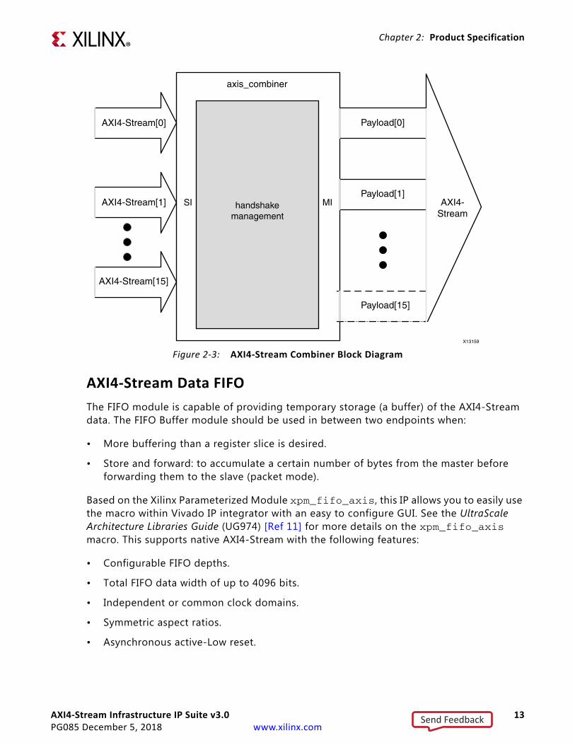
The AXI4-Stream Combiner provides a solution for aggregating multiple narrow inbound AXI4-Stream interfaces into a single wide outbound AXI4-Stream interface. Support for up to 16 inbound AXI4-Stream interfaces is provided. A block diagram of the AXI4-Stream Combiner is shown in Figure 2-3. A common use case of this solution is to merge three separate red, green, blue video streams into a single RGB stream.
The combiner concatenates the incoming streams signals TDATA/TSTRB/TKEEP/TUSER to create a single output stream that is the combination of the input streams. The TLAST/TID/TDEST signals are taken from a single slave interface and the primary slave interface is configurable.
IMPORTANT: All slave interfaces must assert the TVALID signal before the TVALID signal on the output is asserted.
X-Ref Target - Figure 2-2
Figure 2‐2: Clock Converter Module Block Diagram
Send Feedback
AXI4-Stream Infrastructure IP Suite v3.0 13PG085 December 5, 2018 www.xilinx.com
Chapter 2: Product Specification
AXI4-Stream Data FIFO
The FIFO module is capable of providing temporary storage (a buffer) of the AXI4-Stream data. The FIFO Buffer module should be used in between two endpoints when:
• More buffering than a register slice is desired.
• Store and forward: to accumulate a certain number of bytes from the master before forwarding them to the slave (packet mode).
Based on the Xilinx Parameterized Module xpm_fifo_axis, this IP allows you to easily use the macro within Vivado IP integrator with an easy to configure GUI. See the UltraScale Architecture Libraries Guide (UG974) [Ref 11] for more details on the xpm_fifo_axis macro. This supports native AXI4-Stream with the following features:
• Configurable FIFO depths.
• Total FIFO data width of up to 4096 bits.
• Independent or common clock domains.
• Symmetric aspect ratios.
• Asynchronous active-Low reset.
X-Ref Target - Figure 2-3
Figure 2‐3: AXI4-Stream Combiner Block Diagram
Send Feedback

AXI4-Stream Infrastructure IP Suite v3.0 14PG085 December 5, 2018 www.xilinx.com
Chapter 2: Product Specification
• Selectable memory type. Distributed RAMs are suitable for shallow depths and only consume LUTs/Registers. Block RAMs are suitable for medium depth FIFOs and consume only block RAM resources. UltraRAMs are best for very deep FIFOs, but are limited to certain architectures and cannot use independent master/slave clocks.
• ECC support for single-bit error correction, and double-bit error detection. Optional error injection for debug.
• FIFO Flags including almost full/empty, and programmable full/empty.
• Data counts for both writes (synchronous to s_axis clock) and reads (synchronous to m_axis clock) interfaces.
AXI4-Stream Data Width Converter
Data width converters (upsizer/downsizer) are required when interfacing different data width cores with each other. One data width conversion module is available to handle all supported combinations of data widths.
The conversion follows the AMBA® AXI4-Stream Protocol Specification with regards to ordering and expansion of TUSER bits. The width converter does not process any special TUSER encoding formats; it only maps TUSER bits across the width conversion function using the algorithm specified in the AXI4-Stream protocol specification. Depending on the usage/meaning of TUSER to the endpoint IP, additional external logic might be required to manipulate TUSER bits that have been transformed by the width converter.
IMPORTANT: The number of TUSER bits per TDATA bytes must remain constant between input and output.
Up-conversion requires that each incoming beat that is composed of the new larger beat consists of identical TID and TDEST bits and no intermediate TLAST assertions. Partial data may be flushed when either the TLAST bit is received or TID/TDEST changes before enough data is accumulated to send out a complete beat. Unassigned bytes are flushed out as null bytes.
RECOMMENDED: Monitor the TKEEP signal output if TID/TDEST/TLAST signal is present.
Any non-integer multiple byte ratio conversion (N:M) is accomplished by calculating the lowest common multiple (LCM) of N and M and then up-converting from N:LCM then down-converting from LCM:M.
Up-conversion features:
• Range: Input 1-256 Bytes, Output 2-512 Bytes
• Supports full range of 1:N byte ratio conversions
• Minimum latency of 2 + N clock cycles in 1:N byte ratio up-conversion.
Send Feedback
AXI4-Stream Infrastructure IP Suite v3.0 15PG085 December 5, 2018 www.xilinx.com
Chapter 2: Product Specification
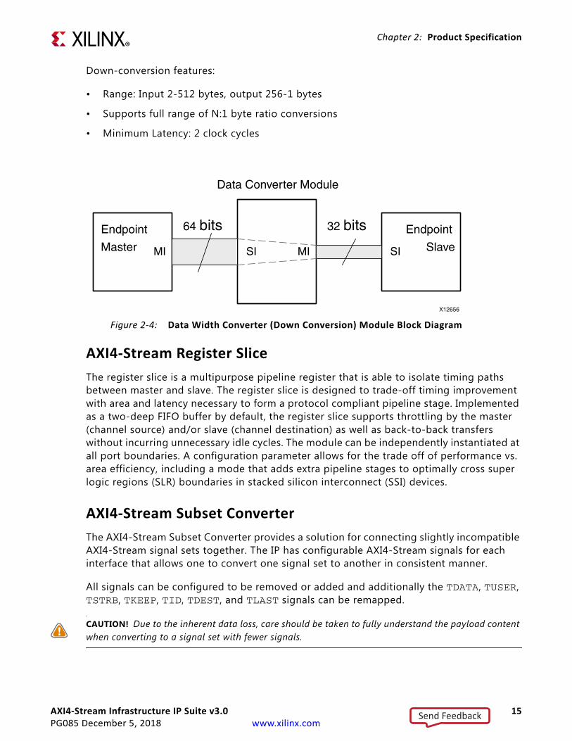
Down-conversion features:
• Range: Input 2-512 bytes, output 256-1 bytes
• Supports full range of N:1 byte ratio conversions
• Minimum Latency: 2 clock cycles
AXI4-Stream Register Slice
The register slice is a multipurpose pipeline register that is able to isolate timing paths between master and slave. The register slice is designed to trade-off timing improvement with area and latency necessary to form a protocol compliant pipeline stage. Implemented as a two-deep FIFO buffer by default, the register slice supports throttling by the master (channel source) and/or slave (channel destination) as well as back-to-back transfers without incurring unnecessary idle cycles. The module can be independently instantiated at all port boundaries. A configuration parameter allows for the trade off of performance vs. area efficiency, including a mode that adds extra pipeline stages to optimally cross super logic regions (SLR) boundaries in stacked silicon interconnect (SSI) devices.
AXI4-Stream Subset Converter
The AXI4-Stream Subset Converter provides a solution for connecting slightly incompatible AXI4-Stream signal sets together. The IP has configurable AXI4-Stream signals for each interface that allows one to convert one signal set to another in consistent manner.
All signals can be configured to be removed or added and additionally the TDATA, TUSER, TSTRB, TKEEP, TID, TDEST, and TLAST signals can be remapped.
CAUTION! Due to the inherent data loss, care should be taken to fully understand the payload content when converting to a signal set with fewer signals.
X-Ref Target - Figure 2-4
Figure 2‐4: Data Width Converter (Down Conversion) Module Block Diagram
Send Feedback
AXI4-Stream Infrastructure IP Suite v3.0 16PG085 December 5, 2018 www.xilinx.com
Chapter 2: Product Specification
When signals are added, they are assigned default values as specified by the AMBA specification. The TLAST signal can be added with a configurable assertion counter that allows one to packetize their data. The REMAP functionality can be used to re-order TDATA bytes when working with core that have slightly different notations for data storage and propagation.
AXI4-Stream Switch
The AXI4-Stream Switch provides configurable routing between masters and slaves. It supports up to 16 masters and 16 slaves, two routing options, and multiple arbitration options.
The two routing options available are TDEST routing and control register routing. The TDEST based routing uses RTL parameters configured before synthesis to control the routing. Each master interface is assigned a base/high TDEST pair that is used to generate a decode table. Each slave interface decodes the incoming transfer based on the valid TDEST value and routes a request to an arbiter of one of the master interfaces. When the arbiter responds with a grant, then the slave interface proceeds with the transfer. Arbitration can be performed at the transfer level or at the transaction level. (A transaction is a series of two or more transfers.) Transaction level arbitration can be set to either arbitrate at either fixed lengths or at TLAST boundaries. An optional timeout option is available that terminates the transaction before the fixed length or TLAST is received if the connection is idle for too long. This can help avoid deadlock in certain system topologies. TDEST based routing requires that the signal has at least log2(Number of Slave Interfaces) number of bits.
Control register routing introduces an AXI4-Lite interface to configure the routing table. There is one register for each of the master interfaces to control each of the selectors. Once the registers have been programmed, a commit register transfers the programmed values from the register interface into the switch. During this period, the AXI4-Stream interfaces are held in reset. This routing mode requires that there is precisely only one path between master and slave. When attempting to map the same slave interface to multiple master interfaces, only the lowest master interface is able to access the slave interface. Unused master interfaces may be disabled and any unmapped slave interfaces are disabled.
Sparse connectivity between slave and master interfaces can be configured. This allows resources to be conserved when they are not needed or to prevent invalid routes. For each slave interface and master interface, a grid is created to allow you to deselect connectivity during IP configuration. Invalid routes stall if using control register based routing and drop transfers in the TDEST based routing. When transfers are dropped, the appropriate decode_err signal is asserted.
Send Feedback
AXI4-Stream Infrastructure IP Suite v3.0 17PG085 December 5, 2018 www.xilinx.com
Chapter 2: Product Specification
StandardsThe IP cores have bus interfaces that comply with the Arm® AMBA AXI4-Stream Protocol Specification Version 1.0.
PerformanceThe performance of an AXI4-Stream Infrastructure IP core is limited only by the FPGA logic speed. Each core utilizes only block RAMs, LUTs, and registers and contains no I/O elements. The values presented in this section should be used as an estimation guideline, actual performance can vary.
Maximum Frequencies
Each core is designed to meet the maximum target frequency of 250 MHz on a Kintex®-7 FPGA (xc7k325tffg900-1.) It can be expected that an -2 speed grade part can achieve 5% higher maximum target frequency and that a -3 speed grade part can achieve 10% higher maximum target frequency. For AXI4-Stream Switch configurations with more than approximately four masters or slaves, the target maximum frequency can be reduced by 20-25%.
Latency
The latency in the IP cores can vary on an interface-to-interface basis, depending on how the IP cores are configured. The latency is calculated in clocked cycles and is measured as the time that it takes from the assertion of the slave interface TVALID signal to the first assertion of the master interface TVALID signal. The latency for each of the individual modules is listed in Table 2-1. To obtain the minimum latency for the system, add up the values shown in the following tables for the modules in your system. The latency specifications assume that the master interface TREADY signal input is always asserted. The back-to-back delay is the number of clock cycles that back-to-back transfers can be accepted by the module. This can be observed by counting how many cycles slave interface TREADY is Low after a transfer is accepted on the interface.
Send Feedback

AXI4-Stream Infrastructure IP Suite v3.0 18PG085 December 5, 2018 www.xilinx.com
Chapter 2: Product Specification
Table 2‐1: Latency by Module Type
Module TypeLatency (Clocks)
Back-to-Back Delay
(Clocks)
Description
AXI4-Stream Broadcaster
0 0 The datapath of the broadcaster is combinatorial. It exhibits no latency if all M_AXIS interfaces have TREADY asserted.
AXI4-Stream Clock Converter (synchronous, speed-up)
1 0 The synchronous clock converter latency is reported as units of the slave interface clock.
AXI4-Stream Clock Converter (synchronous, speed-down)
1 [clock ratio]-1
The synchronous clock converter latency is reported as units of the slave interface clock. The back-to-back delay varies based on the clock ratio. Example: If using a synchronous 150 MHz-to-50 MHz 3:1 clock converter (clock ratio of 3), the back-to-back delay is 2 clock cycles.
AXI4-Stream Clock Converter (asynchronous)
Not Defined
0 The latency associated with an asynchronous clock converter can vary greatly depending on the clocks. It can be expected to see latencies of 5 clock cycles or more.
AXI4-Stream Combiner
0 0 The datapath of the Combiner module is combinatorial and thus has no latency if all ready/valid inputs are asserted.
AXI4-Stream Data FIFO TBD 0 The FIFO when configured in normal mode outputs data as soon as it is possible.
AXI4-Stream Data FIFO (packet mode)
Until TLAST is received or FIFO is full.
0 When configured in packet mode, the FIFO outputs data only when a TLAST is received or the FIFO has filled.
AXI4-Stream Data Width Converter (upsizer)
[data width ratio]
0 The latency varies based on the data width ratio. Example: If a 32 to 128-bit data converter is used (1:4 ratio), the latency of the module is 4 clock cycles.
AXI4-Stream Data Width Converter (downsizer)
1 [data width
ratio]-1
The back-to-back delay varies based on the data width ratio. Example: If a 32 to 16-bit data converter is used (2:1 ratio), then the module can only accept transfers every other cycle.
AXI4-Stream Register Slice (default or Fully-registered mode)
1 0 Adding a register slice adds one cycle of latency. There is no back-to-back delay.
AXI4-Stream Register Slice Lightweight mode
1 1 Adding a register slice adds one cycle of latency. Light-weight mode inserts one bubble cycle after each transfer.
AXI4-Stream Register Slice SLR Crossing mode
3 0 SLR Crossing mode incurs 3 latency cycles and adds no back-to-back delay.
AXI4-Stream Register Slice SLR TDM Crossing mode
3 0 SLR TDM Crossing mode incurs 3 aclk latency cycles and adds no back-to-back delay.
AXI4-Stream Register Slice Bypass mode
0 0 Bypass mode directly connects the SI to the MI.
Send Feedback
AXI4-Stream Infrastructure IP Suite v3.0 19PG085 December 5, 2018 www.xilinx.com
Chapter 2: Product Specification
Throughput
The throughput of a datapath through each AXI4-Stream Infrastructure IP is calculated as TDATA width x clock frequency of each of the paths determined by the SI interface, and MI interface. The minimum throughput of an individual path in a system for which the transfer will traverse determines the overall throughput of the datapath.
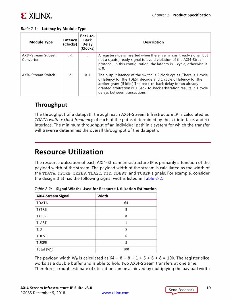
Resource UtilizationThe resource utilization of each AXI4-Stream Infrastructure IP is primarily a function of the payload width of the stream. The payload width of the stream is calculated as the width of the TDATA, TSTRB, TKEEP, TLAST, TID, TDEST, and TUSER signals. For example, consider the design that has the following signal widths listed in Table 2-2.
The payload width WP is calculated as 64 + 8 + 8 + 1 + 5 + 6 + 8 = 100. The register slice works as a double buffer and is able to hold two AXI4-Stream transfers at one time. Therefore, a rough estimate of utilization can be achieved by multiplying the payload width
AXI4-Stream Subset Converter
0-1 0 A register slice is inserted when there is a m_axis_tready signal, but not a s_axis_tready signal to avoid violation of the AXI4-Stream protocol. In this configuration, the latency is 1 cycle, otherwise it is 0.
AXI4-Stream Switch 2 0-1 The output latency of the switch is 2 clock cycles. There is 1 cycle of latency for the TDEST decode and 1 cycle of latency for the arbiter grant (if idle.) The back-to-back delay for an already granted arbitration is 0. Back-to-back arbitration results in 1 cycle delays between transactions.
Table 2‐1: Latency by Module Type
Module TypeLatency (Clocks)
Back-to-Back Delay
(Clocks)
Description
Table 2‐2: Signal Widths Used for Resource Utilization Estimation
AXI4-Stream Signal Width
TDATA 64
TSTRB 8
TKEEP 8
TLAST 1
TID 5
TDEST 6
TUSER 8
Total (Wp) 100
Send Feedback
AXI4-Stream Infrastructure IP Suite v3.0 20PG085 December 5, 2018 www.xilinx.com
Chapter 2: Product Specification
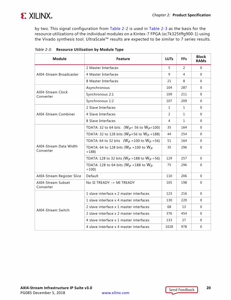
by two. This signal configuration from Table 2-2 is used in Table 2-3 as the basis for the resource utilizations of the individual modules on a Kintex-7 FPGA (xc7k325tffg900-1) using the Vivado synthesis tool. UltraScale™ results are expected to be similar to 7 series results.
Table 2‐3: Resource Utilization by Module Type
Module Feature LUTs FFsBlock RAMs
AXI4-Stream Broadcaster
2 Master Interfaces 5 2 0
4 Master Interfaces 9 4 0
8 Master Interfaces 21 8 0
AXI4-Stream Clock Converter
Asynchronous 104 287 0
Synchronous 2:1 109 211 0
Synchronous 1:2 107 209 0
AXI4-Stream Combiner
2 Slave Interfaces 1 1 0
4 Slave Interfaces 2 1 0
8 Slave Interfaces 4 1 0
AXI4-Stream Data Width Converter
TDATA: 32 to 64 bits (WP= 56 to WP=100) 35 164 0
TDATA: 32 to 128 bits (WP=56 to WP =188) 44 254 0
TDATA: 64 to 32 bits (WP =100 to WP =56) 51 164 0
TDATA: 64 to 128 bits (WP =100 to WP =188)
35 296 0
TDATA: 128 to 32 bits (WP =188 to WP =56) 129 257 0
TDATA: 128 to 64 bits (WP =188 to WP =100)
75 296 0
AXI4-Stream Register Slice Default 110 206 0
AXI4-Stream Subset Converter
No SI TREADY -> MI TREADY 105 198 0
AXI4-Stream Switch
1 slave interface x 2 master interfaces 123 216 0
1 slave interface x 4 master interfaces 130 220 0
2 slave interface x 1 master interfaces 68 13 0
2 slave interface x 2 master interfaces 376 454 0
4 slave interface x 1 master interfaces 133 27 0
4 slave interface x 4 master interfaces 1028 978 0
Send Feedback
AXI4-Stream Infrastructure IP Suite v3.0 21PG085 December 5, 2018 www.xilinx.com
Chapter 2: Product Specification
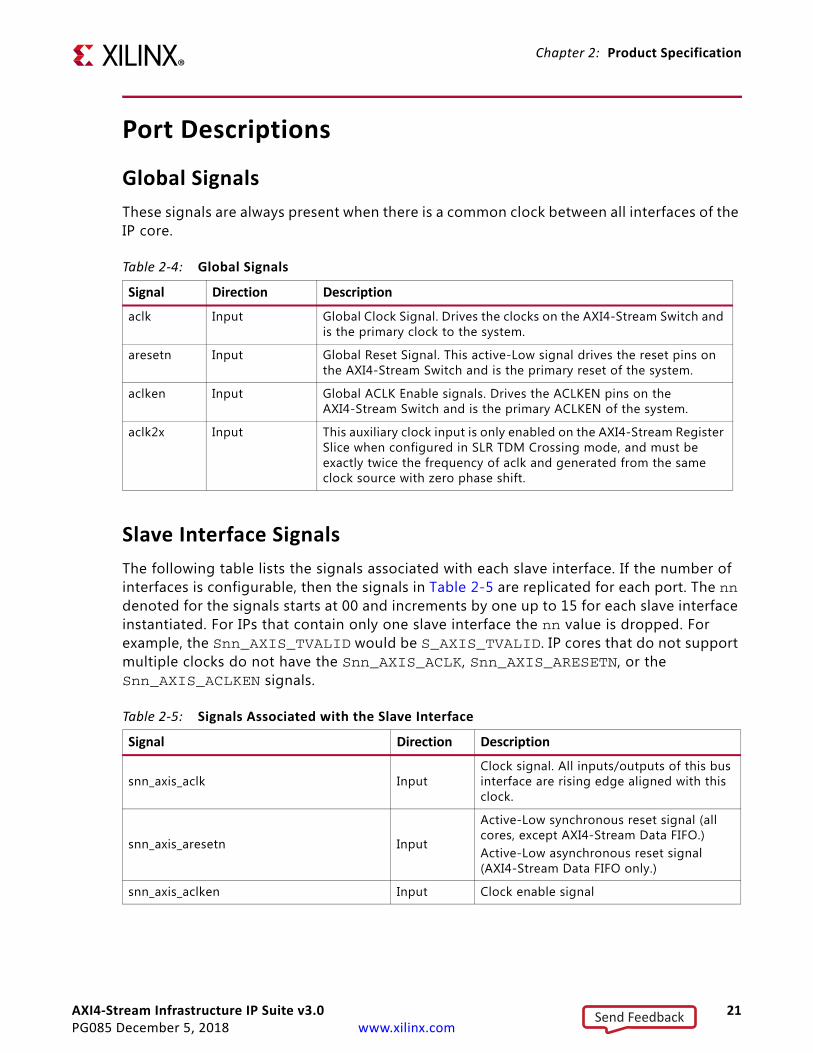
Port Descriptions
Global Signals
These signals are always present when there is a common clock between all interfaces of the IP core.
Slave Interface Signals
The following table lists the signals associated with each slave interface. If the number of interfaces is configurable, then the signals in Table 2-5 are replicated for each port. The nn denoted for the signals starts at 00 and increments by one up to 15 for each slave interface instantiated. For IPs that contain only one slave interface the nn value is dropped. For example, the Snn_AXIS_TVALID would be S_AXIS_TVALID. IP cores that do not support multiple clocks do not have the Snn_AXIS_ACLK, Snn_AXIS_ARESETN, or the Snn_AXIS_ACLKEN signals.
Table 2‐4: Global Signals
Signal Direction Description
aclk Input Global Clock Signal. Drives the clocks on the AXI4-Stream Switch and is the primary clock to the system.
aresetn Input Global Reset Signal. This active-Low signal drives the reset pins on the AXI4-Stream Switch and is the primary reset of the system.
aclken Input Global ACLK Enable signals. Drives the ACLKEN pins on the AXI4-Stream Switch and is the primary ACLKEN of the system.
aclk2x Input This auxiliary clock input is only enabled on the AXI4-Stream Register Slice when configured in SLR TDM Crossing mode, and must be exactly twice the frequency of aclk and generated from the same clock source with zero phase shift.
Table 2‐5: Signals Associated with the Slave Interface
Signal Direction Description
snn_axis_aclk InputClock signal. All inputs/outputs of this bus interface are rising edge aligned with this clock.
snn_axis_aresetn Input
Active-Low synchronous reset signal (all cores, except AXI4-Stream Data FIFO.) Active-Low asynchronous reset signal (AXI4-Stream Data FIFO only.)
snn_axis_aclken Input Clock enable signal
Send Feedback

AXI4-Stream Infrastructure IP Suite v3.0 22PG085 December 5, 2018 www.xilinx.com
Chapter 2: Product Specification
snn_axis_tvalid(1) Input
TVALID indicates that the master is driving a valid transfer.A transfer takes place when both TVALID and TREADY are asserted.
snn_axis_tready(1) Output TREADY indicates that the slave can accept a transfer in the current cycle.
snn_axis_tdata[(C_MNN_AXIS_TDATA_WIDTH-1):0](1) Input
TDATA is the primary payload that is used to provide the data that is passing across the interface. The width of the data payload is an integer number of bytes.
snn_axis_tstrb[((C_MNN_AXIS_TDATA_WIDTH/8)-1):0](1) Input
TSTRB is the byte qualifier that indicates whether the content of the associated byte of TDATA is processed as a data byte or a position byte.
snn_axis_tkeep[((C_MNN_AXIS_TDATA_WIDTH/8)-1):0](1) Input
TKEEP is the byte qualifier that indicates whether the content of the associated byte of TDATA is processed as part of the data stream.Associated bytes that have the TKEEP byte qualifier deasserted are null bytes and can be removed from the data stream.
snn_axis_tlast(1) Input TLAST indicates the boundary of a packet.
snn_axis_tid[C_NATIVE_TID_WIDTH-1:0](1) Input TID is the data stream identifier that
indicates different streams of data.
snn_axis_tdest[(C_NATIVE_TDATA_WIDTH-1):0](1) Input TDEST provides routing information for the
data stream.
snn_axis_tuser[(C_SNN_AXIS_TUSER_WIDTH-1):0](1) Input
TUSER is user-defined sideband information that can be transmitted alongside the data stream.
s_req_suppress[C_NUM_SI_SLOTS-1:0] Input
AXI4-Stream Switch only signal. Active-High signal to skip this bus on the next arbitration cycle. While the signal is asserted, this bus does not receive the next arbitration. If this bus already has arbitration granted, it remains granted until the arbitration cycle is completely normally.
s_decode_err[C_NUM_SI_SLOTS-1:0] Output
AXI4-Stream Switch only signal. One-hot output indicates that a incoming transfer has a TDEST value that not map to a valid Master Interface. Invalid TDEST transfers are dropped. Only valid if the TDEST signal is present and used for routing.
Table 2‐5: Signals Associated with the Slave Interface (Cont’d)
Signal Direction Description
Send Feedback
AXI4-Stream Infrastructure IP Suite v3.0 23PG085 December 5, 2018 www.xilinx.com
Chapter 2: Product Specification
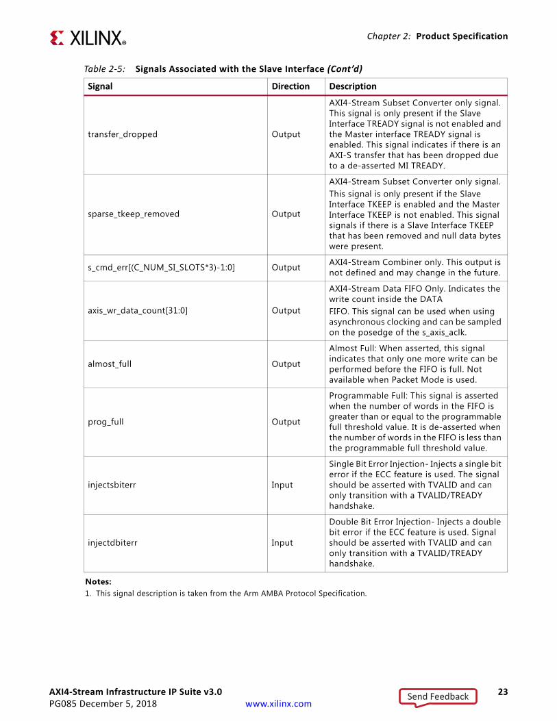
transfer_dropped Output
AXI4-Stream Subset Converter only signal. This signal is only present if the Slave Interface TREADY signal is not enabled and the Master interface TREADY signal is enabled. This signal indicates if there is an AXI-S transfer that has been dropped due to a de-asserted MI TREADY.
sparse_tkeep_removed Output
AXI4-Stream Subset Converter only signal.This signal is only present if the Slave Interface TKEEP is enabled and the Master Interface TKEEP is not enabled. This signal signals if there is a Slave Interface TKEEP that has been removed and null data bytes were present.
s_cmd_err[(C_NUM_SI_SLOTS*3)-1:0] Output AXI4-Stream Combiner only. This output is not defined and may change in the future.
axis_wr_data_count[31:0] Output
AXI4-Stream Data FIFO Only. Indicates the write count inside the DATAFIFO. This signal can be used when using asynchronous clocking and can be sampled on the posedge of the s_axis_aclk.
almost_full Output
Almost Full: When asserted, this signal indicates that only one more write can be performed before the FIFO is full. Not available when Packet Mode is used.
prog_full Output
Programmable Full: This signal is asserted when the number of words in the FIFO is greater than or equal to the programmable full threshold value. It is de-asserted when the number of words in the FIFO is less than the programmable full threshold value.
injectsbiterr Input
Single Bit Error Injection- Injects a single bit error if the ECC feature is used. The signal should be asserted with TVALID and can only transition with a TVALID/TREADY handshake.
injectdbiterr Input
Double Bit Error Injection- Injects a double bit error if the ECC feature is used. Signal should be asserted with TVALID and can only transition with a TVALID/TREADY handshake.
Notes: 1. This signal description is taken from the Arm AMBA Protocol Specification.
Table 2‐5: Signals Associated with the Slave Interface (Cont’d)
Signal Direction Description
Send Feedback

AXI4-Stream Infrastructure IP Suite v3.0 24PG085 December 5, 2018 www.xilinx.com
Chapter 2: Product Specification
Master Interface Signals
Table 2-6 lists the signals associated with each master interface. If the number of interfaces is configurable, the signals are then replicated for each port. The nn denoted for the signals starts at 00 and increments by one up to 15 for each master interface instantiated. For IPs that contain only one master interface the nn value is dropped. For example, the Mnn_AXIS_TVALID would be M_AXIS_TVALID. IPs that do not support multiple clocks do not have the Mnn_AXIS_ACLK, Mnn_AXIS_ARESETN, or the Mnn_AXIS_ACLKEN signals.
Table 2‐6: Signals Associated with the Master Interface
Signal Direction Description
mnn_axis_aclk Input Clock signal. All inputs/outputs of this bus interface are rising edge aligned with this clock.
mnn_axis_aresetn Input Active-Low synchronous reset signal
mnn_axis_aclken Input Clock enable signal
mnn_axis_tvalid(1) Output
TVALID indicates that the master is driving a valid transfer.A transfer takes place when both TVALID and TREADY are asserted.
mnn_axis_tready(1) Input TREADY indicates that the slave can accept a transfer in the current cycle.
mnn_axis_tdata[(c_mnn_axis_tdata_width-1):0](1) Output
TDATA is the primary payload that is used to provide the data that is passing across the interface. The width of the data payload is an integer number of bytes.
mnn_axis_tstrb[((c_mnn_axis_tdata_width/8)-1):0](1) Output
TSTRB is the byte qualifier that indicates whether the content of the associated byte of TDATA is processed as a data byte or a position byte.
mnn_axis_tkeep[((c_mnn_axis_tdata_width/8)-1):0](1) Output
TKEEP is the byte qualifier that indicates whether the content of the associated byte of TDATA is processed as part of the data stream.Associated bytes that have the TKEEP byte qualifier deasserted are null bytes and can be removed from the data stream.
mnn_axis_tlast(1) Output TLAST indicates the boundary of a packet.
mnn_axis_tid[c_native_tid_width-1:0](1) Output TID is the data stream identifier that
indicates different streams of data.
mnn_axis_tdest[(c_native_tdata_width-1):0](1) Output TDEST provides routing information for
the data stream.
Send Feedback
AXI4-Stream Infrastructure IP Suite v3.0 25PG085 December 5, 2018 www.xilinx.com
Chapter 2: Product Specification
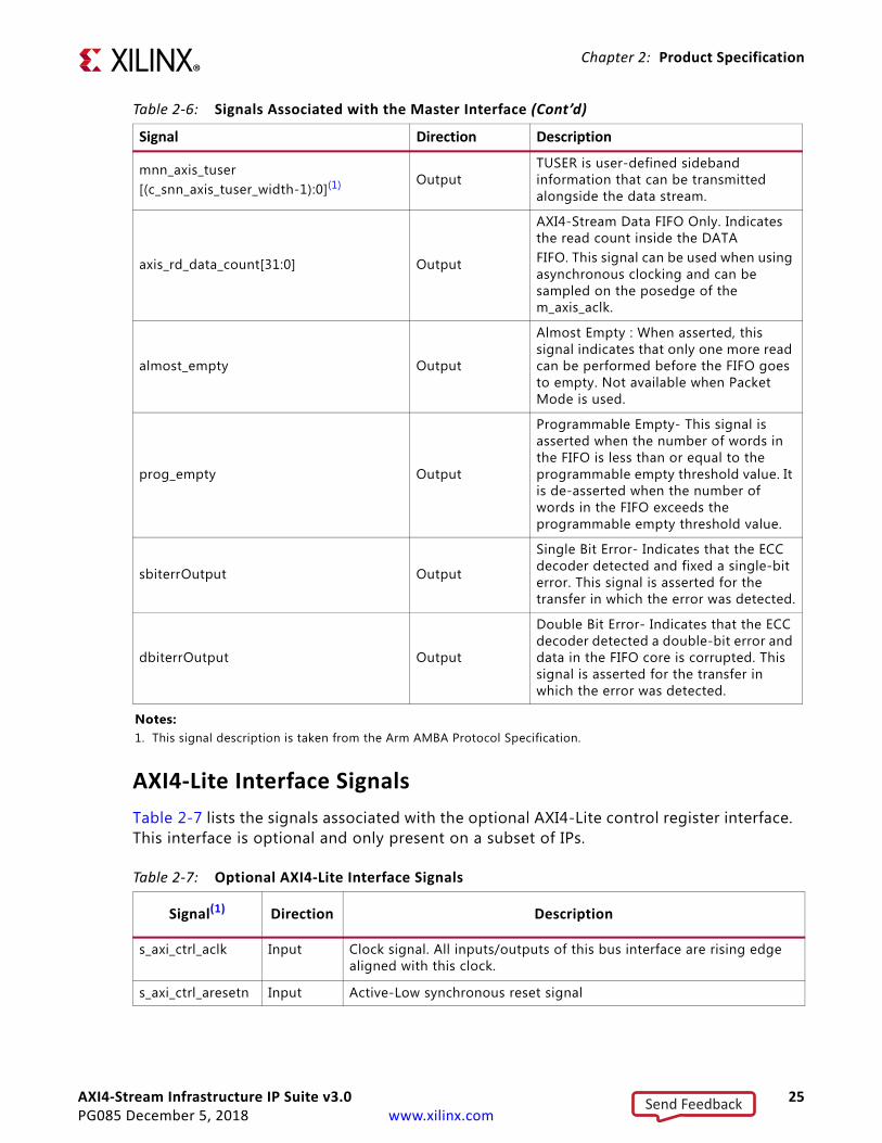
AXI4-Lite Interface Signals
Table 2-7 lists the signals associated with the optional AXI4-Lite control register interface. This interface is optional and only present on a subset of IPs.
mnn_axis_tuser[(c_snn_axis_tuser_width-1):0](1) Output
TUSER is user-defined sideband information that can be transmitted alongside the data stream.
axis_rd_data_count[31:0] Output
AXI4-Stream Data FIFO Only. Indicates the read count inside the DATAFIFO. This signal can be used when using asynchronous clocking and can be sampled on the posedge of the m_axis_aclk.
almost_empty Output
Almost Empty : When asserted, this signal indicates that only one more read can be performed before the FIFO goes to empty. Not available when Packet Mode is used.
prog_empty Output
Programmable Empty- This signal is asserted when the number of words in the FIFO is less than or equal to the programmable empty threshold value. It is de-asserted when the number of words in the FIFO exceeds the programmable empty threshold value.
sbiterrOutput Output
Single Bit Error- Indicates that the ECC decoder detected and fixed a single-bit error. This signal is asserted for the transfer in which the error was detected.
dbiterrOutput Output
Double Bit Error- Indicates that the ECC decoder detected a double-bit error and data in the FIFO core is corrupted. This signal is asserted for the transfer in which the error was detected.
Notes: 1. This signal description is taken from the Arm AMBA Protocol Specification.
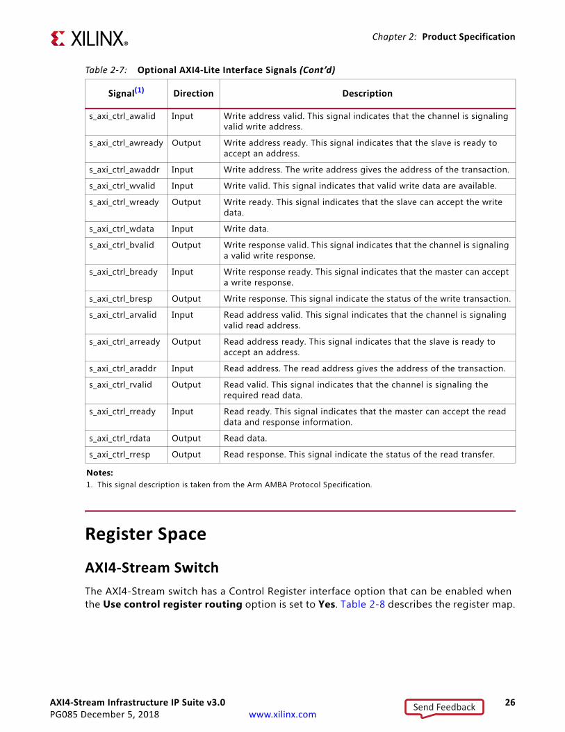
Table 2‐7: Optional AXI4-Lite Interface Signals
Signal(1) Direction Description
s_axi_ctrl_aclk Input Clock signal. All inputs/outputs of this bus interface are rising edge aligned with this clock.
s_axi_ctrl_aresetn Input Active-Low synchronous reset signal
Table 2‐6: Signals Associated with the Master Interface (Cont’d)
Signal Direction Description
Send Feedback
AXI4-Stream Infrastructure IP Suite v3.0 26PG085 December 5, 2018 www.xilinx.com
Chapter 2: Product Specification
Register Space
AXI4-Stream Switch
The AXI4-Stream switch has a Control Register interface option that can be enabled when the Use control register routing option is set to Yes. Table 2-8 describes the register map.
s_axi_ctrl_awalid Input Write address valid. This signal indicates that the channel is signaling valid write address.
s_axi_ctrl_awready Output Write address ready. This signal indicates that the slave is ready to accept an address.
s_axi_ctrl_awaddr Input Write address. The write address gives the address of the transaction.
s_axi_ctrl_wvalid Input Write valid. This signal indicates that valid write data are available.
s_axi_ctrl_wready Output Write ready. This signal indicates that the slave can accept the write data.
s_axi_ctrl_wdata Input Write data.
s_axi_ctrl_bvalid Output Write response valid. This signal indicates that the channel is signaling a valid write response.
s_axi_ctrl_bready Input Write response ready. This signal indicates that the master can accept a write response.
s_axi_ctrl_bresp Output Write response. This signal indicate the status of the write transaction.
s_axi_ctrl_arvalid Input Read address valid. This signal indicates that the channel is signaling valid read address.
s_axi_ctrl_arready Output Read address ready. This signal indicates that the slave is ready to accept an address.
s_axi_ctrl_araddr Input Read address. The read address gives the address of the transaction.
s_axi_ctrl_rvalid Output Read valid. This signal indicates that the channel is signaling the required read data.
s_axi_ctrl_rready Input Read ready. This signal indicates that the master can accept the read data and response information.
s_axi_ctrl_rdata Output Read data.
s_axi_ctrl_rresp Output Read response. This signal indicate the status of the read transfer.
Notes: 1. This signal description is taken from the Arm AMBA Protocol Specification.
Table 2‐7: Optional AXI4-Lite Interface Signals (Cont’d)
Signal(1) Direction Description
Send Feedback
AXI4-Stream Infrastructure IP Suite v3.0 27PG085 December 5, 2018 www.xilinx.com
Chapter 2: Product Specification
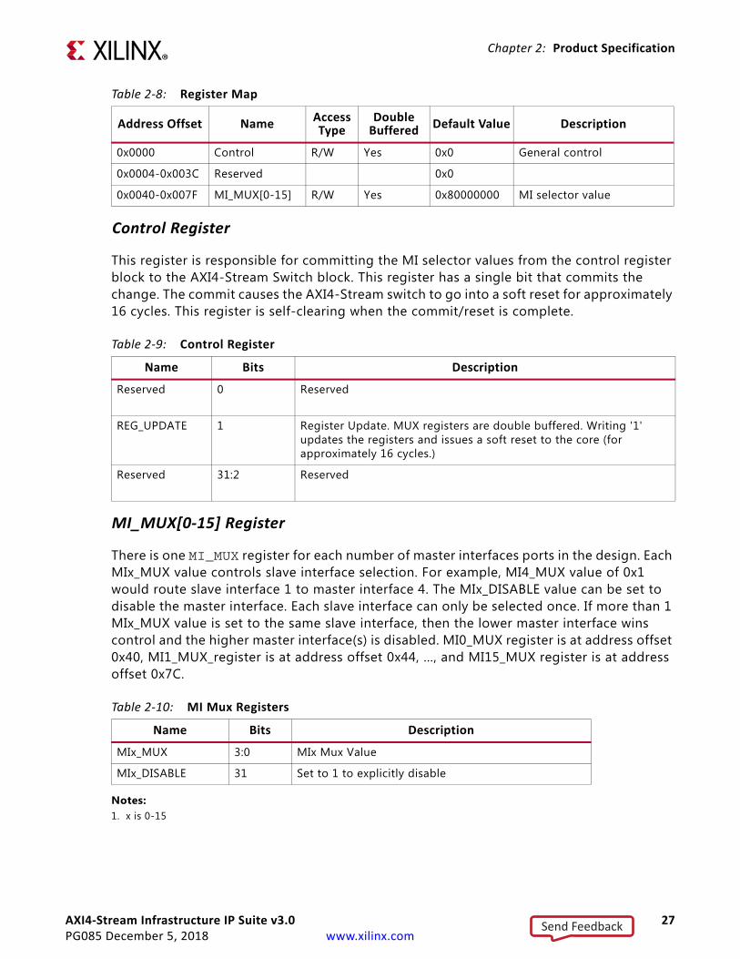
Control Register
This register is responsible for committing the MI selector values from the control register block to the AXI4-Stream Switch block. This register has a single bit that commits the change. The commit causes the AXI4-Stream switch to go into a soft reset for approximately 16 cycles. This register is self-clearing when the commit/reset is complete.
MI_MUX[0-15] Register
There is one MI_MUX register for each number of master interfaces ports in the design. Each MIx_MUX value controls slave interface selection. For example, MI4_MUX value of 0x1 would route slave interface 1 to master interface 4. The MIx_DISABLE value can be set to disable the master interface. Each slave interface can only be selected once. If more than 1 MIx_MUX value is set to the same slave interface, then the lower master interface wins control and the higher master interface(s) is disabled. MI0_MUX register is at address offset 0x40, MI1_MUX_register is at address offset 0x44, …, and MI15_MUX register is at address offset 0x7C.
Notes: 1. x is 0-15
Table 2‐8: Register Map
Address Offset NameAccess Type
Double Buffered Default Value Description
0x0000 Control R/W Yes 0x0 General control
0x0004-0x003C Reserved 0x0
0x0040-0x007F MI_MUX[0-15] R/W Yes 0x80000000 MI selector value
Table 2‐9: Control Register
Name Bits Description
Reserved 0 Reserved
REG_UPDATE 1 Register Update. MUX registers are double buffered. Writing '1' updates the registers and issues a soft reset to the core (for approximately 16 cycles.)
Reserved 31:2 Reserved
Table 2‐10: MI Mux Registers
Name Bits Description
MIx_MUX 3:0 MIx Mux Value
MIx_DISABLE 31 Set to 1 to explicitly disable
Send Feedback
AXI4-Stream Infrastructure IP Suite v3.0 28PG085 December 5, 2018 www.xilinx.com
Chapter 2: Product Specification
Usage
To configure a 4x4 switch where MI0 is sourced from SI1, MI1 is unused, MI2 is sourced from SI3 and MI3 is sourced from SI0, use the following code example:
# Setup registersWrite address offset 0x40, Data 0x1Write address offset 0x44, Data 0x8000_0000Write address offset 0x48, Data 0x3Write address offset 0x4C, Data 0x0 # Commit registersWrite address offset 0x0, data 0x2
Send Feedback
AXI4-Stream Infrastructure IP Suite v3.0 29PG085 December 5, 2018 www.xilinx.com
Chapter 3
Designing with the CoreThis chapter includes guidelines and additional information to make designing with the core easier.
General Design GuidelinesWhen designing systems using AXI4-Stream Infrastructure IP Suite, the first step is to establish the topology of the system. This requires an understanding of the main interface characteristics of each AXI4-Stream master and slave that needs to be able to communicate together. AXI4-Stream masters and slaves then need to be grouped by desired connectivity into a system with one or more AXI4-Stream Infrastructure IP blocks tying them together so they can exchange data.
In general, try to establish the system partitioning/topology to use multiple smaller/simpler interconnects than a single large interconnect, especially in systems with a large number of devices. For example, combinations of N master x 1 slaves interconnects and 1 master x N slave interconnects are generally preferable to MxN interconnects in terms of area, latency, and throughput. MxN interconnect when required for performance or connectivity requirements should try to limit the number of endpoints or specify sparse connectivity to reduce resource utilization.
The Xilinx Vivado AXI Reference Guide (UG1037) [Ref 3] provides information about AXI4-Stream protocol usage guidelines and conventions; much of the AXI system optimizations information described for AXI Interconnect is applicable to AXI4-Stream Infrastructure IP Suite. The Xilinx AXI Reference Guide should be reviewed and consulted before designing or structuring systems around the AXI4-Stream Infrastructure IP.
After the number and topology of AXI4-Stream Infrastructure IP systems have been determined, the next step is to tailor each AXI4-Stream Infrastructure IP system to have the correct set of optional interface signals and set signals’ widths as needed. This sets up the interface signal set for the AXI4-Stream Infrastructure IP to ensure that data can be exchanged and routed as needed across the system.
Finally, the AXI4-Stream Infrastructure IP system should be optimized and fine-tuned to fit its application. This includes tuning FIFOs, width converters, clock converters, arbiters, and register slices (pipeline stages) as needed to balance area, timing, performance, and ease-of-use.
Send Feedback
AXI4-Stream Infrastructure IP Suite v3.0 30PG085 December 5, 2018 www.xilinx.com
Chapter 3: Designing with the Core
ClockingEach AXI4-Stream Infrastructure IP module has a single clock input that must be driven with the exception of AXI4-Stream Clock Converter and AXI4-Stream Data FIFO. These modules allow for different clocks and must have both S_AXIS_ACLK and M_AXIS_ACLK connected.
The AXI4-Stream Clock Converter and Data FIFO allows systems with different clock domains to be designed. AXI4-Stream Clock Converter synchronous mode can be used when the endpoint IP has a phase-aligned, integer multiple clock ratio to the core switch's clock. This is often the case when the same MMCM or PLL is driving synchronous integer ratio clocks because the MMCM/PLL can also ensure phase alignment across their clock outputs. The AXI4-Stream Clock Converter and AXI4-Stream Data FIFO asynchronous clocking mode allows the attached endpoint IP to run at a completely unrelated clock frequency or phase to the core switch clock.
An optional feature for clock enables (ACLKEN ports) allows an extra level of control for essentially gating clocks. The clock enable signals can be used to control which clock edges are seen as real transfer cycles. Clock enables can be used for purposes like preserving global clock buffers, debug by stepping the clock enable to step through operational states in the system, and dynamic power savings. Clock enables can be controlled independently on each interface port and for the core switch.
The optional AXI4-Lite control register interface operates asynchronously from the AXI4-Stream clocks.
Send Feedback
AXI4-Stream Infrastructure IP Suite v3.0 31PG085 December 5, 2018 www.xilinx.com
Chapter 3: Designing with the Core
ResetsThe AXI4-Stream Infrastructure IP Suite provides active-Low reset inputs for every clock input on the IP. Each reset input must be synchronized to the associated ACLK input of the interface. To ensure data is not lost during reset deassertion across multiple interfaces of the AXI4-Stream Infrastructure IP systems (operating in potentially different clock domains), the AXI4-Stream Infrastructure IP deasserts all TREADY and TVALID outputs until the clock cycle after their source logic has internally exited reset. Any endpoint IP driving TREADY or TVALID inputs to the AXI4-Stream Infrastructure IP should also deassert these signals until the clock cycle after they have exited reset internally.
These guidelines ensure that endpoint IPs can internally come out of reset at different times (due to internal reset pipelining) and no data will be exchanged until both are internally out of reset.
RECOMMENDED: Any endpoint should deassert TREADY and TVALID within 8 clock cycles of reset assertion. ARESETn should also be asserted for at least 16 cycles of the slowest system clock to ensure that all AXI4-Stream interfaces in the system enter reset and have time to deassert their TREADY/TVALID outputs before coming back out of reset.
Send Feedback
AXI4-Stream Infrastructure IP Suite v3.0 32PG085 December 5, 2018 www.xilinx.com
Chapter 4
Design Flow StepsThis chapter describes customizing and generating the core, constraining the core, and the simulation, synthesis and implementation steps that are specific to this IP core. More detailed information about the standard Vivado® design flows in the Vivado IP integrator can be found in the following Vivado Design Suite user guides:
• Vivado Design Suite User Guide: Designing IP Subsystems using IP Integrator (UG994) [Ref 9]
• Vivado Design Suite User Guide: Designing with IP (UG896) [Ref 5]
• Vivado Design Suite User Guide: Getting Started (UG910) [Ref 7]
• Vivado Design Suite User Guide: Logic Simulation (UG900) [Ref 8]
Customizing and Generating the CoreThis section includes information about using Xilinx tools to customize and generate the core in the Vivado Design Suite.
If you are customizing and generating the core in the IP integrator, see the Vivado Design Suite User Guide: Designing IP Subsystems using IP Integrator (UG994) [Ref 9] for detailed information. IP integrator might auto-compute certain configuration values when validating or generating the design. To check whether the values do change, see the description of the parameter in this chapter. To view the parameter value, run the validate_bd_design command in the Tcl console.
You can customize the IP for use in your design by specifying values for the various parameters associated with the IP core using the following steps:
1. Select the IP from the IP catalog.
2. Double-click on the selected IP or select the Customize IP command from the toolbar or popup menu.
For details, see the sections, “Working with IP” and “Customizing IP for the Design” in the Vivado Design Suite User Guide: Designing with IP (UG896) [Ref 5] and the “Working with the Vivado IDE” section in the Vivado Design Suite User Guide: Getting Started (UG810) [Ref 7].
Send Feedback
AXI4-Stream Infrastructure IP Suite v3.0 33PG085 December 5, 2018 www.xilinx.com
Chapter 4: Design Flow Steps
If you are customizing and generating the core in the IP integrator, see the Vivado Design Suite User Guide: Designing IP Subsystems Using IP Integrator (UG994) [Ref 9] for detailed information. IP integrator might auto-compute certain configuration values when validating or generating the design. To check whether the values do change, see the description of the parameter in this chapter. To view the parameter value you can run the validate_bd_design command in the Tcl console.
Note: Figures in this chapter are illustrations of the Vivado IDE. This layout might vary from the current version.
Creating a Project
First, create a new project using the Vivado Design Suite. For detailed information on starting and using the Vivado Design Suite, see the Vivado documentation.
Perform the following steps:
1. Start the Vivado Design Suite.
2. Choose File > New Project from the menu.
3. Using the Create New Vivado Project wizard. Click Next.
4. Select a Project Name:
a. Modify the project name, if desired.
b. Specify the Project location using the text box or the directory navigator.
c. Click Next.
5. Select a Project Type:
a. Choose RTL Project.
b. Ensure the "Do not specify sources at this time" checkbox is checked.
c. Click Next.
6. Select the Default Part.
a. Select the target family, device, package, and speed grade.Example: Kintex-7, xc7k325t-ffg900-1
Note: If an unsupported family is selected, the IP core does not appear in the IP catalog.
b. Click Next.
7. Review Project Summary.
a. If the summary does not look correct, click the Back button and resolve the issue.
b. Click Finish to create the project.
After creating the project, the IP cores are available for selection in the IP catalog, located at AXI Infrastructure Taxonomy.
Send Feedback

AXI4-Stream Infrastructure IP Suite v3.0 34PG085 December 5, 2018 www.xilinx.com
Chapter 4: Design Flow Steps
Customizing and Generating the Core
Locate the IP core in the Vivado Design Suite and click it once to select it. Details regarding the solution are displayed in the Details window. To configure the IP, double-click the IP name in the IP catalog.
This launches the customization dialog box. Each dialog box is described in detail in their respective sections.
AXI4-Stream Broadcaster
The AXI4-Stream Broadcaster GUI is shown in Figure 4-1.
Review each of the available options in Figure 4-1 and modify them as desired so that the AXI4-Stream Broadcaster solution meets the requirements of the larger project into which it is integrated. The following subsections discuss the options in detail to serve as a guide.
X-Ref Target - Figure 4-1
Figure 4‐1: AXI4-Stream Broadcaster Customization Dialog Box
Send Feedback
AXI4-Stream Infrastructure IP Suite v3.0 35PG085 December 5, 2018 www.xilinx.com
Chapter 4: Design Flow Steps
Global Parameters
Component Name: The base name of the output files generated for the core. Names must begin with a letter and can be composed of any of the following characters: a to z, 0 to 9, and "_".
Number of Master Interfaces: This parameter specifies the number of AXI4-Stream master interfaces present on the IP. The value can be 2 and 16. AXI4-Stream slave interface transfers are replicated to each of the AXI4-Stream master interfaces specified by this parameter.
Signal Properties
When using Vivado IP integrator, the Vivado IDE automatically computes the values of these parameters.
Enable TREADY: If set to Yes, this parameters specifies if the optional TREADY signal is present on all the AXI4-Stream interfaces. Set to No to omit the signal.
TIP: The AXI4-Stream specification recommends that TREADY is always included.
SI TDATA Width (bytes): This parameter specifies the width in bytes of the TDATA signal on the inbound AXI4-Stream Interface (the Slave Interface). This parameter is an integer and can vary from 0 to 512. Set to 0 to omit the TDATA signal. If the TDATA signal is omitted, then the TKEEP and TSTRB signals are also omitted. The width of the port is multiplied by 8 to get the width in bits.
MI TDATA Width (bytes): This parameter specifies the width in bytes of the TDATA signal on each of the outbound AXI4-Stream Interfaces (the Master Interfaces). This parameter is an integer and can vary from 0 to 512 but it may only be set to 0 if the SI TDATA Width is also 0. When both parameters are set to 0, the TDATA signal is omitted from the interfaces of the IP. If the TDATA signal is omitted, then the TKEEP and TSTRB signals are also omitted. The width of the TDATA signal on each port is multiplied by 8 to get the width in bits. If the MI TDATA Width is not equal to the SI TDATA Width then TKEEP and TSTRB signals should not be enabled.
Enable TSTRB: If set to Yes, this parameters specifies if the optional TSTRB signal is present on all the AXI4-Stream interfaces. This option can only be enabled if the SI and MI TDATA width (bytes) parameter are both greater than 0 and each have the same width value.
Enable TKEEP: If set to Yes, this parameters specifies if the optional TKEEP signal is present on all the AXI4-Stream interfaces. This option can only be enabled if the SI and MI TDATA width (bytes) parameter are both greater than 0 and each have the same width value.
Enable TLAST: If set to Yes, this parameters specifies if the optional TLAST signal is present on all the AXI4-Stream interfaces.
Send Feedback
AXI4-Stream Infrastructure IP Suite v3.0 36PG085 December 5, 2018 www.xilinx.com
Chapter 4: Design Flow Steps
TID Width (bits): If greater than 0, this parameter specifies if the optional TID signal is present on all the AXI4-Stream interfaces. A value of 0 omits this signal. Values 1 and 32 sets the width of this signal accordingly.
TDEST Width (bits): If greater than 0, this parameter specifies if the optional TDEST signal is present on all the AXI4-Stream interfaces. A value of 0 omits this signal. Values 1 and 32 sets the width of this signal accordingly.
TUSER Width (bits): If greater than 0, this parameter specifies if the optional TUSER signal is present on all the AXI4-Stream interfaces. A value of 0 omits this signal. Values 1 and 32 sets the width of this signal accordingly.
Enable ACLKEN: If set to Yes, this parameter specifies if the optional ACLKEN signal is present with all the AXI4-Stream interfaces clocks.
Stream Splitting Options
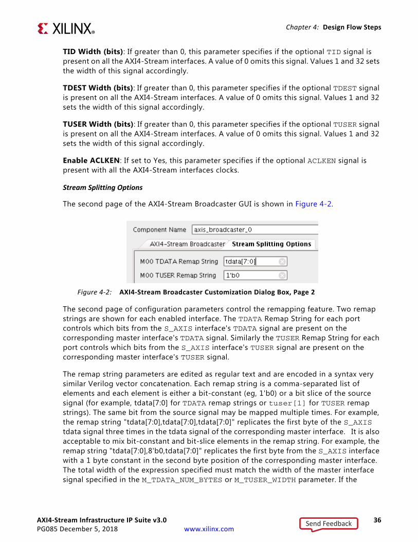
The second page of the AXI4-Stream Broadcaster GUI is shown in Figure 4-2.
The second page of configuration parameters control the remapping feature. Two remap strings are shown for each enabled interface. The TDATA Remap String for each port controls which bits from the S_AXIS interface's TDATA signal are present on the corresponding master interface's TDATA signal. Similarly the TUSER Remap String for each port controls which bits from the S_AXIS interface's TUSER signal are present on the corresponding master interface's TUSER signal.
The remap string parameters are edited as regular text and are encoded in a syntax very similar Verilog vector concatenation. Each remap string is a comma-separated list of elements and each element is either a bit-constant (eg, 1'b0) or a bit slice of the source signal (for example, tdata[7:0] for TDATA remap strings or tuser[1] for TUSER remap strings). The same bit from the source signal may be mapped multiple times. For example, the remap string "tdata[7:0],tdata[7:0],tdata[7:0]" replicates the first byte of the S_AXIS tdata signal three times in the tdata signal of the corresponding master interface. It is also acceptable to mix bit-constant and bit-slice elements in the remap string. For example, the remap string "tdata[7:0],8'b0,tdata[7:0]" replicates the first byte from the S_AXIS interface with a 1 byte constant in the second byte position of the corresponding master interface. The total width of the expression specified must match the width of the master interface signal specified in the M_TDATA_NUM_BYTES or M_TUSER_WIDTH parameter. If the
X-Ref Target - Figure 4-2
Figure 4‐2: AXI4-Stream Broadcaster Customization Dialog Box, Page 2
Send Feedback
AXI4-Stream Infrastructure IP Suite v3.0 37PG085 December 5, 2018 www.xilinx.com
Chapter 4: Design Flow Steps
S_AXIS signal width is 0 and the width of the corresponding master interface signal is greater than 0, the remap expression must be a bit-constant covering the full width of the master interface signal.
The IP configuration GUI automatically updates the remap strings to safe defaults whenever the Number of Master Interfaces, SI TDATA Width, MI TDATA Width, SI TUSER Width or MI TUSER Width parameters are changed. If any custom remap strings are to be used in the IP configuration, it is recommended the custom remap strings are entered specified after the above parameters have been set to their desired value.
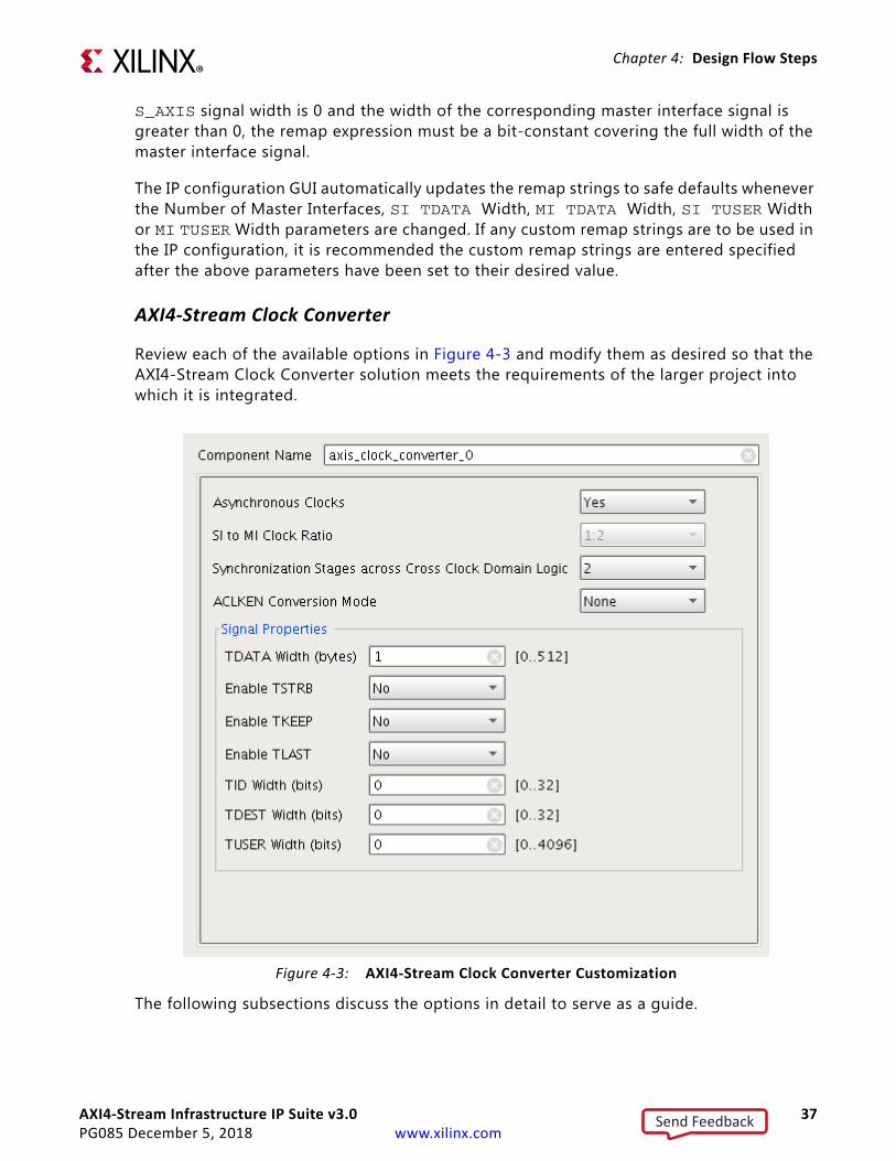
AXI4-Stream Clock Converter
Review each of the available options in Figure 4-3 and modify them as desired so that the AXI4-Stream Clock Converter solution meets the requirements of the larger project into which it is integrated.
The following subsections discuss the options in detail to serve as a guide.
X-Ref Target - Figure 4-3
Figure 4‐3: AXI4-Stream Clock Converter Customization
Send Feedback
AXI4-Stream Infrastructure IP Suite v3.0 38PG085 December 5, 2018 www.xilinx.com
Chapter 4: Design Flow Steps
Global Parameters
When using Vivado IP integrator, the Vivado IDE automatically computes the values of these parameters.
Component Name
The base name of the output files generated for the core. Names must begin with a letter and can be composed of any of the following characters: a to z, 0 to 9, and "_".
Asynchronous Clocks
If set to Yes, then the S_AXIS_ACLK and M_AXIS_ACLK clock signals are assumed to be asynchronous to each other and the IP operates in asynchronous mode. The Slave Interface Clock Frequency Ratio and Master Interface Clock Frequency Ratio options are disabled when the clocks are specified as asynchronous. Asynchronous clock mode should be used unless S_AXIS_ACLK and M_AXIS_ACLK are phase aligned and have frequencies that have either 1:N or N:1 clock frequency ratio.
SI to MI Clock Ratio
This parameter set the ratio in frequency between the S_AXIS_ACLK and the M_AXIS_ACLK inputs if they are not asynchronous.
Synchronization Stages across Cross Clock Domain Logic
When S_AXIS_ACLK and M_AXIS_ACLK are asynchronous to each other, then this parameter specifies the number of synchronization stages to use for cross-clock domain logic. Increasing this value increases the MTBF of design, but incurs increased latency and logic utilization.
ACLKEN Conversion Mode
This pull-down option selects the conversion mode for the ACLKEN signal. Extra latency and logic is incurred when ACLKEN conversion is performed. The options are:
• None - There are no ACLKEN signals associated with the IP.
• S AXIS Only - There is an S_AXIS_ACLKEN signal associated with the S_AXIS_ACLK clock signal and no M_AXIS_ACLKEN signal.
• M AXIS Only - There is an M_AXIS_ACLKEN signal associated with the M_AXIS_ACLK clock signal and no S_AXIS_ACLKEN signal.
• S AXIS and M AXIS - Both clocks have ACLKEN signals associated with them.
Signal Properties
When using Vivado IP integrator, the Vivado IDE automatically computes the values of these parameters.
Send Feedback
AXI4-Stream Infrastructure IP Suite v3.0 39PG085 December 5, 2018 www.xilinx.com
Chapter 4: Design Flow Steps
TDATA Width (bytes)
This parameter specifies the width in bytes of the TDATA signal on all the AXI4-Stream interfaces. This parameter is an integer and can vary from 0 to 512. Set to 0 to omit the TDATA signal. If the TDATA signal is omitted, then the TKEEP and TSTRB signals are also omitted. The width of the port is multiplied by 8 to get the width in bits.
Enable TSTRB
If set to Yes, this parameters specifies if the optional TSTRB signal is present on all the AXI4-Stream interfaces. This option can only be enabled if the TDATA Width (bytes) parameter is greater than 0.
Enable TKEEP
If set to Yes, this parameters specifies if the optional TKEEP signal is present on all the AXI4-Stream interfaces. This option can only be enabled if the TDATA Width (bytes) parameter is greater than 0.
Enable TLAST
If set to Yes, this parameters specifies if the optional TLAST signal is present on all the AXI4-Stream interfaces.
TID Width (bits)
If greater than 0, this parameter specifies if the optional TID signal is present on all the AXI4-Stream interfaces. A value of 0 omits this signal. Values 1 and 32 sets the width of this signal accordingly.
TDEST Width (bits)
If greater than 0, this parameter specifies if the optional TDEST signal is present on all the AXI4-Stream interfaces. A value of 0 omits this signal. Values 1 and 32 sets the width of this signal accordingly.
TUSER Width (bits)
If greater than 0, this parameter specifies if the optional TUSER signal is present on all the AXI4-Stream interfaces. A value of 0 omits this signal. Values 1 and 32 sets the width of this signal accordingly.
Send Feedback
AXI4-Stream Infrastructure IP Suite v3.0 40PG085 December 5, 2018 www.xilinx.com
Chapter 4: Design Flow Steps
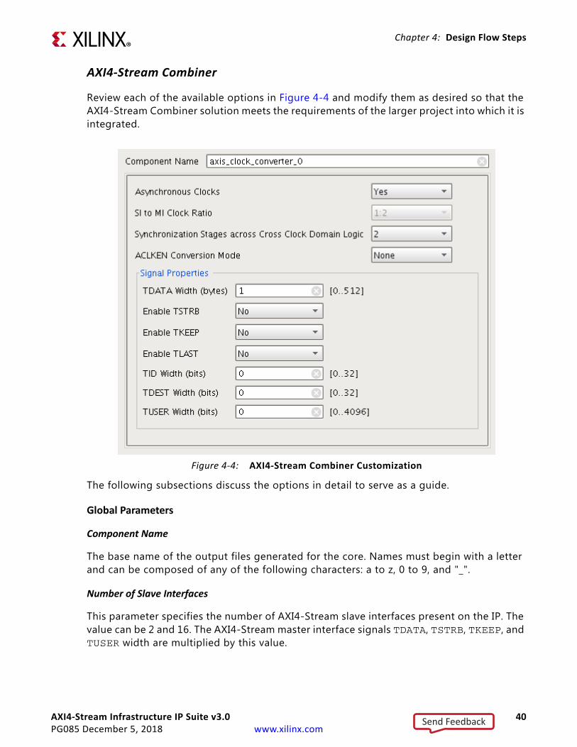
AXI4-Stream Combiner
Review each of the available options in Figure 4-4 and modify them as desired so that the AXI4-Stream Combiner solution meets the requirements of the larger project into which it is integrated.
The following subsections discuss the options in detail to serve as a guide.
Global Parameters
Component Name
The base name of the output files generated for the core. Names must begin with a letter and can be composed of any of the following characters: a to z, 0 to 9, and "_".
Number of Slave Interfaces
This parameter specifies the number of AXI4-Stream slave interfaces present on the IP. The value can be 2 and 16. The AXI4-Stream master interface signals TDATA, TSTRB, TKEEP, and TUSER width are multiplied by this value.
X-Ref Target - Figure 4-4
Figure 4‐4: AXI4-Stream Combiner Customization
Send Feedback
AXI4-Stream Infrastructure IP Suite v3.0 41PG085 December 5, 2018 www.xilinx.com
Chapter 4: Design Flow Steps
Signal Properties
When using Vivado IP integrator, the Vivado IDE automatically computes the values of these parameters.
TDATA Width (bytes)
This parameter specifies the width in bytes of the TDATA signal on each of the AXI4-Stream slave interfaces. The AXI4-Stream master interface TDATA width is this value multiplied by the Number of Slave Interfaces parameter. This parameter is an integer and can vary from 0 to (512/Number of Slave Interfaces). Set to 0 to omit the TDATA signal. If the TDATA signal is omitted, then the TKEEP and TSTRB signals are also omitted. The width of the port is multiplied by 8 to get the width in bits.
Enable TSTRB
If set to Yes, this parameters specifies if the optional TSTRB signal is present on all the AXI4-Stream interfaces. This option can only be enabled if the TDATA Width (bytes) parameter is greater than 0.
Enable TKEEP
If set to Yes, this parameters specifies if the optional TKEEP signal is present on all the AXI4-Stream interfaces. This option can only be enabled if the TDATA Width (bytes) parameter is greater than 0.
Enable TLAST
If set to Yes, this parameters specifies if the optional TLAST signal is present on all the AXI4-Stream interfaces.
TID Width (bits)
If greater than 0, this parameter specifies if the optional TID signal is present on all the AXI4-Stream interfaces. A value of 0 omits this signal. Values 1 and 32 sets the width of this signal accordingly.
TDEST Width (bits)
If greater than 0, this parameter specifies if the optional TDEST signal is present on all the AXI4-Stream interfaces. A value of 0 omits this signal. Values 1 and 32 sets the width of this signal accordingly.
TUSER Width (bits)
If greater than 0, this parameter specifies if the optional TUSER signal is present on all the AXI4-Stream interfaces. A value of 0 omits this signal. Values 1 and 32 sets the width of this signal accordingly on the AXI4-Stream slave interfaces. The AXI4-Stream master interface TUSER width is to set to this value multiplied by Number of Slave Interfaces.
Send Feedback
AXI4-Stream Infrastructure IP Suite v3.0 42PG085 December 5, 2018 www.xilinx.com
Chapter 4: Design Flow Steps
Enable ACLKEN
If set to Yes, this parameter specifies if the optional ACLKEN signal is present with all the AXI4-Stream interfaces clocks.
Primary Slave Interface
This option specifies the Slave Interface that is used to pass the TLAST, TID, and TDEST signals to the master interface.
Enable Command Port Error
If set to Yes, this option enables the s_cmd_err port if TID, TDEST, TLAST signals do not match the slave interface specified by the Primary Slave Interface option.
AXI4-Stream Data FIFO
Review each of the available options in Figure 4-5 and modify them as desired so that the AXI4-Stream Data FIFO solution meets the requirements of the larger project into which it is integrated.
Send Feedback

AXI4-Stream Infrastructure IP Suite v3.0 43PG085 December 5, 2018 www.xilinx.com
Chapter 4: Design Flow Steps
The following subsections discuss the options in detail to serve as a guide.
General Options
Component Name
The base name of the output files generated for the core. Names must begin with a letter and can be composed of any of the following characters: a to z, 0 to 9, and "_".
FIFO depth
This option specifies the depth of the FIFO to be instantiated. FIFO depth can vary between 16 and 32768 (powers of 2 up to 2n for whichever value of n is the current maximum.) Large FIFO depths may not be realizable on certain devices.
X-Ref Target - Figure 4-5
Figure 4‐5: AXI4-Stream Data FIFO Customization
Send Feedback
AXI4-Stream Infrastructure IP Suite v3.0 44PG085 December 5, 2018 www.xilinx.com
Chapter 4: Design Flow Steps
Memory type
Designate the FIFO memory primitive (resource type) to use. Allowable options: Auto - Allow Vivado Synthesis to choose. Distributed RAM - Distributed RAM FIFO (does not support ECC.) Block RAM - Block RAM FIFO. UltraRAM - UltraRAM FIFO (does not support independent clocks.)
Independent clocks
If set to Yes, then the S_AXIS_ACLK and M_AXIS_ACLK clock signals are assumed to be asynchronous to each other and the IP operates in asynchronous mode.
CDC (Clock Domain Crossing) sync stages
When S_AXIS_ACLK and M_AXIS_ACLK are asynchronous to each other, then this parameter specifies the number of synchronization stages to use for cross clock domain logic. Increasing this value increases the MTBF of design, but incurs increased latency and logic utilization.
Enable packet mode
This option enables the Packet Mode option of the FIFO when set to Yes. This option requires the TLAST signal to be enabled. The FIFO operation in Packet Mode is modified to store transfers until the TLAST signal is asserted. When the TLAST signal is asserted or the FIFO is full, the store transfers are presented on the AXI4-Stream master interface.
ACLKEN conversion mode
This pull-down option selects the conversion mode for the ACLKEN signal. Extra latency and logic is incurred when ACLKEN conversion is performed. The options are:
• None - There are no ACLKEN signals associated with the IP.
• S AXIS Only - There is an S_AXIS_ACLKEN signal associated with the S_AXIS_ACLK clock signal and no M_AXIS_ACLKEN signal.
• M AXIS Only - There is an M_AXIS_ACLKEN signal associated with the M_AXIS_ACLK clock signal and no S_AXIS_ACLKEN signal.
• S AXIS & M AXIS - Both clocks have ACLKEN signals associated with them.
Enable ECC
Enables both ECC Encoder and Decoder. ECC enablement only supported on Block RAM and UltraRAM primitive types.
Send Feedback
AXI4-Stream Infrastructure IP Suite v3.0 45PG085 December 5, 2018 www.xilinx.com
Chapter 4: Design Flow Steps
Include ECC error injection
Signal properties
When using Vivado IP integrator, the Vivado IDE automatically computes the values of these parameters.
TDATA width (bytes)
This parameter specifies the width in bytes of the TDATA signal on all the AXI4-Stream interfaces. This parameter is an integer and can vary from 0 to 512. Set to 0 to omit the TDATA signal. If the TDATA signal is omitted, then the TKEEP and TSTRB signals are also omitted. The width of the port is multiplied by 8 to get the width in bits.
Enable TSTRB
If set to Yes, this parameters specifies if the optional TSTRB signal is present on all the AXI4-Stream interfaces. This option can only be enabled if the TDATA Width (bytes) parameter is greater than 0.
Enable TKEEP
If set to Yes, this parameters specifies if the optional TKEEP signal is present on all the AXI4-Stream interfaces. This option can only be enabled if the TDATA Width (bytes) parameter is greater than 0.
Enable TLAST
If set to Yes, this parameters specifies if the optional TLAST signal is present on all the AXI4-Stream interfaces.
TID width (bits)
If greater than 0, this parameter specifies if the optional TID signal is present on all the AXI4-Stream interfaces. A value of 0 omits this signal. Values 1 and 32 sets the width of this signal accordingly.
TDEST width (bits)
If greater than 0, this parameter specifies if the optional TDEST signal is present on all the AXI4-Stream interfaces. A value of 0 omits this signal. Values 1 and 32 sets the width of this signal accordingly.
TUSER Width (bits)
If greater than 0, this parameter specifies if the optional TUSER signal is present on all the AXI4-Stream interfaces. A value of 0 omits this signal. Values 1 and 32 sets the width of this signal accordingly.
Send Feedback
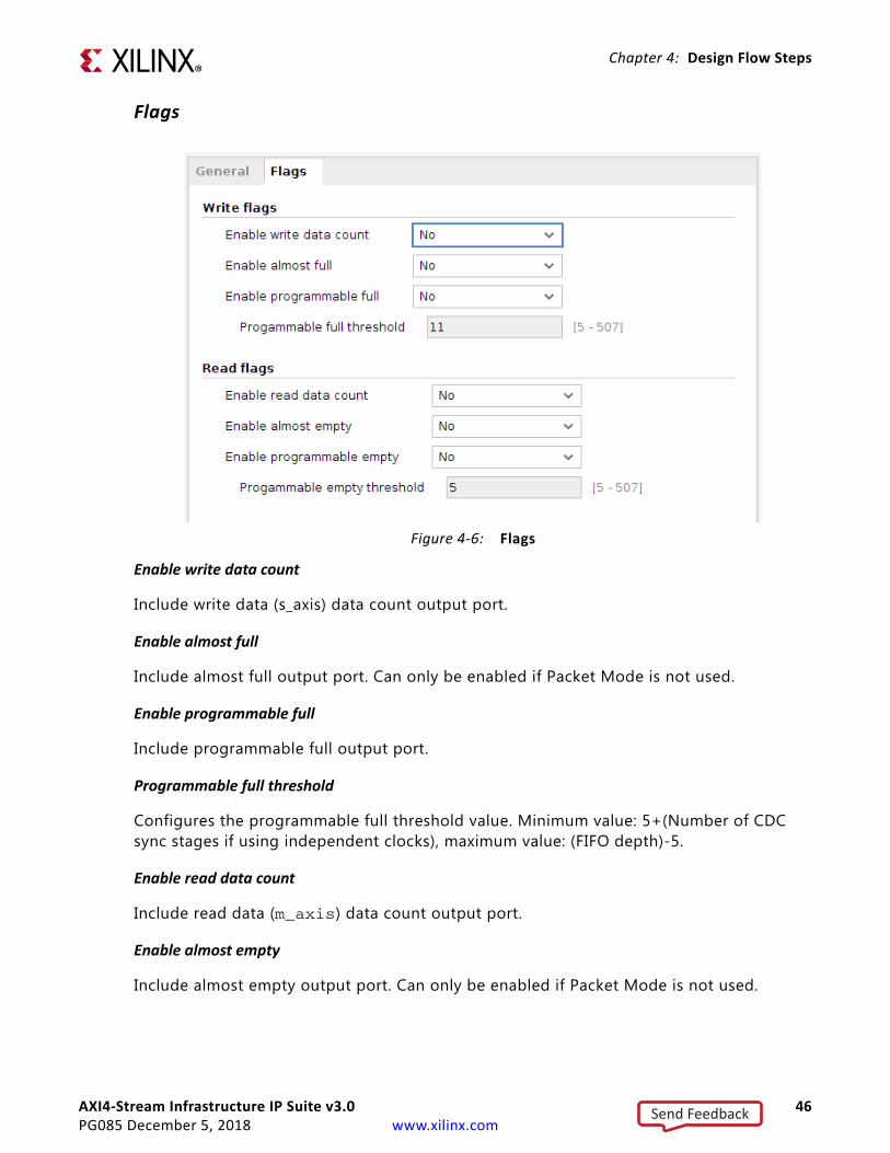
AXI4-Stream Infrastructure IP Suite v3.0 46PG085 December 5, 2018 www.xilinx.com
Chapter 4: Design Flow Steps
Flags
Enable write data count
Include write data (s_axis) data count output port.
Enable almost full
Include almost full output port. Can only be enabled if Packet Mode is not used.
Enable programmable full
Include programmable full output port.
Programmable full threshold
Configures the programmable full threshold value. Minimum value: 5+(Number of CDC sync stages if using independent clocks), maximum value: (FIFO depth)-5.
Enable read data count
Include read data (m_axis) data count output port.
Enable almost empty
Include almost empty output port. Can only be enabled if Packet Mode is not used.
X-Ref Target - Figure 4-6
Figure 4‐6: Flags
Send Feedback
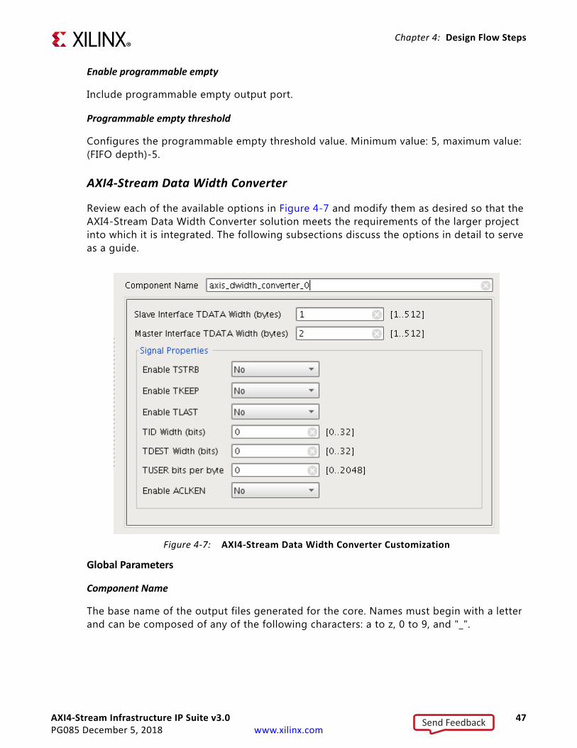
AXI4-Stream Infrastructure IP Suite v3.0 47PG085 December 5, 2018 www.xilinx.com
Chapter 4: Design Flow Steps
Enable programmable empty
Include programmable empty output port.
Programmable empty threshold
Configures the programmable empty threshold value. Minimum value: 5, maximum value: (FIFO depth)-5.
AXI4-Stream Data Width Converter
Review each of the available options in Figure 4-7 and modify them as desired so that the AXI4-Stream Data Width Converter solution meets the requirements of the larger project into which it is integrated. The following subsections discuss the options in detail to serve as a guide.
Global Parameters
Component Name
The base name of the output files generated for the core. Names must begin with a letter and can be composed of any of the following characters: a to z, 0 to 9, and "_".
X-Ref Target - Figure 4-7
Figure 4‐7: AXI4-Stream Data Width Converter Customization
Send Feedback
AXI4-Stream Infrastructure IP Suite v3.0 48PG085 December 5, 2018 www.xilinx.com
Chapter 4: Design Flow Steps
Slave Interface TDATA Width (bytes)
This parameter specifies the width in bytes of the TDATA signal on the AXI4-Stream slave interface. This parameter is an integer and can vary from 1 to 512. The width of the port is multiplied by 8 to get the width in bits. This value cannot be the same as the value of Master Interface TDATA Width (bytes). When using Vivado IP integrator, the Vivado IDE automatically computes the value of this parameter.
Master Interface TDATA Width (bytes)
This parameter specifies the width in bytes of the TDATA signal on the AXI4-Stream master interface. This parameter is an integer and can vary from 1 to 512. The width of the port is multiplied by 8 to get the width in bits. This value cannot be the same as the value of Slave Interface TDATA Width (bytes).
Signal Properties
When using Vivado IP integrator, the Vivado IDE automatically computes the values of these parameters except for Enable Aclken.
Enable TSTRB
If set to Yes, this parameters specifies if the optional TSTRB signal is present on all the AXI4-Stream interfaces.
Enable TKEEP
If set to Yes, this parameters specifies if the optional TKEEP signal is present on all the AXI4-Stream interfaces. Certain configurations may introduce null-bytes into the system. In these situations, the m_axis_tkeep signal is always present regardless of the value of this parameter.
Enable TLAST
If set to Yes, this parameters specifies if the optional TLAST signal is present on all the AXI4-Stream interfaces.
TID Width (bits)
If greater than 0, this parameter specifies if the optional TID signal is present on all the AXI4-Stream interfaces. A value of 0 omits this signal. Values 1 and 32 sets the width of this signal accordingly.
TDEST Width (bits)
If greater than 0, this parameter specifies if the optional TDEST signal is present on all the AXI4-Stream interfaces. A value of 0 omits this signal. Values 1 and 32 sets the width of this signal accordingly.
Send Feedback

AXI4-Stream Infrastructure IP Suite v3.0 49PG085 December 5, 2018 www.xilinx.com
Chapter 4: Design Flow Steps
TUSER Width (bits)
If greater than 0, this parameter specifies if the optional TUSER signal is present on all the AXI4-Stream interfaces. A value of 0 omits this signal. Values 1 and 32 sets the width of this signal accordingly.
Enable ACLKEN
If set to Yes, this parameter specifies if the optional ACLKEN signal is present with all the AXI4-Stream interfaces clocks.
AXI4-Stream Register Slice
Review each of the available options in Figure 4-8 and modify them as desired so that the AXI4-Stream Register Slice solution meets the requirements of the larger project into which it is integrated.
The following subsections discuss the options in detail to serve as a guide.
X-Ref Target - Figure 4-8
Figure 4‐8: AXI4-Stream Register Slice Customization
Send Feedback
AXI4-Stream Infrastructure IP Suite v3.0 50PG085 December 5, 2018 www.xilinx.com
Chapter 4: Design Flow Steps
Signal Properties
When using Vivado IP integrator, the Vivado IDE automatically computes the values of these parameters.
Enable TREADY
If set to Yes, this parameters specifies if the optional TREADY signal is present on all the AXI4-Stream interfaces. Set to No to omit the signal.
TIP: The AXI4-Stream specification recommends that TREADY is always included.
TDATA Width (bytes)
This parameter specifies the width in bytes of the TDATA signal on all the AXI4-Stream interfaces. This parameter is an integer and can vary from 0 to 512. Set to 0 to omit the TDATA signal. If the TDATA signal is omitted, then the TKEEP and TSTRB signals are also omitted. The width of the port is multiplied by 8 to get the width in bits.
Enable TSTRB
If set to Yes, this parameters specifies if the optional TSTRB signal is present on all the AXI4-Stream interfaces. This option can only be enabled if the TDATA Width (bytes) parameter is greater than 0.
Enable TKEEP
If set to Yes, this parameters specifies if the optional TKEEP signal is present on all the AXI4-Stream interfaces. This option can only be enabled if the TDATA Width (bytes) parameter is greater than 0.
Enable TLAST
If set to Yes, this parameters specifies if the optional TLAST signal is present on all the AXI4-Stream interfaces.
TID Width (bits)
If greater than 0, this parameter specifies if the optional TID signal is present on all the AXI4-Stream interfaces. A value of 0 omits this signal. Values 1 and 32 sets the width of this signal accordingly.
TDEST Width (bits)
If greater than 0, this parameter specifies if the optional TDEST signal is present on all the AXI4-Stream interfaces. A value of 0 omits this signal. Values 1 and 32 sets the width of this signal accordingly.
Send Feedback
AXI4-Stream Infrastructure IP Suite v3.0 51PG085 December 5, 2018 www.xilinx.com
Chapter 4: Design Flow Steps
TUSER Width (bits)
If greater than 0, this parameter specifies if the optional TUSER signal is present on all the AXI4-Stream interfaces. A value of 0 omits this signal. Values 1 and 32 sets the width of this signal accordingly.
Enable ACLKEN
If set to Yes, this parameter specifies if the optional ACLKEN signal is present with all the AXI4-Stream interfaces clocks.
Advanced Properties
Register Pipeline Type
This property allows for the trade-off between performance and area efficiency.
Default: A two-deep registered mode (supports back-to-back transfers) that balances performance with low input fanout, as used in the AXI4-Stream Switch.
Fully-registered: Similar to Default (supports back-to-back transfers), except all payload and handshake outputs are driven directly from registers.
Light-weight: Inserts one bubble cycle after each transfer.
SLR Crossing: Adds extra pipeline stages to optimally cross one super logic region (SLR) boundary in stacked silicon interconnect (SSI) devices. All SLR crossings are flop-to-flop with fanout=1. See Floor Planning Constraints for AXI4-Stream Register Slice SLR Crossing Modes for floorplanning guidance.
SLR TDM Crossing: Similar to SLR Crossing, except it consumes half number of payload wires across the SLR boundary and propagates the cross-SLR signals at twice the frequency of the AXI interfaces.
Bypass: Directly connects the slave interface to the master interface.
Bypass-Endpoint: Similar to Bypass, except for allowing interface properties to be treated as fixed values during IP integrator design validation.
Multi SLR Crossing: Supports spanning zero or more SLR boundaries using a single Register Slice instance. Also inserts additional pipeline stages within each SLR to help meet timing goals.
Number of SLR Crossings: When using Multi SLR Crossing mode, select the number of SLR boundaries to be crossed within the core.
Pipeline Stages within Master-side SLR: When using Multi SLR Crossing mode, select the number of additional pipeline stages to insert within the master-side SLR (between the SLR boundary and the SI interface).
Send Feedback
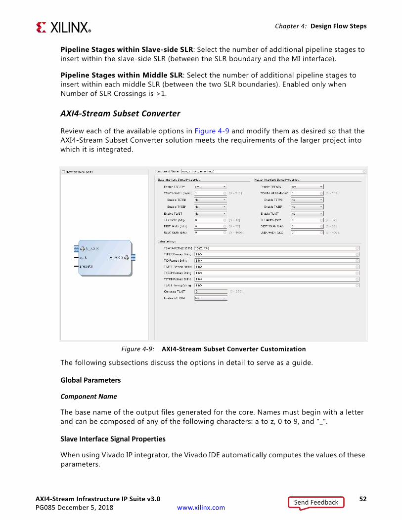
AXI4-Stream Infrastructure IP Suite v3.0 52PG085 December 5, 2018 www.xilinx.com
Chapter 4: Design Flow Steps
Pipeline Stages within Slave-side SLR: Select the number of additional pipeline stages to insert within the slave-side SLR (between the SLR boundary and the MI interface).
Pipeline Stages within Middle SLR: Select the number of additional pipeline stages to insert within each middle SLR (between the two SLR boundaries). Enabled only when Number of SLR Crossings is >1.
AXI4-Stream Subset Converter
Review each of the available options in Figure 4-9 and modify them as desired so that the AXI4-Stream Subset Converter solution meets the requirements of the larger project into which it is integrated.
The following subsections discuss the options in detail to serve as a guide.
Global Parameters
Component Name
The base name of the output files generated for the core. Names must begin with a letter and can be composed of any of the following characters: a to z, 0 to 9, and "_".
Slave Interface Signal Properties
When using Vivado IP integrator, the Vivado IDE automatically computes the values of these parameters.
X-Ref Target - Figure 4-9
Figure 4‐9: AXI4-Stream Subset Converter Customization
Send Feedback
AXI4-Stream Infrastructure IP Suite v3.0 53PG085 December 5, 2018 www.xilinx.com
Chapter 4: Design Flow Steps
Enable TREADY
If set to Yes, this parameters specifies if the optional TREADY signal is present on the AXI4-Stream slave interface. Set to No to omit the signal.
TIP: The AXI4-Stream specification recommends that TREADY is always included.
TDATA Width (bytes)
This parameter specifies the width in bytes of the TDATA signal on the AXI4-Stream slave interface. This parameter is an integer and can vary from 0 to 512. Set to 0 to omit the TDATA signal. If the TDATA signal is omitted, then the TKEEP and TSTRB signals are also omitted. The width of the port is multiplied by 8 to get the width in bits.
Enable TSTRB
If set to Yes, this parameters specifies if the optional TSTRB signal is present on the AXI4-Stream slave interface. This option can only be enabled if the TDATA Width (bytes) parameter is greater than 0.
Enable TKEEP
If set to Yes, this parameters specifies if the optional TKEEP signal is present on the AXI4-Stream slave interface. This option can only be enabled if the TDATA Width (bytes) parameter is greater than 0.
Enable TLAST
If set to Yes, this parameters specifies if the optional TLAST signal is present on the AXI4-Stream slave interface.
TID Width (bits)
If greater than 0, this parameter specifies if the optional TID signal is present on the AXI4-Stream slave interface. A value of 0 omits this signal. Values 1 and 32 sets the width of this signal accordingly.
TDEST Width (bits)
If greater than 0, this parameter specifies if the optional TDEST signal is present on the AXI4-Stream slave interface. A value of 0 omits this signal. Values 1 and 32 sets the width of this signal accordingly.
TUSER Width (bits)
If greater than 0, this parameter specifies if the optional TUSER signal is present on the AXI4-Stream slave interface. A value of 0 omits this signal. Values 1 and 32 sets the width of this signal accordingly.
Send Feedback
AXI4-Stream Infrastructure IP Suite v3.0 54PG085 December 5, 2018 www.xilinx.com
Chapter 4: Design Flow Steps
Master Interface Signal Properties
When using Vivado IP integrator, the Vivado IDE automatically computes the values of these parameters.
Enable TREADY
If set to Yes, this parameters specifies if the optional TREADY signal is present on the AXI4-Stream slave interface. Set to No to omit the signal.
TIP: The AXI4-Stream specification recommends that TREADY is always included.
TDATA Width (bytes)
This parameter specifies the width in bytes of the TDATA signal on the AXI4-Stream slave interface. This parameter is an integer and can vary from 0 to 512. Set to 0 to omit the TDATA signal. If the TDATA signal is omitted, then the TKEEP and TSTRB signals are also omitted. The width of the port is multiplied by 8 to get the width in bits.
Enable TSTRB
If set to Yes, this parameters specifies if the optional TSTRB signal is present on the AXI4-Stream slave interface. This option can only be enabled if the TDATA Width (bytes) parameter is greater than 0.
Enable TKEEP
If set to Yes, this parameters specifies if the optional TKEEP signal is present on the AXI4-Stream slave interface. This option can only be enabled if the TDATA Width (bytes) parameter is greater than 0.
Enable TLAST
If set to Yes, this parameters specifies if the optional TLAST signal is present on the AXI4-Stream slave interface.
TID Width (bits)
If greater than 0, this parameter specifies if the optional TID signal is present on the AXI4-Stream slave interface. A value of 0 omits this signal. Values 1 and 32 sets the width of this signal accordingly.
TDEST Width (bits)
If greater than 0, this parameter specifies if the optional TDEST signal is present on the AXI4-Stream slave interface. A value of 0 omits this signal. Values 1 and 32 sets the width of this signal accordingly.
Send Feedback

AXI4-Stream Infrastructure IP Suite v3.0 55PG085 December 5, 2018 www.xilinx.com
Chapter 4: Design Flow Steps
TUSER Width (bits)
If greater than 0, this parameter specifies if the optional TUSER signal is present on the AXI4-Stream slave interface. A value of 0 omits this signal. Values 1 and 32 sets the width of this signal accordingly.
Extra Settings
TDATA/TUSER/TID/TDEST/TSTRB/TKEEP/TLAST Remap String
The remap string parameters are used to remap input to output bytes/bits of the TDATA/TUSER/TID/TDES/TSTRB/TKEEP/TLAST signals, respectively.
The format of the remap user parameter follows syntax similar to Verilog vector concatenation.
• The remap parameter is a comma separated list of elements.
• Each element is either a constant or a bit slice of one or more SI signals.
° For example, if SI and MI TDATA width have the same value 32, the remap string tdata[31:0] passes the entire TDATA signal from SI to MI unmodified.
° If the MI TDATA signal were 24 bits and the SI TDATA signal were 16 bits, a remap string of 8b00000000,tdata[15:0] assigns a constant 0 to the upper 8 bits of the MI signal and pass the SI TDATA through on the lower 16 bits.
• A bit-slice element can reference a single bit of an SI signal (e.g., TDATA[0]) or a vector slice of an SI signal (e.g., tdata[11:8]).
° The index values must not exceed the indices of the SI signal.
• The same SI bit can be mapped multiple times into the MI output.
° For example, tdata[7:0], tdata[7:0] repeats the SI TDATA least significant byte twice on MI signal.
• The combined width of the constants and the SI bit slices in the remap parameter must match the MI signal width.
• The right-most element defines the least significant bits of the MI signal and the left-most element defines the most significant bits of the MI signal.
• The remap string can reference bits of the corresponding SI signal or bits from another remappable SI signal.
° For example, the remap string for TDATA may reference bits from the TUSER SI signal.
• Constant elements and bit-slice elements can be freely mixed in the comma separated list of elements.
° For example, tdata[7:0],8b00000000,tdata[15:8] is a valid expression.
Send Feedback
AXI4-Stream Infrastructure IP Suite v3.0 56PG085 December 5, 2018 www.xilinx.com
Chapter 4: Design Flow Steps
• Only binary format constant elements are supported.
° h format is not supported.
• The constant element must specify the number of bits that follow b and the number of bits that follow b must match the number of bits specified. If not, a validation error is given.
• If the SI signal width is 0, the remap string must be a constant element.
• If the MI signal width is 0, the remap string is 1b0.
• Bit slices are only valid when the SI signal width is greater than 0.
• When using IP inside of Vivado IP integrator, both m_axis and s_axis port widths of the remapped value should be set to manual override if write_bd_tcl is used.
Generate TLAST
This parameter can be set if the TLAST signal is enabled on the master interface, but not on the slave interface. The number specifies how many transfers to count before asserting the TLAST signal. A value of 0 indicates that the TLAST signal should always be de-asserted. Conversely, a value of 1 indicates that the TLAST signal should be asserted on every transfer. A value of 2 indicates that the TLAST signal should be asserted on every other transfer and so on. Values 0 and 256 are accepted.
Enable ACLKEN
If set to Yes, this parameter specifies if the optional ACLKEN signal is present with all the AXI4-Stream interfaces clocks.
AXI4-Stream Switch
Review each of the available options in Figure 4-10 and modify them as desired so that the AXI4-Stream Switch solution meets the requirements of the larger project into which it is integrated.
Send Feedback
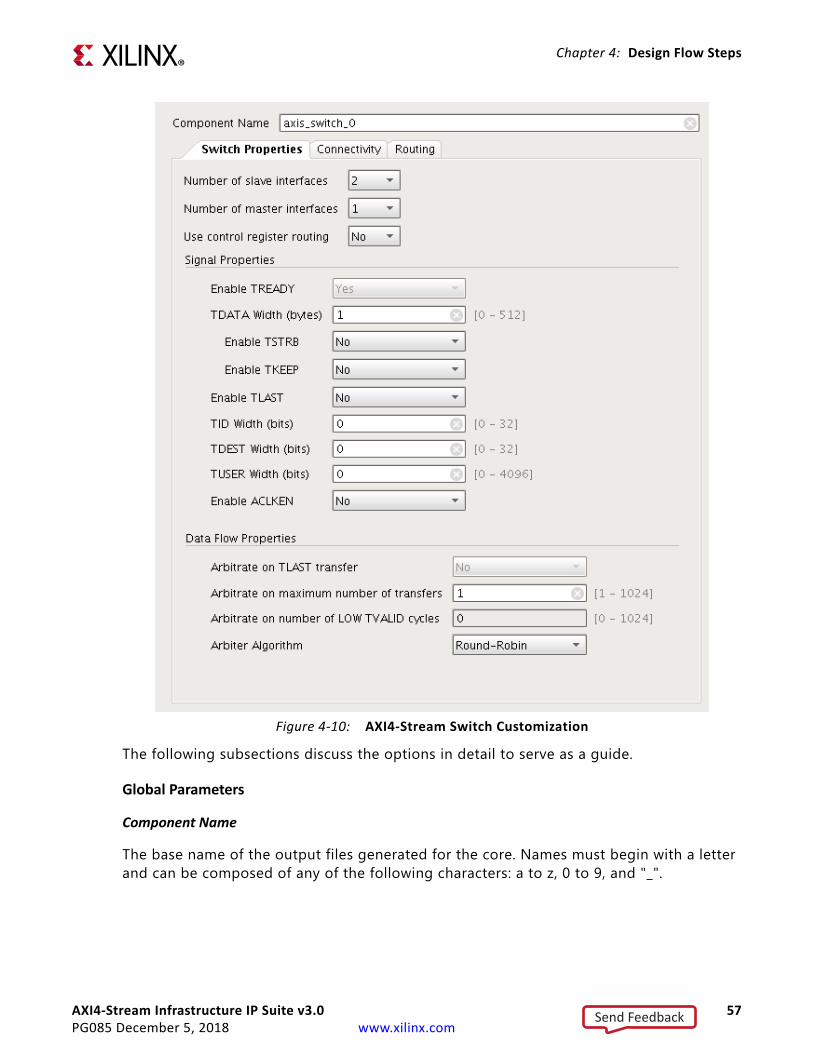
AXI4-Stream Infrastructure IP Suite v3.0 57PG085 December 5, 2018 www.xilinx.com
Chapter 4: Design Flow Steps
The following subsections discuss the options in detail to serve as a guide.
Global Parameters
Component Name
The base name of the output files generated for the core. Names must begin with a letter and can be composed of any of the following characters: a to z, 0 to 9, and "_".
X-Ref Target - Figure 4-10
Figure 4‐10: AXI4-Stream Switch Customization
Send Feedback
AXI4-Stream Infrastructure IP Suite v3.0 58PG085 December 5, 2018 www.xilinx.com
Chapter 4: Design Flow Steps
Switch Properties
Number of Slave Interfaces
This parameter specifies the number of AXI4-Stream slave interfaces present on the IP. The value can be 1 and 16. This value cannot be set to 1 when Number of Master Interfaces is 1.
Number of Master Interfaces
This parameter specifies the number of AXI4-Stream master interfaces present on the IP. The value can be 1 and 16. This value cannot be set to 1 when Number of Slave Interfaces is 1.
Use Control Register Routing
This parameter specifies the routing mode. Control register routing enables the AXI4-Lite control register interface to handle transfer routing. If this option is set to No, then the inline TDEST value is used for routing. Enabling this option disables the Routing tab.
Signal Properties
When using Vivado IP integrator, the Vivado IDE automatically computes the values of these parameters.
TDATA Width (bytes)
This parameter specifies the width in bytes of the TDATA signal on all the AXI4-Stream interfaces. This parameter is an integer and can vary from 0 to 512. Set to 0 to omit the TDATA signal. If the TDATA signal is omitted, then the TKEEP and TSTRB signals are also omitted. The width of the port is multiplied by 8 to get the width in bits.
Enable TSTRB
If set to Yes, this parameters specifies if the optional TSTRB signal is present on all the AXI4-Stream interfaces. This option can only be enabled if the TDATA Width (bytes) parameter is greater than 0.
Enable TKEEP
If set to Yes, this parameters specifies if the optional TKEEP signal is present on all the AXI4-Stream interfaces. This option can only be enabled if the TDATA Width (bytes) parameter is greater than 0.
Enable TLAST
If set to Yes, this parameters specifies if the optional TLAST signal is present on all the AXI4-Stream interfaces.
Send Feedback
AXI4-Stream Infrastructure IP Suite v3.0 59PG085 December 5, 2018 www.xilinx.com
Chapter 4: Design Flow Steps
TID Width (bits)
If greater than 0, this parameter specifies if the optional TID signal is present on all the AXI4-Stream interfaces. A value of 0 omits this signal. Values 1 and 32 sets the width of this signal accordingly.
TDEST Width (bits)
If greater than 0, this parameter specifies if the optional TDEST signal is present on all the AXI4-Stream interfaces. A value of 0 omits this signal. Values 1 and 32 sets the width of this signal accordingly.
TUSER Width (bits)
If greater than 0, this parameter specifies if the optional TUSER signal is present on all the AXI4-Stream interfaces. A value of 0 omits this signal. Values 1 and 32 sets the width of this signal accordingly.
Enable ACLKEN
If set to Yes, this parameter specifies if the optional ACLKEN signal is present with all the AXI4-Stream interfaces clocks.
Data Flow Properties
Data Flow Properties options are available to modify only if the Number of Slave Interfaces is greater than 1 and Use control register routing is set to No.
Arbitrate on Maximum Number of Transfers
This setting specifies how many transfers to count before relinquishing the granted arbitration. If set to zero, then the number is infinite and Arbitrate on TLAST transfer must be set. If set to one, then after each transfer, the interconnect switch relinquishes control and requests another arbitration. If set to a value greater than one, then after the specified number of transfers, the arbitration is relinquished. For example, setting this value to 16 allows 16 transfers to pass from slave interface to master interface per each arbitration grant.
Arbitrate on Number of LOW TVALID Cycles
This setting allows relinquishing of a granted arbitration without a transfer. A watchdog timer is instantiated and counts the number of consecutive LOW TVALID signals the granted SI and MI interfaces. When the requisite number of LOW TVALID cycles is counted as specified here, the switch relinquishes the granted arbitration and signals that the transaction is complete to the arbiter. If this setting is set to 0, no watchdog timer is instantiated. If there is more than one slave interface, more than one master interface, and the Arbitrate on maximum number of transfers setting is greater than 1, this setting cannot be set to zero. This ensures that deadlock cannot occur.
Send Feedback
AXI4-Stream Infrastructure IP Suite v3.0 60PG085 December 5, 2018 www.xilinx.com
Chapter 4: Design Flow Steps
Arbitrate on TLAST Transfer
If checked, this setting indicates that a transaction is complete when a transfer with TLAST asserted passes from the slave interface to the master interface of the interconnect switch. The arbiter is then able to arbitrate to the next arbitration winner.
Arbiter Algorithm
There are three arbitration algorithms available to choose from. The True Round-Robin algorithm arbitrates between all the slave interfaces in a round robin fashion. If all slave interfaces are not active, then it adapts to provide an equal weighting for each active slave interface. The ordering starts with S00, then S01, down to S15. The slave interface following the one that was last granted has the highest priority next. The Round-Robin algorithm operates similarly to the True Round-Robin option except that after a successful grant, it proceeds to the next arbitration order regardless of which slave interface was granted. Fixed-Priority algorithm issues the highest priority to S00, and the lowest priority to S15 for every arbitration cycle. System-level traffic profiles for Fixed-Priority algorithm must be carefully understood to avoid starvation of lower-priority ports.
Consider the scenario where there is a 4 SI to 1 MI switch with ports S00, S02, and S03 continuously requesting transfers with large transactions. After a large number of arbitrations, the algorithms produces different utilizations. The True Round-Robin provides 33% of the available bandwidth to each of the ports S00, S02, and S03. The Round-Robin algorithm provides 25% of the available bandwidth to ports S00 and S03, and 50% to port S02. This is because port S02 gains ports S01 bandwidth. The Fixed-Priority algorithm provides 100% bandwidth to port S00, and starve the other 2 requesting ports.
Regardless of arbiter algorithm, the arbiter does not support back-to-back transfers from the same slave interface. This configuration has two implications. If only one interface is requesting to a particular master, then only 50% of the bandwidth will be realized. If using the fixed-priority arbitration in the scenario described previously, then the ports S00 and S02 would get 50% bandwidth allocation.
Pipeline Registers
Pipeline register options are available to set when using the Use control register routing is set to Yes.
Enable Input Pipeline Register
When enabled, the slave interface side of the switch has register slices for each port at the IP boundary.
Enable Output Pipeline Register
When enabled, the master interface side of the switch has register slices for each port at the IP boundary.
Send Feedback
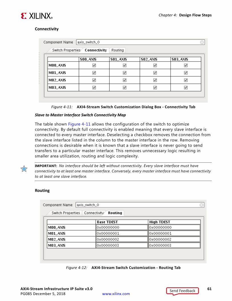
AXI4-Stream Infrastructure IP Suite v3.0 61PG085 December 5, 2018 www.xilinx.com
Chapter 4: Design Flow Steps
Connectivity
Slave to Master Interface Switch Connectivity Map
The table shown Figure 4-11 allows the configuration of the switch to optimize connectivity. By default full connectivity is enabled meaning that every slave interface is connected to every master interface. Deselecting a checkbox removes the connection from the slave interface listed in the column to the master interface in the row. Removing connections is desirable when it is known that a slave interface is never going to send transfers to a particular master interface. This removes unnecessary logic resulting in smaller area utilization, routing and logic complexity.
IMPORTANT: No interface should be left without connectivity. Every slave interface must have connectivity to at least one master interface. Conversely, every master interface must have connectivity to at least one slave interface.
Routing
X-Ref Target - Figure 4-11
Figure 4‐11: AXI4-Stream Switch Customization Dialog Box - Connectivity Tab
X-Ref Target - Figure 4-12
Figure 4‐12: AXI4-Stream Switch Customization - Routing Tab
Send Feedback
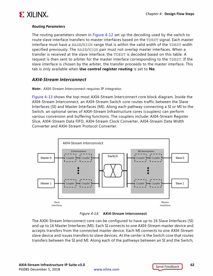
AXI4-Stream Infrastructure IP Suite v3.0 62PG085 December 5, 2018 www.xilinx.com
Chapter 4: Design Flow Steps
Routing Parameters
The routing parameters shown in Figure 4-12 set up the decoding used by the switch to route slave interface transfers to master interfaces based on the TDEST signal. Each master interface must have a BASE/HIGH range that is within the valid width of the TDEST width specified previously. The BASE/HIGH pair must not overlap master interfaces. When a transfer is received at the slave interface, the TDEST is decoded based on this table. A request is then sent to arbiter for the master interface corresponding to the TDEST. If the slave interface is chosen by the arbiter, the transfer proceeds to the master interface. This tab is only available when Use control register routing is set to No.
AXI4-Stream Interconnect
Note: AXI4-Stream Interconnect requires IP integrator.
Figure 4-13 shows the top-most AXI4-Stream Interconnect core block diagram. Inside the AXI4-Stream Interconnect, an AXI4-Stream Switch core routes traffic between the Slave Interfaces (SI) and Master Interfaces (MI). Along each pathway connecting a SI or MI to the Switch, an optional series of AXI4-Stream Infrastructure cores (couplers) can perform various conversion and buffering functions. The couplers include: AXI4-Stream Register Slice, AXI4-Stream Data FIFO, AXI4-Stream Clock Converter, AXI4-Stream Data Width Converter and AXI4-Stream Protocol Converter.
The AXI4-Stream Interconnect core can be configured to have up to 16 Slave Interfaces (SI) and up to 16 Master Interfaces (MI). Each SI connects to one AXI4-Stream master device and accepts transfers from the connected master device. Each MI connects to one AXI4-Stream slave device and issues transfers to slave devices. At the center is the Switch core that routes transfers between the SI and MI. Along each of the pathways between an SI and the Switch,
X-Ref Target - Figure 4-13
Figure 4‐13: AXI4-Stream Interconnect
Send Feedback
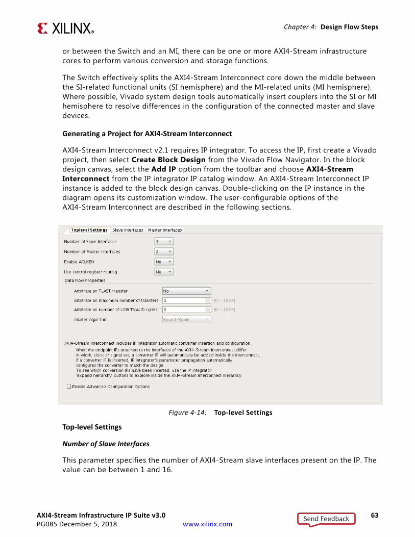
AXI4-Stream Infrastructure IP Suite v3.0 63PG085 December 5, 2018 www.xilinx.com
Chapter 4: Design Flow Steps
or between the Switch and an MI, there can be one or more AXI4-Stream infrastructure cores to perform various conversion and storage functions.
The Switch effectively splits the AXI4-Stream Interconnect core down the middle between the SI-related functional units (SI hemisphere) and the MI-related units (MI hemisphere). Where possible, Vivado system design tools automatically insert couplers into the SI or MI hemisphere to resolve differences in the configuration of the connected master and slave devices.
Generating a Project for AXI4-Stream Interconnect
AXI4-Stream Interconnect v2.1 requires IP integrator. To access the IP, first create a Vivado project, then select Create Block Design from the Vivado Flow Navigator. In the block design canvas, select the Add IP option from the toolbar and choose AXI4-Stream Interconnect from the IP integrator IP catalog window. An AXI4-Stream Interconnect IP instance is added to the block design canvas. Double-clicking on the IP instance in the diagram opens its customization window. The user-configurable options of the AXI4-Stream Interconnect are described in the following sections.
Top-level Settings
Number of Slave Interfaces
This parameter specifies the number of AXI4-Stream slave interfaces present on the IP. The value can be between 1 and 16.
X-Ref Target - Figure 4-14
Figure 4‐14: Top-level Settings
Send Feedback

AXI4-Stream Infrastructure IP Suite v3.0 64PG085 December 5, 2018 www.xilinx.com
Chapter 4: Design Flow Steps
Number of Master Interfaces
This parameter specifies the number of AXI4-Stream master interfaces present on the IP. The value can be between 1 and 16.
Enable ACLKEN
If set to Yes, this parameter specifies if the optional ACLKEN signal is present with all the AXI4-Stream interfaces clocks.
Use Control Register Routing
This parameter specifies the routing mode. Control register routing enables the AXI4-Lite control register interface to handle transfer routing. If this option is set to No, then the inline TDEST value is used for routing.
Data Flow Properties
Data Flow Properties options are available to modify only if the Number of Slave Interfaces is greater than 1.
Arbitrate on Maximum Number of Transfers
This setting specifies how many transfers to count before relinquishing the granted arbitration and is passed directly to the AXI4-Stream Switch within the AXI4-Stream Interconnect instance. Consult the AXI4-Stream Switch parameter descriptions for more details on the valid value range and use of this parameter.
Arbitrate on Number of LOW TVALID Cycles
This setting allows relinquishing of a granted arbitration without a transfer and is passed directly to the AXI4-Stream Switch within the AXI4-Stream Interconnect instance. Consult the AXI4-Stream Switch parameter descriptions for more details on the valid value range and use of this parameter.
Arbitrate on TLAST Transfer
This setting allows relinquishing of a granted arbitration when a transfer with TLAST asserted is received and is passed directly to the AXI4-Stream Switch within the AXI4-Stream Interconnect instance. Consult the AXI4-Stream Switch parameter descriptions for more details on the valid value range and use of this parameter.
Arbiter Algorithm
This setting allows the selection of an arbitration algorithm and is passed directly to the AXI4_Stream Switch within the AXI4-Stream Interconnect instance. Consult the AXI4-Stream Switch parameter descriptions for more details on the valid value range and use of this parameter.
Send Feedback

AXI4-Stream Infrastructure IP Suite v3.0 65PG085 December 5, 2018 www.xilinx.com
Chapter 4: Design Flow Steps
Enable Register Slice
If checked, an AXI4-Stream Register slice is inserted in the SI hemisphere couplers between the Snn_AXIS interface and the AXI4-Stream Switch.
FIFO Depth
If a value greater than 0 is selected, an AXI4-Stream Data FIFO is inserted in the SI hemisphere couplers between the Snn_AXIS interface and the AXI4-Stream Switch. The selected depth of the FIFO is configured directly into the AXI4-Stream Data FIFO instance.
FIFO Packet Mode
If checked and if a FIFO depth greater than 0 is selected for Snn_AXIS, the AXI4-Stream Data FIFO's packet mode is enabled. Consult the AXI4-Data FIFO parameter descriptions for more details on packet mode operation.
X-Ref Target - Figure 4-15
Figure 4‐15: Slave Interfaces
Send Feedback

AXI4-Stream Infrastructure IP Suite v3.0 66PG085 December 5, 2018 www.xilinx.com
Chapter 4: Design Flow Steps
Enable Register Slice
If checked, an AXI4-Stream Register slice is inserted in the MI hemisphere couplers between the AXI4-Stream Switch and Mnn_AXIS interface.
FIFO Depth
If a value greater than 0 is selected, an AXI4-Stream Data FIFO is inserted in the MI hemisphere couplers between the AXI4-Stream Switch and the Mnn_AXIS interface. The selected depth of the FIFO is configured directly into the AXI4-Stream Data FIFO instance. Consult the AXI4-Stream Data FIFO parameter descriptions for more details on the valid range of FIFO depth.
FIFO Packet Mode
If checked and if a FIFO depth greater than 0 is selected for Snn_AXIS, the AXI4-Stream Data FIFO's packet mode is enabled. Consult the AXI4-Stream Data FIFO parameter descriptions for more details on packet mode operation.
Base TDEST and High TDEST
The routing parameters shown in Figure 4-16 set up the decoding to route slave interface transfers to master interfaces based on the TDEST signal and are passed directly to the AXI4-Stream Switch instance within the AXI4-Stream Interconnect. Consult the AXI4-Stream Switch parameter descriptions for more details on the valid range and use of routing
X-Ref Target - Figure 4-16
Figure 4‐16: Master Interfaces
Send Feedback
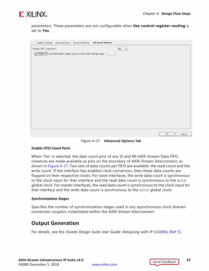
AXI4-Stream Infrastructure IP Suite v3.0 67PG085 December 5, 2018 www.xilinx.com
Chapter 4: Design Flow Steps
parameters. These parameters are not configurable when Use control register routing is set to Yes.
Enable FIFO Count Ports
When 'Yes' is selected, the data count pins of any SI and MI AXI4-Stream Data FIFO instances are made available as pins on the boundary of AXI4-Stream Interconnect, as shown in Figure 4-17. Two sets of data counts per FIFO are available: the read count and the write count. If the interface has enabled clock conversion, then these data counts are flopped on their respective clocks. For slave interfaces, the write data count is synchronous to the clock input for that interface and the read data count is synchronous to the ACLK global clock. For master interfaces, the read data count is synchronous to the clock input for that interface and the write data count is synchronous to the ACLK global clock.
Synchronization Stages
Specifies the number of synchronization stages used in any asynchronous clock domain conversion couplers instantiated within the AXI4-Stream Interconnect.
Output Generation
For details, see the Vivado Design Suite User Guide: Designing with IP (UG896) [Ref 5].
X-Ref Target - Figure 4-17
Figure 4‐17: Advanced Options Tab
Send Feedback
AXI4-Stream Infrastructure IP Suite v3.0 68PG085 December 5, 2018 www.xilinx.com
Chapter 4: Design Flow Steps
Constraining the CoreThis section contains information about constraining the core in the Vivado Design Suite.
Required Constraints
The AXI4-Stream Infrastructure IP does not generally require any additional timing constraints other than clock period constraints on its clocks inputs. When an asynchronous clock converter is utilized, the underlying Xilinx Parameterized Macro is instantiated and generates an internal constraint file to prevent timing paths crossing clock domains from causing false timing errors. Those constraints apply only to internal logic inside the AXI4-Stream Infrastructure IP and are automatically generated with the IP.
Floor Planning Constraints for AXI4-Stream Register Slice SLR Crossing Modes
When using the AXI4-Stream Register Slice core in either the SLR Crossing, SLR TDM Crossing, or Multi SLR Crossing modes, the constraints can be applied to explicitly floor plan the submodules of the core into adjacent SLRs. This ensures that the SLR crossing occurs between the intended flop-to-flop, unit-fanout, internal wires across all payload and handshake pathways within the core.
SLR Crossing and SLR TDM Crossing Modes
After synthesis, all logic and registers placed into the "source" SLR (where the AXI4-Stream master connected to the SI interface is located) contain the cell name pattern "*slr_source*". All logic and registers placed into the "destination" SLR (where the AXI4-Stream slave connected to the MI interface is located) contain the cell name pattern "*slr_dest*". Constraints that combine the instance name of the AXI4-Stream Register Slice and either of these sub-module name patterns can then be used to group all cells in the core into their respective PBLOCKs for floorplanning.
In the following example, an AXI4-Stream Register Slice instance named "my_reg" is constrained to cross a SLR boundary that exists in the target device between row Y4 (the top of the lower SLR) and row Y5 (the bottom of the upper SLR):
create_pblock master_slradd_cells_to_pblock [get_pblocks master_slr] [get_cells -hierarchical -filter "NAME=~*my_reg*slr_source*"]resize_pblock [get_pblocks master_slr] -add {CLOCKREGION_X0Y0:CLOCKREGION_X5Y4}create_pblock slave_slradd_cells_to_pblock [get_pblocks slave_slr] [get_cells -hierarchical -filter "NAME=~*my_reg*slr_dest*"]resize_pblock [get_pblocks slave_slr] -add {CLOCKREGION_X0Y5:CLOCKREGION_X5Y9}
Send Feedback

AXI4-Stream Infrastructure IP Suite v3.0 69PG085 December 5, 2018 www.xilinx.com
Chapter 4: Design Flow Steps
Multi SLR Crossing Mode
After synthesis, all logic and registers that should be placed into the master-side SLR (where the AXI4-Stream master connected to the SI interface is located) contain the cell name pattern *slr_master*. All logic and registers that should be placed into the slave-side SLR (where the AXI4-Stream slave connected to the MI interface is located) contain the cell name pattern *slr_slave*. When spanning three SLRs, all logic and registers that should be placed into the middle SLR contain the cell name pattern *slr_middle*. When spanning four SLRs, all logic and registers that should be placed into the middle SLR adjacent to the master contain the cell name pattern *slr_middle_master*, and all logic and registers that should be placed into the middle SLR adjacent to the slave contain the cell name pattern *slr_middle_slave*.
Constraints that combine the instance name of the Register Slice and any of these submodule name patterns can then be used to group all cells in the core into their respective PBLOCKs for floorplanning.
In the following example, an AXI4-Stream Register Slice instance named my_reg is configured in MultiSLR Crossing mode to cross two SLR boundaries that exist in the target device.
One of the boundaries exists between row Y4 (the top of the lower SLR) and row Y5 (the bottom of the middle SLR). The other boundary exists between row Y9 (the top of the middle SLR) and row Y10 (the bottom of the upper SLR).
create_pblock lower_slradd_cells_to_pblock [get_pblocks lower_slr] [get_cells -hierarchical -filter"NAME=~*my_reg*slr_master*"]resize_pblock [get_pblocks lower_slr] -add {CLOCKREGION_X0Y0:CLOCKREGION_X5Y4}create_pblock center_slradd_cells_to_pblock [get_pblocks center_slr] [get_cells -hierarchical -filter"NAME=~*my_reg*slr_middle*"]resize_pblock [get_pblocks center_slr] -add {CLOCKREGION_X0Y5:CLOCKREGION_X5Y9}create_pblock upper_slradd_cells_to_pblock [get_pblocks upper_slr] [get_cells -hierarchical -filter"NAME=~*my_reg*slr_slave*"]resize_pblock [get_pblocks upper_slr] -add {CLOCKREGION_X0Y10:CLOCKREGION_X5Y14}
Device, Package, and Speed Grade Selections
This section is not applicable for this IP core.
Clock Frequencies
This section is not applicable for this IP core.
Clock Management
This section is not applicable for this IP core.
Send Feedback
AXI4-Stream Infrastructure IP Suite v3.0 70PG085 December 5, 2018 www.xilinx.com
Chapter 4: Design Flow Steps
Clock Placement
This section is not applicable for this IP core.
Banking
This section is not applicable for this IP core.
Transceiver Placement
This section is not applicable for this IP core.
I/O Standard and Placement
This section is not applicable for this IP core.
SimulationFor comprehensive information about Vivado simulation components, as well as information about using supported third party tools, see the Vivado Design Suite User Guide: Logic Simulation (UG900) [Ref 8].
Synthesis and ImplementationFor details about synthesis and implementation, see the Vivado Design Suite User Guide: Designing with IP (UG896) [Ref 5].
Send Feedback

AXI4-Stream Infrastructure IP Suite v3.0 71PG085 December 5, 2018 www.xilinx.com
Chapter 5
Example DesignAn example design that demonstrates basic core functionality for the customized IP is available for AXI4-Stream Infrastructure IP cores. The example design is an independent Vivado® project populated with the customized IP along with additional IPs including example master(s), example slave(s), clocking and reset blocks. A synthesizable top-level HDL file is provided that instantiates and wires together the IPs shown in Figure 5-1. If the parent Vivado project is configured for a Xilinx supported board, then the physical board constraints are also provided. A simulation-only demo test bench for the example design is also provided and discussed in further in the Chapter 6, Test Bench.
IMPORTANT: The example design does not exhaustively demonstrate all the features of the IP. It is not a verification test bench.
X-Ref Target - Figure 5-1
Figure 5‐1: Schematic of the Example Design Top Level
Send Feedback
AXI4-Stream Infrastructure IP Suite v3.0 72PG085 December 5, 2018 www.xilinx.com
Chapter 5: Example Design
FunctionalityThe example design shows basic functionality by instantiating a synthesizable AXI4-Stream example master which sends transfers to an AXI4-Stream example slave. After a fixed number of transfers, the master completes and asserts the done output signal. The example slave receives the transfers and performs a null operation on the payload to emulate data processing. Once all transfers are received by the example slave the idle output signal is asserted. The example master and example slave generates a subset of AXI4-Stream protocol compliant transfers only. When the example master done output signal and the example slave idle output signal are both asserted then the done output pin is asserted. If this project is configured for a Xilinx reference board then the done signal is tied to an LED output.
A Clocking Wizard core is present to interface with an external differential clock input and to provide a clock output suitable for the design to easily meet timing closure. If the project is configured for a Xilinx reference board, then the Clocking Wizard is configured to specify the differential clock input constraints for the board.
A LogiCore Processor System Reset block is present to interface with an external reset input and to provide a de-bounced active Low system reset. If the project is configured for a Xilinx reference board, then the Processor System Reset (Proc Sys Reset) core is configured to specify the reset input constraint for the board.
Send Feedback
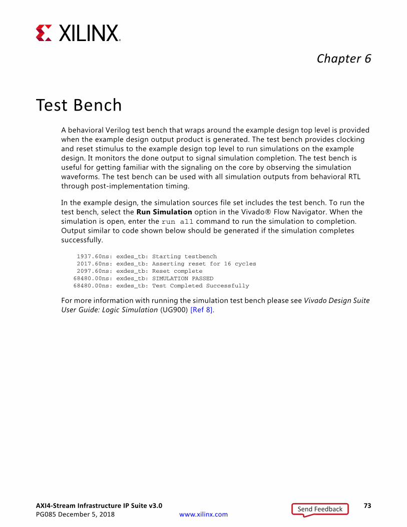
AXI4-Stream Infrastructure IP Suite v3.0 73PG085 December 5, 2018 www.xilinx.com
Chapter 6
Test BenchA behavioral Verilog test bench that wraps around the example design top level is provided when the example design output product is generated. The test bench provides clocking and reset stimulus to the example design top level to run simulations on the example design. It monitors the done output to signal simulation completion. The test bench is useful for getting familiar with the signaling on the core by observing the simulation waveforms. The test bench can be used with all simulation outputs from behavioral RTL through post-implementation timing.
In the example design, the simulation sources file set includes the test bench. To run the test bench, select the Run Simulation option in the Vivado® Flow Navigator. When the simulation is open, enter the run all command to run the simulation to completion. Output similar to code shown below should be generated if the simulation completes successfully.
1937.60ns: exdes_tb: Starting testbench 2017.60ns: exdes_tb: Asserting reset for 16 cycles 2097.60ns: exdes_tb: Reset complete68480.00ns: exdes_tb: SIMULATION PASSED68480.00ns: exdes_tb: Test Completed Successfully
For more information with running the simulation test bench please see Vivado Design Suite User Guide: Logic Simulation (UG900) [Ref 8].
Send Feedback

AXI4-Stream Infrastructure IP Suite v3.0 74PG085 December 5, 2018 www.xilinx.com
Appendix A
UpgradingThis appendix contains information about migrating a design from ISE® to the Vivado® Design Suite, and for upgrading to a more recent version of the IP core. For customers upgrading in the Vivado Design Suite, important details (where applicable) about any port changes and other impact to user logic are included.
Device MigrationIf you are migrating from a 7 series GTX or GTH device to an UltraScale GTH device, the prefixes of the optional transceiver debug ports for single-lane cores are changed from “gt0”, “gt1” to “gt”, and the suffix “_in” and “_out” are dropped. For multi-lane cores, the prefixes of the optional transceiver debug ports gt(n) are aggregated into a single port. For example: gt0_gtrxreset and gt1_gtrxreset now become gt_gtrxreset [1:0]. This is true for all ports, with the exception of the DRP buses which follow the convention of gt(n)_drpxyz.
It is important to update your design to use the new transceiver debug port names. For more information about migration to UltraScale devices, see the UltraScale Architecture Migration Methodology Guide (UG1026) [Ref 10].
Migrating to the Vivado Design SuiteFor information about migrating to the Vivado Design Suite, see the ISE to Vivado Design Suite Migration Guide (UG911) [Ref 4].
Upgrading in the Vivado Design SuiteThis section provides information about any changes to the user logic or port designations that take place when you upgrade to a more current version of this IP core in the Vivado Design Suite.
Send Feedback
AXI4-Stream Infrastructure IP Suite v3.0 75PG085 December 5, 2018 www.xilinx.com
Appendix A: Upgrading
Parameter Changes
There are no parameter changes.
Port Changes
There are no port changes.
Other Changes
There are no other changes.
Send Feedback
AXI4-Stream Infrastructure IP Suite v3.0 76PG085 December 5, 2018 www.xilinx.com
Appendix B
DebuggingThis appendix includes details about resources available on the Xilinx Support website and debugging tools.
TIP: If the IP generation halts with an error, there may be a license issue. See Licensing and Ordering in Chapter 1 for more details.
Finding Help on Xilinx.comTo help in the design and debug process when using the AXI4-Stream Infrastructure IP Suite, the Xilinx Support web page contains key resources such as product documentation, release notes, answer records, information about known issues, and links for obtaining further product support.
Documentation
This product guide is the main document associated with the AXI4-Stream Infrastructure IP Suite. This guide, along with documentation related to all products that aid in the design process, can be found on the Xilinx Support web page or by using the Xilinx Documentation Navigator.
Download the Xilinx Documentation Navigator from the Design Tools tab on the Downloads page. For more information about this tool and the features available, open the online help after installation.
Solution Centers
See the Xilinx Solution Centers for support on devices, software tools, and intellectual property at all stages of the design cycle. Topics include design assistance, advisories, and troubleshooting tips.
Answer Records
Answer Records include information about commonly encountered problems, helpful information on how to resolve these problems, and any known issues with a Xilinx product.
Send Feedback

AXI4-Stream Infrastructure IP Suite v3.0 77PG085 December 5, 2018 www.xilinx.com
Appendix B: Debugging
Answer Records are created and maintained daily ensuring that users have access to the most accurate information available.
Answer Records for this core are listed below, and can also be located by using the Search Support box on the main Xilinx support web page. To maximize your search results, use proper keywords such as
• Product name
• Tool message(s)
• Summary of the issue encountered
A filter search is available after results are returned to further target the results.
Technical Support
Xilinx provides technical support at the Xilinx Support web page for this LogiCORE™ IP product when used as described in the product documentation. Xilinx cannot guarantee timing, functionality, or support if you do any of the following:
• Implement the solution in devices that are not defined in the documentation.
• Customize the solution beyond that allowed in the product documentation.
• Change any section of the design labeled DO NOT MODIFY.
To contact Xilinx Technical Support, navigate to the Xilinx Support web page.
Debug ToolsThere are many tools available to address AXI4-Stream Infrastructure IP Suite design issues. It is important to know which tools are useful for debugging various situations.
Vivado Design Suite Debug Feature
The Vivado® Design Suite debug feature inserts logic analyzer and virtual I/O cores directly into your design. The debug feature also allows you to set trigger conditions to capture application and integrated block port signals in hardware. Captured signals can then be analyzed. This feature in the Vivado IDE is used for logic debugging and validation of a design running in Xilinx devices.
The Vivado logic analyzer is used with the logic debug IP cores, including:
• ILA 2.0 (and later versions)
• VIO 2.0 (and later versions)
Send Feedback
AXI4-Stream Infrastructure IP Suite v3.0 78PG085 December 5, 2018 www.xilinx.com
Appendix B: Debugging
See the Vivado Design Suite User Guide: Programming and Debugging (UG908) [Ref 6].
Reference Boards
Various Xilinx development boards support AXI4-Stream Infrastructure IP Suite. These boards can be used to prototype designs and establish that the core can communicate with the system.
• 7 series evaluation boards
° KC705
° KC724
Hardware DebugHardware issues can range from link bring-up to problems seen after hours of testing. This section provides debug steps for common issues. The Vivado debug feature is a valuable resource to use in hardware debug. The signal names mentioned in the following individual sections can be probed using the ChipScope tool for debugging the specific problems.
General Checks
Ensure that all the timing constraints for the core were properly incorporated from the example design and that all constraints were met during implementation.
• Does it work in post-place and route timing simulation? If problems are seen in hardware but not in timing simulation, this could indicate a PCB issue. Ensure that all clock sources are active and clean.
• If using MMCMs in the design, ensure that all MMCMs have obtained lock by monitoring the LOCKED port.
• If your outputs go to 0, check your licensing.
Interface Debug
AXI4-Stream Interfaces
If data is not being transmitted or received, check the following conditions:
• If transmit <interface_name>_tready is stuck Low following the <interface_name>_tvalid input being asserted, the core cannot send data.
Send Feedback
AXI4-Stream Infrastructure IP Suite v3.0 79PG085 December 5, 2018 www.xilinx.com
Appendix B: Debugging
• If the receive <interface_name>_tvalid is stuck Low, the core is not receiving data.
• Check that the ACLK inputs are connected and toggling.
• Check core configuration.
• Add appropriate core specific checks.
Send Feedback

AXI4-Stream Infrastructure IP Suite v3.0 80PG085 December 5, 2018 www.xilinx.com
Appendix C
Additional Resources and Legal Notices
Xilinx ResourcesFor support resources such as Answers, Documentation, Downloads, and Forums, see Xilinx Support.
Documentation Navigator and Design HubsXilinx Documentation Navigator provides access to Xilinx documents, videos, and support resources, which you can filter and search to find information. To open the Xilinx Documentation Navigator (DocNav):
• From the Vivado® IDE, select Help > Documentation and Tutorials.
• On Windows, select Start > All Programs > Xilinx Design Tools > DocNav.
• At the Linux command prompt, enter docnav.
Xilinx Design Hubs provide links to documentation organized by design tasks and other topics, which you can use to learn key concepts and address frequently asked questions. To access the Design Hubs:
• In the Xilinx Documentation Navigator, click the Design Hubs View tab.
• On the Xilinx website, see the Design Hubs page.
Note: For more information on Documentation Navigator, see the Documentation Navigator page on the Xilinx website.
Send Feedback
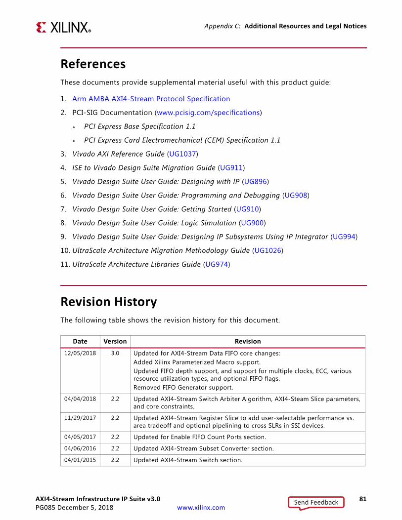
AXI4-Stream Infrastructure IP Suite v3.0 81PG085 December 5, 2018 www.xilinx.com
Appendix C: Additional Resources and Legal Notices
ReferencesThese documents provide supplemental material useful with this product guide:
1. Arm AMBA AXI4-Stream Protocol Specification
2. PCI-SIG Documentation (www.pcisig.com/specifications)
° PCI Express Base Specification 1.1
° PCI Express Card Electromechanical (CEM) Specification 1.1
3. Vivado AXI Reference Guide (UG1037)
4. ISE to Vivado Design Suite Migration Guide (UG911)
5. Vivado Design Suite User Guide: Designing with IP (UG896)
6. Vivado Design Suite User Guide: Programming and Debugging (UG908)
7. Vivado Design Suite User Guide: Getting Started (UG910)
8. Vivado Design Suite User Guide: Logic Simulation (UG900)
9. Vivado Design Suite User Guide: Designing IP Subsystems Using IP Integrator (UG994)
10. UltraScale Architecture Migration Methodology Guide (UG1026)
11. UltraScale Architecture Libraries Guide (UG974)
Revision HistoryThe following table shows the revision history for this document.
Date Version Revision
12/05/2018 3.0 Updated for AXI4-Stream Data FIFO core changes:Added Xilinx Parameterized Macro support.Updated FIFO depth support, and support for multiple clocks, ECC, various resource utilization types, and optional FIFO flags.Removed FIFO Generator support.
04/04/2018 2.2 Updated AXI4-Stream Switch Arbiter Algorithm, AXI4-Steam Slice parameters, and core constraints.
11/29/2017 2.2 Updated AXI4-Stream Register Slice to add user-selectable performance vs. area tradeoff and optional pipelining to cross SLRs in SSI devices.
04/05/2017 2.2 Updated for Enable FIFO Count Ports section.
04/06/2016 2.2 Updated AXI4-Stream Subset Converter section.
04/01/2015 2.2 Updated AXI4-Stream Switch section.
Send Feedback
AXI4-Stream Infrastructure IP Suite v3.0 82PG085 December 5, 2018 www.xilinx.com
Appendix C: Additional Resources and Legal Notices
Please Read: Important Legal NoticesThe information disclosed to you hereunder (the "Materials") is provided solely for the selection and use of Xilinx products. To the maximum extent permitted by applicable law: (1) Materials are made available "AS IS" and with all faults, Xilinx hereby DISCLAIMS ALL WARRANTIES AND CONDITIONS, EXPRESS, IMPLIED, OR STATUTORY, INCLUDING BUT NOT LIMITED TO WARRANTIES OF MERCHANTABILITY, NON-INFRINGEMENT, OR FITNESS FOR ANY PARTICULAR PURPOSE; and (2) Xilinx shall not be liable (whether in contract or tort, including negligence, or under any other theory of liability) for any loss or damage of any kind or nature related to, arising under, or in connection with, the Materials (including your use of the Materials), including for any direct, indirect, special, incidental, or consequential loss or damage (including loss of data, profits, goodwill, or any type of loss or damage suffered as a result of any action brought by a third party) even if such damage or loss was reasonably foreseeable or Xilinx had been advised of the possibility of the same. Xilinx assumes no obligation to correct any errors contained in the Materials or to notify you of updates to the Materials or to product specifications. You may not reproduce, modify, distribute, or publicly display the Materials without prior written consent. Certain products are subject to the terms and conditions of Xilinx's limited warranty, please refer to Xilinx's Terms of Sale which can be viewed at https://www.xilinx.com/legal.htm#tos; IP cores may be subject to warranty and support terms contained in a license issued to you by Xilinx. Xilinx products are not designed or intended to be fail-safe or for use in any application requiring fail-safe performance; you assume sole risk and liability for use of Xilinx products in such critical applications, please refer to Xilinx's Terms of Sale which can be viewed at https://www.xilinx.com/legal.htm#tos.AUTOMOTIVE APPLICATIONS DISCLAIMERAUTOMOTIVE PRODUCTS (IDENTIFIED AS “XA” IN THE PART NUMBER) ARE NOT WARRANTED FOR USE IN THE DEPLOYMENT OF AIRBAGS OR FOR USE IN APPLICATIONS THAT AFFECT CONTROL OF A VEHICLE (“SAFETY APPLICATION”) UNLESS THERE IS A SAFETY CONCEPT OR REDUNDANCY FEATURE CONSISTENT WITH THE ISO 26262 AUTOMOTIVE SAFETY STANDARD (“SAFETY DESIGN”). CUSTOMER SHALL, PRIOR TO USING OR DISTRIBUTING ANY SYSTEMS THAT INCORPORATE PRODUCTS, THOROUGHLY TEST SUCH SYSTEMS FOR SAFETY PURPOSES. USE OF PRODUCTS IN A SAFETY APPLICATION WITHOUT A SAFETY DESIGN IS FULLY AT THE RISK OF CUSTOMER, SUBJECT ONLY TO APPLICABLE LAWS AND REGULATIONS GOVERNING LIMITATIONS ON PRODUCT LIABILITY.© Copyright 2012-2018 Xilinx, Inc. Xilinx, the Xilinx logo, Artix, ISE, Kintex, Spartan, Virtex, Vivado, Zynq, and other designated brands included herein are trademarks of Xilinx in the United States and other countries. AMBA, AMBA Designer, ARM, ARM1176JZ-S, CoreSight, Cortex, and PrimeCell are trademarks of ARM in the EU and other countries. All other trademarks are the property of their respective owners.
10/01/2014 2.2 Updated Table 2-6. Added Device Migration section.
12/18/2013 2.2 Added UltraScale Architecture support.
10/02/2013 2.2 Added Example Design and Test Bench chapters.
03/20/2013 2.1 Updated Tables 2-3 and 2-5 and revised Debugging appendix.
12/18/2012 2.0 Updated for characterization numbers and added Debugging appendix.
10/16/2012 1.0 Initial Xilinx release.
Date Version Revision
Send Feedback