axial compression effect on ductility design of rc
TRANSCRIPT
7/25/2019 Axial Compression Effect on Ductility Design of Rc
http://slidepdf.com/reader/full/axial-compression-effect-on-ductility-design-of-rc 1/11
1
AXIAL COMPRESSION EFFECT ON DUCTILITY DESIGN OF RC
STRUCTURAL WALLS
Y.P. YUEN1 and J.S. KUANG2
ABSTRACT
Reinforced concrete walls can render medium- to high-rise buildings excellent lateral stability andductility. However, modern building design often lead to the vertical structural members subjected tovery high axial compression ratio (ACR), which can deprive the inherent ductility. To evaluate andquantify the effect of ACR on the structural performance of RC walls, a comprehensive statisticalanalysis with 474 sets of experimental data has been conducted. Stipulated limits on ACR and theirevaluation methods in various design codes are then compared. Based on the analysis results, it isfound that EC8 provisions on ACR limits can generally satisfy the target ductility level of ductility.
Nevertheless, more experimental studies on the squat walls behaviour under high ACR are needed todraw a confirmative conclusion.
INTRODUCTION
Catastrophic collapse of reinforced concrete (RC) buildings clearly necessitates dragging down ofvertical structural members, for instance, failure of structural walls can lead to potential overallstructural instability. In view of this, capacity protection of walls and primary columns with the use ofspecial design and detailing approaches is one of the most critical issues in seismic design paradigms.It has been demonstrated in many disastrous earthquakes (Fintel, 1992) that well designed structuralwalls can render excellent lateral stability and drift ductility to medium- to high-rise RC buildingsunder seismic actions. To achieve the goal of capacity design, enhancing and preserving sufficientductility of RC structural walls are done with confinement details, of which requirements aresignificantly influenced by the level of axial force induced on the walls. The 2010 Chile earthquake is
a good example on the effect of high axial forces on seismic performance of RC walls. Post-earthquake field investigations observed that thin walls, with thickness range from 150 to 200mm, inthe newly built high-rise buildings were subjected to higher axial compression and surprisinglysuffered more severe damage than the thicker walls in the old buildings during the earthquake (EERI,2010). Not only in Chile, modern complex structures and super high-rise skyscrapers in other parts ofthe civilised world are also often characterised by high compression forces in the members with highslenderness, as a consequence of architectural designs maximising clear floor heights and usable floorareas. Recent studies (Wallace et al., 2012; Su and Wong, 2006) have indicated that structural wallelements in modern high-rise buildings would sustain axial compression ratios, as high as 0.4 or above,which is already outside the typical range between 0 and 0.2 investigated in experiment.
The effect of axial force on the seismic behaviour of RC walls is known as a posteriori but theyare correlated in multiple aspects. Although the curvature ductility of RC sections can be readily
1 Assistant Professor, Bursa Orhangazi Üniversitesi, Turkey, [email protected] Professor, Hong Kong University of Science and Technology, Hong Kong, [email protected]

7/25/2019 Axial Compression Effect on Ductility Design of Rc
http://slidepdf.com/reader/full/axial-compression-effect-on-ductility-design-of-rc 2/11
2
evaluated at different axial force levels, the relationships of axial force with buckling tendency oflongitudinal reinforcing bars and cyclic fatigue of the members are quite complicate in particularunder seismic loading. Meanwhile, the axial force can also bring in some positive effect on thestructural behaviour such as supressing shear sliding and premature anchorage failure (Kappos, 1996).Hence, the actual seismic responses of the RC walls under significant influence of axial force can becomplicated, given that interactions amongst different axial force effects and failure mechanismsfurther perplex the situation. Nonetheless, both research studies and disastrous earthquakes (Wallaceet al., 2012) have repeatedly revealed that adverse effect brought by axial compression on RC wallsgenerally overwhelms the benefits introduced.
To avert undesirable brittle failures of RC members, on the basis of the work by Chronopoulosand Vinzileou (1995), Eurocode 8 (EC8) stipulates the limits for normalised axial force or also knownas axial force ratio for RC members at various ductility classes, despite the largely scattered results(Tassios, 1996). Chinese and Hong Kong design codes also impose similar requirements as by EC8.Yet, not every modern design code, for instance, New Zealand and ACI codes, takes on the samemeasure to limit the axial compression ratio in the design of RC structures. There is apparently noconsensus amongst different engineering and research communities on whether limiting the axialcompression ratio is crucial to the ductile or capacity design of RC walls withstanding seismic loading.
In view of this issue, this paper presents a revisit and statistical analysis for the effect of axialcompression ratio on seismic performance of RC structural walls, followed by a comparison anddiscussion on the rationale of relevant provisions found in various design codes. The work presentedin this paper would shed light on the justification of the use of axial compression ratio in design of RCwalls and determination of a suitable limit for controlling seismic performance of RC structures.
DEFINITIONS AND EFFECTS OF AXIAL COMPRESSION RATIOS
To parametricise the axial compression effect on the structural performances of RC walls, in theliterature, the axial compression is generally normalised by the concrete uniaxial compressive strengthtimes the sectional area of the concrete member i.e. the axial compression ratio (ACR) is defined as
A f
N
c
(1)
Besides the confinement detailing, aspect ratios, lap and splices, etc., axial compression ratio isa very important indicator in evaluating the expected ductility and fragility of the RC walls duringearthquakes. However, it should not be confused with the limit state design concepts, since the axialcompression ratio alone cannot represent or be used to assess the actual seismic performances of theRC walls.
Axial force has a crucial role in governing the drift ductility of RC walls. An apparent andinstant effect with higher axial compression is reducing the curvature ductility of the walls (Paulay and
Priestley, 1992). The relationship between curvature ductility and axial compression is illustratedin Figure 1. If the strain penetration effect is deemed to be negligible and assuming the plastic hingelength
w pl l 5.0 , the normalised drift capacity and ductility of flexural-controlled wall segments can
then be estimated by the following equation,
5.175.0
11
y
cuw
V y
u
c
l
(2)
where V = vertical aspect ratio ( wl H / ).

7/25/2019 Axial Compression Effect on Ductility Design of Rc
http://slidepdf.com/reader/full/axial-compression-effect-on-ductility-design-of-rc 3/11
Authors should be written like A.Mehmet and M.Ahmet 3
Figure 1. Relationship between curvature ductility and internal forces of walls
By assuming the walls fail in flexural mode, the influence of axial compression ratio on thedisplacement ductility can be evaluated as shown in Figure 4.
Figure 2. Influence of ACR on the displacement ductility of RC walls
Figure 2 shown above has clearly demonstrated the indispensable need of an ACR limit, in viewof the diminishing effectiveness of confinement on enhancing the displacement capacity at high levelof ACR. It is shown that a quite drastic drop in the displacement capacities following the increase ofACR from 10% to 30%, after where the relationship curves become stagnating and tend to converge tothe same value of ductility or ultimate displacement, thus the confinement details become irrelevantthereafter. Meanwhile, it is interestingly observed that high aspect ratios inflict negative effect on theductility but is beneficial to the ultimate displacement, though it is less sensitive to aspect ratios incomparison with the ductility. The realistic relation between ACR and displacement capacity is farmore complicated, what will be seen later, owing to the fact that each influential factor can interactwith other ones resulting in complex overall structural behaviour, for instance, various factors
including axial force, aspect ratio, stiffness, cracks, etc. can come into play of the elasto-plastic buckling of walls.

7/25/2019 Axial Compression Effect on Ductility Design of Rc
http://slidepdf.com/reader/full/axial-compression-effect-on-ductility-design-of-rc 4/11
4
STATISTICAL ANALYSIS ON THE EFFECT OF ACR
Besides the confinement detailing, aspect ratios, lap and splices, etc., axial compression ratio is a veryimportant indicator in evaluating the expected ductility and fragility of the RC walls duringearthquakes. However, it should not be confused with the limit state design concepts, since the axialcompression ratio alone cannot represent or be used to assess the actual seismic performances of theRC walls. Besides the confinement detailing, aspect ratio and axial compression, the ductility andgeneral seismic performances of RC columns can be influenced by other various factors, for instancethe anchorage, loading pattern, etc., of which effect in turn interact with confinement and axial loadeffect. In view of this complicated behaviour, the quantification of the effect of axial compression onRC walls’ seismic performance has been very much relying on experimental data.
Evaluation and quantification for the effect of axial force ratio on RC walls’ seismic performance were carried out with a comprehensive statistical study. Total 474 sets of data, composedof experimental results of small to full-scale RC walls of various shapes and detailing methods, werecollected from literatures. The gathered load-displacement data are then analysed, where thedefinitions of yield displacement, ultimate displacement and displacement ductility of the loadingcurves are based on Park (1989). In the collected database, more than 60% of the tests are conducted
under relatively low axial force ratio below 0.05; in contrast, there are only about 15% and 7 % weretested with axial force ratio above 0.15 and 0.30 respectively. Nonetheless, these high axial force testsdemonstrated that the RC walls would fail in a very different manner such as out-of-plane buckling,resembling to the observed damage modes of the walls in the 2010 Chile earthquake. RC walls failedin out-of-buckling generally are very brittle exhibiting low ductility, and the classical ductilityevaluation methods assuming in-plane flexural failure are no longer applicable to these walls.
The relationship between ultimate displacement capacity and axial compression ratio of varioustypes of RC shear walls is also plotted in Figure 3. Similar to the analytical study (Figure 2) presented
before, there is a trend of diminishing ultimate displacement capacity of slender walls with increasingaxial compress ratio, as shown in Figure 3(b), owing to the reduction in neutral axial depth, low cyclefatigue effect as well as potential out-of-plane buckling. Nevertheless, the ultimate displacementcapacity of squat walls tends to increase with axial compression ratio (Figure 3(c)). This reversed
trend is actually due to the fact that the shear strength and sliding resistance of cracks in the squatwalls are enhanced by axial compression.
On the other hand, Figure 4a shows the relationship between drift ductility and axial force ratioof RC walls of various kinds. It can be seen that RC walls can easily achieve high ductility ( 6 )
at low axial force ratio ( %10 ) as long as the boundary elements are well detailed and designed.
However, when the axial compression ratio increases to above 20%, the RC walls can only barelymaintain moderate ductility ( 64 ) and special detailing methods like composite-reinforced
boundary elements are necessary in order to acquire high ductility. Above 35% axial compressionratio pre-emptive out-of-plane buckling can be the dominating failure mode as reported in theliteratures (Zhang and Wang, 2000), resulting in RC walls not being suitable to provide lateral andvertical resistances in seismic design. It is recognised that squat RC walls with aspect ratios ( L H / )
lower than 1.5 would be prone to shear failure in particularly sliding shear failure rather than flexuralfailure and the displacement ductility is not necessarily reduced by increase of axial compression. Incontrast to slender RC walls (Fig. 4b), the ductility of squat RC walls (Fig. 4c) is less influenced byaxial compression ratio that the ductility generally maintains in the range 42 .
Another important structural property of RC walls related to the axial compression is the shearstrength. For comparison purpose, the peak base shears reported by the tests in the database are furthernormalised by the following equation:
wc
p
n A f
V v
5.0 (3)
where w A = web area of the wall.

7/25/2019 Axial Compression Effect on Ductility Design of Rc
http://slidepdf.com/reader/full/axial-compression-effect-on-ductility-design-of-rc 5/11
Authors should be written like A.Mehmet and M.Ahmet 5
(a)
(b) (c)Figure 3. Relationship between ultimate displacement ratio and ACR: (a) all types; (b) slender walls
(H/L > 1.5); and (c) squat walls (H/L < 1.5)
(a)

7/25/2019 Axial Compression Effect on Ductility Design of Rc
http://slidepdf.com/reader/full/axial-compression-effect-on-ductility-design-of-rc 6/11
6
(b) (c)Figure 4. Relationship between displacement ductility and ACR: (a) all types; (b) slender walls (H/L >
1.5); and (c) squat walls (H/L < 1.5)
Figure 5 shows the relationship between normalised shear strength and axial compression ratio.Higher axial compression tends to increase the shear strength of all types of RC walls, in particularsquat RC walls (Figure 5c). This is because axial compression not only can enhance the shear strengthof walls, but also the moment resistance in some cases (Wallace et al., 2012). Nevertheless, theenhanced shear strength attributed to axial compression generally cannot compensate for the adverseeffect of reduced drift capacity, as after all, the system ductility is far more important than the strengthin seismic design.
CODES PROVISIONS ON AXIAL COMPRESSION RATIOS
In view of the adverse effect of axial compression on the seismic performance of RC structural walls
as illustrated in the last section, most of the modern design codes of practice for RC structuresstipulate upper limits of the axial compression ratio. RC walls with an axial compression ratio beyondthe limits are generally deemed to be ineffective in resisting seismic action even with confinementdetailing in the critical regions (expected plastic hinges) of the members. These provisions, inaddition to confinement detailing, intend to ensure that sufficient drift ductility and axial forcecarrying capacity can be retained in RC structures during earthquakes or other exceptional load cases.
Eurocode 8 (EN 1998-1:2004)EC8 stipulates upper limits of axial compression ratios (normalised axial force) for ductile walls andcolumns designed for ductility classes moderate and high (DCM and DCH), but no restrictions forductility class low (DCL) as follows
2004):1-1998EN(BS
DCL
DCM
DCH
4.0
35.0,
ccd
EC ED
A f
N (4)
where EC ED N , = design axial force from the analysis for the seismic design situation and cd f =
the design (factored with safety factor 1.5) cylinder strength of concrete under uniaxial compression at28 days. The design axial force in Eq. 4 consists of two major components- (i) axial force induced byrepresentative gravity action and (ii) axial force induced by seismic action. Although axial forcesincurred in cantilever walls by seismic loads are relatively minor compared with permanent gravity
action in general, coupled shear walls would have to bear significantly extra axial forces incurred byseismic actions due to the coupling action aggregated from the shear forces of the coupling beams.

7/25/2019 Axial Compression Effect on Ductility Design of Rc
http://slidepdf.com/reader/full/axial-compression-effect-on-ductility-design-of-rc 7/11
Authors should be written like A.Mehmet and M.Ahmet 7
(a)
(b) (c)Figure 4. Relationship between shear strength and ACR: (a) all types; (b) slender walls (H/L > 1.5);
and (c) squat walls (H/L < 1.5)
Therefore, the definition of the axial compression ratio (ACR) used by EC8 can be consideredthe most appropriate description of realistic stress states experienced by the RC structures during
earthquakes. Actually, the limits of ACR stipulated in EC8 can be readily compared withexperimental studies to see whether the provisions can assure sufficient ductility of the RC members.
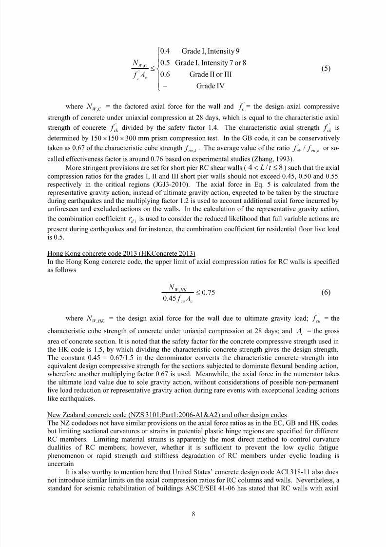
Chinese seismic design code 2010 (GB50011-2010) In the Chinese seismic design code, the upper limits of axial compression ratios for RC shear walls(sectional aspect ratio L/t>8) take different values under different design fortification earthquakeintensities and structure grades (4 classes from I to IV: grade I structures have high drift ductility,grade II and III structures have moderate to high drift ductility, and grade IV structures have relativelylow drift ductility) as follows
7/25/2019 Axial Compression Effect on Ductility Design of Rc
http://slidepdf.com/reader/full/axial-compression-effect-on-ductility-design-of-rc 8/11
8
IVGrade
IIIorIIGrade
8or7IntensityI,Grade
9IntensityI,Grade
6.0
5.0
4.0
'
,
c
C W
A f
N
c
(5)
whereC W N , = the factored axial force for the wall and '
c f = the design axial compressive
strength of concrete under uniaxial compression at 28 days, which is equal to the characteristic axial
strength of concrete 'ck f divided by the safety factor 1.4. The characteristic axial strength '
ck f is
determined by 300150150 mm prism compression test. In the GB code, it can be conservatively
taken as 0.67 of the characteristic cube strengthk cu f , . The average value of the ratio
k cuck f f ,' / or so-
called effectiveness factor is around 0.76 based on experimental studies (Zhang, 1993).More stringent provisions are set for short pier RC shear walls ( 8/4 t L ) such that the axial
compression ratios for the grades I, II and III short pier walls should not exceed 0.45, 0.50 and 0.55respectively in the critical regions (JGJ3-2010). The axial force in Eq. 5 is calculated from the
representative gravity action, instead of ultimate gravity action, expected to be taken by the structureduring earthquakes and the multiplying factor 1.2 is used to account additional axial force incurred byunforeseen and excluded actions on the walls. In the calculation of the representative gravity action,
the combination coefficient id r is used to consider the reduced likelihood that full variable actions are
present during earthquakes and for instance, the combination coefficient for residential floor live loadis 0.5.
Hong Kong concrete code 2013 (HKConcrete 2013) In the Hong Kong concrete code, the upper limit of axial compression ratios for RC walls is specifiedas follows
75.045.0
, ccu
HK W
A f N (6)
where HK W N , = the design axial force for the wall due to ultimate gravity load; cu f = the
characteristic cube strength of concrete under uniaxial compression at 28 days; and c A = the gross
area of concrete section. It is noted that the safety factor for the concrete compressive strength used inthe HK code is 1.5, by which dividing the characteristic concrete strength gives the design strength.The constant 0.45 = 0.67/1.5 in the denominator converts the characteristic concrete strength intoequivalent design compressive strength for the sections subjected to dominate flexural bending action,wherefore another multiplying factor 0.67 is used. Meanwhile, the axial force in the numerator takes
the ultimate load value due to sole gravity action, without considerations of possible non-permanentlive load reduction or representative gravity action during rare events with exceptional loading actionslike earthquakes.
New Zealand concrete code (NZS 3101:Part1:2006-A1&A2) and other design codes The NZ codedoes not have similar provisions on the axial force ratios as in the EC, GB and HK codes
but limiting sectional curvatures or strains in potential plastic hinge regions are specified for differentRC members. Limiting material strains is apparently the most direct method to control curvaturedualities of RC members; however, whether it is sufficient to prevent the low cyclic fatigue
phenomenon or rapid strength and stiffness degradation of RC members under cyclic loading isuncertain
It is also worthy to mention here that United States’ concrete design code ACI 318-11 also does
not introduce similar limits on the axial compression ratios for RC columns and walls. Nevertheless, astandard for seismic rehabilitation of buildings ASCE/SEI 41-06 has stated that RC walls with axial

7/25/2019 Axial Compression Effect on Ductility Design of Rc
http://slidepdf.com/reader/full/axial-compression-effect-on-ductility-design-of-rc 9/11
Authors should be written like A.Mehmet and M.Ahmet 9
loads greater than 35% of nominal axial load strength 0 P shall not be considered effective in resisting
seismic forces. The Canadian concrete code CSA A23.3-04 (R2010) also stated that for flexural
members with factored axial loads in excess of 0.35 0 P shall have a nominal resistance greater than the
induced member force, i.e. not to be designed to form potential plastic hinges and dissipate energy inany circumstances under seismic effects.
Comparisons of the Code ProvisionsAlthough the definitions of the axial force ratios in the EC, GB and HK codes are somehow not alike
particularly the axial forces in the numerators, the compressive strength terms in the denominators can
be readily transformed to characteristic cylindrical strength 5.1/8.0 cd cuc f f f for comparisons.
Table 1 summarises the key comparisons of the provisions on the axial compression ratios defined inthe three codes.
Table 1. Comparisons of codes provisions on ACRs for RC walls
CoP-SUC 2013 GB50011-2010* EN 1998-1:2004
Original definition of ACRsccu
HK W
A f
N
45.0,
cc
C W
A f
N '
,
ccd
EC ED
A f
N ,
Limit(s) 75.0
IVGrade
IIIorIIGrade
8or7IntensityI,Grade
9IntensityI,Grade
6.0
5.0
4.0
DCL
DCM
DCH
4.0
35.0
Seismic/lateral forces effects × ×
Variable load reduction ×
Renormalised ACRs limits wrt f c42.0,
cc
HK W
A f
N
IVGradeIIIorIIGrade
8or7IntensityI,Grade
9IntensityI,Grade
34.0
28.0
22.0
,
cc
C W
A f
N
DCL
DCM
DCH
26.0
23.0,
cc
EC ED
A f
N
* Limits for grades I, II and III short pier RC shear walls ( 8/4 B H ) are 0.45, 0.50 and 0.55 respectively.
The ACR limits stipulated in the GB code are resemble to those in the EC8, but again thecombinations of actions for calculating the axial forces are different in the two codes as mentioned
before. For cantilever walls, the GB code is virtually more stringent because of the safety factor 1.2 isused to amplify the action. But for coupled shear walls, it is not conclusive that which one of the twocodes is more conservative, since the 1.2 factor may not be sufficient to cover the exceeding axialforces induced by the coupling action. Nevertheless, the EC8 provide a more realistic assessment forthese cases by taking in considerations of seismic or generally lateral forces effects. At the first sightlooking at the last row in Table 1, the HK code has the least stringent limit on the ACR for RC walls
compared with the other two codes. But it should be noticed that the axial force in the numerator isgenerally much larger, given that full ultimate gravity action is considered instead of representativegravity action.
If the figure of relationship between displacement ductility and ACR (Figure 4) is introducedagain and plotted together with the code specified limits on ACRS, the expected achievable ductilityof RC walls can be closely evaluated as shown in Figure 5. In EC8, for multi-storey uncoupled RCwalls building with fundamental period T 1 larger than the period T c at the upper limit of the constantacceleration region of the responses spectrum, displacement ductility factor is equal to the
behaviour factor q (EC8), of which basic values take on 3.0 and 4.8 for DCM and DCH respectively.EC8 provisions undoubtedly satisfy this target level of ductility, provided that boundary elements are
properly detailed. The grade I structures designed to GB code can also satisfy this target but the gradeII or III structures may only have restricted inherent ductility and are susceptible to out-of-plane
buckling. However, the HK code limit is somehow unjustifiable in a sense of targeting to control theductility and is way beyond the other limits stipulated in the GB and EC8 codes.

7/25/2019 Axial Compression Effect on Ductility Design of Rc
http://slidepdf.com/reader/full/axial-compression-effect-on-ductility-design-of-rc 10/11
10
(a)
(b) (c)Figure 5. Codes specified ACR limits and expected achievable ductility: (a) all types; (b) slender walls
(H/L > 1.5); and (c) squat walls (H/L < 1.5)
Figure 5a can be deaggregated into two cases of slender walls (H/L > 1.5) and squat walls (H/L < 1.5)as what has been done before, and the resulted plots are shown in Figs. 8b and c. For the slender walls,it can be seen that there is still room for the ACR limits stipulated in EC8 to be relaxed, for instance,to 0.25 and 0.3 for DCH and DCM; whereas for the squat wall, the ACR limits are seemingly neededto be tightened up. However, Figure 3c indicates that axial force, meanwhile, tends to increase theultimate displacement of squat RC walls, which is clearly beneficial in the state-of-the-artdisplacement based design methods. One may conclude that the squat walls are not suitable to bedesigned to allow inelastic deformation and as an energy dissipating element. Obviously, in view ofthe scarce data, more experimental studies on the squat walls behaviour under high ACR are necessary
before confirmative conclusions can be drawn.
Concluding remarks
Excellent lateral stability and drift ductility of reinforced concrete walls are of important buildings indesign of medium- to high-rises building against seismic effects and other exceptional loading cases.
However, walls in modern buildings are often subjected to very high axial compression, which has been pushing the limits of the conventional design and analysis theories.

7/25/2019 Axial Compression Effect on Ductility Design of Rc
http://slidepdf.com/reader/full/axial-compression-effect-on-ductility-design-of-rc 11/11
Authors should be written like A.Mehmet and M.Ahmet 11
A comprehensive statistical analysis with 474 sets of experimental data has been conducted toinvestigate the effect of axial compression ratio (ACR) on the structural performance of various typesof RC walls. It is shown that the ductility of the walls is generally diminishing with increasing ofACR and this trend is particularly noticeable for slender walls with aspect ratio greater 1.5. Provisionson the limits of ACR stipulated in various codes are then compared and the expected attainableductility of RC walls designed to different codes are evaluated against the statistical analysis results.
Based on the analysis results, it is found that EC8 provisions on ACR limits can generallysatisfy the target ductility level of ductility. Nevertheless, ACR limits may take on different values forthe slender and squat walls, in view of their distinct structural behaviour. The ACR limits for slenderwalls may be relaxed, whereas the ACR limits for squat walls are seemingly needed to be tightened up.Obviously, there is a need of more experimental studies on the squat walls behaviour under high ACR
before confirmative conclusions can be drawn.
Acknowledgement
The support of Hong Kong RGC under grand No. 614011 is gratefully acknowledged.
REFERENCES
American Concrete Institute: ACI 318-11 (2011) Building Code Requirements for Structural Concrete andCommentary, Farmington Hills, MI.
American Society of Civil Engineers: ASCE/SEI 41 (2006) Seismic rehabilitation of existing buildings. Reston,Virginia.
Canadian Standard Association: CSA:A23.3-04 (2010) Design of Concrete Structures. Ontario, Canada.CEN: European Standard EN 1998-1:2004 (2004) Eurocode 8: Design of structures for earthquake resistance,
Part 1: General rules, seismic actions and rules for buildings. Comité Européen de Normalisation,Brussels.
Chronopoulos MP, Vinzileou E (1995) “Confinement of RC columns”, European Seismic Design Practice (A. S.,
Elnashai ed.), Balkema, Rotterdam, 341-348.Fintel M (1992) “Need For Shear Walls in Concrete Buildings for Seismic Resistance: Observations on ThePerformance of Buildings With Shear Walls In Earthquakes Of The Last Thirty Years”, Concrete Shear
in Earthquake, edited by Hsu and Mau, Elsevier Science Publishers, Inc., London-New York, 34-42.HKSAR Building Department (2013) Code of Practice for Structural Use of Concrete 2013, The Government of
the HKSAR, Hong Kong.Kappos A, Penelis GG (1996) Earthquake Resistant Concrete Structures. CRC Press, Boca Raton.
National Standard of the People’s Republic of China (2010) Code for Seismic Design of Buildings (GB 50011-2010), China Architecture & Building Press, Beijing. (in Chinese)
National Standard of the People’s Republic of China (2010) Technical Specification for Concrete Structures ofTall Building (JGJ 3-2010). China Architecture & Building Press, Beijing.
Paulay T, Priestley MJN (1992) Seismic Design of Reinforced Concrete and Masonry Buildings. John Wiley &Sons, New York.
Park R (1989) “Evaluation of ductility of structures and structural assemblages from laboratory testing”, Bulletinof the New Zealand Society for Earthquake Engineering , 22(3): 155–166.
Standards New Zealand (2006) Concrete Structure Standard-The Design of Concrete Structures IncorporatingAmendment No.1 & 2 (NZS 3101:Part 1:2006-A1&A2), Wellington, New Zealand.
Su RKL, Wong SM (2006) “A survey on axial load ratios of medium-rise residential buildings in Hong Kong”, HKIE Transactions, 14(3):. 40-46.
Tassios TP (1996) “Advances in earthquake-resistant design concrete structures”, 11th World Conference on Earthquake Engineering, Acapulco, Mexico, paper No. 2171.
Wallace JW, Massone LM, Bonelli P, Dragovich J, Lagos R, Lüders C, Moehle J (2012) “Damage andimplications for seismic design of RC structural wall buildings”, Earthquake Spectra, 28(S1):281-S299.
Zhang QX (1993) Concrete Structure Design: Basic Theory, Methods and Examples. Jiangsu Science andTechnology Publishing House, Jiangsu. (in Chinese)
Zhang Y and Wang Z (2000) “Seismic behaviour of reinforced concrete shear walls subjected to high axial
loading”, ACI Structural Journal , 97(5): 739-750.