axl f rs uni 1h - digi-key sheets/phoenix contact pdfs/axl... · axl f rs uni 1h 8533_en_02_c01...
TRANSCRIPT

1 Description
Axioline F communication module for serial data
transmission, 1 interface can be parameterized as
RS-485/RS-422 or RS-232
AXL F RS UNI 1H
© PHOENIX CONTACT
Data sheet
The module is designed for use within an Axioline F station.
It is used to operate standard I/O devices with serial inter-
faces on a bus system.
Features
– A serial input and output channel in RS-232, RS-422
and RS-485 format
– Various protocols supported
– Transmission speed can be set up to 250000 baud
– Parameterization via the PDI channel
– Device type label stored
– Diagnostic and status indicators
This data sheet is only valid in association with the UM EN AXL SYS INST user manual.
Make sure you always use the latest documentation.
It can be downloaded from the product at phoenixcontact.net/products.
8533_en_02_C01 2013-08-13

AXL F RS UNI 1H
8533_en_02_C01 PHOENIX CONTACT 2
2 Table of contents
1 Description .............................................................................................................................. 1
2 Table of contents ..................................................................................................................... 2
3 Ordering data .......................................................................................................................... 3
4 Technical data ......................................................................................................................... 3
5 Internal circuit diagram ............................................................................................................ 5
6 Terminal point assignment....................................................................................................... 6
7 Connection notes .................................................................................................................... 7
8 Connection examples.............................................................................................................. 7
9 Local status and diagnostic indicators ..................................................................................... 9
10 Serial interfaces..................................................................................................................... 11
11 Data storage and transmission .............................................................................................. 12
12 Process data.......................................................................................................................... 14
13 Process data word 0 .............................................................................................................. 15
14 Commands............................................................................................................................ 17
15 Parameter, diagnostics and information (PDI) ....................................................................... 20
16 Standard objects ................................................................................................................... 21
17 Application objects ................................................................................................................ 24
18 Device descriptions ............................................................................................................... 30

AXL F RS UNI 1H
8533_en_02_C01 PHOENIX CONTACT 3
Description Type Order No. Pcs. / Pkt.
Axioline F communication module for serial data transmission, 1 interface
can be parameterized as RS-485/RS-422 or RS-232 (including bus base
module and plugs)
AXL F RS UNI 1H 2688666 1
3 Ordering data
Accessories Type Order No. Pcs. / Pkt.
Axioline F bus base module for housing type H (Replacement item) AXL F BS H 2700992 5
Axioline plug set (e.g., for AXL DI 16/1) (Replacement item) AXL CNS 2L-O/D/UI/E1/E2 2700985 1
Zack marker strip for Axioline (device labeling), in 2 x 20.3 mm pitch, un-
printed, 25-section, for individual labeling with B-STIFT 0.8, X-PEN, or
CMS-P1-PLOTTER (Marking)
ZB 20,3 AXL UNPRINTED 0829579 25
Zack marker strip, flat, in 10 mm pitch, unprinted, 10-section, for individual
labeling with M-PEN 0,8, X-PEN, or CMS-P1-PLOTTER (Marking)
ZBF 10/5,8 AXL UNPRINTED 0829580 50
Axioline shield connection set (contains 2 busbar holders and 2 SK 5 shield
connection clamps)
AXL SHIELD SET 2700518 1
Insert label, Roll, white, Unlabeled, Can be labeled with: Thermomark R,
Thermomark X, Thermomark S, Mounting type: Snapped into marker car-
rier, Lettering field: 35 x 28 mm (Marking)
EMT (35X28)R 0801602 1
Documentation Type Order No. Pcs. / Pkt.
User manual, English, Axioline: System and installation UM EN AXL SYS INST - -
Dimensions (nominal sizes in mm)
Width 35 mm
Height 126.1 mm
Depth 54 mm
Note on dimensions The depth is valid when a TH 35-7.5 DIN rail is used (according to EN 60715).
4 Technical data
35 54
12
2,4
12
6,1
General data
Color Military gray RAL 7042
Weight 135 g
Mounting type DIN rail
Ambient temperature (operation) -25 °C ... 60 °C
Ambient temperature (storage/transport) -40 °C ... 85 °C
Permissible humidity (operation) 5 % ... 95 % (no condensation)

AXL F RS UNI 1H
8533_en_02_C01 PHOENIX CONTACT 4
Permissible humidity (storage/transport) 5 % ... 95 % (no condensation)
Air pressure (operation) 70 kPa ... 106 kPa (up to 3000 m above sea level)
Air pressure (storage/transport) 70 kPa ... 106 kPa (up to 3000 m above sea level)
Degree of protection IP20
Protection class III, IEC 61140, EN 61140, VDE 0140-1
General data
Connection data
Name Axioline plug
Connection method Push-in technology
Conductor cross section solid / stranded 0.2 mm² ... 1.5 mm²
Conductor cross section [AWG] 24 ... 16
Interface Axioline F local bus
Connection method Bus base module
Transmission speed 100 MBit/s
Interface RS-232, RS-485, RS-422
Connection method Push-in technology
Transmission speed 110 Bit/s ... 250 kBit/s (can be parameterized)
Transmission physics Copper
Protocols supported Transparent, end-to-end, XON/XOFF, Modbus RTU (master support)
Input buffer 4 kByte
Output buffer 1 kByte
Data bits 5 8
Stop bits 1 or 2
Communications power
The I/O is also supplied from the communications power UBus.
The I/O supply is electrically isolated from the local bus.
Communications power Ubus 5 V DC (via bus base module)
Current consumption from Ubus typ. 200 mA, max. 240 mA
PROFIBUS telegram data
Required parameter data 14 Byte
Need for configuration data 7 Byte
Electrical isolation/isolation of the voltage areas
5 V supply (logic)/functional earth ground 500 V AC, 50 Hz, 1 min
5 V supply (logic)/5 V supply (I/O) 500 V AC, 50 Hz, 1 min
5 V supply (I/O)/functional earth ground 500 V AC, 50 Hz, 1 min
Mechanical tests
Vibration resistance in acc. with IEC 60068-2-6 5 g
Shock test in acc. with IEC 60068-2-27 30g, 11 ms period, half-sine shock pulse
Bump endurance test according to EN 60068-2-27 10 g

AXL F RS UNI 1H
8533_en_02_C01 PHOENIX CONTACT 5
5 Internal circuit diagram
Figure 1 Internal wiring of the terminal points
Key:
Conformance with EMC Directive 2004/108/EC
Noise immunity test in accordance with EN 61000-6-2
Electrostatic discharge (ESD) EN 61000-4-2/IEC 61000-4-2 Criterion B; 6 kV contact discharge, 8 kV air discharge
Electromagnetic fields EN 61000-4-3/IEC 61000-4-3 Criterion A; Field intensity: 10 V/m
Fast transients (burst) EN 61000-4-4/IEC 61000-4-4 Criterion B, 2 kV
Transient surge voltage (surge) EN 61000-4-5/IEC 61000-4-5 Criterion B; DC supply lines: ±0.5 kV/±0.5 kV (symmetrical/asymmetrical)
Conducted interference EN 61000-4-6/IEC 61000-4-6 Criterion A; Test voltage 10 V
Noise emission test according to EN 61000-6-3
Radio interference properties EN 55022 Class B
Error messages to the higher level control or computer system
I/O supply failure Yes
Approvals
For the latest approvals, please visit phoenixcontact.net/products.
D
UI
E1
E2
UBus
Local busµC
FE
5 V
5 V
5 V
RS-485
RS-232
RS-232
RS-485
12x
Local bus Axioline F local bus
(hereinafter referred to as local bus)
Microcontroller
Optocoupler
Diagnostic and status indicators
RS-485/422/232 interface
DC/DC converter with electrical isolation
Coupling network
Electrically isolated area
µC

AXL F RS UNI 1H
8533_en_02_C01 PHOENIX CONTACT 6
6 Terminal point assignment
Figure 2 Terminal point assignment
0300131023203330
a1
a2
b1
b2
00
10
20
30
01
11
21
31
02
12
22
32
03
13
23
33
a1a2b1b2
Plug 1
Terminal
point
Color Assignment
a1, a2 Red Not used (bridged internally)
b1, b2 Blue Not used (bridged internally)
You can use plug 1 for potential routing of the
24 V supply voltage, however the voltage is
not used by the module.
Plug 2 RS-485 RS-422 Notes
Terminal point Color Signal Description Description
00 Orange TxD+ Not used Transmit data positive
10 Orange RxD+ Transmit/receive data Receive data positive
20 Orange RxD+ Transmit/receive data Receive data Positive; for external
bridge to 30
30 Orange R+ Termination resistor Termination resistor Positive pole; for external
bridge to 20
01 Orange TxD- Not used Transmit data negative
11 Orange RxD- Transmit/receive data Receive data negative
21 Orange RxD- Transmit/receive data Receive data Negative; for external
bridge to 31
31 Orange R- Termination resistor Termination resistor Negative pole; for external
bridge to 21
Plug 3: RS-232
Terminal point Color Signal Description
02 Orange RxD Serial data input
12 Orange RTS Request to send Request to send; handshake signal; output
22 Orange DTR Data terminal ready Startup request to the connected device; handshake
signal; output
32 Orange DCD Data carrier detect Connected device ready to operate; handshake sig-
nal; input
03 Orange TxD Serial data output
13 Orange CTS Clear to send Permission to send; connected device ready to re-
ceive; handshake signal; input
23 Orange DSR Data set ready Connected device ready to operate; handshake sig-
nal; input
33 Orange GND Ground for the serial interface

AXL F RS UNI 1H
8533_en_02_C01 PHOENIX CONTACT 7
7 Connection notes
– Connect the shield to a busbar before the module
– Fit the receive signals of the RS-485 or RS-422 network
with a termination resistor at the relevant end point.
– If you use the integrated termination resistor, the polar-
ization of the data cable will also be active.
8 Connection examples
8.1 RS-485: module as the network end point
Figure 3 RS-485 interface wiring:
Module as the network end point
8.2 RS-485: module in the network center
Figure 4 RS-485 interface wiring:
Module in the network center
Operating mode Special feature Notes Image
RS-485 Module as the network end point Termination resistor required Figure 3
RS-485 Module in the network center Figure 4
RS-422 Module is last receiver Termination resistor required Figure 5
RS-232 Four-wire handshake Figure 6
RS-232 Without handshake Figure 7
00
10
20
30
01
11
21
31
02
12
22
32
03
13
23
33
1 2
RS-485 RS-485
R-
TxD+
TxD-
RxD-
RxD-
00
01
10
20
11
21
R+ 30
31
RxD+
RxD+
AXL RS UNI
RS-485
00
10
20
30
01
11
21
31
02
12
22
32
03
13
23
33
1 2
RS-485RS-485 RS-485
R-
TxD+
TxD-
RxD-
RxD-
00
01
10
20
11
21
R+ 30
31
RxD+
RxD+
AXL RS UNI
RS-485RS-485

AXL F RS UNI 1H
8533_en_02_C01 PHOENIX CONTACT 8
8.3 RS-422
Figure 5 RS-422 or RS-485 interface wiring, full duplex
8.4 RS-232: With 4-wire handshake
Figure 6 RS-232 interface wiring: four-wire handshake
8.5 RS-232: Without handshake
Figure 7 RS-232 interface wiring: without handshake
For wiring without handshake, insert a bridge between ter-
minal points 22 (DTR) and 13 (CTS).
00
10
20
30
01
11
21
31
02
12
22
32
03
13
23
33
1 2
R-
TxD+
TxD-
RxD-
RxD-
00
01
10
20
11
21
R+ 30
31
RxD+
RxD+
AXL RS UNI
RS-422
00
10
20
30
01
11
21
31
02
12
22
32
03
13
23
33
DT
R
CT
S
Tx
D
Rx
D
00
10
20
30
01
11
21
31
02
12
22
32
03
13
23
33
Tx
D
Rx
D

AXL F RS UNI 1H
8533_en_02_C01 PHOENIX CONTACT 9
9 Local status and diagnostic indicators
Figure 8 Local status and diagnostic indicators
E2
D
UI
E1
30 3231 33
20 2221 23
10 1211 13
00 0201 03
Plug 1
Designa-
tion
Color Meaning State Description
D Red/yel-
low/green
Diagnostics of local bus communication
Power down OFF Device in (power) reset.
Not connected Red flash-
ing
Device operating, but there is no connection to previous device.
Reset Red ON Application reset
Device operating, but there is still a connection to the previous de-
vice, the application is reset.
Ready Yellow ON Device operating, there is still a connection to the previous device,
but the device has not yet detected a valid cycle after power on.
Connected Yellow
flashing
Valid data cycles have been detected, but the device is (not) yet
part of the current configuration.
Device applica-
tion not active
Green/yel-
low alter-
nating
Valid data cycles are being detected.
The master application set the output data to valid, however, the
slave application has not set the input data to valid as yet.
Active Green
flashing
Device operating, communications within the station is OK.
The master application does not read the input data.
(The connection to the controller has not yet been established, for
example.)
Run Green ON Valid data cycles are being detected. All data is valid
UI Green I/O voltage ON I/O supply voltage is present (generated from UL)
OFF I/O supply voltage is not present (generated from UL)
E1 Red Peripheral fault ON I/O error present.
OFF No I/O error.
E2 Red Channel error ON Channel error present.
OFF Channel error not present.

AXL F RS UNI 1H
8533_en_02_C01 PHOENIX CONTACT 10
Plug 2: RS-485/422
Designation Color State Description
00 TxD Yellow ON Module is transmitting data to the connected device
OFF Module is not transmitting data
10 - - - Not used
20 - - - Not used
30 RS-485 Yellow ON Module is parameterized for RS-485
OFF Module is not parameterized for RS-485
01 RxD Yellow ON Module is receiving data from the connected device
OFF Module is not receiving data
11 - - - Not used
21 - - - Not used
31 RS-422 Yellow ON Module is parameterized for RS-422
OFF Module is not parameterized for RS-422
Plug 3: RS-232
Designation Color State Description
02 RxD Yellow ON Module is receiving data from the connected device
OFF Module is not receiving data
12 RTS Yellow Request to send
ON Handshake signal is set by the module
OFF Handshake signal is not set
22 DTR Yellow Data terminal ready
ON Handshake signal is set by the module
OFF Handshake signal is not set
32 DCD Yellow Data carrier detect
ON Handshake signal is set by partner
OFF Handshake signal is not set
03 TxD Yellow ON Module is transmitting data to the connected device
OFF Module is not transmitting data
13 CTS Yellow Clear to send
ON Handshake signal is set by partner
OFF Handshake signal is not set
23 DSR Yellow ON Data set ready
ON Handshake signal is set by partner
OFF Handshake signal is not set
33 RS-232 Yellow ON Module is parameterized for RS-232
OFF Module is not parameterized for RS-232
Channel errors are errors that can be associ-
ated with a channel.
Periphery errors are errors that affect the en-
tire module.
For more information on the meaning of local
diagnostic and status indicators, please refer
to the UM EN AXL SYS INST user manual.

AXL F RS UNI 1H
8533_en_02_C01 PHOENIX CONTACT 11
10 Serial interfaces
10.1 RS-232
The RS-232 interface on the terminal represents some form
of DTE (data termination equipment).
This means that plug 2 terminal point 2.1 (TxD) is always
used to transmit and plug 2 terminal point 1.1 (RxD) is al-
ways used to receive.
According to the standard, some form of DCE (data commu-
nication equipment) should be connected to the RS-232 in-
terface as a peer. DTE can also be connected.
Measuring the voltage between the connection points for
the TxD and GND signals in idle state will determine whether
the device to be connected to the RS-232 interface is a form
of DTE or DCE. If the voltage measures approximately -5 V,
the device is a form of DTE. If the voltage is approximately 0
V, the device is a form of DCE.
Example: when using a 25-pos. standard plug-in connector
the voltage between pin 2 (TxD) and pin 7 (GND) must be
measured.
RS-232 module handshake signals
Any device with an RS-232 interface can be connected to
the RS-232 interface on the module.
Both the module and the device connected to the RS-232 in-
terface can act as a transmitter and a receiver for data ex-
change.
To avoid errors during data exchange, e.g., a buffer overrun,
the handshake is used as a procedure for the mutual signal-
ing of clear to receive and clear to send.
The module supports the RTS, CTS, DTR, DSR, and DCD
handshake signals. Each uses one wire of the connecting
cable.
The connecting signals are described from the point of view
of the module, i.e., from the point of view of the DTE.
10.2 RS-485 (2-wire)
In RS-485 mode, you can create a network with several de-
vices using an existing network consisting of two signal ca-
bles.
Use a twisted pair, common shielded data cable to connect
the devices. Fit a termination resistor to the data cable at
both end points of the RS-485 network. For this, you can use
the integrated termination resistor in the module via connec-
tions R+ and R-.
If you use the integrated termination resistor, the data cable
will also be polarized in order to generate a defined cable
idle level.
This operating mode only supports half duplex transmission.
Make sure that data is not sent simultaneously by several
devices.
10.3 RS-422
In RS-422 mode, you can create a network with several de-
vices using an existing network consisting of four signal ca-
bles.
The cable pairs create a data forward path and a data return
path.
Specify a master for a structure with more than two devices.
This master can send telegrams to all the other devices
(slaves) and receive from them.
The slaves can send telegrams between each other.
Use a twisted pair, common shielded data cable to connect
the devices. Fit the receive signals of the network with termi-
nation resistors at the relevant end point. Use the integrated
termination resistor when connecting to the module.
This operating mode supports full duplex transmission.
In order to obtain the correct results, perform
the measurement on the open cable end,
i.e., if the modules are not connected togeth-
er.

AXL F RS UNI 1H
8533_en_02_C01 PHOENIX CONTACT 12
11 Data storage and transmission
The module stores the received serial data in an intermedi-
ate buffer until it is requested from the serial interface by the
bus controller board or the device. Serial data traffic can be
managed using various protocols. The protocol used de-
pends on the type of protocol supported by the peer.
11.1 Supported protocols
11.2 Transparent protocol
If the transparent protocol is used, serial data is transmitted
in the same format it is received from the serial interface or
from the bus side.
The transmit FIFO (first-in, first-out memory) can store
1023 bytes (1 kbyte) and the receive FIFO can store 4096
bytes (4 kbytes). If the module receives another character
after the 4095th character, the error pattern is stored in the
receive FIFO. All other subsequent characters are ignored.
This protocol supports a CTS hardware handshake.
If the available space in the receive memory is less than
15 bytes, DTR is set to logic 0. As soon as more memory
space becomes available again, DTR is set to logic 1.
11.3 End-to-end protocol
The serial data is conditioned for the end-to-end protocol.
If serial data is sent from the bus side, two additional charac-
ters, the first and second delimiters, are attached for trans-
mission to the serial interface.
A block of serial data sent from the serial interface is only
valid if the module has received the first and second delimit-
ers. It is only then that the data can be read via the bus side.
The delimiters are not forwarded to the higher-level bus with
the user data, they are filtered out.
Unlike in the transparent protocol, the receive memory is not
organized as a FIFO but as a buffer.
Three buffers are available.
The size of the buffer depends on the parameterized data
way:
If the maximum buffer size is exceeded without the two de-
limiters being detected, the previous characters will be ig-
nored and the buffer will be written again.
The transmit FIFO can store 1023 bytes (1 kbyte). The de-
limiters are attached to, and stored with, the data to be sent.
Protocol Receive
memory
Transmit
memory
Special fea-
tures when
receiving
Transparent 4096 bytes 1023 bytes
End-to-end 3 buffers
each with
340 bytes
(PD) or
245 bytes
(PDI)
1023 bytes
(including
end charac-
ters)
Two end
characters
are filtered
out
XON/XOFF 4096 bytes 1023 bytes Software
handshake
Modbus RTU 3 buffers
each with
340 bytes
(PD) or
245 bytes
(PDI)
3 buffers
each with
340 bytes
(PD) or
245 bytes
(PDI)
PD Data exchange via process data
PDI Data exchange via PDI
Data exchange via process data 340 bytes per buf-
fer
Data exchange via PDI 245 bytes per buf-
fer

AXL F RS UNI 1H
8533_en_02_C01 PHOENIX CONTACT 13
11.4 XON/XOFF protocol
This protocol operates in the same way as the transparent
protocol, but uses a software handshake.
Data transmission with this protocol is controlled by the XON
and XOFF characters. XON is preset to 11hex and XOFF to
13hex.
If the module receives an XOFF, no more serial data will be
sent until an XON is received.
The module itself will transmit an XOFF if the available
space in the receive memory is less than 15 bytes. As soon
as more memory becomes available, the module will trans-
mit a single XON.
Transmission does not depend on the CTS input.
Serial data is not filtered when it is transmitted. Any charac-
ters with the code defined for XON or XOFF
are therefore transmitted and may trigger undesirable
events at the receiver. When serial data is received, the
XON and XOFF characters are filtered and are not available
to the higher-lever system as data. Any characters with the
XON or XOFF code are lost. Ensure that characters with
these codes do not appear in the regular data stream.
11.5 Modbus RTU (master support)
Telegram structure
In the Modbus environment, two time values play an impor-
tant role: 1.5 characters, also referred to as t1.5 and
3.5 characters, also referred to as t3.5. The times for baud
rates above 19,200 baud are set to t1.5 = 1.0 ms and
t3.5 = 2.0 ms.
If a break between two characters is greater than t1.5 and
less than t3.5, this is identified as a transmission error. The
message is considered incomplete and is indicated with a
receive error.
If the break after a character is greater than t3.5, this is iden-
tified as the telegram end.
Three transmit and three receive buffers are available.
The size of the buffer depends on the parameterized data
way:
Modbus RTU mode offers Modbus RTU master support.
However, the module does not have programmable logic.
Modbus RTU slave support is not implemented.
Data transfer sequence
The two checksum bytes are automatically generated and
sent for the user data supplied via the bus (via process data
or PDI). Once sent this has been sent, a response is ex-
pected.
If the response is not received within 2.5 seconds, a transmit
error is generated by setting error bit Tx in the status word.
If the response is received in time, the checksum is
checked. If the checksum is invalid, time t1.5 has elapsed on
receipt or a parity error has occurred, a receive error is then
generated by setting error bit Rx in the status word.
On error-free receipt, the “Rx buffer not empty” bit is set in
the status word.
The checksum bytes are not included when reading the re-
ceive data.
Address Function Data CRC
1 byte 1 byte 0 ... 244
bytes
2 bytes
Data Automatic genera-
tion and check
Data exchange via process data 340 bytes per buffer
Data exchange via PDI 245 bytes per buffer

AXL F RS UNI 1H
8533_en_02_C01 PHOENIX CONTACT 14
12 Process data
The module is parameterized via the PDI channel, data exchange with the higher-level controller depends on the parameter
data way and is either via process data or via PDI.
The module has ten words of process data. These are made up of 3 bytes of control data and a maximum of 17 bytes of user
data.
Assignment of the ten process data words
The command is used to determine the function. The actu-
ally transmitted data depends on the command.
Word 0 1 2 ... 9
Byte in the Motorola format 0 1 2 3 4 5 ... 18 19
Byte in the Intel format 1 0 3 2 5 4 ... 19 18
OUT K/P S L D D D ... D D
IN K/P S L D D D ... D D
K/P Command/parameter
S Control bits (OUT) or status bits (IN)
L Length: Number of characters to be written (OUT) or
to be read (IN)
D Data
The byte representation in the Motorola for-
mat, also called Big Endian (high order byte at
starting address) corresponds to the INTER-
BUS standard representation. All byte repre-
sentations in the data sheet have this format.
The byte representation in the Intel format is
also called Little Endian (low order byte at
starting address).

AXL F RS UNI 1H
8533_en_02_C01 PHOENIX CONTACT 15
13 Process data word 0
13.1 Control word
Control bits
Commands
Command toggling
Command toggling is used to execute a command on a ter-
minal again. In this way, a second command code is avail-
able for the same function.
This applies for the following commands:
– Transmit characters
– Store characters temporarily
– Read characters
– Read counters
Here, bit 14 is used for toggling. If, for example, you wish to
transmit character strings in sequence, use command code
001bin for the first transmission and then use 101bin and
001bin alternately.
15 14 13 12 11 10 9 8 7 6 5 4 3 2 1 0
0 Command OUT parameter Control bits
7 6 5 4 3 2 1 0
DTR 0 0 0 0 Reset trans-
mit error
Reset receive
error
0
DTR (if DTR control enabled)
Code (bin) Meaning Protocol
0 DTR = logic 0 All
1 DTR = logic 1
The DTR signal can only be controlled via the
bit if you have parameterized interface type
RS-232 and DTR control via process data in
the parameter table.
Reset transmit error
Code (bin) Meaning Protocol
0 No action Modbus RTU
1 Reset transmit error
Reset receive error
Code (bin) Meaning Protocol
0 No action Modbus RTU
1 Reset receive error
Code
(bin)
Code
(hex)
Command
000 0 Read number of characters received (in
the transparent and XON/XOFF proto-
col) and fill level of the receive buffer
001 1 Transmit characters
010 2 Store characters temporarily
011 3 OUT parameter = 0hex: Read characters
OUT parameter = Chex: Read firmware
version
OUT parameter = Ehex: Read counters
100 4 Reserved
101 5 Toggling command 1: Transmit charac-
ters
110 6 Toggling command 2: Store characters
temporarily
111 7 Toggling command 3: Read characters

AXL F RS UNI 1H
8533_en_02_C01 PHOENIX CONTACT 16
13.2 Status word
Reasons for an error bit set:
– Invalid parameter for the specified command
– Failure of the I/O voltage
Status bits
The DSR signal state is displayed, if you have parameter-
ized interface type RS-232.
The DCD signal state is displayed, if you have parameter-
ized interface type RS-232.
15 14 13 12 11 10 9 8 7 6 5 4 3 2 1 0
St Command IN parameter Status bits
St Error bit
7 6 5 4 3 2 1 0
DSR Transmit buf-
fer not empty
Transmit buf-
fer full
Receive buf-
fer full
DCD Transmit
error
Receive error Receive buf-
fer not empty
DSR
Code (bin) Meaning Protocol
0 DSR = logic 0 All
1 DSR = logic 1
Transmit buffer not empty
Code (bin) Meaning Protocol
0 Empty All
1 Not empty, transmission
in progress
Transmit buffer full
Code (bin) Meaning Protocol
0 Not full All
1 Full
Protocol Meaning: transmit buffer full
Modbus RTU No more buffer space
Other Space remaining in the transmit buffer ≤
30 characters
Receive buffer full
Code (bin) Meaning Protocol
0 Not full All
1 Full
Protocol Meaning: receive buffer full
Transparent Space remaining ≤ 15 characters
XON/XOFF Space remaining ≤ 15 characters
Modbus RTU No more buffer space
End-to-end No more buffer space
DCD
Code (bin) Meaning Protocol
0 DCD = logic 0 All
1 DCD = logic 1
Transmit error
Code (bin) Meaning Protocol
0 No error Modbus RTU
1 Transmit error; 2.5 s
timeout has elapsed with
no response received
Receive error
Code (bin) Meaning Protocol
0 No error Modbus RTU
1 Receive error; telegram
received with invalid
checksum
Receive buffer not empty
Code (bin) Meaning Protocol
0 Empty All
1 Not empty; characters to
be read are available

AXL F RS UNI 1H
8533_en_02_C01 PHOENIX CONTACT 17
14 Commands
14.1 “Read number of characters received and fill level of the receive buffer” command
For the transparent and XON/XOFF protocol, the command result is the number of characters that have been received but
not yet read.
The number is a 16-bit value and is mapped to word 1.
This command can be used to first reach a minimum number of characters before transmitting the "Read characters" com-
mand.
For all protocols, the fill level of the receive buffer is specified in byte 4 as the command result.
Process data assignment for the “Read number of characters received and fill level of the receive buffer” com-
mand
Word 0 1 2 ... 9
Byte 0 1 2 3 4 5 ... 18 19
OUT 00hex xx xx xx xx xx ... xx xx
IN 00hex Status bits Number of characters
received
Fill level xx ... xx xx
Fill level
Byte 4 Protocol
Transparent, XON/XOFF End-to-end, Modbus RTU
Number of kbytes free Number of buffers free
00hex 4 3
01hex < 3 2
02hex < 2 1
03hex < 1 0

AXL F RS UNI 1H
8533_en_02_C01 PHOENIX CONTACT 18
14.2 “Transmit characters” command
The transmit data located in the process data is stored in the transmit memory. From there the data is transmitted directly via
the interface.
A maximum of 17 characters can be transmitted.
Specify the number of characters to be transmitted in the third byte.
If there are characters in the intermediate buffer, these are transmitted first via the selected RS interface.
After the command has been executed successfully, the intermediate buffer is cleared.
Process data assignment for the “Transmit characters” command with 17 characters (C1 - C17)
Reasons for an error bit set:
– Byte 2 (number of characters to be transmitted)
= 0 or > maximum user data length (17 characters)
– Interface type “Deactivated”
– Data way: data exchange via PDI
14.3 "Store characters temporarily" command
If more than 17 characters are to be transmitted, the transmit data located in the process data is stored in an intermediate
buffer which can store up to 340 characters. No characters are transmitted. The “Transmit characters” command is used to
transmit temporarily stored data. In this way, blocks of up to 340 characters can be transmitted without a break. They are di-
vided over 20 telegrams with 17 characters each, for example.
Reasons for an error bit set:
– Byte 2 (number of characters to be transmitted)
= 0 or > maximum user data length (17 characters)
– Not enough space in the intermediate buffer
Word 0 1 2 ... 9
Byte 0 1 2 3 4 5 ... 18 19
OUT 10hex xx 17dez Z1 C2 C3 ... C16 C17
IN 10hex Status bits xx xx xx xx ... xx xx

AXL F RS UNI 1H
8533_en_02_C01 PHOENIX CONTACT 19
14.4 "Read characters" command
A maximum of 17 characters can be read.
For block-oriented protocols (end-to-end, Modbus RTU), the received telegram may be longer than the user data length. In
order to indicate that there is more data to be retrieved from the telegram after reading, bit 7 is set in the third receive byte
(byte 2).
Process data assignment for the “Read characters” command with 17 characters (C1 - C17)
Bit 7 in the third input byte (byte 2)
Reasons for an error bit set:
– Interface type “Deactivated”
– Data way: data exchange via PDI
14.5 "Read counters" command
This command can be used to read several counters. The counters are used for interface diagnostics.
Process data assignment for the “Read characters” command
Word 0 1 2 ... 9
Byte 0 1 2 3 4 5 ... 18 19
OUT 30hex xx xx xx xx xx ... xx xx
IN 30hex Status bits 11hex Z1 C2 C3 ... C16 C17
Byte 2, bit 7 Effect Protocol
0 The characters read are the
last ones in the block re-
ceived.
E.g., end-to-
end
1 There are still more charac-
ters to be read from the
block received.
E.g., end-to-
end
Word 0 1 2 3 4 5 6
Byte 0 1 2 3 4 5 6 7 8 9 10 11 12 13
OUT 3Ehex 00hex xx xx xx xx xx xx xx xx xx xx xx xx
IN 3Ehex Status
bits
Number of valid
characters received
Number of invalid
characters received
(parity, overrun or
framing errors)
Number of char-
acters transmitted
Reserved

AXL F RS UNI 1H
8533_en_02_C01 PHOENIX CONTACT 20
15 Parameter, diagnostics and infor-
mation (PDI)
Parameter and diagnostic data as well as other information
is transmitted via the PDI channel.
The standard and application objects stored in the module
are described in the following section.
The following applies to all tables below:
Please refer to the UM DE AXL SYS PRO or the basic pro-
file for an explanation of the object codes and data types.
For information on PDI, please refer to the
UM EN AXL SYS INST user manual.
Please refer to the basic profile for compre-
hensive information.
Abbreviation Meaning
A Number of elements
L Length of the elements
R Read
W Write
Every visible string is terminated with a zero
terminator (00hex). The length of a visible
string element is therefore one byte larger
than the amount of user data.

AXL F RS UNI 1H
8533_en_02_C01 PHOENIX CONTACT 21
16 Standard objects
16.1 Objects for identification (device rating plate)
Index
(hex)
Object name Object
type
Data type A L Rights Meaning Contents
Manufacturer
0001 VendorName Var Visible String 1 16 R Manufacturer name Phoenix Contact
0002 VendorID Var Visible String 1 7 R Manufacturer identifi-
cation
00A045
0003 VendorText Var Visible String 1 49 R Comment on the
manufacturer
Components and sys-
tems for industrial au-
tomation
0012 VendorURL Var Visible String 1 30 R URL of the manufac-
turer
http://www.phoenix-
contact.com
Module - general
0004 DeviceFamily Var Visible String 1 15 R Device family I/O function module
0006 ProductFamily Var Visible String 1 33 R Product family Axioline - High speed
I/O system
000E CommProfile Var Visible String 1 4 R Communication pro-
file
633
000F DeviceProfile Var Visible String 1 5 R Device profile 0010
0011 ProfileVersion Record Visible String 2 11;
20
R Device profile version 2011-12-07; Basic
Profile V2.0
003A VersionCount Array Unsigned 16 4 4 * 2 R Version counter 0007 0000 0001
0001hex
Module - special
0005 Capabilities Var Visible String 1 8 R Properties Energ_0
0007 ProductName Var Visible String 1 19 R Product designation AXL F RS UNI 1H ME
0008 SerialNo Var Visible String 1 11 R Serial number xxxxxxxxxx (e. g.,
1234512345)
0009 ProductText Var Visible String 1 24 R Product text 1 communication
channel
000A OrderNumber Var Visible String 1 8 R Order No. 2688679
000B HardwareVersion Record Visible String 2 11; 3 R Hardware version e. g., 2011-02-04; 00
000C FirmwareVersion Record Visible String 2 11; 6 R Firmware version 0000-00-00; V1.00
000D PChVersion Record Visible String 2 11; 6 R Parameter channel
version
0000-00-00; PDI-API
V0.30
0037 DeviceType Var Octet string 1 8 R Module identification 00 00 08 14 00 00 00
C0hex
Use of the device
0014 Location Var Visible String 1 59 R/W Installation location Can be filled out by
the user.
0015 EquipmentIdent Var Visible String 1 59 R/W Equipment identifier Can be filled out by
the user.
0016 ApplDeviceAddr Var Unsigned 16 1 2 R/W User-defined device
number
Can be filled out by
the user.

AXL F RS UNI 1H
8533_en_02_C01 PHOENIX CONTACT 22
16.2 Object for multilingual capacity
16.3 Diagnostics objects
Diagnostics state (0018hex: DiagState)
This object is used for a structured message of an error.
Index
(hex)
Object name Object
type
Data type A L Rights Meaning Contents
0017 Language Record Visible String 2 6; 8 R Language en-us; English
Index
(hex)
Object name Object
type
Data type A L Rights Assignment/content
0018 DiagState Record 6 2; 1; 1;
2; 1; 14
R Diagnostics state; see below
0019 ResetDiag Var Unsigned 8 1 1 W Reset diagnostics
0018hex: DiagState (Read)
Subindex Data type Length in
bytes
Meaning Contents
0 Record 21 Diagnostic state Complete diagnostics information
1 Unsigned 16 2 Error number 0 ... 65535dec
2 Unsigned 8 1 Priority 00hex No error
01hex Error
02hex Warning
81hex Error removed
82hex Warning eliminated
3 Unsigned 8 1 Group 00hex No error
01hex Channel 1
FFhex Entire device
4 Unsigned 16 2 Error code See table below
5 Unsigned 8 1 More information follows 00hex (not supported)
6 Visible String 14 Text (14 characters) See table below
The message with the priority 81hex or 82hex is
a one-time internal message to the bus cou-
pler that is implemented onto the error mech-
anisms of the higher-level system by the bus
coupler.
After all errors have been eliminated, it is au-
tomatically reset.

AXL F RS UNI 1H
8533_en_02_C01 PHOENIX CONTACT 23
Error code and status of the local status and diagnostics indicators
Reset diagnostics (0019hex: ResetDiag)
You can delete the diagnostics memory and acknowledge the diagnostic messages with this object.
16.4 Objects for process data management
The objects 003Bhex and 003Chex are only applicable to tools.
Error Error
code
Text Priority Group D LED UI LED E1 LED E2 LED
No error 0000hex Status OK 00hex 00hex Green ON ON OFF OFF
Receive buffer full 7610hex Rx-Buf full 02hex 01hex Green ON ON OFF ON
Transmit buffer full 7611hex Tx-Buf full 02hex 01hex Green ON ON OFF ON
Faulty supply voltage 5160hex Supply fail 01hex FFhex Flashing
green/yel-
low
OFF ON ON
Device error 6301hex CS FLASH 01hex FFhex Flashing
green/yel-
low
ON OFF ON
0019hex: ResetDiag (Write)
Subindex Data type Length in
bytes
Meaning Contents
0 Unsigned 8 1 Reset diagnostics 00hex All diagnostic messages approved
02hex Deletes and acknowledges all
pending diagnostic messages that
have not been read out
06hex Deletes and acknowledges all the
diagnostic messages and allows no
further diagnostic messages
Other Reserved
Index
(hex)
Object name Object
type
Data type A L Rights Assignment
0025 PDIN Var Octet string 1 20 R Input process data
0026 PDOUT Var Octet string 1 20 R Output process data
003B PDIN_Descr Array of
Records
6 24 R Description of the IN process data
003C PDOUT_Descr Array of
Records
6 24 R Description of the output process data

AXL F RS UNI 1H
8533_en_02_C01 PHOENIX CONTACT 24
IN process data (0025hex: PDIN)
You can read the IN process data of the module with this object.
The structure corresponds to the representation in the "Process data" section.
OUT process data (0026hex: PDOUT)
You can read the OUT process data of the module with this object.
The structure corresponds to the representation in the "Process data" section.
17 Application objects
0025hex: PDIN (Read)
Subindex Data type Length in bytes Meaning
0 Octet string 20 Input process data
0026hex: PDOUT (Read)
Subindex Data type Length in bytes Meaning
0 Octet string 20 Output process data
Index
(hex)
Object name Object
type
Data type A L Rights Assignment
0080 ParaTable Array Octet string 1 16 R/W Parameter table
0081 SerialData Var Octet string 1 0 ... 245 R/W Serial data
0095 EventCounter Var Octet string 1 12 R Event counter

AXL F RS UNI 1H
8533_en_02_C01 PHOENIX CONTACT 25
17.1 Parameter table (0080hex: ParaTable)
Parameterize the module using this object.
In the case of valid parameters, the parameterization is
stored in the module permanently.
After resetting, the module works with the last permanently
stored data. Upon delivery, the module works with the de-
fault data (default settings).
Element value range
0080hex: ParaTable (read, write)
Subindex Data type Length in
bytes
0 Octet string 16
Byte Meaning Default value
0 Type, protocol 30hex
1 Baud rate, data width 72hex
2 1st delimiter 0Dhex
3 2nd delimiter 0Ahex
4 Error pattern 24hex
5 ... 7 Uni1 ... Uni3 00 00 00hex
8 Reserved 00hex
9 Data way 00hex
10 Tv 00hex
11 Tn 00hex
12 ... 15 Reserved 00 00 00 00hex
Word 0 1 2 3 4 5 6
Byte 0 1 2 3 4 5 6 7 8 9 10 11 12 13 14 15
T/P B/DB 1st
del
2nd
del
ErrP Uni1 Uni2 Uni3 res. Data
way
Tv Tn res. res. res. res.
The options in bold are default settings.

AXL F RS UNI 1H
8533_en_02_C01 PHOENIX CONTACT 26
Byte 0 (T/P: interface type/protocol)
DTR control is only significant for interface type RS-232.
For automatic control, the following applies in the transpar-
ent protocol and in the XON/XOFF protocol:
For control via process data, the DTR signal can be con-
trolled directly with bit 7 (DTR).
Byte 1 (D/DB: baud rate/data width)
7 6 5 4 3 2 1 0
res. DTR Interface
type
Protocol
DTR: DTR control
Code (bin) Meaning
0 Automatic
1 Can be controlled via process data
DTR = logic 0 There are a maximum of 15 char-
acters free in the receive buffer.
DTR = logic 1 There are more than 15 charac-
ters free in the receive buffer.
Interface type
Code (bin) Meaning
00 RS-232
01 RS-485
10 RS-422
11 Deactivated
Select an RS-xxx interface type. With the “De-
activated” default setting, no data is transmit-
ted or received. When using the default
setting, an error message is generated and
the error bit is set.
Protocol
Code (hex) Meaning
0 Transparent
1 End-to-end
2 XON/XOFF
3 Modbus RTU
Other Reserved
Baud rate
Code (hex) Wert (baud)
0 110
1 300
2 600
3 1200
4 1800
5 2400
6 4800
7 9600
8 15625
9 19200
A 38400
B 57600
C 115200
D 230400
E 250000
F Direct (Uni1 ... 3)
The specified baud rates of 110 baud to
250000 baud are adequate for most applica-
tions. However, you can freely choose the
baud rate by direct programming. For this, use
the 0Fhex baud rate code.
Data width
Code
(hex)
Meaning
Data bits Parity Stop bits
0 7 Even 1
1 7 Odd 1
2 8 Even 1
3 8 Odd 1
4 8 Without 1
5 7 Without 1
6 7 Even 2
7 7 Odd 2
8 8 Even 2
9 8 Odd 2
A 8 Without 2
B 7 Without 2
C 8 Constantly at 0 1
D 8 Constantly at 1 1
E 6 Without 1
F Directly
(Uni1)

AXL F RS UNI 1H
8533_en_02_C01 PHOENIX CONTACT 27
Byte 2 and 3 (1st del, 2nd del: 1st and 2nd delimiters)
The 1st delimiter and 2nd delimiter contain the end charac-
ters for the end-to-end and dual buffer protocols.
When selecting the end-to-end protocol, the two delimiters
can be adjusted.
Default settings:
Byte 4 (ErrP: error pattern)
The error pattern contains the character that is written to the
FIFO if a character was received with errors (e.g., in the
event of a parity error).
The error pattern is used for the following protocols:
– Transparent
– End-to-end
– XON/XOFF
Byte 5 ... 7 (Uni1 ... Uni3: universal byte 1 ... 3)
These bytes can be used as universal bytes for direct spec-
ification of the baud rate or the data width.
Direct specification of the data width
If the provided combinations of data width, parity and stop
bits are inadequate, they can be directly specified. Use the
Uni1 byte. Bit 1 and bit 0 are reserved.
The specified combinations of data width,
parity and stop bits are adequate for most ap-
plications. However, you can freely choose
the combination by direct programming. For
this, use the 0Fhex data width code.
Delimiter Default
value
ASCII character
1st del 0Dhex CR = carriage return
2nd del 0Ahex LF = line feed
Error pattern
Code (hex) Meaning
24 $
xx Any character
00 If a character is received with an error,
no error pattern is stored.
FF The invalid character is stored instead
of the error pattern.
Byte 5 Byte 6 Byte 7
7 6 5 4 3 2 1 0 7 ... 0 7 ... 0
Data width Baud rate
7 6 5 4 3 2 1 0
Parity Enable par-
ity
Stop
bits
Data bits res. res.
Parity
Code (bin) Meaning
00 Odd
01 Even
10 Constantly at 1
11 Constantly at 0
Enable parity
Code (bin) Meaning
0 Disable
1 Enable
Stop bits
Code (bin) Meaning
0 1 stop bit
1 2 stop bits
Data bits
Code (bin) Meaning
00 5 bits
01 6 bits
10 7 bits
11 8 bits

AXL F RS UNI 1H
8533_en_02_C01 PHOENIX CONTACT 28
Direct specification of baud rate
If the provided baud rates do not correspond to the desired baud rate, the baud rate can be directly specified. For this, write
the desired baud rate on the Uni1 to Uni3 fields in the form of a numeric value. Transfer is right-aligned. However, only the 2
lower bits of Uni1 are permitted.
The maximum value is 18 bits. The maximum value = 3FFFFhex which corresponds to 262143 baud.
Example for direct specification of the baud rate:
– Baud rate: 100000 baud
– 100000dez = 01 86 A0hex
Byte 9 (data way)
Here you can control the way used to exchange data with
the selected interface.
Byte 10 and 11 (Tv, Tn: lead time, lag time)
These two times are used for the RS-232 protocol
The times are specified with a resolution of 1 ms. This allows
for waiting times of 1 ms ... 255 ms.
When transmitting data via RS-232 the RTS signal is set. If
Tv does not equal 0, transmission only starts after this time
has elapsed. After all the data is sent and Tn does not equal
0, the RTS signal is only set to LOW after this time has
elapsed.
Word 0 1 2 3 4 5 6
Byte 1 1 2 3 4 5 6 7 8 9 10 11 12 13
OUT 40hex xxhex T/P B/DB res. res. ErrP Uni1 Uni2 Uni3 res. res. Tv Tn
OUT 40hex xxhex xx Fxhex 00 00 xx 01 86 A0 00 00 xx xx
Data way
Code (hex) Meaning
00hex Data exchange via process data
01hex Data exchange via PDI
Data exchange
via process data
340 bytes per buffer
A maximum of 17 characters can be
transmitted together using the “Transmit
characters” command.
If you want to transmit more characters,
use the “Store characters temporarily”
command.
Data exchange
via PDI
245 bytes per buffer
Tv Lead time
Tn Lag time
AXL F RS UNI 1H
8533_en_02_C01 PHOENIX CONTACT 29
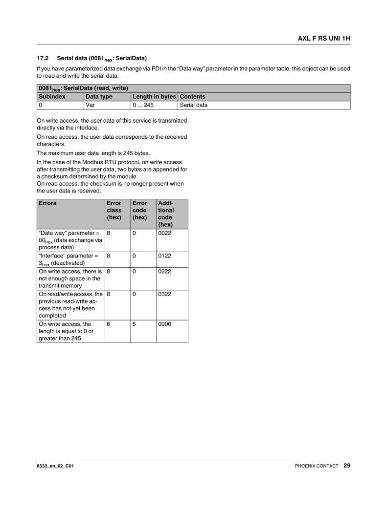
17.2 Serial data (0081hex: SerialData)
If you have parameterized data exchange via PDI in the “Data way” parameter in the parameter table, this object can be used
to read and write the serial data.
On write access, the user data of this service is transmitted
directly via the interface.
On read access, the user data corresponds to the received
characters.
The maximum user data length is 245 bytes.
In the case of the Modbus RTU protocol, on write access
after transmitting the user data, two bytes are appended for
a checksum determined by the module.
On read access, the checksum is no longer present when
the user data is received.
0081hex: SerialData (read, write)
Subindex Data type Length in bytes Contents
0 Var 0 ... 245 Serial data
Errors Error
class
(hex)
Error
code
(hex)
Addi-
tional
code
(hex)
“Data way” parameter =
00hex (data exchange via
process data)
8 0 0022
“Interface” parameter =
3hex (deactivated)
8 0 0122
On write access, there is
not enough space in the
transmit memory
8 0 0222
On read/write access, the
previous read/write ac-
cess has not yet been
completed
8 0 0322
On write access, the
length is equal to 0 or
greater than 245
6 5 0000

AXL F RS UNI 1H
8533_en_02_C01 30PHOENIX CONTACT GmbH & Co. KG • 32823 Blomberg • Germany
www.phoenixcontact.com
17.3 Event counter (0095hex: EventCounter)
You can read multiple counters which are used for interface
diagnostics with this object.
18 Device descriptions
The device is described in the device description files.
The device descriptions for controllers from Phoenix Con-
tact are included in PC Worx and the corresponding service
packs.
The device description files for other systems are available
for download at phoenixcontact.net/download in the down-
load area of the bus coupler used.
0095hex: EventCounter (read)
Subindex Data type Length in
bytes
0 Octet string 12
Word Meaning
1 Number of valid characters received
2 Number of invalid characters received (par-
ity, overrun or framing errors)
3 Number of characters transmitted
4 ... 6 Reserved