az4290 terxon 2way module gb instructions...
TRANSCRIPT

27
AZ4290
Terxon 2WAY Funkmodul Installations- und Bedienungsanleitung (DE) ................... 1
Terxon 2WAY module Installation and operating instructions (GB) ................... 27
Module Terxon 2WAY Instructions d’installation et de commande (FR)............ 53
Terxon 2WAY modulo Istruzioni di installazione e per l’uso (IT) ........................ 79
Terxon 2WAY module Installatie- en bedieningshandleiding (NL) ................... 105
Terxon 2WAY modul Installations- og betjeningsvejledning (DK) .................. 131
BOM – No.: 11877626
28
Contents 1. Preface ........................................................................................................................ 29 2. Conformity .................................................................................................................... 29 3. Meaning of the symbols ............................................................................................... 30 4. Safety information ........................................................................................................ 30 5. Scope of delivery ......................................................................................................... 30 6. Features ....................................................................................................................... 31 7. Structure, control elements, display elements and connections ................................... 32 8. Quick guide .................................................................................................................. 41 9. Installation .................................................................................................................... 42 10. Programming ............................................................................................................. 43 11. Operation ................................................................................................................... 47 12. Switching example using Terxon MX ......................................................................... 48 13. Technical data ............................................................................................................ 50 14. Customer service and support ................................................................................... 51
29
1. Preface Dear customers, Thank you for purchasing the Terxon 2WAY Terxon wireless module for your alarm system. This product is built according to state-of-the-art technology. It complies with current domestic and European regulations. Conformity has been proven, and all related certifications are available from the manufacturer on request (www.abus-sc.com). To maintain this status and to guarantee safe operation, it is your obligation to observe these instructions. If you have any questions, please contact your local specialist dealer. No part of the product may be changed or modified in any way. This document relates to software release V0.7 of the Terxon 2WAY wireless module AZ4290. This manual contains important installation and operation instructions. Store these instructions in a safe place for future reference. These instructions are part of the product. Bear this in mind if you pass the product on to others. Everything possible has been done to ensure that the contents of these instructions are correct. However, neither the author nor ABUS Security-Center GmbH & Co. KG can be held liable for loss or damages caused directly or indirectly by these instructions, whether real or alleged. We reserve the right to make changes to these instructions without prior notice. © ABUS Security-Center GmbH & Co. KG, 04 / 2009 2. Conformity This product complies with the requirements of the relevant regulations of EC directive R&TTE 1999/5/EC of the European Parliament and the directive of March 9, 1999 regarding wireless systems and telecommunication transmitters and the mutual recognition of their conformity. The declaration of conformity can be ordered from: ABUS Security-Center GmbH & Co. KG Linker Kreuthweg 5 86444 Affing GERMANY www.abus-sc.com [email protected]

30
3. Meaning of the symbols Disposal as per directive WEEE 2002/96 EC
At the end of its useful life, dispose of the product according to the applicable legal requirements. Within the EU, the product and its accessories must be collected and disposed of separately. Devices that have been marked accordingly may not be disposed of as domestic waste. Please contact your dealer or dispose of the products at the local collection point for electronic waste.
This symbol indicates important notes in these operating instructions, which must be observed.
You see this symbol when there are special tips and notes on the operation of the unit.
4. Safety information This device uses Safety Extra Low Voltage (SELV). The circuits of the zones, the circuits of the switch outputs and the 12 V power supply of the Terxon alarm centres also fall into this voltage range. SELV is a low electrical current that, based on its low level and insulation compared to higher voltage circuits, offers special protection against electric shocks. 5. Scope of delivery Terxon 2WAY wireless module AZ4290 Installation and operating instructions Installation material (3 wall plugs, 3 screws)

31
6. Features The Terxon 2WAY wireless module is a bidirectional wireless enhancement module for wired alarm systems. It enables you to combine wired alarm centres from any manufacturer with bidirectional Secvest 2WAY wireless components (transducer and activation equipment of the Secvest 2WAY wireless alarm system). Since the Terxon 2WAY wireless module has relay outputs and voltage-controlled inputs, it can be integrated not just into the Terxon series but into almost any wired alarm system. The following Secvest 2WAY components can be integrated using the Terxon 2WAY wireless module: Secvest 2WAY wireless outdoor sounder FU8220 Secvest wireless indoor sounder FU8230 Wireless remote control 2WAY FU8100 Wireless control unit 2WAY FU8110 Secvest key FU59xx The Terxon 2WAY wireless module offers up to 8 channels for Secvest 2WAY components. The following table provides an overview of the respective possible maximum number of 2WAY components that you can integrate into your wired alarm system with this module. Article no. Type Maximum number FU8220 Secvest 2WAY wireless outdoor
sounder 2
FU8230 Secvest wireless indoor sounder ∞ FU8100 Wireless remote control 2WAY 8 FU8110 Wireless control unit 2WAY 8
(8 PIN/proximity chip key for wireless control units)
FU59xx Secvest key 2WAY wireless cylinder
8
The module has:
• 6 switch outputs for controlling the alarm centre. These outputs are wired to zones or inputs of the alarm centre. These outputs forward the commands from the components received via wireless to the alarm centre.
• 10 inputs for controlling the Secvest 2WAY system components. These inputs are connected to the outputs of the alarm centre. The status and control information output by the alarm centre outputs are forwarded to these inputs and then transmitted via wireless to the 2WAY system components.
• 10 LEDs for visual signalling during programming and operation. • 3 programming keys
The information that is transmitted between the Secvest 2WAY system components and the alarm centre via the Terxon 2WAY wireless module depends on the functional scope of the alarm centre. If the outputs of your alarm centre cannot be programmed to provide the output of specific status information, it will naturally not be possible to transmit this information to the 2WAY system components. It is therefore important to check every alarm centre to see whether it is suitable for communicating with the required 2WAY system components prior to installation. The Terxon 2WAY wireless module monitors the trained components (supervision). The Terxon 2WAY wireless module AZ4290 can also detect jamming independently. The Terxon 2WAY wireless module is protected against code tampering. If you enter a wrong PIN four times within 60 seconds, or if you use four impermissible proximity chip keys, the Terxon 2WAY wireless module locks itself for 90 seconds. Exception: If the “BELL” or “FIRE” input is triggered at the same time, this lock has no effect.

32
7. Structure, control elements, display elements and connections
Description:
1. Programming keys 2. Lid – tamper switch 3. Jumper for the wall tamper switch 4. Terminal block for outputs 5. Terminal block for inputs 6. Jumper for pull-up + / pull-down- resistance on the inputs 7. Jumper for INSTALLER MODE 8. Signaller 9. DIP switches 10. Setup socket (not in use) 11. LED display 12. Fixing screw
1
2
4
3
5
11
7
6
8
9 10
SK1
12
x

33
Micro controller switch The Terxon 2WAY wireless module is based on a PIC micro controller by Microchip. HF transceiver and antenna The Terxon 2WAY wireless module has an 868.6625 MHz narrow-band transceiver and a PCB antenna with diversity function. Internal Piezo signaller (8) A small Piezo signaller is installed. It outputs an acoustic signal indicating whether a component has been trained successfully and signalises statuses in setup mode. Power supply The power supply is connected to the 2 left connections labelled “+12 V / 0 V IN” on the upper terminal block. Please ensure that the polarity is correct. The Terxon 2WAY wireless module is protected against incorrect connection and therefore destruction by a pole protection diode. To ensure emergency power operation, we recommend using the alarm centre for the Terxon 2WAY wireless module power supply. Please take into account the maximum load of the external power connection of your alarm centre! The Terxon 2WAY wireless module requires a maximum of 300 mA. If additional components are connected, the total required power must not exceed the maximum load.
If you are not using the alarm centre’s power supply but a separate PSU for the Terxon 2WAY wireless module, please take the following into account:
- Connect the earth connection of the Terxon 2WAY wireless module (0 V IN) to the earth connection (0 V) of the alarm centre. This ensures that all voltages in the system refer to a joint earth potential.
- If the input voltage is missing on the Terxon 2WAY wireless module, all outputs are open. This can cause undefined statuses in your alarm system. Hence, make sure that emergency power supply is available.
______________________________________________________________________________ Display LEDs (11) The display consists of 10 LEDs ~ Green LED (“Power” LED) for monitoring the power supply
Red LED (“Trouble” LED) for displaying faults 1- 8 Blue LEDs (“Channel” LEDs) for channel display Programming keys (1) On the right, there are three keys (SELECT, SET, ESC/DEL) for programming the Terxon 2WAY wireless module.
~
8 7 6 5 4 3 2 1

34
Tamper switch A cover tamper switch (2) and a wall tamper switch protect the Terxon 2WAY wireless module against unauthorised opening and removal from the wall. The tamper information is forwarded via the tamper output (TAMP) to the alarm centre. 3-pole jumper connection CON2 “ +/- VSEL” (6) The Terxon 2WAY wireless module has internal “pull-up” and “pull-down” resistors. Open inputs therefore have defined potentials. This avoids interference due to coupling. You therefore do not need external “pull-up” or “pull-down” resistors.
If the jumper is set to the “-” position every input is set to 0 V potential (potential on “0 V IN”). If the jumper is set to the “+” position every input is set to +12 V potential (potential on “12 V IN”). CON3 jumper connection “INSTALLER MODE” (7) Secvest 2WAY wireless outdoor sounder FU8220 has a setup mode, i.e. you can open the 2WAY wireless outdoor sounder and carry out maintenance without interference and without the tamper siren being activated. The Terxon 2WAY wireless module usually sends the Secvest 2WAY wireless outdoor sounder a signal for activating setup mode if the “TEST” input is triggered.
If your alarm centre does not have a corresponding “Access setup mode” output type, you can set this jumper on both contacts so that the Terxon 2WAY wireless module sends a signal for accessing setup mode to the Secvest 2WAY wireless outdoor sounder. Make sure you also set the alarm centre to setup mode before you perform maintenance.
CON1 jumper connection “FIT DISABLE TAMP” (3) If you set the jumper on both contacts, you deactivate the wall removal contact.
DIP switch “SW6” (9) The individual switches of the 8-position DIP enable you to choose from the following options:
Switch Options “OFF” position “ON” position 1 Supervision Off On 2 Supervision time Long
3 h Short 20 min
3 Jamming detection Off On 4 Status polarity for inputs (global) High Low 5 Status for outputs (global) NC NO 6 LED mode Device PIN/proximity chip key 7 Feedback from alarm centre Yes No 8 Output response (global) Permanent Impulse

35
DIP switch 1 “Supervision” Supervision means monitoring. If you want to monitor whether the wireless components are present or active, set DIP switch 1 to On. If no status messages are received from the wireless components, output “S-FAIL” is then activated accordingly. DIP switch 2 “Supervision time” You use this switch to choose how long there can be no status messages from the wireless components before the “S-FAIL” output is activated. DIP switch 3 “Jamming detection” Jamming means wireless jamming. The 2WAY wireless module detects jamming when there is an external signal of the same frequency as the radio components that is strong enough to interfere with the radio signal of the components for at least 30 seconds a minute. If such a malfunction occurs and DIP switch 3 is set to On, output “S-FAIL” is activated. DIP switch 4 “Status polarity for inputs” You use this switch to determine the polarity of the control signal on the input for activating a function. High for +12 V, Low for 0 V The setting applies globally for all 10 inputs. DIP switch 5 “Status for outputs” You use this status to determine the switch response of the outputs. OFF for NC (normally closed) means that the switch of the output is closed when inactive. The switch of the output opens if the output is activated. ON for NO (normally open) means that the switch of the output is open when inactive. The switch of the output closes if the output is activated. The setting applies globally for all 6 outputs. DIP switch 6 “LED mode” You can use this switch to choose whether operating elements or users who control the system using the Terxon 2WAY wireless module are displayed via the LEDs. In the OFF setting, the operating element on which the system was last activated or deactivated is displayed. Operating elements are “Wireless remote control 2WAY”, “Wireless control unit 2WAY” or “Secvest Key 2WAY wireless cylinder”. The LED of the respective channel lights up. In the ON setting, the user who last activated or deactivated the system is displayed. Users are represented by codes or proximity chip keys. The LED of the respective channel lights up. For example, a proximity chip key is trained on channel 1. If it is used on any trained wireless control unit 2WAY, LED 1 lights up. In systems that contain a mixture of wireless control units 2WAY, wireless remote control 2WAY and Secvest Key 2WAY wireless cylinders, we recommend setting switch 6 to Off.

36
DIP switch 7 “Feedback from alarm centre” You can use this switch to choose whether or not the alarm centre is supposed to use its outputs to transmit its status (activated, deactivated) to the Terxon 2WAY wireless module. If the alarm centre does not have a corresponding output type that outputs its status (activated, deactivated), set the switch to ON. The Terxon 2WAY wireless module then transmits the status of its own outputs (SET-CMD, PSET-CMD) back to wireless remote control 2WAY, to wireless control unit 2WAY and to the Secvest Key 2WAY wireless cylinder. With switch 7 OFF, the Terxon 2WAY wireless module transmits the current status of the inputs “SET STATE” and “PSET STATE” to the operating elements.
You may not set both switch 7 and switch 8 to ON. If the response of the outputs of the Terxon 2WAY wireless module is set to impulse (switch 8 ON), feedback from the alarm centre is required.
In systems in which activation or deactivation is possible without using the Terxon 2WAY wireless module (e.g. on wired (bus) operating elements of the alarm centre), switch 7 must be set to OFF, and the feedback from the alarm centre as to whether it is activated or deactivated must be available. DIP switch 8 “Output response” You use this switch to specify whether, when activated, the outputs hold their status permanently or activate an impulse. Status inputs 10 status inputs on a terminal block. These status inputs are wired to the corresponding outputs of the alarm centre as required. The status inputs should be triggered by an open collector or an potential-free relay contact. The inputs can be triggered by activating or deactivating 0 V or +12 V, depending on the setting of DIP switch 4 for the global input polarity and the setting of the jumper on “CON2” +- VSEL for the global status of the inputs. Note: If you have an open collector NPN transistor on the output of your alarm centre, set the jumper for CON 2 VSEL to “+” (left and centre contacts). If its basis is activated, the collector of this output transistor switches against ground (0 V). If you have an open collector PPN transistor on the output of your alarm centre, set the jumper for CON 2 VSEL to “-” (centre and right contacts). If its basis is activated, the collector of this output transistor switches against plus. Now set DIP switch 4 in such a way that the input of the Terxon 2WAY wireless module is activated either by applying or removing high or low potential. The inputs could also be triggered with an active output where the potential fluctuates between 0 V and +12 V. On this subject, please take into account the applicable level limits in the “Technical data” section. If necessary, it is possible to control several Terxon 2WAY wireless module (parallel switched) inputs with one output of the alarm centre. On the Terxon 2WAY wireless module, the following special status inputs are available. All inputs should be assigned permanent signal values that reflect the status of the alarm centre and not with short-term impulses.

37
SET STATE This input should be triggered if the alarm centre is fully activated. You then get a message on the respective wireless components. For the actual display or signalling, please refer to the instructions of the respective wireless component. PSET STATE This input should be triggered if the alarm centre is partially activated. You then get a message on the respective wireless components. For the actual display or signalling, please refer to the instructions of the respective wireless component.
Note on SET STATE and PSET STATE: When you program the output/input mode of the alarm centre, keep in mind that the wireless remote control 2WAY FU8100 has a receipt time of approx. 10 seconds and the wireless control unit 2WAY approx. 130 seconds. If you choose longer times, you might have to use the respective query key “?” in order to be informed of the current status of your alarm centre on these operating elements.
FLT This input should be triggered if the alarm centre is not ready for activation or a general fault has occurred. You then get a message on the respective wireless components. For the actual display or signalling, please refer to the instructions of the respective wireless component. STRB This input should be triggered if the strobe light of the Secvest 2WAY wireless outdoor sounder is to be activated. Please also use this input if the activation confirmation is supposed to be signalled using the strobe light. BELL This input should be triggered if the Secvest 2WAY wireless outdoor sounder and the Secvest wireless indoor sounder are supposed to output the normal alarm sound (the normal alarm sounds if the “Bell” and “Fire” inputs are triggered at the same time). TEST This input should be triggered if the alarm centre is in setup mode. Secvest 2WAY wireless outdoor sounder FU8220 has a setup mode, i.e. you can open the 2WAY wireless outdoor sounder without the siren being activated due to tampering. The Terxon 2WAY wireless module sends the Secvest 2WAY wireless outdoor sounder a signal for activating setup mode if the “TEST” input is triggered. If your alarm centre does not have a corresponding “Access setup mode” output type, you can set this jumper on both contacts on the “CON3 INSTALLER MODE” jumper connections so that the Terxon 2WAY wireless module sends a signal for accessing setup mode to the Secvest 2WAY wireless outdoor sounder. FIRE This input should be triggered if the Secvest 2WAY wireless outdoor sounder and the Secvest wireless indoor sounder are supposed to output the fire alarm sound (the normal alarm sounds if the “Bell” and “Fire” inputs are triggered at the same time). ENTRY This input should be triggered if the Secvest wireless indoor sounder is supposed to output the “Entry delay time running” sound. For some alarm centres, you might have to summarise the inputs Entry, Exit and Exit fault and set them together on an output of the alarm centre of the type “Input/output follows”. For combinations with “Exit” and/or “Exit Fault”, the “Entry delay time running” signal is output. EXIT This input should be triggered if the Secvest wireless indoor sounder is supposed to output the “Exit delay time running” sound. For combinations with “Exit Fault”, the “Exit delay time running” signal is output.
38
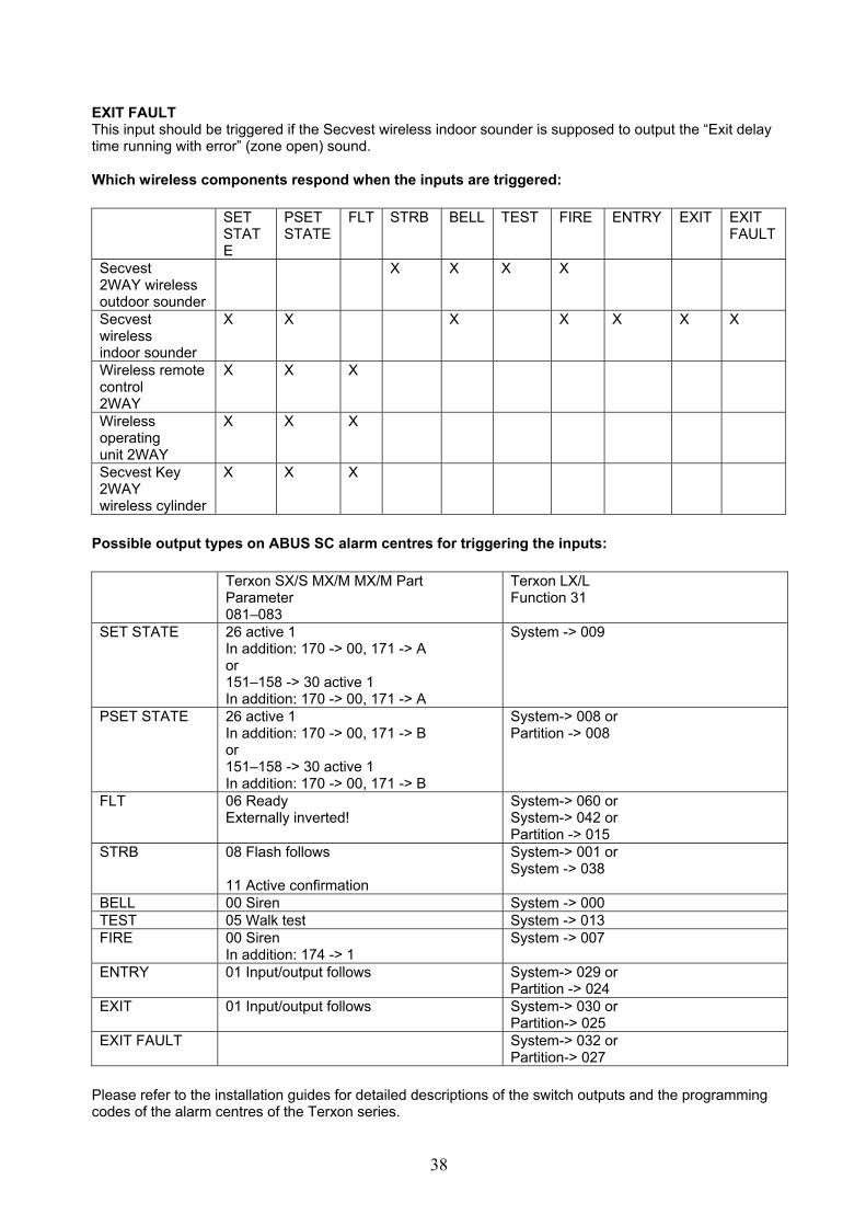
EXIT FAULT This input should be triggered if the Secvest wireless indoor sounder is supposed to output the “Exit delay time running with error” (zone open) sound. Which wireless components respond when the inputs are triggered: SET
STATE
PSET STATE
FLT STRB BELL TEST FIRE ENTRY EXIT EXIT FAULT
Secvest 2WAY wireless outdoor sounder
X X X X
Secvest wireless indoor sounder
X X X X X X X
Wireless remote control 2WAY
X X X
Wireless operating unit 2WAY
X X X
Secvest Key 2WAY wireless cylinder
X X X
Possible output types on ABUS SC alarm centres for triggering the inputs: Terxon SX/S MX/M MX/M Part
Parameter 081–083
Terxon LX/L Function 31
SET STATE 26 active 1 In addition: 170 -> 00, 171 -> A or 151–158 -> 30 active 1 In addition: 170 -> 00, 171 -> A
System -> 009
PSET STATE 26 active 1 In addition: 170 -> 00, 171 -> B or 151–158 -> 30 active 1 In addition: 170 -> 00, 171 -> B
System-> 008 or Partition -> 008
FLT 06 Ready Externally inverted!
System-> 060 or System-> 042 or Partition -> 015
STRB 08 Flash follows 11 Active confirmation
System-> 001 or System -> 038
BELL 00 Siren System -> 000 TEST 05 Walk test System -> 013 FIRE 00 Siren
In addition: 174 -> 1 System -> 007
ENTRY 01 Input/output follows System-> 029 or Partition -> 024
EXIT 01 Input/output follows System-> 030 or Partition-> 025
EXIT FAULT System-> 032 or Partition-> 027
Please refer to the installation guides for detailed descriptions of the switch outputs and the programming codes of the alarm centres of the Terxon series.

39
Status outputs 6 semi-conductor relays form the 6 outputs. The switch contacts of the relays are wired to the lower terminal block. You wire the zone inputs of the alarm centre to this terminal block. All the outputs together can either act as NC (open) or NO (close) contacts. To choose NC or NO contact, use DIP switch 5 (OFF=NC, ON=NO). Note that you cannot create a mixture of NC and NO contacts. You can connect several Terxon 2WAY wireless module outputs to a single zone input of an alarm centre. In doing so, please note: If you want the outputs to have an “OR” functionality, you have to switch NC contacts in a row and NO contacts in parallel. The Terxon 2WAY wireless module supports the connection of the subsequently described special status outputs to suitable zones of the alarm centre. You use DIP switch 8 to choose whether the outputs, when triggered, retain their status permanently or switch it as an impulse. (OFF=permanent, ON=impulse) TAMP (Tamper) The output is activated if the wall or cover tamper switch of the Terxon 2WAY wireless module has been triggered (the Terxon 2WAY wireless module has been tampered with) or a trained component has been tampered with. PANIC The output is activated if the Terxon 2WAY wireless module has received a panic signal from a trained wireless remote control 2WAY. SET-CMD (SET-COMMAND) The output is activated if the Terxon 2WAY wireless module has received an activation signal from a trained component. The output is usually connected to a key switch zone of the alarm centre. You can use zone types “Key switch impulse” or “Key switch permanent” (key switch). However, keep in mind the setting of DIP switch 8 and the corresponding explanations. PSET-CMD (PART SET-COMMAND) The output is activated if the Terxon 2WAY wireless module has received an internal activation signal from a trained component. The output is usually connected to a key switch zone of the alarm centre. You can use zone types “Key switch impulse” or “Key switch permanent” (key switch). However, keep in mind the setting of DIP switch 8 and the corresponding explanations.
Note for SET-CMD and PSET-CMD: If you want to use both outputs, i.e. activate the alarm system completely on the one hand, or, on the other hand, only activate the alarm system in parts, you need corresponding types of outputs on the alarm centre that switch permanently (not as an impulse) and only for the respective state. The output on the alarm centre that signals the complete activation of the system must not switch if only part of the system is activated.
LBATT (LOW BATTERY) The output is activated if the trained wireless component reports a “low battery”. S-FAIL (SUPERVISION OR JAMMING FAIL) The output is activated if the Terxon 2WAY wireless module has lost wireless contact with a trained component. This is triggered either due to jamming or a general supervision failure. Additional information is signalled on the LEDs; refer to the “LED displays during operation” section.

40
Which trained component can switch which output: TAMP PANIC SET-CMD PSET-CMD LBATT S-FAIL Secvest 2WAY wireless outdoor sounder FU8220
X X X
Secvest wireless indoor sounder FU8230
Wireless remote control 2WAY FU8100
X X X X
Wireless control unit 2WAY FU8110
X X X X
Secvest key 2WAY wireless cylinder FU59xx
X X X X X
Possible zone types on ABUS SC alarm centres that can be controlled by the outputs of the Terxon 2WAY wireless module. Terxon SX/S MX/M MX/M Part
Terxon LX
TAMP Tamper line Com A/T
All zones Code 12 tamper
PANIC All zones Code 01, PA – Panic
All zones Code 03 Panic silent or Code 04 Panic loud
SET-CMD All zones Code 12, KF – Key switch stable
All zones Code 10 Key switch (permanent)
PSET-CMD All zones Code 12, KF – Key switch stable with addition A, B, C or D
All zones Code 10 Key switch (permanent) and partition
LBATT All zones Code 08, TC – Technology zone
All zones Code 15 Battery
S-FAIL All zones Code 08, TC – Technology zone
All zones Code 06, Technology
41
8. Quick guide Plan which wireless components you wish to use and how many of them. You can use a maximum of 8 channels. Draw up an installation plan. Be aware of how many wire outputs you can use on your alarm centre and which output types you can set. Determine the type of outputs (transistor output as open collector or relay) and the switch response of the outputs. Does the transistor output switch against plus or ground if it is activated by the alarm centre? Does the relay output work as an opener or closer if it is activated by the alarm centre? Be aware of how many zones of the alarm centre you can use and which zone types you can set. Take into account the wiring of the zones (Normally Open, Normally Closed, Closed Circuit, End of Line, Double End of Line). Test the wireless reception at the installation location of the Terxon 2WAY wireless module. To do so, you can use the actual module (menu 4 – Display signal strength). To test the wireless reception at the installation location of the Terxon 2WAY wireless module and at the installation locations of the wireless components, you can also use wireless test box FU3801. To do so, place the wireless test box at the possible installation location of the Terxon 2WAY wireless module. Trigger a transmission by the wireless components. On the Secvest 2WAY outdoor sounder, activate the tamper switch. In order for the wireless remote control 2WAY, the wireless operating unit 2WAY and the Secvest Key 2WAY wireless cylinder to send a signal, activate these wireless components. In the next steps, place the wireless test box at the possible mounting locations of the wireless components. Trigger a transmission by the Terxon 2WAY wireless module by triggering an input. The test is easier if, instead of the Terxon 2WAY wireless module, you use a wireless component, e.g. the wireless operating unit 2WAY, for sending a signal. Install the Terxon 2WAY wireless module so that the terminal blocks are on the bottom. Wire the Terxon 2WAY wireless module with the alarm centre. You should do this whilst the alarm centre and the Terxon 2WAY wireless module are switched off. Set the jumper for “CON1 FIT DISABLE REAR TAMPER” as desired. Set the jumper for “CON2 + VSEL” as required. Set the jumper for “CON3 INSTALLER MODE” to one contact only. Set all DIP switches to the desired position. Program the Terxon 2WAY wireless module, train the wireless components and, if appropriate, train the desired PIN/proximity chip keys. Test whether it works as desired. Close the housing.
42
9. Installation
A. Wall tamper switch B. Display C. Fixing screw D. Terminal block E. Mounting holes on bottom plate F. Cable bushing
1. Loosen the fixing screw on the bottom narrow side and open the housing. 2. Remove fixing screw (C) that is above the LED board. 3. Pull the PCB carefully upwards and out. 4. Using the back of the housing as a template, mark the drill holes (E). Drill the holes for the
fixing screws. 5. Guide the connection cable through the appropriate opening (F). 6. Fix the housing to the wall. 7. Fit the PCB and make sure the spring of the wall tamper switch (A) is placed correctly. Affix the
fixing screw (C) that is above the LED board again. 8. Correctly connect the power supply to terminal block (D). The terminal block is labelled accordingly.
Connect the wires of the connection cable leading to the alarm centre according to the wiring plan to terminal blocks (D). Make sure that stripped parts of wires of the cable that are not used do not touch the PCB.
9. After programming and start-up, replace the lid and tighten the lid screw.
B E
F
E E
CD
A

43
10. Programming Activation Connect the power supply (12 V). The two connector clamps on the far left are marked with 12 V for plus and 0 V for minus. The Terxon 2WAY wireless module beeps twice and the top LED (green) lights up. Programming Press SELECT once to go to programming mode. You are then in the main menu. The lowest LED lights up for menu 1. Pressing SELECT again lets you choose the following 5 menu items. The corresponding LED lights up. Press SET once to get to the menu and the LED switches off or flashes according to the individual menus. (The exception is menu 8, where all LEDs flash.) Always close programming mode as described below to ensure that the new settings are saved. Please do not simply disconnect the power supply. Press ESC/DEL until the Terxon 2WAY wireless module starts beeping (about once per second). Close the Terxon 2WAY wireless module housing and hold the lid tamper contact SW4 down for about 4 seconds until it beeps twice.
If the Terxon 2WAY wireless module has not been mounted to the wall yet, please keep in mind that the wall tamper switch must also be pressed or deactivated by the “FIT DISABLE TAMP” jumper.
All programmed settings and the data of the trained components are saved in an EEPROM. This data is not lost in case of a power failure. Menu 1 – Training the components Press SELECT (top right) once to go to programming mode. The bottom LED (blue) lights up. You are then in the main menu. Press SET once to go to menu 1. The bottom LED switches off. Trigger the sending of a wireless signal from the components to be trained. To train a Secvest 2WAY wireless outdoor sounder, a wireless operating unit 2WAY or a Secvest Key 2WAY, activate the respective tamper contact(s). To train a WIRELESS REMOTE CONTROL 2WAY, press any button. Once the first component is trained, the Terxon 2WAY wireless module beeps twice and the LED of the first channel flashes. Repeat this operation for additional components. This assigns additional channels. Note that a maximum of 8 channels can be assigned. Once you’re done, press ESC/DEL once. At this point, the Terxon 2WAY wireless module does not let you press any other buttons. The bottom LED lights up again permanently. You are in the main menu again. If you want to close programming mode, press ESC/DEL until the Terxon 2WAY wireless module starts beeping (about once per second). Close the Terxon 2WAY wireless module housing and hold the lid tamper contact (SW4 underneath ESC/DEL) down for about 4 seconds until it beeps twice. The data is saved in an EEPROM.

44
Menu 2 – Deleting the components Press SELECT until the second LED from the bottom lights up. Press SET once to go to menu 2. The LED of a channel with a trained component starts flashing. Press SELECT again until the desired channel flashes. Empty channels cannot be selected. If the LED of the desired channel flashes, press (beeps once) and hold ESC/DEL (about 4 seconds) until the Terxon 2WAY wireless module beeps twice and LED 2 lights up again. The component has been deleted. You are now automatically back in the main menu. If necessary press SET to get back to menu 2, and repeat the process described above. If you want to close programming mode, press ESC/DEL until the Terxon 2WAY wireless module starts beeping (about once per second). Close the Terxon 2WAY wireless module housing and hold the lid tamper contact (SW4 underneath ESC/DEL) down for about 4 seconds until it beeps twice. The data is saved in an EEPROM. Menu 3 – Train PIN / proximity chip key Press SELECT until the 3rd LED from the bottom lights up. Press SET once to go to menu 3. To train a PIN or proximity chip keys, use a wireless operating unit 2WAY, which you previously trained as per menu 1. Please note that the wireless operating unit 2WAY must be supplied with 12 volt external voltage so that you can use a proximity chip key. Enter the desired 4-digit code/PIN and choose ACTIVATE ALL. Once the first code/PIN is trained, the Terxon 2WAY wireless module beeps twice, occupies the first PIN/proximity chip key position and the LED of the first channel flashes. Or you move the proximity chip key in front of the wireless operating unit 2WAY until the wireless operating unit 2WAY beeps and then press the ACTIVATE ALL key. Once the first proximity chip key is trained, the Terxon 2WAY wireless module beeps twice, occupies the first PIN/ proximity chip key position and the LED of the first channel flashes. Repeat the operation for additional PINs or proximity chip keys. This assigns additional channels. Note that a maximum of 8 channels can be assigned. Once you’re done, press ESC/DEL once to get back to the main menu. If you want to close programming mode, press ESC/DEL until the Terxon 2WAY wireless module starts beeping (about once per second). Close the Terxon 2WAY wireless module housing and hold the lid tamper contact (SW4 underneath ESC/DEL) down for about 4 seconds until it beeps twice. The data is saved in an EEPROM.
Note! The software does not allow you to delete individual PINs or proximity chip keys. To delete PINs or proximity chip keys, close the menu 8 factory setting. If you do this, all PIN/proximity chip keys and all components are deleted.
45
Menu 4 – Display of the signal strength Press SELECT until the 4th LED from the bottom lights up. Press SET once to go to menu 4. The LEDs then display the last received signal strength for every channel. This happens as follows: First, a channel LED flashes for 3 seconds and then the signal strength is displayed as a bar between 0 and 9. The corresponding number of LEDs (starting from the bottom) light up. The Terxon 2WAY wireless module automatically goes through 8 channels. If no wireless components are trained, you cannot choose this submenu. The LEDs show the strength of the received signal. The more LEDs light up (from bottom to top), the stronger the signal. If only two or fewer LEDs light up, the signal is not strong enough for reliable operation.
The display of the last received signal strength of the channels can be reset by pressing the ESC button. However, you are in the main menu again. LED 4 lights up again. If you press the SET button again, all signal strengths are deleted and you can start afresh.
Components can be triggered during the test. The display of the last received signal strength is updated. Once you’re done, press ESC/DEL once to get back to the main menu. If you want to close programming mode, press ESC/DEL until the Terxon 2WAY wireless module starts beeping (about once per second). Close the Terxon 2WAY wireless module housing and hold the lid tamper contact (SW4 underneath ESC/DEL) down for about 4 seconds until it beeps twice. The data is saved in an EEPROM. Menu 5 – Enabling the triggering of the Secvest wireless indoor sounder and training the Terxon 2WAY wireless module in a Secvest wireless indoor sounder Press SELECT until the fifth LED from the bottom lights up. Press SET once to go to menu 5. Take a look at the status of the 5th LED. If it does not flash, the sending of a message to the Secvest wireless indoor sounder is not activated. If the LED flashes, the Terxon 2WAY wireless module is ready to send a message to the Secvest wireless indoor sounder. If necessary, change this status by pressing the SET button again. As soon as the Terxon 2WAY wireless module is in the desired status (LED flashing or off) press ESC/DEL once to return to the main menu. The Terxon 2WAY wireless module can be trained in a Secvest wireless indoor sounder as soon as you leave programming mode.

46
Training the Terxon 2WAY wireless module in a Secvest wireless indoor sounder To train the Terxon 2WAY wireless module in a Secvest wireless indoor sounder, the Terxon 2WAY wireless module must be ready to send a message to the Secvest wireless indoor sounder. (As described in the preceding section). Now leave programming mode. Press ESC/DEL until the Terxon 2WAY wireless module starts beeping about once per second. Close and hold the lid tamper contact (SW4 underneath ESC/DEL) down for about 4 seconds until it beeps twice. The data is saved in an EEPROM. Once you have done this, press SET to send the training signal to the Secvest wireless indoor sounder(s). To train the Terxon 2WAY wireless module in several Secvest wireless indoor sounders in a row, press the set button again each time.
Make sure that the Secvest wireless indoor sounder is activated, i.e. that a power supply (battery and/or external power supply) is connected to the Secvest wireless indoor sounder and the “Learn” jumper is set across both contacts. Remove this jumper after training. Set the jumper for selecting the partition. It does not matter which partition is selected, but a partition must be selected. The Secvest wireless indoor sounder will always respond then. Menu 6 – not in use Menu 7 – not in use Menu 8 – Set default factory settings Press SELECT until the 8th LED from the bottom lights up. Push the SET button once to get to menu 8. All blue LEDs start flashing. This display signals that the Terxon 2WAY wireless module is ready to reset itself to the factory settings. Push and hold the ESC/DEL button for about 4 seconds until the flashing stops and the Terxon 2WAY wireless module beeps twice. The factory settings are now loaded again. You are now back in the main menu. If you want to close programming mode, press ESC/DEL until the Terxon 2WAY wireless module starts beeping (about once per second). Close the Terxon 2WAY wireless module housing and hold the lid tamper contact (SW4 underneath ESC/DEL) down for about 4 seconds until it beeps twice. The data is saved in an EEPROM.

47
11. Operation LED displays
The green “Power” LED is illuminated permanently if the power supply is connected and active.
The LED is often the only indication that the device is switched on.
The red “Trouble” LED is usually off. If the Terxon 2WAY wireless module detects a supervision failure, it flashes with 1 Hz and the corresponding channel LED of the trained component also flashes with 1 Hz. If the Terxon 2WAY wireless module detects jamming, the LED lights up permanently. The display for jamming takes precedence over the display of a supervision failure. Channel LEDs The display of the blue “channel” LEDs varies depending on the trained component on this channel. Secvest 2WAY wireless outdoor sounder FU8220 • Flashing (1 Hz) The Secvest 2WAY wireless outdoor sounder FU8220 has been tampered with. If the
”Trouble” LED is also flashing, a supervision failure has occurred. • Flashing (5 Hz) The Secvest 2WAY wireless outdoor sounder FU8220 on this channel has a low battery. • Off The Secvest 2WAY wireless outdoor sounder FU8220 is in normal mode. Wireless remote control 2WAY FU8100 • Flashing (5 Hz) The wireless remote control 2WAY FU8220 on this channel has a low battery. • ON The wireless remote control 2WAY FU8220 on this channel was the last component that
sent an activation or deactivation signal. • Off Normal mode. Wireless control unit 2WAY FU8110 • Flashing (1 Hz) The wireless operating unit 2WAY FU8110 has been tampered with. • Flashing (5 Hz) The wireless operating unit 2WAY FU8110 on this channel has a low battery. • On and device mode is activated (DIP switch 6=OFF):
The wireless control unit 2WAY FU8110 on this channel was the last component that sent an activation or deactivation signal.
• On and PIN/proximity chip key mode is activated (DIP switch 6=ON): The PIN/proximity chip key assigned at this spot was the last user who triggered the sending of an activation or deactivation signal.
• Off Normal mode. Secvest Key 2WAY wireless cylinder FU59xx • Flashes (1 Hz) If the Secvest Key 2WAY wireless cylinder FU59xx sends the tamper signal. If the
”Trouble” LED is also flashing, a supervision failure has occurred. • Flashing (5 Hz) The Secvest Key 2WAY wireless cylinder FU59xx has a low battery. • On The Secvest Key 2WAY wireless cylinder FU59xx on this channel was the last
component that sent an activation or deactivation signal. • Off Normal mode.
~
8 7 6 5 4 3 2 1
~

48
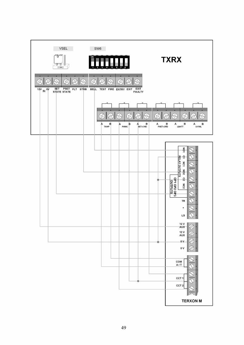
12. Switching example using Terxon MX The purpose of this sample installation is to explain the basic use of the Terxon 2WAY wireless module. First, start with the wiring, setting the jumpers and setting the DIP switches. The following graphic shows the connection and the settings. If you do not use an externally wired alarm device, you have to set the wire bridge between connections “TR” and “0 V” on the PCB of the alarm centre. Also read the basic notes on starting up the alarm centre. Now program the alarm centre. The alarm centre is to operate as a partitioned system. Menu item: 098 – Factory settings Exit mode for overall area: Menu item 039 with 3 immediately You program the zones used here as follows: Zone 1: Menu item 001 with12 KF Key switch Zone 2: Menu item 002 with 01 PA Panic You program the outputs used here as follows: Output 1: Menu item 81 with 00 Siren Output 2: Menu item 82 with 08 Flash Output 3: Menu item 83 with 26 Active 1 In addition: Menu item 170 with 00 Stable and menu item 171 with A Train your wireless components and program the Terxon 2WAY wireless module according to these instructions. This switching example can be used to integrate all 5 wireless components into the alarm system. Secvest 2WAY wireless outdoor sounder Flash and siren if alarm is activated Secvest wireless indoor sounder Siren if alarm is activated Wireless remote control 2WAY Activation and deactivation area A, panic and query of the
status of the alarm centre Wireless control unit 2WAY Activation and deactivation area A and query of the status
of the alarm centre Secvest Key Activation and deactivation area A You can operate the alarm centre using the corresponding wireless components and the wired operating units of the centre itself.
49

50
13. Technical data Security level: 2 EN 50131-1 and -3 :2007-04 Environment class: II, EN50131-1 or EN50130-5
Operating temperature: -10 °C to +55 °C, EN50130-5 Clause 8 (+55 °C) and Clause 10 (-10 °C), with average relative humidity 75%, non-condensing
Power supply: 10-14 V DC, 12 V DC nominal, device protected by pole protection diode Power consumption: max. 300 mA Emergency power supply: None Number of channels: 8 device channels
8 PIN/proximity chip key channels Display: 10 LEDs, visible from the outside when housing is closed.
8 blue LEDs for channels and programming 1 red LED for faults 1 green LED to display the power supply
Outputs: 6 semi-conductor relays with potential-free contacts (can be set to NO or NC) for
Tamper Panic Activation command Internal activation command Low battery Supervision or Jamming
Maximum switching power
U DC max = 48 V DC I DC max = 500 mA U AC max = 30 V AC rms I AC max = 350 mA rms
Forward resistance of <=2 Ω Lock resistance >=50 MΩ (at a maximum creepage of 1 µA at 50 V)
Inputs: 10, voltage-controlled, for Alarm centre activated Alarm centre internally activated Not ready for activation or general fault Flash Siren in case of alarm Setup mode Siren in case of fire Input time info beep Output time info beep Error during output time info beep

51
For each input: Max. input voltage = Vsupply (as applied on terminal block 1 terminal 1 (12 V IN)) Max. input voltage = 0 V (as applied on terminal block 1 terminal 2 (0 V IN)) VILmax (V_Input_Low_max) = 0.5 V (Low = 0 to 0.5 V), applied to terminal block 1 terminal 2 (0 V IN) VILmax (V_Input_Low_max) = 7 V (Low = 0 to 7 V), applied to terminal block 1 terminal 2 (0 V IN) Compatibility: Terxon LX AZ4200, Terxon L AZ5200,
Terxon MX AZ4100, AZ4150, Terxon M AZ5100, AZ5150 Terxon SX AZ4000, Terxon S AZ5000 as well as alarm centres from other manufacturers Secvest 2WAY wireless outdoor sounder FU8220 Secvest wireless indoor sounder FU8230 Wireless remote control 2WAY FU8100 Wireless control unit 2WAY FU8110 Secvest key 2WAY wireless cylinder FU59xx
Tamper switch Ceiling and wall Programming keys 3 (SELECT, SET, ESC/DEL) Option switch: 8 position DIP switch for
Supervision (On/Off) Supervision short/long (3 h/20 min) Jamming detection (On/Off) Status polarity for inputs (global 0 V/12 V) Status for outputs (global NC/NO) PIN/proximity chip key channels or device mode Feedback from the alarm centre, activated or internal
activated (Yes/No) Output response (Permanent/Impulse)
Dimensions: 136 x 223 x 42 mm (W x H x D) Weight: 330 g Housing material: ABS (thermoplastic) HF transceiver: Operating frequency 868.6625 MHz at 20 kHz bandwidth. I-ETS 300 220. CE-
tested as per I-ETS 300 339 (draft standard). HF transmission power: 10 mW (antenna input), PCB antenna with diversity function.
Transmission range: approx. 30 m indoors (depending on environmental factors) approx. 100 m outdoors (depending on environmental factors)
The aforementioned values are approximate. The transmission and reception ranges of the Terxon 2WAY wireless module, the operating elements and the signallers is highly dependent on the environment in which they are installed. The devices’ exact ranges can only be determined by means of on-site measurements.
14. Customer service and support End consumer: Please consult your dealer or installer if you have any questions. Dealers/installers: Consult our website for product support information:
www.abus-sc.com

52