b-gl-372-005. 35 mm twin gun gdf 005. drill book
TRANSCRIPT

OPERATION DOCUMENTATION
35 mm TWIN GUN GDF 005DRILL BOOK(ENGLISH)
(This publication becomes active on receipt.)
Issued on the authority of the Chief of the Land Staff
B-GL-372-005/FP-001
WARNINGALTHOUGH NOT CLASSIFIED, THIS PUBLICATION, OR ANY PART OF IT,MAY BE EXEMPT FROM DISCLOSURE TO THE PUBLIC UNDER THEACCESS TO INFORMATION ACT. ALL ELEMENTS OF INFORMATIONCONTAINED HEREIN MUST BE CLOSELY SCRUTINIZED TO ASCERTAINWHETHER OR NOT THE PUBLICATION OR ANY PART OF IT MAY BERELEASED.


OPERATION DOCUMENTATION
35 mm TWIN GUN GDF 005DRILL BOOK(ENGLISH)
(This publication becomes active on receipt.)
Issued on the authority of the Chief of the Land Staff
OPI: DAD 7-3 2000-06-30
B-GL-372-005/FP-001
WARNINGALTHOUGH NOT CLASSIFIED, THIS PUBLICATION, OR ANY PART OF IT,MAY BE EXEMPT FROM DISCLOSURE TO THE PUBLIC UNDER THEACCESS TO INFORMATION ACT. ALL ELEMENTS OF INFORMATIONCONTAINED HEREIN MUST BE CLOSELY SCRUTINIZED TO ASCERTAINWHETHER OR NOT THE PUBLICATION OR ANY PART OF IT MAY BERELEASED.


35 mm Twin Gun GDF 005 Drill Book
i
FOREWORD
1. B-GL-372-005/FP-001 35 mm Twin Gun GDF 005 DrillBook is issued on the authority of the Chief of the Land Staff. B-GL-372-005/FP-001 35 mm Twin Gun GDF 005 Drill Book is effectiveupon receipt.
2. The French version of this publication is B-GL-372-005/FP-002, École de la pièce du canon bitube GDF 005 de 35 mm.
3. Suggested amendments should be forwarded through normalchannels to DLAEEM 3.
4. Unless otherwise noted, masculine pronouns contained hereinrefer to both genders.
© DND/MDN 2000


35 mm Twin Gun GDF 005 Drill Book
iii
PREFACE
1. This drill book is the operator's handbook. Thus, it does notcontain a complete description of the 35 mm Twin Gun GDF 005.After completion of the operator's course, it is intended as a guidebook to be used by operators in carrying out their duties.
2. The parts of this manual follow a standard sequence, i.e.,proceed from point 1 to the last point, page for page, to complete alltasks necessary for correct gun operation. Part 2 is of centralimportance. It details drills which must always be carried out. Thedrills detailed in all other parts are only to be carried out on ordersfrom the Detachment Commander.
3. The Detachment Commander has the authority to interrupt aprocedure or change the sequences. All checks are the responsibilityof the Detachment Commander and will be carried out on his order.
4. The detachment Second in Command is responsible for theinitial defence of the gun emplacement. He works under the commandof the Detachment Commander.
5. Command and reports are written in capital letters enclosedwith quotation marks, .e.g., “ATTENTION ALIGNMENT CHECK.”Hardware lettering is written in capital letters, e.g., CONVEYORMOTOR switch is ON, etc
6. Danger, warnings and the exercise of caution are indicated bysymbols which appear in front of the text to which they refer.
7. To avoid accidents or damage to equipment during Twin GunGDF 005 operation and maintenance, always verify that the gun isunloaded and observe the following safety rules:
B-GL-372-005/FP-001
iv
SECTION 1GENERAL
CAUTION
1. Do not move the Twin Gun unless the drawbar hasbeen unlocked.
2. Do not tow away the gun until the retaining clipson the hand brake levers have been secured.
3. Do not move the gun unless the front and rearsuspension are locked.
4. Do not move the gun manually unless the rearhand brakes and the drawbar are manned.
5. Do not use a prime mover that has not beenapproved for use in moving the gun.
6. Do not tow away the gun unless the brakes and thevehicle lighting have been tested.
7. Do not back up the gun with a prime mover.
8. Do not drive over cables.
9. Do not lower levelling jacks on top of cables.
10. Do not leave the Power Supply Unit (PSU) in theupper or lower positions unless the safety pin has beeninserted in the PSU positioning mount locking lever.
11. Do not unhitch the drawbar unless the vehiclelighting cable and brake couplings have been disconnected.

35 mm Twin Gun GDF 005 Drill Book
v
DANGER
1. Do not attempt to jack up the gun unless theswivel arms are fully deployed and locked.
2. Do not operate the PSU unless the covering hoodis in place.
3. Do not move barrels unless PSU is in the loweredposition.
4. Do not operate periscope wiper in dry weather orwhen the Video Presentation Unit (VPU) is installed.
5. Do not engage the manual traverse drive unlessthe PSU is in the lower position and the barrel support hasbeen folded down.
6. Do not operate a gun unless the separatingdistance to a neighbouring gun is at least 20 metres.
7. Do not overload the automatic loader when thegun is in horizontal load position. Excess clips will fallfrom the automatic loader at high gun elevation angles.
8. Do not leave the crank handle on the automaticreloader after use.

B-GL-372-005/FP-001
vi
WARNING
1. Do not leave a stationary gun unattended on itswheels unless all four hand brakes have been applied andthe wheel chocks have been inserted.
2. Do not take up position on the sides of the guntrailer (i.e., between the wheels or between a wheel and thechassis) while the gun is being moved.
3. Do not work alone on the gun.
4. Do not work on the gun unless the fireextinguisher has been removed from the gun and placed in asafe and readily accessible location.
5. Do not open the caps on the battery cells while thePSU is running.
6. Do not refuel PSU except with refuelling system.Manual refuelling is permitted only in case of anemergency.
7. Do not place fuel cans near the PSU exhaust pipe.
8. Do not operate the gun unless the 10 metrediameter safety fence has been installed.
9. Do not approach within the safety zone of the gunwhen the traverse lock is not engaged.
10. Do not engage the elevation or traverse drivesunless it has been verified that nobody is within themovement zone of the barrels.
11. Do not step on the wheels of a gun in levelledfiring position unless the wheels have been locked.
12. Do not sit on the automatic reloaders unless theinstructor's seat has been installed.

35 mm Twin Gun GDF 005 Drill Book
vii
WARNING
1. Do not store or mix dummy rounds with liveammunition.
2. Do not initiate the quick test unless theNORMAL/TEST lever on the laser transmitter is set toTEST.
3. Do not fire the gun unless the hand ratchet hasbeen removed after manual ammunition feeding.
4. Do not participate in gun firing without wearingear protectors.
5. Do not fire a gun unless the front cover of thecradle is closed and the receivers are locked.
WARNING—MAINTENANCE
1. Do not connect or disconnect the power cablesunder voltage.
2. Do not open compartments containing electricalcomponents unless the PSU or external power source hasbeen switched off.
3. Do not remove electrostatic sensitive componentsunless the appropriate safety measures have been taken.
4. Do not work on the gun in a lightning storm.
5. Do not attempt to perform maintenance of the gununless all live ammunition has been removed.

B-GL-372-005/FP-001
viii
DANGER
1. Do not perform the functional check unless all liveammunition has been removed from the gun.
2. Do not attempt to tow the gun unless the brakerelease lever is in the FULL LOAD position.
3. Do not place hands inside the automatic loaderconveyor drive mechanism during operation unlesselectrical power has been interrupted and the spring motortension has been released.
4. Do not climb on or off the gun unless the traverselock is ENGAGED.
5. Do not attempt to remove the barrels or parts ofthe weapon unless the cradle lock has been engaged.
6. Do not attempt to clear stoppages or performautomatic loader maintenance unless the conveyor motorhas been switched off and the spring motor tension has beenreleased.
7. Do not release the breech block after firing unlessthe weapons have been cocked, the cartridge chamberchecked and the barrels have been aimed into the firingzone.
8. Do not open the weapon cover or attempt toperform corrective action for at least 20 minutes if a misfireis suspected to have occurred. A misfired round mayremain in the chamber.
35 mm Twin Gun GDF 005 Drill Book
ix
DANGER—LASER
1. The laser rangefinder operates with an invisiblebeam that is dangerous to the eyes.
2. The laser safety range is 2400 metres and appliesto the naked eye only. When binoculars or a telescope areused to observe the gun emplacement, the safety range mustbe increased by the magnifying factor of the optics.
3. Do not operate the gun in peace time unless thelaser safety plate is set to BLUE.
4. Do not direct the laser towards people, animalsand/or passing objects.
5. Do not remain within the safety range withoutsafety goggles when the laser is operating.
6. Do not operate the laser unless the laser safetysector has been programmed.
7. Do not use binoculars, telescopes or opticalmagnification aids to observe a target that is being lasered.
8. Do not look at the periscope window whentracking is in progress.
FIRST AID—ELECTRIC SHOCK
1. Switch off PSU before touching victim.
2. Remove victim from the danger zone.
3. Immediately call for medical help.
4. Start artificial respiration without delay andcontinue until medical help arrives.


35 mm Twin Gun GDF 005 Drill Book
xi
TABLE OF CONTENTS
FOREWORD .......................................................................... i
PREFACE ........................................................................iii
SECTION 1 GENERAL ............................................................ iv
CHAPTER 1 GENERAL
SECTION 1 INFORMATION FOR TRANSPORTOPERATION ......................................................... 1
SECTION 2 GUN DETACHMENT POSITIONS...................... 5
Detachment Front .................................................................... 5
Detachment Rear ..................................................................... 5
Detachment Mounted in Vehicle ............................................. 6
Detachment Front .................................................................... 7
Detachment Rear ..................................................................... 7
SECTION 3 GUN CONFIGURATION DURING OPERATION9
SECTION 4 REMOTE CONTROLLED OPERATION........... 10
SECTION 5 DUTIES OF GUN DETACHMENT.................... 10
SECTION 6 FORM DETACHMENTS FRONT (OR REAR) . 14
SECTION 7 TELL OFF............................................................ 14
SECTION 8 CHANGE ROUND .............................................. 14
SECTION 9 SAFETY............................................................... 15
Laser ...................................................................................... 15
Trigger ................................................................................... 16
Servo Sector/Fire Sector/Laser Sector/ Limited Zone ........... 17
Personnel Safety .................................................................... 18
Travelling .............................................................................. 18
Firing ..................................................................................... 19
Misfire/Stoppage Safety Procedure ....................................... 19
CHAPTER 2 STANDARD OPERATING PROCEDURES
SECTION 1 GUN PREPARATION......................................... 21

B-GL-372-005/FP-001
xii
SECTION 2 GUN PREPARATION......................................... 23
Halt—Prepare for Action....................................................... 23
Halt—Action Action Action.................................................. 26
Readiness Check.................................................................... 29
Virify Servo Sector [Menu 10] and Training Simulator 2 Mod[Menu 23] Settings ................................................................ 32
Drift Trim [Menu 1] .............................................................. 33
Set Gun Alignment [Menu 2] ................................................ 33
Set Fixed Points and Loading Position [Menu 2] .................. 36
Set Laser Sector [Menu 3] ..................................................... 37
Set Fire Sector [Menu 4] ....................................................... 38
Check Alignment [Menu 2]................................................... 39
Check Fixed Points and Loading Position [Menu 2] ............. 40
Check Laser Sector [Menu 3]................................................ 41
Check Fire Sector [Menu 4] .................................................. 42
Set Distances [Menu 5] ......................................................... 43
Enter Firing Data [Menu 6] ................................................... 45
Enter Meteorological Data [Menu 7]..................................... 46
Quick Test [Menu 8] ............................................................. 47
Error Messages [Menu 9] ...................................................... 48
Alarm Sectors ........................................................................ 48
Fire Trigger Check ................................................................ 50
Loading.................................................................................. 51
Loading: Initialise Ammunition Account .............................. 52
Unload ................................................................................... 53
Standby.................................................................................. 56
SECTION 3 GUN/FIRE UNIT INTEGRATION..................... 57
Introduction ........................................................................... 57

35 mm Twin Gun GDF 005 Drill Book
xiii
Communication, PSU Run Up and DataTransmission Check .............................................................. 58
Direct Orientation .................................................................. 59
Indirect Orientation................................................................ 61
Alignment Check................................................................... 63
Zero Test................................................................................ 64
Fictitious Target Firing.......................................................... 65
SECTION 4 TARGET ENGAGEMENT.................................. 67
Introduction ........................................................................... 67
Local Engagement with Laser Rangefinder........................... 67
Local Engagement with Fixed Distance ................................ 68
Local Take Over/Remote Acquisition ................................... 68
Local Take Over/Autonomous Acquisition ........................... 70
Local Engagement Air Targets .............................................. 71
Local Engagement Ground Targets ....................................... 73
Automatic Reloading/Refill Reloaders.................................. 75
Update Ammunition Account................................................ 76
SECTION 5 AFTER ENGAGEMENT..................................... 77
Introduction ........................................................................... 77
Prepare to Move .................................................................... 77
Cease Firing........................................................................... 78
SECTION 6 AUXILIARY OPERATION MODE.................... 81
Introduction ........................................................................... 81
Halt—Action Manual ............................................................ 81
Readiness Check—Manual.................................................... 83
Fire Trigger Check—Manual ................................................ 85
Loading—Manual.................................................................. 86
Standby—Manual .................................................................. 87
Powered with Manual Drive.................................................. 88

B-GL-372-005/FP-001
xiv
Firing with Laser ................................................................... 89
Firing with Fixed Distance .................................................... 90
Firing Without Power ............................................................ 90
Reloading—Manual .............................................................. 91
Cease Firing—Manual........................................................... 92
SECTION 7 QUICK ACTION ................................................. 94
Introduction ........................................................................... 94
Quick Action, Electrically Supported.................................... 94
Manual Quick Action ............................................................ 96
SECTION 8 PREPARE GUN FOR TRAININGSIMULATOR 2.................................................... 98
CHAPTER 3 RANGE OPERATIONS
SECTION 1 RANGE FIRING................................................ 101
Introduction ......................................................................... 101
Systematic Sequence for Preparation of the Fire Unit......... 102
SECTION 2 DUTIES OF NUMBER 1................................... 103
Before Firing ....................................................................... 103
During Firing....................................................................... 103
SECTION 3 DUTIES OF WEAPON SAFETYOFFICER/LASER SAFETY SUPERVISOR .... 104
Before Firing ....................................................................... 104
During Firing....................................................................... 105
After Firing.......................................................................... 105
Fire Control and Select System ........................................... 106
Communication and Intercom System................................. 106
Video Evaluation System .................................................... 107
SECTION 4 SAFETY SECTORS .......................................... 107
Laser Sector ......................................................................... 107
Fire Sector ........................................................................... 107
35 mm Twin Gun GDF 005 Drill Book
xv
Servo Sector......................................................................... 107
Safety Sectors ...................................................................... 108
Set Laser Sector ................................................................... 108
Set Fire Sector ..................................................................... 110
Set Servo Sector................................................................... 112
Check Laser Sector .............................................................. 114
Check Fire Sector ................................................................ 116
Check Servo Sector ............................................................. 118
Laser/Safety Check.............................................................. 120
Fire Trigger/Safety Check ................................................... 124
CHAPTER 4 MAINTENANCE AND CARE
SECTION 1 CRADLE LOCKING PROCEDURE................. 131
SECTION 2 STRIPPING SEQUENCE .................................. 133
35 mm Gun .......................................................................... 133
Breech Block ....................................................................... 134
Trigger Mechanism.............................................................. 135
SECTION 3 GUN OPERATION CHECKS ........................... 135
Introduction ......................................................................... 135
Gun Operation Check .......................................................... 136
Mechanical Trigger and Automatic Loader Check.............. 138
Electrical Trigger, Automatic Loader andReloader Check.................................................................... 140
Sight Alignment Check........................................................ 142
SECTION 4 FAULT-FINDING/TROUBLE SHOOTING..... 145
Faults on the Gun................................................................. 145
Electrical Faults on the Gun ................................................ 145
Lamp TROUBLE is Illuminated.......................................... 145
Lamp TROUBLE is Flashing During Normal Operation.... 146
Lamp TROUBLE is Flashing After Quick Test (Menu 8) .. 147

B-GL-372-005/FP-001
xvi
Gun Error Codes.................................................................. 149
Power Supply Unit Error Codes .......................................... 155
Misfires/Stoppages Electrical .............................................. 158
Misfires/Stoppages Mechanical........................................... 161
SECTION 5 PREVENTIVE MAINTENANCE ..................... 161
Introduction ......................................................................... 161
Materials Check................................................................... 162
LIST OF ABBREVIATIONS ...................................................... 163

35 mm Twin Gun GDF 005 Drill Book
xvii
LIST OF FIGURES
Figure 1-1: Transport Position ............................................................ 2
Figure 1-2: Ground Clearance............................................................. 2
Figure 1-3: Turning Diameter ............................................................. 3
Figure 1-4: Maximum Side Slope ....................................................... 3
Figure 1-5: Operating Position............................................................ 4
Figure 1-6: Detachment Front (Gun in Tow) ...................................... 5
Figure 1-7: Detachment Rear (Gun in Tow) ....................................... 6
Figure 1-8: Detachment Mounted in Prime Mover ............................. 7
Figure 1-9: Detachment Front (Gun Autonomous) ............................. 7
Figure 1-10: Detachment Rear (Gun Autonomous) ............................ 8
Figure 1-11: Firing Configuration (Gun in Reloading Position) ......... 9
Figure 1-12: Static Mission Deployment .......................................... 10
Figure 2-1: Gun Data Sheet............................................................... 22
Figure 2-2: Gun Alignment............................................................... 33
Figure 2-3: Alarm Sectors................................................................. 49
Figure 2-4: Direct Orientation........................................................... 59
Figure 2-5: Indirect Orientation ........................................................ 61
Figure 3-1: Systematic Sequence for Preparation of theFire Unit ............................................................. 102
Figure 3-2: Fire, Laser and Servo Sectors....................................... 108


35 mm Twin Gun GDF 005 Drill Book
B-GL-372-005/FP-001 1
CHAPTER 1GENERAL
1. This part of B-GL-372-005/FP-001 35 mm Twin GunGDF 005 Drill Book contains information regarding transport andoperation of the 35 mm Twin Gun GDF 005, the layout of a GunDetachment and the duties of the Gun personnel.
SECTION 1INFORMATION FOR TRANSPORT OPERATION
2. Maximum Allowance Towing Speeds for Twin Gun:
a. Highway:
(1) 8 Ton or greater Tractor—80 km/h; and(2) less than 8 Tons Tractor—50 km/h.
b. Secondary Roads (Any Tractor)—50 km/h.
c. Off Road (Any Tractor)—15 km/h.
3. Weight:
a. Twin Gun with Power Supply Unit—7760 kg; and
b. Power Supply Unit only—600 kg.
4. All pertinent gun dimensions are shown in Figures 1-1 and1-2. The turning diameter and the maximum permissible side slopeare shown in Figures 1-3 and 1-4, respectively. The limitingdimensions for the operating positions are given in Figure 1-5.

35 mm Twin Gun GDF 005 Drill Book
B-GL-372-005/FP-0012
Figure 1-1: Transport Position
Figure 1-2: Ground Clearance

General
B-GL-372-005/FP-001 3
Figure 1-3: Turning Diameter
Figure 1-4: Maximum Side Slope
30o

4
35 mm Twin Gun GDF 005 Drill Book
B-GL-372-005/FP-001
Figu
re 1
-5: O
pera
ting
Posi
tion

General
B-GL-372-005/FP-001 5
SECTION 2GUN DETACHMENT POSITIONS
DETACHMENT FRONT
5. Gun Detachment positions for Detachment at front asillustrated in Figure 1-6 are as follows:
a. #1 Detachment Commander;
b. #2 Operator;
c. #3 Operator;
d. #4 Driver; and
e. #5 Detachment Second in Command.
Figure 1-6: Detachment Front (Gun in Tow)
DETACHMENT REAR
6. Gun Detachment positions for Detachment at rear with gunin tow as illustrated in Figure 1-7 are as follows:
a. #1 Detachment Commander;
b. #2 Operator;

35 mm Twin Gun GDF 005 Drill Book
B-GL-372-005/FP-0016
c. #3 Operator;
d. #4 Driver; and
e. #5 Detachment Second in Command.
Figure 1-7: Detachment Rear (Gun in Tow)
DETACHMENT MOUNTED IN VEHICLE
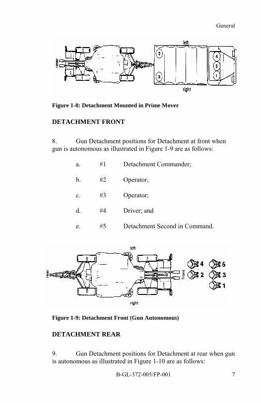
7. Gun Detachment positions for Detachment mounted invehicle as illustrated in Figure 1-8 are as follows:
a. #1 Detachment Commander;
b. #2 Operator;
c. #3 Operator;
d. #4 Driver; and
e. #5 Detachment Second in Command.
General
B-GL-372-005/FP-001 7
Figure 1-8: Detachment Mounted in Prime Mover
DETACHMENT FRONT
8. Gun Detachment positions for Detachment at front whengun is autonomous as illustrated in Figure 1-9 are as follows:
a. #1 Detachment Commander;
b. #2 Operator;
c. #3 Operator;
d. #4 Driver; and
e. #5 Detachment Second in Command.
Figure 1-9: Detachment Front (Gun Autonomous)
DETACHMENT REAR
9. Gun Detachment positions for Detachment at rear when gunis autonomous as illustrated in Figure 1-10 are as follows:

35 mm Twin Gun GDF 005 Drill Book
B-GL-372-005/FP-0018
a. #1 Detachment Commander;
b. #2 Operator;
c. #3 Operator;
d. #4 Driver; and
e. #5 Detachment Second in Command.
Figure 1-10: Detachment Rear (Gun Autonomous)

General
B-GL-372-005/FP-001 9
6
4
SECTION 3GUN CONFIGURATION DURING OPERATION
1 Accessories Case 6 Fuel Cans2 Maintenance Equipment Case 7 Fire Extinguisher3 Weapon Spare Parts Case 8 Ammunition Cases4 MV Measuring Base Case 9 Ammunition Clip Cases5 Exhaust Hose Case 10 Covers
Figure 1-11: Firing Configuration (Gun in Reloading Position)
35 mm Twin Gun GDF 005 Drill Book
B-GL-372-005/FP-00110
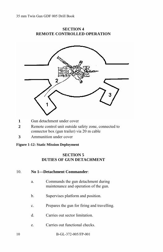
SECTION 4REMOTE CONTROLLED OPERATION
1 Gun detachment under cover2 Remote control unit outside safety zone, connected to
connector box (gun trailer) via 20 m cable3 Ammunition under cover
Figure 1-12: Static Mission Deployment
SECTION 5DUTIES OF GUN DETACHMENT
10. No 1—Detachment Commander:
a. Commands the gun detachment duringmaintenance and operation of the gun.
b. Supervises platform and position.
c. Prepares the gun for firing and travelling.
d. Carries out sector limitation.
e. Carries out functional checks.

General
B-GL-372-005/FP-001 11
f. Operates Gun King sight.
g. Aligns the gun.
h. Checks readiness for action.
i. Engages targets according to orders.
j. Ensures that ammunition and detachment reportsare made.
k. Is responsible for power supply unit (PSU) andgun history books.
l. Reports faults and failure identification (FID)numbers to maintenance personnel.
m. Checks vehicle lighting and brakes on the gun.
n. Implements local defence plan under direction offire unit (FU) Commander.
o. Ensures that maintenance and technical checksaccording to Preventive Maintenance Schedule(refer to C-79-214-000/NY-001, Part 1) areperformed.
11. No 2—Operator:
a. Prepares the gun for firing and travelling.
b. Cocks right weapon.
c. Loads and unload right weapon.
d. Controls cable drums.
e. Manually operates right Automatic Loader (AL).
f. Loads right automatic reloader.
g. Maintains right weapon.

35 mm Twin Gun GDF 005 Drill Book
B-GL-372-005/FP-00112
h. Carries out gun maintenance.
i. Keeps PSU supplied with fuel.
j. Operates Gun King sight as required.
k. Carries out local defence.
12. No 3—Operator:
a. Prepares the gun for firing and travelling.
b. Cocks left weapon.
c. Loads and unloads left weapon.
d. Rolls out field cables to FCU.
e. Manually operates left AL.
f. Loads left automatic reloader.
g. Maintains left weapon.
h. Carries out gun maintenance.
i. Is responsible for data collection.
j. Drives vehicle as required.
k. Carries out local defence.
l. Unloads vehicle.
m. Prepares ammunition.
n. Operates Gun King sight as required.
o. Loads vehicle.
p. Keeps PSU supplied with fuel.

General
B-GL-372-005/FP-001 13
13. No 4—Driver:
a. Drives prime mover.
b. Carries out local defence.
c. Unloads prime mover.
d. Prepares ammunition.
e. Camouflage prime mover.
f. Loads vehicle.
g. Carries out vehicle maintenance.
h. Prepares the gun for firing and travelling asrequired.
i. Loads and unloads left weapon as required.
j. Manually operates left AL.
k. Maintains left weapon.
l. Carries out gun maintenance.
14. No 5—Detachment Second in Command (2IC):
a. Detaches gun from prime mover.
b. Unloads gun boxes.
c. Directs prime mover to shelter.
d. Organizes local defence.
e. Organizes ammunition and fuel supply.
f. Attaches gun to prime mover.
g. Loads prime mover.

35 mm Twin Gun GDF 005 Drill Book
B-GL-372-005/FP-00114
h. Replaces No 1 as required.
i. Operates laser/trigger interrupter.
SECTION 6FORM DETACHMENTS FRONT (OR REAR)
15. On the order "DETACHMENT FRONT (or REAR)" thedetachment falls into two ranks, No 1, No 3 and No 5 from right toleft in the front rank: No 2 and No 4 in the rear covering off No 3and No 5 respectively, with one space between ranks.
16. Dress right and stand at ease (see Figure 1-7).
SECTION 7TELL OFF
17. On the order "TELL OFF" the Detachment Commandernumbers himself "ONE", the man on the right of the rear ranknumbers himself "TWO", his front man "THREE" and so on.
SECTION 8CHANGE ROUND
18. On the order "CHANGE ROUND" No 1 takes one pace tothe rear and one pace to the left.
19. No 3 and No 5 take two short paces to the right.
20. No 2 take’s two short paces to the left.
21. No 4 take’s two short paces to the front.

General
B-GL-372-005/FP-001 15
SECTION 9SAFETY
LASER
22. The laser safety plate on the connector box must always beset to BLUE. This ensures that the laser circuit is interrupted.
23. The laser enable switch must be connected to the connectorbox or to the trigger enable jumper, which is connected to theconnector box. This allows No 2 to "arm" the laser, thus allowingNo 1 to activate it.
24. The headrest contains a limit switch, which must bedepressed before the laser will operate.
25. The laser may be actuated:
a. when engaging a target by using the trackingbutton on the control yoke; and
b. when engaging a target manually by using thelaser/trigger foot switch.
NOTEThe use of the trigger enable jumper and the laser enableswitch is a peacetime requirement. In combat situations theplate will be turned to RED.
DANGER1. The laser beam can cause serious damage to thehuman eye.
2. Wear laser protective glasses when the laser sourceis switched to ON!
35 mm Twin Gun GDF 005 Drill Book
B-GL-372-005/FP-00116
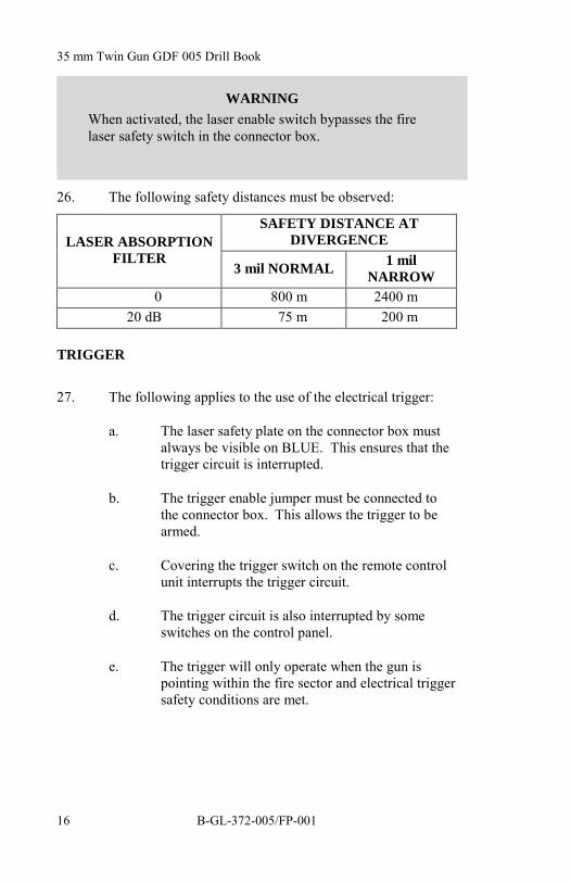
26. The following safety distances must be observed:
SAFETY DISTANCE ATDIVERGENCELASER ABSORPTION
FILTER3 mil NORMAL 1 mil
NARROW0 800 m 2400 m
20 dB 75 m 200 m
TRIGGER
27. The following applies to the use of the electrical trigger:
a. The laser safety plate on the connector box mustalways be visible on BLUE. This ensures that thetrigger circuit is interrupted.
b. The trigger enable jumper must be connected tothe connector box. This allows the trigger to bearmed.
c. Covering the trigger switch on the remote controlunit interrupts the trigger circuit.
d. The trigger circuit is also interrupted by someswitches on the control panel.
e. The trigger will only operate when the gun ispointing within the fire sector and electrical triggersafety conditions are met.
WARNINGWhen activated, the laser enable switch bypasses the firelaser safety switch in the connector box.

General
B-GL-372-005/FP-001 17
SERVO SECTOR/FIRE SECTOR/LASER SECTOR/LIMITED ZONE
28. The servo sector prevents the gun servos from moving thegun outside the limits entered by the operator for the servo section.
29. The fire sector prevents the gun from firing outside thelimits entered by the operator for the fire sector.
30. The laser sector prevents laser emission outside the limitsentered by the operator for the laser sector.
31. A safety fence is erected around the gun, approximately 30cm larger in radius than the gun radius with muzzle velocity (MV)bases attached. This marks the limited zone around the gun whereno one but the gun operator should be while he has control of thegun in the electrical mode.
WARNINGThe trigger enable jumper bypasses the fire laser safetyswitch in the connector box. It provides a continuousenable to the firing circuit.
NOTEThe use of the trigger enable jumper and the laser enableswitch is a peacetime requirement. In combat situations theplate will be turned to RED.
NOTEPersonnel can only enter the limited zone in thecircumstances specifically defined in the procedures.

35 mm Twin Gun GDF 005 Drill Book
B-GL-372-005/FP-00118
PERSONNEL SAFETY
32. All members of the detachment:
a. must wear the correct protective clothing;
b. must wear ear protectors during firing; and
c. must not wear items of clothing, jewellery,watches, etc. that could catch in mechanical parts.
33. No 1 is responsible for the safety of all the members of hisdetachment.
34. No 5 must ensure that no one is in a danger area beforepressing the laser/trigger interrupter.
35. Only climb on or off the gun if the traverse lock is engaged.
36. Within this drill book, all commands written in capitals andenclosed in quotation marks must be given as spoken orders. Thedetachment must react accordingly and acknowledge them uponcompletion.
37. Each member of the detachment should carry a copy of thisdrill book when working with the gun. The drills must be followedprecisely as written.
38. Only one person can be on the gun, seated in the operator'sseat, at any one time during gun operation. If an instructor's seat isfitted, a second person may be strapped into this seat.
TRAVELLING
39. Never drive over the cables.
40. Always make sure that the stop cock lever is in the FULLLOAD (braked) position.
41. Free the tow bar before travelling.
42. Do not drive in reverse with the gun attached.

General
B-GL-372-005/FP-001 19
43. Make sure that the front and rear undercarriages are locked.
44. Verify that the swivel arm lock is engaged in the catch andthat the safety rope is attached.
45. Do not stand between the wheels when moving the gun.
FIRING
46. Make sure that the tow bar is secured and the parking andhand brakes are applied.
47. Ensure that the front and rear undercarriages are locked.
48. Ensure that the stop cock lever is at FULL LOAD.
49. Before levelling the gun ensure that the swivel arms arelocked.
50. When manual loading has been completed always removethe hand ratchet.
51. After unloading, cock the weapons, check the cartridgechamber and raise the barrels into the firing zone before releasingthe breech block.
52. If the automatic loader jams, release tension in the springmotor drive before putting hands inside the loader.
MISFIRE/STOPPAGE SAFETY PROCEDURE
53. If a weapon does not fire after the trigger has been actuatedand the breech block released, and firing has taken place within thelast 20 minutes, the following procedure shall be carried out:
a. the gun operator brings the gun to the loadingposition;
b. reports misfire to the Weapon Safety Officer;
c. sets FIRE SWITCH to SAFE (covered);

35 mm Twin Gun GDF 005 Drill Book
B-GL-372-005/FP-00120
d. sets POWER switch to OFF;
e. sets CONVEYOR MOTOR switch on thetechnical panel to OFF;
f. engages traverse lock;
g. places the yellow flag on the cabin cross bar; and
h. the detachment then evacuates the gun site for aperiod of 20 minutes before taking any furthermeasures.
54. This procedure must also be carried out if a weapon stopsfiring unexpectedly.

35 mm Twin Gun GDF 005 Drill Book
B-GL-372-005/FP-001 21
CHAPTER 2STANDARD OPERATING PROCEDURES
SECTION 1GUN PREPARATION
1. This part of B-GL-372-005/FP-001 35 mm Twin Gun GDF005 Drill Book deals with bringing the gun to such a state that it isable to engage targets autonomously.
2. The procedures can be suspended on No 1's command,while other procedures take place (e.g., fire unit [FU] orientation)once a Menu is completed.
3. If any faults occur (e.g., TROUBLE lamp blinking or on)while preparing for engagement, proceed with Part 4.2, FaultfindingProcedures.
4. The alignment of the gun described in this part is done withan aiming circle operated by the FCU operator. However, if noaiming circle is available, alignment can also be carried out with acompass or on a distant reference point, provided that the angle tothe north can be read off an accurate map.
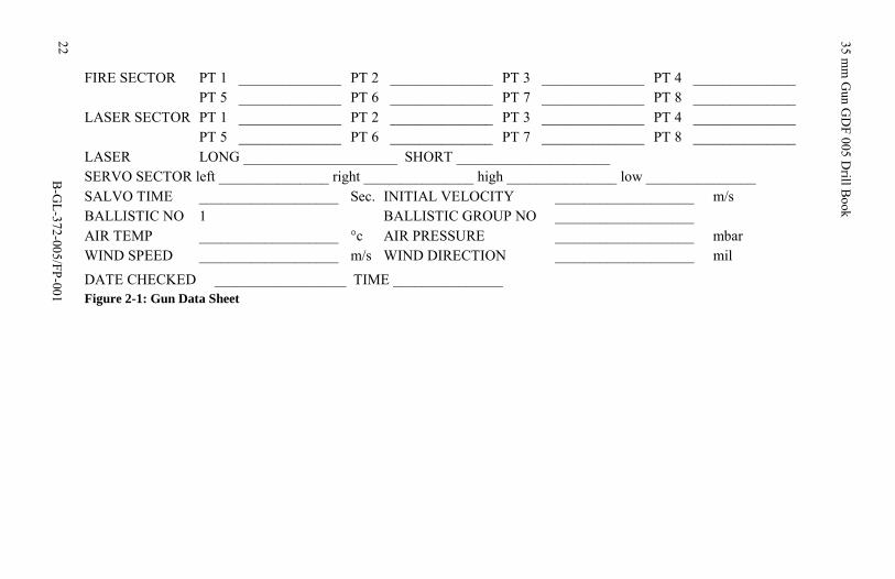
5. The following is an example of a data sheet that could beused to collect all necessary data:
22 35 mm
Gun G
DF 005 D
rill Book
B-G
L-372-005/FP-001
FIRE SECTOR PT 1 ______________ PT 2 ______________ PT 3 ______________ PT 4 ______________PT 5 ______________ PT 6 ______________ PT 7 ______________ PT 8 ______________
LASER SECTOR PT 1 ______________ PT 2 ______________ PT 3 ______________ PT 4 ______________PT 5 ______________ PT 6 ______________ PT 7 ______________ PT 8 ______________
LASER LONG _____________________ SHORT _____________________SERVO SECTOR left _______________ right _______________ high _______________ low _______________SALVO TIME ___________________ Sec. INITIAL VELOCITY ___________________ m/sBALLISTIC NO 1 BALLISTIC GROUP NO ___________________AIR TEMP ___________________ °c AIR PRESSURE ___________________ mbarWIND SPEED ___________________ m/s WIND DIRECTION ___________________ mil
DATE CHECKED __________________ TIME _______________Figure 2-1: Gun Data Sheet

Standard Operating Procedures
B-GL-372-005/FP-001 23
SECTION 2GUN PREPARATION
6. Prepare for Action is normally carried out under cover, closeto the next position the FU will occupy.
7. The purpose is to prepare the gun for rapid deployment and toeliminate any defects or faults.
8. During Prepare for Action, the gun is left hooked to the primemover.
9. If so ordered, the power supply unit (PSU) may be leftlowered and operating.
10. The detachment should report all faults and errors to No 1.
HALT—PREPARE FOR ACTION
No 1 No 2 No 3 No 4 No 5"HALTPREPAREFORACTION"
DismountRoll up airoutlet flap
Dismount
Insert pumphandlePump twiceRemovelocking pinPull stoplever back
Prepareammunition(in vehicle)Prepare MVbases
InstallrefuellingdevicePlace storeson vehicle
Prepareammunition(in vehicle)Prepare MVbases
InstallrefuellingdevicePlace storesin vehicle
Move slidelever downPSU isloweredEngage stoplever
35 mm Twin Gun GDF 005 Drill Book
B-GL-372-005/FP-00124
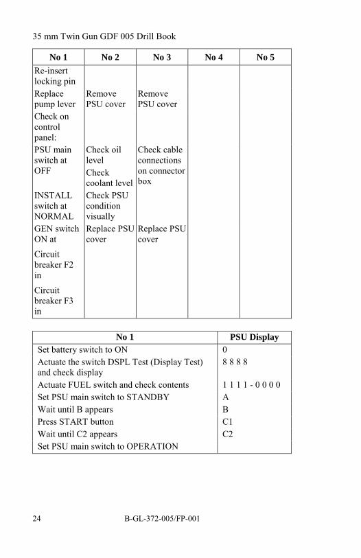
No 1 No 2 No 3 No 4 No 5Re-insertlocking pinReplacepump lever
RemovePSU cover
RemovePSU cover
Check oncontrolpanel:PSU mainswitch atOFF
Check oillevelCheckcoolant level
Check cableconnectionson connectorbox
INSTALLswitch atNORMAL
Check PSUconditionvisually
GEN switchON at
Circuitbreaker F2in
Circuitbreaker F3in
Replace PSUcover
Replace PSUcover
No 1 PSU DisplaySet battery switch to ON 0Actuate the switch DSPL Test (Display Test)and check display
8 8 8 8
Actuate FUEL switch and check contents 1 1 1 1 - 0 0 0 0Set PSU main switch to STANDBY AWait until B appears BPress START button C1Wait until C2 appears C2Set PSU main switch to OPERATION

Standard Operating Procedures
B-GL-372-005/FP-001 25
No 1 No 2/Right No 3/LeftUnfasten maintarpaulin at rearand remove
Unfasten maintarpaulin at frontand remove
Unfasten maintarpaulin at front andremove
Remove sighttarpaulin
Unfasten rearundercarriagetarpaulin
Unfasten rearundercarriagetarpaulin
Release elevationbrake
Remove reloadertarpaulin
Remove reloadertarpaulin
Unlock barrelsupport and lower
Remove automaticloader (AL)tarpaulin
Remove AL tarpaulin
Remove barreltarpaulin
Remove frontundercarriagetarpaulin
Remove frontundercarriagetarpaulin
Remove muzzlebrake and replacewith MV base
Remove muzzle brakeand replace with MVbase
Move reloader to SP(service position)
Move reloader to SP
Check grease levelcontrol button onAutomaticLubrication System(ALs)Cock weapon andrelease tension
Cock weapon andrelease tension
Ensure emptycartridge clip is inloader
Ensure empty cartridgeclip is in loader
Set discharge lever toIM
Set discharge lever toIM
Clamp barrels Load reloader Load reloader
Raise PSU Move reloader to WP(waiting position)
Move reloader to WP

35 mm Twin Gun GDF 005 Drill Book
B-GL-372-005/FP-00126
No 1 No 2/Right No 3/Left
"DETACHMENTREAR, REPORT"
"MOUNT"
Report all faults toNo 1
Report all faults to No 1
HALT—ACTION ACTION ACTION
NOTEThe gun should be brought to the gun marker and the trailer orientedso that the PSU exhaust points towards the direction of threat. If timepermits, No 1 should order the detachment to lay out the lowercamouflage nets and extend the upper camouflage nets.
No 1 No 2 No 3 No 4 No 5Guide vehicle togun marker"HALTACTIONACTIONACTION"
Dismount Dismount Dismount
Insert wheelchockApply rearhand brake
Apply rearhand brake
Disconnectbrake hoseyellow andlightingcable
Disconnectbrake hosered andremovessafety pin
Assistunhookingtow bar
Assistunhookingtow bar
"DRIVEON—HALT"(approximately5 m)
Driveon—halt
Securetow bar(red pin)
Securetow bar(red pin)
Unloadstores
Unloadstores
Lower PSU (ifit was raised)

Standard Operating Procedures
B-GL-372-005/FP-001 27
No 1 No 2 No 3 No 4 No 5Checkreloader isin WP
Checkreloader isin WP
Unlock barrelsand lower
Swing outswivel armlocks it infiringposition
Swing outswivel armlocks it infiringposition
Removeuppercamouflagetarpaulin
Remove fireextinguisherRemoveuppercamouflagetarpaulin
Set INSTALLswitch to LVLONLYRaise gun"UNLOCKWHEELS"Unlock wheelrear left
Unlockwheel rearright
"UNLOCKED"
Unlockwheels front
"UNLOCKED"
Place storesaccording tooperationconfiguration(seeFigure 1-11)
Place storesaccording tooperationconfiguration(seeFigure 1-11)
Tilt wheels"LOCKWHEELS"Lock wheel leftrear
Lock wheelright rear
"LOCKWHEELS"
Lockwheels front
"LOCKWHEELS"
Lower and levelgun

35 mm Twin Gun GDF 005 Drill Book
B-GL-372-005/FP-00128
No 1 No 2 No 3 No 4 No 5Set upsafety fence(if required)
Set upsafety fence(if required)
INSTALLswitchNORMAL
Inspect safetyfence
Checksafety fence
manuallyrotate thebarrels intraverse
Checksafety fence
Adjustfence posts
Movevehicle tocover
PerformReadinessCheck
Controlcable drums
Reel outcable drumsto FCU
Camouflageandmaintain
Carry gunmarker toFCU
Give dataandintercomlines toFCUoperators

Standard Operating Procedures
B-GL-372-005/FP-001 29
READINESS CHECK
No 1 No 2 No 3"READINESS CHECK"Move left reloader to SP(service position). Ensureempty cartridge clip is in ALPress circuit breaker in leftsupport armVerify parallelogram atrequired positionMove left reloader to WPEnsure FAST/SLOW lever isset on SLOWCheck PSU for fuel contentand errorsEnsure barrel clamp is fullyhome in firing position
Prepareammunition
Prepareammunition
Check data cable connectioncomms:Panel plate blue, activate all12 circuit breakers andCONNECTS trigger enablejumper boxMove right reloader to SPEnsure empty cartridge clip isin ALpress circuit breaker in rightsupport armverify parallelogram atrequired positionMove right reloader to WPEnsure all control panelswitches are up (ON) positionexcept AMMUNITIONswitch, which should be set toREST 3
35 mm Twin Gun GDF 005 Drill Book
B-GL-372-005/FP-00130
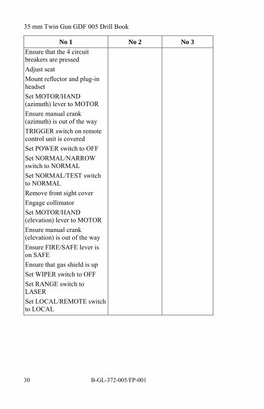
No 1 No 2 No 3Ensure that the 4 circuitbreakers are pressedAdjust seatMount reflector and plug-inheadsetSet MOTOR/HAND(azimuth) lever to MOTOREnsure manual crank(azimuth) is out of the wayTRIGGER switch on remotecontrol unit is coveredSet POWER switch to OFFSet NORMAL/NARROWswitch to NORMALSet NORMAL/TEST switchto NORMALRemove front sight coverEngage collimatorSet MOTOR/HAND(elevation) lever to MOTOREnsure manual crank(elevation) is out of the wayEnsure FIRE/SAFE lever ison SAFEEnsure that gas shield is upSet WIPER switch to OFFSet RANGE switch toLASERSet LOCAL/REMOTE switchto LOCAL
Standard Operating Procedures
B-GL-372-005/FP-001 31
No 1
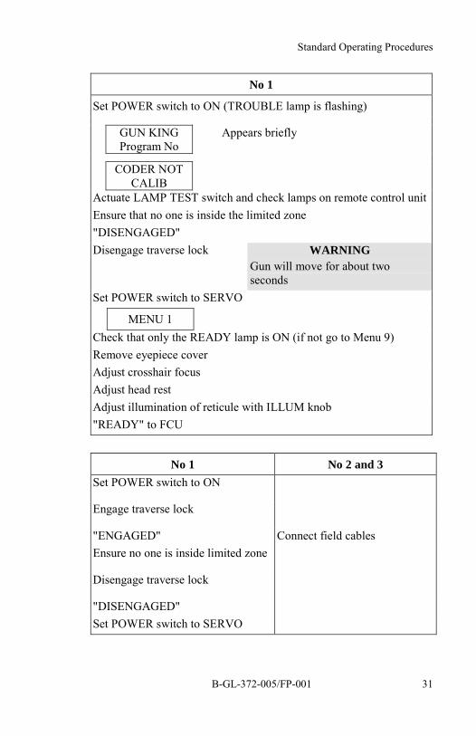
Set POWER switch to ON (TROUBLE lamp is flashing)
GUN KINGProgram No
Appears briefly
CODER NOTCALIB
Actuate LAMP TEST switch and check lamps on remote control unitEnsure that no one is inside the limited zone"DISENGAGED"Disengage traverse lock WARNING
Gun will move for about twoseconds
Set POWER switch to SERVO
MENU 1Check that only the READY lamp is ON (if not go to Menu 9)Remove eyepiece coverAdjust crosshair focusAdjust head restAdjust illumination of reticule with ILLUM knob"READY" to FCU
No 1 No 2 and 3Set POWER switch to ON
Engage traverse lock
"ENGAGED" Connect field cablesEnsure no one is inside limited zone
Disengage traverse lock
"DISENGAGED"Set POWER switch to SERVO

35 mm Twin Gun GDF 005 Drill Book
B-GL-372-005/FP-00132
VERIFY SERVO SECTOR [MENU 10] AND TRAININGSIMULATOR 2 MODE [MENU 23] SETTINGS
No 1
MENU 10 Ensure that Menu 10 is selected.
RET
SECT LIM MOUNT = 0
If SEC LIM MOUNT = 1 enter 0
RET
MENU 1
NOTE
To set the servo sector refer toSection 3.1.11.
MENU 23 Ensure that Menu 23 is selected.
RET
TRAINING MODE = 0
If TRAINING_MODE = 1 enter 0
RET
MENU 1

Standard Operating Procedures
B-GL-372-005/FP-001 33
DRIFT TRIM [MENU 1]
No 1
CAUTIONDo not touch the control yoke before or when Menu 1 is running
MENU 1 Ensure Menu 1 is selected
RET
DRIFT TRIMDrift trim program runsautomatically
MENU 2
SET GUN ALIGNMENT [MENU 2]
Figure 2-2: Gun Alignment

35 mm Twin Gun GDF 005 Drill Book
B-GL-372-005/FP-00134
No 1 Aiming circleOperator
Aiming circle Operator set up theAiming circle about 100 m from thegun
MENU 2Ensure Menu 2 isselected
Set up and levelAiming circle
Orient the Aimingcircle 3200 mils tonorth
RET
ALIG CHECK?
RET
ALIG PROC?
YES
ALIG PROC →RET
Sight roughly on Aiming circle
Set POWER switch to ON
Change both MOTOR/HAND levers toHAND
Sight accurately on Aiming circle usingmanual drive
Lock drive handles
Inform Aiming circle Operator by holdingup a hand
Sight on gunperiscope
Raise hand toinform No 1 oforientation
Sent angle to northto No 1 by usingarms signals
RET
ORIENT ... MIL
When data received from Aiming circleOperator, confirm data with armssignals and enter the angle to north(range 0 .. 6399.9 mils)

Standard Operating Procedures
B-GL-372-005/FP-001 35
No 1 Aiming circleOperator
ORIENT 1002MIL
RET
FIX1 CHECK?
NOTE
During night deployment, No 1 will send No 2 to the Aimingcircle to receive angle to north.

35 mm Twin Gun GDF 005 Drill Book
B-GL-372-005/FP-00136
SET FIXED POINTS AND LOADING POSITION [MENU 2]
No 1
RET
FIX1 PROC?
YES
FIX1 PROC - > RET
Sight on FCU position
RET
FIX2 CHECK?
RETSelect terrain point (no more than 4 km away)
FIX2 PROC?
YES
FIX2 PROC - > RETSight exactly on the terrain point
RET
LOAD PROC?
YES
LOAD PROC - > RET
Traverse gun to loading position
RET
MENU 3

Standard Operating Procedures
B-GL-372-005/FP-001 37
SET LASER SECTOR [MENU 3]
NOTE
1. Laser sector limits:
a. No laser sector limitation—choose 3 points in thedirection of each levelling jack with the barrels atmaximum depression, or
b. Terrain limitation, or
c. Laser window
No 1
MENU 3 Ensure that Menu 3 is selected.
RET
LSECT CHECK?
RET
LSECT PROC?
YES
Azimuth Elevation 1 Current position is displayed.
Sight on sector point No 1
Azimuth Elevation 1
RET
Sight on sector point No 2
Azimuth Elevation 2The angle between points must notexceed 3200 mils.
RET
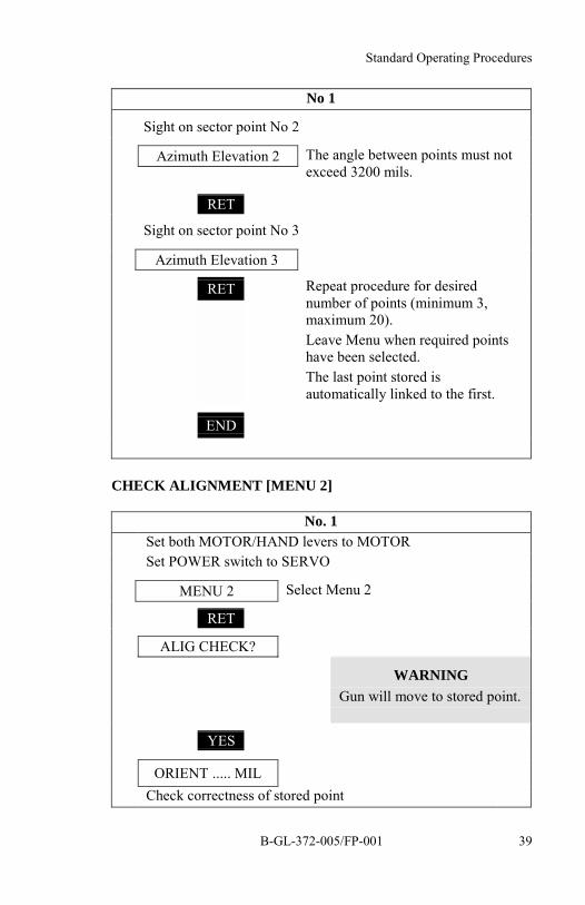
Sight on sector point No 3
Azimuth Elevation 3

35 mm Twin Gun GDF 005 Drill Book
B-GL-372-005/FP-00138
No 1RET
END
Repeat procedure for desirednumber of points (minimum 3,maximum 20).Leave Menu when required pointshave been selected.The last point stored isautomatically linked to the first.
SET FIRE SECTOR [MENU 4]
NOTE
1. Fire sector limits:
a. No fire sector limitation—choose 3 points in thedirection of each levelling jack with the barrels atmaximum depression, or
b. Terrain limitation, or
c. Firing window
No 1
MENU 4 Ensure that Menu 4 is selected.
RET
FSECT CHECK?
RET
FSECT PROC?
YES
Azimuth Elevation 1 Current position is displayed.
Sight on sector point No 1
Azimuth Elevation 1
RET
Standard Operating Procedures
B-GL-372-005/FP-001 39
No 1
Sight on sector point No 2
Azimuth Elevation 2 The angle between points must notexceed 3200 mils.
RET
Sight on sector point No 3
Azimuth Elevation 3
RET Repeat procedure for desirednumber of points (minimum 3,maximum 20).Leave Menu when required pointshave been selected.The last point stored isautomatically linked to the first.
END
CHECK ALIGNMENT [MENU 2]
No. 1Set both MOTOR/HAND levers to MOTORSet POWER switch to SERVO
MENU 2 Select Menu 2
RET
ALIG CHECK?
WARNINGGun will move to stored point.
YES
ORIENT ..... MILCheck correctness of stored point
35 mm Twin Gun GDF 005 Drill Book
B-GL-372-005/FP-00140
No. 1
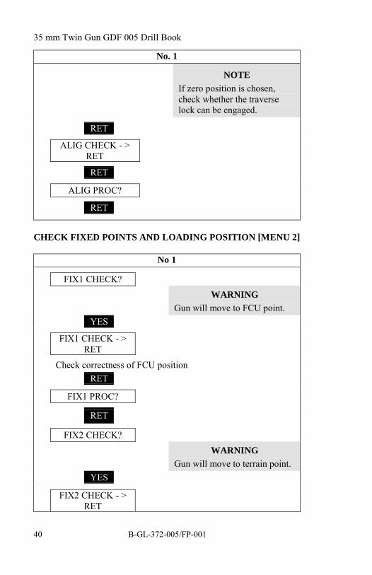
NOTEIf zero position is chosen,check whether the traverselock can be engaged.
RET
ALIG CHECK - >RET
RET
ALIG PROC?
RET
CHECK FIXED POINTS AND LOADING POSITION [MENU 2]
No 1
FIX1 CHECK?WARNING
Gun will move to FCU point.YES
FIX1 CHECK - >RET
Check correctness of FCU positionRET
FIX1 PROC?
RET
FIX2 CHECK?WARNING
Gun will move to terrain point.YES
FIX2 CHECK - >RET

Standard Operating Procedures
B-GL-372-005/FP-001 41
No 1
Check correctness of FCU position
RET
FIX2 PROC?
RET
LOAD PROC?
RET
MENU 3
WARNINGGun will move to loadingposition.
Press LOAD POS button.
CHECK LASER SECTOR [MENU 3]
No 1
MENU 3 Ensure that Menu 3 is selected.
RET
LSECT CHECK?
WARNINGGun will move to laser sectorpoint 1.
YES
Azimuth Elevation 1
Check position of sector point No 1
WARNINGGun will move to laser point 2.
RET

35 mm Twin Gun GDF 005 Drill Book
B-GL-372-005/FP-00142
No 1Azimuth Elevation 2
Continue with this procedure until sector point No 1 isdisplayed again.
END Leave Menu 3 when all pointshave been checked.
MENU 4
CHECK FIRE SECTOR [MENU 4]
No 1
MENU 4 Ensure that Menu 4 is selected.
RET
FSECT CHECK?
WARNINGGun will move to fire sectorpoint 1.
YES
Azimuth Elevation 1
Check position of sector point No 1
WARNINGGun will move to fire sectorpoint 2.
RET
Azimuth Elevation 2Continue with this procedure until sector point No 1 is displayedagain.
END Leave Menu 4 when all points have beenchecked.
MENU 5

Standard Operating Procedures
B-GL-372-005/FP-001 43
SET DISTANCES [MENU 5]
NOTEThis procedure can only be carried out after all the laser safetyprecautions have been met (refer to section 1.9.1).
No 1 No 5"MEASURE RANGE TO FIXED POINT"
MENU 5 Ensure that Menu 5 isselected
RET
CHANGE DATA?
YES
LASER RAN .... M Last range measured isdisplayed
Sight on fixed point roughlyChange MOTOR/HAND levers to HANDLook through periscope and sight on fixedpoint exactlyLock drive handlesSet NORMAL/NARROW switch toNARROWEnsure LASER RANGE switch is set atLASER
If safetyconditions havebeen met presslaser enableswitch"LASERFREE"
"READY"

35 mm Twin Gun GDF 005 Drill Book
B-GL-372-005/FP-00144
No 1 No 5Look through periscope and press head restOpen cover of laser/trigger foot switchPress laser/trigger foot switch briefly
LASER RAN .... MCurrent measuredvalue displayed.
Read out measured rangeRepeat procedure for measurement ofadditional fixed points"RANGE MEASURING FINISHED"Ensure laser/trigger foot switch is coveredChange NORMAL/NARROW switch toNORMALChange MOTOR/HAND lever to MOTOREnsure that only READY lamp is ON
Release laserenable switch
No 1
LASER RAN .... M
RET
LONG RAN .... M
Enter range for fixed distance LONG
RET
SHORT RAN .... M
Enter range for fixed distance SHORT
RET
MENU 6

Standard Operating Procedures
B-GL-372-005/FP-001 45
ENTER FIRING DATA [MENU 6]
No 1
MENU 6 Ensure that Menu 6 is selected
RET
CHANGE DATA?
YES
SALVOTIM .... SECEnter required burst duration (range 0.2-2.5 sec)
RET
BAL NO.Enter required ballistic number (1 for normal, 2 for shorttrajectory, 3 for AHEAD ammunition)
if 1: BAL_NO 1
RET
BAL1_GROUP = ..Set required ballistic groupnumber
1 for target practice (TP-T)ammunition2 for high explosiveincendiary (HEI)ammunition
RET
VO .... M/SEnter initial muzzle velocity (range 750-1350 m/s)
RET
FIRED L ... RD
END
if 2: BAL_NO 2
RET

35 mm Twin Gun GDF 005 Drill Book
B-GL-372-005/FP-00146
No 1VO .... M/S
Set initial muzzle velocity (range 750-1350 m/s)
RET
FIRED L ... RD
END
MENU 7
if 3: BAL_NO 3
RET
VO .... M/SSet initial muzzle velocity (range 750-1350 m/s)
RET
TIME_FIXED = 0If TIME_FIXED = 1 enter a 0
RET
TZ_FIX....MS
END
MENU 7"FIRING DATA SET"
ENTER METEOROLOGICAL DATA [MENU 7]
No 1
MENU 7 Ensure that Menu 7 is selected.
RET
CHANGE DATA?
YES
Standard Operating Procedures
B-GL-372-005/FP-001 47
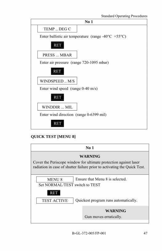
No 1
TEMP .. DEG C
Enter ballistic air temperature (range -40°C +55°C)
RET
PRESS ... MBAR
Enter air pressure (range 720-1095 mbar)
RET
WINDSPEED .. M/S
Enter wind speed (range 0-40 m/s)
RET
WINDDIR ... MIL
Enter wind direction (range 0-6399 mil)
RET
QUICK TEST [MENU 8]
No 1
WARNINGCover the Periscope window for ultimate protection against laserradiation in case of shutter failure prior to activating the Quick Test.
MENU 8 Ensure that Menu 8 is selected.Set NORMAL/TEST switch to TEST
RET
TEST ACTIVE Quickest program runs automatically.
WARNINGGun moves erratically.

35 mm Twin Gun GDF 005 Drill Book
B-GL-372-005/FP-00148
No 1
MENU 9
Set NORMAL/TEST switch to NORMALIf TROUBLE lamp is not flashing or on finish Quick TestIf TROUBLE is flashing check error codes
ERROR MESSAGES [MENU 9]
No 1
MENU 9 Ensure that Menu 9 is selected.
RET
NO ERRORS When no errors are present.
END
MENU 10
Error Code When errors are present.
RET
END Press RET until all error numbers havebeen read out and written down.
MENU 10
ALARM SECTORS
11. For autonomous firing (without FCU), the DetachmentCommander must organize an orientation system for his gun. Thissystem enables observers to designate the target that No 1 has toengage.
a. Azimuth:
(1) Clock system with direction 12 to north oron a reference object.
Standard Operating Procedures
B-GL-372-005/FP-001 49
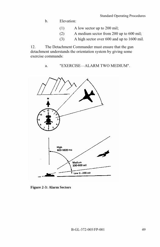
b. Elevation:
(1) A low sector up to 200 mil;(2) A medium sector from 200 up to 600 mil;(3) A high sector over 600 and up to 1600 mil.
12. The Detachment Commander must ensure that the gundetachment understands the orientation system by giving someexercise commands:
a. "EXERCISE—ALARM TWO MEDIUM".
Figure 2-3: Alarm Sectors

35 mm Twin Gun GDF 005 Drill Book
B-GL-372-005/FP-00150
FIRE TRIGGER CHECK
NOTE
This procedure can only be carried out after all trigger safetyprecautions have been met. Refer to section 1.9.2.
DANGER
Make sure the gun is not loaded.
No 1 No 2
"FIRE TRIGGER CHECK"
Ensure that:
AMMUNITION switch is atREST 3
CONVEYOR MOTOR switch isON
READY lamp is on
RANGE switch is at LONG
Rotate barrels into fire sector
Set TRIGGER switch on controlbox to ON
"FIRING"
Press TRACKING button (shortalarm tone is audible)
Press FIRE SAFETY and FIREBARS—both triggers released
Press TRACKING button twice toreturn to READY status
Continue this procedure to checkfire sector (3-4 times)
Set TRIGGER switch to OFF

Standard Operating Procedures
B-GL-372-005/FP-001 51
No 1 No 2Set RANGE switch to LASER
"TRIGGER CHECK FINISHED"
WARNINGIf no further firing/laser training is to be carried out return the gunto a safe condition by removing laser enable switch and the triggerenable jumper after the fire trigger check and prior to loading.
LOADING
DANGER1. Only feed weapons when ordered.2. Make sure Firing Maintenance has been carried out (refer tosection 3.2).
No 1 Nos 2 and 3"LOADING" Move behind loading
position outside safety fenceEnsure that TRIGGER switch onremote control unit is coveredEnsure that mechanical firing lever ison SEnsure that READY lamp is on
WARNINGGun moves.
Press LOAD POS buttonSet POWER switch to ON and backto SERVOMove the barrels approximatelyhorizontallySet POWER switch to ONEngage traverse lock"ENGAGED"

35 mm Twin Gun GDF 005 Drill Book
B-GL-372-005/FP-00152
No 1 Nos 2 and 3"LOAD"
Move reloaders to SPEnsure that discharge leveris in position IMEnsure that an emptycartridge clip is properlyplaced in the ALsCock weaponsRelease cocking cablesFill reloaders withmaximum 12 cartridge clipsMove reloaders to WP"NO 2/3 ... CARTRIDGECLIPS LOADED"
Write down the number of cartridgeclips loaded
Move behind safety fence
Ensure no one is inside safety fenceDisengage traverse lock"DISENGAGED"
Set POWER switch to SERVOCheck that READY lamp is onPress AUTOM LOAD button(visually check feeler arms)Lower barrels
"GUN LOADED"
NOTETo bring gun to the fully loaded stage, carry on with the proceduresdetailed in sections 2.3.5 and 2.3.6.
LOADING: INITIALISE AMMUNITION ACCOUNT
No 1
MENU 6

Standard Operating Procedures
B-GL-372-005/FP-001 53
No 1
RET Press RET 7 times.
FIRED PRESET?
YES Resets firing counter to 0.
AMM FULL?
RET
AMM EMPTY?
YES Resets ammunition reserve counter to 0.
AMMO RELO+?MAG
Enter total number of cartridge clips loaded for both sidesAsk FCU permission to feed
UNLOAD
No 1 Nos 2 and 3Ensure trigger switch iscoveredPress LOAD POSbuttonSet POWER switch isONEngage traverse lock
"ENGAGED"
Set CONVEYORMOTOR switch to OFFSet MOTOR/HANDlevers to HAND
Lower barrelsapproximately 0 miland brake elevationdrive handle

35 mm Twin Gun GDF 005 Drill Book
B-GL-372-005/FP-00154
No 1 Nos 2 and 3
"UNLOAD" Move reloaders to SP.Set discharge levers to OA.
DANGER
The spring motor may still be wound with enough power to operatethe feed mechanism at full speed.
No 1 No 2 No 3 Nos 4 and 5Remove fullcartridge clipsfrom AL andgive to No 4Set dischargelever at IMCock weaponsand do notrelease cableOpen weaponprotective cover
Remove fullcartridge clips fromAL and give to No 4Set discharge leverat IMCock weapon anddo not release cable
Placecartridgeclips inammunitionboxes
Open weapon covers completely
WARNINGBeware of the weapon protective coveroverhead
Remove rounds lying on feed tray andput them on an empty cartridge clip
Close weapon covers and open again
Continue procedure until no rounds areleft on the feed tray

Standard Operating Procedures
B-GL-372-005/FP-001 55
No 1 No 2 No 3
Set rightCONVEYORMOTOR switch toON forapproximately 3seconds
Set leftCONVEYORMOTOR switch toON forapproximately 3seconds
Inspect weapons
"CANNONSCLEAR"
Report CANNONSCLEAR to FCU
Set AMMUNITIONswitches to REST 3
Close weapon cover
"FEED RIGHT"
Open weapon cover
Check that cartridgechamber feed tryand AL are free ofrounds
"NO 2UNLOADED"
Close weapon cover
Close weaponprotective cover
Release cockingcable
Put an emptycartridge clip in AL
Fetch reloaderunloading device
Unload reloader
Leave weapon coveropen
Close weapon cover
"FEED LEFT"
Open weapon cover
Check that cartridgechamber feed trayand AL are free ofrounds
"NO 3 UNLOADED"
Close weapon cover
Release cockingcable
Put an emptycartridge clip in AL
Fetch reloaderunloading drive
Unload reloader
Nos 4 and 5 receive the full cartridge clipsfrom Nos 2 and 3 and place them inammunition boxes.
Move reloader toWP
Move reloader to WP
35 mm Twin Gun GDF 005 Drill Book
B-GL-372-005/FP-00156
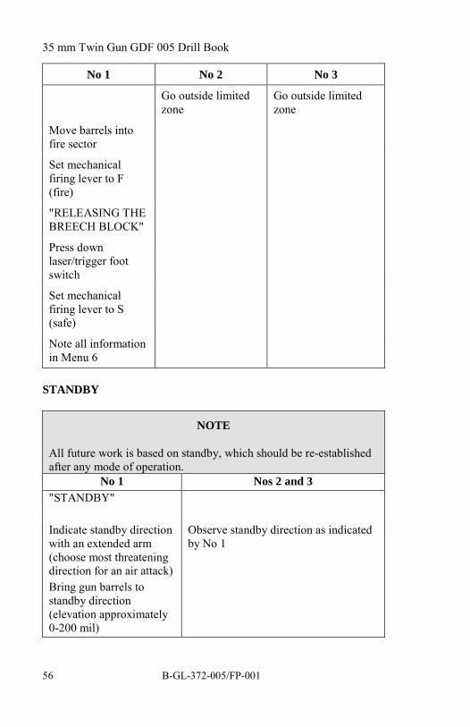
No 1 No 2 No 3
Go outside limitedzone
Go outside limitedzone
Move barrels intofire sector
Set mechanicalfiring lever to F(fire)
"RELEASING THEBREECH BLOCK"
Press downlaser/trigger footswitch
Set mechanicalfiring lever to S(safe)
Note all informationin Menu 6
STANDBY
NOTE
All future work is based on standby, which should be re-establishedafter any mode of operation.
No 1 Nos 2 and 3"STANDBY"
Indicate standby directionwith an extended arm(choose most threateningdirection for an air attack)Bring gun barrels tostandby direction(elevation approximately0-200 mil)
Observe standby direction as indicatedby No 1

Standard Operating Procedures
B-GL-372-005/FP-001 57
No lEnsure that:POWER switch on SERVO
MENU 1 Select Menu 1
TRIGGER switch on remote control unit is covered (S position)
Mechanical firing lever at S
Laser/trigger foot switch is covered
On control panel all switches up (ON)
NORMAL/NARROW switch at NORMAL
NORMAL/TEST switch at NORMAL
LOCAL/REMOTE switch at LOCAL
WIPER switch is off
RANGE switch is at LASER
Gas shield is up
Only READY lamp is illuminated
If trigger must be on:Set TRIGGER switch to F (fire), cover is opened
"TRIGGER IS OPEN"
SECTION 3GUN/FIRE UNIT INTEGRATION
INTRODUCTION
13. The FCU must compensate for the parallax condition thatexists between the FCU and the gun.
14. Computation of the parallax values (lateral displacement,vertical displacement) is carried out by the FCU computer, based onslant range, lateral displacement angles and angle of sight."Orientation" consists of determining these values.
35 mm Twin Gun GDF 005 Drill Book
B-GL-372-005/FP-00158
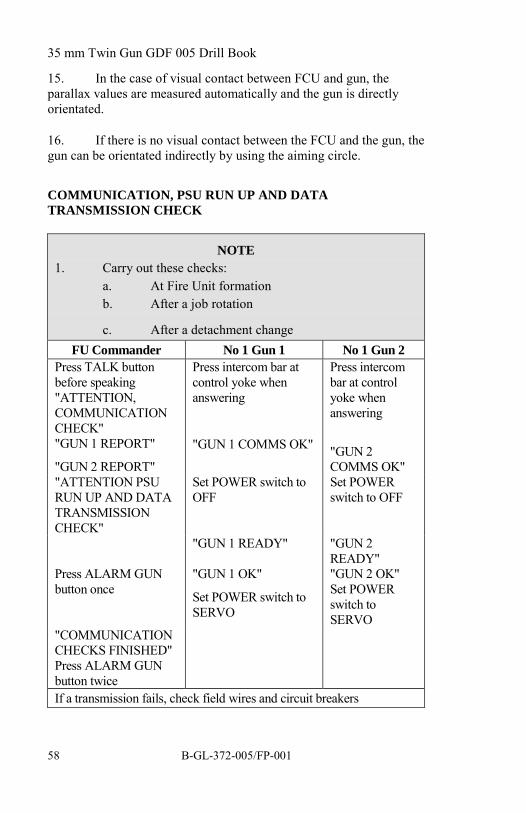
15. In the case of visual contact between FCU and gun, theparallax values are measured automatically and the gun is directlyorientated.
16. If there is no visual contact between the FCU and the gun, thegun can be orientated indirectly by using the aiming circle.
COMMUNICATION, PSU RUN UP AND DATATRANSMISSION CHECK
NOTE1. Carry out these checks:
a. At Fire Unit formationb. After a job rotation
c. After a detachment changeFU Commander No 1 Gun 1 No 1 Gun 2
Press TALK buttonbefore speaking"ATTENTION,COMMUNICATIONCHECK""GUN 1 REPORT"
"GUN 2 REPORT"
Press intercom bar atcontrol yoke whenanswering
"GUN 1 COMMS OK"
Press intercombar at controlyoke whenanswering
"GUN 2COMMS OK"
"ATTENTION PSURUN UP AND DATATRANSMISSIONCHECK"
Set POWER switch toOFF
Set POWERswitch to OFF
"GUN 1 READY" "GUN 2READY"
Press ALARM GUNbutton once
"GUN 1 OK"
Set POWER switch toSERVO
"GUN 2 OK"Set POWERswitch toSERVO
"COMMUNICATIONCHECKS FINISHED"Press ALARM GUNbutton twiceIf a transmission fails, check field wires and circuit breakers

Standard Operating Procedures
B-GL-372-005/FP-001 59
DIRECT ORIENTATION
Figure 2-4: Direct Orientation
FUCommander
No 1
"ATTENTIONGUN 1 (2)"
"DIRECTORIENTATION"
Report to FU Commander"GUN 1 (2): DIRECT ORIENTATION"
Ensure mechanical firing lever and TRIGGERswitch are at S
MENU 2 Select Menu 2
RET
ALIG CHECK?
RET
ALIG PROC?
RET
FIX1 CHECK?

35 mm Twin Gun GDF 005 Drill Book
B-GL-372-005/FP-00160
FUCommander
No 1
YES
WARNINGGun will move tofix point 1.
FIX1 CHECK -> RET
RET
FIX1 PROC?
YES
FIX1 PROC -> RET
Set POWER switch to ON
Change MOTOR/HAND levers to HAND
Open reflector
Look through periscope and sight on whitecrosshair of FCU TV camera
Lock drive handle and check alignment again
Report to FCU Commander
"GUN 1 (2): ORIENTATION FINISHED"
"GUN 1 (2):ORIENTATIONFINISHED"
Report to FU Commander"GUN 1 (2): FCU SIGHTED ON"
RET
FIX2 CHECK?
END
MENU 3
MENU 1 Select Menu 1

Standard Operating Procedures
B-GL-372-005/FP-001 61
FUCommander
No 1
Close reflectorChange MOTOR/HAND lever to MOTORSet POWER switch to SERVOBring gun to standby
INDIRECT ORIENTATION
Figure 2-5: Indirect Orientation
FU Commander No 1 Nos 2 and 3
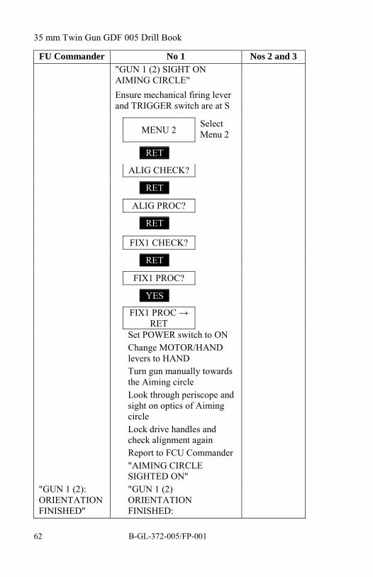
"ATTENTIONGUN 1 (2):INDIRECTORIENTATION"(FCU carries outalignment withAiming circle)"ATTENTIONGUN 1 (2):SIGHT ONAIMINGCIRCLE"
Report to FU Commander"ATTENTION GUN 1 (2):INDIRECT ORIENTATION"
35 mm Twin Gun GDF 005 Drill Book
B-GL-372-005/FP-00162
FU Commander No 1 Nos 2 and 3"GUN 1 (2) SIGHT ONAIMING CIRCLE"Ensure mechanical firing leverand TRIGGER switch are at S
MENU 2SelectMenu 2
RET
ALIG CHECK?
RET
ALIG PROC?
RET
FIX1 CHECK?
RET
FIX1 PROC?
YES
FIX1 PROC →RET
Set POWER switch to ONChange MOTOR/HANDlevers to HANDTurn gun manually towardsthe Aiming circleLook through periscope andsight on optics of AimingcircleLock drive handles andcheck alignment againReport to FCU Commander"AIMING CIRCLESIGHTED ON"
"GUN 1 (2):ORIENTATIONFINISHED"
"GUN 1 (2)ORIENTATIONFINISHED:

Standard Operating Procedures
B-GL-372-005/FP-001 63
FU Commander No 1 Nos 2 and 3
RET
FIX2 CHECK?
END
MENU 3
MENU 1 SelectMenu 1
Set MOTOR/HAND leversto MOTORSet POWER switch toSERVOBring gun to standby
"ATTENTIONALIGNMENTCHECK:REFERENCEPOINT NO ..."
Stay out oflimited zone
"GUN 1 (2) ALIGNMENTCHECK: REFERENCEPOINT NO ..."
ALIGNMENT CHECK
FU Commander No 1 Nos 2 and 3
When alarm tone sounds once,switch LOCAL/REMOTEswitch to REMOTE
Look through optical systemand estimate how many milsthe centre point deviates intraverse and elevation from thereference point
Report to FU Commander
"DEVIATION GUN 1 (2)AZIMUTH LEFT/RIGHT ... MILELEVATION UP/DOWN ... MIL"

35 mm Twin Gun GDF 005 Drill Book
B-GL-372-005/FP-00164
FU Commander No 1 Nos 2 and 3
When alarm tone sounds twice,switch LOCAL/REMOTEswitch to LOCAL
"ALIGNMENTCHECKFINISHED"
Report to FU Commander andNo’s 2 and 3
"GUN 1 (2) ALIGNMENTCHECK FINISHED"
Brings gun barrels to standbydirection
Bring gun to previous state ofreadiness
ZERO TEST
NOTE
The zero test is designed as a dynamic orientation check withoutleading angle calculations.
FU Commander No 1 Nos 2 and 3"ATTENTIONGUN 1 (2):ZERO TEST"
Stay out oflimited zone
"GUN 1 (2) ZERO TEST"When alarm tone sounds once,switch LOCAL/REMOTEswitch to REMOTE
"REPORTDEVIATION"
Look through optical systemand estimate how many milthe centre point deviates intraverse and elevation fromthe targetReport to FU Commander(several times at differentranges)

Standard Operating Procedures
B-GL-372-005/FP-001 65
FU Commander No 1 Nos 2 and 3"GUN 1 (2) AZIMUTHLEFT/RIGHT ... MIL;ELEVATION HIGH/LOW ...MIL"When alarm tone soundstwice, switchLOCAL/REMOTE switch toLOCAL
"ZERO TESTFINISHED:
"GUN 1 (2) ZERO TESTFINISHED"Bring the gun barrels tostandby direction
FICTITIOUS TARGET FIRING
NOTE
Whenever possible carry out fictitious target firing with liveammunition to ensure the function and accuracy of the complete fireunit. If permission for live firing is not granted, carry out the sameprocedure to ensure the function of the trigger actuation from theFCU.
FCUCommander
No 1 Safety Personnel(if applicable)
"ATTENTIONGUN 1 (2)PREPARE FORFICTITIOUSTARGETFIRING"
Prepare FCU forfictitious targetfiring
"GUN 1 (2)FICTITIOUSTARGET FIRING"
Set AMMUNITIONswitch to REST 10
Ensure Menu 9 showsno errors
Take post

35 mm Twin Gun GDF 005 Drill Book
B-GL-372-005/FP-00166
FCUCommander
No 1 Safety Personnel(if applicable)
Press ALARMGUN once
Ensure READY lightis illuminated
Set TRIGGER switchto F
Wait for alarm tone
SwitchLOCAL/REMOTEswitch to REMOTE
"ATTENTIONFICTITIOUSTARGETFIRING 3, 2, 1,FIRE"
Press FIREbutton
Observe TV
"GUN 1 (2)REPORT"
Check readiness ofsafety personnel(ifapplicable)
"GUN 1 (2) READYFOR FICTITIOUSTARGET FIRING"
"GUN 1 (2) BOTHBARRELS OK"
If safety conditions aremet, press laser orlaser/triggerinterrupter(s)
If safety conditions aremet, permit laser andfire from Fire Controland Select System(FCSS)
Release interrupter(s)

Standard Operating Procedures
B-GL-372-005/FP-001 67
FCUCommander
No 1 Safety Personnel(if applicable)
"FICTITIOUSTARGETFIRINGFINISHED"
SwitchLOCAL/REMOTEswitch to LOCAL
Set TRIGGER switchto S (safe)
"GUN 1 (2)FICTITIOUSTARGET FIRINGFINISHED"
Prohibit laser and firefrom FCSS
SECTION 4TARGET ENGAGEMENT
INTRODUCTION
17. The salvo time recommended for local firing is 0.5 seconds.For remote controlled firing, the fire duration is controlled by theFCU. The gun is permanently on standby. The FU Commander givesthe state of readiness (PSU on STANDBY or OPERATION).Whenever possible, the FCU remotely controls the firing at a target.
LOCAL ENGAGEMENT WITH LASER RANGEFINDER
18. Standby procedures carried out (TRIGGER safety switchopen). The short tone on the alarm tone system only sounds if a lasersafety condition is not met. This is the normal procedure for targetengagement. No 1 engages targets, designated by either the FCU orobservers.

35 mm Twin Gun GDF 005 Drill Book
B-GL-372-005/FP-00168
LOCAL ENGAGEMENT WITH FIXED DISTANCE
19. Standby procedures carried out (TRIGGER safety switchopen). Ground targets can also be engaged with fixed distanceSHORT or LONG. This procedure is only used in an emergencywhen the laser is not operating. No 1 engages targets, designated byeither the FCU or observers.
LOCAL TAKE OVER/REMOTE ACQUISITION
20. Whenever "GUN ALARM" from the FCU is given, the gunhorn sounds once and the operator switch the LOCAL/REMOTEswitch to REMOTE. Remotely controlled firing is not furtherdescribed in this chapter.
21. Whenever "END OF GUN ALARM" is given, the gun hornsounds twice and the operator switches the LOCAL/ REMOTE switchto LOCAL. The operator must always be ready to take over trackingfrom the FCU and to fire in local mode with or without therangefinder.
22. Take Over is only done on the FU Commander's order.
23. Standby procedures carried out (TRIGGER safety switchopen). This procedure is normally carried out with the laserrangefinder (also possible with fixed distance).
24. In the case of remotely controlled firing, the after firingprocedures stay the same as described in this part.
25. When taking over from the FCU, No 5 is required to press thelaser/trigger interrupter when all safety precautions are met.
FUCommander No 1 Alarm Tone
(Sight System)
Gun horn sounds once
TRIGGER switch ON
AMMUNITIONswitch is REST 10

Standard Operating Procedures
B-GL-372-005/FP-001 69
FUCommander No 1 Alarm Tone
(Sight System)
SwitchLOCAL/REMOTEswitch to REMOTE
NO TONE
WARNINGGun acquires target
Look through opticalsystem, check targettracking
"ATTENTIONGUN 1 (2)TAKE OVER"
Press TRACKINGbutton briefly whilepressing head rest
MEDIUM TONE
Carry out visualidentification friend orfoe (IFF)
Continue smoothtracking
Press FIRE SAFETYBAR
LONG TONE
"ATTENTIONGUN 1 (2)REMOTE"
Press FIRE switchwhile keeping FIRESAFETY BARdepressed
LONG TONE
Press TRACKINGbutton twice to returnto LOCAL tracking
MEDIUM/LONGTONE
Press TRACKINGbutton once to returnto REMOTE tracking
NO TONE
Gun horn sounds twice
Switch to LOCAL
Close TRIGGERswitch
Go to standby
35 mm Twin Gun GDF 005 Drill Book
B-GL-372-005/FP-00170
FUCommander No 1 Alarm Tone
(Sight System)
Update ammunitionaccount (refer toSection 2.3.6)
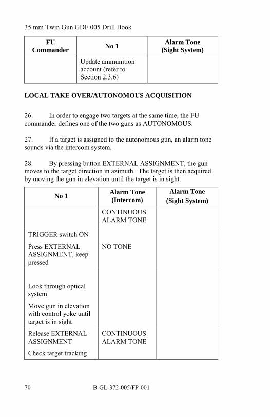
LOCAL TAKE OVER/AUTONOMOUS ACQUISITION
26. In order to engage two targets at the same time, the FUcommander defines one of the two guns as AUTONOMOUS.
27. If a target is assigned to the autonomous gun, an alarm tonesounds via the intercom system.
28. By pressing button EXTERNAL ASSIGNMENT, the gunmoves to the target direction in azimuth. The target is then acquiredby moving the gun in elevation until the target is in sight.
No 1 Alarm Tone(Intercom)
Alarm Tone(Sight System)
CONTINUOUSALARM TONE
TRIGGER switch ON
Press EXTERNALASSIGNMENT, keeppressed
NO TONE
Look through opticalsystem
Move gun in elevationwith control yoke untiltarget is in sight
Release EXTERNALASSIGNMENT
CONTINUOUSALARM TONE
Check target tracking

Standard Operating Procedures
B-GL-372-005/FP-001 71
No 1 Alarm Tone(Intercom)
Alarm Tone(Sight System)
Press buttonTRACKING brieflywhile pressing head rest NO TONE MEDIUM TONE
Perform visual IFF
Continue smoothtracking
Press FIRE SAFETYBAR LONG TONE
Press FIRE switchwhile keeping FIRESAFETY BARdepressed LONG TONE
Press buttonTRACKING twice toreturn to LOCAL
Close TRIGGERswitch
Report results ofengagement to FUCommander
If the alarm tonepersists startprocedure frombeginning
LOCAL ENGAGEMENT AIR TARGETS
No 5 No 1 Alarm Tone(Sight System)
"ATTENTIONAIR TARGET– FIVEMEDIUM"
Presslaser/triggerinterrupter ifsafetyprecautions are
TRIGGER switch ON
AMMUNITION switch toREST 10
Acquire target by means ofcollimator
Look through optical systemand press headrest
Keep target in centre ofreticule

35 mm Twin Gun GDF 005 Drill Book
B-GL-372-005/FP-00172
No 5 No 1 Alarm Tone(Sight System)
met
"ALARM NEWTARGET –TWOMEDIUM"
"ALL CLEAR"
Press TRACKING buttonbriefly
Continue smooth tracking(IFF)
Press FIRE SAFETY BAR
Press FIRE switch and keepFIRE SAFETY BAR pressed
Press TRACKING buttononce to return to trackingmode
Press TRACKING buttontwice to return to rest
Acquire target by means ofcollimator and proceed asdescribed above
Press TRACKING buttontwice to return to reset
Close TRIGGER switch
Go to standby
Update ammunition account(refer to Section 2.3.6)
NO TONE
MEDIUMTONE
LONG TONE
LONG TONE
MEDIUM/LONG TONE
NO TONE

Standard Operating Procedures
B-GL-372-005/FP-001 73
LOCAL ENGAGEMENT GROUND TARGETS
No 5 No 1Alarm Tone
(Sight System)
"ATTENTIONGROUNDTARGETS –FIVE LOW ...(target type)"
Presslaser/triggerinterrupter ifsafetyprecautions aremet
"ALARM NEWTARGET –TWO LOW ...(target type)"
TRIGGER switch ON
AMMUNITION switch toREST 10
Set NORMAL/NARROWswitch to NARROW
Acquire target by means ofcollimator
Look through optical systemand press headrest
Keep target in centre ofreticule
Press TRACKING buttonbriefly
Continue smooth tracking(IFF)
Press FIRE SAFETY BAR
Press FIRE switch and keepFIRE SAFETY BAR pressed
Press TRACKING buttononce to return to trackingmode
Press TRACKING buttontwice to return to rest
Acquire target by means ofcollimator and proceed asdescribed above
NO TONE
MEDIUMTONE
LONG TONE
LONG TONE
MEDIUM/LONG TONE
NO TONE

35 mm Twin Gun GDF 005 Drill Book
B-GL-372-005/FP-00174
No 5 No 1Alarm Tone
(Sight System)
Press TRACKING buttontwice to return to reset
Set NORMAL/NARROWswitch to NORMAL
Close TRIGGER switch
Go to standby
Update ammunition account(refer to Section 2.3.6)

Standard Operating Procedures
B-GL-372-005/FP-001 75
AUTOMATIC RELOADING/REFILL RELOADERS
NOTE
No 1 can initiate automatic reloading by pressing the AUTOMLOAD switch on the remote control unit. This procedure is alwayscarried out after firing and before refilling the reloaders.
No 1 No 2 (right) No 3 (left)
Ensure that TRIGGERswitch is at S
Press LOAD POSbutton
WARNING
Gun moves to loadingposition
Set the POWER switchto ON and back toSERVO
Lower the barrels toapproximately 0 mil
Set POWER switch toON
Engage the traverselock
"ENGAGED"
"REFILLRELOADERS"
Note how manycartridge clips were inreloaders
Move reloader toSP
Check red greaselevel button onALs
Refill reloader
Move reloader toWP
Move reloader toSP
Refill reloader
Move reloader toWP

35 mm Twin Gun GDF 005 Drill Book
B-GL-372-005/FP-00176
No 1 No 2 (right) No 3 (left)
"NO 2 READY ...CARTRIDGECLIPSLOADED"
"NO 3 READY ...CARTRIDGECLIPS LOADED"
Go outside limitedzone
Go outside limitedzone
Ensure no one is insidelimited zone
Disengage traverse lock
"DISENGAGED"
Set POWER switch toSERVO
Update the ammunitionaccount(refer to Section 2.3.6)
Bring gun to standby
UPDATE AMMUNITION ACCOUNT
No 1
MENU 6 Select Menu 6
RET
CHANGE DATA?
YES
SALVOTIM ...SEC
RET Press RET several times until AMMORELO+?MAG

Standard Operating Procedures
B-GL-372-005/FP-001 77
No 1
AMMORELO+?MAG
Enter number of cartridge clips loaded
RET To store value
AMMO RES ... RD
END
MENU 7
MENU 1 Select Menu 1
SECTION 5AFTER ENGAGEMENT
INTRODUCTION
29. This part deals with taking the gun out of action.
PREPARE TO MOVE
No 1 No 2 No 3 No 4 No 5
"PREPARETO MOVE"
Remove lowercamouflage net
Remove lowercamouflage net
Remove lowercamouflage net
NOTEIn certain situations, some elements of this part need not becarried out. These situations are covered in Section 2.6,Quick Action.

35 mm Twin Gun GDF 005 Drill Book
B-GL-372-005/FP-00178
No 1 No 2 No 3 No 4 No 5
Watch arcs Swing in uppercamouflage netand place ontarpaulin
Swing in uppercamouflage netand place ontarpaulin
Pack all extraammunition
NOTE
This drill can vary depending on the time remaining in action and isalso dependant on unit SOPs.
CEASE FIRING
No 1 No 2 No 3 No 4 No 5"UNLOAD" Unload
respectiveside
Unloadrespectiveside
Putammunitionin boxes
Putammunitionin boxes
Bring primemover topositionLoad allstores onprime moverincludingrefuellingdevice andfuel cans
Load allstores onprime moverincludingrefuellingdevice andfuel cans
"CEASEFIRING"Place barrelsover PSU
Reel in cabledrum
Reel in cabledrum
Replace sightcover
Removesafety fence
Removesafety fence
SetINSTALLswitch onPSU to LVLONLYSwitch onhydraulicpump

Standard Operating Procedures
B-GL-372-005/FP-001 79
No 1 No 2 No 3 No 4 No 5Push inFAST/SLOW leverLift gun
"UNLOCKWHEELS"
Unlockwheels
Unlockwheels
Unlockwheels
"UNLOCKED" "UNLOCKED"
Lowerwheels
"LOCKWHEELS"
Lock wheels Lock wheels Lock wheels
"LOCKED" "LOCKED"
Lower gun
INSTALLswitch toNORMAL
Replace fireextinguisher
Swing inswivel arm
Swing inswivel arm
Remove MVand replacewith muzzlebrakes
Remove MVand replacewith muzzlebrakes
Replacebarreltarpaulin
Raise andlock barrels
Replace frontundercarriagetarpaulin
Replace frontundercarriagetarpaulin

35 mm Twin Gun GDF 005 Drill Book
B-GL-372-005/FP-00180
No 1 No 2 No 3 No 4 No 5
Replace sighttarpaulin
Replacereloadertarpaulin
Replacereloadertarpaulin
Lowercollimator
Replace ALtarpaulin
Replace ALtarpaulin
Replace rearundercarriagetarpaulin
Replace rearundercarriagetarpaulin
Replace maintarpaulin
Replace maintarpaulin
Replace maintarpaulin
Guide primemover totowing hook
Free towbar(red pin)
Free towbar(red pin)
Back primemover to gunguided by No1
Lift Lift
Hook towbarinto towingeye
Hook towbarinto towingeye
Switch offPSU
Hook upbrake hoseyellow
Hook upbrake hosered
Hook upvehiclelighting cable
Release handbrake
Release handbrake
Raise PSU Replacewheel chock
Ensure stopcock lever isat FULLLOAD
Insert pumplever PSU
Roll downair outletcover
Lift slidelever

Standard Operating Procedures
B-GL-372-005/FP-001 81
No 1 No 2 No 3 No 4 No 5
Removelocking pin
Disengagerocking lever
Pump PSUup
Replacelocking pin
Replacepump lever
"MOUNT"
CHECK
Condition of tires
Rear hand brakes are unlocked
Stop cock lever is at FULLLOAD
Towbar is properly connected tothe prime mover
Brake couplings are properlyconnected
Lighting cable is properly connected
Tarpaulins are fitted correctly
Swivel arms are retracted andsecured
SECTION 6AUXILIARY OPERATION MODE
INTRODUCTION
30. The auxiliary operation mode allows the gun to be operatedwithout power from the PSU, for example, as a result of a breakdownof the PSU.
HALT—ACTION MANUAL
No 1 Nos 2 and 3
"HALT - ACTION MANUAL"
Uncover gun

35 mm Twin Gun GDF 005 Drill Book
B-GL-372-005/FP-00182
No 1 Nos 2 and 3
Lower PSU Apply park brakes
Move slide lever down Secure towbar
PSU is automatically lowered Swing out swivel arms and lock
Lower barrels Remove barrel cover
Remove muzzle covers
Remove protective cover onhand pump
Push in FAST/SLOW lever Take out hand pump lever
Set the three jack control leversto RAISE position
Insert hand pump lever
Set hand pump selection leverto the chosen jack
Lift gun
Lift gun until wheels are clearof the ground by raising eachjack individually
NOTE
No 4 and No 5 may assist inpumping.
Set the three jack control leversto NEUTRAL
Unlock front and rearundercarriage locking levers
Set wheel control lever toRAISE
Pump to tilt wheels
Ensure undercarriage locks areengaged
Set wheel control lever toNEUTRAL
"LEVELLING"

Standard Operating Procedures
B-GL-372-005/FP-001 83
No 1 Nos 2 and 3
Set the three jack control leversto LOWER position
Set hand pump selection leverto chosen jack
Lower gun to desired position
Pump to level gun
Set the three jack control leversto RAISE
Pull out FAST/SLOW lever toSLOW
Level gun using spirit level
(cross level = jack No 2/3
longitudinal level = jack No 1)
Set three jack control levers toNEUTRAL
Remove hand pump lever
Put on protective cover
Replace hand pump lever
Take out hand ratchets
READINESS CHECK—MANUAL
No 1 Nos 2 and 3
"READINESS CHECK—MANUAL"
Prepare the following data:
Terrain limitation
Standby Direction
Loading Position
Adjust seat
Set MOTOR/HAND levers toHAND

35 mm Twin Gun GDF 005 Drill Book
B-GL-372-005/FP-00184
No 1 Nos 2 and 3
Ensure that mechanical firinglever is at S
Ensure that laser/trigger footswitch is covered
Pump hydraulic pressure to 100bar
Ensure gas shield is in upposition
Engage collimator
Disengage traverse lock
"DISENGAGED"
"LOADING POSITION"
Indicate with an extended armposition of barrels
Turn barrels to positionmanually
"STANDBY"
Designate standby direction
Turn gun barrels to positionmanually
Designate alarm sectors

Standard Operating Procedures
B-GL-372-005/FP-001 85
FIRE TRIGGER CHECK—MANUAL
No 1 Nos 2 and 3
"ATTENTION FIRE TRIGGERCHECK—MANUAL"
Stay behind gun, outside limitedzone
"GUN 1 (2) FIRE TRIGGERCHECK"
Ensure that weapons are not fed
Check hydraulic pressure onpressure gauge reads at least 80bar
Set mechanical firing lever to F
Open cover over laser/triggerfoot switch
Press down laser/trigger footswitch
"GUN 1 (2) TRIGGERS AREOK"
Cover laser/trigger foot switch
Set mechanical firing lever to S
"TRIGGER CHECKFINISHED"
Turn barrels to standby direction

35 mm Twin Gun GDF 005 Drill Book
B-GL-372-005/FP-00186
LOADING—MANUAL
No 1 Nos 2 and 3
"LOADING—MANUAL"
"LOADING POSITION"
Turn gun to loading position Take ratchet
Ensure laser/trigger foot switchis covered
Ensure mechanical firing lever isat S
Engage traverse lock
"ENGAGED" Move reloader to SP and lock
Ensure that discharge lever is inposition IM
Ensure an empty cartridge clip isin AL
Load full cartridge clips
Cock weapon
Release cocking cables
Fix hand ratchet onto shaft ofratchet drive on outside of AL
Transport ammunition toweapon mouth with hand ratchet
Observe transport and feeding
Wind spring motor to stop
WARNINGTo avoid an accident, the handratchet must be removed.Remove hand ratchetAdd two more full cartridgeclips

Standard Operating Procedures
B-GL-372-005/FP-001 87
No 1 Nos 2 and 3Report loaded and fed
"LOADED AND FED"Go outside limited zone of gun
Ensure that no one is insidelimited zone of the gunDisengage traverse lock"DISENGAGED"Turn barrels to standby direction
STANDBY—MANUAL
No 1 Nos 2 and 3
"STAND BY" Move to rear of standby position
Turn barrels to standby directionmanually (elevationapproximately 0-200 mil)
Ensure that:TRIGGER switch on remotecontrol unit is coveredMechanical firing lever is at S
Laser/trigger foot switch iscovered
Switches on control panel:AMMUNINTION switch onREST 3All other switches are in upposition (ON)
NORMAL/NARROW switchat NORMAL
NORMAL/TEST switch atNORMAL
WIPER switch is OFF
RANGE switch is at LASER
Gas shield is in up position
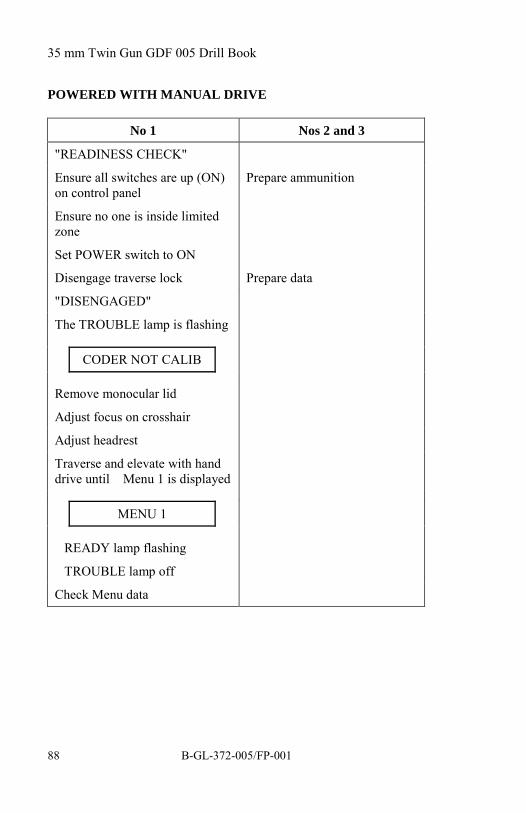
35 mm Twin Gun GDF 005 Drill Book
B-GL-372-005/FP-00188
POWERED WITH MANUAL DRIVE
No 1 Nos 2 and 3
"READINESS CHECK"
Ensure all switches are up (ON)on control panel
Prepare ammunition
Ensure no one is inside limitedzone
Set POWER switch to ON
Disengage traverse lock Prepare data
"DISENGAGED"
The TROUBLE lamp is flashing
CODER NOT CALIB
Remove monocular lid
Adjust focus on crosshair
Adjust headrest
Traverse and elevate with handdrive until Menu 1 is displayed
MENU 1
READY lamp flashing
TROUBLE lamp off
Check Menu data

Standard Operating Procedures
B-GL-372-005/FP-001 89
FIRING WITH LASER
No 5 No 1 Alarm Tone
"ALARM—FIVEMEDIUM"
Set mechanicalfiring lever at F
Open laser/triggercover
Acquire target withcollimator
Look through opticalsight and pressheadrest NO TONE
Keep target in centreof reticule
Press laser/triggerfoot switch (lasermeasuring) MEDIUM TONE
Continue trackingand follow by hand(IFF) LONG TONE
"ALARM—NEWTARGET—TWOMEDIUM"
Turn gun in ordereddirection, usingmanual drive
Acquire target withcollimator andproceed as describedabove
Close laser/triggercover
Set mechanicalfiring lever at S
Reload gun

35 mm Twin Gun GDF 005 Drill Book
B-GL-372-005/FP-00190
FIRING WITH FIXED DISTANCE
No 5 No 1
"ALARM—FIVE MEDIUM—RANGE SHORT"
Set mechanical firing lever at F
Open laser/trigger cover
Set RANGE switch to SHORT
Acquire target with collimator
Keep target in centre reticule
Continue tracking by hand (IFF)
Press down laser/trigger footswitch
Stand by
"ALARM—NEW TARGET—TWO MEDIUM RANGELONG"
Open laser/trigger cover
Set RANGE switch to LONG
Acquire target with collimatorand proceed as described above
FIRING WITHOUT POWER
No 5 No 1
"ALARM—FIVE MEDIUM"
Set mechanical firing lever to F
Open laser/trigger cover
Acquire target with collimator

Standard Operating Procedures
B-GL-372-005/FP-001 91
No 5 No 1
Keep target in centre circle ofcollimator, take into accountballistic conditions
Press down laser/trigger footswitch for a short burst
Make corrections with manualdrive
Press down laser/trigger footswitch for another short burst
Cover laser/trigger foot switch
Set mechanical firing lever to S
RELOADING—MANUAL
No 1 No 2 No 3
"RELOAD" Go inside limited zone of the gun
Check hydraulicpressure formechanical trigger(100 bar)
Wind up spring motors with ratchet (ifnecessary)
Remove ratchet
Refill ALs with ammunition from reloader
"2 RELOADED—CARTRIDGECLIPS"
"3 RELOADED—CARTRIDGECLIPS"
Go outside limited zone
Note down numberof cartridge clipsloaded

35 mm Twin Gun GDF 005 Drill Book
B-GL-372-005/FP-00192
No 1 No 2 No 3
Updateammunitionaccount if possible
Return to standby
CEASE FIRING—MANUAL
No 1 Nos 2 and 3 Nos 4 and 5
"CEASE FIRING—MANUAL"
Inform Nos 4 and 5
Engage traverse lock
"ENGAGED"
Ensure mechanicalfiring lever is at S
Remove MV bases
Ensure laser/triggerfoot switch is covered
Fit muzzle brakes
Lock barrels Load stores
Set the three jackcontrol levers toRAISE
Remove hand pumplever from toolcompartment
Set FAST/SLOWcontrol to FAST
Remove protectivecover on hand pump
Attach hand pump lever
Set hand pumpselection lever to thechosen jack
Set the three jackcontrol levers toNEUTRAL
Lift gun
Set wheel controllever to RAISEbriefly (two pumps)
Pump twice
Pull out

Standard Operating Procedures
B-GL-372-005/FP-001 93
No 1 Nos 2 and 3 Nos 4 and 5undercarriage lockinglevers and turnhandles through 90°
No 1 No’s 2 and 3
Set wheel control lever toLOWER
Lower wheels
Secure undercarriage lockinglevers (yellow on yellow)
Set wheel control lever toNEUTRAL
Set the three jack control leversto DOWN
Set hand pump selection lever tothe chosen jack—lower gun andretract jacks completely
Set the three jack control leversto NEUTRAL
Remove hand pump lever toPSU lifting device
Remove hand pump lever
Insert pump lever Put hand pump lever in toolcompartment—fit protectivecover
Remove locking pin
Lift slide lever
Pump to lift the PSU completely Swing in swivel arms
Re-insert locking pin Secure safety ropes
Move slide lever down Bring reloaders to WP
Replace pump lever Release brake levers
Release towbar
Complete Cease Firing as inSection 2.4.3

35 mm Twin Gun GDF 005 Drill Book
B-GL-372-005/FP-00194
SECTION 7QUICK ACTION
INTRODUCTION
31. This section deals with both electrically supported andmanual quick action. Quick actions are drills used to prepare the gunfor imminent combat while travelling in convoy. When moving fromone position to another the gun may be prepared as follows:
a. gun not covered (environmental conditionspermitting);
b. muzzle velocity bases on;
c. PSU lowered and running at 2200 r/min; and
d. ammunition feeders and reloaders full.
32. The FU Commander orders the degree of preparedness.
QUICK ACTION, ELECTRICALLY SUPPORTED
No 1 Nos 2 and 3 Nos 4 and 5
"HALT—ACTION,ACTION, ACTION"
Stop prime mover
Jump off primemover
Jump off primemover
Lower barrel support Disconnect brakehoses
Lower barrels Disconnect towbarand lights
Switch INSTALLswitch to LVL
Ensure reloaders inSP and loaded
Drive to shelter

Standard Operating Procedures
B-GL-372-005/FP-001 95
No 1 Nos 2 and 3 Nos 4 and 5
Start hydraulic pump Swing out and lockswivel arms
Raise gun untilwheels clear ground
Stop hydraulic pump Cock weapons
Set FAST/SLOWcontrol lever toSLOW
Ensure reloaders areat WP
Set INSTALLswitch to NORMAL
Take cover nearby
Set PSU main switchto operation
No 1
All switches on control panel are up (ON) except RELOADINGSYSTEM LEFT/RIGHT at OFF
Set POWER switch to SERVO
CODER NOT CALIB
Disengage traverse lock
"DISENGAGED"
MENU 1
RET
DRIFT TRIM
MENU 2
MENU 6 Select Menu 6
RET
CHANGE DATA?

35 mm Twin Gun GDF 005 Drill Book
B-GL-372-005/FP-00196
No 1
YES
SALVOTIM ... SEC
Enter 0.5
RET
END
Engage target
MANUAL QUICK ACTION
No 1 Nos 2 and 3 Nos 4 and 5
"HALT —ACTION, ACTION,ACTION"
Stop prime mover
Jump off primemover
Jump off primemover
Remove cable rolls Disconnect brakehoses
Disconnect towbarand lights
Help remove maintarpaulin at rear
Remove maintarpaulin at front
Drive to shelter
Lower barrel support Ensure reloaders inSP
Lower barrels Swing out swivelarms
Insert wheel chock
Climb in gunner'scabin
Cock weapons

Standard Operating Procedures
B-GL-372-005/FP-001 97
No 1 Nos 2 and 3 Nos 4 and 5
Assemble ratchetsand insert in AL
Feed weapons
Remove ratchets
Set FIRE/SAFElever to FIRE
Take cover nearby
Open laser/triggerfoot switch cover
Ensure minimum 80bar pressure inhydraulic system
Disengage traverselock
"DISENGAGE"
Engage target usingcollimator andmanual drive
No 1 Nos 2 and 3
After second burst command
"FEED" Go to gun and insert ratchets inAL
Wind up spring motors
Remove ratchets
"FED"
Re-engage target
Take cover nearby
NOTE
Continue above procedure until "ALERT STATE CHANGED".Then unload and re-establish previous travelling configuration.

35 mm Twin Gun GDF 005 Drill Book
B-GL-372-005/FP-00198
SECTION 8PREPARE GUN FOR TRAINING SIMULATOR 2
33. Prerequisites:
a. Unload the gun.
b. Connect gun to the Training Simulator (TS) 2according to the TS 2 manual Operation and Care(refer to C-79-207-000/MB-001).
c. Install the Video Presentation Unit (VPU) accordingto the TS 2 manual Operation and Care (refer to C-79-207-000/MB-001).
TS 2 Operator No 1
Select Menu 5ALIGNMENT"PREPARE GUN1(2)(3)(4) FOR TS 2OPERATION"
"PREPARE GUN 1(2)(3)(4) FOR TS 2OPERATION"
Verify position of VPU (videopresentation unit) main switch = ON(fully counter clockwise)
Verify all four LEDs on VPU are on
MENU 23
RET
TRAINING MODE = 0
Enter 1
RET

Standard Operating Procedures
B-GL-372-005/FP-001 99
TS 2 Operator No 1
CALIB LEFT?
If the TS 2 crosshair is to the left of thereticule, press YES until aligned.
RET
CALIB RIGHT?
If the TS 2 crosshair is to the right ofthe reticule, press YES until aligned.
RET
CALIB UP?
If the TS 2 crosshair is higher than thereticule, press YES until aligned.
RET
CALIB DOWN?
If the TS 2 crosshair is lower than thereticule, press YES until aligned.
Verify crosshairs aligned (if notaligned, press RET and start procedureat CALIB_LEFT? again).
END
Switch conveyor motors OFFSet trigger switch to FIRESet range switch to LASERSet laser sector to maximum (fully open)Set fire sector to maximum (fully open)"GUN 1(2)(3)(4) READY"


35 mm Twin Gun GDF 005 Drill Book
B-GL-372-005/FP-001 101
CHAPTER 3RANGE OPERATIONS
SECTION 1RANGE FIRING
1. This part of B-GL-372-005/FP-001 35 mm Twin GunGDF 005 Drill Book deals with the specific safety measures applicablewhen the fire unit is deployed on a firing range. Unless otherwisementioned, the regular procedures apply. Deployment on a firingrange involves additional personnel and equipment.
INTRODUCTION
2. The Range Safety Officer (RSO) is responsible to the Officerin Charge (OIC) for the safe conduct of a Gun/Skyguard live firingpractice. If more than one firing point (FP) is in use, a Firing PointOfficer (FPO) is required for each firing point. Each FPO isresponsible to the RSO for the safe conduct at his respective FP.
3. No Skyguard or gun will be operated on the range without theproper laser attenuation filter installed. Values are: Skyguard 30dB/Gun 20 dB. It is the RSO's responsibility to ensure that thesefilters are in place prior to the commencement of the practice.
4. Range practice shall be conducted in accordance with RangeStanding Orders and CFP 304(3). Specific instructions for rangesafety are provided in these publications. Individual responsibilities ofthe RSO, FPO and other range personnel are described in detail inthese publications.

35 mm Twin Gun GDF 005 Drill Book
B-GL-372-005/FP-001102
SYSTEMATIC SEQUENCE FOR PREPARATION OF THEFIRE UNIT
FCU GUN SAFETY
Preparation ofFCU
Preparation ofGun
Preparation/ Integration of FU
Connection of FireControl and SelectSystem (FCSS) andLaser andFire EnableSwitchesSwitch FCSS onSet all FIREToggle Switches toON
Store FictitiousTarget Point
Store Laser/FireSectors
StoreLaser/Fire/
Servo Sectors
Meteo Evaluation MaintenanceBefore Firing
Report MeteoData
Input MeteoData
RSO Checks all Laser/Fire/Servo Sectors
Conduct Laser/Fire Trigger and Safety Checks
Loading
AmmunitionAccount
Fictitious Target Firing
FIRE UNIT READY FOR RANGE FIRING
Figure 3-1: Systematic Sequence for Preparation of the Fire Unit

Range Operations
B-GL-372-005/FP-001 103
SECTION 2DUTIES OF NUMBER 1
BEFORE FIRING
5. The Number 1 crew member on each of the gun will ensurethat:
a. the firing window and sector limitations have beenset on the gun;
b. the safety fence and fire extinguisher are correctly inplace;
c. the standby direction is clearly identified;
d. the reload position is opposite to the standbydirection;
e. the remote control unit is properly connected to theupper mount;
f. the weapon top covers and weapon protective coverare properly closed and secured; and
g. the laser safety template is in place.
DURING FIRING
6. Number 1 will ensure that a gun crew member will remainseated on the gun during local and remote engagements. Tracking willcommence when the order "FIRING RUN" is received and the targetis within the range safety arcs. Laser and trigger operation will beallowed once the Weapon Safety Officer (WSO) and Laser SafetySupervisor (LSS) have ensured that all safety measures have been met.Number 1 will cease firing if:
a. the FPO, RSO or WSO orders "CHECK FIRING";

35 mm Twin Gun GDF 005 Drill Book
B-GL-372-005/FP-001104
b. an aircraft (other than the towing aircraft) is reportedin or near the range safety arcs;
c. a vessel on an over-water range enters the rangesafety arcs;
d. a target is damaged and has difficulty flying;
e. range safety communication fails; or
f. for any other reason deemed unsafe for firing tocontinue.
SECTION 3DUTIES OF WEAPON SAFETY OFFICER/LASER SAFETY
SUPERVISOR
BEFORE FIRING
7. Prior to firing each WSO, assisted by the LSS whereapplicable, will ensure that:
a. the firing window and sector limitations are properlyset on the gun;
b. the arc markers behind the gun are properlypositioned;
c. the safety fence and fire extinguisher are correctly inplace;
d. the laser safety place on the gun is set to blue at alltimes;
e. the laser safety plate on each gun is in place; and
f. the laser enable switch and the fire enable switch arecorrectly connected and a red flag is available.

Range Operations
B-GL-372-005/FP-001 105
DURING FIRING
8. During firing, each WSO (assisted by the LSS whereapplicable) will remain behind the gun at all times holding the laserenable switch. When the target is within the respective sector, theWSO/LSS will press the laser enable switch and the fire enable switchas applicable and will release it if:
a. the FPO or RSO orders "CHECK FIRING";
b. Number 1 is tracking the aircraft, if a towed sleeveis being used;
c. an aircraft (other than the towing aircraft) is reportedon or near the range safety arcs;
d. the target is outside of the arcs or obscured byclouds;
e. range safety communication fails;
f. a stoppage or misfire occurs; or
g. for any other reason deemed unsafe for firing tocontinue.
AFTER FIRING
9. After firing, each WSO (assisted by the LSS whereapplicable) will ensure that:
a. the gun is aimed in a safe direction and that allammunition has been removed from the weapon;
b. the laser enable switch and fire enable switch areunlocked; and
c. the safety fence remains in place until the barrelshave been locked.

35 mm Twin Gun GDF 005 Drill Book
B-GL-372-005/FP-001106
10. Once completed, the WSO will report to the FPO"WEAPONS CLEAR".
FIRE CONTROL AND SELECT SYSTEM
11. The Fire Control and Select System (FCSS) gives the RSOcomplete control to "ENABLE" or "DISABLE" every laser or firesignal on the range. The activation of the power switch will force"CHECK FIRING" for the whole range in a matter of seconds. Eachlaser or fire signal can be handled individually.
12. The FCSS is installed and connected by a qualified RangeEquipment Operator (REO).
13. The fire enable switch and the laser enable switch operatedby the WSO and LSS are part of the FCSS.
COMMUNICATION AND INTERCOM SYSTEM
14. The Communication and Intercom System (CIS) provides theRSO with all necessary communication links required to control theFP.
15. Communication links available are:
a. one way communication (listening) to all connectedfire units;
b. two way communication between CIS and selectedFCUs and guns;
c. loudspeakers for announcements to all personnel onthe firing point(s); and
d. an override intercom station (voice request) forrange safety.
16. The CIS is installed and connected by a qualified REO.

Range Operations
B-GL-372-005/FP-001 107
VIDEO EVALUATION SYSTEM
17. The Video Evaluation System (VES) is used primarily toevaluate the live ammunition firing results of the gun and theSkyguard operators against live targets. A secondary role is to providethe RSO with real time information about the target currently trackedby the Skyguard and guns. The RSO will only enable firing (using theFCSS) if the correct target is being tracked by the Skyguard and guns.
18. The VES is installed, connected and operated by a qualifiedREO.
SECTION 4SAFETY SECTORS
LASER SECTOR
19. Use of the laser is permitted within the laser sector (seeFigure 3-2). The laser sector is set using Menu 3. The sector isalways larger than that of the fire sector.
FIRE SECTOR
20. Firing is only permitted within the fire sector (seeFigure 3-2), allowing a safety margin of 100 mils for deviations ofshell trajectory. The fire sector is set using Menu 4.
SERVO SECTOR
21. The servo sector is designed to restrict the electricalmovement of the gun in elevation and traverse. It is set and activatedusing Menu 10 once the guns are loaded.

35 mm Twin Gun GDF 005 Drill Book
B-GL-372-005/FP-001108
SAFETY SECTORS
Fire Sector 1a - 2a - 3a - 4a
Laser Sector 1b - 2b - 3b - 4b
Servo Sector LIM LEFT - LIM RIGHT - LIM HIGH - LIM LOW
Figure 3-2: Fire, Laser and Servo Sectors
SET LASER SECTOR
RSO No 1
"SET LASERSECTOR"
Set POWER switch to ON
Set MOTOR/HAND levers to HAND
MENU 3Ensure that Menu 3 isselected
RET
LSECT CHECK?
RET

Range Operations
B-GL-372-005/FP-001 109
RSO No 1
LSECT PROC?
YES
AzimuthElevation 1
Current position isdisplayed.
"READY"
"POINT 1:AzimuthElevation"
Move gun until corresponding values appear
AzimuthElevation 1
RET
"POINT 1 SET"
"POINT 2:AzimuthElevation"
Move gun until corresponding values appear
AzimuthElevation 2
RET
"POINT 2 SET"
"POINT 3:AzimuthElevation"
Move gun until corresponding values appear
AzimuthElevation 3
RET
"POINT 3 SET"
"POINT 4:AzimuthElevation"
Move gun until corresponding values appear

35 mm Twin Gun GDF 005 Drill Book
B-GL-372-005/FP-001110
RSO No 1Azimuth
Elevation 4
RET
"POINT 4 SET"
END Leave menu when requiredpoints have been selected.
The last point stored isautomatically linked to the first.
MENU 4
"LASER SECTOR SET"
SET FIRE SECTOR
RSO No 1
"SET FIRESECTOR"
Set POWER switch to ON
Set MOTOR/HAND levers to HAND
MENU 4 Ensure Menu 4 isselected.
RET
FSECT CHECK?
RET
FSECT PROC?
YES
AzimuthElevation 1
Current position isdisplayed
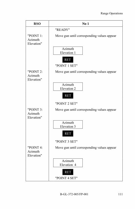
Range Operations
B-GL-372-005/FP-001 111
RSO No 1
"READY"
"POINT 1:AzimuthElevation"
Move gun until corresponding values appear
AzimuthElevation 1
RET
"POINT 1 SET"
"POINT 2:AzimuthElevation"
Move gun until corresponding values appear
AzimuthElevation 2
RET
"POINT 2 SET"
"POINT 3:AzimuthElevation"
Move gun until corresponding values appear
AzimuthElevation 3
RET
"POINT 3 SET"
"POINT 4:AzimuthElevation"
Move gun until corresponding values appear
AzimuthElevation 4
RET
"POINT 4 SET"

35 mm Twin Gun GDF 005 Drill Book
B-GL-372-005/FP-001112
RSO No 1
END
MENU 5
"FIRESECTORSET"
Leave menu whenrequired points have beenselected.
The last point stored isautomatically linked tothe first.
SET SERVO SECTOR
NOTE
LIM - HIGH is normally maximum elevation in order to permitautomatic reloading (1600 mils). To obtain the safety for the upperlimit, a technician can set the Mechanical Fire Sector Limiter.
RSO No 1
"SETSERVOSECTOR"
Set POWER switch to ON
Set MOTOR/HAND levers to HAND
MENU 10 Select Menu 10
RET
SECT LIMMOUNT
1 Activates servo sector.
RET
SECT LIMCHECK?
RET

Range Operations
B-GL-372-005/FP-001 113
RSO No 1SECT LIM
PROC?
YES
"READY"
"LEFTLIMIT: ....mil"
Move gun until corresponding value appears
LIM_LEFT(Azimuth)
RET
"LEFT LIMIT SET"
"RIGHTLIMIT: ....mil"
Move gun until corresponding value appears
LIM_RIGHT(Azimuth)
RET
"RIGHT LIMIT SET"
"LIMITHIGH: ....mil"
Move gun until corresponding value appears
LIM_HIGH(Elevation)
RET
"LIMIT HIGH SET"
"LIMITLOW: ....mil"
Move gun until corresponding value appears
LIM_LOW(Elevation)
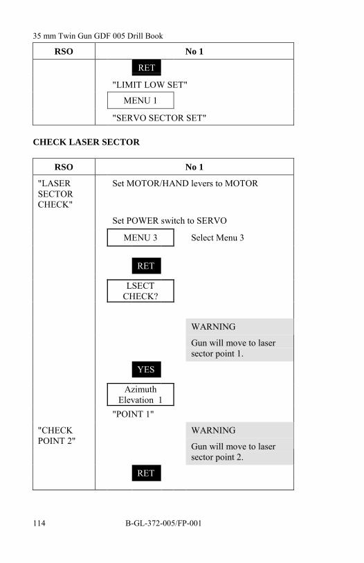
35 mm Twin Gun GDF 005 Drill Book
B-GL-372-005/FP-001114
RSO No 1
RET
"LIMIT LOW SET"
MENU 1
"SERVO SECTOR SET"
CHECK LASER SECTOR
RSO No 1
"LASERSECTORCHECK"
Set MOTOR/HAND levers to MOTOR
Set POWER switch to SERVO
MENU 3 Select Menu 3
RET
LSECTCHECK?
WARNING
Gun will move to lasersector point 1.
YES
AzimuthElevation 1
"POINT 1"
"CHECKPOINT 2"
WARNING
Gun will move to lasersector point 2.
RET

Range Operations
B-GL-372-005/FP-001 115
RSO No 1Azimuth
Elevation 2"POINT 2"
"CHECKPOINT 3"
WARNING
Gun will move to lasersector point 3.
RET
AzimuthElevation 3
"POINT 3"
"CHECKPOINT 4"
WARNING
Gun will move to lasersector point 4.
RET
AzimuthElevation 4
"POINT 4"
END Leave Menu 3 when allpoints have been checked.
MENU 4
"LASER SECTOR CHECK FINISHED"
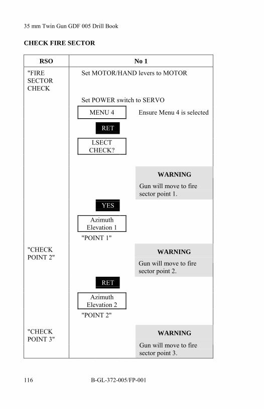
35 mm Twin Gun GDF 005 Drill Book
B-GL-372-005/FP-001116
CHECK FIRE SECTOR
RSO No 1
"FIRESECTORCHECK
Set MOTOR/HAND levers to MOTOR
Set POWER switch to SERVO
MENU 4 Ensure Menu 4 is selected
RET
LSECTCHECK?
WARNING
Gun will move to firesector point 1.
YES
AzimuthElevation 1
"POINT 1"
"CHECKPOINT 2"
WARNING
Gun will move to firesector point 2.
RET
AzimuthElevation 2
"POINT 2"
"CHECKPOINT 3"
WARNING
Gun will move to firesector point 3.

Range Operations
B-GL-372-005/FP-001 117
RSO No 1
RET
AzimuthElevation 3
"POINT 3"
"CHECKPOINT 4"
WARNING
Gun will move to firesector point 4.
RET
AzimuthElevation 4
"POINT 4"
END Leave Menu 4 when allpoints have been checked.
MENU 5
"FIRE SECTOR CHECK FINISHED"

35 mm Twin Gun GDF 005 Drill Book
B-GL-372-005/FP-001118
CHECK SERVO SECTOR
NOTE
1. Two methods are available to check the servo sector:
a. Check for the set value. The procedure is as forthe fire sector but using MENU 10 instead ofMENU 4.
b. The method given in this book includes afunctional check of the limiters. By driving thegun into the set limiters, correct setting of the stopscan be verified.
RSO No 1
"CHECKSERVOSECTOR"
Set MOTOR/HAND levers to MOTOR
Set POWER switch to SERVO
"READY"
"CHECKLEFT LIMIT"
WARNING
Gun will stop suddenly.
Check limitwith compass
Slew barrels to the left until stopped by sectorlimiter and wait.
"CHECKRIGHTLIMIT"
WARNING
Gun will stop suddenly.

Range Operations
B-GL-372-005/FP-001 119
RSO No 1
Check limitwith compass
Slew barrels to the right until stopped by sectorlimiter and wait.
"CHECKLOWERLIMIT"
WARNING
Gun will stop suddenly.
Lower barrels until stopped by sector limiter andwait.
Check limitvisually)
(if set)"CHECKUPPERLIMIT"
WARNING
Gun will stop suddenly.
Check limitvisually
Raise barrels until stopped by sector limiter andwait.
"SERVOSECTORCHECKFINISHED"
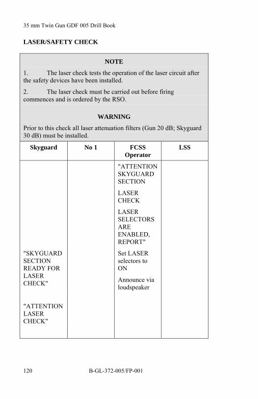
35 mm Twin Gun GDF 005 Drill Book
B-GL-372-005/FP-001120
LASER/SAFETY CHECK
NOTE
1. The laser check tests the operation of the laser circuit afterthe safety devices have been installed.
2. The laser check must be carried out before firingcommences and is ordered by the RSO.
WARNING
Prior to this check all laser attenuation filters (Gun 20 dB; Skyguard30 dB) must be installed.
Skyguard No 1 FCSSOperator
LSS
"ATTENTIONSKYGUARDSECTION
LASERCHECK
LASERSELECTORSAREENABLED,REPORT"
"SKYGUARDSECTIONREADY FORLASERCHECK"
"ATTENTIONLASERCHECK"
Set LASERselectors toON
Announce vialoudspeaker

Range Operations
B-GL-372-005/FP-001 121
Skyguard No 1 FCSSOperator
LSS
"GUN 1(2)LASERCHECK"
"ATTENTIONLSS LASERCHECK"
EnsureNORMAL/TEST lever isat NORMAL
EnsureNORMAL/NARROWlever is atNORMAL
EnsureRANGEswitch is atLASER
Set POWERswitch toSERVO
Move barrelsinto lasersector
When barrelspoint into lasersector presslaser enableswitch
Pressperiscopeheadrest withforehead

35 mm Twin Gun GDF 005 Drill Book
B-GL-372-005/FP-001122
Skyguard No 1 FCSSOperator
LSS
PressTRACKINGbutton
Listen to thelaser firingand themediumlength bleeps
Report toSkyguard
“GUN 1(2)LASER OK(NOT OK)”
Advise FCSSoperator ofresult of LaserCheck
If Laser Checkwas OK
Set toggleswitchesLASER toOFF
"SAFETYCHECK,LASERSELECTORSAREDISABLED"
Announce vialoudspeaker
"SKYGUARDSECTIONSAFETYCHECK"
"SAFETYCHECK"
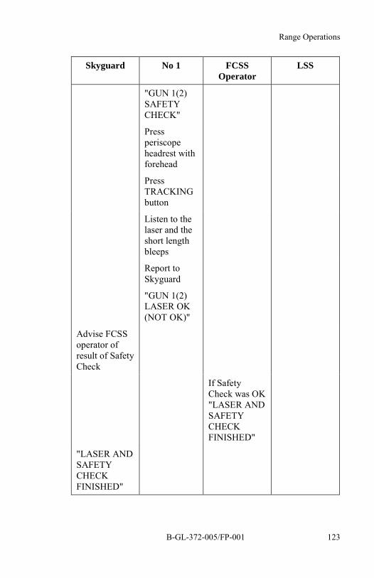
Range Operations
B-GL-372-005/FP-001 123
Skyguard No 1 FCSSOperator
LSS
"GUN 1(2)SAFETYCHECK"
Pressperiscopeheadrest withforehead
PressTRACKINGbutton
Listen to thelaser and theshort lengthbleeps
Report toSkyguard
"GUN 1(2)LASER OK(NOT OK)"
Advise FCSSoperator ofresult of SafetyCheck
If SafetyCheck was OK"LASER ANDSAFETYCHECKFINISHED"
"LASER ANDSAFETYCHECKFINISHED"

35 mm Twin Gun GDF 005 Drill Book
B-GL-372-005/FP-001124
Skyguard No 1 FCSSOperator
LSS
"GUN 1(2)LASER ANDSAFETYCHECKFINISHED"
Announce vialoudspeaker
"LASER ANDSAFETYCHECKFINISHED"
Release laserenable switch
Point barrelsto standbydirection
FIRE TRIGGER/SAFETY CHECK
NOTE
The fire trigger check tests the operation of the trigger circuit aftersafety devices have been installed. The fire trigger check must becarried out before any ammunition is loaded and is ordered by theRSO.
Skyguard No 1 FCSSOperator
LSS
"ATTENTIONFIRE UNITFIRETRIGGERCHECK FIRESELECTORSATENABLED,REPORT"
"FIRE UNITREADY FORFIRETRIGGERCHECK"

Range Operations
B-GL-372-005/FP-001 125
Skyguard No 1 FCSSOperator
LSS
Set FIREselectors toON
Announce vialoudspeaker
"ATTENTIONFIRETRIGGERCHECK
"GUN 1(2)FIRETRIGGERCHECK"
"ATTENTIONWSO FIRETRIGGERCHECK"
SetAMMUNITION switchesto REST 3
Set Conveyormotorswitches toON
Set triggerswitch onremotecontrol unit toF
Report toSkyguard
"GUN 1(2)READY"
Press ALARMGUN once
WARNING
Gun will move to fixed point
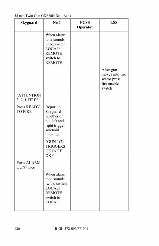
35 mm Twin Gun GDF 005 Drill Book
B-GL-372-005/FP-001126
Skyguard No 1 FCSSOperator
LSS
When alarmtone soundsonce, switchLOCAL/REMOTEswitch toREMOTE
After gunmoves into firesector pressfire enableswitch
"ATTENTION3, 2, 1 FIRE"
Press READYTO FIRE
Report toSkyguardwhether ornot left andright triggersolenoidoperated
"GUN 1(2)TRIGGERSOK (NOTOK)"
Press ALARMGUN twice
When alarmtone soundstwice, switchLOCAL/REMOTEswitch toLOCAL

Range Operations
B-GL-372-005/FP-001 127
Skyguard No 1 FCSSOperator
LSS
When alarmsounds twicerelease fireenable
Advise FCSSoperator ofresult of FireTrigger Check
If Fire TriggerCheck was OK
Set toggleswitches FIREto OFF
"SAFETYCHECK, FIRESELECTORSAREDISABLED"
Announce vialoudspeaker"SAFETYCHECK"
"SKYGUARDSECTIONSAFETYCHECK"
"GUN 1(2)SAFETYCHECK"
Press ALARMGUN once
WARNING
Gun will move to fixed point

35 mm Twin Gun GDF 005 Drill Book
B-GL-372-005/FP-001128
Skyguard No 1 FCSSOperator
LSS
When alarmtone soundsonce, switchLOCAL/REMOTEswitch toREMOTE
After gunmoves into firesector pressfire enableswitch
"SAFETYCHECK 3, 2,1 FIRE"
Press READYTO FIRE
Report toSkyguardwhether ornot left andright triggersolenoidoperated
"GUN 1(2)TRIGGERSOK (NOTOK)"
Press ALARMGUN twice
When alarmtone soundstwice, switchLOCAL/REMOTEswitch toLOCAL
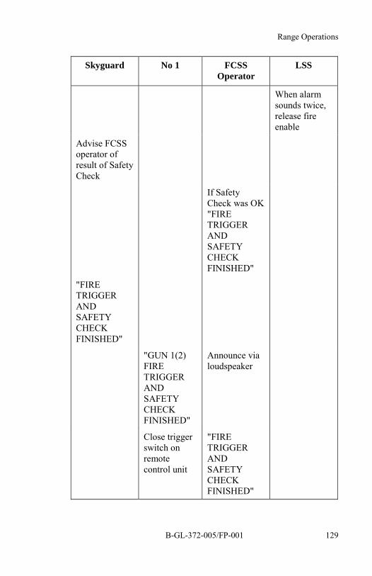
Range Operations
B-GL-372-005/FP-001 129
Skyguard No 1 FCSSOperator
LSS
When alarmsounds twice,release fireenable
Advise FCSSoperator ofresult of SafetyCheck
If SafetyCheck was OK"FIRETRIGGERANDSAFETYCHECKFINISHED"
"FIRETRIGGERANDSAFETYCHECKFINISHED"
"GUN 1(2)FIRETRIGGERANDSAFETYCHECKFINISHED"
Announce vialoudspeaker
Close triggerswitch onremotecontrol unit
"FIRETRIGGERANDSAFETYCHECKFINISHED"

35 mm Twin Gun GDF 005 Drill Book
B-GL-372-005/FP-001130
Skyguard No 1 FCSSOperator
LSS
Point barrelsto standbydirection

35 mm Twin Gun GDF 005 Drill Book
B-GL-372-005/FP-001 131
CHAPTER 4MAINTENANCE AND CARE
SECTION 1CRADLE LOCKING PROCEDURE
No 1 No 5
“LOCKING THE CRADLE” set the bearing and elevationchange over lever to manualoperation,
traverse the gun to themaintenance sector designatedby the No 1,
lock the bearing drive handle,and
depress the barrels to theirminimum elevation (approx 142mils).
Pull out the cradle handle andturn it ¼ turn until the handle isin vertical position,
Release the handle and push onit to ensure there is no gapbetween the cradle handle rodreceptacle.
“CRADLE LOCKED”
Move to the front of the barrelsand raise the barrels until theystop (approx 0 mils elevation);confirm barrels are locked bytrying to force travels upward. Ifthey do not go past 0 milselevation, they are locked, and
Maintain upward pressure andorder:

35 mm Twin Gun GDF 005 Drill Book
B-GL-372-005/FP-001132
No 1 No 5
“LOCK THE ELEVATIONDRIVE HANDLE”
Locks the elevation drive handleand reports:
“ELEVATION DRIVEHANDLE LOCKED”
Release upward pressure on thebarrels and supervises completeand prescribed maintenance.
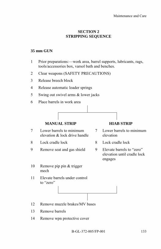
Maintenance and Care
B-GL-372-005/FP-001 133
SECTION 2STRIPPING SEQUENCE
35 mm GUN
1 Prior preparations:—work area, barrel supports, lubricants, rags,tools/accessories box, varsol bath and benches.
2 Clear weapons (SAFETY PRECAUTIONS)
3 Release breech block
4 Release automatic loader springs
5 Swing out swivel arms & lower jacks
6 Place barrels in work area
MANUAL STRIP HIAB STRIP
7 Lower barrels to minimumelevation & lock drive handle
7 Lower barrels to minimumelevation
8 Lock cradle lock 8 Lock cradle lock
9 Remove seat and gas shield 9 Elevate barrels to “zero”elevation until cradle lockengages
10 Remove pip pin & triggermech
11 Elevate barrels under controlto “zero”
12 Remove muzzle brakes/MV bases
13 Remove barrels
14 Remove wpn protective cover

35 mm Twin Gun GDF 005 Drill Book
B-GL-372-005/FP-001134
–Large first–Small second
15 Hook up HIAB or go to step 18
16 Unlock receiver cover lock & slide receiver forward
17 Lift receivers up & under control & place on strong surfaceNOTE: Trigger mech must be clear to remove
18 Remove top cover & slider
19 Remove feed plate
20 Remove cocking gear
21 Pull pip pins & spread return spring sleeve assembly
22 Remove breech block
23 Remove buffer
24 Pull front pip pins & remove return spring sleeve assembly
25 Remove the rate of fire dampening device
26 Remove the pistons
27 Remove bearing ring
28 Remove bearing sleeve
29 Unlock receiver cover lock & slide receiver forward
30 Remove receiver under control & and place on strong surface
BREECH BLOCK
1 Remove locking lugs
2 Remove rear
3 Remove pin from sliding wedge
4 Remove firing pin and the sliding wedge & remove from thebody
5 Separate the firing pin from the sliding wedge
6 Remove securing pin from the extractor & remove rubber spring

Maintenance and Care
B-GL-372-005/FP-001 135
TRIGGER MECHANISM
1 Remove cap & locking lever
2 Remove trigger mech from body
3 Remove locking plate from trigger mech
4 Remove plunger & springs from locking plate
5 Remove front cap and spring
6 Remove pin from sear body
7 Remove sear
8 Remove pin from sear & the double spring
9 Separate the sear from the body controlling the spring and cap
10 Remove locking lever from cap
11 Separate from the locking lever –3 caps
–2 springs
–1 long spring
–1 short spring
SECTION 3GUN OPERATION CHECKS
1. Gun operation checks are carried out to ensure the serviceabilityof the equipment.
INTRODUCTION
2. These checks may be conducted in the following conditions:
a. after the weapon has been assembled;
b. after long periods of storage; and
c. if time permits during Prepare for Action.

35 mm Twin Gun GDF 005 Drill Book
B-GL-372-005/FP-001136
GUN OPERATION CHECK
WARNING
Verify gun unloaded
No 1 No 2 No 3
Move to right ofgun
Move to left of gun
Standby
POWER switchOFF
Engage traverselock
"ENGAGED,PREPARE FORGUN OPERATIONCHECK"
Set MOTOR/HANDlevers to HAND
Set cradle elevationto ZERO
Put mechanicalfiring lever to S
Set TRIGGERswitch to OFF
Put reloader in SP (service position)
Open protective cover
Cock both weapons
Open weapon covers
Ensure all interior parts of weapon andweapon covers are sufficiently lubricated
Ensure all pins are in place
Ensure that feed mechanism is assembledcorrectly
Close and lock weapon covers
Release cocking cables and check thatbreech block is held in position
Set firing selection levers to IIII
Close and lock weapon protective cover

Maintenance and Care
B-GL-372-005/FP-001 137
No 1 No 2 No 3
Raise barrels toapproximately 100mil
Check AutomaticLubrication System(ALS) pressuregauge
Set mechanicalfiring lever to F
Push laser/triggerfoot switch quickly
Listen for the sound of breech blocks hittingarresting pins
Set mechanicalfiring lever to S(safe)
Swing barrels toZERO
Open weapon protective cover
Check for injection of grease into weapons
Check right weapon(free of grease)
Check left weapon(free of grease)
Close and lock weapon protective cover
Ensure cover lockon weaponprotective cover issecured
Return reloaders to WP
Ensure oil level incounter-recoil is OK
Ensure counter-recoil lever is locked
Ensure that muzzle brake or muzzlevelocity base is properly locked
Go outside limited zone
Set MOTOR/HANDlevers to MOTOR

35 mm Twin Gun GDF 005 Drill Book
B-GL-372-005/FP-001138
No 1 No 2 No 3
POWER switch toON
Disengage traverselock
"DISENGAGED"
POWER switch toSERVO
Standby position
MECHANICAL TRIGGER AND AUTOMATIC LOADERCHECK
WARNING
Verify Gun unloaded
No 1 No 2 No 3
Standby
"MECHANICALTRIGGER AND ALCHECKS"
Move to right side Move to left side
Engage traverselock
"ENGAGED" Go inside limited zone
Set reloaders to SP
Ensure discharge lever is in position IM
Ensure that automatic loader (AL) is empty
Set firing selection levers to I (single)
"READY" "READY"
Set mechanicalfiring lever to F

Maintenance and Care
B-GL-372-005/FP-001 139
No 1 No 2 No 3
Check ALS pressuregauge
Press laser/triggerfoot switch
Check trigger parallelograms, actuatetrigger levers once and return to previousposition
"SINGLE OK" "SINGLE OK"
Set firing selection levers back to IIII(series)
"READY" "READY"
Press laser/triggerfoot switch
Ensure that trigger parallelograms remainup and that they actuate the trigger leversfor the length of time that No 1 depresseslaser/trigger foot switch
"SERIES OK" "SERIES OK"
Ensure that trigger parallelograms does notactuate and Report
Set mechanicalfiring lever to S
“SAFE OK” “SAFE OK”
Fetch hand ratchets
Press laser/triggerfoot switch to see iftrigger mechanismis secured
Move AL transport systems one revolutionand check teeth, pawls and generalcondition and smoothness of the system
Return hand ratchets
Move reloaders to WP
Go outside limited zone

35 mm Twin Gun GDF 005 Drill Book
B-GL-372-005/FP-001140
No 1 No 2 No 3
POWER switch toON
Disengage traverselock
"DISENGAGED"
POWER switch toSERVO
Standby
ELECTRICAL TRIGGER, AUTOMATIC LOADER ANDRELOADER CHECK
WARNING
Verify Gun unloaded
No 1 No 5
"ELECTRICAL TRIGGER,AUTOMATIC LOADER ANDRELOADER CHECK"
Connect fire enable jumper andif required the laser enableswitch
Set AMMUNITION switch toREST 3
Set conveyor motor switch toON
Set TRIGGER switch to F
"READY"
Fire short bursts and observerwhether trigger moves

Maintenance and Care
B-GL-372-005/FP-001 141
No 1 No 5
Set AMMUNITION switch toREST 10 for a maximum offive seconds and check thatautomatic loader operates
During test run, fire and checkthat trigger does not move
"TRIGGER CHECKFINISHED"
Set conveyor motor switch toOFF
Set TRIGGER switch to S
Set POWER switch to OFF
Engage traverse lock
"ENGAGED"
Bring reloaders to SP
Place an empty cartridge clip inAL
Ensure that discharge lever is inposition IM
Bring reloaders to WP
Go outside limited zone
POWER switch ON
Reloader switches to ON
Ensure no one is within limitedzone
Disengage traverse lock
"DISENGAGED"

35 mm Twin Gun GDF 005 Drill Book
B-GL-372-005/FP-001142
No 1 No 5
WARNING
Gun will move
Press reloading button
Check that reloaders operate
Standby
SIGHT ALIGNMENT CHECK
NOTE
1. This check is to determine whether the sight and the gunpoint in the same direction.
2. The distance to the checkpoint should be at least 2.5 kmwith an elevation of below 100 mils.
3. If the error is greater than 2 mil, repeat the check procedure.
4. If the error is still more than 2 mil, order the maintenancepersonnel to inspect the gun sight system.
No 1
MENU 2 Select Menu 2.
RET
ALIG CHECK?
RET
ALIG PROC?
RET
FIX1 CHECK?
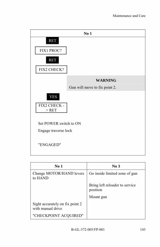
Maintenance and Care
B-GL-372-005/FP-001 143
No 1
RET
FIX1 PROC?
RET
FIX2 CHECK?
WARNING
Gun will move to fix point 2.
YES
FIX2 CHECK -> RET
Set POWER switch to ON
Engage traverse lock
"ENGAGED"
No 1 No 3
Change MOTOR/HAND leversto HAND
Go inside limited zone of gun
Bring left reloader to serviceposition
Mount gun
Sight accurately on fix point 2with manual drive
"CHECKPOINT ACQUIRED"

35 mm Twin Gun GDF 005 Drill Book
B-GL-372-005/FP-001144
No 1 No 3
Look through control optic atcheckpoint
"TRAVERSE DEVIATION ....MIL"
"ELEVATION DEVIATION ....MIL"
If check is OK
"SIGHT ALIGNMENTCHECK FINISHED"
Bring reloader to waitingposition
Go outside limited zone of gun
RET
FIX 2 PROC ?
END
MENU 3
MENU 1 SelectMenu 1.
No 1
If check is not OK, proceed with another checkpoint
If still not correct, inform maintenance personnel
Ensure that nobody is inside the limited zone
Change the MOTOR/HAND levers to MOTOR
Disengage traverse lock
"DISENGAGED"
Set POWER switch to SERVO
"SIGHT ALIGNMENT CHECK FINISHED"
Maintenance and Care
B-GL-372-005/FP-001 145
SECTION 4FAULT-FINDING/TROUBLE SHOOTING
FAULTS ON THE GUN
3. If a fault arises during the operation of the gun and theTROUBLE lamp does not illuminate or flash, the procedure is asfollows:
a. determine the location and nature of the fault byperforming the Functional Check (refer toC-79-214-000/MC-001, Functional Checklist); and
b. correct the fault or report the fault to themaintenance personnel.
ELECTRICAL FAULTS ON THE GUN
4. The lamp TROUBLE on the remote control unit must be offduring normal operation.
5. Malfunctions that are detected by the PSU monitoringcircuits, the Quick Test or the Operational Monitoring are indicated bythe lamp TROUBLE.
6. The following indications are possible:
a. the lamp TROUBLE is illuminated; or
b. the lamp TROUBLE is flashing.
LAMP TROUBLE IS ILLUMINATED
7. The condition indicates a fault in the PSU.
8. In this case the procedure is as follows:

35 mm Twin Gun GDF 005 Drill Book
B-GL-372-005/FP-001146
a. Switch the gun POWER switch to position ON andlock the traverse lock.
b. Set the ERROR/DISPL TEST switch on the PSUcontrol box briefly to ERROR and read the errorcode on the display.
c. Follow the instructions given under the error numberin Section 4.2.4, PSU Error Code List.
LAMP TROUBLE IS FLASHING DURING NORMALOPERATION
No 1
TROUBLE lamp begins flashing
MENU 9 Select Menu 9
RET
Error Code
Look up the first error code displayed by Menu 9 in the list oferror codes in Section 4.2.3.
END
MENU 10
Carry out the procedures described under that error code.
Repeat the operation procedure that was being performed whenthe TROUBLE lamp started flashing.
NOTEIn a combat situation when enemy engagement is imminent,the PSU can be operated despite the presence of errorcodes. In this case, the main switch on the PSU controlpanel is put in the position EMER OPN.

Maintenance and Care
B-GL-372-005/FP-001 147
No 1
If the TROUBLE lamp stops flashing and is switched off, thisindicates that incorrect operation causes the error. Gunoperation can be resumed.
If the TROUBLE lamp continues to flash
MENU 9 Select Menu 9
RET
Error Code
Look up the first error code displayed by Menu 9 in the list oferror codes in Section 4.2.3.
Record the subsystem number given under that error code.
END
MENU 10
Carry out the Functional Check as described in C-79-214-000/MC-001, Functional Checklist.
NOTE
If several error codes are displayed in Menu 9, proceed inaccordance with Section 4.2.2.2 for each of the error codes.
LAMP TROUBLE IS FLASHING AFTER QUICK TEST(MENU 8)
No 1
MENU 9 Select Menu 9
RET
Error Code

35 mm Twin Gun GDF 005 Drill Book
B-GL-372-005/FP-001148
No 1
Look up the first error code displayed by Menu 9 in the list oferror codes in Section 4.2.3.
END
MENU 10
Carry out the procedures described under that error code.
After carrying out the procedures listed under the error code,repeat the Quick Test.
MENU 8 Select Menu 8.
Set NORMAL/TEST switch to TEST.
WARNING
Gun will move erratically.
RET
TEST ACTIVE Quick Test program runs automatically.
MENU 9
Set NORMAL/TEST switch to NORMAL.
If the TROUBLE lamp stops flashing and goes out, thisindicates that the fault has been corrected. Gun operation canbe resumed.
If the TROUBLE lamp continues to flash
MENU 9 Ensure that Menu 9 is selected.
RET
Error Code

Maintenance and Care
B-GL-372-005/FP-001 149
No 1
Look up the first error code displayed by Menu 9 in the list oferror codes in Section 4.2.3.
Record the subsystem number given under that error code.
END
MENU 10
Carry out the Functional Check as described in C-79-214-000/MC-001, Functional Checklist.
NOTES
1. If several error codes are displayed in Menu 9, proceed asdescribed in Section 4.2.2.3 for each of the error codes.
2. If the fault cannot be located and corrected using theFunctional Check, call the maintenance personnel.
GUN ERROR CODES
Gun Error Codes
1501 Gun does not level automatically within 15 seconds
Set POWER switch to OFF.
Engage traverse lock and dismount the gun.
Set PSU NORMAL/LVL ONLY switch to LVL ONLY.
Ensure that the FAST/SLOW control lever is at SLOW.
Level gun using jack controls and the spirit level.
Set PSU NORMAL/LVL ONLY switch to NORMAL.
Mount gun, disengage traverse lock and set POWER switchto SERVO.
Functional Check subsystem number 1500

35 mm Twin Gun GDF 005 Drill Book
B-GL-372-005/FP-001150
Gun Error Codes
3201 Trigger signal is interrupted by the trigger safety circuit
Ensure that:
the fire blocking device is not activated;
the elevation segment is not activated, the end stops ineither the upper or lower positions;
the trigger safety switch is open and that the toggle switchis in the UP position;
the laser/trigger safety plate is showing RED (trigger andlaser fire free) or BLUE, and the laser interrupter switch isconnected and pressed;
both CONVEYOR switches are ON (in the UP position);
both AMMUNITION switches are on REST 3; and
the Fire Sector is correctly entered in Menu 4.
Functional Check subsystem number 3200
3900 No corrective action possible—proceed directly with theFunctional Check
Functional Check subsystem number 3900
3901 RIGHT AUTOMATIC RELOADER FAILED TOCOMPLETE THE RELOADING SEQUENCE
Pull the automatic reloader back to the waiting position.
Ensure that:
the feeler is completely retracted;
the loading arms are in the correct position;
the gun coefficients in Menu 20 are correct;
at least one cartridge clip is in the automatic loader;
there are no skewed cartridge clips in the automaticreloader and automatic loader; and
the unloading lever is in position I.
Carry out the reloading sequence once again.

Maintenance and Care
B-GL-372-005/FP-001 151
Gun Error Codes
If that fails, lock the automatic reloader in the serviceposition with safety lock and switch it OFF at the controlpanel.
If possible, carry out Functional Check.
Functional Check subsystem number 3900
3902 LEFT AUTOMATIC RELOADER FAILED TOCOMPLETE THE RELOADING SEQUENCE
Proceed as per error number 3901 above.
Functional Check subsystem number 3900
3903 NO CARTRIDGE CLIP IN THE RIGHT AUTOMATICLOADER
Place an empty cartridge clip in the right automatic loader.
Functional Check subsystem number 3900
3904 Right safety circuit is not closed
Ensure that:
the automatic reloader is in the waiting position;
the feeler arm is in the correct position; and
the loading arms are in the correct position.
Functional Check subsystem number 3900
3905 No cartridge clip in the left automatic loader
Place an empty cartridge clip in the left automatic loader.
Functional Check subsystem number 3900
3906 Left safety circuit is not closed
Proceed as per error number 3904 above.
Functional Check subsystem number 3900
3907 No signal received from the gun drives
Ensure that:

35 mm Twin Gun GDF 005 Drill Book
B-GL-372-005/FP-001152
Gun Error Codes
the elevation motor is switched ON; and
the gun has been calibrated in traverse and elevation.
Functional Check subsystem number 3900
5100 No corrective action possible—proceed directly with theFunctional Check
Functional Check subsystem number 5100
5101 Gun drives not activated
Switch the traverse and elevation drives ON at the controlpanel.
Ensure that:
Menu 10 shows SECT_LIM MOUNT = 0;
the traverse lock is disengaged;
the MOTOR/HAND levers are on MOTOR; and
the POWER switch is on SERVO.
Functional Check subsystem number 5100
5102 Error in the PSU Mains 2 power supply
Ensure that:
no error indications are on the PSU display;
the Mains 2 power cable (marked blue) is correctlyattached; and
the circuit breakers on the PSU are depressed.
Functional Check subsystem number 5100
5103 Error in the gun trailer Mains 1 power supply
Ensure that:
all circuit breakers on the connector box (F1-F12) aredepressed; and
after pressing the connector box circuit breakers, verifythat the circuit breakers on the PSU are depressed (F1-F3).
Functional Check subsystem number 5100
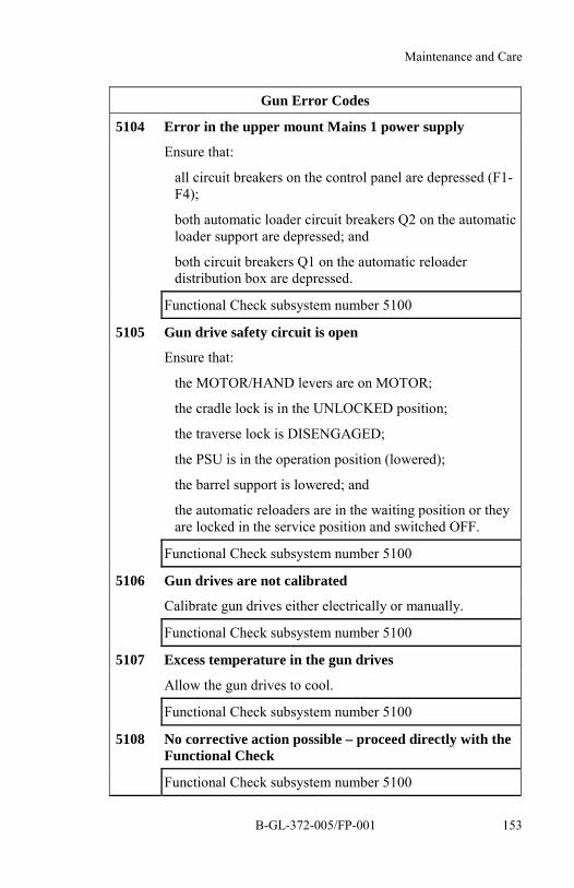
Maintenance and Care
B-GL-372-005/FP-001 153
Gun Error Codes
5104 Error in the upper mount Mains 1 power supply
Ensure that:
all circuit breakers on the control panel are depressed (F1-F4);
both automatic loader circuit breakers Q2 on the automaticloader support are depressed; and
both circuit breakers Q1 on the automatic reloaderdistribution box are depressed.
Functional Check subsystem number 5100
5105 Gun drive safety circuit is open
Ensure that:
the MOTOR/HAND levers are on MOTOR;
the cradle lock is in the UNLOCKED position;
the traverse lock is DISENGAGED;
the PSU is in the operation position (lowered);
the barrel support is lowered; and
the automatic reloaders are in the waiting position or theyare locked in the service position and switched OFF.
Functional Check subsystem number 5100
5106 Gun drives are not calibrated
Calibrate gun drives either electrically or manually.
Functional Check subsystem number 5100
5107 Excess temperature in the gun drives
Allow the gun drives to cool.
Functional Check subsystem number 5100
5108 No corrective action possible – proceed directly with theFunctional Check
Functional Check subsystem number 5100

35 mm Twin Gun GDF 005 Drill Book
B-GL-372-005/FP-001154
Gun Error Codes
5300 No corrective action possible – proceed directly with theFunctional Check
Functional Check subsystem number 5300
5350 No corrective action possible – proceed directly with theFunctional Check
Functional Check subsystem number 5350
5351 Laser excess temperature
During the Quick Test ensure that the NORMAL/TESTswitch is set to TEST.
Allow the laser transmitter to cool.
Functional Check subsystem number 5350
5600 No signals from MV measuring bases
Ensure that:
MV measuring bases are correctly connected; and
cable guide jib is connected to the cradle.
Functional Check subsystem number 5600
5601 No corrective action possible —report the fault to themaintenance personnel
Functional Check subsystem number 5600
5700 No corrective action possible — proceed directly with theFunctional Check
Functional Check subsystem number 5700
5701 Overheating in the electronics cabinet
Check that the fan is working (cooling air can be felt at therear of the cabinet).
Functional Check subsystem number 5700
5900 No corrective action possible — proceed directly with theFunctional Check
Functional Check subsystem number 5900
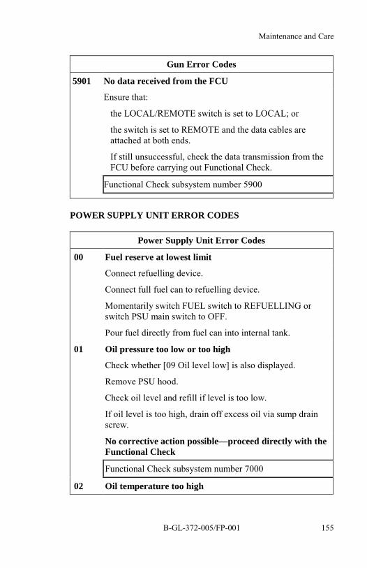
Maintenance and Care
B-GL-372-005/FP-001 155
Gun Error Codes
5901 No data received from the FCU
Ensure that:
the LOCAL/REMOTE switch is set to LOCAL; or
the switch is set to REMOTE and the data cables areattached at both ends.
If still unsuccessful, check the data transmission from theFCU before carrying out Functional Check.
Functional Check subsystem number 5900
POWER SUPPLY UNIT ERROR CODES
Power Supply Unit Error Codes
00 Fuel reserve at lowest limit
Connect refuelling device.
Connect full fuel can to refuelling device.
Momentarily switch FUEL switch to REFUELLING orswitch PSU main switch to OFF.
Pour fuel directly from fuel can into internal tank.
01 Oil pressure too low or too high
Check whether [09 Oil level low] is also displayed.
Remove PSU hood.
Check oil level and refill if level is too low.
If oil level is too high, drain off excess oil via sump drainscrew.
No corrective action possible—proceed directly with theFunctional Check
Functional Check subsystem number 7000
02 Oil temperature too high
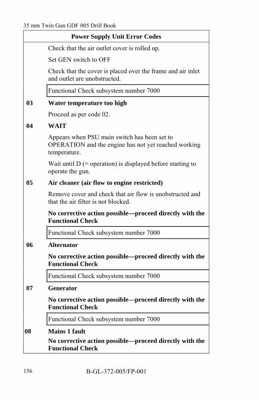
35 mm Twin Gun GDF 005 Drill Book
B-GL-372-005/FP-001156
Power Supply Unit Error Codes
Check that the air outlet cover is rolled up.
Set GEN switch to OFF
Check that the cover is placed over the frame and air inletand outlet are unobstructed.
Functional Check subsystem number 7000
03 Water temperature too high
Proceed as per code 02.
04 WAIT
Appears when PSU main switch has been set toOPERATION and the engine has not yet reached workingtemperature.
Wait until D (= operation) is displayed before starting tooperate the gun.
05 Air cleaner (air flow to engine restricted)
Remove cover and check that air flow is unobstructed andthat the air filter is not blocked.
No corrective action possible—proceed directly with theFunctional Check
Functional Check subsystem number 7000
06 Alternator
No corrective action possible—proceed directly with theFunctional Check
Functional Check subsystem number 7000
07 Generator
No corrective action possible—proceed directly with theFunctional Check
Functional Check subsystem number 7000
08 Mains 1 faultNo corrective action possible—proceed directly with theFunctional Check

Maintenance and Care
B-GL-372-005/FP-001 157
Power Supply Unit Error Codes
Functional Check subsystem number 7000
09 Oil level low
Check that the gun is leveled properly.
Switch off PSU.
Remove cover and check oil level.
Refill if necessary (distance between MIN and MAX markson dipstick corresponds to 1 litre of engine oil).
71 Frequency too high (governor needs adjustment)
No corrective action possible—proceed directly with theFunctional Check
Functional Check subsystem number 7000
72 Frequency too low (governor needs adjustment)
No corrective action possible—proceed directly with theFunctional Check
Functional Check subsystem number 7000
73 Overvoltage (voltage regulator needs adjustment)
No corrective action possible—proceed directly with theFunctional Check
Functional Check subsystem number 7000
74 Undervoltage (voltage regulator needs adjustment)
No corrective action possible – proceed directly with theFunctional Check
Functional Check subsystem number 7000
75 Generator temperature too high

35 mm Twin Gun GDF 005 Drill Book
B-GL-372-005/FP-001158
Power Supply Unit Error Codes
Set PSU main switch to STANDBY. Allow PSU to cool atidling speed.
Check that the air outlet cover is rolled up.
Check that the cover is placed over the frame and air flowinlet and outlet are free of obstruction.
No corrective action possible – proceed directly with theFunctional Check
Functional Check subsystem number 7000
MISFIRES/STOPPAGES ELECTRICAL
No 1
Fire the weapon. If nothing happens, cancel Menu 9 and re-fire theweapon.
If the weapon still does not fire check the following:
TRIGGER switch on remote control unit is ON;
laser/trigger interrupters are activated;
Range Safety Officer (RSO) has Fire Control and Select Systems(FCSS) interrupters on;
weapon is in the fire sector;
ensure weapon is in TRACKING mode; and
AMMUNITION switches are at correct REST position.
If all the above conditions are met and the gun is hot (i.e., the gunhas been fired) No 1 will place the gun in the LOAD position,report the misfire to the RSO, set the POWER switch to OFF, andswitch the CONVEYOR MOTORS to OFF.
The gun position is to be evacuated for a period of 20 minutesbefore any corrective measures are taken.

Maintenance and Care
B-GL-372-005/FP-001 159
No 1 No 2 No 3
Return to the gunand order No 2 and 3
"CHECKPOSITION OFBREECH BLOCK"
Enter safety fence Enter safety fence
Move reloader to SP Move reloader to SP
Open weaponprotective cover
Verify position ofbreech block bychecking theposition of the lugon the return springsleeve assembly
Verify position ofbreech block bychecking theposition of the lugon the return springsleeve assembly
If lug is to the rear,report stoppage toNo 1
If lug is to the rear,report stoppage toNo 1
Report stoppage ormisfire to RangeSafety Officer
If lug is to the front,report misfire to No 1
If lug is to the front,report misfire to No 1
Cock the weapon butdo not release thecocking cable
Cock the weapon butdo not release thecocking handle
Open weapon cover,remove jammed ormisfired round andpass it to No 1
Open weapon cover,remove jammed ormisfired round andpass it to No 1
Inspect the jammedor misfired roundand, if the roundmisfired, place it inthe misfire pit
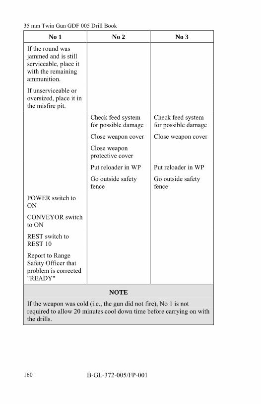
35 mm Twin Gun GDF 005 Drill Book
B-GL-372-005/FP-001160
No 1 No 2 No 3
If the round wasjammed and is stillserviceable, place itwith the remainingammunition.
If unserviceable oroversized, place it inthe misfire pit.
Check feed systemfor possible damage
Check feed systemfor possible damage
Close weapon cover Close weapon cover
Close weaponprotective cover
Put reloader in WP Put reloader in WP
Go outside safetyfence
Go outside safetyfence
POWER switch toON
CONVEYOR switchto ON
REST switch toREST 10
Report to RangeSafety Officer thatproblem is corrected"READY"
NOTE
If the weapon was cold (i.e., the gun did not fire), No 1 is notrequired to allow 20 minutes cool down time before carrying on withthe drills.

Maintenance and Care
B-GL-372-005/FP-001 161
MISFIRES/STOPPAGES MECHANICAL
No 1
Press laser/trigger foot switch.
If nothing happens:
Ensure mechanical firing lever is at F position.
If not, place at F and fire.
If at F position, determine whether the weapon is hot or cold.
The same drills apply as for electrical misfires and stoppages,except:
apply the manual hand brake on the elevation and traversedrive handles after placing the gun in the LOAD position;and
ensure mechanical firing levers are at S.
SECTION 5PREVENTIVE MAINTENANCE
INTRODUCTION
9. All preventive maintenance tasks to be performed by theoperator and the maintainer are listed in the Preventive MaintenanceSchedule (PMS)—-refer to C-79-214-000/NY-001.
10. The PMS lists the tasks in accordance with their periodicityand prescribes by whom the work must be done.
11. To carry out some of the more complex tasks, specialinstructions are necessary. The instructions of the operator tasks arecontained in the Operator Maintenance Instructions (OMI) manual—refer to C-79-214-000/ML-001.
35 mm Twin Gun GDF 005 Drill Book
B-GL-372-005/FP-001162
12. The Detachment Commander is responsible for ensuring thatall preventive maintenance is carried out and that anything outside thedetachment's capability is reported to the FCU Commander.
MATERIALS CHECK
13. The detachment is responsible for the stores on the gun andfor the contents of the cases.
14. The materials check must be carried out periodically, at leastonce a month. For further information use the PMS--refer to C-79-214-000/NY-001.
15. Any damage or loss must be reported to the maintenancepersonnel so that the item can be repaired or replaced.
16. The materials check is to be carried out according to theinventory list WW 804 180, which is contained in the special pocketmounted in the cover of the accessory case.
17. Gun grease, G-403, is identified by contractor part number C2752 550 and/or MIL-G-10924D (9150-21-891-3609). High pressuregrease, Molycote G-N Paste, is identified by contractor part numberW 2753 058 (9150-01-047-9668).
18. The NATO stock numbers for lens paper and cleaningsolution (used to clean Gun King sight and screen) are:
Lens Paper 6640-21-859-5588
Cleaning Solution 6850-21-570-1220
NOTEWhen ordering parts, always state the part name and NATOStock Number.
35 mm Twin Gun GDF 005 Drill Book
B-GL-372-005/FP-001 163
LIST OF ABBREVIATIONS
°C Centigrade
2IC The Detachment Second in Command
AL Automatic Loader
ALIGN Alignment
ALS Automatic Lubrication System
AMM_RELO Ammunition Reload
Ammo Ammunition
AZ Azimuth (bearing)
BAL_NO Ballistic Number
bar Barometric
CALIB Calibrated
CIS Communication and Intercom System
DEG Degrees
DSPL Display
EL Elevation
END End (key)

35 mm Twin Gun GDF 005 Drill Book
B-GL-372-005/FP-001164
F Fire
F_RATE L Firing Rate Left
F_RATE R Firing Rate Right
FCSS Fire Control and Select System
FCU Fire Control Unit
FID Failure Identification
Fired L Fired Left
Fired R Fired Right
FP Firing Point
FPO Firing Point Officer
FSECT Firing Sector
FU Fire Unit
GEN Generator
I/O Input/Output
IFF Identification Friend/Fore
ILLUM Illumination
LIM Limit
LSS Laser Safety Supervisor
LVL Levelling

List of Abbreviations
B-GL-372-005/FP-001 165
M Measure
M/S Metre per second
MAG Magazine
MBAR Millibars
MIL Milliradians
NSN NATO Stock Number
NTDR Near Term Digital Radio
OMI Operator Maintenance Instructions
ORIENT Orientation
PMS Preventive Maintenance Schedule
POS Position
PRESS Pressure
PROC Procedure
psi Pounds per Square Inch
PSU Power Supply Unit
RAN Range
RD Round
RELO Reload
RES Reserve
RET Return (key)

35 mm Twin Gun GDF 005 Drill Book
B-GL-372-005/FP-001166
RSO Range Safety Officer
S Safe
SALVOTIM Salvo Time
sec Second
SECT Sector
SOP Standard Operating Procedure
SP Service Position
T Trigger
TBD To be Determined
TS Training Simulator
TV Television
VES Video Evaluation System
VO Muzzle Velocity Value
VPU Video Presentation Unit
W Warning
WINDIR Wind Direction
WP Waiting Position