ba pnoz s5 en - sensotek.rusensotek.ru/upload/iblock/6a6/6a6761a9863d798508c97c91...pnoz s5...
TRANSCRIPT

PNOZ s5
Operating Manual-21397-EN-09
Safety relays

PrefaceThis document is the original document.
All rights to this documentation are reserved by Pilz GmbH & Co. KG. Copies may be made for internal purposes. Suggestions and comments for improving this documentation will be gratefully received.
Pilz®, PIT®, PMI®, PNOZ®, Primo®, PSEN®, PSS®, PVIS®, SafetyBUS p®, SafetyEYE®, SafetyNET p®, the spirit of safety® are registered and protected trademarks of Pilz GmbH & Co. KG in some countries.
SD means Secure Digital
PNOZ s5
Operating Manual PNOZ s5 21397-EN-09
3
PNOZ s5 safety relayThe safety relay provides a safety-related interruption of a safety circuit.
The safety relay meets the requirements of EN 60947-5-1, EN 60204-1 and VDE 0113-1 and may be used in applications with} E-STOP pushbuttons} Safety gates} Light beam devices
For your safety} Only install and commission the unit if you have read and understood these operating
instructions and are familiar with the applicable regulations for health and safety at work and accident prevention. Ensure VDE and local regulations are met, especially those relating to safety.
} Any guarantee is rendered invalid if the housing is opened or unauthorised modifica-tions are carried out.
} Note for overvoltage category III: If voltages higher than low voltage (>50 V AC or >120 V DC) are present on the unit, connected control elements and sensors must have a rated insulation voltage of at least 250 V
Unit features} Positive-guided relay outputs:
– 2 safety contacts (N/O), instantaneous
– 2 safety contacts (N/O), delay-on de-energisation} 1 semiconductor output} Connection options for:
– E-STOP pushbutton
– Safety gate limit switch
– Start button
– Light beam device
– PSEN} A connector can be used to connect 1 PNOZsigma contact expansion module} Delay-on de-energisation selectable} Operating modes and delay times can be selected via rotary switches} LED indicator for:
– Supply voltage
– Input status, channel 1
– Input status, channel 2
– Switch status channel 1/2
– Start circuit
– Error

PNOZ s5
Operating Manual PNOZ s5 21397-EN-09
4
} Plug-in connection terminals (either spring-loaded terminal or screw terminal)
Safety featuresThe relay meets the following safety requirements:} The circuit is redundant with built-in self-monitoring.} The safety function remains effective in the case of a component failure.} The correct opening and closing of the safety function relays is tested automatically in
each on-off cycle.} The unit has an electronic fuse.
Block diagram/terminal configuration
����������
�� ��
��
��
�� ��
�� ��
��� ���
�
�����
��
��
�� ��
� �
���������
���
��� ���
�
���
���
����
���
���
��
����
����
�
���������������
��
Centre: Front view with cover, right: Front view without cover
Grey highlighted area: Applies only with UB = 48 – 240 V AC/DC
*Insulation between the non-marked area and the relay contacts: Basic insulation (overvolt-age category III), safe separation (overvoltage category II)
Function description} ���� Single-channel operation: no redundancy in the input circuit, earth faults in the start
circuit and input circuit are detected.} Dual-channel operation without detection of shorts across contacts: redundant input cir-
cuit, detects
– earth faults in the start and input circuit,
– short circuits in the input circuit and, with a monitored start, in the start circuit too.

PNOZ s5
Operating Manual PNOZ s5 21397-EN-09
5
} ���� Dual-channel operation with detection of shorts across contacts: redundant input cir-cuit, detects
– earth faults in the start and input circuit,
– short circuits in the input circuit and, with a monitored start, in the start circuit too,
– shorts between contacts in the input circuit.
} Automatic start: Unit is active once the input circuit has been closed.} Manual start: Unit is active once the input circuit is closed and then the start circuit is
closed.
} Monitored start with falling edge: Unit is active once
– the input circuit is closed and then the start circuit is closed and opened again.
– the start circuit is closed and then opened again once the input circuit is closed.
} Monitored start with rising edge: Unit is active once the input circuit is closed and once the start circuit is closed after the waiting period has elapsed (see technical de-tails).
} Start with start-up test: The unit checks whether safety gates that are closed are opened and then closed again when supply voltage is applied.
} Ability to increase the number of contacts available on the
– instantaneous safety contacts by using connectors to link to a PNOZsigma contact expansion module
– delayed/instantaneous safety contacts by connecting contact expansion modules or external contactors
InstallationInstall base unit without contact expansion module: } Ensure that the plug terminator is inserted at the side of the unit.
Connect base unit and PNOZsigma contact expansion module: } Remove the plug terminator at the side of the base unit and at the contact expansion
module.} Connect the base unit and the contact expansion module to the supplied connector be-
fore mounting the units to the DIN rail.
Installation in control cabinet } The safety relay should be installed in a control cabinet with a protection type of at least
IP54.} Use the notch on the rear of the unit to attach it to a DIN rail (35 mm).} When installed vertically: Secure the unit by using a fixing element (e.g. retaining brack-
et or end angle).} Push the device upwards or downwards before lifting it from the DIN rail.

PNOZ s5
Operating Manual PNOZ s5 21397-EN-09
6
WiringPlease note:} Information given in the "Technical details" must be followed.} Outputs 13-14, 23-24 are instantaneous safety contacts, outputs 37-38, 47-48 are de-
lay-on de-energisation safety contacts.} Semiconductor output Y32 should not be used for safety circuits!} To prevent contact welding, a fuse should be connected before the output contacts (see
technical details).} Calculation of the max. cable length lmax in the input circuit:
�����
�������������
Rlmax = max. overall cable resistance (see technical details) Rl / km = cable resistance/km
} Use copper wire that can withstand 60/75 °C.} Sufficient fuse protection must be provided on all output contacts with capacitive and in-
ductive loads.} With UB 48 – 240 VAC/DC: Connect S21 to the protective earth system} When connecting magnetically operated, reed proximity switches, ensure that the max.
peak inrush current (on the input circuit) does not overload the proximity switch.} On 24 VDC devices:
The power supply must comply with the regulations for extra low voltages with safe electrical separation (SELV, PELV) in accordance with VDE 0100, Part 410.
Preparing for operation
Operating modes and delay time
The operating mode and delay time are set via the rotary switches on the unit. You can do this by opening the cover on the front of the unit.
CAUTION!
Do not adjust the rotary switch during operation, otherwise an error mes-sage will appear, the safety contacts will open and the unit will not be ready for operation until the supply voltage has been switched off and then on again.

PNOZ s5
Operating Manual PNOZ s5 21397-EN-09
7
Set operating modes} Switch off supply voltage.} Select operating mode via the operating mode selector switch "mode".} If the operating mode selector switch "mode" is in its start position (vertical position), an
error message will appear.
Operating mode selector switch "mode"
Automatic/man-ual start
Monitored start rising edge
Monitored start falling edge
Automatic start with start-up test
Without detec-tion of shorts across contacts
��������
��������
��������
��������
With detection of shorts across contacts
��������
��������
��������
��������
Set delay time
Time selector switch "t[s]"
Factor selector switch "n"
n x t[s] = Delay time
Example:
t = 4 s, n = 5 Delay time = 5 x 4 = 20 s
Connection} Supply voltage
Supply voltage AC DC
�� �
�� ����
�� ��
�� ��
} Input circuit
Input circuit Single-channel Dual-channel
E-STOPwithout detection of shorts across contacts
�����
���
���
�����
������
E-STOPwith detection of shorts across contacts
��
���
���
���
���
PNOZ s5
Operating Manual PNOZ s5 21397-EN-09
8
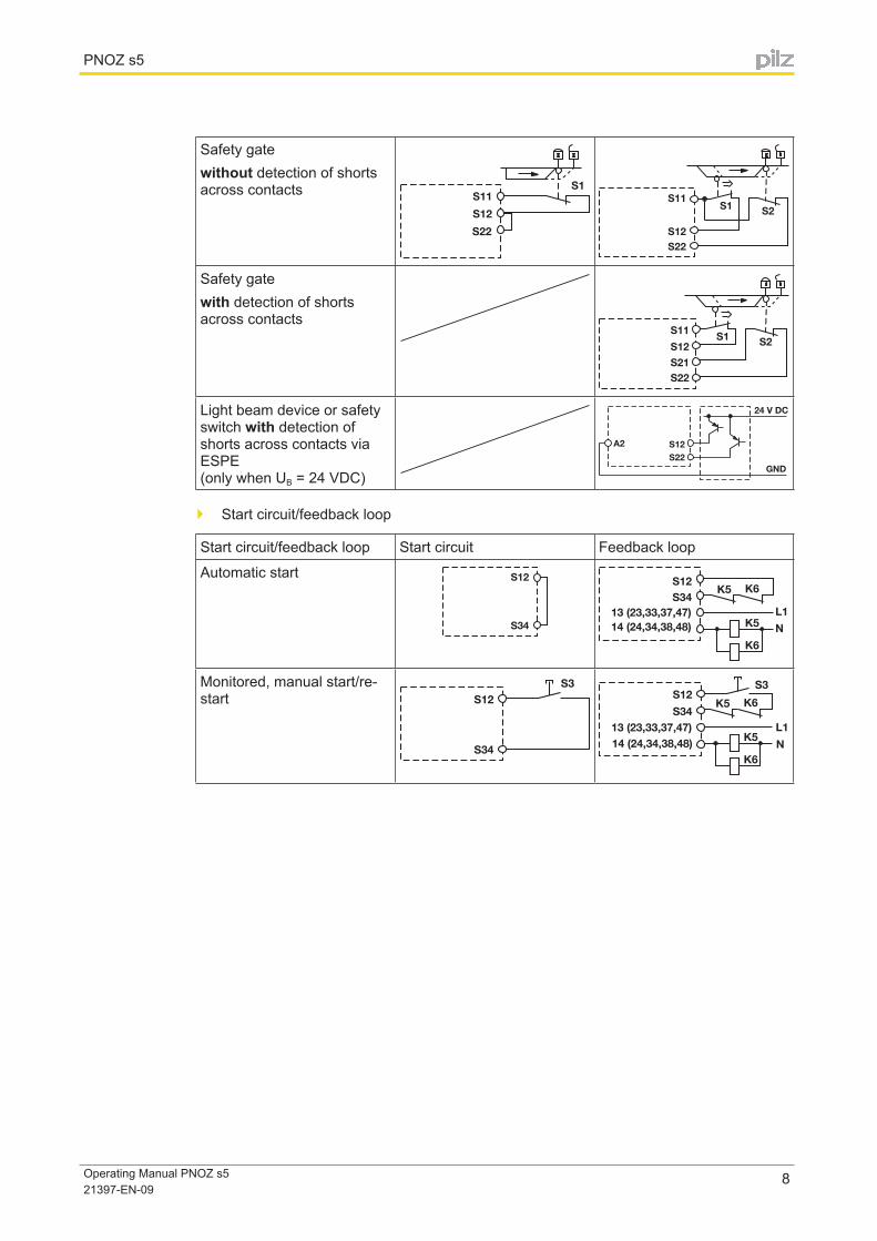
Safety gatewithout detection of shorts across contacts ��
���
���
����� ��
���
������
Safety gatewith detection of shorts across contacts
�� �����
���
������
Light beam device or safety switch with detection of shorts across contacts via ESPE (only when UB = 24 VDC)
������
�������
��
���
} Start circuit/feedback loop
Start circuit/feedback loop Start circuit Feedback loop
Automatic start�� ��
����
�
��
���
�������������������
����������������
Monitored, manual start/re-start ���
���
��
�� ��
����
��
���
���
��
�
��������������������������������
PNOZ s5
Operating Manual PNOZ s5 21397-EN-09
9
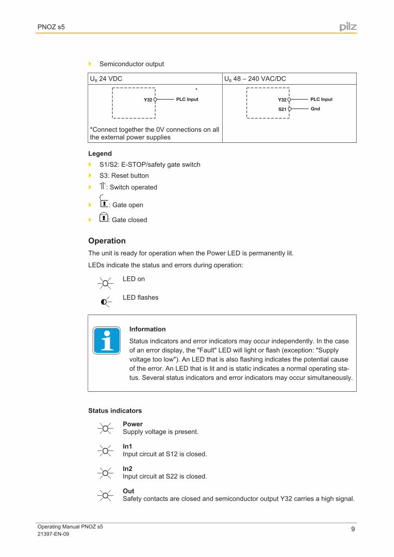
} Semiconductor output
UB 24 VDC UB 48 – 240 VAC/DC
*Connect together the 0V connections on all the external power supplies
Legend} S1/S2: E-STOP/safety gate switch} S3: Reset button
} : Switch operated
} : Gate open
} : Gate closed
OperationThe unit is ready for operation when the Power LED is permanently lit.
LEDs indicate the status and errors during operation:
LED on
LED flashes
Information
Status indicators and error indicators may occur independently. In the case of an error display, the "Fault" LED will light or flash (exception: "Supply voltage too low"). An LED that is also flashing indicates the potential cause of the error. An LED that is lit and is static indicates a normal operating sta-tus. Several status indicators and error indicators may occur simultaneously.
Status indicators
Power Supply voltage is present.
In1 Input circuit at S12 is closed.
In2 Input circuit at S22 is closed.
Out Safety contacts are closed and semiconductor output Y32 carries a high signal.
PNOZ s5
Operating Manual PNOZ s5 21397-EN-09
10
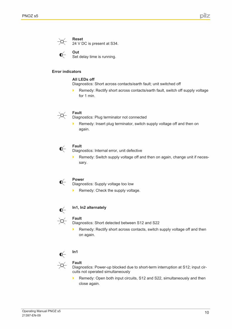
Reset 24 V DC is present at S34.
Out Set delay time is running.
Error indicators
All LEDs off Diagnostics: Short across contacts/earth fault; unit switched off} Remedy: Rectify short across contacts/earth fault, switch off supply voltage
for 1 min.
Fault Diagnostics: Plug terminator not connected} Remedy: Insert plug terminator, switch supply voltage off and then on
again.
Fault Diagnostics: Internal error, unit defective} Remedy: Switch supply voltage off and then on again, change unit if neces-
sary.
Power Diagnostics: Supply voltage too low} Remedy: Check the supply voltage.
In1, In2 alternately
Fault Diagnostics: Short detected between S12 and S22} Remedy: Rectify short across contacts, switch supply voltage off and then
on again.
In1
Fault Diagnostics: Power-up blocked due to short-term interruption at S12; input cir-cuits not operated simultaneously} Remedy: Open both input circuits, S12 and S22, simultaneously and then
close again.
PNOZ s5
Operating Manual PNOZ s5 21397-EN-09
11
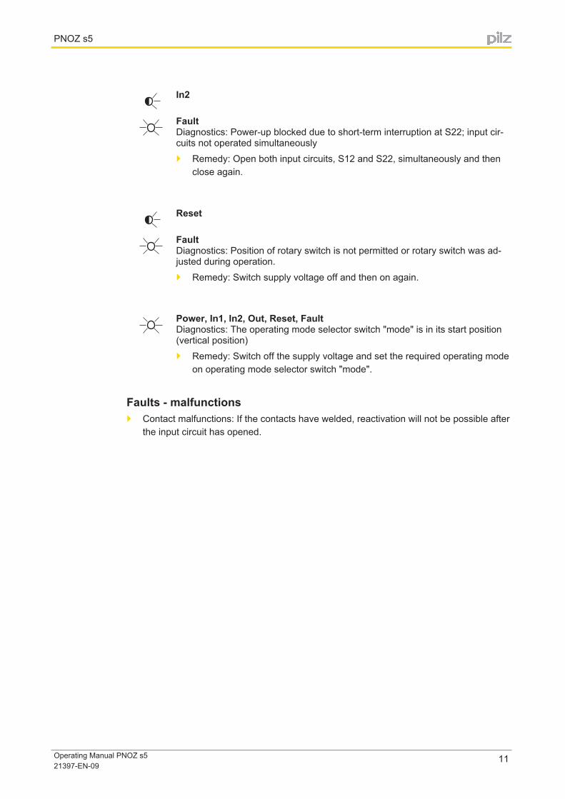
In2
Fault Diagnostics: Power-up blocked due to short-term interruption at S22; input cir-cuits not operated simultaneously} Remedy: Open both input circuits, S12 and S22, simultaneously and then
close again.
Reset
Fault Diagnostics: Position of rotary switch is not permitted or rotary switch was ad-justed during operation.} Remedy: Switch supply voltage off and then on again.
Power, In1, In2, Out, Reset, Fault Diagnostics: The operating mode selector switch "mode" is in its start position (vertical position)} Remedy: Switch off the supply voltage and set the required operating mode
on operating mode selector switch "mode".
Faults - malfunctions} Contact malfunctions: If the contacts have welded, reactivation will not be possible after
the input circuit has opened.

PNOZ s5
Operating Manual PNOZ s5 21397-EN-09
12
Service life graphThe service life graphs indicate the number of cycles from which failures due to wear must be expected. The wear is mainly caused by the electrical load; the mechanical load is negli-gible.
Example} Inductive load: 0,2 A} Utilisation category: AC15} Contact service life: 1,000,000 cycles
Provided the application requires fewer than 1,000,000 cycles, the PFH value (see techni-cal details) can be used in the calculation.
To increase the service life, sufficient spark suppression must be provided on all output contacts. With capacitive loads, any power surges that occur must be noted. With contac-tors, use freewheel diodes for spark suppression.
PNOZ s5
Operating Manual PNOZ s5 21397-EN-09
13
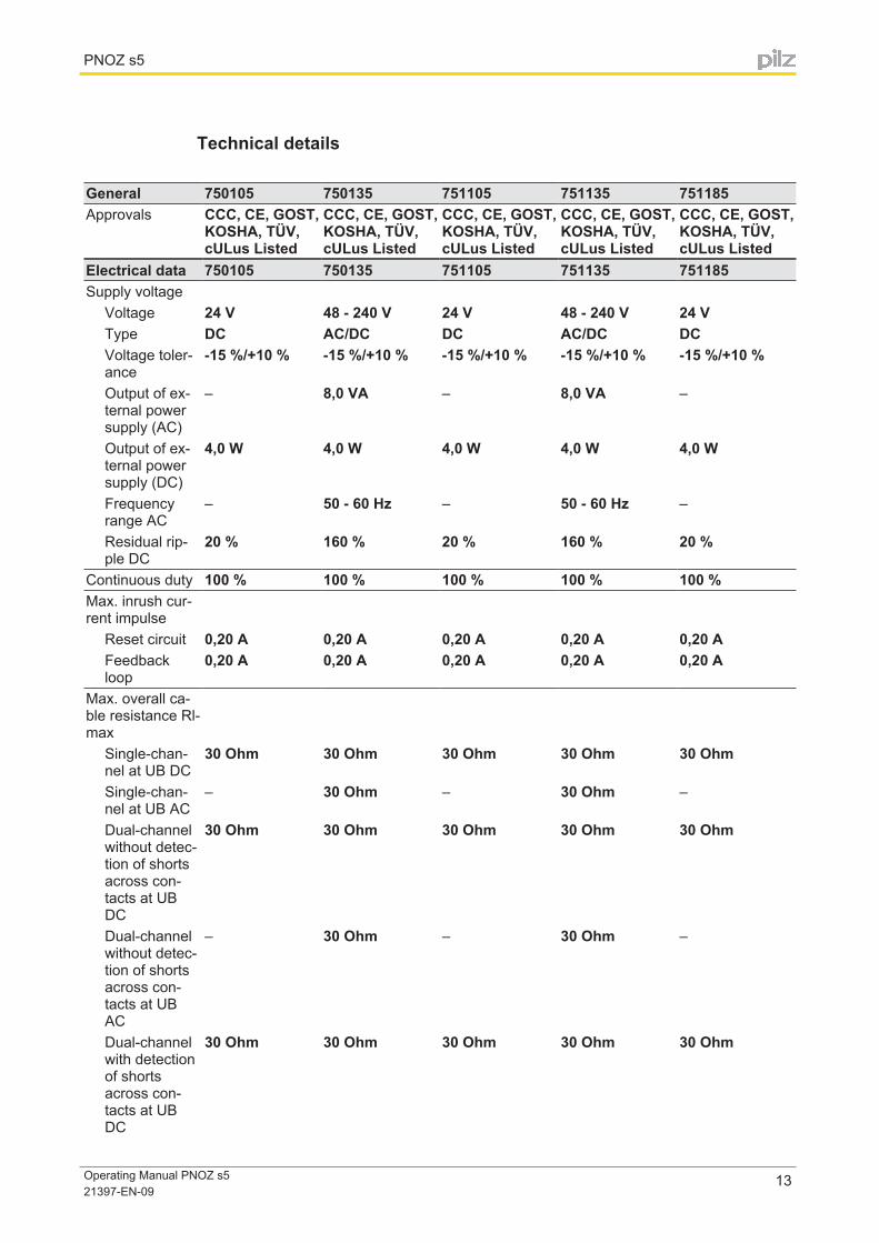
Technical details
General 750105 750135 751105 751135 751185Approvals CCC, CE, GOST,
KOSHA, TÜV, cULus Listed
CCC, CE, GOST, KOSHA, TÜV, cULus Listed
CCC, CE, GOST, KOSHA, TÜV, cULus Listed
CCC, CE, GOST, KOSHA, TÜV, cULus Listed
CCC, CE, GOST, KOSHA, TÜV, cULus Listed
Electrical data 750105 750135 751105 751135 751185Supply voltage
Voltage 24 V 48 - 240 V 24 V 48 - 240 V 24 VType DC AC/DC DC AC/DC DCVoltage toler-ance
-15 %/+10 % -15 %/+10 % -15 %/+10 % -15 %/+10 % -15 %/+10 %
Output of ex-ternal power supply (AC)
– 8,0 VA – 8,0 VA –
Output of ex-ternal power supply (DC)
4,0 W 4,0 W 4,0 W 4,0 W 4,0 W
Frequency range AC
– 50 - 60 Hz – 50 - 60 Hz –
Residual rip-ple DC
20 % 160 % 20 % 160 % 20 %
Continuous duty 100 % 100 % 100 % 100 % 100 %Max. inrush cur-rent impulse
Reset circuit 0,20 A 0,20 A 0,20 A 0,20 A 0,20 AFeedback loop
0,20 A 0,20 A 0,20 A 0,20 A 0,20 A
Max. overall ca-ble resistance Rl-max
Single-chan-nel at UB DC
30 Ohm 30 Ohm 30 Ohm 30 Ohm 30 Ohm
Single-chan-nel at UB AC
– 30 Ohm – 30 Ohm –
Dual-channel without detec-tion of shorts across con-tacts at UB DC
30 Ohm 30 Ohm 30 Ohm 30 Ohm 30 Ohm
Dual-channel without detec-tion of shorts across con-tacts at UB AC
– 30 Ohm – 30 Ohm –
Dual-channel with detection of shorts across con-tacts at UB DC
30 Ohm 30 Ohm 30 Ohm 30 Ohm 30 Ohm
PNOZ s5
Operating Manual PNOZ s5 21397-EN-09
14
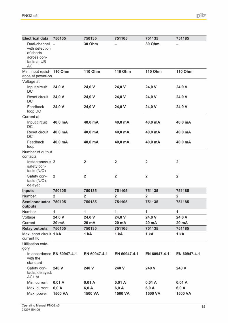
Electrical data 750105 750135 751105 751135 751185Dual-channel with detection of shorts across con-tacts at UB AC
– 30 Ohm – 30 Ohm –
Min. input resist-ance at power-on
110 Ohm 110 Ohm 110 Ohm 110 Ohm 110 Ohm
Voltage atInput circuit DC
24,0 V 24,0 V 24,0 V 24,0 V 24,0 V
Reset circuit DC
24,0 V 24,0 V 24,0 V 24,0 V 24,0 V
Feedback loop DC
24,0 V 24,0 V 24,0 V 24,0 V 24,0 V
Current atInput circuit DC
40,0 mA 40,0 mA 40,0 mA 40,0 mA 40,0 mA
Reset circuit DC
40,0 mA 40,0 mA 40,0 mA 40,0 mA 40,0 mA
Feedback loop
40,0 mA 40,0 mA 40,0 mA 40,0 mA 40,0 mA
Number of output contacts
Instantaneous safety con-tacts (N/O)
2 2 2 2 2
Safety con-tacts (N/O), delayed
2 2 2 2 2
Inputs 750105 750135 751105 751135 751185Number 2 2 2 2 2Semiconductor outputs
750105 750135 751105 751135 751185
Number 1 1 1 1 1Voltage 24,0 V 24,0 V 24,0 V 24,0 V 24,0 VCurrent 20 mA 20 mA 20 mA 20 mA 20 mARelay outputs 750105 750135 751105 751135 751185Max. short circuit current IK
1 kA 1 kA 1 kA 1 kA 1 kA
Utilisation cate-gory
In accordance with the standard
EN 60947-4-1 EN 60947-4-1 EN 60947-4-1 EN 60947-4-1 EN 60947-4-1
Safety con-tacts, delayed: AC1 at
240 V 240 V 240 V 240 V 240 V
Min. current 0,01 A 0,01 A 0,01 A 0,01 A 0,01 AMax. current 6,0 A 6,0 A 6,0 A 6,0 A 6,0 AMax. power 1500 VA 1500 VA 1500 VA 1500 VA 1500 VA
PNOZ s5
Operating Manual PNOZ s5 21397-EN-09
15
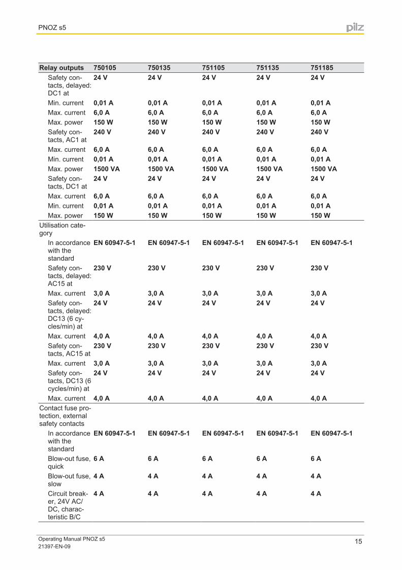
Relay outputs 750105 750135 751105 751135 751185Safety con-tacts, delayed: DC1 at
24 V 24 V 24 V 24 V 24 V
Min. current 0,01 A 0,01 A 0,01 A 0,01 A 0,01 AMax. current 6,0 A 6,0 A 6,0 A 6,0 A 6,0 AMax. power 150 W 150 W 150 W 150 W 150 WSafety con-tacts, AC1 at
240 V 240 V 240 V 240 V 240 V
Max. current 6,0 A 6,0 A 6,0 A 6,0 A 6,0 AMin. current 0,01 A 0,01 A 0,01 A 0,01 A 0,01 AMax. power 1500 VA 1500 VA 1500 VA 1500 VA 1500 VASafety con-tacts, DC1 at
24 V 24 V 24 V 24 V 24 V
Max. current 6,0 A 6,0 A 6,0 A 6,0 A 6,0 AMin. current 0,01 A 0,01 A 0,01 A 0,01 A 0,01 AMax. power 150 W 150 W 150 W 150 W 150 W
Utilisation cate-gory
In accordance with the standard
EN 60947-5-1 EN 60947-5-1 EN 60947-5-1 EN 60947-5-1 EN 60947-5-1
Safety con-tacts, delayed: AC15 at
230 V 230 V 230 V 230 V 230 V
Max. current 3,0 A 3,0 A 3,0 A 3,0 A 3,0 ASafety con-tacts, delayed: DC13 (6 cy-cles/min) at
24 V 24 V 24 V 24 V 24 V
Max. current 4,0 A 4,0 A 4,0 A 4,0 A 4,0 ASafety con-tacts, AC15 at
230 V 230 V 230 V 230 V 230 V
Max. current 3,0 A 3,0 A 3,0 A 3,0 A 3,0 ASafety con-tacts, DC13 (6 cycles/min) at
24 V 24 V 24 V 24 V 24 V
Max. current 4,0 A 4,0 A 4,0 A 4,0 A 4,0 AContact fuse pro-tection, external safety contacts
In accordance with the standard
EN 60947-5-1 EN 60947-5-1 EN 60947-5-1 EN 60947-5-1 EN 60947-5-1
Blow-out fuse, quick
6 A 6 A 6 A 6 A 6 A
Blow-out fuse, slow
4 A 4 A 4 A 4 A 4 A
Circuit break-er, 24V AC/DC, charac-teristic B/C
4 A 4 A 4 A 4 A 4 A
PNOZ s5
Operating Manual PNOZ s5 21397-EN-09
16
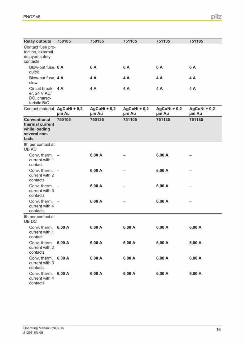
Relay outputs 750105 750135 751105 751135 751185Contact fuse pro-tection, external delayed safety contacts
Blow-out fuse, quick
6 A 6 A 6 A 6 A 6 A
Blow-out fuse, slow
4 A 4 A 4 A 4 A 4 A
Circuit break-er, 24 V AC/DC, charac-teristic B/C
4 A 4 A 4 A 4 A 4 A
Contact material AgCuNi + 0,2 µm Au
AgCuNi + 0,2 µm Au
AgCuNi + 0,2 µm Au
AgCuNi + 0,2 µm Au
AgCuNi + 0,2 µm Au
Conventional thermal current while loading several con-tacts
750105 750135 751105 751135 751185
Ith per contact at UB AC
Conv. therm. current with 1 contact
– 6,00 A – 6,00 A –
Conv. therm. current with 2 contacts
– 6,00 A – 6,00 A –
Conv. therm. current with 3 contacts
– 6,00 A – 6,00 A –
Conv. therm. current with 4 contacts
– 6,00 A – 6,00 A –
Ith per contact at UB DC
Conv. therm. current with 1 contact
6,00 A 6,00 A 6,00 A 6,00 A 6,00 A
Conv. therm. current with 2 contacts
6,00 A 6,00 A 6,00 A 6,00 A 6,00 A
Conv. therm. current with 3 contacts
6,00 A 6,00 A 6,00 A 6,00 A 6,00 A
Conv. therm. current with 4 contacts
6,00 A 6,00 A 6,00 A 6,00 A 6,00 A
PNOZ s5
Operating Manual PNOZ s5 21397-EN-09
17
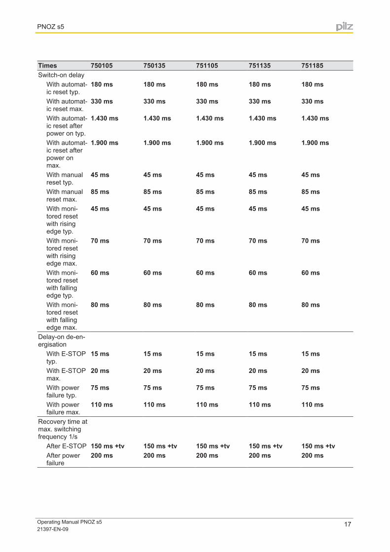
Times 750105 750135 751105 751135 751185Switch-on delay
With automat-ic reset typ.
180 ms 180 ms 180 ms 180 ms 180 ms
With automat-ic reset max.
330 ms 330 ms 330 ms 330 ms 330 ms
With automat-ic reset after power on typ.
1.430 ms 1.430 ms 1.430 ms 1.430 ms 1.430 ms
With automat-ic reset after power on max.
1.900 ms 1.900 ms 1.900 ms 1.900 ms 1.900 ms
With manual reset typ.
45 ms 45 ms 45 ms 45 ms 45 ms
With manual reset max.
85 ms 85 ms 85 ms 85 ms 85 ms
With moni-tored reset with rising edge typ.
45 ms 45 ms 45 ms 45 ms 45 ms
With moni-tored reset with rising edge max.
70 ms 70 ms 70 ms 70 ms 70 ms
With moni-tored reset with falling edge typ.
60 ms 60 ms 60 ms 60 ms 60 ms
With moni-tored reset with falling edge max.
80 ms 80 ms 80 ms 80 ms 80 ms
Delay-on de-en-ergisation
With E-STOP typ.
15 ms 15 ms 15 ms 15 ms 15 ms
With E-STOP max.
20 ms 20 ms 20 ms 20 ms 20 ms
With power failure typ.
75 ms 75 ms 75 ms 75 ms 75 ms
With power failure max.
110 ms 110 ms 110 ms 110 ms 110 ms
Recovery time at max. switching frequency 1/s
After E-STOP 150 ms +tv 150 ms +tv 150 ms +tv 150 ms +tv 150 ms +tvAfter power failure
200 ms 200 ms 200 ms 200 ms 200 ms
PNOZ s5
Operating Manual PNOZ s5 21397-EN-09
18
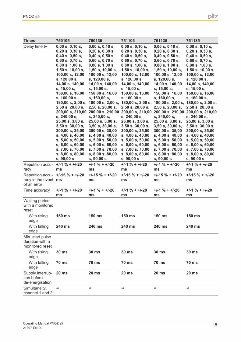
Times 750105 750135 751105 751135 751185Delay time tv 0,00 s, 0,10 s,
0,20 s, 0,30 s, 0,40 s, 0,50 s, 0,60 s, 0,70 s, 0,80 s, 1,00 s, 1,50 s, 10,00 s, 100,00 s, 12,00 s, 120,00 s, 14,00 s, 140,00 s, 15,00 s, 150,00 s, 16,00 s, 160,00 s, 180,00 s, 2,00 s, 2,50 s, 20,00 s, 200,00 s, 210,00 s, 240,00 s, 25,00 s, 3,00 s, 3,50 s, 30,00 s, 300,00 s, 35,00 s, 4,00 s, 40,00 s, 5,00 s, 50,00 s, 6,00 s, 60,00 s, 7,00 s, 70,00 s, 8,00 s, 80,00 s, 90,00 s
0,00 s, 0,10 s, 0,20 s, 0,30 s, 0,40 s, 0,50 s, 0,60 s, 0,70 s, 0,80 s, 1,00 s, 1,50 s, 10,00 s, 100,00 s, 12,00 s, 120,00 s, 14,00 s, 140,00 s, 15,00 s, 150,00 s, 16,00 s, 160,00 s, 180,00 s, 2,00 s, 2,50 s, 20,00 s, 200,00 s, 210,00 s, 240,00 s, 25,00 s, 3,00 s, 3,50 s, 30,00 s, 300,00 s, 35,00 s, 4,00 s, 40,00 s, 5,00 s, 50,00 s, 6,00 s, 60,00 s, 7,00 s, 70,00 s, 8,00 s, 80,00 s, 90,00 s
0,00 s, 0,10 s, 0,20 s, 0,30 s, 0,40 s, 0,50 s, 0,60 s, 0,70 s, 0,80 s, 1,00 s, 1,50 s, 10,00 s, 100,00 s, 12,00 s, 120,00 s, 14,00 s, 140,00 s, 15,00 s, 150,00 s, 16,00 s, 160,00 s, 180,00 s, 2,00 s, 2,50 s, 20,00 s, 200,00 s, 210,00 s, 240,00 s, 25,00 s, 3,00 s, 3,50 s, 30,00 s, 300,00 s, 35,00 s, 4,00 s, 40,00 s, 5,00 s, 50,00 s, 6,00 s, 60,00 s, 7,00 s, 70,00 s, 8,00 s, 80,00 s, 90,00 s
0,00 s, 0,10 s, 0,20 s, 0,30 s, 0,40 s, 0,50 s, 0,60 s, 0,70 s, 0,80 s, 1,00 s, 1,50 s, 10,00 s, 100,00 s, 12,00 s, 120,00 s, 14,00 s, 140,00 s, 15,00 s, 150,00 s, 16,00 s, 160,00 s, 180,00 s, 2,00 s, 2,50 s, 20,00 s, 200,00 s, 210,00 s, 240,00 s, 25,00 s, 3,00 s, 3,50 s, 30,00 s, 300,00 s, 35,00 s, 4,00 s, 40,00 s, 5,00 s, 50,00 s, 6,00 s, 60,00 s, 7,00 s, 70,00 s, 8,00 s, 80,00 s, 90,00 s
0,00 s, 0,10 s, 0,20 s, 0,30 s, 0,40 s, 0,50 s, 0,60 s, 0,70 s, 0,80 s, 1,00 s, 1,50 s, 10,00 s, 100,00 s, 12,00 s, 120,00 s, 14,00 s, 140,00 s, 15,00 s, 150,00 s, 16,00 s, 160,00 s, 180,00 s, 2,00 s, 2,50 s, 20,00 s, 200,00 s, 210,00 s, 240,00 s, 25,00 s, 3,00 s, 3,50 s, 30,00 s, 300,00 s, 35,00 s, 4,00 s, 40,00 s, 5,00 s, 50,00 s, 6,00 s, 60,00 s, 7,00 s, 70,00 s, 8,00 s, 80,00 s, 90,00 s
Repetition accu-racy
+/-1 % + +/-20 ms
+/-1 % + +/-20 ms
+/-1 % + +/-20 ms
+/-1 % + +/-20 ms
+/-1 % + +/-20 ms
Repetition accu-racy in the event of an error
+/-15 % + +/-20 ms
+/-15 % + +/-20 ms
+/-15 % + +/-20 ms
+/-15 % + +/-20 ms
+/-15 % + +/-20 ms
Time accuracy +/-1 % + +/-20 ms
+/-1 % + +/-20 ms
+/-1 % + +/-20 ms
+/-1 % + +/-20 ms
+/-1 % + +/-20 ms
Waiting period with a monitored reset
With rising edge
150 ms 150 ms 150 ms 150 ms 150 ms
With falling edge
240 ms 240 ms 240 ms 240 ms 240 ms
Min. start pulse duration with a monitored reset
With rising edge
30 ms 30 ms 30 ms 30 ms 30 ms
With falling edge
70 ms 70 ms 70 ms 70 ms 70 ms
Supply interrup-tion before de-energisation
20 ms 20 ms 20 ms 20 ms 20 ms
Simultaneity, channel 1 and 2
∞ ∞ ∞ ∞ ∞

PNOZ s5
Operating Manual PNOZ s5 21397-EN-09
19
Environmental data
750105 750135 751105 751135 751185
Climatic suitabili-ty
EN 60068-2-78 EN 60068-2-78 EN 60068-2-78 EN 60068-2-78 EN 60068-2-78
Ambient temper-ature
Temperature range
-10 - 55 °C -10 - 55 °C -10 - 55 °C -10 - 55 °C -10 - 55 °C
Storage temper-ature
Temperature range
-40 - 85 °C -40 - 85 °C -40 - 85 °C -40 - 85 °C -40 - 85 °C
EMC EN 60947-5-1, EN 61000-6-2, EN 61000-6-4
EN 60947-5-1, EN 61000-6-2, EN 61000-6-4
EN 60947-5-1, EN 61000-6-2, EN 61000-6-4
EN 60947-5-1, EN 61000-6-2, EN 61000-6-4
EN 60947-5-1, EN 61000-6-2, EN 61000-6-4
VibrationIn accordance with the standard
EN 60068-2-6 EN 60068-2-6 EN 60068-2-6 EN 60068-2-6 EN 60068-2-6
Frequency 10,0 - 55,0 Hz 10,0 - 55,0 Hz 10,0 - 55,0 Hz 10,0 - 55,0 Hz 10,0 - 55,0 HzMax. ampli-tude
0,35 mm 0,35 mm 0,35 mm 0,35 mm 0,35 mm
Airgap creepageIn accordance with the standard
EN 60947-1 EN 60947-1 EN 60947-1 EN 60947-1 EN 60947-1
Overvoltage category
III / II III / II III / II III / II III / II
Pollution de-gree
2 2 2 2 2
Rated insulation voltage
250 V 250 V 250 V 250 V 250 V
Rated impulse withstand voltage
4,00 kV 4,00 kV 4,00 kV 4,00 kV 4,00 kV
Protection typeMounting (e.g. cabinet)
IP54 IP54 IP54 IP54 IP54
Housing IP40 IP40 IP40 IP40 IP40Terminals IP20 IP20 IP20 IP20 IP20
Mechanical data 750105 750135 751105 751135 751185Mounting posi-tion
Any Any Any Any Any
Mechanical life 10,000,000 cy-cles
10,000,000 cy-cles
10,000,000 cy-cles
10,000,000 cy-cles
10,000,000 cy-cles
MaterialBottom PC PC PC PC PCFront PC PC PC PC PCTop PC PC PC PC PC
PNOZ s5
Operating Manual PNOZ s5 21397-EN-09
20
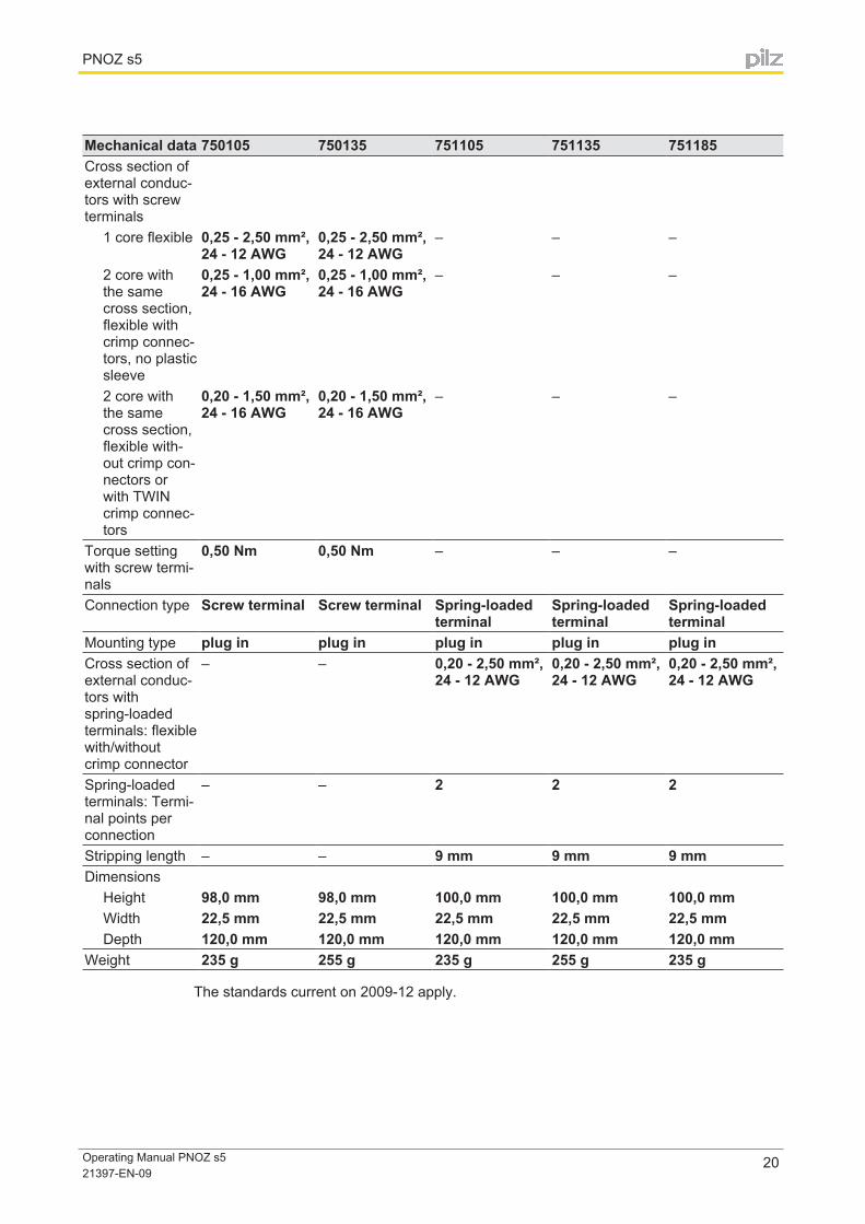
Mechanical data 750105 750135 751105 751135 751185Cross section of external conduc-tors with screw terminals
1 core flexible 0,25 - 2,50 mm², 24 - 12 AWG
0,25 - 2,50 mm², 24 - 12 AWG
– – –
2 core with the same cross section, flexible with crimp connec-tors, no plastic sleeve
0,25 - 1,00 mm², 24 - 16 AWG
0,25 - 1,00 mm², 24 - 16 AWG
– – –
2 core with the same cross section, flexible with-out crimp con-nectors or with TWIN crimp connec-tors
0,20 - 1,50 mm², 24 - 16 AWG
0,20 - 1,50 mm², 24 - 16 AWG
– – –
Torque setting with screw termi-nals
0,50 Nm 0,50 Nm – – –
Connection type Screw terminal Screw terminal Spring-loaded terminal
Spring-loaded terminal
Spring-loaded terminal
Mounting type plug in plug in plug in plug in plug inCross section of external conduc-tors with spring-loaded terminals: flexible with/without crimp connector
– – 0,20 - 2,50 mm², 24 - 12 AWG
0,20 - 2,50 mm², 24 - 12 AWG
0,20 - 2,50 mm², 24 - 12 AWG
Spring-loaded terminals: Termi-nal points per connection
– – 2 2 2
Stripping length – – 9 mm 9 mm 9 mmDimensions
Height 98,0 mm 98,0 mm 100,0 mm 100,0 mm 100,0 mmWidth 22,5 mm 22,5 mm 22,5 mm 22,5 mm 22,5 mmDepth 120,0 mm 120,0 mm 120,0 mm 120,0 mm 120,0 mm
Weight 235 g 255 g 235 g 255 g 235 g
The standards current on 2009-12 apply.

PNOZ s5
Operating Manual PNOZ s5 21397-EN-09
21
Safety characteristic data
Operating mode
EN ISO 13849-1: 2006PL
EN ISO 13849-1: 2006Category
EN IEC 62061SIL CL
EN IEC 62061PFHD [1/h]
IEC 61511SIL
IEC 61511PFD
EN ISO 13849-1: 2006TM [year]
Safety con-tacts, instan-taneous
PL e Cat. 4 SIL CL 3 2,31E-09 SIL 3 2,03E-06 20
Safety con-tacts, de-layed
PL e Cat. 4 SIL CL 3 2,34E-09 SIL 3 2,75E-05 20
All the units used within a safety function must be considered when calculating the safety characteristic data.
Information
A safety function's SIL/PL values are not identical to the SIL/PL values of the units that are used and may be different. We recommend that you use the PAScal software tool to calculate the safety function's SIL/PL values.
ATTENTION!
It is essential to consider the relay's service life graphs. The relay outputs' safety-related characteristic data is only valid if the values in the service life graphs are met.
The PFH value depends on the switching frequency and the load on the relay output. If the service life graphs are not accessible, the stated PFH value can be used irrespective of the switching frequency and the load, as the PFH value already considers the relay's B10d val-ue as well as the failure rates of the other components.
Order reference
Order reference
Product type Features TerminalsOrder no.
PNOZ s5 24 VDC Screw terminals 750 105
PNOZ s5 C 24 VDC Spring-loaded terminals 751 105
PNOZ s5 C (coated ver-sion)
24 VDC Spring-loaded terminals 751 185
PNOZ s5 48 - 240 VAC/DC Screw terminals 750 135
PNOZ s5 C 48 - 240 VAC/DC Spring-loaded terminals 751 135
PNOZ s5
Operating Manual PNOZ s5 21397-EN-09
22
EC declaration of conformityThis product/these products meet the requirements of the directive 2006/42/EC for machin-ery of the European Parliament and of the Council. The complete EC Declaration of Con-formity is available on the Internet at www.pilz.com/downloads. Representative: Norbert Fröhlich, Pilz GmbH & Co. KG, Felix-Wankel-Str. 2, 73760 Ostfil-dern, Germany
...
Sac
hnum
mer
Prin
ted
in G
erm
any
©
Pilz
Gm
bH &
Co.
KG
, 201
1
+49 711 [email protected]
Pilz GmbH & Co. KGFelix-Wankel-Straße 273760 Ostfildern, GermanyTelephone: +49 711 3409-0Telefax: +49 711 3409-133E-Mail: [email protected]: www.pilz.com
Technical supportIn many countries we are represented by our subsidiaries and sales partners.
Please refer to our homepage for further details or contact our headquarters.
Indu
raN
ET
p®, P
ilz®, P
IT®, P
MC
prot
ego®
, PM
I®, P
NO
Z®, P
rimo®
, PS
EN
®, P
SS
®, P
VIS
®, S
afet
yBU
S p
®, S
afet
yEY
E®, S
afet
yNE
T p®
, the
spi
rit o
f saf
ety®
are
reg
iste
red
and
prot
ecte
d tr
adem
arks
of
Pilz
Gm
bH &
Co.
KG
in s
ome
coun
trie
s. W
e w
ould
poi
nt o
ut th
at p
rodu
ct fe
atur
es m
ay v
ary
from
the
deta
ils s
tate
d in
this
doc
umen
t, de
pend
ing
on th
e st
atus
at t
he ti
me
of p
ublic
atio
n an
d th
e sc
ope
of th
e eq
uipm
ent.
We
acce
pt n
o re
spon
sibi
lity
for
the
valid
ity, a
ccur
acy
and
entir
ety
of th
e te
xt a
nd g
raph
ics
pres
ente
d in
this
info
rmat
ion.
Ple
ase
cont
act o
ur T
echn
ical
Sup
port
if y
ou h
ave
any
ques
tions
.
2139
7-E
N-0
9, 2
013-
05 P
rinte
d in
Ger
man
y ©
Pilz
Gm
bH &
Co.
KG
, 201
1
Back cover