background report reference ap-42 section …...the file name "ref02_c01s02.pdf" would...
TRANSCRIPT

Background Report Reference
AP-42 Section Number: 9.6.1
Background Chapter: 4
Reference Number: 2
Title: Results of the December 28, 1988 Particulate Emission Compliance Test on the Rogers Dryer at the Land O'Lakes Plant Located in Spencer, Wisconsin
Interpol1 Laboratories, Inc.
December 1988

I n t e r p o l l Laborator ies, Inc. 4500 B a l l Road N.E.
C i r c l e Pines, Uinnesota 55014-1819
TEL: (612) 786-6020 FAX: (612) 786-7854
RESULTS OF THE DECEUBER 28, I988
ON THE ROGERS DRYER AT THE LAND 0’ LAKES PARTICULATE EUISSION CWPLIANCE TEST
LAND 0’ LAKES P.O. Box 116
Minneapolis, Uinnesota 55440
At ten t ion : Dele H a r r i s
Report Number 8-2695 December 30, 1988 KE/klq
Approved by:
Kathleen E i cksdadt Senior Data Analyst F i e l d Testing D i v i s i o n
,
, . . . ...
,

TABLE OF CONTENTS
i
ABBREVIATIONS
1 INTROOUCTION
2 S W R Y AND DISCUSSION
3 RESULTS
3 .1
3.2
Results o f Orsat and Moisture Analyses
Results o f P a r t i c u l a t e Loading Determinations
APPENDICES :
lii
1
3 . . .. . ... . .
A - Results o f Pre l iminary Volumetric Flow Rate Determinations
B - Location o f Test Por ts
C - Methods 2 - 5 F i e l d Data Sheets
D - Laboratory Data Sheets
E - Process Data
F - Procedures
G - Calcu lat ion Equations
H - Sampling T r a i n C a l i b r a t i o n Data
.. . . .... .... ....
. . . . . , ...
... > . ... . :".: :.. .': . .. . . .. .. . . ....... ...... .....
L ~~
t ACFH cc ( m l ) DSCFH DSHL DEG-F (OF)
D I A . FP Fr /SEC 9 GPH GR/ACF GR/DSCF g/dscm HP HRS I N . 1N.HG. 1N.WC. ~
LB LB/DSCF LB/HR LB/lOoBTU LB/HHBTU LTPD HW mg/DSCH microns (um) WIN. ng ohm-cm PH PPH PPH PpmC ppm, d P P m T W P P t P S I SQ.FT. ug v/v w/w <
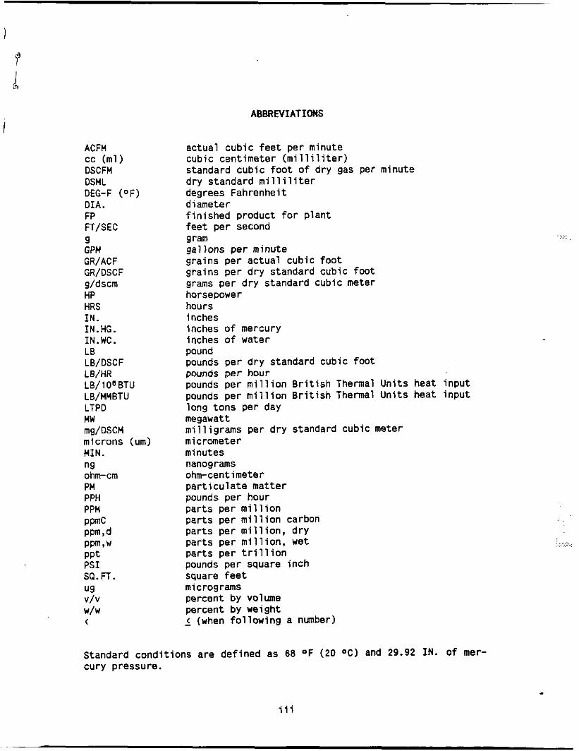
ABBREVIATIONS
actual cubic f e e t per minute cubic cent imeter ( m i l l i l i t e r ) standard cubic f o o t o f dry gas per minute dry standard m i l l i l i t e r degrees Fahrenheit diameter f i n i shed product f o r p lant f e e t per second
gal lons per minute grains per actua l cubic f o o t grains per d ry standard cubic f o o t grams per d ry standard cubic meter horsepower hours inches inches o f mercury inches o f water pound pounds per d ry standard cubic f o o t pounds per hour pounds per m i l l i o n B r i t i s h Thermal Un i t s heat i npu t pounds per m i l l i o n B r i t i s h Thermal U n i t s heat i npu t long tons per day megawatt m i l l i g rams per d ry standard cubic meter micrometer minutes nanograms ohm-cent imeter p a r t i c u l a t e matter pounds per hour par ts per m i l l i o n par ts per m i l l i o n carbon par ts per m i l l i o n , d ry par ts per m i l l i o n , wet par ts per tr i 11 ion pounds per square i nch square f e e t micrograms percent by volume percent by weight - < (when f o l l o w i n g a number)
gram .... .....
. . . .., ...: .... .
Standard condi t ions are defined as 68 OF (20 O C ) and 29.92 IN. o f mer- cury pressure.
iii

1 INTRODUCTION
On December 28, 1988 I n t e r p o l l Laborator ies personnel conducted a
p a r t i c u l a t e emission compliance t e s t on t h e Rogers Dryer a t t he Land 0 '
Lakes P lan t located i n Spencer, Wisconsin. On-site t e s t i n g was performed
by E. Trowbridge and C. Hosser. Coordination between t e s t i n g a c t i v i t i e s
and p l a n t operation was provided by Dale H a r r i s o f Land 0' Lakes Inc. The
t e s t was witnessed by Neal Baudhuin o f t h e Wisconsin Department o f Natura l
Resources.
.. . . ..
The dryer tes ted i s a C. E. Rogers custom designed spray dryer . I t
i s d i r e c t f i r e d with na tu ra l gas and has a ra ted caDacitv o f 1980 LB/HR
o f d ry product. P a r t i c u l a t e emissions from t h e dryer are c o n t r o l l e d by
a C. E . Rogers wet ven tu r i scrubber. ,
Evaluations were performed i n accordance w i t h EPA Methods 1 - 5,
CFR T i t l e 40, Part 60, Appendix A ( rev ised J u l y 1, 1987). A pre l im ina ry
determinat ion o f t he gas l i n e a r v e l o c i t y p r o f i l e was made before the f i r s t
p a r t i c u l a t e determination t o a l low se lec t i on o f t he appropr ia te nozz le
diameter requi red f o r i s o k i n e t i c sample withdrawal. An I n t e r p o l l Labs
sampling t r a i n which meets o r exceeds spec i f i ca t i ons i n the above-cited
reference was used t o e x t r a c t p a r t i c u l a t e samples by means o f a heated
g lass- l ined probe. Wet catch samples were co l l ec ted i n the back h a l f o f
the Method 5 sampling t r a i n and analyzed as per Wisconsin DNR pro toco l . .. .
.~ . . ... An in tegrated f l u e gas sample was ex t rac ted simultaneously w i t h each . .
p a r t i c u l a t e sample us ing a spec ia l l y designed gas sampling system. ~ . i
. . - _ . .
. ,. . . -. . .~
I n teg ra ted f l u e gas samples were co l l ec ted i n 4 4 - l i t e r Tedlar bags housed
i n a p ro tec t i ve aluminum container. A f t e r sampling was complete, t h e bags were sealed and returned t o the labora tory f o r Orsat analysis. P r i o r t o . .
sampling, t he Tedlar bags are leak checked a t 15 1N.HG. vacuum with an in-
l i n e rotameter. Bags w i t h any detectable inleakage are discarded.
... 1
. . .: : .. .> ..:
5 : . .
*., +'. ...... .,. ~.. ... .

Test ing on the Dryer was conducted from two t e s t ports o r i e n t e d a t
90 degrees on the Stack. These t e s t p o r t s are located approximately
twelve f e e t downstream of the nearest flow disturbance and approximately
s i x f e e t upstream o f the stack e x i t . A 24-point t raverse was used t o
c o l l e c t representat ive p a r t i c u l a t e samples. Each t raverse p o i n t was
sampled 2.5 minutes t o g ive a t o t a l sampling t i m e o f 60 minutes per run.
The important r e s u l t s o f t h e t e s t are sunmarlzed i n Sect ion 2.
Deta i led resu l t s are presented i n Section 3. F ie ld data and a l l o ther
support ing informat ion are presented i n the appendices.
2
.. . . . . . ... . . ... . .
. . . .
. .
. . . . . ... . >... ... . . ., .. . . . . .. ~.... ..... . .
... . . , . , ..... .. . .. ,
. .... , . ,:. , . ... ..:*. ..,. .. _.... :. :.:. ::;:,.:.:.. *> .::.: ...... :>
~ ..* h
2 SUMMARY AND DISCUSSION
The important r e s u l t s o f the p a r t i c u l a t e emission compliance t e s t
are sumnarized i n Table 1. As w i l l be noted, the p a r t i c u l a t e emission
r a t e averaged 5.4 LB/HR.
No d i f f i c u l t i e s were encountered i n the f i e l d o r i n t h e labora tory
evaluat ion o f the samples. On the basis o f t h i s f a c t and a complete
review o f the e n t i r e data and resu l t s , it i s our op in ion t h a t t h e
concentrat ions and emission ra tes reported here in are accurate and c l o s e l y
r e f l e c t the actual values which ex ls ted a t the t ime t h e t e s t was
Derformed .
. ..
:.... . . .
3

m m I
m r4 I r4 d
m I 5 '.I I -4
a
4
m 3 P ?I I
r.1
i
4
i, UI m U
Y 0 0 4J iB 1
LD 0 0 N
m 0 0 N
m 0 0 N
a 4
E 4 4
E 4 -
5 Lj W 0 -
m
CI m i Y n E ll u Ln a r3
2
s N m . . . s s 0 .
N r.
lil m r- i- r.1 c- . . . El8Q
.?i r.
0. E
IIY
* El
h':
L ill ." 4J .. c U
6 il L. m a *
.,. . . .
I
4
3 RESULTS
The resu l t s o f a l l f i e l d and laboratory evaluat ions are presented
i n t h i s sect ion. Gas composition (Orsat and moisture) are presented f i r s t
fo l lowed by the computer p r i n t o u t o f the p a r t i c u l a t e determinations.
Prel iminary measurements inc lud ing t e s t p o r t locat ions are given i n t h e
appendices.
The resu l t s have been ca lcu la ted on an ISM Computer using programs
w r i t t e n i n Extended BASIC s p e c i f i c a l l y f o r source t e s t i n g ca lcu la t ions .
EPA-published equations have been used as the basis o f the c a l c u l a t i o n
techniques i n these programs.
The p a r t i c u l a t e emission r a t e has been ca lcu lated using the product
o f t h e concentrat ion times flow method (as recamnended by the EPA) r a t h e r
than the r a t i o o f areas method.
. . ~ . .
. .. . .. . - . .. ...... ..... . .
5 . .. ... . .. . . . .
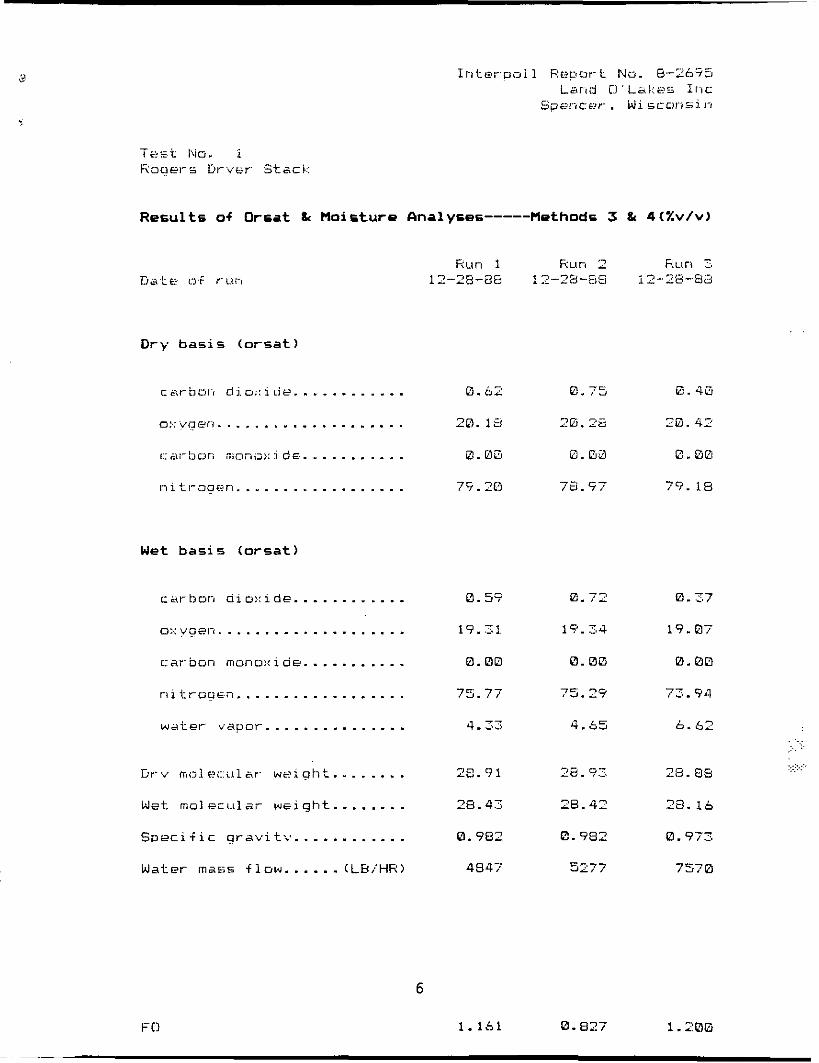
Results of Orsat & Moisture halyses-----Methodc 3 & 4(Y.v/v)
D r y bas ic (orsat)
.. -. i, -t illn Lii.u::ids.. . - . ._. . .. . o:.: vger;. . . . . I: .. .i I. , .dl dciri ntono:.: i dr;. . . . . . . . . . . n i t i - o a c m . . . . . . . I . . . . . . . . . .
. . . . . . . . . . . . . - .
W e t b a s i s (orsat)
carbon aiu:.: ide.. . . .. . _ .. . . o:.: yaet-,. . . . . . . - - . . . . . . . . . . . carbon rnuno:.:ide.. . . . . . ._ - - r i i t r o u t n .................. w a t e r v a p o r . . . . . ..........
L-rv rrsolf?~::i~1sr- w e i a i i t . . . . . . . . W e t . m o l eri.tlar w ~ i g h t . - . . . - . . Spsciiic aravi t ; . . . . . . . . . . . . . Water mass f l u w . . . . . . (LH/HR)
0.59
19.7.1
0. 0o
75.77
4-53
28.91
26.43
0.982
4647
0.72 0.27
1?.?,4 19.07
Q . 00 0.0D
75.29 /:..74
4.55 b. 62
--
28. 0.7 28. Q5
26.42 23. l a
0. 982 0.973
5277 7570
. ... . . ,. . . ...
6
F C1 1.161 0.027 1.20G
i n t e rc io ! l R e p o r t N i l . 8-2t95 Land U ' i a k e s lnc.
Spencer , W i s c o n s i n
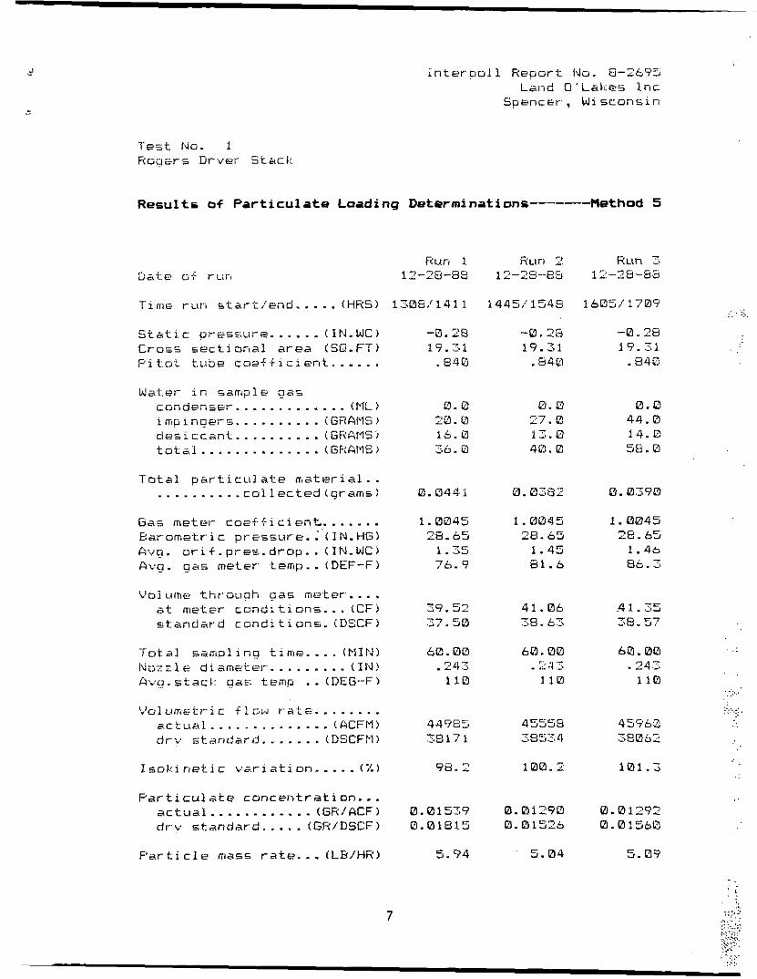
Results of Particulate Loading Determinations-------Method 5
Run 1 C.z, te uf riii? 12-78-89
T i n i f run s t a r t / e n d . . - . . (HRS) 1506/1411
S t a t i c p r e s s u r e . . .... ( I P 4 . W ) Ci-o=_s s e c t i o n a l a rea ( S G - F T ) Pi t . o . ? t , u b e cc12f.i i ;i ent ...... Water i n s a m p l e gas
C O G d e n SET. ............ (ML ) i m e 1 nue:-&. . ........ (GZAI'lS) des i c c a n t .......... ( SRAMS 1 t o t a l . . ............ ( G ~ t f i i l S j
Total p a r t i c ~ i l a t e m a t e r i a l . . ......... . c o l l e c t e d (cjrarn5)
G a s m e t e r c o e i f i c i e n t . . ..... Barornz-t:ric p r e s s u r e . : ' ( I N . H G ) A v q . o r i f . p r e s . d r o p . . (IN-WC) Avo. qas m e t e r . temp.. (DEF-F)
L'ol u i n e t h r a i g h Gas me.ter. . . . a t m e t e r c o n d : . t i o n s . . . (CF) s t a a d a r - d c o n d i t i o n s . (DSCF)
- ro ta ] s a ~ i i ~ g t imf. ... ( N I P , ) ,\j l E d i . . nme7 . el.'. ,, ... - . ....... ( IN A v q . s t a c k g a s t e m p .. (DEG-F)
L J o l L l , m e t l - - i c f l s a r . 1 - aLe . . . . . . . . a c t u a l . . ............ (ACFM) drv -1:arrdar;J.. ..... (DSCFM)
I s o k i r r e t i c v ; r i a t i o n . - . . - (7:)
P a r t i c u l a t e c a n c e r i t r a t i o n . . . a c t u a l . ........... ( G R / A C F ) di--v standard.. . . . (GR/DSCF)
P a r t i c l e mass r a t e . . . ( L B / H R )
-0.28 1?.'71 . e?&
0. e 20. E 16.0 2.0. E - ,
0.0441
1. 0345 28.65
1.25 76.9
- A9.52 77 .50
be. Q 0 .- 742 1 i 0
.> I
44985
35171.
98.2
0.0157.9 0.01815
5.94
7
Run 2 12-2y--&=j
1 44 5 / i 54 8
-a. 1s 19.31 .ti40
0. 0 27.0 1.7.. 0 4 e ~ . 0
0. 0282
1. L1045 L 78. 65
1.45 81.5
41.0b .:.a. 53
bo. 00 . .i .1 'I. 11'3
-
-.. '
45553 335::,4
100.2
0.Q1290 0.QI526
5. 0 4
Q . 0 44.0 14. E 5 S . D
4 1 . .x5 3Fj.5?
60.00 .24.2
110
Q.012'?2 0.01560
5.019
.. : . -. . . . .
... . . L . . .... .. . . . .
. .
..
. .

APPENDIX A
RESULTS OF PRELIMINARY VOLUMETRIC FLOW RATE DETERMINATIONS
.. . . ..
. . .. .. ..... . . . . ~.
. . . ... .. ::. . . ..: ~,. . . ..

I n t . e r p u l 1 R e p o r t N o . 8-2695 Land U'Lal res I n c
S p e n c e r , W i s c o n s i n
Results of Volumotric F l o w Rata Determination-------Method 2
CaCe o f 1jster.nii.riatiori.. .......... T i n , = ti+ D e t e r - m i n a t i o n . . ..... iHRSj Harometr ic 91-essure.. ..... (IN.HGj F'i itit t lite coef f i c i enC ...........
IUuriibsr ot s a m p l i n a p o r t s . . ....... T n t . a l number- of p o i n t s . . .........
L L ahatlie D + d L I - - ' - .................... c
St _L -.-I.. .. d i a m e t e r . . ............. < 1t.J)
fiuat area. . ............... ( S O . F T )
D' - . r e c t i . o n ai- f l o w ................
S t a t i c p r e s s u r e . . ......... ( 1 N . W C j
A v o . qas t e m u ............. iISF3-F)
M o i . s t u r e c o n t e n t . . ........ ( X L ' / V j
Aj,q . ve 1 oc i t y ..... ( F T ,'SEE )
G a s d e n s i t , - , . ............. ( L B / A C F j
M o l E c L l l a r w e i q h t . ..... (LEL'LBMOLE)
Mass f l o w of oas .......... (LH/HR)
1 i n e a r
L'o1umet:ric f l o w r a t e ............. a c t ~ i a 1 ................... i RCFM j d r v s t a n d a r d . . .......... (DSCFM)
- 1 24
Round
59.5
19.31
UP
-. 28
110
4. :;z
45141 25'39
A-1

. .
APPENDIX B
LOCATION OF TEST PORTS
.. .. .. . .
.. . ... . . .
...
. ..
. .

. .
-\ - .
-1- CIO
_ _
! '--- --
i
Fa& 1 __.___--
I \ 1
. ... .. . . . ..., .,.

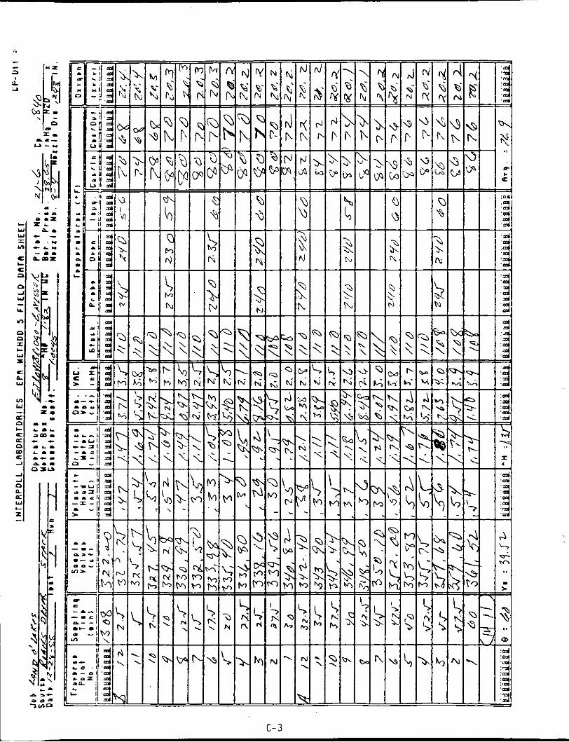
APPENDIX C
METHODS 2 - 6 FIELD DATA SHEETS
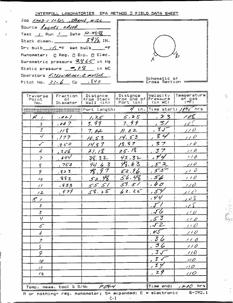
D r b b u l b / t 5 "F Wet bulb-
M a n o m e t e r : 0 R e g . @ E::p. 0 E l e c .
E a r o m e t r i c p r e s s u r e % y d c i n Hg
S t a t i c p r e s s u r e 0, ~ 5 3 i n WC I
'F I I 1 f i

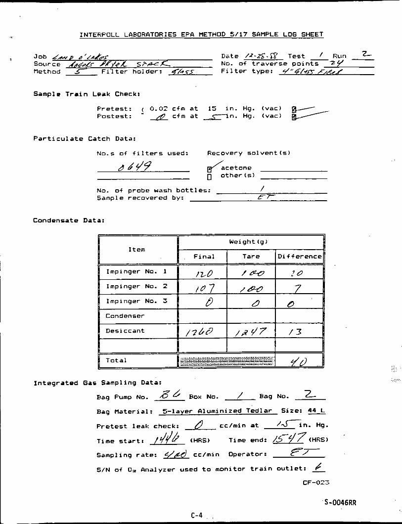
ii INTEHPOLL LAPORATORIES EP4 METHOD 5/17 SAMPLE LOG SHEET
Condenser
Desiccant / 3 3 L
Job 4 ‘/ALP 5 Date /.?-2q-E T e s t - Hun 1 SoLircE d,xr 5 /-AC,c NO. of t r a v e r s e p o l n t s z 7 Method F i l t e r ho lder : F i l t e r type: s / c 4 1 ~ ~ s J..&x
/ J / d / L
Sample T r a i n Leak Check:
P re tes t : ( 0.02 cfm a t 1-n. Hg. (vac) r. Postest : - & cfm a t J in. Hg. (vac) n/
P a r t i c u l a t e Catch Data:
No.s o f f i l t e r s used: Recovery s o l v e n t ( s )
No. of probe wash b o t t l e s : / Sample recovered by:
Condensate Data:
Weight(g)
D i f f e r e n c e
Impinger No. 1
fW 5- Impinger No. 2
__, .,L i_- =--=- _:.-.:~..- .::. -.II_ ..: . . . . . . . . . . . . . -. . . - . -. .. ._ -. . . . .. . . . ... . . . . --.- __.-I__. . .. . . . . . .- . . . . .. --I-. . . . . . . .. .-I TlG Tota l 1 I n t e g r a t e d Gas Sampling Data:
Hag Pump No. J d Box No. / nag NO. /
Bag Mate r ia l : 5 - layer A lumin ized Tedlar Size:
P r e t e s t leal: check: 6) cc/min a t /r in. Hg.
T i m e s t a r t : / y / y (HHS) Time end: /gd (HRS)
Sampling r a t e : f&d cc /min opera tor : E7-
S/N of O= Analyzer used t o moni tor t r a i n O u t l e t : _k CF-023
.. ,...
...
. . . . . ... ...... . . .. .... . .
S-0046RR c- 2
c- 3
INTERPOLL LABORATORIES EPA METHOD 5/17 SAMPLE LOG SHEET
Date /z-tS-'&' Test 2 R u n - t Job d r p d'c~&r Source 444 PLY //Ye A_ s r % u x _ NO. of t r a v e r s e p o i n t s z4c method F i ' l t e r ho lder : F i l t e r type: L / ' ' ~ [ + C ~,,q//
F i n a l Tare
Sample T r a i n Leak Check:
D i f f e rence
P r e t e s t : ( 0.02 cfm at 15 i n . Hg. (vac) Pos tes t : - A c f m a t a n . Hg. (vac) /
P a r t i c u l a t e Catch Data:
ND.S of f i l t e r s used: Recovery so l ven t ( 5 )
No. of probe uash b o t t l e s : / Sample recovered by: E 7
Condensate Data:
/LO IO Impinger No. 1
Impinger No. 2
Condenser
I n t e g r a t e d Gas Sampling Data:
Hag Pump No. How No. / Hag No. 2- Bag Mate r ia l : %layer a lumin ized Tedlar Size:
P r e t e s t l e a k check: cc/min a t /tin. Hg.
T i m e s t a r t : 1/44 (HRS) Time end: /5-g7 (HRS)
Sampling ra te : L/A cc/min Operator: f?- S/N o f O= Analyzer used t o moni tor t r a i n o u t l e t :
CF-023
S-0046RR c-4 . .
.. . ... . . . .
... ... . .....

c -5
-__ INTEHF'OLL LAHDRATORIES EPA METHOD 5/17 SAMPLE LOG SHEET
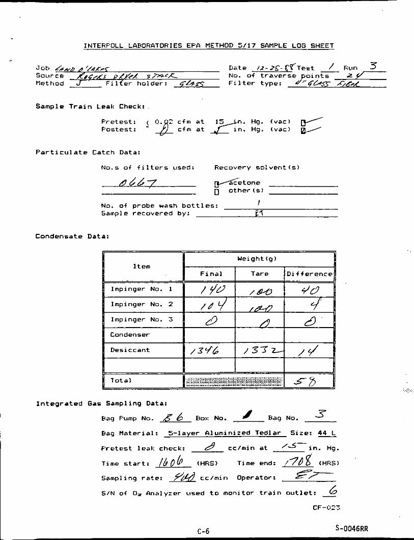
Jab &,,,a '/4,C*s- Date / 1 - 2 S ' - c f T e s t R u n 3 S G L l r C E RiCrA5 PLYFA s / - + c x No. of t r a v e r s e po in ts 2 7 method J F i l f e r ho lder : GrRS F i l t e r type: d ' ' 4 & ~ C,K~A
Sample T r a i n Leak Check:
P re tes t : fOJf c f m a t ng. (vat) e Postest : cfm a t Hg. (vac)
P a r t i c u l a t e Catch Data:
No.s of f i l t e r s used: Recovery so lvent (5 )
~ d 6 7 f i e t o n e 0 o the rcs )
No. of probe wash b o t t l e s : Sample recovered by: i3
I
Condensate Data:
I Weight(g)
F i n a l I Tare D i f f e r e n c e
Condenser
Desiccant % / 3 9 4 I / 3 7 4 ,J 1
I n t e g r a t e d Gas Sampling Data:
Hag No. 3 Bag Pump NO. 6 BO,: NO. I
Hag Ma te r ia l : 5 - l aye r N u m i n i z e d Tedlar S i z e : 4%
P r e t e s t leal: check: A' cc/min a t '3-in. ng.
Time s t a r t : /hob (HRS) Time end: / 7 b f (HRS)
Sampling r a t e : yifd cc /min Operator: ST--- S/N of D= Analyzer used t o moni tor t r a i n o u t l e t : - 6
CF-023
.. . ..... .....
C-6 S-0046RR

. . .... ....
c- 7

APPENDIX D
LABORATORY DATA SHEETS
- .., .. .. . . . .. . . .. ..., ....
.: ... . . .: :... :.>: ......

I n t e r p o l 1 L a b o r a t o r i e s (611) 796-602D
C h a i n o f C u s t o d y S a m p l e D e p o s i t i on S h e e t
J o b lAvb 4 L #.Y€s- n S o u r c e d&5/ Tsam L e a d e r T e s t S i t e ' e D a t e S u b m i t t e d ' / z - Z % - g % D a t e of T e s t / Z -2-T-gq T e s t N o . I No. o f R u n s C o m p l e t e d 3
No. of S a m p l e s
9 Type o f S a m p l e
P r o b e Wash : @one gD.1. Water
Impin C a t c h : Water
0"" H,OZ n4M5 Hg On1 y 04M5 M e t a l s 01.0 N NaOH n o t h e r
[ IOther
d r EPA M-5 ofis p e r EPA M-17 nother
oMN P r o t o c o l p Y P r o t o c o 1 gEF'fi M-5 or 8 Oficid Gases OFormal d e h y d e OMetal s O O t h e r
0"s p e r EPfi M - 1 3 nother
ofi5 p e r EF'fi M-7A nother
s a m p l e
I
D a t e T i m e (HRS)
O x i d e s of N i t r o g e n (NO. 1
0 F u e l S a m p l e 0 A g g r e g a t e
P a r t i c l e Size
Aud i t Samp 1 e5 OSul fur Di ox i d e O O x i d e s o f N i t . [ IO the r
Source In format ion
A n a l y s i s R e q u i r e d Comments
p t t a c h e d f u e l Form #S-015;RRH
OX-Hay S e d i g r a p h OHahco Method n o t h e r
n A 5 per EPA M-5 AS p e r EPA PI-7A OOther
1 ) T y p e of S o u r c e : 0 B o i l e r 0 A s p h a l t P l a n t 0 I n c i n e r a t o r
2) F u e l : 0 C o a l 0 Wood v a s 0 O i l 0 RDF 0 O t h e r Z ) I s s a m p l e c o m b u s t i b l e ? 0 N o 0 Y e s 4 ) D o e s s a m p l e n e e d s p e c i a l h a n d l i n g ? 0 No 0 Y e s I f y e s , e x p l a i n
S-278HRRR
0 O t h e r
D- 1

I n t e r p o l 1 L a b o r a t o r i e s (612) 786-60=0
€PA N e t h o d 3 Data Report ing S h e e t O r s a t a n a l y s i s
I I I I I I I I I I R
I I I I I 3 I I-I'i - I I
. .. 1
. ... . . ... I I-- 2 ..
I I I 3 I I I I I
m m b i e n t a ir QA Check WOrsat hna lyzer System Leak Check Fuel Type FD Rango
EPA Method 3 G u i d e l i n e s
F, W i t h i n EPA M-3 G u i d e l i n e s Coal : f o r f u e l t y p o . h t h r a c i t e / L i g n i t e 1.016-1.130
61 tuminous 1.00;- 1.2;0 Whore F - 20 9-0 o i i :
D1 sti 1 l a t e 1.260-1.41 Z Res1 dual 1.21D-1- Z70
N a t ur a 1 1.600-1.8;5 Propane 1.4Z4-1.596
==---&e Gas: .
F=Flask (250 cc a11 g l a s s ) Butane 1.405-1.55; Wood/Wood Bark 1.000-1.1:0
LSC-04-BR B=Tedl at- Hag (5-1 d y e r )
D- 2

I n te rpo l 1 Laborator ies (612) 786-bQ70
€PA tlethod 5 D a t a R e p o r t i n g S h e e t I m p i ng er C a t c h / W i ccon o i n P r o t oco 1
I So l vent Pha80 CIqueous Phase
0 T e s t R u n D i s h 140. 77 D i s h NO. 6 .z F i e l d B lank D i s h T a r e W t . aqd c o y l J g D i s h Tare W t . w-367-3c;’ g Log N u m b e r 72 0 7 - 03 D i s h + S a m p l e Wt.*p&c5+g D i s h + S a m p l e W t . 9 / 1 3 7 - J ? g C o m m e n t s S a m p l e W t . c ocw;g S a m p l e W t . 4 L’CC I g
1 T e s t H u n - D i s h No. 4-7 D l s h NO. 6 5- Log N u m b e r D i s h T a r e W t . y C 6 7 D i s h T a r e W t . 7’6, 977’fig C o m m e n t s - 0 6 D i s h + S a m p l e W t . y L S r g a D i s h + S a m p l e W t .yr . 9 7 7 Q 9
S a m p l e W t . O . u c y 3 g S a m p l e W t . G . C ) o L z g . 2
T e s t R u n A D i s h No. 52- D i s h No. 66 Log N u m b e r ‘ - @ D i s h T a r e W t . y > 77739 D i s h T a r e W t . rU,3@8-& C o m m e n t s D i s h + S a m p l e Wt.yz 7 7 e 3 g D i s h + S a m p l e W t . f d . 3/-109
3 T s s t R u n L D i s h No. stz D i s h No. 6 7 <
Log N u m b e r - 4 D i s h T a r e W t . S ? . 2 2 3 7 g D i s h T a r e W t . 77Pt?79g C o m m e n t s D i s h + S a m p l e Wt.SO.1266 g D i s h + S a m p l e Wt . y7 f?#g
4
S a m p l e W t . 4.0029 g S a m p l e W t . e. 0 0 3 0 g
Log N u m b e r D i s h T a r e W t . g D i s h T a r e W t . 9 C o m m e n t s D i s h + S a m p l e Ut. g D i s h + S a m p l e W t . 9
S a m p l e W t . g S a m p l e W t . 9
D i s h No. T e s t - R u n - D l 5 h NO.
5
~ ~~~~ ~~
T s s t __ R u n - D i s h No. D i s h No. Log FJumber D i s h T a r e W t . g D i s h T a r e U t . 9 C o m m e n t s D i s h + S a m p l e W t . g D i s h + S a m p l e W t . 9
S a m p l e W t . g S a m p l e W t . 9

I n te rpo l1 Labora to r ies (612) 786-5320
EPA Nethod 5 D a t a R e p o r t i n g Sheet Probe/CyCl one Wash
3
8
1
2
T e s t / R u n A D i s h No.-, V o l . of S o l v e n t z m l D i s h T a r e W t . 4 2 ?JJ 25- 9 Log N u m b e r - / z D i s h + S a m p l e W t . Y Z 972-T 9 C o m m e n t s S r m p l r Ut. n. u t w ~ 9
Jcb i,,,,i 61!&4 -25 Source O.,Cr n, ‘U c; r T e a m Leader E r T e s t s i t e J ~ J 7 ’
- D a t e S u b m i t t e d D a t e of T e s t 12 Lt : . SfZ T e s t No. D a t e of A n a l y s i s / t - Z 7 - d U T e c h n i c i a n /n,s /<w T r a n s p o r t Leakage won‘ 0 m l Solvent A c e&- 1.
No. of H u n s C o m p l e t e d i. &,
4
5
2 9
- T e s t i R u n L D i s h NO. F i e l d blanb. D i s h T a r e W t . 46. / t v d Log Number 7.2 0 7 -0) D l s h + S d m p l e W t . ‘&, 76 79 9 V o l . of S o l v e n t a m l S a m p l e W t . 0. 0 0 33 9
V o l . of S o l v e n t / Y O m l D i s h T a r e W t . v2 -. 2 a 5~ 9 Log N u m b e r -oc/ D i s h + S a m p l e W t . % - 17.J6Y 9 C o m m e n t s S a m p l e W t . 0 . 0 2 u6 9
Vol. of S o l v e n t a m l D i s h T a r e W t . 9 F L 65- 9 Log N u m b e r -05 DI s h + S a m p l e w t - %?. 7 / 7 F 9 C o m m e n t s S a m p l w W t . 0, 0 1 5-/ 9
*Sol bent R e s i d u e a u g / m l
T w s t R u n L DISh NO.-.
D i s h No.- T e s t - R u n X
Test- Run- D i s h 140. C o l . of Solvent- m l D i s h T a r e W t . 9 Log N u m b e r D i s h + S a m p l e W t . 9 C o m m e n t s S a m p l e W t . 9
L’ol. of Solvent- m l D i s h T a r e W t . 9 Log N u m b e r D i s h + S a m p l e U t . 9 C o m m e n t s S a m p l e W t . 9
- Test-Run- D i s h NO-
- Resu 1 t r :
Run 3 R u n 4 Run S F i e l d E l k . R u n 1 Run 2 ^ .
. ’. ..,..: ,..::,. ..:.. ., . . . . ,, , ~ ,;, .. .....,
, . .. .
. . . . . . . ..
In te rpo l 1 L a b o r a t o r i e s (612) 7a6-t.0~1
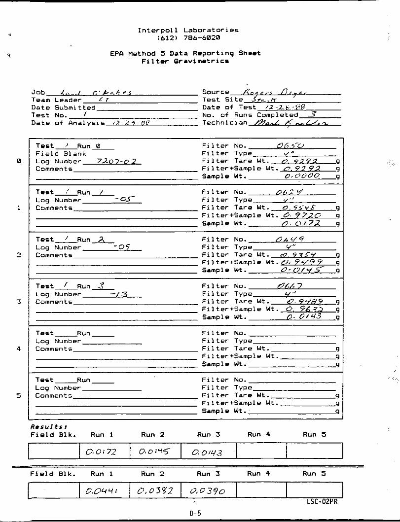
EPA Method S Data R e p o r t i n g Sheet F i 1 t a r O r a v i met r I c=
C,0172
Job L. ... I r ; ' b < . h 6 5 Source o n f, I I . .< ,
Team Leader L r Test S i t e Js'+,.h. D a t e Submi t ted Date of T e s t /2-26 .?P T e s t No. I No. o f R u n 5 Completed 3 Date of A n a l y s i s 12 ;?r-eP Techn ic ian &d /(-&f,%
00 0 i 4 5 0 6 0 14.3 1
T e s t L R u n L F i 1 t e r No. (963-0 F i 1 t e r Type "
Sample W t . o,c~ooo g
F i e l d Etlanl: Log Number 7207-0 2 F i l t e r Tare W t . 0. 9292 g Comments F i 1 ter+Sample W t . c, 9 2 92 g
T e s t .'Run- F i l t e r No. OL;1 u/
Comments F i l t e r Tare W t . D 5 r v 6 9
Sample W t . n. 0/7R 9
- 03- F i 1 t e r Type ,, Log Number
F i l t e r + S a m p l e W t . G. 972C. g
F i 1 t e r No. d b cf 9 I ,
T e s t R u n A Log Number - 07 F i 1 t e r Type Comments F i l t e r Ta re W t . &. 47 c y 9
9 9 9 Sample W t . 0- V / Y 5 9
- F i l t e r + S a m p l e W t . 0 , 9-/
0.04 4 1 0'0 3172
~ ~~
T e s t R u n 3 F i 1 t e r No. &A/, 7
Comments F i l t e r Tare W t . 0 Y . / H 9 g
Sample W t . 0. 0/43 g
,# Log Number - . F i 1 t e r Type
F i l t e r + S a m p l e W t . c>. F6?7 9
9.0390
T e s t __ F i 1 ter No. R u n - Log Number F i l t e r Type Comment 5 F i 1 t e r Ta re W t . 9
F i l t e r + S a m p l e W t . 9 Sample W t . 9
T e s t - Run - F i 1 t e r No. Log Number Fi 1 t e r Type Comments F i 1 t e r Tare W t . 9
F i 1 ter+Sampl e W t . 9 Sample W t . 9
I' .
~. . . . . . ..

f
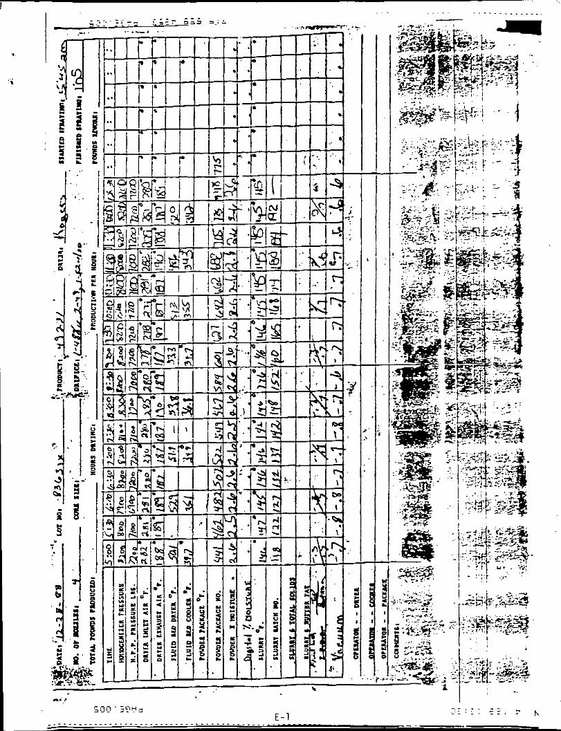
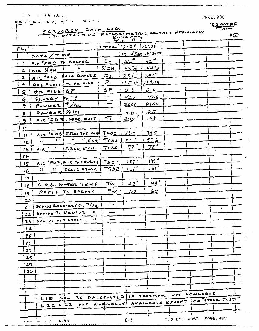
APPENDIX E
PROCESS DATA
... ....
.._.. . .
.............. . .
- h . - - _ - ._ . . . . . . . . . .


PQGE . B O 2 P . E 3
. .
APPENDIX F
PROCEDURES

PARTICULATE LOADINGS AND EUISSION RATES
The pa r t i cu la te emission ra tes a t t h i s s i t e were determined per EPA Method 5, CFR T i t l e 40, Par t 60, Appendix A (Revised J u l y 1 , 1987). In t h i s procedure, a p re l im inary v e l o c i t y p r o f i l e of the gases i n the f l u e i s obtained by means o f a temperature and ve loc i t y t raverse. On the basis of these values, sampling nozzles of appropriate diameter are selected t o allow i sok ine t i c sampling, a necessary p rerequ is i re f o r ob- t a i n i n g a representative sampie.
Tne sampling t r a i n consis ts o f a heated sampling probe eauipped w i t h a type S p i t o t and a thermocouple. The probe i s attached t o a sam- p l i n g mooule which houses the a l l - g lass i n l i n e f i l t e r holder i n a tem- perature cormt ro l led oven. I n add i t ion , t he sampling module a lso houses the impinger case and a s i l i c a gel d ry ing column. The sanpling module i s connected y means o f an umb i l i ca l cord t o the contro l module which houses t h e d ry t e s t gasmeter, t he ca l i b ra ted o r i f i c e , a leak less pump, two i n c l i n e d manometers, and a l l con t ro l s required f o r operat ing t h e sampl i ng t r a i n .
Pa r t i cu la te samples were co l l ec ted as fo l lows: The sample gas was drawn i n through the sampling probe l s o k i n e t i c a l l y and passed through a 4-inch diameter Gelman Type A/E g lass f i b e r f i l t e r . The p a r t i c u l a t e s were removed a t t h i s po in t and co l lec ted on the f i l t e r . The gases then passed though an ice-cooled impinger t r a i n and a desiccant-packed d ry ing column which q u a n t i t a t i v e l y absorb a l l mo is tu re from t h e sample gas stream a f t e r which t,he sample gas passes through the pump and the d ry t e s t gasmeter which in tegrates the sample gas f low throughout the course o f the t e s t . A Cal ibrated o r i f i c e attached t o the o u t l e t o f t he gas- meter provides instantaneous f l ow r a t e data.
A representative p a r t i c u l a t e sample was acquired by sampling f o r equal per iods o f t ime a t the cen t ro id o f a number o f equal regions i n the duct or stack. The sampling r a t e i s adjusted a t each s i t e such t h a t an i s o k i n e t i c sampling cond i t ion p reva i l s . NomograDhs are used t o a i d i n the rap id determination o f t he sampling ra te .
. . . . .
:.:.::>
3a P l ! 1-5 I
../
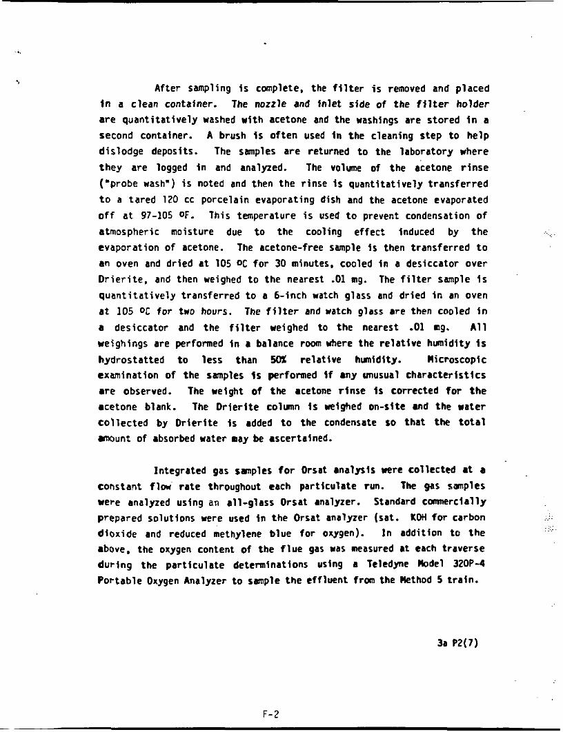
, After sampling is complete, the filter is removed and placed
in a clean Container. The nozzle and inlet side of the filter holder are quantitatively washed with acetone and the washings are stored in a second container. A brush Is often used in the cleaning step to help dislodge deposits. The samples are returned to the laboratory where they are logged in and analyzed. The v o l w of the acetone rinse ('probe wash") is noted and then the rinse is quantitatively transferred to a tared 120 cc porcelain evaporating dish and the acetone evaporated off at 97-105 OF. This temperature is used to prevent condensation of atmospheric moisture due to the cooling effect induced by the evaporation of acetone. The acetone-free sample i s then transferred to an oven and dried at 105 OC for 30 minutes, cooled in a desiccator over Drierite. and then weighed to the nearest -01 mg. The filter sample Is quantitatively transferred to a 6-inch watch glass and dried in an oven at 105 ot for two hours. The filter and watch glass are then cooled in a desiccator and the filter weighed to the nearest -01 ng. All ueighings are performed in a balance room h e r e the relative humidity is hydrostatted to less than 50% relative hmidity. Microscopic examination of the samples Is performed if any unusual characteristics are observed. The weight of the acetone rinse Is corrected for the acetone blank. The Drierite column is weighed on-site and the water collected by Orierite Is added to the condensate SO that the total a u n t of absorbed water may be ascertained.
Integrated gas sanples for Orsat analysis were collected at a constar)t flw rate throughout each particulate run. The gas SmPleS were analyzed using an all-glass Orsat analyzer. Standard cannerclally prCpared solutions were used in the Orsat analyzer (sat. Kotl for carbon dioxide and reduced methylene blue for oxygen). In addition to the above. the oxygen content of the flue gas was measured at each traverse during the particulate determinations using a Teledyne Model 320P-4 Portable Oxygen Analyzer to sanple the effluent from the Uethod 5 train.
3a P2(7)
...
...
. ...
F- 2 -

Version 1.3 1/88
Interpol1 Laboratories (612)786-6020
Condensible Organic Cocapounds Analysis (S ta t e of Wisconsin - EPA Method 5 )
Method TI-8672-YI
Equipment: Separatory funnel - 500 cc with Teflon stopcock
Powder funnel - 75 mn IO with a g lass wood plug
Evaporating dish(es) - 200 cc or 250 cc beaker
Reagents : Methylene chlor ide
Sodium s u l f a t e - (ACS) g r a n u l a r anhydrous (pu r i f i ed by heating for four hours i n a sha l low t ray)
SAMPLING: An a l l -g l a s s impinger assembly is used In t h e back ha l f o f
t h e €PA Method 5 sampling t r a i n when an organic wet catch i s t o be co l l ec t ed . The impinger assembly cons is t s o f a modified impinger, a Greenburg Smith impinger followed by another modified impinger. The t h i r d impinger s h o u l d have a temperature measuring device a t t h e . o u t l e t upstream of a f ina l impinger or desiccant column t o monitor the temperature of the o u t l e t gas stream. Prior t o the s t a r t of the test. each of the f i r s t two impingers should be charged with 100 g o f Class I water. The Method 5 t r a i n should be operated as provided for i n EPA Method 5. Ice should be added t o the impinger b a t h t o keep t h e temperature o f the gas a t the o u t l e t a t o r l e s s t h a n 68 OF. After t h e
post tes t leak check, the impinger t r a in i s removed and impinger contents poured in to a tared a l l -g l a s s sample bot t le and closed w i t h a Teflon-lined cap. The sample b o t t l e i s then weighed and the t o t a l condensate calculated by subtract ion o f the bo t t l e t a r e weight and t h e
..... ..
' F-3

Version 1.2 11/87
weight of i n i t i a l water added t o the impingers (200 9). A l abe l i s aff ixed and t h e sample is returned t o the laboratory for ana lys i s . The sample s h o u l d be stored a t 4 OC i f the analysis is not conducted within 48 hours .
ANAlYSIS :
1.
2.
3.
4.
5.
6.
Sample b o t t l e s . a r e removed from s torage and the conten ts quant i ta t ive ly t ransferred t o a clean 500 cc separatory f u n n e l equipped with a Teflon stopcock.
Rinse the sample container with d i s t i l l e d water and add t o separatory funnel.
Then r inse the sample container with acetone and pour t h r o u g h sodium su l f a t e i n t o a t a r e beaker marked A.
The sample i s t h e n extracted consecutively w i t h three 50 cc a l iquo t s of methylene chloride. The extract ion is performed according t o normal laboratory prac t ice observing t h e customary sa fe ty precaution of re leas ing excess pressure a f t e r each shaking.
After each of the three extract ions a r e completed, the organic solvent should be dried by passing i t through a f u n n e l containing anhydrous sodium su l f a t e and col lect ing i t and two 50 cc rinses i n t he tared beaker marked A ( the same one used to catch the acetone container r inse) .
Evaporate t o dryness i n a hood a t 70 O F or less. Do not evaporate so quickly as t o allow evaporative cooling t o lower the temperature of the container below the dew p o i n t otherwise water will be condensed i n the container.
. ,. ...
F-4

Version 1.2 11/87
7.
8.
9.
Desiccate for two hours i n a sealed desiccator and f i n a l weigh. Report a l l results i n grams. All weighings should be made t o nearest 0.1 mg (four places).
The remaining l i q u i d i n the separatory funnel is t h e n transferred t o a ta red beaker marked B and is evaporated t o dryness a t 220 O F 2 10 O F . The analyst may take an a l i q u o t o f t h e sample, t r a n s f e r r i n g i t t o a tared beaker and evaporate t o dryness a t 220 O F 2 10 OF. If an al iquot is used. t he weight of the sample a n d a l i q u o t wi l l have t o be taken t o cor rec t f o r the to ta l sample weight.
After the drying step, t h e sample is cooled i n a des icca tor and weighted t o a constant weight t o the nearest 0.1 mg.
Calculation ( i f a l i quo t is taken):
grams = b r a m s recovered from a l i q u o t ) x ( to t a l volume (ml) o r grams o f sample) (a l iquot volume (ml) o r grams used)
If volume i s used. i t must be used f o r both t h e a l iquot and sample. The same goes for u s i n g w e i g h t .
10. A field blank should be analyzed i n an identical manner. I f a field blank i s not submit ted, take an al iquot of Class I water equal i n volume t o the samples and analyze i n a s i m i l a r manner.
11. The results f o r container A are t o be marked i n the organic section of In te rpol l Form 1LSC-036.
1 2 . The resul ts f o r container B are t o be marked i n the inorganic section of In te rpol l Form ILSC-036.
. . .. . . .. .... .~ . ... .... . . .. ..
..:. ...... ... .. .
F-5 -

. .
0 W V 4
\
a
E
W I- w
v ) U u > 0 a
. . .,. . . .
..... .....
F- 6 .. . -

.. .. ....
.. . ....
APPENDIX 0
CALCULATION MUATIONS
. . . . .. . . . . . . . . . ... . . . . . . .
. ..-..

CALCULATION EQUATIONS
METHOD 2
= 60 Vs A Qa
RH* = 100 (vPtwb 0 .0003641 Ps ( T d b - T w b ) ) / V P t d b
. ..
. . . . . .... . ... . ..
. . .. ......_ . -.. .
*Al ternate equat ions f o r c a l c u l a t i n g moisture c o n t e n t from wet bulb and dry buld d a t a .
a
G-1

CALCULATION EQUATIONS
METHOD 3
10O(%O2 - ).5% CO) %EA = 0 .264% N2 - %02 + 0.5% CO
= O.44(%CO2) + 0.32 (%02) + 0.28 (%N2 + %CO) Md
= Md ( I - Bws) + 0.18 Bws MS
- - "w ( s t d ) Bws 'w(std) + " m ( s t d )
6-2

CALCULATION EQUATIONS
METHOD 5
pbar + iTV13.6
'm( avg) = 17.65 V,,, Y ( 1 'm(std)
= 0.0472 VIS 'w( std)
- - "w ( std )
'w(std) + 'm(std)
V = 0.0944 ( P Ts(avg) V A U ( I m(std) - Bws) 1
s s n
15.43 M
'm(std) - -
272.3 Mn PF - r - - s( avg) ('w( std) 'm( s t d ) ) i
= 8.5714 x C, Qs,d
1.3228 x lo-' Mp A - - O An
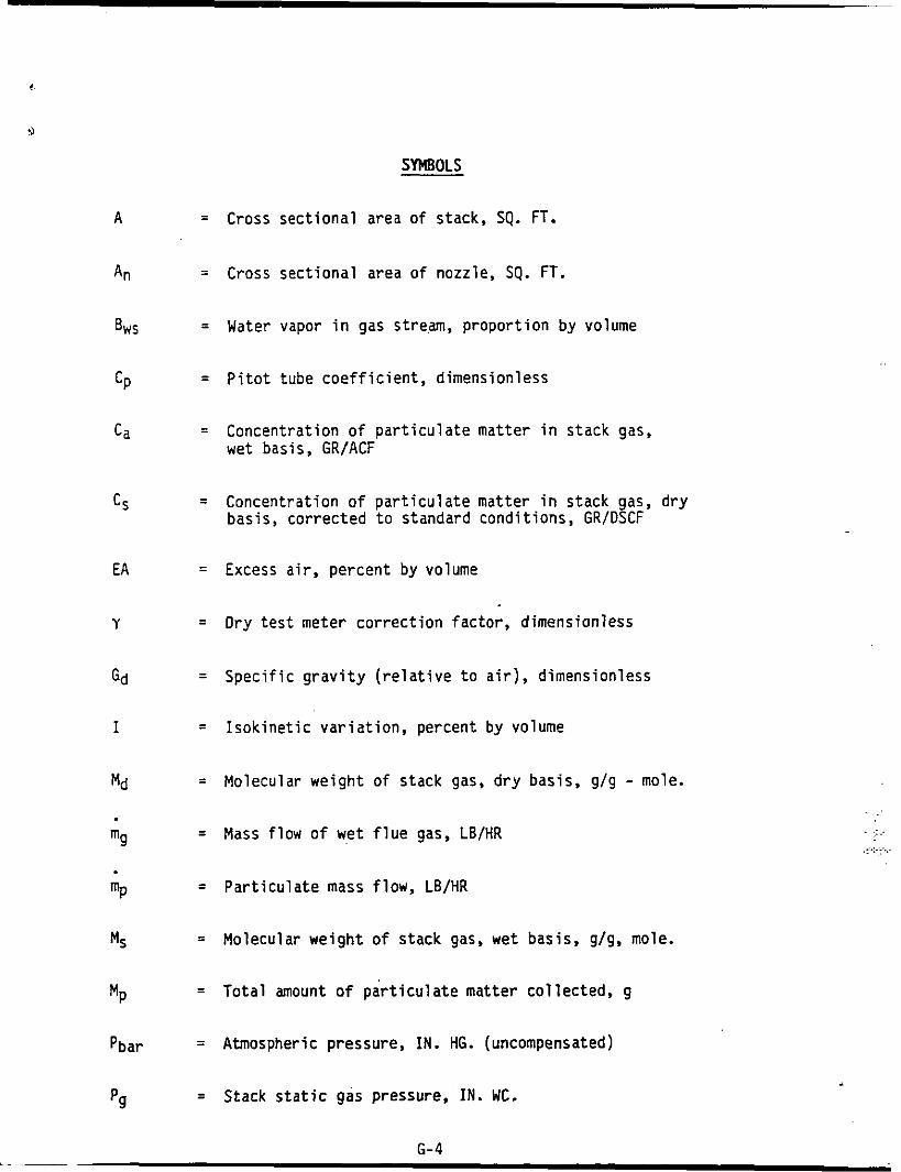
SYMBOLS
= Cross sectional area of stack, SQ. FT.
= Cross sectional area of nozzle, SQ. FT.
= Water vapor in gas stream, proportion by volume
= Pitot tube coefficient, dimensionless
= Concentration of particulate matter in stack gas, wet basis, GR/ACF
Concentration of particulate matter in stack gas, dry basis, corrected to standard conditions, GR/DSCF
=
= Excess air, percent by volume
= Dry test meter correction factor, dimensionless
= Specific gravity (relative to air), dimensionless
= Isokinetic variation, percent by volume
= Molecular weight of stack gas, dry basis, g/g - mole.
Mass flow of wet flue gas, LB/HR =
= Particulate mass flow, LB/HR
= Molecular weight of stack gas. wet basis, g/g, mole.
= Total amount o f particulate matter collected, g
= Atmospheric pressure, IN. HG. (uncompensated)
= Stack static gas pressure, IN. WC.
6-4
. ..: __.__ -... .. . ,
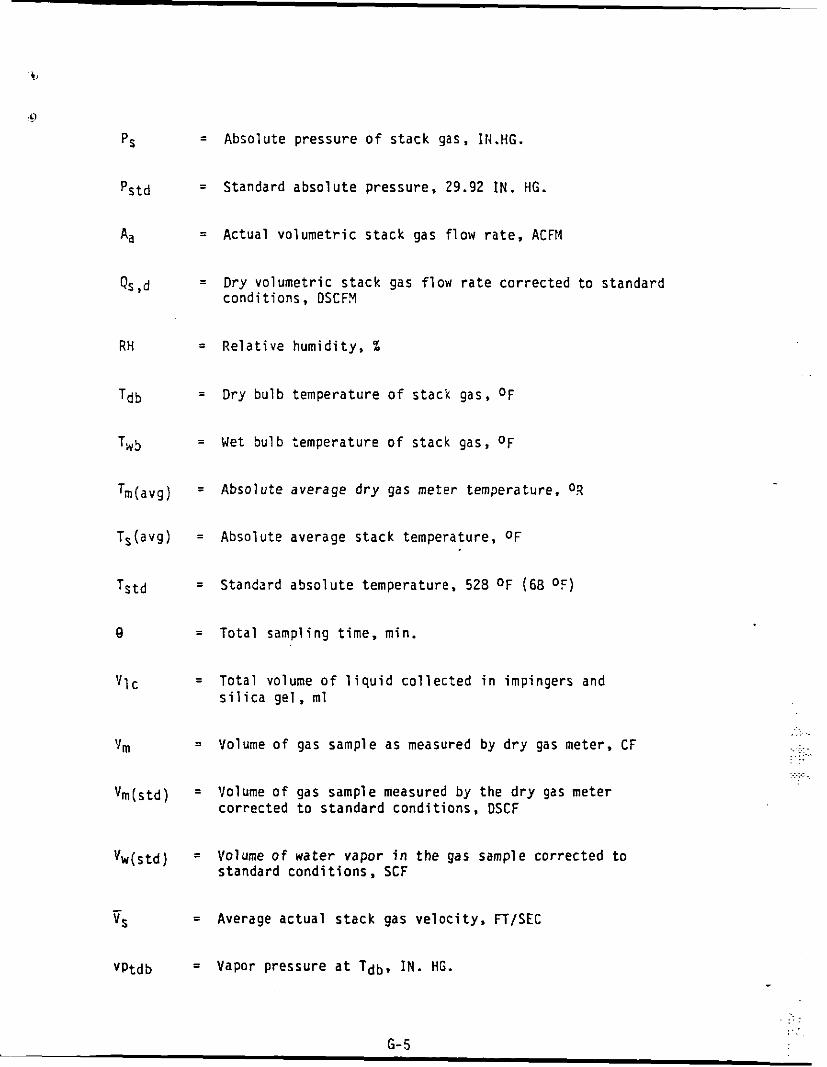
Absolute pressure o f stack g a s , II.I.HG.
Standard absolute pressure, 29.92 IN. HG.
Actual volumetric s tack gas flow r a t e , ACFM
Dry volumetric s tack gas flow rate corrected t o standard conditions, DSCFX
Relative humidity, %
Dry bulb temperature of stack gas, O F
Wet bulb temperature o f stack gas, O F
Absolute average dry gas meter temperature. 02
Absolute average stack temperature, O F
Standard absolute temperature. 528 O F (68 O F )
Total sampling time, m i n .
Total volume of l i q u i d collected i n impingers and s i l i c a gel , ml
Volume of gas sample a s measured by dry gas meter, C F
Volume of gas sample measured by the dry gas meter corrected t o standard conditions, DSCF
Volume o f water vapor i n the gas sample corrected t o standard condi t ions, SCF
Average actual s tack gas velocity. FT/SEC
. .. .
. .... .. . .. ...... . ..
.... ... .....
. = Vapor pressure a t Tdb . IN. HG.
.. . . . . . .. . , .
6-5 L

vPtwb = Vapor pressure a t Twb, IN. HG
rn = Average pressure d i f f e r e n t i a l across t h e o r i f i c e meter, I N . WC.
AP = Velocity pressure of stack g a s , IN. WC
Y = Dry t e s t meter correct ion coef f ic ien t , dimensionless
P = Actual gas densi ty . LS/ACF
6-6
... . .. . .. .
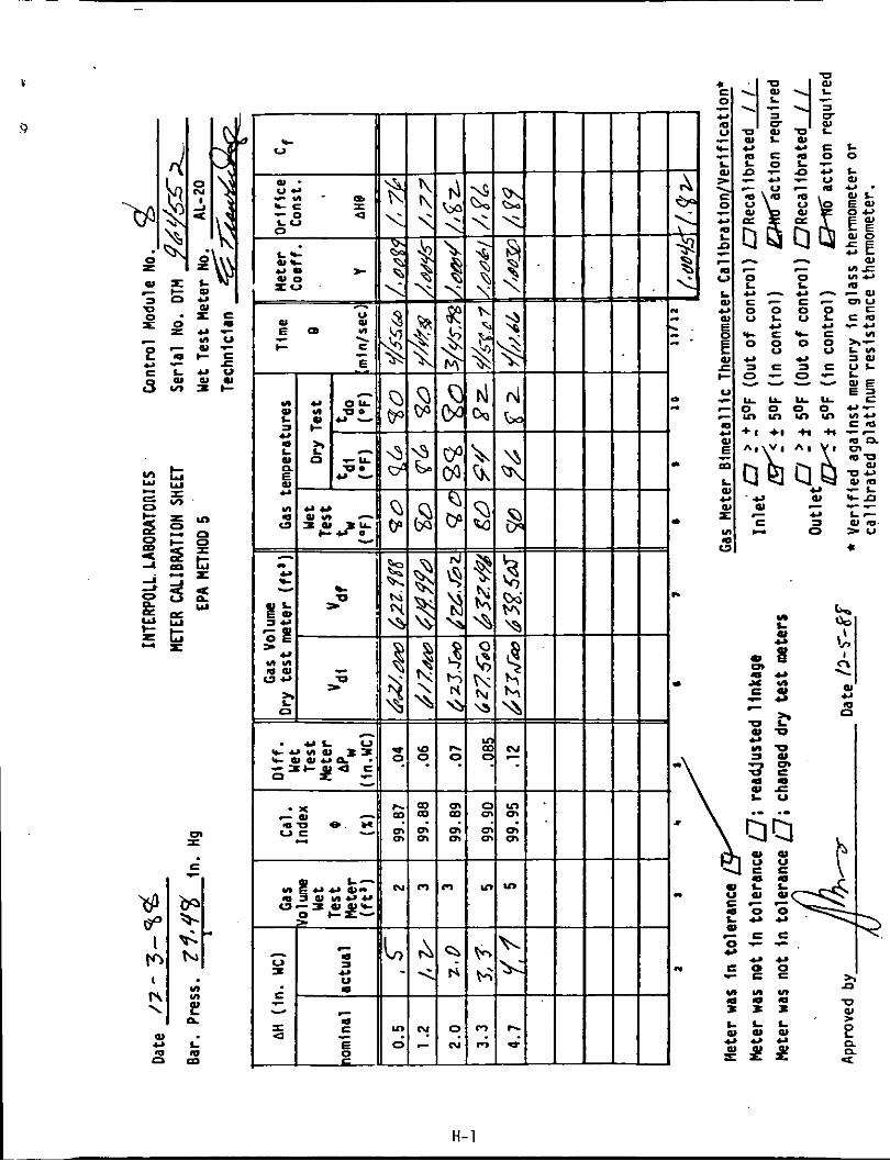
APPENDIX H
SAMPLING TRAIN CALIBRATION DATA
...
..... -....
I% c I
m I
w - Y L m m c a m
. . . . 1 .
D I
.
. I.
-
Y I Y I Y I m a 4 v 3 3 1 W L L L w w w * . a - n n
I > e B P Z U
?
H-1

In W .- L 0 0 U N L a 0 1
6 Q -IC
m o
n w
In a %
%
U v)
6 In 3 0 c 6 c 0 c, L
- m n 7- - 6 0
X 0
L W U
m
2
W W 0, c - W N
L W
E 0 0 W
n
n
.. c, L
W
u- 0
W c, 6 O
x a
h N LD 0 * a 0,
0 I
6 L W u)
L W U W x U LD W I-
> L
c -
n r c W 3 x 0 0 E Y
m
.. 0 L
X 0
L W U W S
m
u
ig? - u 0 6 > - a m u *- 0 e
n- o . -3u \u- E . a a - 0 0 - w
L W
w e I- V
-6 Q W
Y
urn
e a - L 0) c, a m *+
0 r t! 0
0 n a
m a -
n o n o w 0
C Q O L D Q W
. . .
W v ) u )
a a a N N N 1 1 1
W Q Q
- 0 3 0
m - - I n w
a r e 4
H-2

I n t e r p o l l Laboratories
(612) 786-6020
Nozzle Ca l ibra t ion
Data Sheet
Date of Calibrat ion: December 28, 1988
Technician: E. Trowbridge
Nozzle Number 8-4
Nozzle rotated by 60 degree increments and diameter measured t o nearest
0.001 inch. Observed readings and average:
Posit ion Diameter
(inches)
0.242
0.243
0.245
Average: 0.243
H-3

Interpol1 Laboratories (612)786-6020
S-Type P i t o t Tube Inspectlon Sheet
Pitobe No. 6-21
P i t o t tube dimensions:
0 -316 IN. 0.464 IN. 0.462 IN.
1. External tubing diameter (Dt) 2. 3.
Base t o Side A opening plane (PA) Base t o Side B opening plane (P,)
Alignment:
4. a1 <loo 0 Degrees 5. a2 <loo 0 Degrees
1 Degrees 6. B1 < So 1 Degrees 7. B2 < So
8 . z <.125' 0.02 IN. 9. u c.0625' 0.01 IN.
Distance from P i t o t t o Probe Components: 10. P i t o t t o 0.500 IN. nozzle 0.762
11. P i t o t t o probe sheath
12. P i t o t t o thermocouple ( p a r a l l e l to probe) 3.00
13. P i t o t t o thermocouple (perpendlcular to probe) 0.762
IN.
IN.
IN.
IN.
3.00
Inspected by: Date o f Inspectlon:
May 26. 1988 E. Trowbridqe
H-4

l i ,.. m m N I v)
L al o W E 0
L .r w u .. u s
u w w - E o c o o .- E n m L m w z U L
u + n
Y VI w - I -u
L -
E E 3.-
.r 0) c p : 3
- o m w O b
e m
- 1
d
0 h
L. 0 d
0
0 N -
0 0 d
0 0
0 0 N
0 0
0 C cc:
0 0 m
0
0 0 v)
1
H-5